a systems engineering capability maturity model, … model secmm-95-01 cmu/sei-95-mm-003 a systems...
TRANSCRIPT

Maturity ModelSECMM-95-01CMU/SEI-95-MM-003
A Systems EngineeringCapability Maturity ModelSM,Version 1.1
SE - CMM
Systems Engineering Improvement
Systems EngineeringCapability Maturity Model Project
November 1995


Maturity ModelSECMM-95-01
CMU/SEI-95-MM-003November 1995
A Systems EngineeringCapability Maturity Model,
Version 1.1
SE - CMM
Systems Engineering Improvement
Roger Bate, Chief Architect
Dorothy Kuhn, Product Manager
Curt Wells, Product Manager
James Armitage
Gloria Clark
Kerinia Cusick
Suzanne Garcia
Mark Hanna
Robert Jones
Peter Malpass
Ilene Minnich
Hal Pierson
Tim Powell
Al Reichner
Unlimited distribution subject to the copyright.
Software Engineering Institute

This report was prepared for the
SEI Joint Program OfficeHQ ESC/ENS5 Eglin StreetHanscom AFB, MA 01731-2116
The ideas and findings in this report should not be construed as an official DoDposition. It is published in the interest of scientific and technical informationexchange.
Review and Approval
This report has been reviewed and is approved for publication.
FOR THE COMMANDER
[signature on file]
Thomas R. Miller, Lt. Col, USAFSEI Joint Program Office
This work is sponsored by the U. S. Department of Defense.
Copyright © 1995 by Carnegie Mellon University. This work is a collaborative effort ofHughes Space and Communications, Hughes Telecommunications and Space, LockheedMartin, Software Engineering Institute, Software Productivity Consortium, and TexasInstruments Incorporated. Permission to reproduce this product and to prepare derivativeworks from this product is granted royalty-free, provided the copyright is included with allreproductions and derivative works.
This document is available through Research Access, Inc., 800 Vinial Street, Pittsburgh, Pa15212. Phone: 1-800-685-6510. FAX: (412) 321-2994.
Copies of this document are available through the National Technical Information Service(NTIS). For information on ordering, please contact NTIS directly: National TechnicalInformation Service, U.S. Department of Commerce, Springfield, VA 22161. Phone: (703)487-4600.
This document is also available through the Defense Technical Information Center (DTIC).DTIC provides access to and transfer of scientific and technical information for DoDpersonnel, DoD contractors and potential contractors, and other U.S. Government agencypersonnel and their contractors. To obtain a copy, please contact DTIC directly: DefenseTechnical Information Center, Attn: DTIC-OCP, 8725 John J. Kingman Road, Suite 0944,Ft. Belvoir, VA 22060-6218.
Use of any trademarks in this report is not intended in any way to infringe on the rights ofthe trademark holder.

Table of Contents
Acknowledgments................................................................................................................................iiiTo the Reader........................................................................................................................................v
Part 1: Overview InformationChapter 1: Introduction..................................................................................................................................................1-1
1.1 About This Document...............................................................................................................1-21.2 About the SE-CMM Project...................................................................................................1-5
Chapter 2: Overview of the SE-CMM....................................................................................................................2-12.1 SE-CMM Foundations..............................................................................................................2-22.2 Key Concepts of the SE-CMM.............................................................................................2-82.3 SE-CMM Architecture Description....................................................................................2-142.4 Process Capability Aspect of the SE-CMM...................................................................2-212.5 Capability Levels........................................................................................................................2-252.6 Domain Aspect of the SE-CMM..........................................................................................2-272.7 A Path for Improving Systems Engineering Maturity................................................2-34
Chapter 3: Using the SE-CMM.................................................................................................................................3-13.1 Many Usage Contexts...............................................................................................................3-23.2 Using the SE-CMM to Support Appraisal.......................................................................3-53.3 Using the SE-CMM to Support Process Improvement..............................................3-83.4 Using the SE-CMM in Process Design.............................................................................3-13
Part 2: The SE-CMM PracticesChapter 4: The SE-CMM Generic & Base Practices.....................................................................................4-1Chapter 4A:.. Generic Practices 4-2
Capability Level 0 - Not Performed...........................................................................................4-3Capability Level 1 - Performed Informally.............................................................................4-4Capability Level 2 - Planned and Tracked.............................................................................4-5Capability Level 3 - Well Defined.............................................................................................4-9Capability Level 4 - Quantitatively Controlled....................................................................4-12Capability Level 5 - Continuously Improving.......................................................................4-13
Chapter 4B:.. Process Areas/Base PracticesProcess Area Format..........................................................................................................................4-16PA 01: Analyze Candidate Solutions.......................................................................................4-18PA 02: Derive and Allocate Requirements...........................................................................4-23PA 03: Evolve System Architecture.........................................................................................4-34PA 04: Integrate Disciplines.........................................................................................................4-42PA 05: Integrate System.................................................................................................................4-47PA 06: Understand Customer Needs and Expectations...................................................4-53PA 07: Verify and Validate System..........................................................................................4-59PA 08: Ensure Quality.....................................................................................................................4-66PA 09: Manage Configurations...................................................................................................4-72PA 10: Manage Risk........................................................................................................................4-77PA 11: Monitor and Control Technical Effort......................................................................4-82PA 12: Plan Technical Effort.......................................................................................................4-86PA 13: Define Organization's Systems Engineering Process........................................4-95PA 14: Improve Organization's Systems Engineering Processes................................4-100PA 15: Manage Product Line Evolution.................................................................................4-104PA 16: Manage Systems Engineering Support Environment........................................4-108PA 17: Provide Ongoing Skills and Knowledge..................................................................4-113PA 18: Coordinate with Suppliers..............................................................................................4-120
Part 3: AppendicesAppendix A: Change History and Change Request Form.............................................A-3Appendix B: Approved Model Requirements.....................................................................A-7Appendix C: References...............................................................................................................A-21Appendix D: Systems Engineering Glossary.......................................................................A-25
SECMM-95-01|CMU/SEI-95-MM-003 v1.1 i

Tables and Figures
Tables:Table 1-1. SE-CMM Work Products....................................................................................................1-4Table 1-2. SE-CMM Version 1.0 Authors..........................................................................................1-6Table 1-3. SE-CMM Version 1.1 Authors..........................................................................................1-7Table 2-1. Components of the Process Capability Aspect of the SE-CMM.....................2-15Table 2-2. SE-CMM Capability Levels..............................................................................................2-17Table 2-3. Components of the Domain Aspect of the SE-CMM............................................2-18Table 2-4 SE-CMM Process Areas......................................................................................................2-19Table 3-1. Customer Base.........................................................................................................................3-3Table 3-2. Six Steps to Six Sigma........................................................................................................3-4Table 3-3. Process Improvement Principles in the SE-CMM..................................................3-11Table A-1. Change History Table...........................................................................................................A-3Table A-2. Traceability Matrix................................................................................................................A-17
Figures:Figure 1-1. SE-CMM Project Organization........................................................................................1-4Figure 2-1. Critical Dimensions of Organizational Capability.................................................2-2Figure 2-2. Model Architecture................................................................................................................2-5Figure 2-3. Focus of the SE-CMM.........................................................................................................2-7Figure 2-4. Diagram of SE-CMM Architecture................................................................................2-14Figure 2-5. Improvement Path for Process Capability..................................................................2-22Figure 2-6. SE-CMM Process Areas......................................................................................................2-27Figure 2-7. Iteration.......................................................................................................................................2-32Figure 2-8. Concurrency..............................................................................................................................2-32Figure 2-9. Recursion....................................................................................................................................2-33Figure 2-10. Capability Profile for Level 1 Engineering................................................................2-35Figure 2-11. Capability Profile for Level 2 Engineering................................................................2-36Figure 2-12. Capability Profile for Level 3 Engineering................................................................2-37Figure 2-13. Capability Profile for Level 4 Engineering................................................................2-38Figure 2-14. Capability Profile for Level 5 Engineering................................................................2-39Figure 3-1. Determining Process Capability......................................................................................3-6Figure 3-2. Factors for Successful Process Design.........................................................................3-14Figure 4-1. Process Area Format.............................................................................................................4-17
ii SECMM-95-01|CMU/SEI-95-MM-003 v1.1
Acknowledgments
Participants The Systems Engineering Capability Maturity ModelSM (SE-CMMSM)is the work of many individuals from industry, academia, andgovernment. Their spirit of cooperation and willingness to give ofthemselves in a joint pursuit of excellence was remarkable. Although afew individuals who fulfilled specific reviews roles are mentionedbelow, there are many others who supported the points of contacts orotherwise participated. A listing of all known participants, theiraffiliation and role(s) is too extensive to be included here. A copy isavailable, by request, from the project.
The level of individual participation varied from a few hours to full time(and more). But, the project could not have been successfullycompleted without the active contribution of everyone concerned, andtheir efforts are truly appreciated.
The authors would like to extend their thanks to the key reviewers whoreturned comments on intermediate releases of the model description,including those who participated in our workshops. Their insights werealways valued and considered seriously by the authors, and theircontributions extended the reach of the authors far beyond their ownexperience. This group includes
R. Ade, E.R. Anderson, B. Andrews, J. Armento, K. Arunski, R.Bechtold, L. Bloodsworth, M. Brown, J. Burleson, J. Campbell, T.Carpenter, M. Carroll, E. Cherian, T. Concannon, J. Cooper, D.Corpman, D. Coskren, R. Czizik, R. Daniel, J. DeFoe, A.Dniestrowski, R. Elkin, W. Fabrycky, M. Falat, K. Ferraloio, D.Francis, S. Friedenthal, L. Gallagher, C. Giffen, M. Ginsberg, J. Gross,D. Gunther, J. Harbison, W. Hefley, G. Hingle, J. Huller, J. Jaggers, P.James, H. Jesse, D. Jester, J.P. Jones, K. Jones, G. Kasch, D. Kinney,K. Kirlin, M. Klien, M. Konrad, T. Kudlick, G. Lake, J. Lake, H. Lee,S. Levie, W. Mackey, B. Mar, J. Marciniak, D. Marquet, D. McCall, S.McCammon, D. McCauley, D. McConnell, B. McDonough, M.Merrill, J. Miller, C. Montgomery, J. Moon, R. Nakahara, C.L. Nelson,L. Nelson, W. Oran, G. Pandelios, T. Parker, B. Pencole, W. Peterson,J. Porter, T. Powell, D. Preklas, R. Ragano, T. Robertson, J. Romano,M. Ross, R. Sabouhi, N. Sanford, R. Schmidt, A. Shumskas, R.Sibner, J. Solomond, A. Sutton, T. Sweeney, Y. Trsonstad,.J. Velman,M. Ward-Callan, C. Wasson, A. Wilbur, A.M. Wilhite, R. Williams,H. Wilson, D. Zaugg, and C. Zumba.
Key reviewerswho returnedcomments
continued on next page
SM CMM and Capability Maturity Model are service marks of Carnegie MellonUniversity.
SECMM-95-01|CMU/SEI-95-MM-003 v1.1 iii

Acknowledgments, Continued
Pilotappraisals
The authors would also like to extend their sincere thanks to theorganizations who made the first set of pilot appraisals for the SE-CMM such successes. These organizations contributed to the successof the pilot appraisal both by providing data about the model and byhelping us learn about how the SE-CMM architecture facilitatesappraisal. Over 100 individuals participated in 9 appraisals oforganizations in industry and government. The sponsors of theseappraisals deserve special recognition for being early adopters of theSE-CMM. John Grimm from Texas Instruments, Steve Cunninghamfrom Hughes, and Kenneth Rosen from United Technologies wereamong the earliest users of the SE-CMM appraisal. Their cooperation,insight, and patience contributed significantly to the quality of the firstpublic version of the SE-CMM.
The Steering Group for the SE-CMM Project has provided bothtraditional management oversight functions and extensive technical andstrategic input to the project, and their individual and collectedcontributions to the project are appreciated beyond measure. The namesand organization for the SE-CMM Steering Group members in thecollaboration are provided in the table below:
SE-CMMsteeringgroupmembers
Organization Contacts
Colin Tully Associates Colin Tully
Department of Defense John Burt
Department of Defense Mark Schaeffer
General Dynamics Corporation Bob Fox
Hughes Aircraft Company Ilene Minnich
Lockheed Martin Corporation Douglas Bowman
Loral Federal Systems Company Joan Weszka
National Institute of Standards andTechnology
Thomas Rhodes
Software Engineering Institute Julia Allen
Software Engineering Institute Roger R. Bate
Software Productivity Consortium Art Pyster
Texas Instruments Incorporated Merle Whatley
SE-CMM Collaboration Contacts
iv SECMM-95-01|CMU/SEI-95-MM-003 v1.1
To the Reader
What is theSE-CMM?
The Systems Engineering Capability Maturity Model (SE-CMM)describes the essential elements of an organization's systemsengineering process that must exist to ensure good systems engineering.It does not specify a particular process or sequence. In addition, the SE-CMM provides a reference for comparing actual systems engineeringpractices against these essential elements.
This document provides an overall description of the principles andarchitecture upon which the SE-CMM is based, an overview of themodel, suggestions for appropriate use of the model, the practicesincluded in the model, and a description of the attributes of the model.It also includes the requirements used to develop the model.
Success in market driven and contractually negotiated market areas areoften determined by how efficiently an organization translates customerneeds into a product that effectively meets those needs. Good systemsengineering is key to that activity, and the SE-CMM provides a way tomeasure and enhance performance in that arena.
Why was itdeveloped?
The following classic example backs up the need for good systemsengineering.
The Denver International Airport (DIA) was built in the early 1990s, asthe area's air transportation needs had outstripped the capacity of thecity's Stapleton Airport. It was the first major U.S. airport built in 20years, and its opening was delayed for 25 months at an estimated costof $500,000 per day.
Initial construction delays gave way to lengthy delays due to the airport'sfaulty baggage system. The symptomatic jamming of the system'stelecars, mis-directed telecars, and ripped and overdue luggage revealederrors in the system's software and hardware. Even though the baggagesystem's prime contractor was well experienced with baggage-handlingsystems, built-in redundancies, and tested components, therequirements of the DIA contract proved too much [Geppert 94].
One of the advantages of systems engineering based on a defined processis the precept of fully investigating the nature of the environment aroundthe system and the effects that the environment will have on the systemunder all circumstances. Systems engineers using processes based onSE-CMM practices are not any more likely to know the parameters of aparticular problem and to follow disciplined investigative methods thatdraw out the risk areas of a system.
Why issystemsengineeringimportant?
SECMM-95-01|CMU/SEI-95-MM-003 v1.1 v

continued on next page
vi SECMM-95-01|CMU/SEI-95-MM-003 v1.1

To the Reader, Continued
What is thescope of theSE-CMM?
This version of the SE-CMM encompasses all phases of the system lifecycle and focuses on process characteristics. Given sufficientcommunity support, future expansions may encompass both personneland technology characteristics.
The SE-CMM is designed to help organizations improve their practiceof systems engineering through self-assessment and guidance in theapplication of statistical process control principles. Use of the model forsupplier selection is discouraged.
In conjunction with the model itself, a companion appraisal method hasbeen developed, and is described in SECMM-94-06|CMU/SEI-94-HB-05, SE-CMM Appraisal Method Description.
How shouldit be used?
Intendedaudience
The SE-CMM is focused on four primary groups: systems engineeringpractitioners from any business sector or government, process developers,individuals charged with appraising how specific systems engineeringorganizations implement their systems engineering processes, and systemsengineering managers. Persons with five years or more of experience as asystems engineering practitioner or manager and exposure to formalmethods of organization assessment will benefit most from the model.
Additionalinformation-project office
If you have any questions about this model or about appraisals usingthis model, please contact the SE-CMM Project. The maintenance sitefor the project is the Software Engineering Institute of Carnegie MellonUniversity. The product manager, Dorothy Kuhn, may be contacted at
Texas Instruments (214)575-2648 (voice)6500 Chase Oaks Boulevard (214)575-6807 (fax)MS 8420 [email protected] (email)Plano, TX 75086
The Enterprise Process Improvement Collaboration (EPIC) membersare committed to encouraging free use of the SE-CMM as a referencefor the systems engineering community. Members have agreed thatthis and future versions of this document, when released to the public,will retain the concept of free access via a permissive copyright notice.
Data rightsassociatedwith the SE-CMM
SECMM-95-01|CMU/SEI-95-MM-003 v1.1 vii


Chapter 1: Introduction
Purpose ofthis chapter
The purpose of this chapter is to introduce the reader to the documentand to the SE-CMM Project.
The following table provides a guide to the information found in thischapter.
In thischapter
Topic See Page
1.1 About This Document 1-2
1.2 About the SE-CMM Project 1-5
SECMM-95-01|CMU/SEI-95-MM-003 v1.1 1-1
1.1 About This Document
Purpose ofthisdocument
This document is designed to acquaint the reader with the SE-CMMProject as a whole and its major product–the Systems EngineeringCapability Maturity Model (SE-CMM). This document is one in aseries of the SE-CMM Project's work products. It consists of fourchapters and appendices. The document contains only a brief section onusing the model for appraisal. Please refer to SECMM-94-06|CMU/SEI-94-HB-05, SE-CMM Appraisal Method Description, fordetails in this area.
This document contains four chapters plus appendices:Basicorganization
• Introduction• Overview of the SE-CMM• Using the SE-CMM• The SE-CMM Base and Generic Practices
These chapters are described in the blocks below.
This chapter provides the document overview and a brief description ofthe model, the need it is designed to meet, who wrote it, and how thisversion has been constructed to fit economic and time constraints.
Chapter 1:Introduction
This chapter introduces the model and provides an overview of therequirements it is intended to satisfy. It introduces basic concepts thatare key to understanding the details and architecture of the model. Italso introduces the two-sided architecture of the model: the domain-specific side and the capability side. These and other underlyingconstructs and conventions used in expressing the model are explainedto help readers understand and use the model.
Chapter 2:Overview
This chapter provides information that will be useful to individualsinterested in adopting the model and adapting it to differentorganizational situations and contexts.
Chapter 3:Using theSE-CMM
continued on next page
1-2 SECMM-95-01|CMU/SEI-95-MM-003 v1.1
1.1 About This Document, Continued
Chapter 4:SE-CMMPractices
This chapter contains a specific, comprehensive description of themodel. In the domain-specific side of the discussion, base practices,which are characteristics considered essential to successful systemsengineering, are grouped into specific process areas (PAs). Eachprocess area is described in detail. In the capability side, genericpractices, which are characteristics of how well the base practices areperformed, are discussed. The concepts of increasing process capabilityare also described in the capability part of the chapter.
The appendices include a change history for the document, a changerequest form, the requirements for the model description, the references,and a glossary of the terms used in project documents.
Appendices
continued on next page
SECMM-95-01|CMU/SEI-95-MM-003 v1.1 1-3

1.1 About This Document, Continued
In addition to this document, the SE-CMM Project has produced theSE-CMM Appraisal Method (SAM) Description (SECMM-94-06|CMU/SEI-94-HB-05). The SAM provides a description of theappraisal method developed for use with the SE-CMM when evaluatingadherence to the principles and/or practices of the SE-CMM. It alsocontains the appraisal method requirements. This document waspublished for public release via the maintenance site for the SE-CMMProject, Carnegie Mellon University's Software Engineering Institute.
The documents shown in Table 1-1 are slated for public revision in the1996 time frame.
Relatedproducts
Identifier Name Description
SECMM-94-08
CMU/SEI-94-TR-25
SE-CMM PilotAppraisal Report
The SE-CMM Pilot AppraisalReport describes the results ofpiloting activity for the systemsengineering community to use asthey adopt and work with the SE-CMM and its associated appraisalmethod.
SECMM-94-09
CMU/SEI-94-TR-26
RelationshipsBetween the SE-CMM and OtherProducts
The SE-CMM relationshipsdocument presents information onrelationships between the processareas/common features of the SE-CMM and other products of interestto the SE-CMM author group. Thefirst version includes relationshipsto the Air Force SoftwareDevelopment CapabilityEvaluation, IEEE P1220, draft ofMIL-STD-499B, and the CapabilityMaturity Model for Software, v1.1.
SE-CMMWorkshopReport
The SE-CMM Workshops Reportdescribes the nature and results ofthe two 1994 SE-CMMworkshops.
Table 1-1. SE-CMM Work Products
1-4 SECMM-95-01|CMU/SEI-95-MM-003 v1.1

1.2 About the SE-CMM Project
Projecthistory
The Systems Engineering Capability Maturity Model (SE-CMM) wasdeveloped as a response to industry requests for assistance incoordinating and publishing a model that would foster improvement inthe systems engineering process. In July 1993 Dr. Roger Bate, the SE-CMM chief architect, presented an approach to developing a SystemsEngineering Capability Maturity Model to potential industryparticipants. The SE-CMM collaboration was subsequently formed,and specific project goals and requirements were defined by the SE-CMM Steering Group. Initial task completion was set at December1994, when SE-CMM v1.0 was published.
In August 1995, the name of the industrial collaboration was changed toEnterprise Process Improvement Collaboration (EPIC) to reflect thebroader membership and scope of work.
Figure 1-1 illustrates the project organization chart. It is discussed in theblocks below.
Projectorganizationchart
Author
Author
Author
Author
OffsiteSupport
ProjectLeader
SteeringGroup
WorkshopParticipants
ChiefArchitect
Key Reviewers
CorrespondenceGroup
ProjectLibrarian
SEI Support
• Admin Support• Cmpt. Facilities• Tech. Commun.• Event Coord.
Federal Government • Lockheed-Martin• Hughes• Loral• SEI• SPC• TI• General Dynamics (EB)• DoD• NIST
AppraisalMethodTeam
Base Practices
Team
EPIC
Figure 1-1. SE-CMM Project Organization
SECMM-95-01|CMU/SEI-95-MM-003 v1.1 1-5

continued on next page
1-6 SECMM-95-01|CMU/SEI-95-MM-003 v1.1

1.2 About the SE-CMM Project, Continued
SE-CMMProjectcomposition
The SE-CMM Project is guided by a steering group which is composedof people from the SE-CMM collaboration, with ex officio membersfrom the federal government. SEI supplies the project leadership, chiefarchitect, project librarian, and administrative support. The authorsprovide the systems engineering technical expertise and/or modelingand appraisal expertise necessary to support the model development.The key reviewers and workshop participants provide input to theauthor group who incorporate their comments into the model. Modeldevelopment is also supported by the correspondence group and pilotappraisal sites. The authors have come from GTE, Hughes, LockheedMartin, Loral, Software Engineering Institute, Software ProductivityConsortium, and Texas Instruments. These are organizations with anestablished history of good systems engineering performance and/ormodeling and assessment methodology.
The authors for version 1.0 are listed in alphabetical order in Table 1-2.SE-CMMv1.0 authors
Author OrganizationJames Armitage,Ph.D.
GTE Government Systems,Pittsburgh, PA
Roger Bate, Ph.D. Software Engineering Institute,Pittsburgh, PA
Kerinia Cusick GM Hughes ElectronicsLos Angeles, CA
Suzanne Garcia Software Engineering Institute,Pittsburgh, PA
Robert Jones Loral Federal Systems Company,Houston, TX
Dorothy Kuhn Texas Instruments Incorporated,Dallas, TX
Ilene Minnich Hughes Aircraft Company,Fullerton, CA
Hal Pierson, Ph.D. Software Productivity Consortium,Herndon, VA
Tim Powell Software Productivity Consortium,Herndon, VA
Al Reichner Loral Space & Range Systems,Sunnyvale, CA
Curtis Wells Lockheed Martin CorporationValley Forge, PA
Table 1-2. SE-CMM Version 1.0 Authors
SECMM-95-01|CMU/SEI-95-MM-003 v1.1 1-7

continued on next page
1-8 SECMM-95-01|CMU/SEI-95-MM-003 v1.1
1.2 About the SE-CMM Project, Continued
SE-CMMv1.1 authors
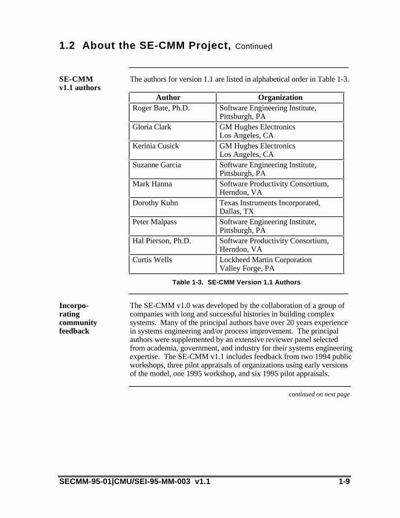
The authors for version 1.1 are listed in alphabetical order in Table 1-3.
Author OrganizationRoger Bate, Ph.D. Software Engineering Institute,
Pittsburgh, PAGloria Clark GM Hughes Electronics
Los Angeles, CAKerinia Cusick GM Hughes Electronics
Los Angeles, CASuzanne Garcia Software Engineering Institute,
Pittsburgh, PAMark Hanna Software Productivity Consortium,
Herndon, VADorothy Kuhn Texas Instruments Incorporated,
Dallas, TXPeter Malpass Software Engineering Institute,
Pittsburgh, PAHal Pierson, Ph.D. Software Productivity Consortium,
Herndon, VACurtis Wells Lockheed Martin Corporation
Valley Forge, PA
Table 1-3. SE-CMM Version 1.1 Authors
The SE-CMM v1.0 was developed by the collaboration of a group ofcompanies with long and successful histories in building complexsystems. Many of the principal authors have over 20 years experiencein systems engineering and/or process improvement. The principalauthors were supplemented by an extensive reviewer panel selectedfrom academia, government, and industry for their systems engineeringexpertise. The SE-CMM v1.1 includes feedback from two 1994 publicworkshops, three pilot appraisals of organizations using early versionsof the model, one 1995 workshop, and six 1995 pilot appraisals.
Incorpo-ratingcommunityfeedback
continued on next page
SECMM-95-01|CMU/SEI-95-MM-003 v1.1 1-9

1.2 About the SE-CMM Project, Continued
Changesfrom Version1.0
Changes reflected in Version 1.1 of the SE-CMM are driven by the SE-CMM requirement (3.1) to achieve industry acceptance. (SE-CMMrequirements can be found in Appendix B.) In the revision, weaddressed comments received from industry and government and aworkshop held in September 1995; specific changes include thefollowing:
• Increase the scope of the model to better address the life cycle aspectsof the system.
• Add a new process area to address the coordination of suppliercontributions.
• Clarify the generic practices.• Add to the base practice descriptive model.• Improve the Model Overview chapter.• Increase the emphasis on production and operations input into
development practices.
This version of the SE-CMM addresses the process aspects of systemsengineering and the product development portion of the life cycle. Thereare several possible avenues for future work which are being consideredby the steering group. They include
Future plansoutline
• Develop an integrated product development (IPD) framework thataddresses common and unique aspects of IPD in relation to thesystems engineering concepts embodied in the SE-CMM. This workwas begun in 1995 and continues in 1996.
• Extend the model into addressing the people and technology aspectsof product development.
Pilot appraisals of the SE-CMM continued throughout 1995, for a totalof nine appraisals conducted. Given the success of the pilot appraisals,EPIC expects to end their piloting in early 1996. At present, two firmsare available to assist organizations in conducting self-appraisals. Moresuch firms may become available.
1-10 SECMM-95-01|CMU/SEI-95-MM-003 v1.1
Chapter 2: Overview of the SE-CMM
The purpose of this chapter is to provide an overview of the conceptsand constructs used in the SE-CMM. It provides information on therequirements that led to the design of the SE-CMM, a description of thearchitecture, and a section on key concepts and terms which are helpfulin understanding the model. It serves as an introduction to the detaileddiscussion of the model in Chapter 4.
Purpose ofthis chapter
The following table provides a guide to the information found in thischapter.
In thischapter
Topic See Page
2.1 SE-CMM Foundations 2-2
2.2 Key Concepts of the SE-CMM 2-8
2.3 SE-CMM Architecture Description 2-14
2.4 Process Capability Aspect of the SE-CMM
2-21
2.5 Capability Levels 2-25
2.6 Domain Aspect of the SE-CMM 2-27
2.7 A Path for Improving SystemsEngineering Maturity
2-34
SECMM-95-01|CMU/SEI-95-MM-003 v1.1 2-1

2.1 SE-CMM Foundations
In this section, the fundamental concepts that have guided thedevelopment of the SE-CMM are presented. The SE-CMMrequirements and their traceability can be found in Appendix B.
Introduction
The SE-CMM Project believes that the quality of a product is a directfunction of (at least) the process and technology used to develop theproduct and the capability of the people assigned to do the work (seeFigure 2-1, below). The initial efforts of the project focus on modelingcharacteristics of the process dimension, that is, processes used toimplement and institutionalize sound systems engineering practiceswithin an organization. The SE-CMM Project believes that the qualityof a product is a direct function of the process capability, the technologycapability, and the people capability used to develop the product.
Criticaldimensions ofcapability
Product/Service
Capability
People TechnologyProcess
Quality
Figure 2-1. Critical Dimensions of Organizational Capability
continued on next page
2-2 SECMM-95-01|CMU/SEI-95-MM-003 v1.1

2.1 SE-CMM Foundations, Continued
There are several reasons that process is the first dimension oforganizational capability addressed by the SE-CMM. A few of theseinclude
Why processfirst?
• Process is an integrating function for people and technology.• Process focus improves predictability of performance, as well as
performance itself.• Research in improving process capability translates well from other
fields, such as software engineering, to systems engineering.
There are dozens of definitions of systems engineering published invarious industry, academic, and government documents that addresssystems engineering topics. Rather than invent an additional definition,the authors chose to adopt the definition found in Army Field Manual770-78, which reads as follows:
Systems engineering is the selective application of scientific andengineering efforts to
Definition ofsystemsengineering
• transform an operational need into a description of the systemconfiguration which best satisfies the operational need according to themeasures of effectiveness;
• integrate related technical parameters and ensure compatibility of allphysical, functional, and technical program interfaces in a mannerwhich optimizes the total system definition and design;
• integrate the efforts of all engineering disciplines and specialties intothe total engineering effort [FM 770-78].
This definition was adopted over others primarily because it emphasizesthe leadership role of system engineering in integrating other disciplinesand does not contain terminology specific to a particular industrysegment.
Why thisdefinition?
SE-CMM coverage extends to, but does not include, variouscomponent implementation disciplines (e.g., hardware, firmware, andsoftware development) and specialty engineering disciplines. Version1.1 of the model covers the total system life cycle.
Depth andbreadth ofmodelcoverage
continued on next page
SECMM-95-01|CMU/SEI-95-MM-003 v1.1 2-3

2.1 SE-CMM Foundations, Continued
The SE-CMM does not specifically address specialty engineeringdisciplines such as reliability, human factors engineering, ormanufacturing engineering. The model requires the integration of theengineering disciplines and specialties, whichever ones are necessaryand appropriate for a particular product development.
The issue of whether specialty engineering should be more directlyaddressed in the SE-CMM (e.g., via additional process areas) has beendebated at both the 1994 and 1995 SE-CMM workshops. Theconsensus at the 1995 workshop was that creating process areas forspecific specialties in the SE-CMM would not serve the communitieswho work in those areas and that making improvements to IntegrateDisciplines process area (PA04) was a better solution. The authorsaccepted this advice and have increased the descriptive language relatedto specialties, but did not add any new process areas.
Specialtyengineeringdisciplines
There is considerable debate within the systems engineering communityas to systems engineering's role within the overall management of aproject or program. Some argue that the systems engineering roleencompasses all the program management functions. Systemsengineering must have sufficient control over all the resources that arecritical to balancing cost, schedule, quality, and functionality objectives.Others argue that the systems engineering role should be subservient toprogram management, to be able to provide the necessary engineeringviewpoint into business decisions. The SE-CMM has taken the latterapproach, although it recognizes that systems engineers commonlyperform extensive program/project management roles in someenvironments. The project management practices expressed in theSE-CMM are those most commonly found as part of the technicalmanagement function of the systems engineer, and those supportingpractices that are critical to the successful performance of systemsengineering regardless of performer.
Relationshipof systemsengineering tooverallprogram/projectmanagement
The model architecture, shown in Figure 2-2, below, separates systemsengineering process areas (on the domain side) from genericcharacteristics (on the capability side) related to increasing processcapability (See Section 2.3 for a more detailed description). Thisarchitecture, which separates domain-specific characteristics fromcapability-related characteristics, was deliberately chosen to enable theuse of process capability criteria in other domain areas, e.g., softwareengineering. It also supports the expansion of the model into specialtyengineering or other component engineering disciplines, should this bedeemed appropriate by the organization using the model.
Flexiblearchitecture
2-4 SECMM-95-01|CMU/SEI-95-MM-003 v1.1

continued on next page
SECMM-95-01|CMU/SEI-95-MM-003 v1.1 2-5
2.1 SE-CMM Foundations, Continued
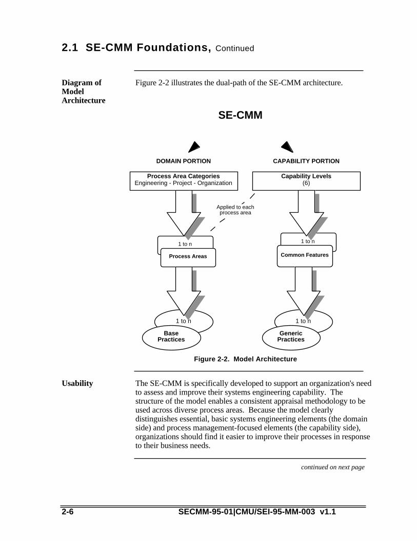
Figure 2-2 illustrates the dual-path of the SE-CMM architecture.Diagram ofModelArchitecture
Capability Levels(6)
Process Area CategoriesEngineering - Project - Organization
DOMAIN PORTION CAPABILITY PORTION
1 to n
Process Areas
1 to n
Common Features
1 to n
BasePractices
1 to n
GenericPractices
Applied to eachprocess area
SE-CMM
Figure 2-2. Model Architecture
The SE-CMM is specifically developed to support an organization's needto assess and improve their systems engineering capability. Thestructure of the model enables a consistent appraisal methodology to beused across diverse process areas. Because the model clearlydistinguishes essential, basic systems engineering elements (the domainside) and process management-focused elements (the capability side),organizations should find it easier to improve their processes in responseto their business needs.
Usability
continued on next page
2-6 SECMM-95-01|CMU/SEI-95-MM-003 v1.1

2.1 SE-CMM Foundations, Continued
The SE-CMM has a wide range of applicability. The SE-CMM wasdeveloped to be valuable to market-driven project environments as wellas negotiated-contract environments. By providing a multipurpose assetthat can be used by (1) individual systems engineering practitioners as aguide, (2) their parent organizations for productivity improvement, and(3) any organization as an eventual supplier selection tool, the SE-CMMmeets the needs of a wide range of users. Applicability will beenhanced by incorporating changes from applying the model.
Range ofapplicability
One of the design goals of the SE-CMM effort was to capture thesalient concepts from emerging standards and initiatives (e.g., ISO9001, draft MIL-STD- 499B [now being revised as EIA IS-632], IEEEP1220) and existing models. SE-CMM-94-09|CMU/SEI-94-TR-26,Relationships Between the SE-CMM and Other Products, provides across-reference between the SE-CMM and some of these standards andmodels.
Capture andgain leveragefrom existing& emergingstandards
Although the architecture and syntax used to express the SE-CMMmodel are different from those used in the CMM for Software v1.1, itis envisioned that these two models can be used together effectively toimprove and assess the systems and software engineering processes ofa project or organization. SECMM-94-09|CMU/SEI-94-TR-26,Relationship Between the SE-CMM and Other Products, containsinformation on this interface.
Retain CMMinterface
continued on next page
SECMM-95-01|CMU/SEI-95-MM-003 v1.1 2-7

2.1 SE-CMM Foundations, Continued
Figure 2-3 illustrates the intended relationship of the SE-CMM to anorganization's process design and improvement activities. TheSE-CMM does not intend to imply or prescribe organizational issuessuch as organizational culture, role definitions, or structure, nor is itintended to imply any particular product or project context. Itestablishes characteristics essential to good systems engineering, butdoes not imply or define a specific, executable process. The majorimplication of this approach is that the SE-CMM will enhance theresulting systems engineering processes without necessarily drivingchanges in culture or products. This approach supports the desire to usethe SE-CMM in a wide spectrum of organizational contexts.
SE-CMMapplicationenvironment
• Design
• Development
• Validation and Verification
Organization’sSystems Engineering
Process Development
OrganizationalFactors
• Culture• Size• Structure• Roles
Business Factors
• Strategic Focus• Market Pull vs.
Technology Push• Contract vs.
Market Driven• Technology/Method
Support
SE-CMM
• Focus Area (Domain)
• Capability• Support
Guidance
Figure 2-3. Focus of the SE-CMM
2-8 SECMM-95-01|CMU/SEI-95-MM-003 v1.1

2.2 Key Concepts of the SE-CMM
In the discussions above, and those which follow, terms are used andconcepts are introduced that have particular meaning within the context ofthe SE-CMM. This section elaborates those concepts that are critical toeffective understanding, interpretation, and use of the SE-CMM. Someconcepts specific to the model, such as "generic practice" and "basepractice," are defined and discussed in the sections of the modeldescription that address them. Other terms and concepts are defined in theglossary (Appendix D). The concepts to be discussed in this section arelisted below:
Introduction
• organization• project• system• work product• customer• process• systems engineering process• process area• role independence• process capability• institutionalization• process management• capability maturity model
Two terms are used within the SE-CMM to differentiate aspects oforganizational structure: organization and project. The authors realizethat other constructs, such as teams, exist within business entities, butthere is no commonly accepted terminology that spans all businesscontexts. These two terms were chosen because they are commonlyused/understood by most of the anticipated audience of the SE-CMM.
Organizationsand projects
For the purposes of the SE-CMM, an organization is defined as a unitwithin a company, the whole company or other entity (e.g., governmentagency or branch of service), within which many projects are managedas a whole. All projects within an organization typically share commonpolicies at the top of the reporting structure. An organization mayconsist of co-located or geographically distributed projects andsupporting infrastructures.
The term "organization" is used to connote an infrastructure to supportcommon strategic, business, and process-related functions. Theinfrastructure exists and must be maintained for the business to beeffective in producing, delivering, supporting, and marketing itsproducts.
Organization
SECMM-95-01|CMU/SEI-95-MM-003 v1.1 2-9

continued on next page
2-10 SECMM-95-01|CMU/SEI-95-MM-003 v1.1

2.2 Key Concepts of the SE-CMM, Continued
The project is the aggregate of effort and other resources focused ondeveloping and/or maintaining a specific product. The product mayinclude hardware, software, and other components. Typically a projecthas its own funding, cost accounting, and delivery schedule. A projectmay constitute an organizational entity of its own, or it may bestructured as a team, task force, or other entity used by the organizationto produce products.
The process areas in the domain side of the SE-CMM have beendivided into three categories, engineering, project, and organization, asdiscussed in Section 2.6. The categories of organization and project aredistinguished based on typical ownership. The SE-CMM differentiatesbetween project and organization categories by defining the project asfocused on a specific product, versus the organization whichencompasses one or more projects.
Project
A system can be defined as
• an integrated composite of people, products, and processes thatprovide a capability to satisfy a need or objective [MIL-STD-499B]
• an assembly of things or parts forming a complex or unitary whole; acollection of components organized to accomplish a specific functionor set of functions
• an interacting combination of elements, viewed in relation to function[INCOSE 95]
A system may be a product that is hardware only, hardware/software,software only, or a service. The term “system” is used throughout themodel to indicate the sum of the products being delivered to thecustomer(s) or user(s) of the products. Denoting a product as a systemis an acknowledgment of the need to treat all the elements of the productand their interfaces in a disciplined and systematic way, so as to achievethe overall cost, schedule, and performance objectives of the businessentity developing the product.
System
continued on next page
SECMM-95-01|CMU/SEI-95-MM-003 v1.1 2-11

2.2 Key Concepts of the SE-CMM, Continued
Work products are all the documents, files, data, etc., generated in thecourse of performing any process. For example, work products of areview activity might be action item lists, whereas work products of arequirements process might be a database file containing all theelaborated requirements for the product. Rather than call out individualwork products for each process area, the SE-CMM lists "typical workproducts" of a particular base practice, to elaborate further the intendedscope of that base practice. These lists are not to be construed as"mandatory" work products; they are illustrative only, and reflect arange of organizational and product contexts.
Workproduct
A customer is the individual(s) or entity for whom a product isdeveloped or service is rendered, and/or the individual or entity whouses the product or service.
In the context of the SE-CMM, a customer may be either negotiated ornon-negotiated. A negotiated customer is an individual or entity whocontracts with another entity to produce a specific product or set ofproducts according to a set of specifications provided by the customer.A non-negotiated, or market-driven, customer is one of manyindividuals or business entities who have a real or perceived need for aproduct. The customer may also be represented by a customersurrogate such as marketing or product focus groups.
Customer
In most cases, the SE-CMM uses the term customer in the singular, asa grammatical convenience. However, the SE-CMM does intend toinclude the case of multiple customers.
Note that, in the context of the SE-CMM, the individual or entity usingthe product or service is also included in the notion of customer. This isrelevant in the case of negotiated customers, since the entity to whomthe product is delivered is not always the entity or individual who willactually use the product or service. The concept and usage of customerin the SE-CMM is intended to recognize the responsibility of thesystems engineering function to address the entire concept of customer,which includes the user.
continued on next page
2-12 SECMM-95-01|CMU/SEI-95-MM-003 v1.1
2.2 Key Concepts of the SE-CMM, Continued
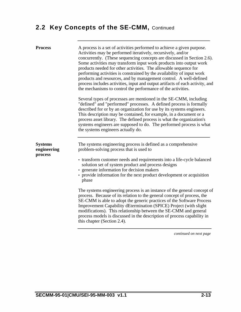
A process is a set of activities performed to achieve a given purpose.Activities may be performed iteratively, recursively, and/orconcurrently. (These sequencing concepts are discussed in Section 2.6).Some activities may transform input work products into output workproducts needed for other activities. The allowable sequence forperforming activities is constrained by the availability of input workproducts and resources, and by management control. A well-definedprocess includes activities, input and output artifacts of each activity, andthe mechanisms to control the performance of the activities.
Several types of processes are mentioned in the SE-CMM, including"defined" and "performed" processes. A defined process is formallydescribed for or by an organization for use by its systems engineers.This description may be contained, for example, in a document or aprocess asset library. The defined process is what the organization'ssystems engineers are supposed to do. The performed process is whatthe systems engineers actually do.
Process
The systems engineering process is defined as a comprehensiveproblem-solving process that is used to
Systemsengineeringprocess
• transform customer needs and requirements into a life-cycle balancedsolution set of system product and process designs
• generate information for decision makers• provide information for the next product development or acquisition
phase
The systems engineering process is an instance of the general concept ofprocess. Because of its relation to the general concept of process, theSE-CMM is able to adopt the generic practices of the Software ProcessImprovement Capability dEtermination (SPICE) Project (with slightmodifications). This relationship between the SE-CMM and generalprocess models is discussed in the description of process capability inthis chapter (Section 2.4).
continued on next page
SECMM-95-01|CMU/SEI-95-MM-003 v1.1 2-13

2.2 Key Concepts of the SE-CMM, Continued
A process area (PA) is a defined set of related systems engineeringprocess characteristics, which, when performed collectively, can achievea defined purpose.
The process areas are composed of base practices, which are mandatorycharacteristics that must exist within an organization's implementedsystems engineering process for the organization to claim satisfaction ofthat PA.
Process area
The process areas of the SE-CMM are groups of practices that, whentaken together, achieve a common purpose. However, the groupingsare not intended to imply that all the base practices of a process arenecessarily performed by a single individual or role. All base practicesare written in verb-object format (i.e., without a specific subject) so as tominimize the perception that a particular base practice "belongs to" aparticular role. This is one way in which the syntax of the modelsupports its use across a wide spectrum of organizational contexts.
Roleindependence
Process capability is defined as the quantifiable range of expected resultsthat can be achieved by following a process. The SE-CMM AppraisalMethod (SAM), which can be used to determine process capabilitylevels for each process area within a project or organization, is basedupon statistical process control concepts which define the use ofprocess capability in many industrial environments. (The appraisalmethod is further described in Section 3.2) The capability side of theSE-CMM reflects these concepts and provides guidance in improvingthe process capability of the systems engineering practices which arereferenced in the domain side of the SE-CMM.
The capability of an organization's process helps to predict a project'sability to meet its goals. Projects in low capability organizationsexperience wide variations in achieving cost, schedule, functionality, andquality targets. These concepts are further discussed in Chapter 3.
Processcapability
continued on next page
2-14 SECMM-95-01|CMU/SEI-95-MM-003 v1.1
2.2 Key Concepts of the SE-CMM, Continued
Institutionalization is the building of infrastructure and corporate culturethat support methods, practices, and procedures so that they are theongoing way of doing business, even after those who originally definedthem are gone. The process capability side of the SE-CMM supportsinstitutionalization by providing practices and a path toward quantitativemanagement and continuous improvement. In this way, the SE-CMMasserts that the organization needs to explicitly support processdefinition, management, and improvement. Institutionalization providesa path toward gaining maximum benefit from a process that exhibitssound systems engineering characteristics.
Institution-alization
Process management is the set of activities and infrastructures used topredict, evaluate, and control the performance of a process. Processmanagement implies that a process is defined (since one cannot predictor control something that is undefined). The focus on processmanagement implies that a project or organization takes into accountboth product- and process-related factors in planning, performance,evaluation, monitoring, and corrective action.
Processmanagement
A capability maturity model such as the SE-CMM describes the stagesthrough which processes progress as they are defined, implemented,and improved. The model provides a guide for selecting processimprovement strategies by determining the current capabilities ofspecific processes and identifying the issues most critical to quality andprocess improvement within a particular domain, such as softwareengineering or systems engineering. A capability maturity model(CMM) may take the form of a reference model to be used as a guidefor developing and improving a mature, defined process.
A CMM may also be used to appraise the existence andinstitutionalization of a defined process that implements the referencedpractices. A capability maturity model can cover the processes used toperform the tasks of the specified domain, (e.g., systems engineering).In addition, a CMM can cover the processes used to ensure effectivedevelopment and use of human resources, and the insertion ofappropriate technology into the products and into the tools used toproduce the products. The latter aspects have not yet been elaborated forsystems engineering.
Capabilitymaturitymodel
SECMM-95-01|CMU/SEI-95-MM-003 v1.1 2-15
2.3 SE-CMM Architecture Description
Figure 2-4 illustrates the architecture of the model and provides thebasis for the discussion in this section. Each of the major componentsof the model is briefly discussed, and intended interactions between theaspects of the model are introduced. Details of each aspect of the modelare covered in the sections, Process Capability Aspect of the SE-CMMand Domain Aspect of the SE-CMM, found later in this chapter.
Introduction
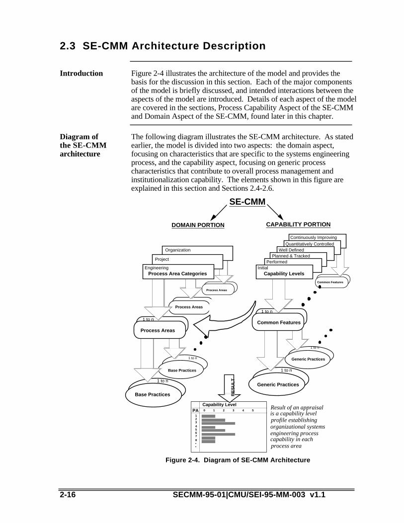
The following diagram illustrates the SE-CMM architecture. As statedearlier, the model is divided into two aspects: the domain aspect,focusing on characteristics that are specific to the systems engineeringprocess, and the capability aspect, focusing on generic processcharacteristics that contribute to overall process management andinstitutionalization capability. The elements shown in this figure areexplained in this section and Sections 2.4-2.6.
Diagram ofthe SE-CMMarchitecture
Generic Practices
1 to n
Common Features
Base Practices
1 to n
Process Areas
Process Areas
PerformedPlanned & Tracked
Well DefinedQuantitatively Controlled
Continuously Improving
Generic Practices
1 to n
Common Features
1 to n
Organization
Base Practices
1 to n
Process Areas
1 to n
Project
Process Area CategoriesEngineering
Capability LevelsInitial
PACapability Level0 1 2 3 4 5
12345678••
Result of an appraisal is a capability level profile establishing organizational systems engineering process capability in each process area
DOMAIN PORTION CAPABILITY PORTIONR
ES
UL
T
SE-CMM
Figure 2-4. Diagram of SE-CMM Architecture
2-16 SECMM-95-01|CMU/SEI-95-MM-003 v1.1

continued on next page
SECMM-95-01|CMU/SEI-95-MM-003 v1.1 2-17

2.3 SE-CMM Architecture Description,Continued
The dual-path architecture shown in Figure 2-4 was adopted with onlyslight modification from an early version of the model chosen by theSPICE Project's Baseline Practices Guide. This approach was deemedparticularly applicable to the SE-CMM because it clearly separates basiccharacteristics of the systems engineering process (the domain aspect)from process management and institutionalization characteristics of thesystems engineering process (capability aspect).
Dual-patharchitecture
Table 2-1 contains the basic definitions of the components of thecapability aspect of the SE-CMM. They are further explained in theprocess capability section (Section 2.4), as well as elaborated in Chapter4a.
Architecturalcomponents ofthe capabilityaspect
ArchitecturalComponent Definition Example
Capability Level A set of commonfeatures (sets ofactivities) that worktogether to providea majorenhancement in thecapability toperform a process(SPICE)
2 Planned andTracked
CommonFeature
A set of practicesthat address thesame aspect ofprocessmanagement orinstitutionalization(SPICE)
2.1 Planningperformance
Generic Practice An implementationorinstitutionalizationpractice thatenhances thecapability toperform anyprocess (SPICE)
2.1.3 Documentthe process.Document theapproach toperforming theprocess area instandardsand/orprocedures
Table 2-1. Components of the Process Capability Aspect of the SE-CMM
2-18 SECMM-95-01|CMU/SEI-95-MM-003 v1.1

continued on next page
SECMM-95-01|CMU/SEI-95-MM-003 v1.1 2-19

2.3 SE-CMM Architecture Description,Continued
The SE-CMM groups process capability in three tiers: capability levels,common features, and generic practices. The capability levels indicateincreasing levels of process maturity and are composed of one or morecommon features. Each common feature is further detailed by severalgeneric practices.
The common features are designed to describe major shifts in anorganization's characteristic manner of performing work processes (inthis case, the systems engineering domain). Each common feature hasone or more generic practices. With one exception, the generic practicescan be applied to each of the process areas (from the domain side of theSE-CMM) in addition to the basic performance of the practice. The oneexception is the first common feature, "Base practices are performed."
The first capability level has only one generic practice. It is the "do it"generic practice. It asks, "Does someone in your environment do eachof the base practices as a part of their process for accomplishing thekind of work described in this process area?" Answering "yes" to thisquestion for each base practice of a process area means that the processarea is informally performed (level 1).
The subsequent common features have generic practices that helpdetermine how well a project manages and improves each process areaas a whole. The generic practices, described in Chapter 4A, are groupedto emphasize any major shift in an organization's characteristic mannerof doing systems engineering.
The processcapabilityaspect of theSE-CMM
continued on next page
2-20 SECMM-95-01|CMU/SEI-95-MM-003 v1.1

2.3 SE-CMM Architecture Description,Continued
Table 2-2 lists the capability levels and common features of thecapability aspect of the SE-CMM.
Capabilitylevels
CapabilityLevel Common Features
ContinuouslyImproving
• Improving organizational capability
• Improving process effectiveness
QuantitativelyControlled
• Establishing measurable quality goals
• Objectively managing performance
Well Defined • Defining a standard process
• Perform the standard process
Planned andTracked
• Planning performance
• Disciplined performance
• Verifying performance
• Tracking performance
PerformedInformally
• Base practices performed
Table 2-2. SE-CMM Capability Levels
Derivedrequirements
Because the architecture for the model was not expressed in the projectrequirements, there are several areas where, based on the selectedarchitecture, we developed derived requirements that address particularsimplied by the SPICE architecture. These derived requirements reflectmostly issues such as criteria for including/excluding process areas, orcriteria for base or generic practices.
The following criteria express the derived requirements for a genericpractice
• A generic practice can be applied to all process areas.• Only one generic practice is necessary to achieve a Level 1 in each
process area (i.e., generic practice 1.1, Perform the Practice.).• Redundancy with base practices is allowed for special emphasis.• Practices that are essential to a given level of process capability are
included.• Where generic practice topics overlap with process area topics, the
generic practice focuses on the deployment and management aspect ofthe topic.
Derivedrequirementsfor genericpractices
SECMM-95-01|CMU/SEI-95-MM-003 v1.1 2-21

continued on next page
2-22 SECMM-95-01|CMU/SEI-95-MM-003 v1.1

2.3 SE-CMM Architecture Description,Continued
The SE-CMM characterizes the systems engineering domain by usingprocess areas. Each process area is further detailed by several basepractices and explanatory notes. There are 18 process areas, which aregrouped into 3 process categories: engineering, project, andorganization.
The 18 process areas are designed to describe the major topic areasessential to effective systems engineering within an organization. Inyour home organization, your process will include base practices fromthe process areas that are executed by (or primarily by) individuals inthe role of systems engineers. These are the practices primarily groupedin the engineering category. Other process areas may be included inprocesses that are executed by people who are performing other roles.These are the project and organization process areas, which can also bethought of as support process areas.
The authors included support process areas in the SE-CMM becauseeffective systems engineering is unlikely unless these support tasks areperformed. For example, it is unlikely that effective systemsengineering will be executed if no one ensures that all the engineeringstaff is working to the same requirement and design baselines at a givenperiod in time (an aspect of the Manage Configurations process area).The point of the SE-CMM is not to indicate "who" does the kinds ofthings described in a particular process area, but to indicate that the workneeds to be performed by someone regardless of their role.
The domainaspect of theSE-CMM
Table 2-3 contains the basic definitions of the components of thedomain aspect of the SE-CMM.
Architecturalcomponents ofthe domainaspect
ArchitecturalComponent Definition
Process Category A set of process areas addressing the samegeneral area of activity
Process Area A set of related practices, which whenperformed collectively, can achieve thepurpose of the process area (SPICE)
Base Practice An engineering or management practice(activity) that addresses the purpose of aparticular process area and thus belongs toit (SPICE)
Table 2-3. Components of the Domain Aspect of the SE-CMM
SECMM-95-01|CMU/SEI-95-MM-003 v1.1 2-23

continued on next page
2-24 SECMM-95-01|CMU/SEI-95-MM-003 v1.1

2.3 SE-CMM Architecture Description,Continued
Table 2-4 lists the 18 process areas. To emphasize that the SE-CMMdoes not prescribe a specific process or sequence, the process areas arearranged alphabetically by title within each group.
Process areasof the domainaspect
EngineeringProcessAreas
ProjectProcessAreas
OrganizationalProcessAreas
Analyze CandidateSolutions
Ensure Quality Coordinate withSuppliers
Derive and AllocateRequirements
ManageConfigurations
Define Organization'sSystems EngineeringProcess
Evolve SystemArchitecture
Manage Risk Improve Organization'sSystems EngineeringProcesses
Integrate Disciplines Monitor andControlTechnical Effort
Manage Product LineEvolution
Integrate System Plan TechnicalEffort
Manage SystemsEngineering SupportEnvironment
Understand CustomerNeeds andExpectations
Provide OngoingKnowledge and Skills
Verify and ValidateSystem
Table 2-4. SE-CMM Process Areas
continued on next page
SECMM-95-01|CMU/SEI-95-MM-003 v1.1 2-25
2.3 SE-CMM Architecture Description,Continued
The SE-CMM process areas provide complete coverage of the life cycleof the system. This life-cycle coverage stems in part from therecognition that the same basic systems engineering activities areappropriately applied to each product life-cycle phase. The key aspect ofdetecting when each activity should be addressed for a given phase isaddressed in the Ensure Quality process area (PA08).
Life-cyclecoverage
In developing the model, the authors needed to determine the basis forincluding or not including a process area within the model. Thefollowing criteria were developed for evaluating if a process area shouldbe included:
• The process area is essential for effective systems engineering to existwithin an organization.
• The process area's purpose is not addressed sufficiently in the genericpractices.
• The process area's purpose is considered too important by the authorteam to be left out.
• The process area assembles key concepts in one area for ease of use.
Process arearequirements
The following criteria express the derived requirements for a basepractice:
• The base practice is considered by the authors to be essential to thepractice of good systems engineering.
• The base practice is considered by the authors to be essential toachieve a capability level 1 within that process area.
• Redundancy with generic practices is allowed for special emphasis.• Where base practice and generic practice topics overlap, the base
practice focuses on the performance of the primary activities related tothe topic.
Derivedrequirementsfor basepractices
2-26 SECMM-95-01|CMU/SEI-95-MM-003 v1.1

2.4 Process Capability Aspect of the SE-CMM
There are dozens of sources of theory and practice that describe thebenefits of improving process capability. (See the bibliography in theCMM for Software v1.1 [Paulk 93a] for a starter list.) For mostorganizations, the ability to estimate and predict accurately the results oftheir product development activities from a viewpoint of cost, schedule,and quality is a fundamental business goal. Case studies from thesoftware engineering community and elsewhere suggest that addressingissues of process management, measurement, and institutionalizationimprove the organization's ability to meet its cost, quality, and schedulegoals [Herbsleb 94].
Why addressprocesscapability?
As experience in applying process improvement principles in differentenvironments has evolved, principles that contribute significantly toincreasing capability have been noted and analyzed. The separation ofthe process capability practices from domain-specific practices asdescribed in the previous section, provides two major benefits:
• Most product development activities encompass many disciplines anddomains. The ability to use a set of focused process improvementprinciples as a guide for appraisal and improvement across thosedisciplines improves communication among them, and providesleveraging opportunities which are not present if the principles areembedded in discipline-specific expressions of capability, such asoccurs in the CMM for Software v1.1.
Why isprocesscapabilityseparatedfrom theprocessareas?
• The separation of process capability practices from domain-specificpractices provides an opportunity for guidance that transcendsorganizational and role-based boundaries. For example, the commonfeature on planning performance can be applied before the commonfeature on verifying performance. These common features, asdetailed by their generic practices, are clearly independent of businessarea and application domain. This improves communication andadoption of these principles across a wide spectrum of industries.
continued on next page
SECMM-95-01|CMU/SEI-95-MM-003 v1.1 2-27

2.4 Process Capability Aspect of the SE-CMM,Continued
The following diagram illustrates the improvement path adopted by theSE-CMM Project.
Processcapabilitylevel diagram
NOTPERFORMED
PERFORMED INFORMALLY • Base practicesperformed
PLANNED & TRACKED
• Committing to perform
• Planning performance
• Disciplined performance
•Tracking performance • Verifying performance
01
23
45
WELL-DEFINED
• Defining a standard process
•Tailoring the standard process
• Using data• Perform the defined process
QUANTITATIVELY CONTROLLED
• Establishing measurable quality goals
• Determining process capability to achieve goals
• Objectively managing performance
CONTINUOUSLY IMPROVING
• Establishing quantitative process effectiveness goals
• Improving process effectiveness
Figure 2-5. Improvement Path for Process Capability
continued on next page
2-28 SECMM-95-01|CMU/SEI-95-MM-003 v1.1

2.4 Process Capability Aspect of the SE-CMM,Continued
SECMM-95-01|CMU/SEI-95-MM-003 v1.1 2-29

Why groupcommonfeatures bycapabilitylevel?
By their nature, there is more than one way to group practices intocommon features and common features into capability levels.
In order to separate "how well you do something" from "what you do,"the SE-CMM based its approach on an early version of the SPICEBaseline Practices Guide.
The following discussion addresses these common features.
The ordering of the common features stems from the observation thatimplementation and institutionalization of some practices benefit fromthe presence of others. This is especially true if practices are wellestablished. Before an organization can define, tailor, and use a processeffectively, individual projects should have some experience managingthe performance of that process. For example, before institutionalizinga specific estimation process for an entire organization, the organizationshould first attempt to use the estimation process on a project.However, some aspects of process implementation andinstitutionalization should be considered together (not one orderedbefore the other) since they work together toward enhancing capability.
Common features and capability levels are important both inperforming an assessment and improving an organization's processcapability. In the case of an assessment where an organization hassome, but not all common features implemented at a particularcapability level for a particular process, the organization usually isoperating at the lowest completed capability level for that process. Forexample, at capability level 2, if the Tracking Performance commonfeature is lacking, it will be difficult to track project performance. If acommon feature is in place, but not all its preceding ones (i.e., those atlower capability levels), the organization may not reap the full benefit ofhaving implemented that common feature. An assessment team shouldtake this into account in assessing an organization's individualprocesses.
In the case of improvement, organizing the practices into capabilitylevels provides an organization with an "improvement road map"should it desire to enhance its capability for a specific process. Forthese reasons, the practices in the SE-CMM are grouped into commonfeatures which are ordered by capability levels.
In either case, an assessment should be performed to determine thecapability levels for each of the process areas. This indicates thatdifferent process areas can and probably will exist at different levels ofcapability. The organization will then be able to use this process-specific information as a means to focus improvements to itsprocesses. The priority and sequence of the organization's activities toimprove its processes should take into account its business goals.
continued on next page
2-30 SECMM-95-01|CMU/SEI-95-MM-003 v1.1

2.4 Process Capability Aspect of the SE-CMM,Continued
Common features are groupings of generic practices appropriate withincapability levels. For example, common features included in thePlanned and Tracked level (Level 2) are Planning Performance,Disciplined Performance, Tracking Performance, and VerifyingPerformance. An expansion of each feature is provided in Chapter 4A.See Table 2-2 for a complete list of common features.
Commonfeatures
Generic practices are a series of activities that apply to all processes.They address the management, measurement, and institutionalizationaspects of a process. In general, they are used during an appraisal todetermine the capability of any process. Generic practices are, asmentioned earlier, grouped by common feature and capability level.
Genericpractices
The SE-CMM addresses measurement in two ways. On the capabilityside, the definition of a standard process or process family necessitatesthe incorporation of measurement. At capability level 2, the genericpractice Track with Measurement emphasizes the use of measurementin tracking the use of a process. The common feature EstablishingMeasurable Quality Goals adds emphasis in terms of quantitativequality goals for higher levels of maturity.
On the domain side, the process areas Plan Technical Effort (PA12) andMonitor and Control Technical Effort (PA11) describe basicmeasurements that support systems engineering. The base practices ofthe Ensure Quality process area (PA08) describe measurement of thequality of the systems engineering process and of the work products ofall the process areas. References to measurement and measurement-related issues are embedded within the SE-CMM rather than addressedseparately to emphasize the integration of measurement into theactivities and processes being described or performed.
A note onmeasurementthroughout theSE-CMM
SECMM-95-01|CMU/SEI-95-MM-003 v1.1 2-31
2.5 Capability Levels
This section describes the six capability levels to provide the reader witha sense of the changes that would be expected as a process within aproject or organization increases in capability.
Introduction
The Not Performed level (Level 0) displays no common features. It ischaracteristic of an organization just entering the systems engineeringfield, or one that has not focused on the systematic application ofsystems engineering principles in their product development. Theyaccomplish some of the tasks, but are not necessarily sure how.Performance is not generally consistent, particularly if key individualsare absent or the tasks become more complex.
The Not Performed level has no common features. There is generalfailure to perform the base practices in the process area. Where thereare work products that result from performing the process, they are noteasily identifiable or accessible.
The NotPerformedlevel
At this level, all base practices are performed somewhere in the project'sor organization's implemented process. However, consistent planningand tracking of that performance is missing. Good performance,therefore, depends on individual knowledge and effort. Work productsare generally adequate, but quality and efficiency of production dependon how well individuals within the organization perceive that tasksshould be performed. Based on experience, there is general assurancethat an action will be performed adequately when required. However,the capability to perform an activity is not generally repeatable ortransferable.
ThePerformedInformallylevel
At the Planned and Tracked level, planning and tracking have beenintroduced. There is general recognition that the organization'sperformance is dependent on how efficiently the systems engineeringbase practices are implemented within the project's or organization'sprocess. Therefore, work products related to base practiceimplementation are periodically reviewed and placed under versioncontrol. Corrective action is taken when indicated by variances in workproducts.
The primary distinction between the Performed Informally and thePlanned and Tracked levels is that at the Planned and Tracked level, theexecution of the base practices in the project's implemented process isplanned and managed. Therefore, it is repeatable within theimplementing project, though not necessarily transferable across theorganization.
The Planned& Trackedlevel
2-32 SECMM-95-01|CMU/SEI-95-MM-003 v1.1

continued on next page
SECMM-95-01|CMU/SEI-95-MM-003 v1.1 2-33
2.5 Capability Levels, Continued
At this level, base practices are performed throughout the organizationvia the use of approved, tailored versions of standard, documentedprocesses. Data from using the process are gathered and used todetermine if the process should be modified or improved. Thisinformation is used in planning and managing the day-to-day executionof multiple projects within the organization and is used for short- andlong-term process improvement.
The main difference between the Planned and Tacked and Well Definedlevels is the use of organization-wide, accepted standard processes thatimplement the characteristics exhibited by the base practices. Thecapability to perform an activity is, therefore, directly transferable tonew projects within the organization.
The WellDefined level
At the Quantitatively Controlled level, measurable process goals areestablished for each defined process and associated work products, anddetailed measures of performance are collected and analyzed. Thesedata enable quantitative understanding of the process and an improvedability to predict performance. Performance, then, is objectivelymanaged and defects are selectively identified and corrected.
TheQuantitativelyControlled level
This is the highest achievement level from the viewpoint of processcapability. The organization has established quantitative, as well asqualitative, goals for process effectiveness and efficiency, based onlong-range business strategies and goals. Continuous processimprovement toward achievement of these goals using timely,quantitative performance feedback has been established. Furtherenhancements are achieved by pilot testing of innovative ideas andplanned insertion of new technology.
TheContinuouslyImprovinglevel
2-34 SECMM-95-01|CMU/SEI-95-MM-003 v1.1

2.6 Domain Aspect of the SE-CMM
The domain aspect of the SE-CMM is a collection of essential elements,called base practices, that are grouped into process areas, as describedearlier. The seven process areas in the engineering category are shownbelow grouped within the organizational and project process areaswhich support their execution. How process areas were selected isdiscussed later in this section.
Context ofthe processareas
DefineOrganization’s
SE Process
Manage SE Support
Environment
ManageRisk
Ensure Quality
ManageProduct
Line Evolution
UnderstandCustomer
Needs
Derive & Allocate
Requirements AnalyzeCandidateSolutions
EvolveSystem
Architecture
IntegrateSystem
ImproveOrganization’sSE Processes
Monitor/ControlTechnical Effort
Plan Technical
Effort
ManageConfigurations
Verify &ValidateSystem
IntegrateDisciplines
Coordinatewith
Suppliers
ProvideOngoing Skills
andKnowledge
Figure 2-6. SE-CMM Process Areas
continued on next page
SECMM-95-01|CMU/SEI-95-MM-003 v1.1 2-35

2.6 Domain Aspect of the SE-CMM, Continued
The depiction of the process areas in Figure 2-6 without connectinglines is deliberate. It is meant to indicate that the process areas are not,by nature, chronologically established. While there is a logical initiationsequence, many are expected to be exhibited in the organization'sproduct development process several times during the development of aproduct. For example, requirements are developed and refined atseveral different levels during the system or product development lifecycle. The process area titled Derive and Allocate Requirements(PA02) would, therefore, be used as a guide to the implemented processwhenever the work product is one or more requirements document orfiles.
Logical vs.chrono-logicalarrangement
There are three process categories defined for the SE-CMM. They are
• engineering• project• organization
These three categories and their contents are discussed below. Theprocess areas in each category are described in detail in Chapter 4B.
Processcategories ofthe SE-CMM
The engineering category groups together those process areas that areprimarily concerned with the technical and engineering aspects ofproduct development. They are organized alphabetically within thecategory to discourage the reader from implying a particular sequencingof the process areas. They include
Process areasof theengineeringcategory
• Analyze Candidate Solutions• Derive and Allocate Requirements• Evolve System Architecture• Integrate Disciplines• Integrate System• Understand Customer Needs and Expectations• Verify and Validate system
continued on next page
2-36 SECMM-95-01|CMU/SEI-95-MM-003 v1.1

2.6 Domain Aspect of the SE-CMM, Continued
The project category groups together process areas that are primarilyconcerned with providing the technical management infrastructureneeded to develop a product successfully. Like the process areas in theengineering category, they are organized alphabetically. They include
Process areasof the projectcategory
• Ensure Quality• Manage Configurations• Manage Risk• Monitor and Control Technical Effort• Plan Technical Effort
The organization category groups together process areas that areprimarily concerned with providing a business infrastructure thatdirectly supports the needs of systems engineering, but that are usuallyfound concentrated at an organization, rather than a project level. Likethe other categories, they are organized alphabetically. They include
Process areasof theorganizationcategory
• Coordinate with Suppliers• Define Organization's Systems Engineering Process• Improve Organization's Systems Engineering Processes• Manage Product Line Evolution• Manage Systems Engineering Support Environment• Provide Ongoing Skills and Knowledge
continued on next page
SECMM-95-01|CMU/SEI-95-MM-003 v1.1 2-37

2.6 Domain Aspect of the SE-CMM, Continued
Especially when looking at the support process areas of the SE-CMM,questions often arise as to why certain process areas are included orexcluded from the model. Following is a brief discussion of therationale for including process areas about which the author team hasreceived such inquiries.
The process areas Manage Configurations (PA09) and ProvideOngoing Skills and Knowledge (PA17) were considered to be essentialfor effective systems engineering to exist within an organization, eventhough they may not be a primary systems engineering responsibility.The Plan Technical Effort process area (PA12) was included because itwas believed that the generic practices did not provide sufficientguidance to the model user to be of significant value. The EnsureQuality process area (PA08) was considered too important by theauthor team to leave out even though there was significant discussionthat the fundamental concepts were covered in the Define Organization'sSystems Engineering process area (PA13). The Manage Risk processarea (PA10) was included as a process area for ease of use, since theother alternative was to spread the concepts throughout the model,dispersing the practices throughout other process areas. The Coordinatewith Suppliers process area (PA18) was requested by September 1995workshop participants and companies contributing SE-CMM authors.
Rationale forinclusion ofselectedprocess areas
continued on next page
2-38 SECMM-95-01|CMU/SEI-95-MM-003 v1.1

2.6 Domain Aspect of the SE-CMM, Continued
Selecting the process areas to be included within the SE-CMM was acompromise between completeness and having a reasonable number ofprocess areas to deal with when improving and appraising processes.We selected process areas that are
• essential elements of systems engineering• crucial to the success of a systems engineering activity even if they are
not performed by systems engineering. For example, it would bedifficult to appraise a systems engineering activity without knowingwhether configuration management is consistently practiced andsupported.
• activities covered in the generic practices, but requiring more detailspecific to systems engineering
• common sources of difficulty in achieving quality results from thesystems engineering activities, and thus require special emphasis
• the subject of intense concerns among managers and are needed toensure that the area gets the amount of attention that management feelsis appropriate. One example of this type of process is the EnsureQuality process area (PA08), which is included to meet managementconcerns and to assemble in one area essential activities that are crucialto high-quality outputs of the projects' and organization’s processes.
Inclusion of support process areas among the process areas can providethe opportunity to describe the basic elements of support activitieswithout having to include extra generic practices which wouldnecessarily apply to all process areas.
Balancing theprocess areasandcapabilitylevels
The SE-CMM specifies a number of practices that should occur in theimplemented process of a project. It is silent on the control andsequencing of the implemented process activities that carry out thesepractices. Nevertheless, it is a general requirement of the SE-CMM thata well-defined process should describe the control and sequencing ofprocess activities to accomplish the purposes of the process efficientlyand to produce a quality product (See capability level 3 in Chapter 4A).
There are several types of sequencing that are common and expected tobe seen in implementation: waterfall, iteration, concurrency, andrecursion. These are briefly discussed below.
Control andsequencingconcepts
The waterfall sequence implies that activities are executed one-after-another until the last is reached. The outputs of one are furnished to thelater ones in the sequence. This is a common way of describingprocesses, but is rarely implemented exactly as described.
Waterfall
SECMM-95-01|CMU/SEI-95-MM-003 v1.1 2-39

continued on next page
2-40 SECMM-95-01|CMU/SEI-95-MM-003 v1.1
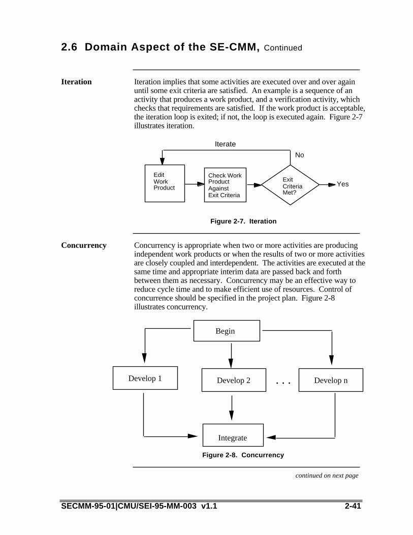
2.6 Domain Aspect of the SE-CMM, Continued
Iteration implies that some activities are executed over and over againuntil some exit criteria are satisfied. An example is a sequence of anactivity that produces a work product, and a verification activity, whichchecks that requirements are satisfied. If the work product is acceptable,the iteration loop is exited; if not, the loop is executed again. Figure 2-7illustrates iteration.
Iteration
YesEdit Work Product
Check Work Product AgainstExit Criteria
Exit Criteria Met?
Iterate
No
Figure 2-7. Iteration
Concurrency is appropriate when two or more activities are producingindependent work products or when the results of two or more activitiesare closely coupled and interdependent. The activities are executed at thesame time and appropriate interim data are passed back and forthbetween them as necessary. Concurrency may be an effective way toreduce cycle time and to make efficient use of resources. Control ofconcurrence should be specified in the project plan. Figure 2-8illustrates concurrency.
Concurrency
Begin
Develop 1 Develop 2 . . . Develop n
Integrate
Figure 2-8. Concurrency
continued on next page
SECMM-95-01|CMU/SEI-95-MM-003 v1.1 2-41

2.6 Domain Aspect of the SE-CMM, Continued
Recursion is the invocation of an activity by the same activity in a newcontext to accomplish a task subordinate to the invoking task. It isuseful in applying system engineering activities to subsystems resultingfrom decomposition of requirements. This form of recursion maycontinue to lower levels. Figure 2-9 illustrates recursion.
Recursion
Activity W___ ________ ________ ________ _____
Activity X___ ________ _____
Do Activity X___ _________ _________ ______
Activity Y__ _______ _______ _____
Figure 2-9. Recursion
2-42 SECMM-95-01|CMU/SEI-95-MM-003 v1.1
2.7 A Path for Improving Systems Engineering Maturity
The following discussion addresses a possible path an organizationmight take in improving its systems engineering processes. Thisprovides a context for describing some of the implied relationshipsbetween the capability levels and process areas that exist in the SE-CMM.
The assumption in the following discussion is that an organization'sprimary goal of an improvement effort is to maximize the utility of thesystems engineering function. These functions may be perceived asbeing the direct "value-added" processes.
There may be temptations in some organizations to focus solely onimproving their engineering processes. The drawback with such anapproach is that it fails to consider the interaction between engineering,project, and organization process areas. For example, a matureengineering process requires a organization that provides a supportingstructure to operate in. Correspondingly, the project maturity must besuch that it fosters a cohesive working environment.
An organization using the SE-CMM for process improvement, can usethe following building block approach.
An examplepath throughthe SE-CMM
continued on next page
SECMM-95-01|CMU/SEI-95-MM-003 v1.1 2-43

2.7 A Path for Improving Systems EngineeringMaturity, Continued
Figure 2-10 illustrates a summarized capability level profile for anorganization, each of whose engineering processes are operating atcapability level 1, the Performed Informally level.
PerformedInformallyEngineering
5
4
3
2
1
0
EngineeringProject Organization
Figure 2-10. Capability Profile for Level 1 Engineering
The engineering processes in an organization can be matured tocapability level 1–Performed Informally–without addressing the projectmanagement or organizational process areas. The benefit of addressingthe engineering process areas is that the first benefits of processimprovement are seen by an organization's systems engineeringcommunity. This helps build motivation for further improvement.
Discussion ofLevel 1
continued on next page
2-44 SECMM-95-01|CMU/SEI-95-MM-003 v1.1

2.7 A Path for Improving Systems EngineeringMaturity, Continued
Figure 2-11 illustrates a summarized capability level profile for anorganization whose engineering processes are operating at capabilitylevel 2, the Planned and Tracked level.
5
4
3
2
1
0
EngineeringProject Organization
Planned andTrackedEngineering
Figure 2-11. Capability Profile for Level 2 Engineering
It is most effective to mature the engineering processes in anorganization to capability level 2–Planned and Tracked–after the projectprocess areas have been brought to Level 1. The project process areasaddress the necessary support for good systems engineering that mustbe done, and that can be done effectively at the project-level to takeadvantage of commonalities in planning and control. The benefits ofprocess improvement are seen at the project-level by systems engineersand those with whom they regularly interface.
Discussion ofLevel 2
continued on next page
SECMM-95-01|CMU/SEI-95-MM-003 v1.1 2-45

2.7 A Path for Improving Systems EngineeringMaturity, Continued
Figure 2-12 illustrates a summarized capability level profile for anorganization whose engineering processes are operating at capabilitylevel 3, the Well Defined level.
5
4
3
2
1
0
EngineeringProject Organization
Well DefinedEngineering
Figure 2-12. Capability Profile for Level 3 Engineering
Bringing the engineering processes in an organization up to capabilitylevel 3–Well Defined, can most effectively be done after the projectprocess areas have been brought to Level 2 and after the organizationalprocess areas have been brought to Level 1. Planning and tracking theproject process areas at the project level provides the quality,configuration, risk, and planning control necessary to provide data toorganizational process improvement activities. Performing theorganizational process areas provides the necessary resources for use bythe engineering process areas at Level 3. Such resources includeorganization's standard systems engineering process, the systemsengineering support environment, and obtaining systems engineeringskills and knowledge.
Discussion ofLevel 3
continued on next page
2-46 SECMM-95-01|CMU/SEI-95-MM-003 v1.1

2.7 A Path for Improving Systems EngineeringMaturity, Continued
Figure 2-13 illustrates a summarized capability level profile for anorganization whose engineering processes are operating at capabilitylevel 4, the Quantitatively Controlled level.
5
4
3
2
1
0
EngineeringProject Organization
Quantita-tivelyControlledEngineering
Figure 2-13. Capability Profile for Level 4 Engineering
Bringing the engineering processes in an organization up to capabilitylevel 4–Quantitatively Controlled, can most effectively be done after theproject and organizational process areas have been brought to Level 3.Having well-defined engineering, project and organizational processareas provides the data (from Generic Practices 3.2.2 and 3.2.3) and thenecessary supporting structures on which improvements in theengineering process areas can be based. At Level 4, an organization willbe able to determine the process capability of its engineering processes.Knowing the capability of a process is the foundation of statisticalprocess control.
Discussion ofLevel 4
continued on next page
SECMM-95-01|CMU/SEI-95-MM-003 v1.1 2-47

2.7 A Path for Improving Systems EngineeringMaturity, Continued
Figure 2-14 illustrates a summarized capability level profile for anorganization whose engineering processes are operating at capabilitylevel 5, the Continuously Improving level.
5
4
3
2
1
0
EngineeringProject Organization
ContinuouslyImprovingEngineering
Figure 2-14. Capability Profile for Level 5 Engineering
Bringing the engineering processes in an organization up to capabilitylevel 5–Continuously Improving, can most effectively be done after theengineering, project and organizational process areas have been broughtto Level 4. Having quantitatively controlled processes provides the datanecessary to execute continuous improvement based on processcapability data.
Discussion ofLevel 5
2-48 SECMM-95-01|CMU/SEI-95-MM-003 v1.1

SECMM-95-01|CMU/SEI-95-MM-003 v1.1 2-49

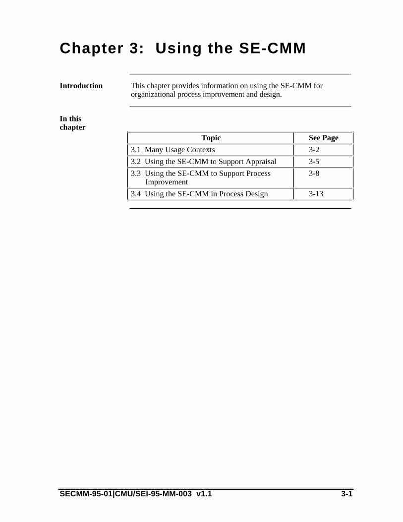
Chapter 3: Using the SE-CMM
This chapter provides information on using the SE-CMM fororganizational process improvement and design.
Introduction
In thischapter
Topic See Page
3.1 Many Usage Contexts 3-2
3.2 Using the SE-CMM to Support Appraisal 3-5
3.3 Using the SE-CMM to Support ProcessImprovement
3-8
3.4 Using the SE-CMM in Process Design 3-13
SECMM-95-01|CMU/SEI-95-MM-003 v1.1 3-1

3.1 Many Usage Contexts
Practitioners in systems engineering recognize that there are as manyproduct contexts as there are products in the marketplace, and themethods used to develop products are as varied as the productsthemselves. However, there are some issues related to product andproject context that are known to have an impact on the way productsare conceived, produced, delivered, and maintained. Two issues inparticular have significance for the SE-CMM
Product/projectcontext
• type of customer base (negotiated vs. market driven)• production cycle (small run, high value vs. large run, lower value)
The differences between two diverse customer bases and the impacts ofthose differences in the SE-CMM are discussed below. This isprovided as an example of how an organization or industry segmentmight go about analyzing of how to use the SE-CMM appropriately intheir environment.
Every industry reflects its own particular culture, nomenclature, andcommunication style. By minimizing the role dependencies andorganization structure implications, the authors hope that practitionersfrom all industry segments will be able to easily translate the conceptsexpressed in the SE-CMM into their own language and culture.However, because of the makeup of the author team, it is natural that thelanguage used to convey SE-CMM concepts has some flavor of theaerospace contractor industry, in which many of the authors have spentsignificant portions of their careers. Users are urged to look beyondspecific terminology differences to the common concepts underneaththe terminology. Users are also encouraged to communicate problemsusing the SE-CMM to the project, via the issue form attached to thisdocument.
SE-CMM notlimited to aparticularindustrysegment
continued on next page
3-2 SECMM-95-01|CMU/SEI-95-MM-003 v1.1

3.1 Many Usage Contexts, Continued
The SE-CMM can be applied in both single-customer and multi-customer segments. The table below illustrates some differences thatare evident in single vs. multi-customer segments that relate to theSE-CMM. Because of these differences, SE-CMM users may find ituseful to tailor the terminology in the model to reflect their customersegment.
Type ofcustomerbase
Aspect
CharacteristicsSeen with Single
Customer
Characteristics Seenwith Multiple
Customers SE-CMMImplications
Number ofcustomers
One entity, eitherone individual orone organization
Many entities, eithermany individuals whocan be segmentedaccording to specificcharacteristics, ormany organizations
Language relatedto customer,customersurrogates shouldbe emphasized
Visibility ofthecustomer
Customer is highlyvisible to thedeveloper
Customer is not oftendirectly visible to thedeveloper:surrogates, such asfocus groups ormarketingdepartments, providethe interface to thedeveloper
UnderstandCustomer Needsprocess area (PA)must beinterpreted to suitthe context
Methods ofmeasuringcustomersatisfaction
• Award of followon work
• Periodicreviews
• Award fee
• Incentive fee
• Customerfeedback
• Marketplacebuying patterns
• Creation of follow-on customerdemands
• Customer survey
Manage ProductLine Evolution PAand otherorganizationalPAs may beaffected by howsupport functionsare viewed inrelation tocustomer-focusedactivities
Table 3-1. Customer Base
continued on next page
SECMM-95-01|CMU/SEI-95-MM-003 v1.1 3-3

3.1 Many Usage Contexts, Continued
The concepts of Six Sigma were pioneered by the Motorola Company.They are quality improvement concepts that have growing acceptance inU.S. industry. Elements of the SE-CMM correspond to the Six Sigmaconcepts. For example, step two and three correspond to theUnderstand Customer Needs and Expectations process area (PA06).The literature expresses the "Six Steps to Six Sigma" for bothmanufacturing and intellectual work. The steps for intellectual work arerepeated here [Morgello 91].
The mapping of the Six Steps to Six Sigma to several parts of the SE-CMM, is shown in Table 3-2.
Relationshipto the "SixSteps to SixSigma"
Six Steps to SixSigma
SE-CMM
Identify yourproducts/services
PA 15: Manage Product Line Evolution
Identify yourcustomers
PA 6: Understand Customer Needs andExpectations
Identify needs PA 6: Understand Customer Needs andExpectations
Define the process PA 13: Define Organization's SystemsEngineering Process
PA 14: Improve Organization's SystemsEngineering Processes
Mistake-proof theprocess andeliminate wastedeffort
PA 14: Improve Organization's SystemsEngineering Processes
GP 2.4.1: Track with measurementGP 3.2.3: Use well-defined dataGP 4.2.1: Determine process capabilityGP 4.2.2: Use process capabilityGP 5.2.3: Continuously improve the defined
processEnsure continuouseffort
GP 5.1.2: Continuously improve thestandard process
GP 5.2.3: Continuously improve the definedprocess
Table 3-2. Six Steps to Six Sigma
3-4 SECMM-95-01|CMU/SEI-95-MM-003 v1.1

3.2 Using the SE-CMM to Support Appraisal
The SE-CMM is structured to support a wide variety of improvementactivities, including self-administered appraisals or internal appraisalsaugmented by expert "facilitators" from inside or outside theorganization. Although it is primarily intended for internal processimprovement, it can also be used to evaluate a potential vendor'scapability to perform its systems engineering process. (This use is notrecommended by the SE-CMM Project at this time.)
Introduction
Although it is not required that any particular appraisal method be usedwith the SE-CMM, an appraisal method designed to maximize theutility of the model has been designed by the SE-CMM Project. TheSE-CMM Appraisal Method (SAM) is fully described, along withsome support materials for conducting appraisals, in SECMM-94-06|CMU/SEI-94-HB-05, SE-CMM Appraisal Method Description.The basic premises of the appraisal method are listed here to providecontext for how the model might be used in an appraisal.
The SE-CMMAppraisalMethod
SAM is an organizational or project-level appraisal method that usesmultiple data-gathering methods to obtain information on the processesbeing practiced within the organization or project selected for appraisal.The purposes of a SAM-style appraisal in its first release version aretwofold:
Features ofthe SAM
• Obtain a baseline or benchmark of actual practice related to systemsengineering within the organization or project.
• Create and support momentum for improvement within multiplelevels of the organizational structure.
SAM is a method which is tailorable to meet the organization's orproject's need, and some guidance on tailoring is provided in the SAMdescription document.
Data gathering is primarily via questionnaires that directly reflect thecontents of the model, and a series of both structured and unstructuredinterviews with key personnel involved in the performance of theorganization's processes. Some of these individuals would beconsidered systems engineers, while others would be in other roles(e.g., configuration managers) that support systems engineering tasks.
Multiple feedback sessions are conducted with the appraisal participants,culminating in a briefing to all participants plus the sponsor of theappraisal. Capability levels are assigned to each of the process areas thatwere appraised. The briefing also includes a set of prioritized strengthsand weaknesses that support process improvement based on theorganization's stated appraisal goals.
SECMM-95-01|CMU/SEI-95-MM-003 v1.1 3-5

continued on next page
3-6 SECMM-95-01|CMU/SEI-95-MM-003 v1.1
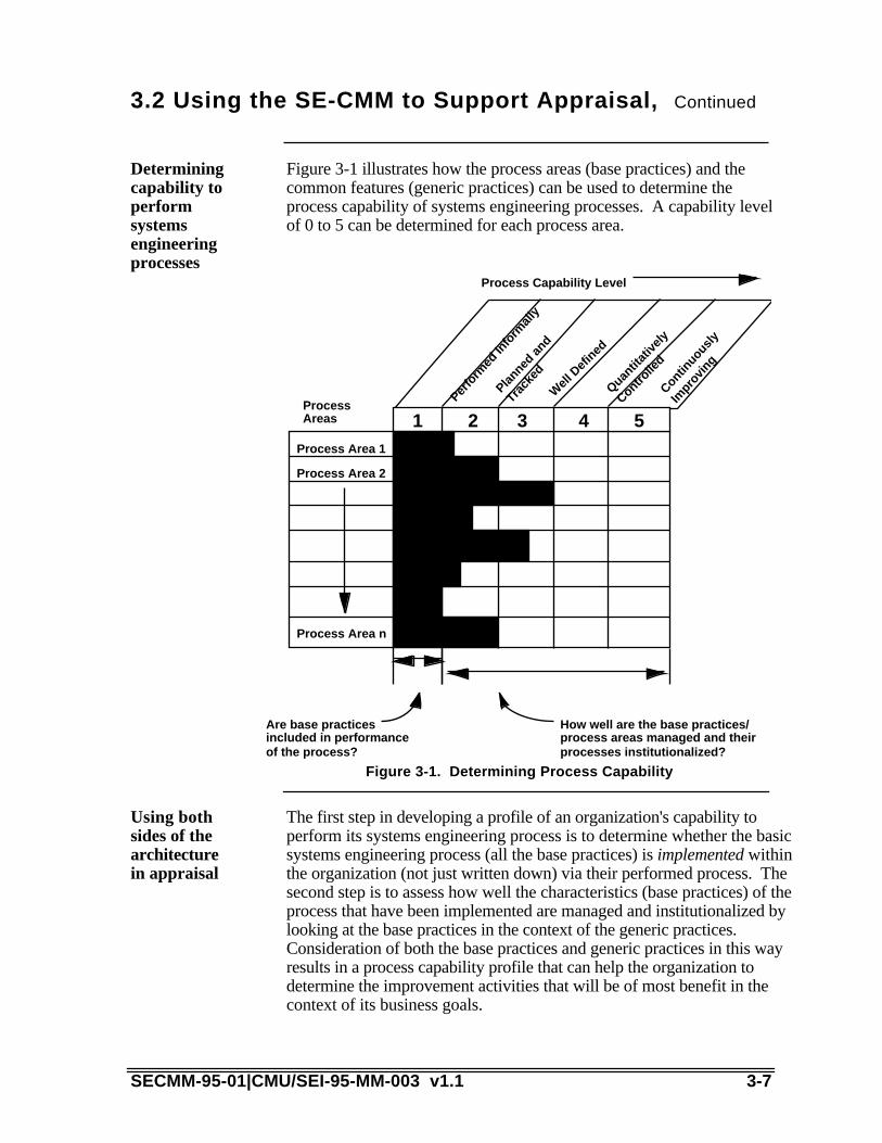
3.2 Using the SE-CMM to Support Appraisal, Continued
Figure 3-1 illustrates how the process areas (base practices) and thecommon features (generic practices) can be used to determine theprocess capability of systems engineering processes. A capability levelof 0 to 5 can be determined for each process area.
Determiningcapability toperformsystemsengineeringprocesses
Process Area 1
Process Area 2
1 2 3 4
Process Capability Level
Process Area n
Process Areas
Are base practicesincluded in performanceof the process?
How well are the base practices/process areas managed and theirprocesses institutionalized?
5
Planned
and
Track
ed
Well
Def
ined
Quantit
ative
ly
Controlle
d
Contin
uous
ly
Impr
ovin
g
Perfo
rmed
Info
rmal
ly
Figure 3-1. Determining Process Capability
The first step in developing a profile of an organization's capability toperform its systems engineering process is to determine whether the basicsystems engineering process (all the base practices) is implemented withinthe organization (not just written down) via their performed process. Thesecond step is to assess how well the characteristics (base practices) of theprocess that have been implemented are managed and institutionalized bylooking at the base practices in the context of the generic practices.Consideration of both the base practices and generic practices in this wayresults in a process capability profile that can help the organization todetermine the improvement activities that will be of most benefit in thecontext of its business goals.
Using bothsides of thearchitecturein appraisal
SECMM-95-01|CMU/SEI-95-MM-003 v1.1 3-7

continued on next page
3-8 SECMM-95-01|CMU/SEI-95-MM-003 v1.1

3.2 Using the SE-CMM to Support Appraisal,Continued
Because process capability levels are primarily determined by applyingthe generic practices to the base practices, the SE-CMM may appear tocontain a certain amount of redundancy between the generic practicesand base practices. This is most visible when looking at some of theproject and organizational process areas. Chapter 4A addresses how thegeneric practices are applied during an appraisal.
Relationshipbetweengeneric andbase practices
The SE-CMM contains both base practices and a generic practice thataddress configuration management: the Manage Configurationsprocess area (PA09) and generic practice 2.2.2 (“Place work productsof the process area under version control or configuration management,as appropriate”). However, the focus of Manage Configurations is theprocess being used for managing configurations. The generic practice,however, addresses whether the project's process for configurationmanagement results in action.
In general, the base practices in cases such as this should be viewed asguidance on the basic aspects of the topics that need to be addressed,and the related generic practices deal with deployment of the basepractices to the project. Keep in mind that the application of the genericpractices to each process area results in a unique interpretation of thegeneric practice for the subject process area.
Example ofrelationshipbetweengeneric/basepractices
The practices of many of the process areas would be expected to be seena number of times in the execution of an organization's process for theproduct life cycle. The process areas should be considered a source forpractices whenever there is a need to incorporate the process area'spurpose in a project's or organization's process. In an appraisal, alwayskeep in mind that the SE-CMM does not imply a sequence: sequencingshould be determined based on the organization's or project's selectedlife cycle and other business parameters (see Section 3.4, Using the SE-CMM in Process Design).
Sequencing
SECMM-95-01|CMU/SEI-95-MM-003 v1.1 3-9

3.3 Using the SE-CMM to Support Process Improvement
Either with or without an appraisal to benchmark an organization’ssystems engineering practices, an organization should consider severalaspects of the SE-CMM when using it as the basis to design animprovement program. This section does not provide overall guidance oninitiating and conducting an improvement program. There are manysources within industry for approaches to organizational improvement, andmost should be able to be used with the SE-CMM or adapted for SE-CMM use.
Introduction
It should be emphasized that any process improvement effort, using anyreference model, should be constructed to support the business goals ofthe organization. An organization using the SE-CMM should prioritizethe process areas relative to their business goals and strive forimprovement in the highest priority process areas first.
Prioritizingimprovementbased onbusiness goals
The model defines only those elements that the authors considered to beessential for the practice of good systems engineering. As such themodel is not intended, in general, to be tailored. However, not allprojects may need to use processes that exhibit all the characteristicsassociated with each process area. Under such circumstances, theproject should follow a process to tailor out the activity related to theunnecessary process area from the organization's systems engineeringprocess. Tailoring should, in all cases, be based on the organization'sgoals and customer needs.
Tailoring
continued on next page
3-10 SECMM-95-01|CMU/SEI-95-MM-003 v1.1

3.3 Using the SE-CMM to Support ProcessImprovement, Continued
Empirical data are not readily available on the benefits of processimprovement to systems engineering. However, because systemsengineering has a strong influence on the success of other disciplines,the benefits from improving the systems engineering process areprojected to equal or exceed the benefits of process improvement inother disciplines such as software engineering.
In the case of software process improvement, organizations that havedone software process improvement for more than three years havegained substantial benefits [Herbsleb 94]:
• return on investment of 7:1• 37% average gain per year in productivity• 18% increase per year in the proportion of defects found in pre-test• 19% reduction in time to market• 45% reduction in filed error reports per year
This is comparable to published total quality management reports fromother industries. Surveys and case studies on software processimprovement are listed below to support model users who need tounderstand the potential analogies between software and systemsengineering process improvement.
Gainingleverage fromotherexperiences
continued on next page
SECMM-95-01|CMU/SEI-95-MM-003 v1.1 3-11

3.3 Using the SE-CMM to Support ProcessImprovement, Continued
Joe Besselman and Stan Rifkin, “The Effect of Software ProcessImprovement on the Economics of Procurement,” Proceedings of the6th SEPG National Meeting, Dallas, TX, 25-28 April 1994.
C. Billings, J. Clifton, B. Kolkhorst, E. Lee, and W.B. Wingert,“Journey to a Mature Software Process,” IBM Systems Journal, Vol.33, No. 1, 1994, pp. 46-61.
Raymond Dion, “Process Improvement and the Corporate BalanceSheet,” IEEE Software, Vol. 10, No. 4, July 1993, pp. 28-35.
James Herbsleb, Anita Carleton, et al., Benefits of CMM-BasedSoftware Process Improvement: Initial Results (CMU/SEI-94-TR-13). Pittsburgh, PA: Software Engineering Institute, Carnegie MellonUniversity, August 1994.
Watts S. Humphrey, Terry R. Snyder, and Ronald R. Willis, “SoftwareProcess Improvement at Hughes Aircraft,” IEEE Software, Vol. 8, No.4, July 1991, pp. 11-23.
A. Johnson, “Software Process Improvement Experience in theDP/MIS Function,” Proceedings of the 16th International Conferenceon Software Engineering, IEEE Computer Society Press, Sorrento,Italy, 16-21 May 1994, pp. 323-330.
Jed Johnson, “How We Climbed to Maturity Level Two,” ApplicationDevelopment Trends, April 1994, pp. 20-23.
W.H. Lipke and K.L. Butler, “Software Process Improvement: ASuccess Story,” Crosstalk: The Journal of Defense SoftwareEngineering, No. 38, November 1992, pp. 29-31.
R. A. Radice, J. T. Harding, P. E. Munnis, and R. W. Phillips, “AProgramming Process Study,” IBM Systems Journal, vol. 24, no. 2,1985.
H. Wohlwend and S. Rosenbaum, “Software Improvements in anInternational Company,” Proceedings of the 15th InternationalConference on Software Engineering, IEEE Computer Society Press,May 1993.
List ofsoftwareprocessimprovementreferences
continued on next page
3-12 SECMM-95-01|CMU/SEI-95-MM-003 v1.1

3.3 Using the SE-CMM to Support ProcessImprovement, Continued
Although the business goals are the primary driver in interpreting amodel such as the SE-CMM, there is a fundamental order of activitiesand basic principles that drive the logical sequence of typicalimprovement efforts. This order of activities is expressed in thecommon features and generic practices of the capability level side of theSE-CMM architecture. These principles and order of activities aresummarized in Table 3-3.
Walk beforeyou run
Principle How Expressed in SE-CMM
You have to do it before youcan manage it.
Performed Informally level focuses onwhether an organization or projectperforms a process that incorporates thebase practices.
Understand what'shappening on the project(where the products are!)before definingorganization-wideprocesses.
Planned and Tracked level focuses onproject-level definition, planning, andperformance issues.
Use the best of what you'velearned from your projectsto create organization-wideprocesses.
Well Defined level focuses on disciplinedtailoring from defined processes at theorganization level.
You can't measure it untilyou know what "it" is.
Although it is essential to begin collectingand using basic project measures early,i.e., at the Planned and Tracked level,measurement and use of data is notexpected organization wide until the WellDefined and, particularly, theQuantitatively Controlled levels havebeen achieved.
Managing withmeasurement is onlymeaningful when you'remeasuring the right things.
Quantitatively Controlled level focuseson measurements being tied to thebusiness goals of the organization.
A culture of continuousimprovement requires afoundation of soundmanagement practice,defined processes, andmeasurable goals.
Continuously Improving level gainsleverage from all the managementpractice improvements seen in the earlierlevels, then emphasizes the cultural shiftsthat will sustain the gains made.
Table 3-3. Process Improvement Principles in the SE-CMM
SECMM-95-01|CMU/SEI-95-MM-003 v1.1 3-13

continued on next page
3-14 SECMM-95-01|CMU/SEI-95-MM-003 v1.1

3.3 Using the SE-CMM to Support ProcessImprovement, Continued
Based on analogies in the software and other communities, some resultsof process and product improvement can be predicted. These arediscussed below.
Someexpectedresults
The first improvement expected as an organization matures ispredictability. As capability increases, the difference between targetedresults and actual results decreases across projects. For instance, Level1 organizations often miss their originally scheduled delivery dates by awide margin, whereas organizations at a higher capability level shouldbe able to predict the outcome of cost and schedule aspects of a projectwith increased accuracy.
Improvingpredictability
The second improvement expected as an organization matures iscontrol. As process capability increases, incremental results can beused to establish revised targets more accurately. Alternative correctiveactions can be evaluated based on experience with the process and otherprojects' process results in order to select the best application of controlmeasures. As a result, organizations with a higher capability level willbe more effective in controlling performance within an acceptable range.
Improvingcontrol
The third improvement expected as an organization matures iseffectiveness. Targeted results improve as the maturity of theorganization increases. That is, as an organization matures, costsdecrease, development time becomes shorter, and productivity andquality increase. In a Level 1 organization, development time can bequite long because of the amount of rework that must be performed tocorrect mistakes. In contrast, organizations at a higher maturity levelhave increased process effectiveness and have reduced costly rework,allowing overall development time to be shortened.
Improvingeffectiveness
SECMM-95-01|CMU/SEI-95-MM-003 v1.1 3-15

3.4 Using the SE-CMM in Process Design
This section provides brief guidance on issues related to using theSE-CMM to support process design. This section sets a context forhow the SE-CMM could be used in a software engineering designactivity.
Introduction
Organizations often overlook many internal and/or intermediateprocesses or products when first defining their processes. However, itis not necessary to address all of the possibilities when first defining asystems engineering process for an organization. The organizationshould describe with reasonable accuracy its current process as abaseline. It is best to focus on capturing a reasonable baseline processthat be produced in six months to a year, and that can be improved overtime.
An organization must have a stable baseline to determine whether futurechanges constitute improvements. There is no value in looking forimprovements in a process that the organization does not perform. Anorganization may find it useful to include current "delays" and "queues"in the baseline process. During subsequent process improvementefforts, these allow a good starting point for cycle-time reduction.
A systems engineering organization may define its process from thepoint of view of what its systems engineers are responsible for. Thismay include interfaces with the implementing disciplines of softwareengineering, electrical engineering, mechanical engineering, and more.
The first step in designing processes that will meet the business needsof an enterprise is to understand the business, product, andorganizational context that will be present when the process is beingimplemented. Some questions that need to be answered before the SE-CMM can be used for process design include
Analyzingyourorganiza-tional context
• What life cycle will be used as a framework for this process?• How is the organization structured to support projects?• How are support functions handled (e.g., by the project or the
organization)?• What are the management and practitioner roles used in this
organization?• How critical are these processes to organizational success?
Understanding the cultural and business contexts in which the SE-CMM will be used is a key to its successful application in processdesign.
continued on next page
3-16 SECMM-95-01|CMU/SEI-95-MM-003 v1.1

3.4 Using the SE-CMM in Process Design, Continued
Figure 3-2 illustrates the factors that need to be added to the content ofthe SE-CMM process areas and common features to come up with aperformable and sustainable process design. It is the organization'scontext regarding role assignments, organizational structure, systemsengineering work products, and product life cycle that, combined withguidance from SE-CMM generic practices and base practices, producessound organizational processes that have the potential for deliberateimprovement.
Adding roleand structureinformation
Role Assignment
Organization Structure
Specific Work Products
Selected LifeCycle
Guidance by SE-CMMOrganizational Context
Soundorganizationalprocesses with a potential for deliberate improvement
Base Practice
GenericPractice
Figure 3-2. Factors for Successful Process Design
SECMM-95-01|CMU/SEI-95-MM-003 v1.1 3-17


Chapter 4: The SE-CMM Generic &Base Practices
This chapter contains the practices for both the process capability anddomain aspects of the SE-CMM. Section 4A contains the genericpractices (process capability aspect), organized by common feature andcapability level. Section 4B contains the base practices (domain aspect),organized by process area. The process areas are sequencedalphabetically within each process category.
Introduction
SECMM-95-01|CMU/SEI-95-MM-003 v1.1 4-1

Chapter 4A: Generic Practices
This chapter contains the generic practices, which express the processcapability side of the model. These generic practices were adapted froman early version of the Baseline Practices Guide (BPG) SPICE's effort.The generic practices are grouped according to common feature andcapability level.
The six capability levels are the numbered levels that apply to eachprocess area. The common features are groups of generic practiceswithin a capability level. They were useful in developing the genericpractices, and can be useful in understanding the progression of genericpractices.
Introduction
The BPG uses the term "process" where the SE-CMM uses "processarea." This change of terminology has been useful to users, whotypically need to create or improve a process for their ownorganizations.
“Process” vs.“processarea”
This chapter is reproduced with minor adaptations for the SE-CMMfrom the SPICE Baseline Practices Guide v1.00a, with the permissionof the Baseline Practices Guide technical center manager. The BPGversion used was a work in progress.
Source
The "Notes" sections of the BPG generic practices were updated toreflect SE-CMM cross-references. In addition, cross-references amonggeneric practices and between generic practices and process areas wereadded.
Adaptationstothe BPG
Chapter 4A is divided into the six process capability levels shownbelow:
In thischapter
Topic See PageThe Not Performed level 4-3The Performed Informally level 4-4The Planned and Tracked level 4-5The Well Defined level 4-9The Quantitatively Controlled level 4-12The Continuously Improving level 4-13
4-2 SECMM-95-01|CMU/SEI-95-MM-003 v1.1
Capability Level 0 - Not Performed
The Not Performed level has no common features. There is generalfailure to perform the base practices in the process area. Where thereare work products that result from performing the process, they are noteasily identifiable or accessible.
Description
SECMM-95-01|CMU/SEI-95-MM-003 v1.1 4-3

Capability Level 1 - Performed Informally
Base practices of the process area are generally performed. However,the performance of these base practices may not be rigorously plannedand tracked. Performance depends on individual knowledge and effort.Individuals within the organization recognize that an action should beperformed, and there is general agreement that this action is performedas and when required. There are identifiable work products for theprocess, which demonstrate the performance of the base practices.
Description
1.1.1 Perform the process. Perform a process that implements thebase practices of the process area to provide work products and/orservices to a customer.
Note: This process may be termed an “informal process.” Thecustomer(s) of the process area may be internal or external to theorganization.
CommonFeature 1.1:BasePractices arePerformed
4-4 SECMM-95-01|CMU/SEI-95-MM-003 v1.1
Capability Level 2 - Planned and Tracked
Base practices of the process area are planned and tracked. Performanceaccording to specified procedures is verified. Work products conformto specified standards and requirements. The organization usesmeasurement to track process area performance, thus enabling theorganization to manage its activities based on actual performance. Theprimary distinction from the Performed Informally level is that theperformance of the process is planned and tracked.
Description
2.1.1 Allocate resources. Allocate adequate resources (includingpeople) for performing the process area.
Relationship to process areas: Identification of critical resources isdone in PA 12 - Plan Technical Effort.
CommonFeature 2.1:PlanningPerformance
2.1.2 Assign responsibilities. Assign responsibilities for developingthe work products and/or providing the services of the process area.
Relationship to process areas: Assignment of responsibilities is relatedto PA 12 - Plan Technical Effort.
continued on next page
SECMM-95-01|CMU/SEI-95-MM-003 v1.1 4-5

Capability Level 2 - Planned and Tracked, Continued
2.1.3 Document the process. Document the approach to performingthe process area in standards and/or procedures.
Note: Participation of the people who perform a process (its owners) isessential to creating a usable process description. Processes in anorganization or on a project need not correspond one-to-one with theprocess areas in the SE-CMM. Therefore, a project's processaddressing a process area may be described in more than one way (e.g.,policies, standards, and/or procedures). Similarly a project's processdescription may span more than one process area.
Relationship to other generic practices: Process descriptions evolvewith increasing process capability. This is the “Level 2” processdescription. See 3.1.1, 3.1.2, 5.2.3 for descriptions of this practice athigher capability levels.
Relationship to process areas: This practice is related to PA 13 -Define Organization’s Systems Engineering Process and PA 14 -Improve Organization’s Systems Engineering Processes.
2.1.4 Provide tools. Provide appropriate tools to support performanceof the process area.
Relationship to other generic practices: Tool changes may be part ofprocess improvements (see 5.2.3 for practices on processimprovements).
Relationship to process areas: Tools are managed in PA 16 - ManageSystems Engineering Support Environment.
CommonFeature 2.1:PlanningPerformance,continued
2.1.5 Ensure training. Ensure that the individuals performing theprocess area are appropriately trained in how to perform the process.
Note: Training, and how it is delivered, will change with processcapability due to changes in how the process(es) is performed andmanaged.
Relationship to process areas: Training and training management isaddressed in PA 17 - Provide Ongoing Skills and Knowledge.
continued on next page
4-6 SECMM-95-01|CMU/SEI-95-MM-003 v1.1

Capability Level 2 - Planned and Tracked, Continued
2.1.6 Plan the process. Plan the performance of the process area.
Note: Plans for process areas in the engineering and project categoriesmay be in the form of a project plan, whereas plans for the organizationcategory may be at the organizational level.
Relationship to process areas: Project planning is described in PA 12 -Plan Technical Effort.
CommonFeature 2.1:PlanningPerformance,continued
2.2.1 Use plans, standards, and procedures. Use documented plans,standards, and/or procedures in implementing the process area.
Note: A process performed according to its process descriptions istermed a “described process.” Process measures should be defined inthe standards, procedures, and plans.
Relationship to other generic practices: The standards and proceduresused were documented in 2.1.3, and the plans used were documented in2.1.6. This practice is an evolution of 1.1.1 and evolves to 3.2.1.
CommonFeature 2.2:DisciplinedPerformance
Relationship to process areas: Using plans implies applying them inpractice as addressed in PA11 - Monitor and Control Technical Effort.
2.2.2 Do configuration management. Place work products of theprocess area under version control or configuration management, asappropriate.
Note: Where PA 09 - Manage Configurations focuses on the generalpractices of configuration management, this generic practice is focusedon the use of these practices to produce the work products of theindividual process area under consideration.
Relationship to process areas: The typical practices needed to supportsystems engineering in the configuration management discipline aredescribed in PA 09 - Manage Configurations.
continued on next page
SECMM-95-01|CMU/SEI-95-MM-003 v1.1 4-7

Capability Level 2 - Planned and Tracked, Continued
2.3.1 Verify process compliance. Verify compliance of the processwith applicable standards and/or procedures.
Relationship to other generic practices: The applicable standards andprocedures were documented in 2.1.3 and used in 2.2.1.
Relationship to process areas: The quality management and/orassurance process is described in PA 08 - Ensure Quality.
2.3.2 Audit work products. Verify compliance of work products withthe applicable standards and/or requirements.
Relationship to other generic practices: The applicable standards andprocedures were documented in 2.1.3 and used in 2.2.1.
Relationship to process areas: Product requirements are developed andmanaged in PA 02 - Derive and Allocate Requirements. Verificationand validation is further addressed in PA 07 - Verify and ValidateSystem.
CommonFeature 2.3:VerifyingPerformance
4-8 SECMM-95-01|CMU/SEI-95-MM-003 v1.1

CommonFeature 2.4:TrackingPerformance
2.4.1 Track with measurement. Track the status of the process areaagainst the plan using measurement.
Note: Building a history of measures, such as cost and schedulevariances, is a foundation for managing by data, and is begun here.
Relationship to other generic practices: The use of measurementimplies that the measures have been defined and selected in 2.1.3 and2.1.6, and data have been collected in 2.2.1. This practice evolves to3.2.3 and 4.2.1.
Relationship to process areas: Project tracking is described in PA 11 -Monitor and Control Technical Effort.
2.4.2 Take Corrective Action. Take corrective action as appropriatewhen progress varies significantly from that planned.
Note: Progress may vary because estimates were inaccurate,performance was affected by external factors, or the requirements, onwhich the plan was based, have changed. Corrective action may involvechanging the process(es), changing the plan, or both.
Relationship to other generic practices: This practice evolves to 4.2.2.
Relationship to process areas: Project control is described in PA 11 -Monitor and Control Technical Effort.
SECMM-95-01|CMU/SEI-95-MM-003 v1.1 4-9
Capability Level 3 - Well Defined
Base practices are performed according to a well-defined process usingapproved, tailored versions of standard, documented processes. Theprimary distinction from the Planned and Tracked level is that theprocess is planned and managed using an organization-wide standardprocess.
Description
3.1.1 Standardize the process. Document a standard process orfamily of processes for the organization, that describes how toimplement the base practices of the process area.
Note: The critical distinction between generic practices 2.1.3 and 3.1.1,the Level 2 and Level 3 process descriptions, is the scope of applicationof the policies, standards, and procedures. In 2.1.3, the standards andprocedures may be in use in only a specific instance of the process, e.g.,on a particular project. In 3.1.1, however, policies, standards, andprocedures are being established at an organizational level for commonuse throughout the organization, and are termed the “standard process.”
The processes in an organization need not correspond one-to-one withthe process areas in this capability maturity model. An organizationmay create more than one standard process description to address aprocess area. Similarly, an organization's process may span multipleprocess areas. The SE-CMM does not dictate the organization orstructure of an organization's process descriptions. Therefore, theorganization may define more than one standard process to addressdifferences among application domains, customer constraints, etc.These related standard processes are termed a “standard processfamily.” The members of a standard process family are typicallysimilar in their descriptions of how and in what order tasks are done.They typically differ in customer constraints, application domain(technology), etc.
Relationship to other generic practices: The Level 2 processdescription was documented in 2.1.3. The Level 3 process descriptionis tailored in 3.1.2.
Relationship to process areas: The process for developing a processdescription is described in PA 13 - Define Organization’s SystemsEngineering Process.
CommonFeature 3.1:Defining aStandardProcess
continued on next page
4-10 SECMM-95-01|CMU/SEI-95-MM-003 v1.1

Capability Level 3 - Well Defined, Continued
3.1.2 Tailor the standard process. Tailor the organization's standardprocess family to create a well-defined process that addresses theparticular needs of a specific use.
Note: Tailoring the organization’s standard process for use by a projector group within the organization creates a project's defined process. Thetailoring addresses the particular needs of the project.
Relationship to other generic practices: The organization's standardprocess (family) is documented in 3.1.1. The tailored process definitionis used in 3.2.1.
Relationship to process areas: Tailoring guidelines are defined in PA13 - Define Organization’s Systems Engineering Process.
CommonFeature 3.1,Defining aStandardProcess,continued
continued on next page
SECMM-95-01|CMU/SEI-95-MM-003 v1.1 4-11

Capability Level 3 - Well Defined, Continued
3.2.1 Use a well-defined process. Use a well-defined process inimplementing the process area.
Note: A well-defined process is characterized by readiness criteria,inputs, standards and procedures, verification mechanisms (such asdefect reviews), outputs, and completion criteria. An organization'sstandard process (or processes) should be well defined. When theorganization's standard process is well defined, a project may create awell-defined process for its use by tailoring the organization's well-defined process to meet project needs.
Relationship to other generic practices: This practice evolved from 2-2-1 and is related to the well-defined process created in 3.1.2.
3.2.2 Perform defect reviews. Perform defect reviews of appropriatework products of the process area.
Note: In SPICE's BPG and the CMM for Software, defect reviews arecalled peer reviews. The purpose of defect reviews is to use aninspection technique to identify sources of error in early or interimsystems engineering work products. The inspection techniquesdescribed in the software literature are readily adaptable to otherdevelopment aspects, such as systems engineering.
3.2.3 Use well-defined data. Use data from performing the definedprocess to manage it.
Note: An example would be classification of defects by the programphase (e.g., requirement, design) in which they were introduced,detected, and corrected.
In a well-defined process, measurements are tailored from thosedescribed by the organization's standard process. Other measures maybe added, for example, as pilots for improvements. Data collection,analysis, and reporting are planned, and benefit both control andimprovement activities. Data are used, as in 2.4.1 and 2.4.2, to trackand initiate corrective action when deviations from planned performanceare significant. Data are also used as a basis for identifying andprioritizing improvement opportunities. In addition, data should becollected on experiments or pilots of new or improved processelements, so as to understand their success or failure.
Relationship to other generic practices: This is an evolution of 2.4.1and 2.4.2; corrective action taken here is based on a well-definedprocess, which has objective criteria for determining progress (see3.2.1). In addition, all of Level 4 builds on this practice.
CommonFeature 3.2:Perform theDefinedProcess
4-12 SECMM-95-01|CMU/SEI-95-MM-003 v1.1

SECMM-95-01|CMU/SEI-95-MM-003 v1.1 4-13

Capability Level 4 - Quantitatively Controlled
Detailed measures of performance are collected and analyzed. Thisleads to a quantitative understanding of process capability and animproved ability to predict performance. Performance is objectivelymanaged, and the quality of work products is quantitatively known.The primary distinction from the Well Defined level is that the definedprocess is quantitatively understood and controlled.
Description
4.1.1 Establish quality goals. Establish measurable quality goals forthe work products of the organization's standard process family.
Note: These quality goals can be tied to the strategic quality goals of theorganization, the particular needs and priorities of the customer, or thetactical needs of the project. The measurements referred to here gobeyond the traditional end-product measurements. They are intended toimply sufficient understanding of the processes being used to enable theorganization to set and use intermediate goals for work-product quality.
Relationship to other generic practices: Data gathered via defectreviews (3.2.2) can be particularly important in setting goals for work-product quality.
CommonFeature 4.1:EstablishingMeasurableQuality Goals
4.2.1 Determine process capability. Determine the process capabilityof the defined process quantitatively.
Note: This is a quantitative process capability based on a well-defined(3.1.1) and measured process. Measurements are inherent in theprocess definition and are collected as the process is being performed.
Relationship to other generic practices: The defined process isestablished through tailoring in 3.1.2 and is performed in 3.2.1. Dataare collected in 3.2.3 and used here.
CommonFeature 4.2:ObjectivelyManagingPerformance
4-14 SECMM-95-01|CMU/SEI-95-MM-003 v1.1
4.2.2 Use process capability. Take corrective action as appropriatewhen the process is not performing within its process capability.
Note: Special causes of variation, identified based on an understandingof process capability, are used to understand when and what kind ofcorrective action is appropriate.
Relationship to other generic practices: This practice is an evolution of3.2.3, with the addition of quantitative process capability to the definedprocess.
Relationship to process areas: When an out-of-control condition isdefected, PA11 - Monitor and Control Technical Effort is involved.
SECMM-95-01|CMU/SEI-95-MM-003 v1.1 4-15
Capability Level 5 - Continuously Improving
The organization establishes quantitative performance goals (targets) forprocess effectiveness and efficiency, based on its business goals. Theorganization is able to continuously improve its process by gatheringquantitative data from performing the defined processes and frompiloting innovative ideas and technologies. The primary distinctionfrom the Quantitatively Controlled level is that the defined process andthe standard process undergo continuous refinement and improvement,based on a quantitative understanding of the impact of changes to theseprocesses.
Description
5.1.1 Establish process effectiveness goals. Establish quantitativegoals for improving process effectiveness of the standard processfamily, based on the business goals of the organization and the currentprocess capability.
5.1.2 Continuously improve the standard process. Continuouslyimprove the process by changing the organization's standard processfamily to increase its effectiveness.
Note: The information learned from managing individual projects iscommunicated back to the organization for analysis and deployment toother applicable areas. Changes to the organization's standard processfamily may come from innovations in technology or incrementalimprovements. Innovative improvements will usually be externallydriven by new technologies. Incremental improvements will usually beinternally driven by improvements made in tailoring for the definedprocess. The goal of improving the standard process is to reducecommon causes of variation in the process.
CommonFeature 5.1:ImprovingOrganizationalCapability
Relationship to other generic practices: Special causes of variation arecontrolled in 4.2.2.
Relationship to process areas: Organizational process improvement isdescribed in PA 14 - Improve Organization’s Systems EngineeringProcesses.
continued on next page
4-16 SECMM-95-01|CMU/SEI-95-MM-003 v1.1
Capability Level 5 - Continuously Improving, Continued
5.2.1 Perform causal analysis. Perform causal analysis of defects.
Note: Those who perform the process are typically participants in thisanalysis. This is a proactive causal analysis activity as well as reactive;defects from prior projects of similar attributes can be used to targetimprovement areas for the new effort.
Relationship to other generic practices: Results of these analyses areused in 5.2.2 and 5.2.3.
CommonFeature 5.2:ImprovingProcessEffectiveness
5.2.2 Eliminate defect causes. Eliminate the causes of defects in thedefined process selectively.
Note: Defect causes are selectively eliminated because it may beimpractical to perform causal analysis (5.2.1) on all defects. In thiscase, some screening may be used.
Relationship to other generic practices: Causes were identified in5.2.1.
5.2.3 Continuously improve the defined process. Continuouslyimprove process performance by changing the defined process toincrease its effectiveness.
Note: The improvements may be based on incremental improvements(5.1.2) or innovative improvements such as new technologies (perhapsas part of pilot testing). Improvements will typically be driven by thegoals established in 5.1.1.
Relationship to other generic practices: Practice 5.2.2 may be onesource of improvements. Goals were established in 5.1.1.
Relationship to process areas: Improvements are addressed in PA 15 -Manage Product Line Evolution and PA14 - Improve Organization'sSystems Engineering Processes.
SECMM-95-01|CMU/SEI-95-MM-003 v1.1 4-17

Chapter 4B: Process Areas/BasePractices
This chapter contains the base practices, that is, the practices consideredessential to the conduct of basic systems engineering.
In thischapter
Topic See Page
Process Area (PA) Format 4-16
PA 01: Analyze Candidate Solutions 4-18
PA 02: Derive and Allocate Requirements 4-23
PA 03: Evolve System Architecture 4-34
PA 04: Integrate Disciplines 4-42
PA 05: Integrate System 4-47
PA 06: Understand Customer Needs and Expectations 4-53
PA 07: Verify and Validate System 4-59
PA 08: Ensure Quality 4-66
PA 09: Manage Configurations 4-72
PA 10: Manage Risk 4-77
PA 11: Monitor and Control Technical Effort 4-82
PA 12: Plan Technical Effort 4-86
PA 13: Define Organization's Systems EngineeringProcess
4-95
PA 14: Improve Organization's Systems EngineeringProcesses
4-100
PA 15: Manage Product Line Evolution 4-104
PA 16: Manage Systems Engineering SupportEnvironment
4-108
PA 17: Provide Ongoing Skills and Knowledge 4-113
PA 18: Coordinate with Suppliers 4-120
4-18 SECMM-95-01|CMU/SEI-95-MM-003 v1.1

Process Area Format
At present, the SE-CMM domain aspect consists of 18 process areas(PAs), each of which contains a number of base practices. Eachprocess area is described in the following subsections.
The general format of the process areas is shown in Figure 4-1. Thesummary description contains a brief overview of the purpose of thePA. Each PA is decomposed into a set of base practices (BPs). TheBPs are considered mandatory items, (i.e., they must be successfullyimplemented to accomplish the purpose of the process area theysupport). Each base practice is described in detail following the PAsummary.
Although the PAs are identified and discussed separately, they do notexist in a vacuum. Even the PAs in the engineering category (PA-01through PA-07), are inextricably intertwined with all the others in thecreation of good systems engineering processes, the implementation ofwhich produces sound, customer-pleasing products.
Currentcontents
continued on next page
SECMM-95-01|CMU/SEI-95-MM-003 v1.1 4-19

Process Area Format, Continued
The following figure provides the general format of the process areasand describes the content of each part.
Figure
PA #: PA Title
SummaryDescription
The purpose of <PA Title> is. . .<description of the purpose of the PA and summary of its major points>
Process AreaNotes
<PA notes paragraphs>
Base PracticesList
The following list contains the titles of the base practices that are essential elementsof good systems engineering:
• BP #: BP Title.....
end of PA Summary Section
BP #BP Title
<BP text: imperative, verb-object statement that describes an essential element for attaining the purpose of the PA>
BP Description<BP description text: provides elaborations of the base practice text.>
Typical Work Products<List of work products>
BP Notes<BP notes text: contains conceptual examples, potential techniques, methods, etc.; content of these will vary from base practice to base practice.>
end of Process Area <PA Title>
Figure 4-1. Process Area Format
4-20 SECMM-95-01|CMU/SEI-95-MM-003 v1.1

PA 01: Analyze Candidate Solutions
The purpose of Analyze Candidate Solutions is to perform studies andanalyses that will result in the selection of a solution to meet theidentified problem and its defined constraints. Analyze CandidateSolutions involves defining the approach and evaluation criteria for theanalysis, as well as for choosing, selecting, and studying the candidatesolutions. It also involves communicating the rationale and results ofthe analysis.
Summarydescription
Analyze Candidate Solutions may be invoked from any of the otherprocess areas. This process area (PA) identifies the characteristics of aprocess for choosing a solution from several alternatives.
Candidate solutions may be provided by the invoking PA, but additionalsolutions may be generated in this PA when needed to further theanalysis.
Analyze Candidate Solutions should be invoked throughout the life of aproject. It may be used for the following types of decisions, amongothers
Process areanotes
• design decision• production decisions• life-cycle cost decisions• human factors decisions• risk reduction decisions
The following list contains base practices that are essential elements ofgood systems engineering: BP.01.01 Establish evaluation criteria based on the identified problem and its
defined constraints.BP.01.02 Define the general approach for the analysis, based on the
established evaluation criteria.BP.01.03 Identify alternatives for evaluation in addition to those provided with
the problem statement.BP.01.04 Analyze the competing candidate solutions against the established
evaluation criteria.BP.01.05 Select the solution that satisfies the established evaluation criteria.BP.01.06 Capture the disposition of each alternative under consideration and
the rationale for the disposition.
Base practiceslist
continued on next page
SECMM-95-01|CMU/SEI-95-MM-003 v1.1 4-21

PA 01: Analyze Candidate Solutions, Continued
Establish evaluation criteria based on the identified problem andits defined constraints.
DescriptionThe criteria used in the evaluation process may vary considerably,depending on the stated problem and the level and complexity of theanalysis. The criteria are weighted or ranked in order of importance.For more complex analyses, there may be levels of criteria.
Typical Work Products
BP 01.01EstablishEvaluationCriteria
• captured evaluation criteria• trade-study criteria• defect data-related criteria
NotesAt the system level, parameters of primary importance include systemperformance, cost effectiveness, producibility, logistics, risk, andoperational availability and maintainability.
Define the general approach for the analysis, based on theestablished evaluation criteria.
DescriptionThe general approach, resources, and procedures for performing theanalysis should be defined based on the evaluation criteria, personnel,tools, facilities, special equipment, and related resources. The generalapproach for the analysis should be defined and documented to ensurethat the procedures can be consistently repeated.
Typical Work Products• trade-study approach
BP 01.02DefineAnalysisApproach
• problem solving process
NotesSome example approaches that could be used to analyze candidatesolutions are
4-22 SECMM-95-01|CMU/SEI-95-MM-003 v1.1

• prototyping• simulation• modeling• trade study• decision tree• literature search• exploitation of prior analyses• elicitation of expert judgment• process quality improvement team
continued on next page
SECMM-95-01|CMU/SEI-95-MM-003 v1.1 4-23

PA 01: Analyze Candidate Solutions, Continued
Identify alternatives for evaluation in addition to those providedwith the problem statement.
DescriptionCandidate solutions may be furnished with the need for analysis. Asthe analysis proceeds, other alternatives may be added to the list ofcandidate solutions.
Typical Work Products• trade-study alternatives• decision tree
NotesSome requests for analysis may be made without supplying anycandidate solutions; in these cases, the subject matter experts wouldneed to identify all of the alternative candidate solutions.
On the other hand, some requests for analysis may be made that alreadysupply every possible candidate solution. In that case, this practicewould not be applicable.
BP 01.03IdentifyAdditionalAlternatives
Analyze the competing candidate solutions against the establishedevaluation criteria.
DescriptionAnalyses should be defined, conducted, and documented at the variouslevels of functional or physical detail to support the decision needs ofthe systems engineering process. The level of detail of a study shouldbe commensurate with cost, schedule, performance, and risk impacts.
Typical Work Products• analyses of candidate solutions
NotesAn example activity: Perform a sensitivity analysis on candidatesolutions to determine if small variations in parameters will affect theoutcome.
BP 01.04AnalyzeCandidateSolutions
continued on next page
4-24 SECMM-95-01|CMU/SEI-95-MM-003 v1.1

PA 01: Analyze Candidate Solutions, Continued
Select the solution that satisfies the established evaluation criteria.
DescriptionZero, one, or several solutions may be found that satisfy the evaluationcriteria. The objective is to arrive at a decision where the selectedapproach is preferred among the alternatives, based on the evaluationcriteria.
Typical Work Products• trade study• rationale for preferred solution• description of the preferred solution
NotesThe following questions will usually arise when selecting amongalternative solutions:• How much better is the selected approach than the next best
alternative?• Is there a significant difference between the results of the comparative
evaluation?• Have all feasible alternatives been considered?• What are the areas of risk and uncertainty?
BP 01.05SelectSolution
continued on next page
SECMM-95-01|CMU/SEI-95-MM-003 v1.1 4-25

PA 01: Analyze Candidate Solutions, Continued
Capture the disposition of each alternative under considerationand the rationale for the disposition.
DescriptionThe results from all system analysis activities should be captured andmaintained in a decision database. The disposition of each alternativeunder consideration and the rationale for the disposition should also bedocumented in the decision database.
Typical Work Products• evaluation of alternatives for the trade study• mathematical models of appropriate solutions• reports of prototype operation• results of tradeoff studies• other supporting data of all studies
NotesExamples of ways to capture results include• formal, deliverable documentation• informal, internal documentation• computer files• a prototyped product• an engineering log book• change request database
BP 01.06CaptureResults
End of PA 01: Analyze Candidate Solutions
4-26 SECMM-95-01|CMU/SEI-95-MM-003 v1.1

PA 02: Derive and Allocate Requirements
The purpose of Derive and Allocate Requirements is to analyze thesystem and other requirements and derive a more detailed and preciseset of requirements. These derived requirements are allocated to systemfunctions', objects', people', and supporting processes, products, andservices, which can be used to synthesize solutions. This process areaaddresses both the analysis of system-level requirements and theallocation of system-level or derived requirements to lower levelfunctions or objects. This involves addressing the concept of operations,functional partitioning, object identification, and performance allocation,as well as capturing the status and traceability of requirements. Thederived and allocated requirements will evolve as the systemsrequirements evolve over time. When corrective actions have an impacton requirements, it may be necessary to revise the derived and allocatedrequirements.
Summarydescription
The practices in the Derive and Allocate Requirements process areaoperate in parallel with the practices in the Evolve System Architectureprocess area (PA 03). Potential derived requirements are evaluated forfeasibility against the functional partitions or objects, and are evaluatediteratively against the components of the architecture. It is important tonote that the terms "function" and "functional" do not preclude object-oriented methods. Objects perform functions, and functions may beperformed by objects. When conflicts or issues are identified withcustomer or derived requirements (e.g., requirements are not verifiableper the verification and validation practices), the issues may be referredto the practices of the process areas Understand Customer Needs andExpectations (PA06) or Analyze Candidate Solutions (PA01).
Process areanotes
continued on next page
SECMM-95-01|CMU/SEI-95-MM-003 v1.1 4-27

PA 02: Derive and Allocate Requirements, Continued
The following list contains the base practices that are essential elementsof good systems engineering:
BP.02.01 Develop a detailed operational concept of the interaction of thesystem, the user, and the environment, that satisfies the operationalneed.
BP.02.02 Identify key requirements that have a strong influence on cost,schedule, functionality, risk, or performance.
BP.02.03 Partition requirements into groups based on established criteria (suchas similar functionality, performance, or coupling) to facilitate andfocus the requirements analysis.
BP.02.04 Derive, from the system and other (e.g., environmental)requirements, requirements that may be logically inferred andimplied as essential to system effectiveness.
BP.02.05 Identify the requirements associated with external interfaces to thesystem and interfaces between functional partitions or objects.
BP.02.06 Allocate requirements to functional partitions, objects, people, orsupport elements to support synthesis of solutions.
BP.02.07 Analyze requirements to ensure that they are verifiable by themethods available to the development effort.
BP.02.08 Maintain requirements traceability to ensure that lower level(derived) requirements are necessary and sufficient to meet theobjectives of higher level requirements.
BP.02.09 Capture system and other requirements, derived requirements,derivation rationale, allocations, traceability, and requirementsstatus.
Base practiceslist
continued on next page
4-28 SECMM-95-01|CMU/SEI-95-MM-003 v1.1
PA 02: Derive and Allocate Requirements, Continued
Develop a detailed operational concept of the interaction of thesystem, the user, and the environment, that satisfies theoperational need.
DescriptionThis practice adds detail to the operational concept used to developsystem requirements. The operational concept includes scenarios andtimelines of the system's responses to stimuli. The behavior of thesystem and its elements is organized by states, modes, and timesequences. The behavior is flowed down to subsystem elements asrequired to fully discover the derived and allocated requirements foreach system element. The operational behavior of the system andsubsystem includes the behavior required to meet the customer’soperational need and any exceptional behavior that may be caused by theenvironment or system faults.
Typical Work Products• operational concept• user interaction sequences• maintenance operational sequences• timelines• simulations• usability analysis
NotesExamples of activities to develop a detailed operational concept include
BP 02.01DevelopDetailedOperationalConcept
• Develop a prototype of the user interface and capture vignettes of userinteraction.
• Develop a system simulation.
Development and analysis of operational concepts are valuable toolsused in the practices of the process areas Understand Customer Needsand Expectations (PA06) and Derive and Allocate Requirements(PA02). They help the analyst to discover new requirements and toverify and validate existing or potential requirements. Operationalconcepts, simulations, and prototypes are key to user-centereddevelopment and maintenance processes.
continued on next page
SECMM-95-01|CMU/SEI-95-MM-003 v1.1 4-29

PA 02: Derive and Allocate Requirements, Continued
Identify key requirements that have a strong influence on cost,schedule, functionality, risk, or performance.
DescriptionIn analyzing system and derived requirements, requirements are oftenidentified that have an especially strong influence on the cost,development schedule, risk, or performance of a product. The total setof requirements is screened for potential key requirements. A cost-benefit analysis is then performed on these requirements using theprocess areas Analyze Candidate Solutions (PA01) and Evolve SystemArchitecture (PA03). The results of analyzing key requirements may bereviewed with the customer using the methods of the UnderstandCustomer Needs and Expectations process area (PA06). Keyrequirements that show a relatively low benefit-to-cost ratio, high risk,or long development schedule are candidates for negotiation with thecustomer. Key requirements are a primary input to the activities of theManage Risk process area (PA10).
Typical Work Products• key requirements issues• benefit-to-cost sensitivity analyses for key requirements
NotesAn example activity: Identify performance requirements that are nearthe limits of what has been achieved before (near the state of the art).
BP 02.02Identify KeyRequirementIssues
continued on next page
4-30 SECMM-95-01|CMU/SEI-95-MM-003 v1.1

PA 02: Derive and Allocate Requirements, Continued
Partition requirements into groups based on established criteria(such as similar functionality, performance, or coupling) tofacilitate and focus the requirements analysis.
DescriptionRequirements are evaluated for similarity in function and grouped intoappropriate partitions. Criteria for appropriate functional partitions areestablished and may include, in addition to similarity, high couplingwithin functional partition and low coupling between functionalpartitions. Functional partitions are chosen so that overall performancerequirements can be budgeted to the functions.
Typical Work Products• identified functional partitions• functional performance budgets
NotesExamples of activities to partition requirements include• Group all requirements that apply to user interaction.• Group all requirements that apply to data storage and retrieval.• Use affinity diagrams.
Functional partitions include functions and subfunctions whoserequirements are ultimately allocated to physical architecture elements.
BP 02.03PartitionFunctions
continued on next page
SECMM-95-01|CMU/SEI-95-MM-003 v1.1 4-31

PA 02: Derive and Allocate Requirements, Continued
Derive, from the system and other (e.g., environmental)requirements, requirements that may be logically inferred andimplied as essential to system effectiveness.
DescriptionDerived requirements are those requirements that are explicitlyidentified or discovered as necessary implications of stated system andother top-level requirements. A system requirement's derivedrequirements "represent" the system requirement in terms ofdevelopment constraints and verification. Typically, a systemrequirement may have to be decomposed into one or more derivedrequirements in order to allocate responsibility and to provide forfeasible verification. Derived requirements apply to all aspects of thedeveloped system, including the development, production,environmental, and operational parameters. Derived requirements mayresult from a single higher level requirement or partitions of higher levelrequirements.
Typical Work Products• derived operational requirements assigned to a functional partition• derived performance requirements
NotesExamples include
BP 02.04DeriveRequirements
• Assess system requirements for derived requirements relating to theoperational environment.
• Produce derived requirements necessary to render systemrequirements testable.
• Produce derived requirements necessary to allocate system timingbudgets to functional partitions.
• Produce rationale for derived requirements.
Derived functional and performance requirements are allocated directly,or as appropriate, to functional partitions, derived requirements, andultimately to physical architecture elements.
continued on next page
4-32 SECMM-95-01|CMU/SEI-95-MM-003 v1.1

PA 02: Derive and Allocate Requirements, Continued
Identify the requirements associated with external interfaces to thesystem and interfaces between functional partitions or objects.
DescriptionExternal and internal interfaces are identified throughout the analysis ofsystem requirements. Identification of these interfaces is essential to thedevelopment of a complete set of requirements for the physicalarchitecture. The early and complete definition of external interfaces isespecially important in characterizing the overall functionality of thesystem because the interfaces are typically independent of the internalarchitecture. Also, external interfaces may be a driver of the internalarchitecture and functionality. This is especially true of the userinterface. The internal interfaces and their related derived requirementsare identified in conjunction with the functional or object partitioning.After partitions are identified, their interfaces and logical data flows aredefined.
Typical Work Products• interface requirements
NotesExamples include
BP 02.05DevelopInterfaceRequirements
• Identify the input and output data for each user interface function.• Identify the input and output data of all external systems that must
interface to the subject system.• Identify the physical requirements of all external system interfaces.• Identify need for physical mounting requirements• Identify operator stimuli and control points.• Identify signal and control structures.• Identify interfaces to the environment.
External stimuli identified in Develop Detailed Operational Concept(BP02.01) are candidates for external interfaces. The identification ofexternal interfaces is facilitated by the development and understandingof the detailed operational concept. In addition, the identification ofexternal interfaces forms the basis for derived external interfacerequirements, as well as many derived functional and performancerequirements. Interfaces are captured and controlled according to thepractices of the Integrate System process area (PA05).
continued on next page
SECMM-95-01|CMU/SEI-95-MM-003 v1.1 4-33

PA 02: Derive and Allocate Requirements, Continued
Allocate requirements to functional partitions, objects, people, orsupport elements to support synthesis of solutions.
DescriptionThe purpose of this practice is to facilitate development of the functionalarchitecture at successively lower partitions. Requirements are initiallyallocated to functional partitions (which may include functions orobjects, and subfunctions) and ultimately to system elements andcomponents. The allocations are performed so that the derivedrequirements can be implemented to satisfy the higher levelrequirements. Where it appears that a requirement is to be satisfiedjointly by several system elements, it is necessary to derive separaterequirements for each system element.
Alternatives should be considered regarding the allocation ofrequirements to people versus systems. Support elements (includingprocesses, production, maintenance, and environmental constraints)should be evaluated for allocation of derived requirements.
Typical Work Products• derived requirements• attributes of allocated requirements
NotesExamples include
BP 02.06AllocateRequirements
• Identify the requirements and derived requirements that apply to allfunctions or objects and allocate these requirements to all elements.
• Identify requirements and derived requirements that constitute aperformance partition and uniquely allocate these requirements to theappropriate function or object.
Allocations of functional and performance requirements facilitate thedivision of responsibilities for development and testing. The practicesof the process areas Understand Customer Needs and Expectations(PA06), Derive and Allocate Requirements (PA02), and EvolveSystem Architecture (PA03) iterate the allocation of requirements.
continued on next page
4-34 SECMM-95-01|CMU/SEI-95-MM-003 v1.1

PA 02: Derive and Allocate Requirements, Continued
Analyze requirements to ensure that they are verifiable by themethods available to the development effort.
DescriptionThe method and feasibility of verifying requirements is established earlyin the development cycle. It is essential for a system or derivedrequirement to have characteristics that can be verified to prove that theresulting product meets the intended purpose. Evaluating the feasibilityof verifying a potential requirement facilitates the production of goodrequirements. Throughout the life cycle, requirements are continuallyassessed to ensure the feasibility of verification, especially in connectionwith evaluating changes to requirements. Methods of verificationinclude inspection, test, demonstration, and analysis.
Typical Work Products• verifiability status of requirements• captured verification method
NotesAn example activity: Assess the feasibility of verifying eachrequirement.
It is important to ensure that requirements verification is performediteratively and recursively with the practices of the Verify and ValidateSystem process area (PA07).
BP 02.07EnsureRequirementVerifiability
continued on next page
SECMM-95-01|CMU/SEI-95-MM-003 v1.1 4-35

PA 02: Derive and Allocate Requirements, Continued
Maintain requirements traceability to ensure that lower level(derived) requirements are necessary and sufficient to meet theobjectives of higher level requirements.
DescriptionThis practice captures, maintains, and controls the traceability and statusof requirements throughout the product life cycle. Of particularimportance is the relationship between higher level requirements andtheir associated derived requirements, which in effect represent thehigher level requirement. This dependence of derived requirements onother requirements or design features is referred to as traceability and isrecorded and maintained from the highest level (most general) to thelowest level (most specific) as the requirements and design evolve. Acontinuous assessment of the lower level requirements and the validityof their traceability is conducted to ensure that the developed system orproduct meets all the requirements, but does not have features beyondwhat is necessary to meet the requirements.
Typical Work Products• requirement exception report• requirement traceability tables• requirements databases• traceability exception report
NotesExamples include
BP 02.08MaintainRequirementSufficiencyandTraceability
• Perform analyses to ensure that related sets of derived requirements,taken as a whole, meet the intent of the parent requirement.
• Perform analyses to ensure that there are no unnecessaryrequirements.
• Verify requirements traceability.
All practices involving creating, changing, or verifying of requirements(especially those of the process areas Understand Customer Needs andExpectations (PA06), Derive and Allocate Requirements (PA02),Evolve System Architecture (PA03), and Verify and Validate System(PA07)) must maintain requirements traceability.
continued on next page
4-36 SECMM-95-01|CMU/SEI-95-MM-003 v1.1

PA 02: Derive and Allocate Requirements, Continued
Capture system and other requirements, derived requirements,derivation rationale, allocations, traceability, and requirementsstatus.
DescriptionThis base practice forms the basis for systematically developing andverifying a system that meets the customer's operational andperformance expectations within acceptable constraints of cost andschedule. Captured results also include other attributes of requirementssuch as a unique requirement number, interpretation, test method,issues, and acceptance/change status.
Typical Work Products• requirement document• requirements databases• interface requirements document• functional architecture• requirement allocation sheet
NotesExamples of activities for capturing results and rationale include
BP 02.09CaptureResults andRationale
• Enter requirements, their traceability, allocation, and status into arequirements database.
• Distribute, review and coordinate requirements data with thedevelopment team.
The collection of work products from this process area is sometimescalled the functional architecture.
The capture of results and rationale applies to all the practices associatedwith the derivation and allocation of requirements as well as the analysisof candidate solutions and design decisions.
End of PA 02: Derive and Allocate Requirements
SECMM-95-01|CMU/SEI-95-MM-003 v1.1 4-37
PA 03: Evolve System Architecture
The purpose of Evolve System Architecture is to provide a basis forestablishing and evolving a system design. It involves deriving thearchitecture requirements, identifying key design issues, determining thefunctional and physical structure and interfaces, and allocating thearchitecture requirements to system elements. The practices describedherein are expected to be performed iteratively with other systemsengineering practices until the architecture is handed off to theimplementing or component engineering disciplines.
System architecture comprises functional (or logical), physical(tangible), and foundation architectures. Evolve System Architectureactivities are applicable to all life-cycle phases of a product and may beinitiated either by new development, changes in requirements, orcorrective actions.
Summarydescription
This process area generates candidate solutions and then makes use ofthe Analyze Candidate Solutions process area (PA01) to choose analternative that meets established criteria for the system architecture.This process area is performed iteratively with the process areasUnderstand Customer Needs and Expectations (PA06) and Derive andAllocate Requirements (PA02).
Process areanotes
The following list contains the base practices that are essential elementsof good systems engineering: BP.03.01 Derive the requirements for the system architecture.BP.03.02 Identify the key design issues that must be resolved to support
successful development of the system.BP.03.03 Generate alternative(s) and constraints for the architecture and select
a solution in accordance with the Analyze Candidate Solutionsprocess area (PA01).
BP.03.04 Develop the interface requirements for the selected architecturecomponents.
BP.03.05 Allocate the system and derived requirements to the chosenarchitecture components and interfaces.
BP.03.06 Maintain requirement traceability for the architecture's requirementsto ensure that lower level (derived) requirements are necessary andsufficient to meet the needs of higher level requirements or design.
BP.03.07 Describe the system architecture by capturing the design results andrationale.
BP.03.08 Identify appropriate derived requirements that address theeffectiveness and cost of life-cycle phases following development,such as production and operation.
Base practiceslist
continued on next page
4-38 SECMM-95-01|CMU/SEI-95-MM-003 v1.1
PA 03: Evolve System Architecture, Continued
Derive the requirements for the system architecture.
DescriptionThis activity makes use of and iterates with a number of other activities,including development and evolution of system requirements,integration, and verification. Derived requirements may includerequirements taken directly from the system requirements, as well asrequirements that are inferred from the system requirements, eitherdirectly or as constrained by the current architectures. Types of derivedrequirements include performance, human interaction, production,maintenance, etc. Derived requirements may apply broadly or they mayapply only to specific subsystems or support elements. Theserequirements provide a basis for the selection criteria used whenanalyzing architecture alternatives.
Typical Work Products• derived maintenance requirements• derived human interface requirements
NotesDerived requirements for the system’s architecture apply to the actual(tangible) subsystems, configuration items, or components and to thefunctional or notional architecture.
BP 03.01 DeriveSystemArchitectureRequirements
continued on next page
SECMM-95-01|CMU/SEI-95-MM-003 v1.1 4-39

PA 03: Evolve System Architecture, Continued
Identify the key design issues that must be resolved to supportsuccessful development of the system.
DescriptionThe design activity must begin with an awareness of the many issuesfacing the system development. An evaluation must take place todetermine what subset of the many issues are the design drivers for thesystem. This subset of key design issues then becomes a constraint onthe system design and development. This activity also identifiesanalyses and trade studies which need to be performed in order to selectappropriate architecture and design alternatives.
Typical Work Products• list of key design issues• analyses to be performed• trade studies to be performed
NotesKey design issues may include cost drivers, performance drivers, risk,or technology. In an integrated product development team environment,key design issues may identify the need for "specialty engineers" to be apart of the design team. There may be issues seemingly unrelated to thesystem that become key design issues. An example of such an issue iscompliance with governmental laws governing the manufacturing ordisposal of a product.
BP 03.02Identify KeyDesign Issues
continued on next page
4-40 SECMM-95-01|CMU/SEI-95-MM-003 v1.1

PA 03: Evolve System Architecture, Continued
Generate alternative(s) and constraints for the architecture andselect an architectural solution in accordance with the practices ofthe Analyze Candidate Solutions process area (PA01).
DescriptionA structure for the system architecture is developed that satisfies thesystem requirements, derived requirements, and architecturerequirements. The system’s architectural structure includessubsystems, configuration items, or components, as well as theirinterrelationships, which are to be developed to meet the requirements.
Typical Work Products• architecture structure• subsystems• major assemblies• identified interfaces• engineering drawings
NotesThe identified elements of the system’s architectural structure constitutethe major “pieces” of the system to be developed, upgraded,maintained, or integrated. For new development, these elements areoptimally selected through the analysis of alternatives againstestablished requirements or criteria. In the case of reuse or upgrades ofexisting systems, an existing architectural structure or its elements maybe a requirement.
BP 03.03DevelopArchitecturalStructure
continued on next page
SECMM-95-01|CMU/SEI-95-MM-003 v1.1 4-41

PA 03: Evolve System Architecture, Continued
Develop the interface requirements for the selected architecturecomponents.
DescriptionExternal and internal interfaces are identified to develop a complete setof architecture requirements. Alternative solutions are developed and asolution is selected in accordance with the practices of the AnalyzeCandidate Solutions process area (PA01).
Typical Work Products• interface requirements• user interface requirements• environmental interface requirements• subsystem interface requirements
NotesThe system architecture’s interface requirements can be broadlyclassified as those interface requirements between system elements andentities external to the system, and those among elements of the selectedarchitecture. Generally, all or part of the external interface requirementsmay be known before selecting the system architecture. Internalinterface requirements are typically deferred until after the architecturalstructure is selected.
BP 03.04DevelopArchitectureInterfaceRequirements
Allocate the system and derived requirements to the chosenarchitecture components and interfaces.
DescriptionDerived requirements, functions, or objects are allocated to systemelements, as well as interfaces. Performance of the design is analyzed,and the system architecture is refined and modified as necessary.
Typical Work Products• allocated requirements• requirements traceability data
NotesExamples of activities for allocating architecture requirements include
BP 03.05AllocateArchitectureRequirements
• Identify the requirements and derived requirements that apply to allsystem elements and allocate these requirements to all elements.
• Identify requirements and derived requirements that constitute aperformance partition and allocate these requirements to theappropriate system element.
continued on next page
4-42 SECMM-95-01|CMU/SEI-95-MM-003 v1.1

PA 03: Evolve System Architecture, Continued
Maintain requirement traceability for the architecture'srequirements to ensure that lower level (derived) requirements arenecessary and sufficient to meet the needs of higher levelrequirements or design.
DescriptionIn this practice, requirement traceability and status is captured,maintained, and controlled throughout the product life cycle. Derivedrequirements levied on the architecture must result from, and trace to,higher level system requirements, functional requirements derived fromthe higher level requirements, or higher level design decisions. Thistraceability is recorded and maintained from the highest level (mostgeneral) to the lowest level (most specific) as the requirements anddesign evolve. The lower level requirements and the validity of theirtraceability are assessed periodically to ensure that the developed systemor product meets all the requirements, but does not have featuresbeyond what is necessary to meet the requirements.
Typical Work Products• requirement traceability tables• requirement exception report• traceability exception report• requirement database
NotesThe complete requirements traceability relationships include allrequirements levied on the system and its parts as the solution evolves.Thus, requirements derived from a valid functional analysis and themore detailed requirements derived for the architecture are captured inthe same set of traceability data.
Examples of activities to maintain requirement traceability include
BP 03.06MaintainRequirementTraceability
• Perform analysis to ensure that related sets of derived requirements,taken as a whole, meet the intent of the parent requirement.
• Perform analysis to ensure there are no unnecessary requirements.
continued on next page
SECMM-95-01|CMU/SEI-95-MM-003 v1.1 4-43

PA 03: Evolve System Architecture, Continued
Describe the system architecture by capturing the design resultsand rationale.
DescriptionThe system architecture includes the functional and physical (tangible)architecture elements, their relationships, interfaces, allocated derivedrequirements, requirements traceability, and the rationale supporting theselected solution. The rationale for the design and architecturaldecisions draws heavily on the results of analyzing alternatives againstestablished criteria and requirements. In developing the system, it isessential to capture, baseline, and disseminate the architecturedescription to verify that the system meets the customers’ operationaland performance expectations.
Typical Work Products• physical architecture• interface requirements• requirement allocations• design documents• requirements traceability table
NotesExamples of ways to capture the design results and rationale include• design document• specification• interface control drawing• engineering notebook entries• block diagrams• data flow or control flow diagrams
BP 03.07CaptureResults andRationale
continued on next page
4-44 SECMM-95-01|CMU/SEI-95-MM-003 v1.1
PA 03: Evolve System Architecture, Continued
Identify appropriate derived requirements that address theeffectiveness and cost of life-cycle phases following development,such as production and operation.
DescriptionThis practice derives those requirements necessary to ensure that thedeveloped product can be produced economically, operated reliably, andmaintained cost effectively. A producibility analysis, as described in theManage Risk process area (PA10), is performed to identify any criticalor production engineering requirements that constrain the design.Requirements and constraints are also derived from the operationalconcept and system mission to ensure that the customer needs are metby providing for reliable and cost-effective operation and maintenance.These new requirements are included in the applicable requirementsdocumentation.
Typical Work Products• producibility related design constraints• reliability goals for program phases• quantified maintainability requirements• operation-related derived requirements
NotesExamples of requirements related to production and operations include• mechanical or electrical design-related requirements to ensure systems
can be manufactured efficiently at low risk• quantified maintainability requirements that are necessary to allocate to
components• derived requirements by program phases that are necessary to meet
the system mission and to allocate to components• operational requirements that address educational and skill levels of
system operators/users
BP 03.08IdentifyRequirementsRelated toProduction andOperations
End of PA 03: Evolve System Architecture
SECMM-95-01|CMU/SEI-95-MM-003 v1.1 4-45

PA 04: Integrate Disciplines
The purpose of Integrate Disciplines is to identify those disciplinesnecessary for effective system development and create an environmentin which they jointly and effectively work together toward a commonagenda. Each discipline’s unique expertise and concerns are broughtforward and considered, but the focus on total system development ismaintained. These disciplines may include, but are not limited to,problem domain, marketing, manufacturing, component design,development, reliability, maintainability, operations, quality,supportability, human factors, logistics, safety, and security. It is criticalto be able to meld such disciplines without sacrificing their parochialinterests concerning issues important to and unique to each discipline.This cooperative environment must persist throughout the system lifecycle.
Summarydescription
It is essential to sustain a focus on the human interaction activities andissues related to cooperative group dynamics during the development,synthesis, and integration efforts. In many cases, the systems engineerrole, in this environment, is to function as an “information broker,”coordinating and distributing information through the project/operationsstaff. The goal is to eliminate nonessential information while providingessential information to members of the development staff, on a timelybasis.
The practices of concurrent engineering, interdisciplinary teams, orintegrated product development may meet the requirements of theprocess area, if they include the base practices described below.
Process areanotes
The following list contains the base practices that are essential elementsof good systems engineering: BP.04.01 Involve the disciplines that are essential to system development in a
timely manner.BP.04.02 Promote cross-discipline understanding among the developers.BP.04.03 Establish methods for interdisciplinary coordination.BP.04.04 Establish and use methods for identifying and resolving
interdisciplinary issues, and creating integrated solutions.BP.04.05 Communicate results of interdisciplinary activities to affected groups.BP.04.06 Develop project goals and ensure that all affected groups and
individuals are fully aware of them.
Base practiceslist
continued on next page
4-46 SECMM-95-01|CMU/SEI-95-MM-003 v1.1

PA 04: Integrate Disciplines, Continued
Involve the disciplines that are essential to system development ina timely manner.
DescriptionEfficient and effective systems result from a blending of the efforts ofpeople from many disciplines. These people should be identified andinvolved in the processes that affect them, in time for effectivecollaboration.
Typical Work Products• roster of essential disciplines• list of representatives from each discipline• agendas and schedules of collaboration activities
NotesAs the development effort proceeds through its life cycle, the number ofcritical disciplines varies. The initial focus should be on attainingcomplete coverage, not limiting participants. The systems engineermust be cognizant enough of the concerns of all disciplines so that he orshe can recall specialists when needed throughout the product life cycle.
BP 04.01InvolveEssentialDisciplines
continued on next page
SECMM-95-01|CMU/SEI-95-MM-003 v1.1 4-47

PA 04: Integrate Disciplines, Continued
Promote cross-discipline understanding among the developers.
DescriptionDevelopers need to become familiar with the issues that are important tothose disciplines essential to the use and development of the system andthe effect that each discipline has on the quality of the product. Thesystems engineer is a natural avenue to provide an overview of theprimary focus of and the issues of concern to each discipline involvedwith the product.
Typical Work Products• pamphlets describing each discipline• briefings to familiarize the developers with lessons learned
NotesThis is often one of the most overlooked areas in the list of systemsengineering tasks; yet it often produces the highest return on investmentin terms of cost-effective solutions to development problems.Understanding the other individuals’ concerns is the first step toachieving a cooperative, harmonious work environment, so it is difficultto focus too much effort in this area. However, the objective is not tocreate a group who are experts in all the disciplines; rather, it is to createa group of individuals who are aware of each others' technical concernsand understand how proper consideration of each concern has a positiveimpact on the quality of the group’s product.
To illustrate that consideration of the specialty disciplines is key toproduct success, it may help to show the time-critical nature of some ofthe decisions made early in the development life cycle and how they canproduce positive or negative customer impressions when the system isintroduced to its intended environment.
Example activities include• holding a meeting at the inception of the project/program at which
representatives of the identified disciplines share their issues• summarizing the issues of each discipline in a one- or two-page paper• distributing this paper to all
BP 04.02Promote Cross-DisciplineUnderstand-ing
continued on next page
4-48 SECMM-95-01|CMU/SEI-95-MM-003 v1.1

PA 04: Integrate Disciplines, Continued
Establish methods for interdisciplinary coordination.
DescriptionIn addition to understanding the roles and what information to share, theproduct developers must know how to share knowledge, i.e., theparticular methods of getting information from an individual or group toothers who need it. In addition, they must recognize that specialtiesmay have their own process that should be integrated with systemsengineering.
Typical Work Products• methods for coordinating integrated development
NotesKnowledge sharing may center around an automation strategy, in whichcase individuals would share knowledge through the automation toolsuite.
Alternatively, knowledge sharing may center around a teaming strategy,in which case individuals would share knowledge in accordance withthe particular teaming structures used.
BP 04.03EstablishCoordinationMethods
Establish and use methods for identifying and resolvinginterdisciplinary issues, and creating integrated solutions.
DescriptionIssues will arise between the disciplines during product development.Thus, product developers must have available several predeterminedtechniques for resolving these issues. The technique used woulddepend on several factors, including the time available to come toresolution, the severity of the issue, and the related consequences of theissue.
Typical Work Products• issue resolution methods• integrated solutions
NotesExamples of methods for resolving interdisciplinary issues include• Pugh's Controlled Convergence technique• Quality Function Deployment technique• autocratic ediction• arbitration and rules
BP 04.04EstablishResolutionMethods
continued on next page
SECMM-95-01|CMU/SEI-95-MM-003 v1.1 4-49

PA 04: Integrate Disciplines, Continued
Communicate results of interdisciplinary activities to affectedgroups.
DescriptionThe results of interdisciplinary activities will include alternativesconsidered, the decisions made, and the rationale for the decisions.These results must be communicated promptly to affected groups andindividuals.
Typical Work Products• results of interdisciplinary activities• meeting minutes• decision database
NotesExamples of methods to communicate results include• electronic mail decisions with rationale• use of the project's selected automation tool set
BP 04.05CommunicateResults
Develop project goals and ensure that all affected groups andindividuals are fully aware of them.
DescriptionFor the product development to proceed with reasonable smoothness,each project member and the direct support staff must know and worktoward the same goals. These goals must be clearly developed andcommunicated to every member of the staff and other affected groupsand individuals.
Typical Work Products• project objectives• excerpts from the technical management plan
NotesExamples of project goals include• a cost/schedule goal• a quality/cost goal• a quality/schedule goal
BP 04.06Develop andCommunicateProject Goals
End of PA 04: Integrate Disciplines
4-50 SECMM-95-01|CMU/SEI-95-MM-003 v1.1

PA 05: Integrate System
The purpose of Integrate System is to ensure that system elements willfunction as a whole. This primarily involves identifying, defining, andcontrolling interfaces, as well as verifying system functions that requiremultiple system elements. The activities associated with IntegrateSystem occur throughout the entire product life cycle.
Summarydescription
The Integrate System activities begin early in the development effort,when interface requirements can be influenced by all engineeringdisciplines and applicable interface standards can be invoked. Theycontinue through design and checkout. During design, emphasis is onensuring that interface specifications are documented andcommunicated. During system element checkout, both prior toassembly and in the assembled configuration, emphasis is on verifyingthe implemented interfaces. Throughout the integration activities,interface baselines are controlled to ensure that changes in the design ofsystem elements have minimal impact on other elements to which theyinterface. During testing, or other validation and verification activities,multiple system elements are checked out as integrated subsystems orsystems.
There is some redundancy between the process characteristics captured inthis process area and some of those in the Evolve System Architectureprocess area (PA 03). However, the emphasis in the Evolve SystemArchitecture process area is to generate alternatives and select a solution,while the emphasis in this process area is to develop a detailed descriptionof interfaces. The importance of interfaces is also emphasized in thisprocess area.
Process areanotes
continued on next page
SECMM-95-01|CMU/SEI-95-MM-003 v1.1 4-51

PA 05: Integrate System, Continued
The following list contains the base practices that are essential elementsof good systems engineering: BP.05.01 Develop detailed specifications of the interfaces implied by the
system architecture.BP.05.02 Coordinate interface specifications and changes with all affected
groups and individuals.BP.05.03 Verify the receipt of each system element required to assemble the
system in accordance with the physical architecture.BP.05.04 Verify the implemented design features of developed or purchased
system elements against their requirements.BP.05.05 Verify that the system element interfaces comply with the interface
specifications prior to assembly.BP.05.06 Assemble aggregates of system elements in accordance with the
established integration strategy.BP.05.07 Check the integrated system interfaces in accordance with the
established integration strategy.BP.05.08 Develop an integration strategy and supporting documentation that
identify the optimal sequence for receipt, assembly, and activation ofthe various components that make up the system.
Base practiceslist
Develop detailed specifications of the interfaces implied by thesystem architecture.
DescriptionThe bulk of integration problems arise from unknown or uncontrolledaspects of interfaces. Therefore, system and subsystem interfaces arespecified as early as possible in the development effort. Interfacespecifications address logical, physical, electrical, mechanical, human, andenvironmental parameters as appropriate. Intra-system interfaces are thefirst design consideration for developers of the system's subsystems.Interfaces are used from previous development efforts or are developed inaccordance with interface standards for the given discipline or technology.Novel interfaces are constructed only for compelling reasons. Interfacespecifications are verified against interface requirements.
Typical Work Products• interface descriptions• interface control documents• interface requirements specifications
NotesExamples of components of data interface specifications include dataelement description, direction, and frequency. Mechanical andenvironmental interface requirements may also be appropriate at thearchitecture phase, especially for interfaces to existing systems orsubsystems.
BP 05.01DefineInterfaces
4-52 SECMM-95-01|CMU/SEI-95-MM-003 v1.1

continued on next page
SECMM-95-01|CMU/SEI-95-MM-003 v1.1 4-53
PA 05: Integrate System, Continued
Coordinate interface specifications and changes with all affectedgroups and individuals.
DescriptionThis practice is intended to ensure that the interfaces of each element ofthe system or subsystem are controlled and known to the developers.Additionally, when changes to the interfaces are needed, the changesmust at least be evaluated for possible impact to other interfacingelements and then communicated to the affected developers. Althoughall affected developers are part of the group that makes changes, suchchanges need to be captured in a readily accessible place so that thecurrent state of the interfaces can be known to all.
Typical Work Products• interface control documents• exception reports
NotesThe mechanism for controlling and coordinating changes could take theform of an interface change control board with direct feed toconfiguration management services.
BP 05.02CoordinateInterfaces
Verify the receipt of each system element required to assemble thesystem in accordance with the physical architecture.
DescriptionThis practice is intended to ensure that each element of the system orsubsystem is received. The elements are checked for quantity, obviousdamage, and consistency between the element description and a list ofelement requirements. In addition, there needs to be some method toassess the timeliness of receipt of system elements.
Typical Work Products• acceptance documents• delivery receipts• checked packing list
NotesAn example activity is to check the packing list against the receiveditems.
BP 05.03VerifyReceipt ofSystemElements
continued on next page
4-54 SECMM-95-01|CMU/SEI-95-MM-003 v1.1

PA 05: Integrate System, Continued
Verify the implemented design features of developed or purchasedsystem elements against their requirements.
DescriptionThis practice is intended to ensure that each element of the system orsubsystem functions in its intended environment. Such verificationmay be by test, inspection, analysis, etc., and may be executed either bythe organization that will assemble the system or subsystem or by theproducing organization. Some method of discerning the elements that"passed" verification from those elements that "failed" will need to be inplace.
Typical Work Products• verified system features• exception reports
NotesExamples of verification activities include
BP 05.04Verify SystemElementCorrectness
• Inspect and/or test elements.• Prepare deficiency or compliance reports.• Use regression testing as a tool as subsystems/elements are
combined.• Verify that elements meet requirements before shipping by
manufacturer/supplier.
Verify that the system element interfaces comply with the interfacespecifications prior to assembly.
DescriptionThis practice is intended to ensure that the interface of each element ofthe system or subsystem is verified against its corresponding interfacespecification. Such verification may be by test, inspection, analysis,etc., and may be executed either by the organization that will assemblethe system or subsystem or by another organization. Some method ofdiscerning the elements that "passed" verification from those elementsthat "failed" will need to be in place.
Typical Work Products• verified system element interfaces• test reports• exception reports
NotesExamples of verification activities include
BP 05.05Verify SystemElementInterfaces
SECMM-95-01|CMU/SEI-95-MM-003 v1.1 4-55

• Inspect and/or test elements to verify that the interfaces wereimplemented in accordance with the defined interface specifications.
• Prepare compliance or deficiency reports.
continued on next page
4-56 SECMM-95-01|CMU/SEI-95-MM-003 v1.1

PA 05: Integrate System, Continued
Assemble aggregates of system elements in accordance with theestablished integration strategy.
DescriptionThis practice is intended to ensure that the assembly of the systemelements into larger or more complex assemblies is conducted inaccordance with the planned strategy. Testing of the aggregates isexplicitly addressed in the Verify and Validate System process area(PA07), and is to occur as needed here.
Typical Work Products• integration reports• exception reports
NotesExamples of system element assembly include• subsystem build• subsystem test
BP 05.06AssembleAggregates ofSystemElements
Check the integrated system interfaces in accordance with theestablished integration strategy.
DescriptionThis practice is intended to ensure that a planned strategy is followed toassemble the system elements into the final system and test theassembled system. System testing is explicitly addressed in the Verifyand Validate System process area (PA07), and is to occur as neededhere.
Typical Work Products• integration reports• integrated system
NotesAn example activities integration testing, which includes assembling thesystem according to the integration plan or strategy. This may includepractice of system verification procedures.
BP 05.07CheckAggregate ofSystemElements
continued on next page
SECMM-95-01|CMU/SEI-95-MM-003 v1.1 4-57

PA 05: Integrate System, Continued
Develop an integration strategy and supporting documentationthat identify the optimal sequence for receipt, assembly, andactivation of the various components that make up the system.
DescriptionUsing business as well as technical factors an integration strategy isdeveloped for an assembly, activation, and loading sequence thatminimizes cost and assembly difficulties. The larger or more complexthe system or the more delicate its elements, the more critical the propersequence becomes, as small changes can cause large impacts on projectresults.
The optimal sequence of assembly is built from the bottom up ascomponents become subelements, elements, and subsystems, each ofwhich must be checked prior to fitting into the next higher assembly.The sequence will encompass any effort needed to establish and equipthe assembly facilities (e.g., raised floor, hoists, jigs, test equipment,I/O, and power connections). Once established, the sequence must beperiodically reviewed to ensure that variations in production anddelivery schedules have not had an adverse impact on the sequence orcompromised the factors on which earlier decisions were made.
Typical Work Products• integration strategy document• assembly/check area drawings• system/component documentation• sequence and rationale for selected assembly
NotesExample contents of a strategy document include• personnel requirements• assembly area drawings• special handling• system documentation for systems engineering users• shipping schedule• assembly sequence and rationale• test equipment and drivers
BP 05.08DevelopIntegrationStrategy
End of PA 05: Integrate System
4-58 SECMM-95-01|CMU/SEI-95-MM-003 v1.1

PA 06: Understand Customer Needs and Expectations
The purpose of Understand Customer Needs and Expectations is toelicit, stimulate, analyze, and communicate customer needs andexpectations to obtain a better understanding of what will satisfy thecustomer. Understand Customer Needs and Expectations involvesengaging the customer or surrogate in ongoing dialogue designed totranslate his/her needs and expectations into a verifiable set ofrequirements which the customer understands and which provide thebasis for agreements between the customer and the systems engineeringeffort.
Customer needs typically change over time. Organizations need to havea workable way to incorporate such changes into current and futureversion of the product.
Summarydescription
Since this process area supports the dialogue between systemsengineering and the customer, all other process areas will use it to keepthe customer informed throughout the project life cycle.
Customer, as used here, denotes either a directly contracted customer ora customer surrogate who represents a particular market segment in amarket-driven, multi-customer industry.
Process areanotes
The following list contains the base practices that are essential elementsof good systems engineering: BP.06.01 Elicit the customer's needs, expectations, and measures of
effectiveness.BP.06.02 Analyze the customer's needs and expectations to develop a
preliminary operational concept of the system.BP.06.03 Develop a statement of system requirements.BP.06.04 Obtain the customers' agreement that system requirements satisfy
their needs and expectations.BP.06.05 Inform the customer on a regular basis about the status and
disposition of needs, expectations, and measures of effectiveness.
Base practiceslist
continued on next page
SECMM-95-01|CMU/SEI-95-MM-003 v1.1 4-59

PA 06: Understand Customer Needs and Expectations,Continued
Elicit the customer's needs, expectations, and measures ofeffectiveness.
DescriptionFrequently, customer needs and expectations are poorly identified orconflicting. The needs and expectations, as well as customerlimitations, must be clearly identified and prioritized. An iterativeprocess is used throughout the life of the project to accomplish this.During this process, an effort is made to identify any unique end-userneeds and expectations and to obtain customer approval to include them,or customer justification to omit them. In the case of non-negotiatedsituations, the surrogate for the end user or customer is frequently thecustomer relations or marketing part of the organization.
Typical Work Products• technical performance parameters• needs statement
NotesExamples of techniques to elicit needs include
BP 06.01Elicit Needs
• Joint Applications Design (JAD) meetings• interface control working groups• technical control working groups• interim program reviews• questionnaires, interviews, operational scenarios obtained from users• prototypes and models• brainstorming• Quality Function Development (QFD)• market surveys• beta testing• extraction from documents, standards, specs., etc.• observation of existing systems, environments, and workflow
patterns
Environmental, legal, and other constraints which may be external to thecustomer must also be applied when creating and resolving the set ofsystem requirements.
continued on next page
4-60 SECMM-95-01|CMU/SEI-95-MM-003 v1.1
PA 06: Understand Customer Needs and Expectations,Continued
Analyze the customer's needs and expectations to develop apreliminary operational concept of the system.
DescriptionAn analysis is performed to determine what impact the intendedoperational environment will have on the ability to satisfy thecustomer’s needs and expectations. Feasibility, mission needs, costconstraints, potential market size, etc., must all be taken into account,depending on the product context. The objective of the analysis is todetermine system concepts that will satisfy the customer needs andexpectations, and then translate these concepts into top-level systemrequirements. In parallel with this activity, the parameters that will beused to evaluate system effectiveness are determined based on customerinput and the preliminary system concept.
Typical Work Products• operational concept• system concept• system cost• technical parameters• market-segment description
NotesSystems engineers must often help the customer formulate completeconcepts. The customer's needs and expectations should be probed toensure that the developer adequately understands them and hasprioritized them correctly.
Expression of the logistics, support, maintenance, training, etc., areways to capture system needs for feedback to the customer.
Examples of formal methodologies used to analyze needs include
BP 06.02AnalyzeNeeds
• Quality Function Deployment (QFD)• trade studies• mathematical techniques (design of experiments, sensitivity analysis,
timing, sizing, Monte Carlo simulation)• prototypes• customer value determination cycle
continued on next page
SECMM-95-01|CMU/SEI-95-MM-003 v1.1 4-61

PA 06: Understand Customer Needs and Expectations,Continued
Develop a statement of system requirements.
DescriptionOnce a complete set of customer needs and expectations and apreliminary operational and system concept are available, they aretranslated into top-level system requirements.
Typical Work Products• system requirements
NotesSystem requirements may be initially provided by the customer. In thiscase, systems engineering performs a "validation" of theserequirements, finding the inconsistencies or holes, and adds to them asnecessary. In other cases, the system engineering effort creates the entireset of system requirements.
System requirements may be documented formally using a customer-specified format or internal organization, or they may be capturedinformally.
BP 06.03Develop SystemRequirements
continued on next page
4-62 SECMM-95-01|CMU/SEI-95-MM-003 v1.1

PA 06: Understand Customer Needs and Expectations,Continued
Obtain customers' agreement that system requirements satisfytheir needs and expectations.
DescriptionCustomer concurrence on interpretation of needs, operations concept,results of analyses, and translation of needs into system requirements isobtained initially via extensive communication. These understandingsto which the customer committed are then updated throughout the life ofthe project.
Typical Work Products• validated system requirements• storyboards• models
NotesExamples of forums to obtain customer concurrence include• working groups• formal program reviews• payment milestones• in-process reviews• status meetings• weekly telephone conferences• focus groups• beta tests
Results of trade studies and/or feasibility studies can be presented to thecustomer to elicit their preferred approach.
BP 06.04ObtainCustomerAgreement
continued on next page
SECMM-95-01|CMU/SEI-95-MM-003 v1.1 4-63

PA 06: Understand Customer Needs and Expectations,Continued
Inform the customer on a regular basis about the status anddisposition of needs, expectations, and measures of effectiveness.
DescriptionCommunication with the customer is particularly crucial whileanalyzing customer needs and deciding on general approaches. A keyaspect of refining the common understanding of customer needs andexpectations is communicating the results of preliminary analysis andobtaining the customer’s feedback. Informing the customer continuesthroughout the life of the project. Another aspect of building customerunderstanding could be eliciting and stimulating new needs.
Typical Work Products• technical interchange minutes• prototypes• requirement traceability tables
NotesExamples of forums to inform the customer include• working groups• formal program reviews• payment milestones• in-process reviews• status meetings• weekly telephone conferences• focus groups• beta tests
BP 06.05InformCustomer
End of PA 06: Understand Customer Needs and Expectations
4-64 SECMM-95-01|CMU/SEI-95-MM-003 v1.1

PA 07: Verify and Validate System
The purpose of Verify and Validate System is to ensure that thedeveloper/supplier team performs increasingly comprehensiveevaluations to ensure that evolving work products will meet allrequirements. The activities associated with Verify and ValidateSystem begin early in the development, address all work products(including requirements and design), and continue through developmentand integration of system elements into production, use, and disposal ofthe system. The scope of verification covers development of the fullsystem, as well as its production, operation, and support. Validation isa measure of customer satisfaction, given the customer's operationalneed. Validation should continue throughout product use.
Summarydescription
Means of evaluation associated with verification include inspection,analysis, demonstration, prototyping, simulation, and testing.Evaluation begins early in the development process to ensure thatrequirements and specifications are correct from the highest levels asthey are allocated downward (top-down); later, it becomes a bottom-upintegration from the lowest level through each higher level of integrationto cover the full system and its associated manufacturing processes andprocedures.
Verification primarily address the work products of the process areasUnderstand Customer Needs and Expectations (PA06), AnalyzeCandidate Solutions (PA01), Derive and Allocate Requirements(PA02), Evolve System Architecture (PA03), and Integrate System(PA05). In many environments, the term “test” is used to encompassthe concepts included in verification and validation. Corrective actionsresulting from verification and validation are monitored in the Monitorand Control Technical Effort process area (PA11).
Validation is an evaluation of the customer's satisfaction with theproduct, at its current stage of development. The customer's evaluationshould be done in a realistic operational environment. Such anenvironment could include personnel, procedures, data packages, andlogistical support.
Process areanotes
continued on next page
SECMM-95-01|CMU/SEI-95-MM-003 v1.1 4-65

PA 07: Verify and Validate System, Continued
The following list contains the base practices that are essential elementsof good systems engineering:
BP.07.01 Establish plans for verification and validation that identify the overallrequirements, objectives, resources, facilities, special equipment,and schedule applicable to the system development.
BP.07.02 Define the methods, process, reviews, inspections, and tests bywhich incremental products that were verified against establishedcriteria or requirements that were established in a previous phase.
BP.07.03 Define the methods, process, and evaluation criteria by which thesystem or product is verified against the system or productrequirements.
BP.07.04 Define the methods, process, and evaluation criteria by which thesystem or product will be validated against the customer’s needs andexpectations.
BP.07.05 Perform the verification and validation activities that are specifiedby the verification and validation plans and procedures, and capturethe results.
BP.07.06 Compare the collected test, inspection, or review results withestablished evaluation criteria to assess the degree of success.
Base practiceslist
continued on next page
4-66 SECMM-95-01|CMU/SEI-95-MM-003 v1.1

PA 07: Verify and Validate System, Continued
Establish plans for verification and validation that identify theoverall requirements, objectives, resources, facilities, specialequipment, and schedule applicable to the system development.
DescriptionThe purpose of developing plans for verification and validation activitiesis to establish the requirements, objectives, resources, facilities, specialequipment, and schedule for coordination among the development teamand with the customer. Plans for verification of incrementallydeveloped products address evaluation of identified work products suchas in-progress requirement, design, and component specifications;formal and informal reviews and audits; and inspection of completed orreceived (procured) components or subsystems. System-levelverification plans also address integration requirements, incrementalbuilds, and reverification activities. Development of validation plansinvolves the customer (or surrogate) in determining the approach,schedule, system configuration, environment, and resourcerequirements for operational evaluation of the system. Includeverification, configuration control, and maintenance of the testequipment and environment.
Typical Work Products• master test and evaluation plan• system test plan• operational test and evaluation plan
NotesExample practices include• Develop master test and evaluation plan.• Develop system test plan.• Develop operational test and evaluation plan.• Use regression testing, especially where modifications are being
incorporated.
BP 07.01EstablishVerificationandValidationPlans
continued on next page
SECMM-95-01|CMU/SEI-95-MM-003 v1.1 4-67

PA 07: Verify and Validate System, Continued
Define the methods, process, reviews, inspections, and tests bywhich incremental products are verified against established criteriaor requirements that were established in a previous phase.
DescriptionDefine incremental verification involves identifying the incrementalwork products, (such as requirements, designs, software code, orhardware components) to be verified. It also involves defining themethods, procedures, reviews, inspections or tests, and evaluationcriteria by which the work products are to be evaluated.
Typical Work Products• requirements inspection procedure and acceptance criteria• design inspection procedure and acceptance criteria• component test procedure and acceptance criteria• operational use reports
NotesThe level of verification should range from the lowest units to theoverall system and should include usability. Methods should includeanalysis, prototyping, and simulation, as well as evaluation of thedeliverable product.
Examples of process activities related to the practice include
BP 07.02DefineIncrementalVerification
• Conduct formal and informal technical reviews and audits.• Define the procedures, checklists, and evaluation criteria for in-
progress design reviews.• Define the test equipment, test data, procedures, and evaluation criteria
for component tests.
continued on next page
4-68 SECMM-95-01|CMU/SEI-95-MM-003 v1.1
PA 07: Verify and Validate System, Continued
Define the methods, process, and evaluation criteria by which thesystem or product is verified against the system or productrequirements.
DescriptionDefine system verification consists of defining the methods (test,analysis, demonstration, inspection), verification conditions,environmental conditions, and system configuration under which thesystem will be verified. In the case of testing, it also includes defininginputs, outputs, expected results, and evaluation criteria for each productrequirement or group of requirements against which the system is to beevaluated.
Typical Work Products• system test procedures
NotesExample practices include
BP 07.03DefineSystemVerification
• Define the environment, test cases, inputs, expected results, andevaluation criteria for system test.
• Capture traceability between system requirements and testrequirements.
Define the methods, process, and evaluation criteria by which thesystem or product will be validated against the customer’s needsand expectations.
DescriptionDefine system validation consists of defining the test environment,operational scenario, test procedures, inputs, outputs, expected results,and evaluation criteria for validation of the developed system. Definingsystem validation takes into account the customer as user/operator of thesystem during testing. It includes both structured and unstructured useand operation of the system or product by the user, and defines the typeof data to be collected, analyzed, and reported.
Typical Work Products• test environment definition• simulation requirements• validation procedures
NotesExample practices include• Define realistic operational environment.• Identify requirements for the operational environment.
BP 07.04DefineSystemValidation
SECMM-95-01|CMU/SEI-95-MM-003 v1.1 4-69

continued on next page
4-70 SECMM-95-01|CMU/SEI-95-MM-003 v1.1
PA 07: Verify and Validate System, Continued
Perform the verification and validation activities that are specifiedby the verification and validation plans and procedures, andcapture the results.
DescriptionIncremental work products, subsystems, components, and systems areverified and validated. Verification and validation start early in projectand are performed according to defined procedures. The results arecaptured to support analysis and comparison with expected resultsdefined in the verification procedures. Verification of requirements,design, and as-built components involves both comparison withestablished standards and criteria, and comparison with the parent workproduct from a prior phase (e.g., comparison of the requirements withthe design). Validation is performed to ensure the customer'sexpectations have been captured or realized in the work product orsystem. The verification or validation environment is carefullycontrolled to provide for replication, analysis of results, andreverification of problem areas.
Typical Work Products• inspection results• test results• system validation data• validation exception reports• trouble reports
NotesExample practices include• Validate system requirements.• Review requirements specifications.• Perform receiving inspection of procured components.• Perform formal and informal technical reviews.• Perform system test.• Perform operational test and evaluation.
BP 07.05Perform andCaptureVerificationandValidation
continued on next page
SECMM-95-01|CMU/SEI-95-MM-003 v1.1 4-71

PA 07: Verify and Validate System, Continued
Compare the collected test, inspection, or review results withestablished evaluation criteria to assess the degree of success.
DescriptionVerification and validation activities are executed and the resulting datacollected according to established plans and procedures. The dataresulting from tests, inspections, or evaluations are then analyzedagainst the defined verification or validation criteria. Analysis reportsindicate whether or not requirements were met and, in the case ofdeficiencies, assess the degree of success or failure and categorize theprobable cause of failure.
The collected test, inspection, or review results are compared withestablished evaluation criteria, to determine whether to proceed or torework and retest.
Typical Work Products• test deficiency reports• test incident reports
NotesExample practices include• Capture inspection results.• Assess inspection results for root causes.• Capture test results.• Analyze test anomalies.
BP 07.06AssessVerificationandValidationSuccess
End of PA 07: Verify & Validate System
4-72 SECMM-95-01|CMU/SEI-95-MM-003 v1.1

PA 08: Ensure Quality
The purpose of Ensure Quality is to address not only the quality of thesystem, but also the quality of the process being used to create thesystem and the degree to which the project follows the defined process.The underlying concept of this process area is that high-quality systemscan only be consistently produced on a continuous basis if a processexists to continuously measure and improve quality. In addition, thisprocess must be adhered to rigorously and throughout the system lifecycle. Key aspects of the process required to develop high-qualitysystems are measurement, analysis, and corrective action.
Summarydescription
A successful quality program requires integration of the quality effortsthroughout the project team and support elements. Effective processesprovide a mechanism for building in quality and reduce dependence onend-item inspections and rework cycles.
This is not meant to imply that those managing and/or assuring thequality of work products and processes are solely responsible for thequality of the work product outputs. On the contrary, the primaryresponsibility for "building in" quality lies with the builders. A qualitymanagement process helps to ensure that all aspects of qualitymanagement are seriously considered and acted upon by theorganization and reflected in its products. This increases the confidenceof developers, management, and customers in the system's quality.
The kinds of quality variances that may be addressed by this processarea include technical content, such as the particular values of derived orallocated requirements; and form issues, such as whether the customerprefers instructions on product use to be in paper or electronic form.Cost and schedule variances can also be considered defects and wouldbe dealt with as are other defects.
Organizations may wish to determine the variances, from expectedvalues, of technical and other issues in increments that correspond to theschedule commitments of the organization. For example, if theorganization has committed to deliver or roll-out a product during agiven week, then it would be wise to measure or determine its progress,by measuring variances, on a weekly basis. If the commitment ismonthly, then monthly measurements would likely be appropriate.
Process areanotes
continued on next page
SECMM-95-01|CMU/SEI-95-MM-003 v1.1 4-73
PA 08: Ensure Quality, Continued
The following list contains the base practices that are essential elementsof good systems engineering: BP.08.01 Ensure the defined system engineering process is adhered to during
the system life cycle.BP.08.02 Evaluate work product measures against the requirements for work
product quality.BP.08.03 Measure the quality of the systems engineering process used by the
project.BP.08.04 Analyze quality measurements to develop recommendations for
quality improvement or corrective action as appropriate.BP.08.05 Obtain employee participation in identifying and reporting quality
issues.BP.08.06 Initiate activities that address identified quality issues or quality
improvement opportunities.BP.08.07 Establish a mechanism or a set of mechanisms to detect the need for
corrective actions to processes or products.
Base practiceslist
Ensure the defined system engineering process is adhered toduring the system life cycle.
DescriptionEnsure that the project's execution follows the defined systemengineering process. Compliance should be checked at useful intervals.Deviations from the defined process and the impact of the deviationshould be recorded.
Typical Work Products
BP 08.01MonitorConformanceto the DefinedProcess
• recorded deviations from defined systems engineering process• recorded impact of deviations from defined systems engineering
process• quality handbook (paper or on-line)
NotesThe defined process can be monitored in a number of ways. Forexample, a designated auditor/reviewer can participate in or observe all(or a sample percentage of) process activities, or an auditor/reviewermay inspect all (or a sample percentage of) in-process work products.
continued on next page
4-74 SECMM-95-01|CMU/SEI-95-MM-003 v1.1

PA 08: Ensure Quality, Continued
Evaluate work product measures against the requirements forwork product quality.
DescriptionMeasuring the characteristics of the work product provides an indicationof the quality of the system. Measurements should be designed toassess whether the work product will meet customer and engineeringrequirements. Product measurements should also be designed to helpisolate problems with the system development process.
Typical Work Products• assessment of the quality of the product• product quality certification
NotesExample approaches to measurement of work product quality include• statistical process control of product measurements at various points
in the development process• measurement of a complete set of work product requirements such as
- specification value- planned value- tolerance band- demonstrated value- demonstrated technical variance- current estimate- predicted technical variance
BP 08.02MeasureQuality of theWorkProduct
continued on next page
SECMM-95-01|CMU/SEI-95-MM-003 v1.1 4-75

PA 08: Ensure Quality, Continued
Measure the quality of the systems engineering process used bythe project.
DescriptionThe process that is used to create a quality product is as important as thequality of the product. It is important to have a system developmentprocess that is checked by measurement so that degrading conditionsare caught early, before the final work product is produced and found tonot meet requirements. Thus, having a process that is measured maylead to less waste and higher productivity.
Typical Work Products• process quality certification
NotesExamples of tools to use in measuring the process include
BP 08.03MeasureQuality of theProcess
• process flow chart: can be used to determine which characteristicsshould be measured and to identify potential sources of variation, inaddition to defining the process
• statistical process control on process parameters• design of experiments
Analyze quality measurements to develop recommendations forquality improvement or corrective action, as appropriate.
DescriptionCareful examination of all of the available data on product, process, andproject performance can reveal causes of problems. This informationwill then enable improvement of the process and product quality.
Typical Work Products• analysis of deviations• failure analysis• defect reports• system quality trends• corrective action recommendations• cause and effect diagrams
NotesExamples of measurements that support quality improvement include
BP 08.04AnalyzeQualityMeasure-ments
4-76 SECMM-95-01|CMU/SEI-95-MM-003 v1.1

• trend analysis, such as the identification of equipment calibrationissues causing a slow creep in the product parameters
• standards evaluation, such as determining if specific standards are stillapplicable due to technology or process changes
continued on next page
SECMM-95-01|CMU/SEI-95-MM-003 v1.1 4-77

PA 08: Ensure Quality, Continued
Obtain employee participation in identifying and reporting qualityissues.
DescriptionThe development of a quality work product, using a quality processthat is adhered to, requires the focus and attention of all of the peopleinvolved. Ideas for improving quality need to be encouraged, and aforum needs to exist that allows each employee to raise process-qualityissues freely.
Typical Work Products• environment that promotes quality• captured inputs and resolutions from workers
NotesA quality environment can be fostered by
BP 08.05ObtainParticipation
• process action teams• a quality assurance group with a reporting chain of command that is
independent of the project• an independent channel for reporting quality issues
Initiate activities that address identified quality issues or qualityimprovement opportunities.
DescriptionIn order to continuously improve quality, specific actions must beplanned and executed. Specific aspects of the system developmentprocess that jeopardize product or process quality need to be identifiedand corrected. This would include minimizing cumbersome orbureaucratic systems.
Typical Work Products
BP 08.06InitiateQualityImprove-mentActivities
• recommendations for improving the systems engineering process• quality improvement plan• process revisions
NotesEffective implementation of quality improvement activities requiresinput and buy-in by the work product team.
continued on next page
4-78 SECMM-95-01|CMU/SEI-95-MM-003 v1.1
PA 08: Ensure Quality, Continued
Establish a mechanism or a set of mechanisms to detect the needfor corrective actions to processes or products.
DescriptionSuch a mechanism must be available throughout the life cycle of theproduct (development through manufacturing through customer use).Mechanisms may include online reporting systems, workshops,periodic reviews, customer focus groups, etc. Mechanisms must beavailable to all affected groups, including design, manufacturing,customers, customer support, etc.
Typical Work Products• ongoing database or repository containing identified needs, process
improvements, and product improvements• clearly described processes, methods, and avenues for getting
identified needs into a database or repository• identified needs for process improvement• identified needs for product improvement• trouble reports
NotesThis base practice is critical to the effective use of systems engineeringin the production, operations, and maintenance life-cycle phases.
Needs for corrective action are detected in this base practice. Correctiveactions are directed in the Monitor and Control Technical Effort processarea (PA11).
Trouble reports also flow into this base practice from the Verify andValidate System process area (PA07).
BP 08.07Detect Needfor CorrectiveActions
End of PA 08: Ensure Quality
SECMM-95-01|CMU/SEI-95-MM-003 v1.1 4-79

PA 09: Manage Configurations
The purpose of Manage Configurations is to maintain data on and statusof identified configuration units, and to analyze and control changes tothe system and its configuration units. Managing the systemconfiguration involves providing accurate and current configuration dataand status to developers and customers.
This process area is applicable to all work products that are placed underconfiguration management. An example set of work products that maybe placed under configuration management could include hardware andsoftware configuration items, design rationale, requirements, productdata files, or trade studies.
Summarydescription
The configuration management function supports traceability byallowing the configuration to be traced back through the hierarchy ofsystem requirements at any point in the configuration life cycle.Traceability is established as part of the practices in the Derive andAllocate Requirements process area (PA02).
When the practices of this process area are used to managerequirements, changes to those requirements need to be iterated throughthe Understand Customer Needs and Expectations process area (PA06)to communicate the impact of changes to the customer or theirsurrogate.
Process areanotes
The following list contains the base practices that are essential elementsof good systems engineering:
BP.09.01 Decide among candidate methods for configuration management.BP.09.02 Identify configuration units that constitute identified baselines.BP.09.03 Maintain a repository of work product baselines.BP.09.04 Control changes to established configuration units.BP.09.05 Communicate status of configuration data, proposed changes, and
access information to affected groups.
Base practiceslist
continued on next page
4-80 SECMM-95-01|CMU/SEI-95-MM-003 v1.1

PA 09: Manage Configurations, Continued
Decide among candidate methods for configuration management.
DescriptionThree primary trade-off considerations will have an impact on thestructure and cost of configuration management, including
BP 09.01EstablishConfigurationManagementMethodology
• the level of detail at which the configuration units are identified• when the configuration units are placed under configuration
management• the level of formalization required for the configuration management
process
The Analyze Candidate Solutions process area (PA01) should be usedas guidance to perform the trade studies.
Typical Work Products• guidelines for identifying configuration units• timeline for placing configuration units under configuration
management• selected configuration management process• selected configuration management process description
NotesExample criteria for selecting configuration units at the appropriatework product level include• need to maintain interfaces at a manageable level• unique user requirements such as field replaceable units• new versus modified design• expected rate of changeThese criteria will affect the level of visibility into the design effort.
Example criteria for determining when to place work products underconfiguration management include• portion of the development life cycle that the project is in• if system element is ready for test• degree of formalization selected• cost and schedule limitations• customer requirements
Example criteria for selecting a configuration management processinclude
SECMM-95-01|CMU/SEI-95-MM-003 v1.1 4-81

• portion of the development life cycle• impact of change in system on other work products• impact of change in system on procured or subcontracted work
products• impact of change in system on program schedule and funding• requirements management
continued on next page
4-82 SECMM-95-01|CMU/SEI-95-MM-003 v1.1

PA 09: Manage Configurations, Continued
Identify configuration units that constitute identified baselines.
DescriptionA configuration unit is one or more work products that are baselinedtogether. The selection of work products for configuration managementshould be based on criteria established in the selected configurationmanagement strategy. Configuration units should be selected at a levelthat benefits the developers and customers, but that does not place anunreasonable administrative burden on the developers.
Typical Work Products• baselined work product configuration• identified configuration units
NotesConfiguration units in the area of requirements management could varyfrom individual requirements to groupings of requirements documents.
Configuration units for a system that has requirements on fieldreplacement should have an identified configuration unit at the field-replaceable unit level.
BP 09.02IdentifyConfigurationUnits
continued on next page
SECMM-95-01|CMU/SEI-95-MM-003 v1.1 4-83
PA 09: Manage Configurations, Continued
Maintain a repository of work product baselines.
DescriptionThis practice involves establishing and maintaining a repository ofinformation about the work product configuration. Typically, thisconsists of capturing data or describing the configuration units. Thiscould also include an established procedure for additions, deletions, andmodifications to the baseline, as well as procedures for tracking/monitoring, auditing, and the accounting of configuration data. Anotherobjective of maintaining the configuration data is to provide an audit trailback to source documents at any point in the system life cycle.
Typical Work Products• decision database• baselined configuration• traceability matrix
NotesIn the case of hardware configuration units, the configuration datawould consist of specifications, drawings, trade study data, etc.Optimally, configuration data can be maintained in electronic format tofacilitate updates and changes to supporting documentation.
Software configuration units typically include source code files,requirements and design data, and test plans and results.
BP 09.03Maintain WorkProductBaselines
continued on next page
4-84 SECMM-95-01|CMU/SEI-95-MM-003 v1.1

PA 09: Manage Configurations, Continued
Control changes to established configuration units.
DescriptionControl is maintained over the configuration of the baselined workproduct. This includes tracking the configuration of each of theconfiguration units, approving a new configuration, if necessary, andupdating the baseline.
Identified problems with the work product or requests to change thework product are analyzed to determine the impact that the change willhave on the work product, program schedule and cost, and other workproducts. If, based upon analysis, the proposed change to the workproduct is accepted, a schedule is identified for incorporating the changeinto the work product and other affected areas.
Changed configuration units are released after review and formalapproval of configuration changes. Changes are not official until theyare released.
Typical Work Products• new work-product baselines
NotesChange control mechanisms can be tailored to categories of changes.For example, the approval process should be shorter for componentchanges that do not affect other components.
BP 09.04ControlChanges
Communicate status of configuration data, proposed changes, andaccess information to affected groups.
DescriptionInform affected groups of the status of configuration data wheneverthere are any status changes. The status reports should includeinformation on when accepted changes to configuration units will beprocessed, and the associated work products that are affected by thechange. Access to configuration data and status should be provided todevelopers, customers, and other affected groups.
Typical Work Products• status reports
NotesExamples of activities for communicating configuration status include• Provide access permissions to authorized users.• Make baseline copies readily available to authorized users.
BP 09.05CommunicateConfigurationStatus
SECMM-95-01|CMU/SEI-95-MM-003 v1.1 4-85

End of PA 09: Manage Configurations
4-86 SECMM-95-01|CMU/SEI-95-MM-003 v1.1

PA 10: Manage Risk
The purpose of Manage Risk is to identify, assess, monitor, andmitigate risks to the success of both the systems engineering activitiesand the overall technical effort. This process area continues throughoutthe life of the project. Similar to the Plan Technical Effort (PA12) andMonitor and Control Technical Effort (PA11) process areas, the scopeof this process area includes both the systems engineering activities andthe overall technical project effort, as the systems engineering effort onthe project cannot be considered successful unless the overall technicaleffort is successful.
Summarydescription
All system development efforts have inherent risks, some of which arenot easily recognized. Especially early on, the likelihood of knownrisks and the existence of unknown risks should be sought out. Poorrisk management is often cited as a primary reason for unsatisfiedcustomers, and cost or schedule overruns. Early detection andreduction of risks avoid the increased costs of reducing risks at a moreadvanced state of system development.
It is important to note the distinction among risk types, analysis, andmanagement approach. Good risk management operates on all threedimensions. For example, analyzing developer risk primarily dealswith the management approach, i.e., profit and market building;whereas analyzing user risk primarily is concerned with types andanalysis, i.e., mission and goal satisfaction.
Process areanotes
The following list contains the base practices that are essential elementsof good systems engineering:
BP.10.01 Develop a plan for risk-management activities that is the basis foridentifying, assessing, mitigating, and monitoring risks for the life ofthe project.
BP.10.02 Identify project risks by examining project objectives with respect tothe alternatives and constraints, and identifying what can go wrong.
BP.10.03 Assess risks and determine the probability of occurrence andconsequence of realization.
BP.10.04 Obtain formal recognition of the project risk assessment.BP.10.05 Implement the risk-mitigation activities.BP.10.06 Monitor risk-mitigation activities to ensure that the desired results
are being obtained.
Base practiceslist
continued on next page
SECMM-95-01|CMU/SEI-95-MM-003 v1.1 4-87

PA 10: Manage Risk, Continued
Develop a plan for risk-management activities that is the basis foridentifying, assessing, mitigating, and monitoring risks for the lifeof the project.
DescriptionThe purpose of this base practice is to develop an effective plan to guidethe risk-management activities of the project. Elements of the planshould include identification of members of the risk-management teamand their responsibilities; a schedule of regular risk-managementactivities, methods, and tools to be employed in risk identification andmitigation; and methods of tracking and controlling risk-mitigationactivities. The plan should also provide for the assessment of risk-management results.
Typical Work Products• risk-management plan
NotesExamples of risk-management approaches include
BP 10.01Develop RiskManagementApproach
• Use a spiral management approach where the objectives for the nextcycle and the objectives for the overall project are clarified anddocumented periodically.
• Formally identify and review risks at the beginning of each cycle anddevelop mitigation approaches.
• At the end of each cycle, review progress made in reducing each risk.
continued on next page
4-88 SECMM-95-01|CMU/SEI-95-MM-003 v1.1

PA 10: Manage Risk, Continued
Identify project risks by examining project objectives with respectto the alternatives and constraints, and identifying what can gowrong.
DescriptionExamine the project objectives, the project plans (including activity orevent dependencies), and the system requirements in an orderly way toidentify probable areas of difficulties and what can go wrong in theseareas. Sources of risk based on past experience should be consideredto identify potential risks. This activity is enacted during the PlanTechnical Effort process area (PA12). Establishing criticaldevelopment dependencies and providing tracking and corrective actionis performed in the Monitor and Control Technical Effort process area(PA11).
Typical Work Products• list of identified risks
NotesExamples of activities to identify risks include
BP 10.02IdentifyRisks
• Develop a common risk classification scheme or risk taxonomy tocategorize risks. This taxonomy contains the history of risks for eachcategory, including probabilities of occurrence (which systemelements contribute most to risk), estimated cost of occurrence, andmitigation strategies. This practice is very useful in improving riskestimates and in reusing successful risk-mitigations [Charette 89].
• Focus mitigation resources and controls on system elements whichcontribute most to risk.
• Collect all the information specifying project and systems engineeringobjectives, alternative technical strategies, constraints, and successcriteria. Ensure that the objectives for the project and the systemsengineering effort are clearly defined. For each alternative approachsuggested to meet the objectives, document items that may preventattainment of the objectives: these items are risks. Following thisprocedure results in a list of risks per alternative approach. Note,some risks will be common across all the alternatives.
• Interview technical and management personnel to uncoverassumptions and decisions leading to risk. Use historical data fromsimilar projects to find out where problems have arisen in similarcontexts.
continued on next page
SECMM-95-01|CMU/SEI-95-MM-003 v1.1 4-89

PA 10: Manage Risk , Continued
Assess risks and determine the probability of occurrence andconsequence of realization.
DescriptionEstimate the chance of potential loss (or gain) and the consequence ifthe previously identified risks occur. Analyze the risks independently ofone another and understand the relationships between differentindividual risks. The analysis methodology should take into accountfactors such as the probability of failure due to the maturity andcomplexity of the technology.
Typical Work Products• risk assessment
NotesExamples of activities to assess risks include
BP 10.03Assess Risks
• Develop standards for estimating the probability and cost of riskoccurrence. Possible standards range from a simple high-moderate-low qualitative scale to quantitative scales in dollars and probability tothe nearest tenth of a percent.
• Establish a practical standard based on the project’s size, duration,overall risk exposure, system domain, and customer environment[Charette 89].
Obtain formal recognition of the project risk assessment.
DescriptionReview adequacy of the risk assessment and obtain a decision toproceed, modify, or cancel the effort based on risks. This reviewshould include the potential risk-mitigation efforts and their probabilityof success.
Typical Work Products• risk-mitigation strategy
Notes
BP 10.04Review RiskAssessment
4-90 SECMM-95-01|CMU/SEI-95-MM-003 v1.1

Examples of activities to review the risk assessment include• Hold a meeting of all stakeholders of the project internal to the
company to present the risk assessment. To help communicate asense of control over the risks, present possible mitigation strategiesalong with each risk.
• Obtain agreement from the attendees that the risk estimates arereasonable and that no obvious mitigation strategies are beingoverlooked.
continued on next page
SECMM-95-01|CMU/SEI-95-MM-003 v1.1 4-91
PA 10: Manage Risk, Continued
Implement the risk-mitigation activities.
DescriptionRisk-mitigation activities may address lowering the probability that therisk will occur or lowering the extent of the damage the risk causeswhen it does occur. For risks that are of particular concern, several risk-mitigation activities may be initiated at the same time.
Typical Work Products• risk-mitigation plan
NotesExamples of activities to mitigate risks include the following:
BP 10.05Execute RiskMitigations
• To address the risk that the delivered system will not meet a specificperformance requirement, build a prototype of the system or a modelthat can be tested against this requirement. This type of mitigationstrategy lowers the probability of risk occurrence.
• To address the risk that the delivery schedule will slip due to asubsystem not being available for integration, develop alternativeintegration plans with different integration times for the riskysubsystem. If the risk occurs (i.e., the subsystem is not ready ontime), the impact of the risk on the overall schedule will be less. Thistype of mitigation strategy lowers the consequence of risk occurrence.
• Use predetermined baselines (risk referents) to trigger risk-mitigationactions [Charette 89].
Monitor risk-mitigation activities to ensure that the desired resultsare being obtained.
DescriptionOn a regular basis, examine the results of the risk mitigations that havebeen put into effect, to measure the results, and determine whether themitigations have been successful.
Typical Work Products• risk status• risk taxonomy
NotesFor a project with a development schedule of about six months, re-assess risks every two weeks. Re-estimate the probability andconsequence of each risk occurrence.
BP 10.06Track RiskMitigations
End of PA 10: Manage Risk
4-92 SECMM-95-01|CMU/SEI-95-MM-003 v1.1

PA 11: Monitor and Control Technical Effort
The purpose of Monitor and Control Technical Effort is to provideadequate visibility of actual progress and risks. Visibility encouragestimely corrective action when performance deviates significantly fromplans.
Monitor and Control Technical Effort involves directing, tracking andreviewing the project's accomplishments, results, and risks against itsdocumented estimates, commitments, and plans. A documented plan isused as the basis for tracking the activities and risks, communicatingstatus, and revising plans.
Summarydescription
Similar to the Plan Technical Effort process area (PA12), this processarea applies to the project's technical activities as well as to the systemsengineering effort.
Progress is primarily determined by comparing the actual effort, workproduct sizes, cost, and schedule to the plan when selected workproducts are completed and at selected milestones. When it isdetermined that the plans are not being met, corrective actions are taken.These actions may include revising the plans to reflect the actualaccomplishments and replanning the remaining work, or taking actionsto improve performance or reduce risks.
Process areanotes
The following list contains the base practices that are essential elementsof good systems engineering: BP.11.01 Direct technical effort in accordance with technical management
plans.BP.11.02 Track actual use of resources against technical management plans.BP.11.03 Track performance against the established technical parameters.BP.11.04 Review performance against the technical management plans.BP.11.05 Analyze issues resulting from the tracking and review of technical
parameters to determine corrective actions.BP.11.06 Take corrective actions when actual results deviate from plans.
Base practiceslist
continued on next page
SECMM-95-01|CMU/SEI-95-MM-003 v1.1 4-93

PA 11: Monitor and Control Technical Effort, Continued
Direct technical effort in accordance with technical managementplans.
DescriptionCarry out the technical management plans created in the Plan TechnicalEffort process area. This practice involves technical direction of all ofthe engineering activities of the project.
Typical Work Products• matrix of responsibilities• work authorizations
NotesEffective technical direction includes the use of appropriatecommunication mechanisms and timely distribution of technicalinformation to all affected parties. All technical direction must becaptured to preserve the basis for decisions and actions.
BP 11.01DirectTechnicalEffort
Track actual use of resources against technical management plans.
DescriptionProvide current information on the use of resources during the project tohelp adjust the effort and plans when needed.
Typical Work Products• resource usage
NotesTracking cost includes comparing the actual costs to the estimatesdocumented in the project plan to identify potential overruns andunderruns.
BP 11.02Track ProjectResources
continued on next page
4-94 SECMM-95-01|CMU/SEI-95-MM-003 v1.1
PA 11: Monitor and Control Technical Effort, Continued
Track performance against the established technical parameters.
DescriptionThe actual performance of the project and its products is tracked bymeasuring the technical parameters established in the technicalmanagement plan. These measurements are compared to the thresholdsestablished in the technical management plan so that warnings ofproblems can be communicated to management.
Typical Work Products• profile of technical performance management
NotesAn example of a performance tracking scenario follows:For each technical parameter, define a benchmarking activity that will beused to obtain the measurement. Use persons from outside the controlof the project manager to perform the benchmarking activities to ensureobjective measurements. Periodically perform the benchmarkingactivity and compare the actual measurement with the planned values ofthe parameters.
BP 11.03TrackTechnicalParameters
Review performance against the technical management plans.
DescriptionThe performance of the project and its products is reviewed periodicallyand when technical parameter thresholds are exceeded. The results ofanalyzing the measurements of technical performance are reviewed,along with other indicators of technical performance, and correctiveaction plans are approved.
Typical Work Products
BP 11.04ReviewProjectPerformance
• change requests for the technical management plan• approved corrective actions
NotesExamples of reviewing performance include• Holding a meeting of all stakeholders of the project internal to the
organization to present analyses of performance and suggestedcorrective actions.
• Writing a status report which forms the basis of a project reviewmeeting.
continued on next page
SECMM-95-01|CMU/SEI-95-MM-003 v1.1 4-95

PA 11: Monitor and Control Technical Effort, Continued
Analyze issues resulting from the tracking and review of technicalparameters to determine corrective actions.
DescriptionNew project issues surface frequently and continuously through theproject life cycle. Timely identification, analysis, and tracking of issuesis crucial to controlling project performance.
Typical Work Products
BP 11.05AnalyzeProject Issues
• analysis of project performance issues• approved corrective actions
NotesNew information is integrated with historical project data. Trends thatare hurting the project are identified, along with new issues that indicaterisks to the project's success. Obtain more detailed data, as needed, forissues and trends that are inconclusive. Analysis frequently requiresmodeling and simulation tools as well as outside expert opinions.
Take corrective actions when technical parameters indicate futureproblems or when actual results deviate from plans.
DescriptionWhen corrective actions are approved, take the corrective actions byreallocating resources, changing methods and procedures, or increasingadherence to the existing plans. When changes to the technicalmanagement plan are necessary, employ the practices of the PlanTechnical Effort process area (PA12) to revise the plan.
Typical Work Products
BP 11.06TakeCorrectiveAction
• resource reallocations• changes to methods and procedures• change orders
NotesThis base practice covers whatever actions are needed to preventanticipated problems or to correct the problems discovered. Thepossible actions taken under this base practice are varied and numerous.
End of PA 11: Monitor and Control Technical Effort
4-96 SECMM-95-01|CMU/SEI-95-MM-003 v1.1

PA 12: Plan Technical Effort
The purpose of Plan Technical Effort is to establish plans that providethe basis for scheduling, costing, controlling, tracking, and negotiatingthe nature and scope of the technical work involved in systemdevelopment, manufacturing, use, and disposal. System engineeringactivities must be integrated into comprehensive technical planning forthe entire project.
Plan technical effort involves developing estimates for the work to beperformed, obtaining necessary commitments from interfacing groups,and defining the plan to perform the work.
Summarydescription
Planning begins with an understanding of the scope of the work to beperformed, along with the constraints, risks, and goals that define andbound the project. The planning process includes steps to estimate thesize of work products, estimate the resources needed, produce aschedule, consider risks, and negotiate commitments. Iterating throughthese steps may be necessary to establish a plan that balances quality,cost, and schedule goals.
Process areanotes
The following list contains the base practices that are essential elementsof good systems engineering: BP.12.01 Identify resources that are critical to the technical success of the
project.BP.12.02 Develop estimates for the factors that affect the magnitude and
technical feasibility of the project.BP.12.03 Develop cost estimates for all technical resources required by the
project.BP.12.04 Determine the technical process to be used on the project.BP.12.05 Identify technical activities for the entire life cycle of the project.BP.12.06 Define specific processes to support effective interaction with the
customer(s) and supplier(s).BP.12.07 Develop technical schedules for the entire project life cycle.BP.12.08 Establish technical parameters with thresholds for the project and the
system.BP.12.09 Use the information gathered in planning activities to develop
technical management plans that will serve as the basis for trackingthe salient aspects of the project and the systems engineering effort.
BP.12.10 Review the technical management plans with all affected groups andindividuals, and obtain group commitment.
Base practiceslist
continued on next page
SECMM-95-01|CMU/SEI-95-MM-003 v1.1 4-97

PA 12: Plan Technical Effort, Continued
Identify resources that are critical to the technical success of theproject.
DescriptionCritical resources are resources that are essential to the success of theproject and that may not be available for the project. Critical resourcesmay include personnel with special skills, tools, facilities, or data.Critical resources can be identified by analyzing project tasks andschedules, and by comparing this project with similar projects.
Typical Work Products• identified critical resources
NotesExample practice: Examine the project schedule and think of the types ofresources required at each point in time. List resources that are not easilyobtainable. Cross check and augment this list by thinking of engineeringskills that are required to synthesize the system and work products.
BP 12.01IdentifyCriticalResources
4-98 SECMM-95-01|CMU/SEI-95-MM-003 v1.1

BP 12.02EstimateProject Scope
Develop estimates for the factors that affect the magnitude andtechnical feasibility of the project.
DescriptionThe project's scope and size can be estimated by decomposing thesystem into component elements that are similar to those of otherprojects. The size estimate can then be adjusted for factors such asdifferences in complexity or other parameters.
Historical sources often provide the best available information to use forinitial size estimates. These estimates will be refined as moreinformation on the current system becomes available.
Typical Work Products• estimates of the scope of the system
- number of source lines of code- number of cards of electronics- number of large forgings- number of cubic yards of material to be moved
NotesExample practice: Analyze the available project documentation, andinterview project personnel to determine the main technical constraintsand assumptions. Identify the possible highest level technicalapproaches and the factors that may keep the project or the systemsengineering effort from being successful. Identify the major technicalparameters and estimate the acceptable range for each parameter.
continued on next page
SECMM-95-01|CMU/SEI-95-MM-003 v1.1 4-99

PA 12: Plan Technical Effort, Continued
Develop cost estimates for all technical resources required by theproject.
DescriptionA detailed estimate of project costs is essential to good projectmanagement, whether or not it is required by a customer. Estimates ofproject costs are made by determining the labor costs, material costs,and subcontractor costs based on the schedule and the identified scopeof the effort. Both direct costs and indirect costs (such as the cost oftools, training, special test and support items) are included. For laborcosts, historical parameters or cost models are employed to converthours to dollars based on job complexity, tools, available skills andexperience, schedules, and direct and overhead rates. Appropriatereserves are established, based on identified risks.
Typical Work Products
BP 12.03EstimateProject Costs
• total labor cost by skill level and schedule• cost of material by item, vendor, and schedule• cost of subcontracts by vendor and schedule• cost of tools• cost of training• supporting rationale
NotesA considerable amount of project data such as scope, schedule, andmaterial items must be collected prior to estimating costs. Checklistsand historical data from other projects can be used to identify cost itemswhich may otherwise be overlooked. Variance reports and "lessons-learned" documents are typically good sources of this type ofinformation.
continued on next page
4-100 SECMM-95-01|CMU/SEI-95-MM-003 v1.1
PA 12: Plan Technical Effort, Continued
Determine the technical process to be used on the project.
DescriptionAt the highest level, the technical process should follow a life-cyclemodel based on the characteristics of the project, the characteristics ofthe organization, and the organization's standard process. Typical life-cycle models include waterfall, evolutionary spiral, and incremental. Inthe process definition, include process activities, inputs, outputs,sequences, and quality measures for process and work products.
Typical Work Products• selected systems engineering process for the project
NotesEstablish and maintain an integrated management plan that defines theproject's interaction with all internal and external organizations (e.g., thesubcontractor) performing the technical effort. Include the plannedproject life-cycle model for the project and specific project activities.
BP 12.04DetermineProject'sProcess
SECMM-95-01|CMU/SEI-95-MM-003 v1.1 4-101

BP 12.05IdentifyTechnicalActivities
Identify technical activities for the entire life cycle of the project.
DescriptionProject and systems engineering activities may be selected fromapplicable standards, known best practice within the industry segment,reference models such as the SE-CMM, or the organization's historicalexperience.
Typical Work Products• identified technical activities
NotesUse historical records from similar projects, where possible, to developthe list of activities and to gain confidence that the list is complete. Usethe "rolling wave" paradigm for planning. The "rolling wave" paradigmis used to define near-term activities more precisely than activities thatstart later in the project.
For example, the systems engineering activities would be decomposedinto activities planned for the next three months until each activity isapproximately two weeks in duration. Activities 3 to 12 months awayshould be planned at approximately a month in duration. Activitiesstarting more than a year away can be described at a very high level,approximately two months in duration. For the nonsystems-engineering technical activities, use this same method while workingwith other disciplines according to the Integrate Disciplines process area(PA04).
continued on next page
4-102 SECMM-95-01|CMU/SEI-95-MM-003 v1.1

PA 12: Plan Technical Effort, Continued
Define specific processes to support effective interaction withcustomer(s) and supplier(s).
DescriptionProject interfaces include all those with organizations and individualswho are necessary to successful project execution, whether they areinside or outside the project group. Types of interaction includeinformation exchange, tasking, and deliveries. Methods and processes(including controls) for interaction are established as appropriate for theparties that are interacting.
Typical Work Products• defined processes for project interfaces
NotesFor the project, identify the groups internal and external to yourorganization that the project needs to interact with in order to besuccessful. For each group, perform the base practices of the IntegrateDisciplines process area (PA04) to define and implement each interfacein terms of interaction mechanisms, interaction frequency, and problemresolution mechanisms.
BP 12.06DefineProjectInterface
continued on next page
SECMM-95-01|CMU/SEI-95-MM-003 v1.1 4-103

PA 12: Plan Technical Effort, Continued
Develop technical schedules for the entire project life cycle.
DescriptionProject schedules include system and component development,obtaining procured items, training, and preparing the engineeringsupport environment. Schedules are based on verifiable effort modelsor data for identified tasks, and they must allow for taskinterdependencies and the availability of procured items. Schedulesshould also include slack time appropriate for identified risks. Allaffected parties must review and commit to the schedule.
Typical Work Products• project schedules
NotesSchedules typically include both customer and technical milestones.
Example: Within project constraints (contractual, market timing,customer-provided inputs, etc.), define system increments consistentwith the overall technical approach. Each increment should providemore system capability from the user's point of view. Estimate theadditional staff hours required to develop each increment.
To create a schedule that uses resources at a level rate, select dates forcompletion of each increment proportional to the amount of workrequired to develop the increment. Derive detailed schedules fortechnical activities within each increment by sequencing the activitiesfrom the start of the increment and taking into account dependenciesbetween activities.
For an event-driven schedule, the loading is typically not level. Fornoncritical-path activities, it may be necessary to adjust the activityduration, activity sequencing, or activity start dates to avoid unacceptableresource peaking.
BP 12.07DevelopProjectSchedules
continued on next page
4-104 SECMM-95-01|CMU/SEI-95-MM-003 v1.1

PA 12: Plan Technical Effort, Continued
Establish technical parameters with thresholds for the project andthe system.
DescriptionEstablish key technical parameters that can be traced over the life of theproject and that will serve as in-progress indicators for meeting theultimate technical objectives. Key technical parameters can be identifiedthrough interaction with the customer, customer requirements, marketresearch, prototypes, identified risks, or historical experience on similarprojects. Each technical parameter to be tracked should have a thresholdor tolerance beyond which some corrective action would be expected.Key technical parameters should have pre-planned assessmentsscheduled at useful points in the project schedule.
Typical Work Products
BP 12.08EstablishTechnicalParameters
• technical parameters• technical parameter thresholds
Examples of technical parameters include• payload capacity of cargo aircraft• sensor resolution• portable stereo weight• automobile gas mileage• video monitor distortion
NotesExample: Identify aspects of the system that are primary drivers ofsystem performance. Develop a metric for each aspect that can betracked over time while the system is being developed.
continued on next page
SECMM-95-01|CMU/SEI-95-MM-003 v1.1 4-105

PA 12: Plan Technical Effort, Continued
Use the information gathered in planning activities to developtechnical management plans that will serve as the basis fortracking the salient aspects of the project and the systemsengineering effort.
DescriptionEstablish and maintain an integrated management plan that definesproject interaction with all internal and external organizations (e.g., thesubcontractor) performing the technical effort.
Typical Work Products• technical management plan
Notes
BP 12.09DevelopTechnicalManagementPlan
Technical management plans typically include• plans for developing the system• plans for interacting with other organizations (e.g., subcontractors)
performing the technical effort
continued on next page
4-106 SECMM-95-01|CMU/SEI-95-MM-003 v1.1
PA 12: Plan Technical Effort, Continued
Review the technical management plans with all affected groupsand individuals, and obtain group commitment.
DescriptionThe objective of project plan reviews is to ensure a bottom-up, commonunderstanding of the process, resources, schedule, and informationrequirements by affected groups and individuals throughout the project.Inputs on the project plan are solicited from all responsibleorganizational elements and project staff. Whenever possible, theseinputs are incorporated to build team ownership of the plans. If an inputis rejected or modified, feedback is provided to the individual who gavethe input. Interim and completed project plans are distributed forreview. A commitment to the project plans should be obtained from allgroups comprising the project team.
Typical Work Products• interface issues between disciplines/groups• risks• project plan inputs• project plan comments• project plan issues and resolutions
NotesAffected groups and individuals typically include• software engineering• hardware engineering• manufacturing• management• customers• users• partners• subcontractors
Example activity: Identify questions that each group should answer aspart of their review. (The questions may be different for differentgroups.) Communicate to the groups how the review will beconducted. Provide the technical management plans to the groups and,at the pre-arranged time, meet with them to discuss their comments.Produce a list of issues from the reviewers' comments and work oneach issue until it is resolved.
BP 12.10Review andApproveProject Plans
End of PA 12: Plan Technical Effort
SECMM-95-01|CMU/SEI-95-MM-003 v1.1 4-107

PA 13: Define Organization's Systems EngineeringProcess
The purpose of Define Organization's Systems Engineering Process isto create and manage the organization's standard systems engineeringprocesses, which can subsequently be tailored by a project to form theunique processes that it will follow in developing its systems orproducts.
Define Organization's Systems Engineering Process involves defining,collecting, and maintaining the process that will meet the business goalsof the organization, as well as designing, developing, and documentingsystems-engineering process assets. Assets include example processes,process fragments, process-related documentation, processarchitectures, process-tailoring rules and tools, and processmeasurements.
Summarydescription
This process area covers the initial activities required to collect andmaintain process assets, including the organization's standard systemsengineering process. The improvement of the process assets and theorganization's standard systems engineering process are covered in theprocess area Improve Organization's Systems Engineering Processes(PA14).
Process areanotes
The following list contains the base practices that are essential elementsof good systems engineering: BP.13.01 Establish goals for the organization's systems engineering process
from the organization's business goals.BP.13.02 Collect and maintain systems-engineering process assets.BP.13.03 Develop a well-defined standard systems engineering process for the
organization.BP.13.04 Define guidelines for tailoring the organization's standard systems
engineering process for project use in developing the project'sdefined process.
Base practiceslist
continued on next page
4-108 SECMM-95-01|CMU/SEI-95-MM-003 v1.1
PA 13: Define Organization's Systems EngineeringProcess, Continued
Establish goals for the organization's systems engineering processfrom the organization's business goals.
DescriptionThe systems engineering process operates in a business context, andthis must be explicitly recognized in order to institutionalize theorganization's standard practice. The process goals should consider thefinancial, quality, human resource, and marketing issues important tothe success of the business.
BP 13.01EstablishProcess Goals
Typical Work Products• goals of the organization's systems engineering process• requirements for the organization's standard systems engineering
process• requirements for the organization's process asset library• process asset library
NotesEstablishing goals may include determining the tradeoff criteria forprocess performance based on time-to-market, quality, and productivitybusiness issues.
continued on next page
SECMM-95-01|CMU/SEI-95-MM-003 v1.1 4-109

PA 13: Define Organization's Systems EngineeringProcess, Continued
Collect and maintain systems-engineering process assets.
DescriptionThe information generated by the process definition activity, both at theorganization and project levels, needs to be stored (e.g., in a processasset library), made accessible to those who are involved in tailoring andprocess design efforts, and maintained so as to remain current.
Typical Work Products• instructions for use of a process asset library• design specifications for a process asset library• process assets
NotesThe purpose of a process asset library is to store and make availableprocess assets that projects will find useful in defining the process fordeveloping the system. It should contain examples of processes thathave been defined, and the measurements of the process. When theorganization's standard systems engineering process has been defined, itshould be added to the process asset library, along with guidelines forprojects to tailor the organization's standard systems engineeringprocess when defining the project's process.
Process assets typically include
BP 13.02CollectProcessAssets
• the organization's standard systems engineering process• the approved or recommended development life cycles• project processes together with measurements collected during the
execution of the processes• guidelines and criteria for tailoring the organization's standard systems
engineering process• process-related reference documentation• measurements of the project's process
continued on next page
4-110 SECMM-95-01|CMU/SEI-95-MM-003 v1.1
PA 13: Define Organization's Systems EngineeringProcess, Continued
Develop a well-defined standard systems engineering process forthe organization.
DescriptionThe organization's standard systems engineering process is developedusing the facilities of the process asset library. New process assets maybe necessary during the development task and should be added to theprocess asset library. The organization's standard systems engineeringprocess should be placed in the process asset library.
Typical Work Products• organization's standard systems engineering process• inputs to training• inputs to systems engineering process improvement
NotesThe standard systems engineering process should include the interfacesto the organization's other defined processes. In addition, referencesused to define the systems engineering process (e.g., military standards,IEEE standards) should be cited and maintained.
To develop the standard systems engineering process, an organizationcan identify all the process elements or activities of the organization'ssystem engineering process. The organization must evaluate theprocess elements for consistency of inputs and outputs, redundantactivities, and missing activities. Inconsistencies must be resolvedbetween process elements and provision made for appropriatesequencing and verification features. The resulting process should bewell defined.
A well-defined process includes• readiness criteria• inputs• standards and procedures• verification mechanisms
- peer reviews- outputs- completion criteria [SPICE]
BP 13.03DevelopOrganiza-tion'sSystemsEngineeringProcess
continued on next page
SECMM-95-01|CMU/SEI-95-MM-003 v1.1 4-111

PA 13: Define Organization's Systems EngineeringProcess, Continued
Define guidelines for tailoring the organization's standard systemsengineering process for project use in developing the project'sdefined process.
DescriptionSince the organization's standard systems engineering process may notbe suitable for every project's situation, guidelines for tailoring it areneeded. The guidelines should be designed to fit a variety of situations,while not allowing projects to bypass standards that must be followedor substantial and important practices prescribed by organization policy.
BP 13.04DefineTailoringGuidelines
Typical Work Products• tailoring guidelines for the organization's standard systems
engineering process
NotesGuidelines should enable the organization’s standard systemsengineering process to be tailored to address contextual variables suchas the domain of the project; the cost, schedule, and quality tradeoffs;the experience of the project's staff; the nature of the customer; thetechnical difficulty of the project, etc.
End of PA 13: Define Organization's Systems Engineering Process
4-112 SECMM-95-01|CMU/SEI-95-MM-003 v1.1

PA 14: Improve Organization's Systems EngineeringProcesses
The purpose of Improve Organization's Systems Engineering Processesis to gain competitive advantage by continuously improving theeffectiveness and efficiency of the systems engineering processes usedby the organization. It involves developing an understanding of theorganization's processes in the context of the organization's businessgoals, analyzing the performance of the processes, and explicitlyplanning and deploying improvements to those processes.
Summarydescription
This process area covers the continuing activities to measure andimprove the performance of systems engineering processes in theorganization. The initial collection of the organization's process assetsand the definition of the organization's standard system engineeringprocess is covered in the process area Define Organization's SystemsEngineering Process (PA13).
Guidance on improving the standard process may be obtained fromseveral sources, including lessons learned, application of the genericpractices, and appraisals of the standard process against the SE-CMM.The resulting profile of capability levels against process areas will pointto the most needed areas for improvement. Incorporating the genericpractices in these process areas will be useful.
Process areanotes
The following list contains the base practices that are essential elementsof good systems engineering:
BP.14.01 Appraise the existing processes being performed in the organizationto understand their strengths and weaknesses.
BP.14.02 Plan improvements to the organization's processes based onanalyzing the impact of potential improvements on achieving thegoals of the processes.
BP.14.03 Change the organization's standard systems engineering process toreflect targeted improvements.
BP.14.04 Communicate process improvements to existing projects and to otheraffected groups, as appropriate.
Base practiceslist
continued on next page
SECMM-95-01|CMU/SEI-95-MM-003 v1.1 4-113

PA 14: Improve Organization's Systems EngineeringProcesses, Continued
Appraise the existing processes being performed in theorganization to understand their strengths and weaknesses.
DescriptionUnderstanding the strengths and weaknesses of the processes currentlybeing performed in the organization is a key to establishing a baselinefor improvement activities. Measurements of process performance andlessons learned should be considered in the appraisal. Appraisal canoccur in many forms, and appraisal methods should be selected tomatch the culture and needs of the organization.
Typical Work Products• process maturity profiles• process performance analyses• appraisal findings• gap analyses
NotesAn example appraisal scenario: Appraise the organization's currentsystems engineering processes using the SE-CMM and its associatedappraisal method. Use the results of the appraisal to establish or updateprocess performance goals.
If delays and queues occur in the execution of the existing systemsengineering process, then an organization may focus on them as startingpoints for cycle-time reduction. Recheck such process features asreadiness criteria, inputs, and verification mechanisms.
BP 14.01Appraise theProcess
continued on next page
4-114 SECMM-95-01|CMU/SEI-95-MM-003 v1.1
PA 14: Improve Organization's Systems EngineeringProcesses, Continued
Plan improvements to the organization's processes based onanalyzing the impact of potential improvements on achieving thegoals of the processes.
DescriptionAppraising the process provides momentum for change. Thismomentum must be harnessed by planning improvements that willprovide the most payback for the organization in relation to its businessgoals. The improvement plans provide a framework for takingadvantage of the momentum gained in appraisal. The planning shouldinclude targets for improvement that will lead to high-payoffimprovements in the process.
Organizations may take this opportunity to "mistake-proof" the processand eliminate wasted effort. It is important to make the process stable–that is, performed consistently by everyone. Deployment is commonlya challenge. In making improvements, be careful to avoid optimizinglocally, and thereby creating problems in other areas.
Typical Work Products• process improvement plan
NotesPerform tradeoffs on proposed process improvements against estimatedreturns in cycle time, productivity, and quality. Use the techniques ofthe Analyze Candidate Solutions process area (PA01).
BP 14.02Plan ProcessImprove-ments
continued on next page
SECMM-95-01|CMU/SEI-95-MM-003 v1.1 4-115

PA 14: Improve Organization's Systems EngineeringProcesses, Continued
Change the organization's standard systems engineering processto reflect targeted improvements.
DescriptionImprovements to the organization's standard systems engineeringprocess, along with necessary changes to the tailoring guidelines in theprocess asset library, will preserve the improved process and encourageprojects to incorporate the improvements for new products.
Typical Work Products
BP 14.03Change theStandardProcess
• organization's standard systems engineering process• tailoring guidelines for the organization's standard systems
engineering process
NotesAs improvements to the standard systems engineering process areimplemented and evaluated, the organization should adopt thesuccessful improvements as permanent changes to the standard systemsengineering process.
Communicate process improvements to existing projects and toother affected groups, as appropriate.
DescriptionSome process improvements may be useful to existing projects, andthey can incorporate the useful improvements into their current project’sprocess depending upon the status of the project. Others who areresponsible for training, quality assurance, measurement, etc., should beinformed of the process improvements.
Typical Work Products
BP 14.04CommunicateProcessImprovements
• instructions for use of the process asset library• tailoring guidelines for the organization's standard systems
engineering process• enumeration and rationale for changes made to the systems
engineering process• schedule for incorporating the process changes
NotesProcess improvements, as well as the rationale and expected benefits ofthe changes, should be communicated to all affected projects andgroups. The organization should develop a deployment plan for theupdated processes and monitor conformance to that deployment plan.
4-116 SECMM-95-01|CMU/SEI-95-MM-003 v1.1

End of PA 14: Improve Organization's Systems Engineering Processes
SECMM-95-01|CMU/SEI-95-MM-003 v1.1 4-117

PA 15: Manage Product Line Evolution
The purpose of Manage Product Line Evolution is to introduce services,equipment, and new technology to achieve the optimal benefits inproduct evolution, cost, schedule, and performance over time as theproduct line evolves toward its ultimate objectives.
An organization must first determine the evolution of a product. Thenthe organization has to decide how it will design and build thoseproducts including critical components, cost-effective tools, and efficientand effective processes.
Summarydescription
The Manage Product Line Evolution process area is needed ". . . toensure that product development efforts converge to achieve strategicbusiness purposes, and to create and improve the capabilities needed tomake research and product development a competitive advantage overthe long term." from p. 34 of [Wheelwright 92].
This process area covers the practices associated with managing aproduct line, but not the engineering of the products themselves.
Process areanotes
The following list contains the base practices that are essential elementsof good systems engineering:
BP.15.01 Define the types of products to be offered.BP.15.02 Identify new product technologies or enabling infrastructure that will
help the organization acquire, develop, and apply technology forcompetitive advantage.
BP.15.03 Make the necessary changes in the product development cycle tosupport the development of new products.
BP.15.04 Ensure critical components are available to support planned productevolution.
BP.15.05 Insert new technology into product development, marketing, andmanufacturing.
Base practiceslist
continued on next page
4-118 SECMM-95-01|CMU/SEI-95-MM-003 v1.1

PA 15: Manage Product Line Evolution,Continued
Define the types of products to be offered.
DescriptionDefine the product lines that support the organization’s strategic vision.Consider the organization's strengths and weaknesses, the competition,potential market size, and available technologies.
Typical Work Products• product line definition
NotesDefined product lines enable a more effective reuse approach and allowinvestments with high potential payoff.
BP 15.01DefineProductEvolution
Identify new product technologies or enabling infrastructure thatwill help the organization acquire, develop, and apply technologyfor competitive advantage.
DescriptionIdentify new product technologies for potential introduction into theproduct line. Establish and maintain sources and methods foridentifying new technology and infrastructure improvements, such asfacilities or maintenance services.
Typical Work Products• reviews of product-line technology• improvements recommended by process teams
NotesThis practice involves identifying, selecting, evaluating, and pilot testingnew technologies. By maintaining an awareness of technologyinnovations and systematically evaluating and experimenting with them,the organization selects appropriate technologies to improve the qualityof its product lines and the productivity of its engineering andmanufacturing activities. Pilot efforts are performed to assess new andunproven technologies before they are incorporated into the product line.Infrastructure improvements such as facilities upgrades orenhancements to the service of the distribution chain may also provideopportunities for evolving a product line toward its future objectives.
BP 15.02Identify NewProductTechnologies
continued on next page
SECMM-95-01|CMU/SEI-95-MM-003 v1.1 4-119

PA 15: Manage Product Line Evolution,Continued
Make the necessary changes in the product development cycle tosupport the development of new products.
DescriptionAdapt the organization's product development processes to takeadvantage of components intended for future use.
Typical Work Products• adapted development processes
NotesThis practice can include establishing a library of reusable components,which includes the mechanisms for identifying and retrievingcomponents.
BP 15.03AdaptDevelopmentProcesses
Ensure critical components are available to support plannedproduct evolution.
DescriptionThe organization must determine the critical components of the productline and plan for their availability.
Typical Work Products• product-line components
NotesThe availability of critical components can be ensured by incorporatingconsiderations for the future use of these components into the productline requirements. Appropriate resources must be allocated by theorganization to maintain the components on a continuous basis.
BP 15.04EnsureCriticalComponentAvailability
continued on next page
4-120 SECMM-95-01|CMU/SEI-95-MM-003 v1.1

PA 15: Manage Product Line Evolution,Continued
Insert new technology into product development, marketing, andmanufacturing.
DescriptionManage the introduction of new technology into the product lines,including both modifications of existing product-line components andthe introduction of new components. Identify and manage risksassociated with product design changes.
Typical Work Products• new product-line definition
NotesThe objective of this practice is to improve product quality, increaseproductivity, decrease life-cycle cost, and decrease the cycle time forproduct development.
BP 15.05InsertProductTechnology
End of PA 15: Manage Product Line Evolution
SECMM-95-01|CMU/SEI-95-MM-003 v1.1 4-121

PA 16: Manage Systems Engineering SupportEnvironment
The purpose of Manage Systems Engineering Support Environment isto provide the technology environment needed to develop the productand perform the process. Development and process technology isinserted into the environment with a goal of minimizing disruption ofdevelopment activities while upgrading to make new technologyavailable.
The technology needs of an organization change over time, and theefforts described in this process area must be re-executed as the needsevolve.
Summarydescription
This process area addresses issues pertaining to the systems engineeringsupport environment at both a project level and at an organizationallevel. The elements of a support environment consist of all thesurroundings of the systems engineering activities, including• computing resources• communications channels• analysis methods• the organization's structures, policies and procedures• machine shops• chemical process facilities• environment stress facilities• systems engineering simulation tools• software productivity tools• proprietary systems engineering tools• work space
Process areanotes
The following list contains the base practices that are essential elementsof good systems engineering:
BP.16.01 Maintain awareness of the technologies that support theorganization's goals.
BP.16.02 Determine requirements for the organization’s systems engineeringsupport environment based on organizational needs.
BP.16.03 Obtain a systems engineering support environment that meets therequirements established in Determine Support Requirements byusing the practices in the Analyze Candidate Solutions process area.
BP.16.04 Tailor the systems engineering support environment to individualproject’s needs.
BP.16.05 Insert new technologies into the systems engineering supportenvironment based on the organization's business goals and theprojects’ needs.
BP.16.06 Maintain the systems engineering support environment tocontinuously support the projects dependent on it.
BP.16.07 Monitor the systems engineering support environment forimprovement opportunities.
Base practiceslist
4-122 SECMM-95-01|CMU/SEI-95-MM-003 v1.1

continued on next page
SECMM-95-01|CMU/SEI-95-MM-003 v1.1 4-123

PA 16: Manage Systems Engineering SupportEnvironment, Continued
Maintain awareness of the technologies that support theorganization's goals.
DescriptionAwareness of the current state of the art or state of the practice is anecessary element for assessing improvement options. Therefore, toinsert new technology, a sufficient awareness of new technology mustbe present in the organization. Such awareness may be maintainedinternally or acquired.
Typical Work Products• reviews of support environment technology
NotesMaintaining awareness may be accomplished by reading industryjournals, participating in professional societies, and establishing andmaintaining a technical library.
BP 16.01MaintainTechnicalAwareness
Determine requirements for the organization’s systems engineeringsupport environment based on organizational needs.
DescriptionAn organization's needs are primarily determined by assessingcompetitiveness issues. For example, does the organization's supportenvironment hinder the organization's competitive position? Does eachmajor element of the organization's support environment allow systemsengineering to operate with sufficient speed and accuracy?
Typical Work Products• requirements for systems engineering support environment
NotesDetermine the organization's needs for computer network performance,improved analysis methods, computer software, and processrestructuring.
BP 16.02DetermineSupportRequirements
continued on next page
4-124 SECMM-95-01|CMU/SEI-95-MM-003 v1.1

PA 16: Manage Systems Engineering SupportEnvironment, Continued
Obtain a systems engineering support environment that meets therequirements established in Determine Support Requirements byusing the practices in the Analyze Candidate Solutions processarea.
DescriptionDetermine the evaluation criteria and potential candidate solutions forthe needed systems engineering support environment. Then, select asolution using the practices in the Analyze Candidate Solutions processarea (PA01). Finally, obtain and implement the chosen systemsengineering support environment.
Typical Work Products• systems engineering support environment
NotesThe systems engineering support environment may include many of thefollowing: software productivity tools, tools for simulating systemsengineering, proprietary in-house tools, customized commerciallyavailable tools, special test equipment, and new facilities.
BP 16.03ObtainSystemsEngineeringSupportEnvironment
Tailor the systems engineering support environment to individualproject’s needs.
DescriptionThe total support environment represents the needs of the organizationas a whole. An individual project, however, may have unique needs forselected elements of this environment. In this case, tailoring theelements of the systems engineering support environment elements canallow the project to operate more efficiently.
Typical Work Products• tailored systems engineering support environment
NotesTailoring allows an individual project to customize its systemsengineering support environment. For example, project A does notinvolve signal processing, so signal processing automation tools aretailored out of (i.e., not provided to) this project's automation tool set.Conversely, project B is the only project in the organization that has aneed for automated requirements tracing, so the appropriate tools aretailored into (i.e., provided in addition to) this project's automated toolset.
BP 16.04TailorSystemsEngineeringSupportEnvironment
SECMM-95-01|CMU/SEI-95-MM-003 v1.1 4-125

continued on next page
4-126 SECMM-95-01|CMU/SEI-95-MM-003 v1.1

PA 16: Manage Systems Engineering SupportEnvironment, Continued
Insert new technologies into the systems engineering supportenvironment based on the organization's business goals and theprojects’ needs.
DescriptionThe organization's systems engineering support environment must beupdated with new technologies as they emerge and are found to supportthe organization's business goals and the projects’ needs.
Training in the use of the new technology in the systems engineeringsupport environment must be provided.
Typical Work Products• new systems engineering support environment
NotesInserting new technologies into the organization's support environmentpresents several difficulties. To minimize these difficulties, follow thesteps below:
BP 16.05Insert NewTechnology
1. Test the new technology thoroughly.2. Decide whether to insert the improvement across the entire
organization or in selected portions of the organization.3. Provide early notification of the impending change to those who will
be affected.4. Provide any necessary "how to use" training for the new
technology.5. Monitor the acceptance of the new technology.
continued on next page
SECMM-95-01|CMU/SEI-95-MM-003 v1.1 4-127
PA 16: Manage Systems Engineering SupportEnvironment, Continued
Maintain the systems engineering support environment tocontinuously support the projects dependent on it.
DescriptionMaintain the systems engineering support environment at a level ofperformance consistent with its expected performance. Maintenanceactivities could include computer system administration, training,hotline support, availability of experts, evolving/expanding a technicallibrary, etc.
Typical Work Products• performance report for the systems engineering support environment
NotesMaintenance of the systems engineering support environment could beaccomplished several ways, including
BP 16.06MaintainEnvironment
• hire or train computer system administrators• develop expert users for selected automation tools• develop methodology experts who can be used on a variety of projects• develop process experts who can be used on a variety of projects
Monitor the systems engineering support environment forimprovement opportunities.
DescriptionDetermine the factors that influence the usefulness of the systemsengineering support environment, including any newly insertedtechnology. Monitor the acceptance of the new technology and of theentire systems engineering support environment.
Typical Work Products• reviews of the technology used in the systems engineering support
environment
NotesDesign some monitoring to be an automated, background activity, sothat users of the support environment do not need to provide dataconsciously. Also provide a way for users of the systems engineeringsupport environment to consciously provide inputs on the usefulness ofthe current systems engineering support environment and to suggestimprovements.
BP 16.07MonitorSystemsEngineeringSupportEnvironment
End of PA 16: Manage Systems Engineering Support Environment
4-128 SECMM-95-01|CMU/SEI-95-MM-003 v1.1

PA 17: Provide Ongoing Skills and Knowledge
The purpose of Provide Ongoing Skills and Knowledge is to ensure thatprojects and the organization have the necessary knowledge and skills toachieve project and organizational objectives. To ensure the effectiveapplication of these critical resources that are predominantly availableonly from people, the knowledge and skill requirements within theorganization need to be identified, as well as the specific project's ororganization's needs (such as those relating to emergent programs ortechnology, and new products, processes, and policies).
Needed skills and knowledge can be provided both by training withinthe organization and by timely acquisition from sources external to theorganization. Acquisition from external sources may include customerresources, temporary hires, new hires, consultants, and subcontractors.In addition, knowledge may be acquired from subject matter experts.
Summarydescription
The choice of training or external sourcing for the need skill andknowledge is often determined by the availability of training expertise,the project's schedule, and business goals. Successful trainingprograms result from an organization’s commitment. In addition, theyare administered in a manner that optimizes the learning process, andthat is repeatable, assessable, and easily changeable to meet new needsof the organization. Training is not limited to “classroom” events: itincludes the many vehicles that support the enhancement of skills andthe building of knowledge. When training is not a viable approach dueto schedule or availability of training resources, external sources of theneeded skills and knowledge are pursued.
Process areanotes
The following list contains the base practices that are essential elementsof good systems engineering: BP.17.01 Identify needed improvements in skill and knowledge throughout the
organization using the projects' needs, organizational strategic plan,and existing employee skills as guidance.
BP.17.02 Evaluate and select the appropriate mode of acquiring knowledge orskills with respect to training or other sources.
BP.17.03 Ensure that appropriate skill and knowledge are available to thesystems engineering effort.
BP.17.04 Prepare training materials based upon the identified training needs.BP.17.05 Train personnel to have the skills and knowledge needed to perform
their assigned roles.BP.17.06 Assess the effectiveness of the training to meet the identified training
needs.BP.17.07 Maintain records of training and experience.BP.17.08 Maintain training materials in an accessible repository.
Base practiceslist
continued on next page
SECMM-95-01|CMU/SEI-95-MM-003 v1.1 4-129
PA 17: Provide Ongoing Skills and Knowledge,Continued
Identify needed improvements in skill and knowledge throughoutthe organization using the projects' needs, organizational strategicplan, and existing employee skills as guidance.
DescriptionThis base practice determines the improvements that are needed in skilland knowledge within the organization. The needs are determined usinginputs from existing programs, the organizational strategic plan, and acompilation of existing employee skills. Project inputs help to identifyexisting deficiencies which may be remedied through training oracquisition of skills and knowledge by other means. The organizationalstrategic plan is used to help identify emerging technologies, and theexisting skill level is used to assess current capability.
Identification of skill and knowledge needs should also determinetraining that can be consolidated to achieve efficiencies of scale, andincrease communication via the use of common tools within theorganization. Training should be offered in the organization's systemsengineering process and in tailoring the process for specific projects.
Typical Work Products• organization’s training needs• project skill or knowledge
NotesThe organization should identify additional training needs as determinedfrom appraisal findings and as identified by the defect preventionprocess. The organization's training plan should be developed andrevised according to a documented procedure. Each project shoulddevelop and maintain a training plan that specifies its training needs.
BP 17.01IdentifyTrainingNeeds
continued on next page
4-130 SECMM-95-01|CMU/SEI-95-MM-003 v1.1

PA 17: Provide Ongoing Skills and Knowledge,Continued
Evaluate and select the appropriate mode of acquiring knowledgeor skills with respect to training or other sources.
DescriptionThe purpose of this practice is to ensure that the most effective methodis chosen to make needed skill and knowledge available to projects in atimely manner. Project and organizational needs are analyzed, and themethods of the Analyze Candidate Solutions process area (PA01) areemployed to choose among alternatives such as consultants,subcontracts, knowledge acquisition from identified subject matterexperts, or training.
Typical Work Products• survey of needed skills or knowledge• trade-study results indicating the most effective mode of skill or
knowledge acquisition
NotesExample criteria which may be used to determine the most effectivemode of acquiring knowledge or skill acquisition include• time available to prepare for project execution• business objectives• availability of in-house expertise• availability of training
BP 17.02Select Modeof Knowledgeor SkillAcquisition
continued on next page
SECMM-95-01|CMU/SEI-95-MM-003 v1.1 4-131
PA 17: Provide Ongoing Skills and Knowledge,Continued
Ensure that appropriate skill and knowledge are available to thesystems engineering effort.
DescriptionThis practice addresses acquisition of the full range of skill andknowledge which must be made available to the project systemsengineering effort. Through deliberate assessment and preparation,plans can be developed and executed to make available the range ofrequired knowledge and skills, including functional engineering skills,application problem-domain knowledge, interpersonal skills,multidisciplinary skills, and process-related skills. After the neededskills have been identified, evaluations of the appropriate mode ofknowledge or skill acquisition can be used to select the most effectiveapproach.
Typical Work Products• assessment of skill types needed by skill category• project knowledge acquisition plan• training plan• list of identified and available subject matter experts
NotesAppropriate coverage of the full range of skill and knowledge types canbe addressed with a checklist of knowledge types (e.g., functionalengineering, problem domain, etc.) against each element of the workbreakdown structure.
An example of ensuring the availability of the appropriate application-problem domain knowledge (e.g., satellite weather data processing),would be a plan to interview identified subject matter experts inconnection with requirements interpretation or system design. Such anapproach would be appropriate when an organization does not have therequired expertise available (as with the first program in a new line ofbusiness).
BP 17.03AssureAvailability ofSkill andKnowledge
continued on next page
4-132 SECMM-95-01|CMU/SEI-95-MM-003 v1.1
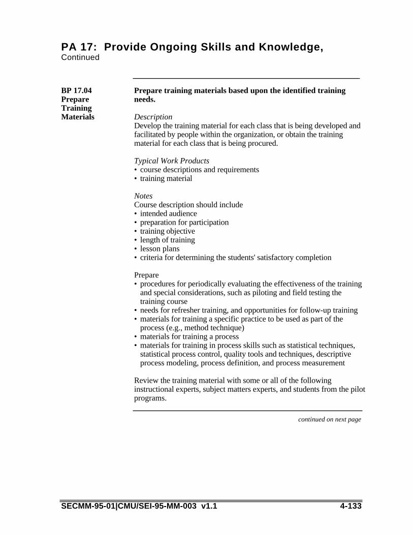
PA 17: Provide Ongoing Skills and Knowledge,Continued
Prepare training materials based upon the identified trainingneeds.
DescriptionDevelop the training material for each class that is being developed andfacilitated by people within the organization, or obtain the trainingmaterial for each class that is being procured.
Typical Work Products• course descriptions and requirements• training material
NotesCourse description should include
BP 17.04PrepareTrainingMaterials
• intended audience• preparation for participation• training objective• length of training• lesson plans• criteria for determining the students' satisfactory completion
Prepare• procedures for periodically evaluating the effectiveness of the training
and special considerations, such as piloting and field testing thetraining course
• needs for refresher training, and opportunities for follow-up training• materials for training a specific practice to be used as part of the
process (e.g., method technique)• materials for training a process• materials for training in process skills such as statistical techniques,
statistical process control, quality tools and techniques, descriptiveprocess modeling, process definition, and process measurement
Review the training material with some or all of the followinginstructional experts, subject matters experts, and students from the pilotprograms.
continued on next page
SECMM-95-01|CMU/SEI-95-MM-003 v1.1 4-133

PA 17: Provide Ongoing Skills and Knowledge,Continued
Train personnel to have the skills and knowledge needed toperform their assigned roles.
DescriptionPersonnel are trained in accordance with the training plan and developedmaterial.
Typical Work Products• trained personnel
NotesOffer the training in a timely manner (just-in-time training) toensure optimal retention and the highest possible skill level.
BP 17.05TrainPersonnel
• A procedure should exist to determine the skill level of the employeeprior to receiving the training to determine if the training is appropriate(i.e., if a trainer waiver or equivalent should be administered to theemployee).
• A process exists to provide incentives and motivate the students toparticipate in the training.
• Online training/customized instruction modules accommodatedifferent learning styles and cultures, in addition to transferringsmaller units of knowledge.
Assess the effectiveness of the training to meet the identifiedtraining needs.
DescriptionA key aspect of training is determining its effectiveness. Methods ofevaluating effectiveness need to be addressed concurrent with thedevelopment of the training plan and training material; in some cases,these methods need to be an integral part of the training material. Theresults of the effectiveness assessment must be reported in a timelymanner so that adjustments can be made to the training.
Typical Work Products• analysis of training effectiveness• modification to training
NotesA procedure should exist to determine the skill level of the employeeafter receiving the training to determine the success of the training. Thiscould be accomplished via formal testing, on-the-job skillsdemonstration, or assessment mechanisms embedded in thecourseware.
BP 17.06Assess TrainingEffectiveness
4-134 SECMM-95-01|CMU/SEI-95-MM-003 v1.1

continued on next page
SECMM-95-01|CMU/SEI-95-MM-003 v1.1 4-135

PA 17: Provide Ongoing Skills and Knowledge,Continued
Maintain records of training and experience.
DescriptionRecords are maintained to track the training that each employee hasreceived and the employee’s skills and capabilities.
Typical Work Products• training and experience records
NotesRecords are kept of all students who successfully complete each trainingcourse or other approved training activity. Also, records of successfullycompleted training are made available for consideration in theassignment of the staff and managers.
BP 17.07MaintainTrainingRecords
Maintain training materials in an accessible repository.
DescriptionCourseware material is maintained in a repository for future access byemployees and for maintaining traceability in changes in coursematerial.
Typical Work Products• baselined training materials• revisions to training materials
NotesMaintain a repository of training materials and make it available to allemployees. (For example, the organization's library could make books,notebooks, videotapes, etc., available; soft-copy training materials couldbe maintained in a public file server.) Incorporate lessons learned intoprocess training materials and the training program. Update processtraining materials with all process changes and improvements.
BP 17.08MaintainTrainingMaterials
End of PA 17: Provide Ongoing Skills and Knowledge
4-136 SECMM-95-01|CMU/SEI-95-MM-003 v1.1

PA 18: Coordinate with Suppliers
The purpose of Coordinate with Suppliers is to address the needs oforganizations to effectively manage the portions of product work thatare conducted by other organizations. Decisions made as a part of thisprocess area should be made in accordance with the Analyze CandidateSolutions process area (PA01). The general term supplier is used toidentify an organization that develops, manufactures, tests, supports,etc., a component of the system. Suppliers may take the form ofvendors, subcontractors, partnerships, etc., as the business organizationwarrants.
In addition to coordination of schedules, processes, and deliveries ofwork products, affected organizations must have a shared a vision of theworking relationship. Relationships can range from integrateddeveloper / supplier product teams, to prime-contractor / subcontractor,to vendors, and more. A successful relationship between anorganization and a supplier depends on the capability of bothorganizations, and on a mutual understanding of the relationship andexpectations.
Summarydescription
When suppliers deliver products that do not meet an organization'sneeds, the organization has the option to change to another supplier,lower its standards and accept the delivered products, or help thesupplier or vendor meet the organization's needs.
The organization acts as the customer when the supplier executes theUnderstand Customer Needs and Expectations process area (PA06).The organization should help the supplier to achieve full understanding.If the supplier does not have the processes to execute this process area,the organization should coach the supplier in getting the necessaryinformation.
Process areanotes
The following list contains the base practices that are essential elementsof good systems engineering: BP.18.01 Identify needed system components or services that must be provided
by other/outside organizations.BP.18.02 Identify suppliers that have shown expertise in the identified areas.BP.18.03 Choose suppliers in accordance with the Analyze Candidate
Solutions process area (PA01).BP.18.04 Provide to suppliers the needs, expectations, and measures of
effectiveness held by the organization for the system components orservices that are to be delivered.
BP.18.05 Maintain timely two-way communication with suppliers.
Base practiceslist
continued on next page
SECMM-95-01|CMU/SEI-95-MM-003 v1.1 4-137

PA 18: Coordinate with Suppliers, Continued
Identify needed system components or services that must beprovided by other/outside organizations.
DescriptionRarely does an organization make every component of the system.Make-vs.-buy analyses and decisions determine which items will beprocured. System needs that will be satisfied outside the organizationare generally those in which the organization has little expertise orinterest.
Typical Work Products• make-vs.-buy trade study• list of system components• sub set of system components for outside organizations to address• list of potential suppliers• beginnings of criteria for completion of needed work
NotesExample practices include• Perform trade study.• Examine own organization to determine missing expertise needed to
address system requirements.
BP 18.01IdentifySystemsComponentsor Services
Identify suppliers that have shown expertise in the identifiedareas.
DescriptionThe capabilities of the supplier should be complementary andcompatible with those of the organization. Issues that may be ofconcern include competent development processes, manufacturingprocesses, responsibilities for verification, on-time delivery, life-cyclesupport processes, and ability to communicate effectively over longdistances (video teleconferencing, electronic file transfers, e-mail and thelike).
Typical Work Products• list of suppliers• advantages and disadvantages of each supplier• potential ways of working over physical distances with suppliers
NotesExample practices include• Read trade journals.• Use available library services.• Use organizational knowledge-base (perhaps an online system).
BP 18.02IdentifyCompetentSuppliers orVendors
4-138 SECMM-95-01|CMU/SEI-95-MM-003 v1.1
continued on next page
SECMM-95-01|CMU/SEI-95-MM-003 v1.1 4-139

PA 18: Coordinate with Suppliers, Continued
Choose suppliers in accordance with the Analyze CandidateSolutions process area (PA01).
DescriptionSuppliers are selected in a logical and equitable manner to meet productobjectives. The characteristics of a supplier which would bestcomplement the organization's abilities are determined, and qualifiedcandidates are identified. The practices of the Analyze CandidateSolutions process area (PA01) are applied to select the appropriatesupplier.
Typical Work Products• organization weaknesses which might be mitigated by a supplier• characteristics of the desired working relationships with the supplier• supplier requirements• customer requirements to be "flowed down" to supplier• selected supplier• captured rationale for selected supplier
NotesAn important consideration in the selection of the supplier is theexpected working relationship. This could range from a highlyintegrated product team to a classical "meet the requirements"relationship. The selection criteria are likely different, depending of thedesired relationship.
BP 18.03ChooseSupplier orVendors
continued on next page
4-140 SECMM-95-01|CMU/SEI-95-MM-003 v1.1

PA 18: Coordinate with Suppliers, Continued
Provide to suppliers the needs, expectations, and measures ofeffectiveness held by the developing organization for the systemcomponents or services that are to be delivered.
DescriptionThe contracting organization must clearly identify and prioritize itsneeds and expectations, as well as any limitations on the part of thesuppliers. The organization works closely with suppliers to achieve amutual understanding of product requirements, responsibilities, andprocesses which will be applied to achieve program objectives.
Typical Work Products• needs statement• technical performance parameters• verification specifications
NotesExamples of techniques and forums for providing needs, expectations,and measures of effectiveness to suppliers or vendors include• trade studies• formal contracts• in-process reviews• joint meetings• payment milestones
BP 18.04ProvideExpectations
continued on next page
SECMM-95-01|CMU/SEI-95-MM-003 v1.1 4-141
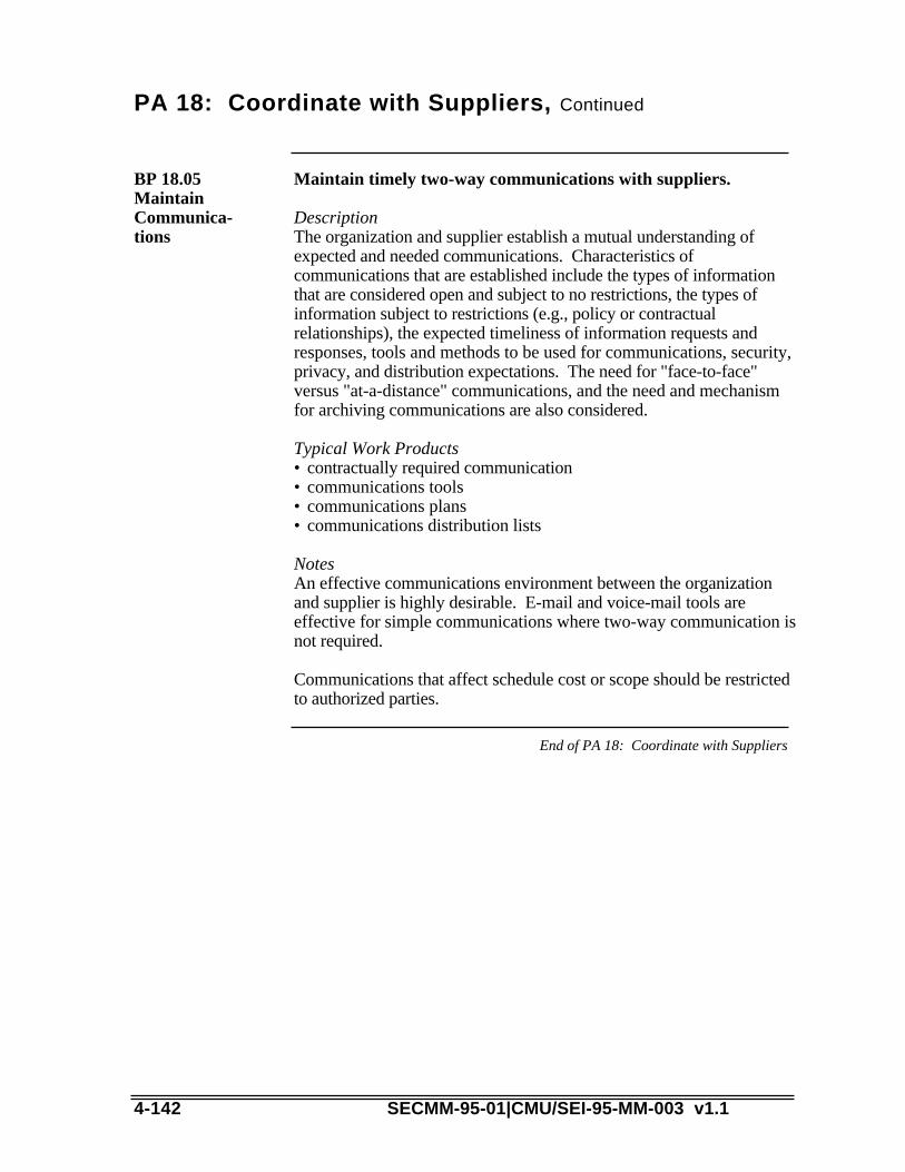
PA 18: Coordinate with Suppliers, Continued
Maintain timely two-way communications with suppliers.
DescriptionThe organization and supplier establish a mutual understanding ofexpected and needed communications. Characteristics ofcommunications that are established include the types of informationthat are considered open and subject to no restrictions, the types ofinformation subject to restrictions (e.g., policy or contractualrelationships), the expected timeliness of information requests andresponses, tools and methods to be used for communications, security,privacy, and distribution expectations. The need for "face-to-face"versus "at-a-distance" communications, and the need and mechanismfor archiving communications are also considered.
Typical Work Products• contractually required communication• communications tools• communications plans• communications distribution lists
NotesAn effective communications environment between the organizationand supplier is highly desirable. E-mail and voice-mail tools areeffective for simple communications where two-way communication isnot required.
Communications that affect schedule cost or scope should be restrictedto authorized parties.
BP 18.05MaintainCommunica-tions
End of PA 18: Coordinate with Suppliers
4-142 SECMM-95-01|CMU/SEI-95-MM-003 v1.1
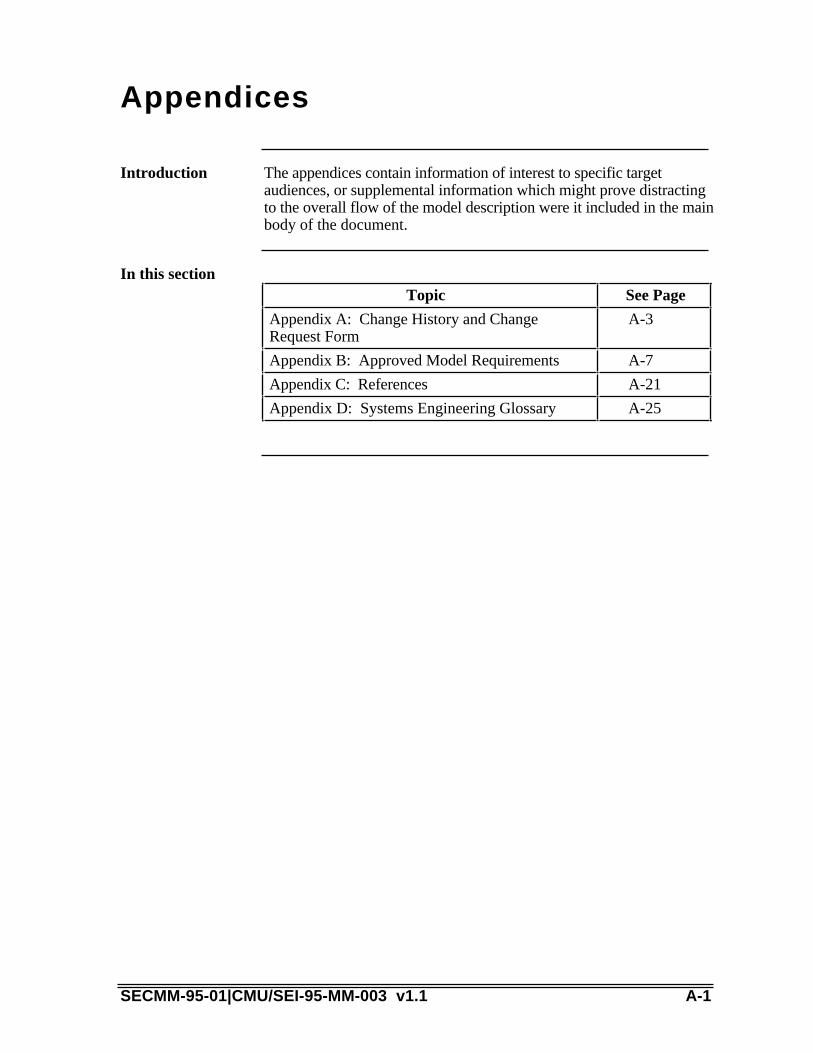
Appendices
The appendices contain information of interest to specific targetaudiences, or supplemental information which might prove distractingto the overall flow of the model description were it included in the mainbody of the document.
Introduction
In this sectionTopic See Page
Appendix A: Change History and ChangeRequest Form
A-3
Appendix B: Approved Model Requirements A-7
Appendix C: References A-21
Appendix D: Systems Engineering Glossary A-25
SECMM-95-01|CMU/SEI-95-MM-003 v1.1 A-1

A-2 SECMM-95-01|CMU/SEI-95-MM-003 v1.1

Appendix A: Change History and Change Request Form
This appendix contains the change history for the SE-CMM and achange request form. Significant changes in focus or content from onerelease to another are highlighted.
Introduction
Table A-1 provides the change history for the SE-CMM:ChangeHistory Table
Version Designator Content Change Notes
Release 1 • architecture rationale
• Process Areas
• ISO (SPICE) BPG0.05 summary
• Glossary
Release 2 WorkshopVersion
• Executive Summary
• Overview of theSE-CMM
• Using the SE-CMM
• Process Areas
• BPG 0.06 withSE-CMM notes
• Model Requirements
• Appendices
• Front matter,overview added
• PA descriptions,boundaries andbase practicesrevised based onWorkshop #1comments
Release 2.02 • Same as release 2Workshop version
• Many TBS’s (tobe supplied) filledin
Table A-1. Change History Table
continued on next page
SECMM-95-01|CMU/SEI-95-MM-003 v1.1 A-3
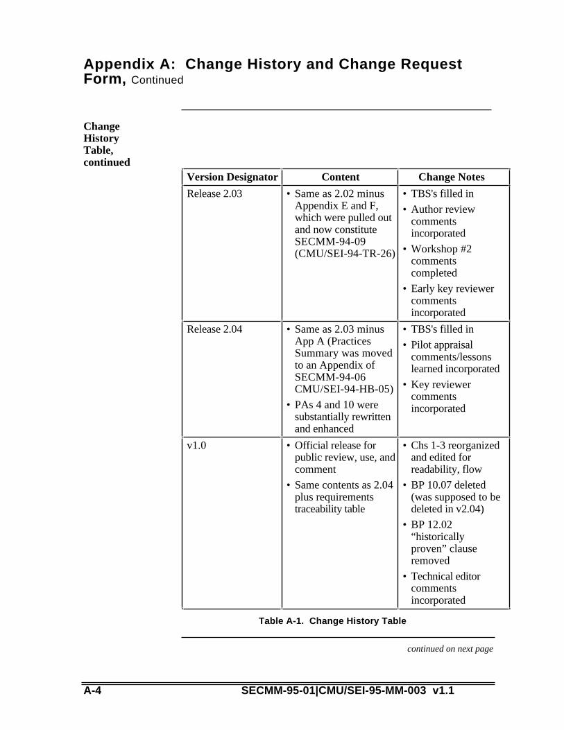
Appendix A: Change History and Change RequestForm, Continued
ChangeHistoryTable,continued
Version Designator Content Change Notes
Release 2.03 • Same as 2.02 minusAppendix E and F,which were pulled outand now constituteSECMM-94-09(CMU/SEI-94-TR-26)
• TBS's filled in
• Author reviewcommentsincorporated
• Workshop #2commentscompleted
• Early key reviewercommentsincorporated
Release 2.04 • Same as 2.03 minusApp A (PracticesSummary was movedto an Appendix ofSECMM-94-06CMU/SEI-94-HB-05)
• PAs 4 and 10 weresubstantially rewrittenand enhanced
• TBS's filled in
• Pilot appraisalcomments/lessonslearned incorporated
• Key reviewercommentsincorporated
v1.0 • Official release forpublic review, use, andcomment
• Same contents as 2.04plus requirementstraceability table
• Chs 1-3 reorganizedand edited forreadability, flow
• BP 10.07 deleted(was supposed to bedeleted in v2.04)
• BP 12.02“historicallyproven” clauseremoved
• Technical editorcommentsincorporated
Table A-1. Change History Table
continued on next page
A-4 SECMM-95-01|CMU/SEI-95-MM-003 v1.1
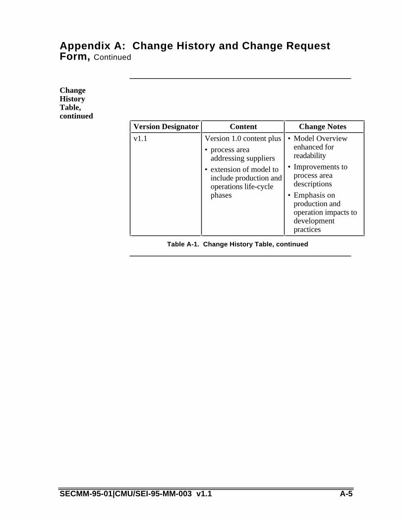
Appendix A: Change History and Change RequestForm, Continued
ChangeHistoryTable,continued
Version Designator Content Change Notes
v1.1 Version 1.0 content plus
• process areaaddressing suppliers
• extension of model toinclude production andoperations life-cyclephases
• Model Overviewenhanced forreadability
• Improvements toprocess areadescriptions
• Emphasis onproduction andoperation impacts todevelopmentpractices
Table A-1. Change History Table, continued
SECMM-95-01|CMU/SEI-95-MM-003 v1.1 A-5

Issues Form for SECMM-95-01 Version 1.1
Please provide your name and organizational affiliation.Reviewer InformationReviewer Name Reviewer Orgn Contact Phone #
If using hardcopy, you may attach several forms together with the nameon just the first one.
Please list the page #(s) or other reference (e.g., "global," "Chapter 3,""Glossary") to which this issue applies. Attach the page for reference ifappropriate.
IssueReference
Please characterize the issue as a problem (e.g., the glossary is notdetailed enough to support...) vs. a solution (e.g., add more detail to theglossary), so that the authors can understand the cause of the issue, notjust the suggested fix. Include your rationale for highlighting the issue,if appropriate.
IssueStatement
This issue is ________ out of my top 10 issues with the SE-CMMVersion 1.1.
Prioritization
Please evaluate the impact the stated problem has on your use of theSE-CMM according to this scale:
____ High Impact: can't use model as intended without problembeing fixed.
____ Medium Impact: misleading or otherwise incorrect content ofsignificance to the reviewer.
____ Low Impact: content error of low significance to reviewer.
ImpactAssessment
For typographical/grammatical/punctuation edits, please forward theredlined pages without the issue form attachment.
Note: editorialissues
A-6 SECMM-95-01|CMU/SEI-95-MM-003 v1.1
Appendix B: Approved Model Requirements
This appendix consists of the requirements document for the SE-CMMthat was approved by the SE-CMM Steering Group for v1.0 of the SE-CMM.
Introduction
The requirements traceability matrix for this product is included at theend of this appendix.
Requirementstraceability
Requests for requirements changes may be submitted directly to amember of the SE-CMM Steering Group or to the SE-CMM ProjectOffice for consideration. An “issues form” is included at the back ofthe SE-CMM. The SE-CMM Steering Group is the approval authorityfor any requirements changes.
Requirementschanges
As a result of the meeting held in October 1994, the followingrequirements changes were approved. The new requirement is whatappears in this version of the model.• Requirement 5.3.5.2.2 was deleted (example practices).• Requirements 5.3.4 and 6.2.1.2 were deleted as requirements of the
model. However, they are the guiding requirements for a newdocument approved by the steering group, SECMM-94-09(CMU/SEI-94-HB-06), Relationships Between the SE-CMM andOther Products.
• Requirement 6.1.2 was modified to permit v1.0 to cover only theproduct development portion of the product life cycle.
continued on next page
SECMM-95-01|CMU/SEI-95-MM-003 v1.1 A-7

Appendix B: Approved Model Requirements, Continued
1.0 Document Overview
1.1.Introduction
A fundamental assumption of maturity models is that the quality of aproduct depends upon the process used for development, the technologyand tools used in development, and the capabilities of the people who dothe work. The CMM for Software primarily covered the process fordevelopment, although aspects of people, facility and training issueswere also covered to a certain extent. Eventually the SE-CMM shouldcover all three areas thoroughly. However, the initial version of the SE-CMM will only have coverage of non-process issues similar to that inthe CMM for Software.
To have merit, a validated appraisal methodology must be used inconjunction with a representative model in order to effectively measurethe capability and maturity of a systems engineering project ororganization. This document identifies the requirements that one half ofthat methodology, a Systems Engineering-Capability Maturity Model(SE-CMM), must meet.
Approach
The quality of a product is a direct function of the process, technology,and tools used and the capability of the people assigned to do the work.The SE-CMM Project recognizes and supports the validity andinterconnectivity of that assumption. However, the initial efforts of theproject have been focused on modeling the characteristics of processesused to implement and institutionalize sound systems engineeringpractices within an organization. Until a follow-on activity expands theSE-CMM to fully address the technology, tools, and people elementscited, a sense of their impact will be captured by using "base practices"which address primarily process-related elements, but will overlap, insome cases, into non-process areas.
Growth
continued on next page
A-8 SECMM-95-01|CMU/SEI-95-MM-003 v1.1

Appendix B: Approved Model Requirements, Continued
In the following sections, the term 'will' indicates a mandatoryrequirement. The usage of "will" in this document corresponds to theuse of the term "shall" in Government requirements.
Elements which are not mandatory, but which have sufficient merit towarrant that the Project include them to the extent possible, are identifiedby the term "should."
1.2.Requirementsterminology
Section 2.0 outlines the overall Project goal. With that exception, thisdocument is strictly limited to requirements imposed on the modelportion of the SE-CMM Project. Information on the appraisal portioncan be found in a separate document titled, SE-CMM Appraisal MethodDescription (SE-CMM-94-06).
1.3.Scope of thisdocument
2.0 Goal
The overall goal of the SE-CMM Project is to provide a SystemsEngineering Capability Maturity Model and appraisal methodology that:
1) Supports industry-wide improvement of systems engineeringactivities, and2) Provides an accepted frame of reference for the appraisal of anorganization's systems engineering capabilities.
2.1Model andappraisalmethod
3.0 Objectives
In support of the Project goals, the model should seek to achieve thefollowing objectives.
Introduction
The SE-CMM should seek to obtain and maintain acceptance of themodel by both industry and government organizations.
3.1.Industryacceptance
continued on next page
SECMM-95-01|CMU/SEI-95-MM-003 v1.1 A-9

Appendix B: Approved Model Requirements, Continued
The SE-CMM should seek to avoid conflict with existing and emergingstandards and initiatives (e.g., ISO 9001, draft Mil-Std-499B). In thiscontext, "avoid conflict" means that the SE-CMM should notknowingly encourage activities or provide process guidance whichcontradicts appropriate emerging standards.
3.2.Compatibility
4.0 Scope of the Model
The SE-CMM will focus on the systems engineering processesexecuted by systems engineering practitioners and managers. Supportareas will be considered where necessary.
4.1 Focus
The SE-CMM will be applicable to a generalized, rather than aspecifically instantiated, process.
4.2Applicability
4.3Incrementaldevelopment
Version 1.0 of the SE-CMM will focus on process capabilityimprovement and assessment.
4.3.1 Initialversion
Subsequent versions of the SE-CMM will evolve and refine processcoverage, based on field experience, and expand the ability of the modelto assess additional dimensions of a project or organization's capabilityand maturity, such as human resource capacity and the effectiveness ofavailable tools.
4.3.2 Growth
The Model will address systems engineering down to, but notincluding, the various implementation disciplines (e.g., hardware,firmware, and software development).
4.4 Depth ofcoverage
continued on next page
A-10 SECMM-95-01|CMU/SEI-95-MM-003 v1.1
Appendix B: Approved Model Requirements, Continued
4.5Applicability
4.5.1 Numberof projects
The SE-CMM will be applicable regardless of the number (one, ormore than one) of projects being implemented by a systems engineeringorganization.
The SE-CMM will be applicable to the assessment or evaluation of asystems engineering organization, regardless of size.
4.5.2 Scaling,or size
5.0 Model Description
Purpose This section describes the content of a specific ProjectProduct/Deliverable titled, SE-CMM Model Description (SECMM-94-04). The names of the sections of the document shown here maychange in the final document to improve its readability.
This section will contain a brief overview of the model, its history andpurpose, advantages, and constraints coupled with a brief, basic outlineof how the document is constructed and how topics are linked.
5.1 Executivesummary
This section will formally introduce the reader to the document. It willcontain a brief history of the Project, a short discussion of how theProject is organized, and an outline of future plans. Project workproducts (and their content) will be identified and their relationship tothe model described.
5.2Introduction
This section describes the model in detail. It will contain, as aminimum, the following elements.
5.3 Modeldescription
continued on next page
SECMM-95-01|CMU/SEI-95-MM-003 v1.1 A-11

Appendix B: Approved Model Requirements, Continued
In this section, a brief description of the scope of the model and itsintended audience will be provided.
5.3.1Applicability
A detailed description of model components will be provided.Relationships and interactions between and among the variouscomponents of the model will be shown. Constraints and cautions, ifany, will also be provided in this section.
5.3.2Architecture
<deleted per Steering Group 10/12 - moved to SECMM-94-09>(CMU/SEI-94-HB-06)
5.3.3Interactionwith similarmaturitymodels
The term "practices" will, with specific adjectives, designate thosecharacteristics which are considered essential and those which providean advisory function.
5.3.4 SE-CMMpractices
Following are general characteristics applicable to all practices.5.3.4.1Practicedependencies
Practices will be organizationally independent.5.3.4.1.1Organizationdependencies
Practices will be product independent.5.3.4.1.2Productdependencies
continued on next page
A-12 SECMM-95-01|CMU/SEI-95-MM-003 v1.1

Appendix B: Approved Model Requirements, Continued
The model will identify, as a minimum, a set of specific tasks whichmust be accomplished in order to achieve a satisfactory systemsengineering outcome. These tasks will be identified as "Base Practices"and grouped according to the specific Process Area with which they areassociated.
5.3.4.2 Basepractices
A description of each Base Practice will be provided which shoulddescribe the practice, provide interpretation guidelines, clearly identifythe intended usage, and show how the practice interacts with others.
5.3.4.2.1Usage/interpretationguidelines
A glossary of all systems engineering terms used in the SE-CMM willbe provided as an appendix.
5.4Glossary
Subsequent appendices will be provided on an as needed basis.5.5Appendix
6.0 Constraints
6.1Modelcharacteristics
The SE-CMM will include practices to identify good systemengineering management characteristics. Overall program/projectmanagement techniques should be considered only to the extent theyimpact systems engineering task execution.
6.1.1Managementcharacteristics
continued on next page
SECMM-95-01|CMU/SEI-95-MM-003 v1.1 A-13

Appendix B: Approved Model Requirements, Continued
The SE-CMM will eventually address planning and performance overthe entire range of systems engineering activities throughout thecomplete systems engineering life cycle. Version 1.0 covers theproduct development cycle only.
6.1.2Life-cyclecoverage
The SE-CMM will be structured so the decomposition of each leveldownward is readily apparent and traceable either from top down, orbottom up.
6.1.3Structure
The SE-CMM will be functionally decomposed into areas directlyrelatable to management, process designers, and practitioners.
6.1.4Functionality
6.2.Relationshipsto othercapability/maturitymodels
<requirement moved to SECMM-94-09 (CMU/SEI-94-HB-06)>6.2.1CMM forsoftware
<requirement moved to SECMM-94-09 (CMU/SEI-94-HB-06)>6.2.1.1Terminology
The SE-CMM should be easily relatable to the CMM for Software.6.2.1.2Interfaces
continued on next page
A-14 SECMM-95-01|CMU/SEI-95-MM-003 v1.1
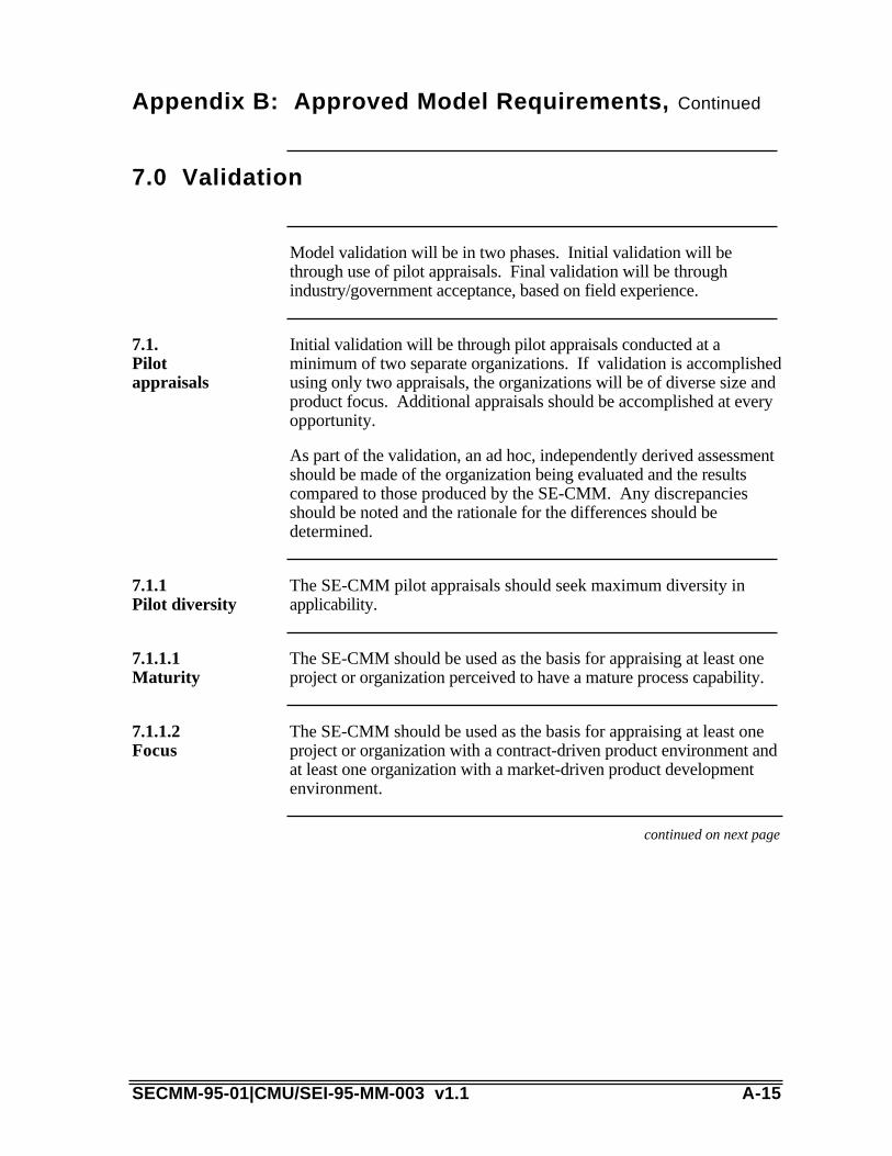
Appendix B: Approved Model Requirements, Continued
7.0 Validation
Model validation will be in two phases. Initial validation will bethrough use of pilot appraisals. Final validation will be throughindustry/government acceptance, based on field experience.
Initial validation will be through pilot appraisals conducted at aminimum of two separate organizations. If validation is accomplishedusing only two appraisals, the organizations will be of diverse size andproduct focus. Additional appraisals should be accomplished at everyopportunity.
As part of the validation, an ad hoc, independently derived assessmentshould be made of the organization being evaluated and the resultscompared to those produced by the SE-CMM. Any discrepanciesshould be noted and the rationale for the differences should bedetermined.
7.1.Pilotappraisals
The SE-CMM pilot appraisals should seek maximum diversity inapplicability.
7.1.1Pilot diversity
7.1.1.1Maturity
The SE-CMM should be used as the basis for appraising at least oneproject or organization perceived to have a mature process capability.
The SE-CMM should be used as the basis for appraising at least oneproject or organization with a contract-driven product environment andat least one organization with a market-driven product developmentenvironment.
7.1.1.2Focus
continued on next page
SECMM-95-01|CMU/SEI-95-MM-003 v1.1 A-15
Appendix B: Approved Model Requirements, Continued
Derivation and Traceability of SE-CMM Requirements
Instruction The requirements herein contained were produced using materialgarnered from project participants as recorded in the documents listedbelow. A specific listing of author's meetings and copies of the minutesare available, upon request. Following the sources list is a traceabilitymatrix of SE-CMM requirements to the sections of the model thatgenerally cover the requirement.
1. Minutes, Potential Project Participants Meeting, September 27, 19932. NCOSE Request for Information on Capability Assessments3. Minutes, SE-CMM Steering Group Meeting, January 27, 19944. Minutes, several SE-CMM Authors Meetings5. Minutes, October 10-12, 1994 Steering Group Meeting
Sources list
continued on next page
A-16 SECMM-95-01|CMU/SEI-95-MM-003 v1.1

Appendix B: Approved Model Requirements, Continued
TraceabilityMatrix
Req.Number
RequirementName
TextLocation
1.0 Document Overview N/A
1.1 Introduction N/A
1.2 Requirements Terminology Appendix B
1.3 Scope of This Document 1.1 About this Document,SECMM-94-06(CMU/SEI-94-HB-05)
2.0 Goal N/A
2.1 Model and Appraisal Method Throughout
3.0 Objectives N/A
3.1 Industry Acceptance 1.2 About the SE-CMMProject
3.2 Compatibility Chapter 4: The SE-CMMGeneric & Base Practices
SECMM-94-09(CMU/SEI-94-HB-06)
4.0 Scope of Model N/A
4.1 Focus Chapter 4: The SE-CMMGeneric & Base Practices
4.2 Applicability Chapter 4: The SE-CMMGeneric & Base Practices
2.3 SE-CMM ArchitectureDescription
4.3 Incremental Development N/A
4.3.1 Initial Version 2.1 SE-CMM Foundations
Table A-2. Traceability Matrix
continued on next page
SECMM-95-01|CMU/SEI-95-MM-003 v1.1 A-17
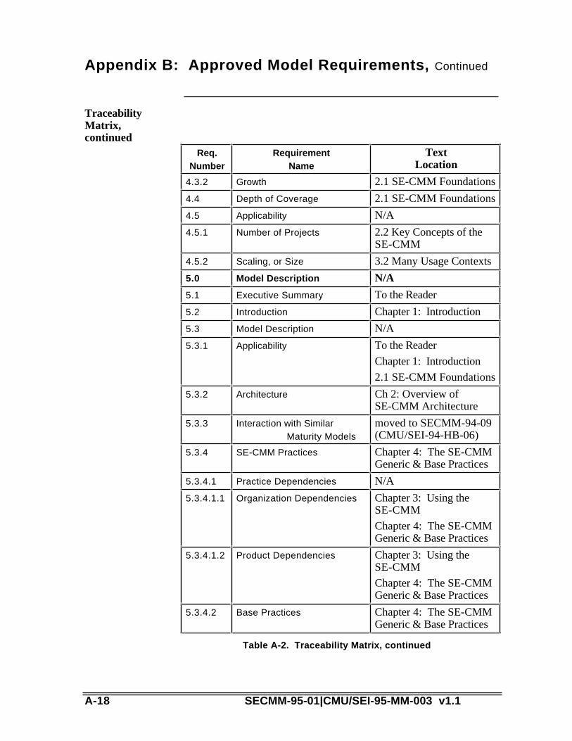
Appendix B: Approved Model Requirements, Continued
TraceabilityMatrix,continued
Req.Number
RequirementName
TextLocation
4.3.2 Growth 2.1 SE-CMM Foundations
4.4 Depth of Coverage 2.1 SE-CMM Foundations
4.5 Applicability N/A
4.5.1 Number of Projects 2.2 Key Concepts of theSE-CMM
4.5.2 Scaling, or Size 3.2 Many Usage Contexts
5.0 Model Description N/A
5.1 Executive Summary To the Reader
5.2 Introduction Chapter 1: Introduction
5.3 Model Description N/A
5.3.1 Applicability To the Reader
Chapter 1: Introduction
2.1 SE-CMM Foundations
5.3.2 Architecture Ch 2: Overview ofSE-CMM Architecture
5.3.3 Interaction with SimilarMaturity Models
moved to SECMM-94-09(CMU/SEI-94-HB-06)
5.3.4 SE-CMM Practices Chapter 4: The SE-CMMGeneric & Base Practices
5.3.4.1 Practice Dependencies N/A
5.3.4.1.1 Organization Dependencies Chapter 3: Using theSE-CMM
Chapter 4: The SE-CMMGeneric & Base Practices
5.3.4.1.2 Product Dependencies Chapter 3: Using theSE-CMM
Chapter 4: The SE-CMMGeneric & Base Practices
5.3.4.2 Base Practices Chapter 4: The SE-CMMGeneric & Base Practices
Table A-2. Traceability Matrix, continued
A-18 SECMM-95-01|CMU/SEI-95-MM-003 v1.1

continued on next page
SECMM-95-01|CMU/SEI-95-MM-003 v1.1 A-19

Appendix B: Approved Model Requirements, Continued
TraceabilityMatrix,continued
Req.Number
RequirementName
TextLocation
5.3.4.2.1 Usage/InterpretationGuidelines
Chapter 4: The SE-CMMGeneric & Base Practices
5.4 Glossary Appendix D: Glossary
5.5 Appendix Appendices A-C
6.0 Constraints N/A
6.1 Model Characteristics N/A
6.1.1 Management Characteristics 2.1 SE-CMM Foundations
Chapter 4: The SE-CMMGeneric & Base Practices
6.1.2 Life-cycle coverage 2.1 SE-CMM Foundations
Chapter 4: The SE-CMMGeneric & Base Practices
6.1.3 Structure 2.3 SE-CMM ArchitectureDescription
Ch. 4: The SE-CMMGeneric & Base Practices
6.1.4 Functionality Chapter 4: The SE-CMMGeneric & Base Practices
6.2 Relationships to Other CMMs N/A
6.2.1 CMM for Software N/A
6.2.1.1 Terminology Whole document
6.2.1.2 Interfaces SECMM-94-09(CMU/SEI-94-HB-06)
7.0 Validation N/A
7.1 Pilot Appraisals See SE-CMM PilotAppraisal Report
7.1.1 Pilot Diversity See SE-CMM PilotAppraisal Report
7.1.1.1 Maturity See SE-CMM PilotAppraisal Report
7.1.1.2 Focus See SE-CMM PilotAppraisal Report
A-20 SECMM-95-01|CMU/SEI-95-MM-003 v1.1

Table A-2. Traceability Matrix, continued
SECMM-95-01|CMU/SEI-95-MM-003 v1.1 A-21

A-22 SECMM-95-01|CMU/SEI-95-MM-003 v1.1

Appendix C: References
This appendix provides the references for documents cited within theSE-CMM, as well as selected bibliographic sources for concepts.
Introduction
[AFMC] AF 800-Software Development CapabilityEvaluation (SDCE).
[Blanchard 81] Blanchard, Benjamin S.; & Fabrycky, Walter J.Systems Engineering and Analysis. EnglewoodCliffs, N.J.: Prentice-Hall, 1981.
[Charette 89] Charette, Robert N. Software Engineering, RiskAnalysis and Management. New York: IntertextPublications, McGraw-Hill, 1989.
[Chestnut 67] Chestnut, Harold. Systems Engineering Methods.New York, NY: John Wiley & Sons, 1967.
[Crab 93] Crab, Don. “The New PCs.” PC Magazine 12(June 15, 1993): 109-170.
[Defense 86] Defense Systems Management College. SystemsEngineering Management Guide. Washington, D.C.:U. S. Government Printing Office, 1986.
[Eisner 88] Eisner, Howard. Computer Aided SystemsEngineering. New Jersey: Prentice Hall, 1988.
[Fagan 76] Fagan, Michael. "Software Inspections." IBMSystems Research Journal (September 1976).
[FM 770-78] USALMC Army Field Manual, "SystemsEngineering," Training Support Center, Ft. Eustis(804-878-4668).
[Foster 93] Foster, Kenneth R. “Math, Visualization, and DateAcquisition.” IEEE Spectrum 30 (November1993): 42-59.
[Geppert 94] Geppert, Linda. "Faults and Failures." IEEESpectrum. (August 1994): 17.
[Hall 62] Hall, Arthur D. A Methodology for SystemsEngineering. Princeton, N.J.: Van NostrandCompany. 1962.
ReferenceList
SECMM-95-01|CMU/SEI-95-MM-003 v1.1 A-23
continued on next page
A-24 SECMM-95-01|CMU/SEI-95-MM-003 v1.1

Appendix C: References, Continued
SECMM-95-01|CMU/SEI-95-MM-003 v1.1 A-25

Reference list,continued
[Herbsleb 94] Herbsleb, James, et al. Benefits of CMM-BasedSoftware Process Improvement: Initial Results,(CMU/SEI-94-TR-13), Pittsburgh, PA: SoftwareEngineering Institute, Carnegie Mellon University,August, 1994.
[Humphrey 87] Humphrey, Watts. Characterizing the SoftwareProcess Maturity of Contractors PreliminaryReport, (CMU/SEI-87-TR-23, ADA 187230),Pittsburgh, PA: Software Engineering Institute,Carnegie Mellon University, September, 1987.
[IEEE 90] Dictionary of Computing Terms, IEEE 630-90,1990.
[IEEE 93] IEEE P1220. IEEE Standard for SystemsEngineering, Preliminary, 1993.
[INCOSE 92b] International Council on Systems Engineering(INCOSE), INSIGHT (Issue 9, September 1995): 6.
[Kornbluh 93] Kornbluh, Ken. “Seeing Data in Action," IEEESpectrum 30 (November 1993): 60-75.
[Lacy 92] Lacy, James A. Systems Engineering Management,Achieving Total Quality. New York: McGraw-Hill,Inc. 1992.
[Lano 90] Lano, R. J., “The N2 Chart,” 244-27. System andSoftware Requirements Engineering. Thayer,Richard & Dorfman, Merlin, eds. Washington:IEEE Computer Society Press, 1990.
[McAuley 93] McAuley, James E.; & McCumber, William H. eds.Proceedings of the Third Annual InternationalSymposium of the National Council on SystemsEngineering, 1993.
[MIL-STD-499B] Draft Systems Engineering Standard, AFMC, 1994.
[Miller 56] Miller, George. “The Magical Number Seven, Plusor Minus Two.” Psychological Review 63 (1956):81-97.
[Mish 86] Mish, Frederick C., ed. Webster’s Ninth NewCollegiate Dictionary. Springfield: Merriam-Webster. 1986.
continued on next page
A-26 SECMM-95-01|CMU/SEI-95-MM-003 v1.1

Appendix C: References, Continued
[Morgello 91] Morgello, Clem. "George Fisher of Motorola: theQuest for Quality." Institutional Investor (1991):Volume 25, Number 9, 45-46.
[NCOSE 92a] National Council on Systems Engineering(NCOSE), Membership flier, 1992.
[NCOSE 92b] NCOSE. Introduction to NCOSE, 1992.
[NCOSE 93] NCOSE Capability Assessment Working Group(CAWG) Request for Information for SystemsEngineering Capability Maturity Models, 1993.
[O’Boyle 90] O’Boyle, Thomas F. “GE Refrigerator WoesIllustrate the Hazards in Changing a Product,” WallStreet Journal 1 (May 7, 1990).
[Paulk 91] Paulk, Mark, et. al. A Capability Maturity Model forSoftware, (CMU/SEI-91-TR-24, ADA 240603).Pittsburgh, PA: Software Engineering Institute,Carnegie Mellon University, August 1991.
[Paulk 93a] Paulk, Mark; Curtis, William; & Chrissis, MaryBeth. A Capability Maturity Model for Software v1.1,(CMU/SEI-93-TR-24, ADA 263403). Pittsburgh,PA: Software Engineering Institute, Carnegie MellonUniversity, February 1993.
[Paulk 93b] Paulk, Mark; Weber, Charles; Garcia, Suzanne;Bush, Marilyn; & Chrissis, Mary Beth. KeyPractices for the Capability Maturity Model forSoftware v1.1, (CMU/SEI-93-TR-25, ADA263432). Pittsburgh, PA: Software EngineeringInstitute, Carnegie Mellon University, February1993.
[Sage 77] Sage, Andrew P. Methodology for Large-ScaleSystems. New York: McGraw-Hill, 1977.
[Sailor 90] Sailor, J. Douglas. “System Engineering: AnIntroduction,” System and Software RequirementsEngineering. Thayer, Richard; & Dorfman, Merlin,eds. Washington: IEEE Computer Society Press,1990: 35-47.
Reference list,continued
continued on next page
SECMM-95-01|CMU/SEI-95-MM-003 v1.1 A-27
Appendix C: References, Continued
[Schmidt 92] Schmidt, Stephen R.; & Launsby, Robert G.Understanding Industrial Designed Experiments.Colorado Springs, CO: Air Academy Press, 1992.
[Sedrick 91] Sedrick, Greg, ed. “A Commitment to Success,”Proceedings of the American Society forEngineering Management and the National Councilon Systems Engineering. NCOSE, 1991.
[Small 93] Small, Charles H. “Workstations vs PCs,” EDN 38(March 18, 1993):164-174.
[Weber 91] Weber, Charles, et al., Key Practices for theCapability Maturity Model for Software,(CMU/SEI-91-TR-25, ADA 2640604) Pittsburgh,PA: Software Engineering Institute, Carnegie MellonUniversity, August 1991.
[Wheelwright 92] Wheelwright, Steven C.; & Clark, Kim B.Revolutionizing Product Development: QuantumLeaps in Speed, Efficiency and Quality. New York:New York Press, 1992.
[Wood 91] Wood, David P. Extending Process ModelingAccuracy (CMU/SEI-91-SR-10) Pittsburgh, PA:Software Engineering Institute, Carnegie MellonUniversity, 1991.
[Wymore 76] Wymore, A. Wayne. Systems EngineeringMethodology for Interdisciplinary Teams. NewYork: John Wiley & Sons, 1976.
[Zajak 92] Zajak, Blair. “Enhanced System EngineeringEfficiency in the 21st Century,” Proceedings of theSecond Annual International Symposium of theNational Council on Systems Engineering.Morrison, Arthur F.; & Wirth, John M., eds.NCOSE, 1992.
Reference list,continued
A-28 SECMM-95-01|CMU/SEI-95-MM-003 v1.1

Appendix D: Systems Engineering Glossary
We developed the following glossary for use with all SE-CMM workproducts. Therefore, some terms are defined which are not, at present,included in this document. A common glossary approach was chosenbecause many terms used in the systems engineering world look thesame, but convey differing and sometimes conflicting meanings,depending on the background of the author and reader. By placing allthe terms in a common location, in a common context, we hope to helpyou understand the systems engineering concepts, while promotingcontinuity across the product line.
We chose these definitions from a wide spectrum of sources, includingindustrial, government, and societal standards, modified only to theextent needed to place them in the SE-CMM context. The source of theinformation has been provided whenever possible.
Definitions with a reference of [SECMM] indicate definitions that weproduced as part of the SE-CMM Project.
Introduction
SECMM-95-01|CMU/SEI-95-MM-003 v1.1 A-29

A-30 SECMM-95-01|CMU/SEI-95-MM-003 v1.1
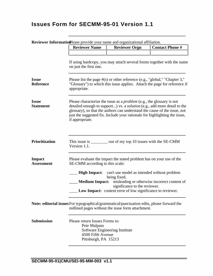
Issues Form for SECMM-95-01 Version 1.1
Please provide your name and organizational affiliation.Reviewer InformationReviewer Name Reviewer Orgn Contact Phone #
If using hardcopy, you may attach several forms together with the nameon just the first one.
Please list the page #(s) or other reference (e.g., "global," "Chapter 3,""Glossary") to which this issue applies. Attach the page for reference ifappropriate.
IssueReference
Please characterize the issue as a problem (e.g., the glossary is notdetailed enough to support...) vs. a solution (e.g., add more detail to theglossary), so that the authors can understand the cause of the issue, notjust the suggested fix. Include your rationale for highlighting the issue,if appropriate.
IssueStatement
This issue is ________ out of my top 10 issues with the SE-CMMVersion 1.1.
Prioritization
Please evaluate the impact the stated problem has on your use of theSE-CMM according to this scale:
____ High Impact: can't use model as intended without problembeing fixed.
____ Medium Impact: misleading or otherwise incorrect content ofsignificance to the reviewer.
____ Low Impact: content error of low significance to reviewer.
ImpactAssessment
For typographical/grammatical/punctuation edits, please forward theredlined pages without the issue form attachment.
Note: editorial issues
Please return Issues Forms to:Pete MalpassSoftware Engineering Institute4500 Fifth AvenuePittsburgh, PA 15213
Submission
SECMM-95-01|CMU/SEI-95-MM-003 v1.1

Systems Engineering Glossary, continued
The criteria that a system or component must satisfy in order to be accepted by a user, customer, or other authorized entity.
acceptance criteria
[ ]IEEE 90
(1) A task assigned to an individual or group for disposition. (2) An action proposal that has been accepted.
action item
[ ]SECMM
A description of the tasks necessary to implement a key process area. Activities Performed typically involve establishing plans and procedures, performing the work, tracking it, and taking corrective actions as necessary.
activities performed
[ ]SECMM
Any step taken or function performed (mental, physical, or both) toward achieving an intended objective.
activity
[ ]SECMM
(1) The process of distributing requirements, resources, or other entities among the components of a system or program.(2) The results of the distribution in (1).
allocation
[ ]IEEE 90
A bounded set of related systems, i.e., systems that address a particular type of problem. Development and maintenance in an application domain usually requires special skills and/or resources. Examples include payroll and personnel systems, command and control systems, compilers, and expert systems.
application domain
[ ]Paulk 93b
A comparison of an implemented process to a process maturity model. Software process assessments and software capability evaluations are examples.
appraisal
[ ]SECMM
The organizational structure of a system or component.architecture[ ]IEEE 90
A characteristic of an item; for example, the item’s color, size, or type.
attribute
[ ]IEEE 90
SECMM-94-04|CMU/SEI-94-HB-4 v1.0 A-26
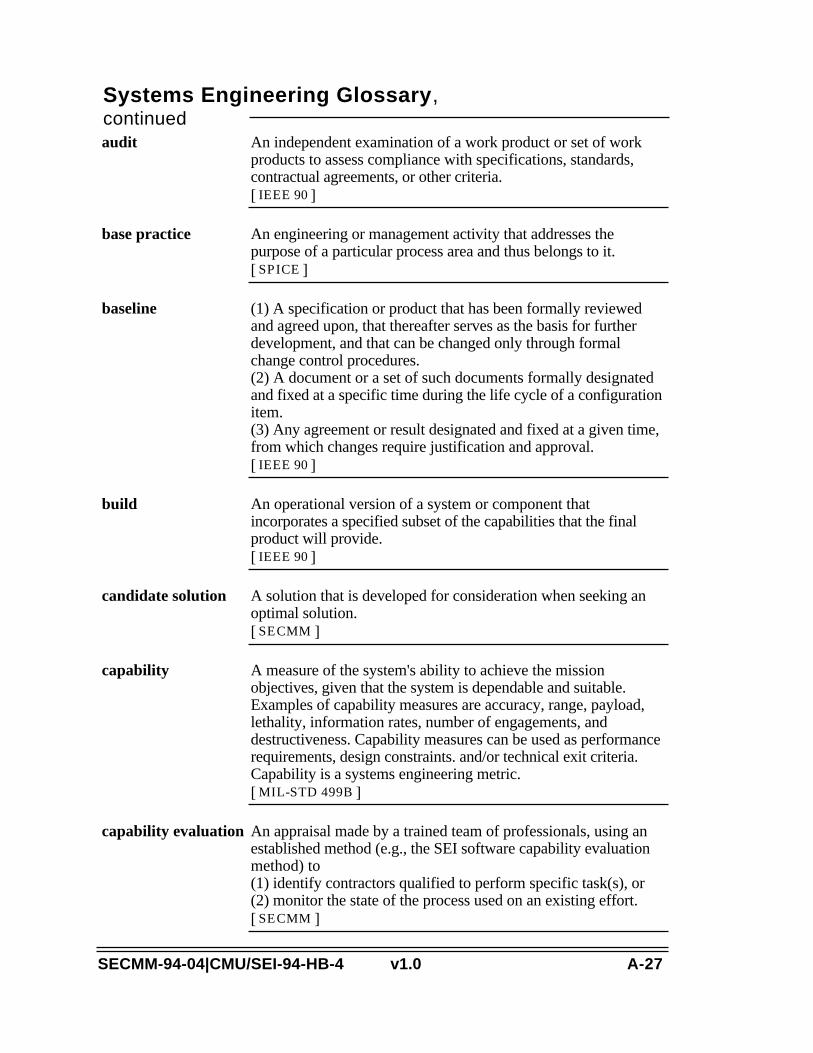
Systems Engineering Glossary, continued
An independent examination of a work product or set of work products to assess compliance with specifications, standards, contractual agreements, or other criteria.
audit
[ ]IEEE 90
An engineering or management activity that addresses the purpose of a particular process area and thus belongs to it.
base practice
[ ]SPICE
(1) A specification or product that has been formally reviewed and agreed upon, that thereafter serves as the basis for further development, and that can be changed only through formal change control procedures.(2) A document or a set of such documents formally designated and fixed at a specific time during the life cycle of a configuration item.(3) Any agreement or result designated and fixed at a given time, from which changes require justification and approval.
baseline
[ ]IEEE 90
An operational version of a system or component that incorporates a specified subset of the capabilities that the final product will provide.
build
[ ]IEEE 90
A solution that is developed for consideration when seeking an optimal solution.
candidate solution
[ ]SECMM
A measure of the system's ability to achieve the mission objectives, given that the system is dependable and suitable. Examples of capability measures are accuracy, range, payload, lethality, information rates, number of engagements, and destructiveness. Capability measures can be used as performance requirements, design constraints. and/or technical exit criteria. Capability is a systems engineering metric.
capability
[ ]MIL-STD 499B
An appraisal made by a trained team of professionals, using an established method (e.g., the SEI software capability evaluation method) to (1) identify contractors qualified to perform specific task(s), or (2) monitor the state of the process used on an existing effort.
capability evaluation
[ ]SECMM
SECMM-94-04|CMU/SEI-94-HB-4 v1.0 A-27
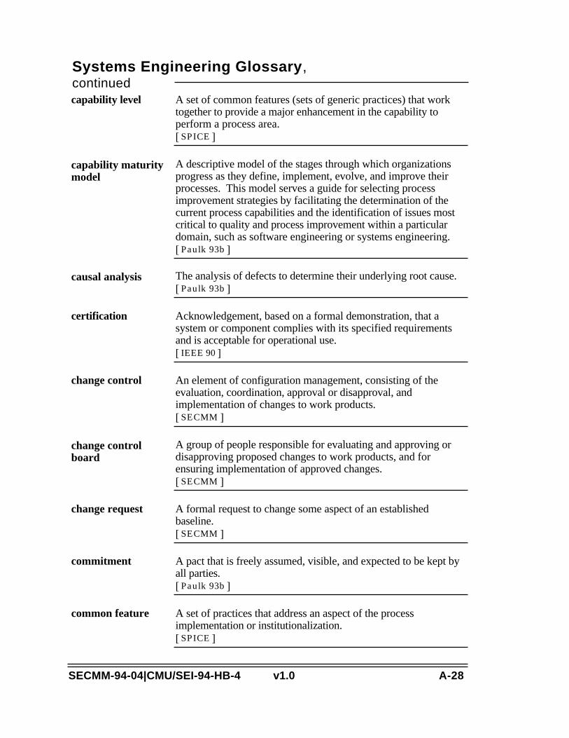
Systems Engineering Glossary, continued
A set of common features (sets of generic practices) that work together to provide a major enhancement in the capability to perform a process area.
capability level
[ ]SPICE
A descriptive model of the stages through which organizations progress as they define, implement, evolve, and improve their processes. This model serves a guide for selecting process improvement strategies by facilitating the determination of the current process capabilities and the identification of issues most critical to quality and process improvement within a particular domain, such as software engineering or systems engineering.
capability maturity model
[ ]Paulk 93b
The analysis of defects to determine their underlying root cause.causal analysis[ ]Paulk 93b
Acknowledgement, based on a formal demonstration, that a system or component complies with its specified requirements and is acceptable for operational use.
certification
[ ]IEEE 90
An element of configuration management, consisting of the evaluation, coordination, approval or disapproval, and implementation of changes to work products.
change control
[ ]SECMM
A group of people responsible for evaluating and approving or disapproving proposed changes to work products, and for ensuring implementation of approved changes.
change control board
[ ]SECMM
A formal request to change some aspect of an established baseline.
change request
[ ]SECMM
A pact that is freely assumed, visible, and expected to be kept by all parties.
commitment
[ ]Paulk 93b
A set of practices that address an aspect of the process implementation or institutionalization.
common feature
[ ]SPICE
SECMM-94-04|CMU/SEI-94-HB-4 v1.0 A-28
Systems Engineering Glossary, continued
(1) The ability of two or more systems or components to perform their required functions while sharing the same environment.(2) The ability of two or more systems or components to exchange information.
compatibility
[ ]IEEE 90
(1) The degree to which a system or component has a design or implementation that is difficult to understand and verify.(2) Pertaining to any of a set of structure-based metrics that measure the attribute in (1).
complexity
[ ]IEEE 90
One of the parts that make up a system. A component may be hardware or software and may be subdivided into other components.
component
[ ]IEEE 90
In configuration management, the functional and physical characteristics of hardware or software as set forth in technical documentation or achieved in a product.
configuration
[ ]IEEE 90
Data that reflect the current configuration or state of the system or its components.
configuration data
[ ]SECMM
An aggregation of hardware, software, or both, that is designated for configuration management and treated as a single entity in the configuration management process.
configuration item
[ ]IEEE 90
A discipline applying technical and administrative direction and surveillance to identify and document the functional and physical characteristics of a configuration item, control changes to those characteristics, record and report change processing and implementation status, and verify compliance with specified requirements.
configuration management
[ ]IEEE 90
The tools and procedures to access the contents of the baseline library.
configuration management library system [ ]Paulk 93b
SECMM-94-04|CMU/SEI-94-HB-4 v1.0 A-29
Systems Engineering Glossary, continued
The lowest level entity of a configuration item or component that can be placed into, and retrieved from, a configuration management library system.
configuration unit
[ ]Paulk 93b
Proposed method (s) designed to correct a specific defect.corrective action recommendations [ ]SECMM
Planned activities initiated to correct a defect.corrective actions[ ]SECMM
The financial thresholds and objectives expressed in terms of design-to-cost targets, research, development, test & evaluation (RDT&E) operating and support costs, and flyaway, weapon system, unit procurement, program acquisition, and life-cycle costs.
cost requirements
[ ]MIL-STD 499B
Components that are indispensable. critical components[ ]SECMM
A review conducted to verify that the detailed design of one or more configuration items satisfy specified requirements; to establish the compatibility among the configuration items and other risk areas for each configuration item; and, as applicable, to assess the results of producibility analyses, review preliminary hardware product specification, evaluate preliminary test planning, and evaluate the adequacy of preliminary operation and support documents.
critical design review
[ ]IEEE 90
The value of a technical parameter that is predicted to be achieved with existing resources by the end of the contract.
current estimate
[ ]MIL-STD 499B
Individual(s) or organizational entity(ies) for whom the product or service is rendered; also one who uses the product or service.
customer
[ ]SECMM
Information provided by the customer indicating the degree of satisfaction with the product or service.
customer feedback
[ ]SECMM
SECMM-94-04|CMU/SEI-94-HB-4 v1.0 A-30

Systems Engineering Glossary, continued
What a customer believes that he needs to perform some activity of interest to him.
customer needs
[ ]SECMM
An indicator of the degree to which a delivered product or service meets or exceeds the customer’s expectations.
customer satisfaction
[ ]SPICE
A repository for storing all information pertinent to the systems engineering process. This repository is used to preserve a historical view into the tradeoffs and decisions that evolved the system architecture and design into a given state.
decision database
[ ]IEEE 93
A flaw in a system or system component that has the potential to cause that system or component to fail to perform its required function during execution,
defect
[ ]SECMM
The activities involved in identifying defects or potential defects and preventing them from being introduced into a product.
defect prevention
[ ]Paulk 93b
The operational definition of a set of activities. A defined process is well characterized and understood, and is described in terms of standards, tools, and methods.Note: A defined process is developed by tailoring the organization’s standard process to fit the specific characteristics of its intended use. (See also standard process)
defined process
[ ]SPICE
Release of a system or component to its customer or intended user.
delivery
[ ]IEEE 90
Requirements which may or may not be explicitly stated in the customer requirements, and which may be inferred from contextual requirements, e.g., applicable standards, laws, policy, common practice, and management decisions. Derived requirements can also arise during analysis and design from partitions of the system.
derived requirements
[ ]SECMM
SECMM-94-04|CMU/SEI-94-HB-4 v1.0 A-31

Systems Engineering Glossary, continued
(1) The process of defining the architecture, components, interfaces, and other characteristics of a system or component.(2) The result of the process in (1).
design
[ ]IEEE 90
Design limitations or implied requirements which constrain the design solution. A form of requirement which constrains the design solution set to a single or limited array of choices. This may include limitations on the logical execution, the physical characteristics, or performance of a system which are implied by a requirement statement, or derived from the analysis of conflicting or overlapping requirements.
design constraints
[ ]IEEE 93
A requirement that specifies or constrains the design of a system or system component.
design requirement
[ ]IEEE 90
A process or meeting during which a system, hardware, or software design is presented to project personnel, managers, users, customers, or other interested parties for comment or approval. Types include critical design review, preliminary design review, system design review.
design review
[ ]IEEE 90
A detailed description, derived from the preliminary operational concept, of the user’s interaction with the system that satisfies the operational need.
detailed operational concept
[ ]SECMM
The process of translating a design into hardware and/or software components.
development
[ ]SECMM
A departure from the appropriate requirement, plan, standard, or procedure.
deviation
[ ]SECMM
A written description of a course of action to be taken to perform a given task.
documented procedure
[ ]IEEE 90
SECMM-94-04|CMU/SEI-94-HB-4 v1.0 A-32

Systems Engineering Glossary, continued
An analytical approach used to determine how well a system performs in its intended utilization environment.
effectiveness analysis
[ ]MIL-STD 499B
The degree to which a system or component performs its designated functions with minimum consumption of resources.
efficiency
[ ]IEEE 90
The individual or groups who will use the system for its intended operational use when it is deployed in its environment.
end user
[ ]Paulk 93b
In configuration management, an alteration in the configuration of a configuration item or other designated item after formal establishment of its configuration identification.
engineering change
[ ]IEEE 90
A translation of the set of essential customer needs into engineering language, specific to the domain expertise of the engineering staff that is charged with executing the design of the system. Engineering requirements are product requirements that are restated in engineering terms and are suitable for system development.
engineering requirements
[ ]SECMM
The technical people (e.g., analysts, programmers, and engineers, including task leaders), who are not managers and who perform the product development and maintenance activities for the project.
engineering staff
[ ]SECMM
A unit within a company or spanning several companies within which many projects are managed as a whole. All projects within an enterprise, at the top of the reporting structure, share a common manager and common policies.
enterprise
[ ]SECMM
SECMM-94-04|CMU/SEI-94-HB-4 v1.0 A-33

Systems Engineering Glossary, continued
The circumstances or conditions that will surround the system when it is in use. Examples include the natural environment (weather, climate, ocean conditions, terrain, vegetation, space conditions); combat environment (dust, fog, nuclear-chemical-biological); threat environment (effects of existing and potential threat systems to include electronic warfare and communications interception); operations environment (thermal, shock, vibration, power variations); transportation and storage environment; maintenance environment; test environments; manufacturing environments (critical process conditions, clean room, stress); and other environments (e.g., software engineering environment, electromagnetic) related to system utilization.
environment
[ ]MIL-STD 499B
A summary of the performance of the systems engineering support environment compared to its expected performance.
environment performance report
[ ]SECMM
The criteria against which a selection, decision, or set of decisions will be made.
evaluation criteria
[ ]SECMM
A report that describes differences between requirement or design specifications and the measured properties of a system or system elements.
exception report
[ ]SECMM
The specific accomplishments or conditions that must be satisfactorily demonstrated before an effort can progress further in the current acquisition phase or transition to the next acquisition phase. Technical exit criteria are used for SEMS events and for acquisition phase milestone reviews.
exit criteria
[ ]MIL-STD 499B
The system or product interfaces to other systems, communication networks, power supplies, resource connectors, etc., that affect the design of the product under consideration.
external system (interfaces)
[ ]IEEE 93
The inability of a system or component to perform its required functions within specified performance requirements.
failure
[ ]IEEE 90
SECMM-94-04|CMU/SEI-94-HB-4 v1.0 A-34

Systems Engineering Glossary, continued
(1) A defect in a hardware device or component; for example, a short circuit or broken wire.(2) An incorrect step, process, or data definition in a computer program.
fault
[ ]IEEE 90
The degree to which the requirements, design, or plans for a system or component can be implemented under existing constraints.
feasibility
[ ]IEEE 90
(1) The conclusions of an assessment, evaluation, audit, or review that identify the most important issues, problems, or opportunities within the area of investigation.(2) The issues, problems, or opportunities so identified.
findings
[ ]SECMM
A formal meeting at which a product is presented to the end user, customer, or other interested parties for comment and approval. It can also be a review of the management and technical activities and of the progress of the project.
formal review
[ ]Paulk 93b
A task, action, or activity that must be accomplished to achieve a desired outcome or provide a desired capability.
function
[ ]IEEE 93
The arrangement of functions, their decomposition, and interfaces (internal and external) that defines the execution sequencing, conditions for control or data flow, and the relative performance levels of achievement for a desired outcome, or that provides a desired capability.
functional architecture
[ ]IEEE 93
The functional and performance requirements and constraints that exist at a common boundary between two or more functions in a functional architecture.
functional interface requirement
[ ]SECMM
A requirement that specifies a task, action, or activity that a system or system component must be able to perform.
functional requirement
[ ]SECMM
SECMM-94-04|CMU/SEI-94-HB-4 v1.0 A-35

Systems Engineering Glossary, continued
An implementation or institutionalization practice that enhances the capability to perform any process. Generic practices are used during process appraisals to determine capability in any process area.
generic practice
[ ]SECMM
The collection of people who have responsibility for a set of tasks or activities.
group
[ ]SECMM
(1) The process of translating a design into hardware components, software components, or both.(2) The result of the process in (1).
implementation
[ ]IEEE 90
A method used to verify requirements. It involves the visual examination of documentation or a physical product (e.g., software code, hardware equipment) against predefined criteria or characteristics. An internal process of examining and evaluating the technical content of a work product against a set of predefined criteria.
inspection
[ ]SECMM
The building of infrastructure and corporate culture that support methods, practices, and procedures so that they are the ongoing way of doing business, even after those who originally defined them are gone.
institutionalization
[ ]Paulk 93b
The unification and integration of the engineering and management activities into a coherent defined process based on the organization's standard process and related process assets.
integrated management
[ ]SECMM
A systematic approach to the integrated, concurrent design of products and their related processes, including manufacture and support. This approach is intended to cause developers, from the outset, to consider all elements of the product life cycle from conception through disposal (including quality, cost, schedule, and user requirements).
integrated product development
[ ]Adapted from Inst for Def Analysis
SECMM-94-04|CMU/SEI-94-HB-4 v1.0 A-36

Systems Engineering Glossary, continued
The product that the engineering staff builds to satisfy the product requirements.
integrated system
[ ]SECMM
The merger or combining of one or more components, parts, or configuration items into a higher level system for ensuring that the logical and physical interfaces can be satisfied, and the integrated system satisfies its intended purpose.
integration
[ ]IEEE 93
A plan describing the schedule, resources and approach to integrating the system elements.
integration plan
[ ]SECMM
Report describing the compliance of integration efforts with integration plans, the observed successes of integration efforts, and the observed failures of integration efforts.
integration report
[ ]SECMM
A specification, derived from the physical interface requirements, that details the physical interface between two system elements, including the number and types of wires, connectors and pins, electrical parameters, mechanical properties, and environmental constraints.
interface control document
[ ]SECMM
The functional, performance, electrical, environmental, human, and physical requirements and constraints that exist at a common boundary between two or more functions, system elements, configuration items, or systems.
interface requirement
[ ]MIL-STD 499B
A specification, derived from the interface requirements, that details the mechanical properties and/or logical connection between system elements, including the exact format and structure of the data and/or electrical signal communicated across the interface.
interface specification
[ ]SECMM
Separate groups that must communicate in order to accomplish a unified set of goals or objectives.
interfacing groups
[ ]SECMM
SECMM-94-04|CMU/SEI-94-HB-4 v1.0 A-37

Systems Engineering Glossary, continued
A nonspecific term used to denote any product, including systems, subsystems, assemblies. subassemblies, units, sets, parts, accessories, computer programs. or computer software. In this standard, it also denotes any process that includes a series of actions, changes, or functions to achieve an end or result.
item
[ ]MIL-STD 499B
A set of issues that, once decided, determine the technical direction of major portions of the system design.
key design issues
[ ]SECMM
The infrastructures and activities that contribute most to the effective implementation and institutionalization of a key process area.
key practices
[ ]Paulk 93b
The scope of the system or product evolution beginning with the identification of a perceived customer need, addressing development, test, manufacturing, operation, support and training activities, continuing through various upgrades or evolutions, until the product and its related processes are disposed of.
life cycle
[ ]IEEE 93
The total investment in product development, test, manufacturing, distribution, operation, refining, and disposal. This investment typically is allocated across the anticipated number of units to be produced over the production life cycle, thus providing a per-unit view of life-cycle cost.
life-cycle cost
[ ]IEEE 93
The process of modifying a system or component after delivery to correct faults, improve performance or other attributes, or adapt to a changed environment.
maintenance
[ ]SECMM
A person who provides technical and administrative direction and control to individuals performing tasks or activities within the manager's area of responsibility. The traditional functions of a manager include planning, allocating resources, organizing, directing, and controlling work within an area of responsibility.
manager
[ ]SECMM
SECMM-94-04|CMU/SEI-94-HB-4 v1.0 A-38
Systems Engineering Glossary, continued
Investigation that focuses on a set of potential customers to help identify the customer requirements for a product or service.
market survey
[ ]SECMM
A well-defined evolutionary plateau toward achieving a mature software process. The five maturity levels in the SEI Capability Maturity Model are initial, repeatable, defined, managed, and optimizing.
maturity level
[ ]Paulk 93b
A model of the stages through which organizations progress as they define, implement, evolve, and improve their processes. This model serves as a guide for selecting process improvement strategies by facilitating the determination of current process capabilities and identification of the issues most critical to quality and process improvement.
maturity model
[ ]SECMM
A unit of measurement such as source lines of code or document pages of design.
measure
[ ]Paulk 93b
A raw data item collected on a process. The basic quantitative value that describes the magnitude of an element of the process.
measurement
[ ]SECMM
The figures-of-merit which provide a quantitative means for comparing alternative system solutions.
measures of effectiveness
[ ]IEEE 93
A reasonably complete set of rules and criteria that establish a precise and repeatable way of performing a task to provide a desired result.
method
[ ]SECMM
A collection of methods, procedures, and standards that defines an integrated synthesis of engineering approaches to the development of a product.
methodology
[ ]Paulk 93b
A composite of two or more measurements resulting in a value that defines a characteristic of the process.
metric
[ ]SECMM
SECMM-94-04|CMU/SEI-94-HB-4 v1.0 A-39

Systems Engineering Glossary, continued
A scheduled event for which some project member or manager is held accountable and at which progress toward a defined goal is measured.
milestone
[ ]SECMM
The act of changing a system or component after delivery to improve performance or some other attribute, or to adapt the system or component to function in a changed environment
modification
[ ]SECMM
A user related capability shortfall (such as those documented in a Mission Need Statement, field deficiency report, or engineering change proposal), or an opportunity to satisfy a capability requirement because of a new technology application or breakthrough, or to reduce costs. Also a statement of capability required for each supplier related primary function including disposal.
need
[ ]MIL-STD 499B
The natural or induced environmental conditions, and user interactions, within which the system is expected to be operated.
operational environment
[ ]IEEE 93
The statements that identify the essential capabilities (the process or series of actions performed to effect a purpose or result) that are desired in the system under development.
operational requirements
[ ]IEEE 93
A unit within an entity (e.g., company, government agency, or branch of service) within which many projects are managed as a whole. All projects within an organization, at the top of the reporting structure, share a common manager and common policies.
organization
[ ]SECMM
The reasons for an organization’s existence. Such goals may include reducing the number of change requests during a system's integration phase, reducing development cycle time, increasing the number of errors found in a system's first or second phase of development, reducing the number of customer-reported defects, etc., when applied to systems engineering activities.
organization's business goals
[ ]SECMM
SECMM-94-04|CMU/SEI-94-HB-4 v1.0 A-40

Systems Engineering Glossary, continued
A collection of entities, maintained by an organization, for use by the projects and others in developing, tailoring, maintaining, and implementing their product development processes. These process assets typically include the organization's standard product development processes, descriptions of the product life cycles approved for use, the guidelines and criteria for tailoring the organization's standard product development process, the organization's product development process database, and a library of product development process-related documentation. Any entity that the organization considers useful in performing the activities of process definition and maintenance could be included as a process asset.
organization's process assets
[ ]SECMM
A database established to collect and make available data on the product development processes and resulting work products, particularly as they relate to the organization's standard product development process. The database also contains or references the actual measurement data and related information and data that are needed to understand and interpret the measurement data and assess it for reasonableness and applicability. Examples of process and work product data include estimates of product size, effort, and cost; actual data on product size, effort, and cost; productivity data; peer review coverage and efficiency; and number and severity of defects found in the product.
organization's product development process database
[ ]SECMM
The operational definition of the basic process that guides the establishment of a common product development process across the product development projects in the organization. It describes the fundamental elements of the product development process that each project is expected to incorporate into its defined process. It also describes the relationships, e.g., ordering and interfaces between these elements of the product development process.
organization's standard product development process
[ ]SECMM
The operational definition of the basic process that guides the establishment of a common systems engineering process across the projects in the organization. It describes the fundamental elements of the systems engineering process that each product development project is expected to incorporate into its defined systems engineering process. It also describes the relationships e.g., ordering and interfaces, between these systems engineering process elements.
organization's standard systems engineering process
[ ]SECMM
SECMM-94-04|CMU/SEI-94-HB-4 v1.0 A-41

Systems Engineering Glossary, continued
A review of a work product, following defined procedures, by peers of the product’s producers for the purpose of identifying defects and improvements. In the SE-CMM questionnaire, this is called a defect review.
peer review
[ ]SECMM
The degree to which a system or component accomplishes its designated functions within given constraints, such as speed, accuracy, or memory usage.
performance
[ ]IEEE 90
A requirement that imposes conditions on a functional requirement, for example, a requirement that specifies the speed, accuracy, or memory usage with which a given function must be performed.
performance requirement
[ ]IEEE 90
The hierarchical arrangement of product and process solutions, their functional and performance requirements, their internal and external (external to the aggregation itself) functional and physical interfaces and requirements, and the physical constraints that form the basis of design requirements. The physical architecture provides the basis for system/configuration item baselines as a function of the acquisition phase. It documents one or more physical designs as required to (1) accomplish effectiveness analysis, risk analysis, and technology transition planning; (2) establish the feasibility of physically realizing the functional architecture; (3) identify manufacturing verification, support, and training requirements; (4) document the configuration of prototypes and other test articles; and (5) define in increasing detail the solution to identified needs.
physical architecture
[ ]MIL-STD 499B
The physical attributes or distinguishing features that pertain to a distinctive quality.
physical characteristics
[ ]IEEE 93
The performance, electrical, environmental, human, and physical requirements and constraints that exist at a common boundary between two or more system elements, configuration items, or systems.
physical interface requirement
[ ]SECMM
SECMM-94-04|CMU/SEI-94-HB-4 v1.0 A-42

Systems Engineering Glossary, continued
A requirement that specifies a physical characteristic that a system or system component must possess (for example, material, shape, size, weight).
physical requirement
[ ]IEEE 90
Profile representing the projected time-phased demonstration of a technical parameter requirement.
planned profile
[ ]MIL-STD 499B
Predicted value of the technical parameter for the time of measurement based on the planned profile.
planned value
[ ]MIL-STD 499B
A guiding principle, typically established by senior management, that is adopted by an organization or project to influence and determine decisions.
policy
[ ]Paulk 93b
An activity, or set of activities, that contributes to the achievement of a process area purpose. These practices are of two types: base practices and generic practices. (See also base practice and generic practice.)
pratice
[ ]SECMM
The process of analyzing design alternatives and defining the architecture, components, interfaces, and timing and sizing estimates for a system or component.
preliminary design
[ ]IEEE 90
A review conducted to evaluate the progress, technical adequacy, and risk resolution of the selected design approach for one or more configuration items; to determine each design’s compatibility with the requirements for the configuration item; to evaluate the degree of definition and assess the technical risk associated with the selected manufacturing methods and processes; to establish the existence and compatibility of the physical and functional interfaces among the configuration items and other items of equipment, facilities, software and personnel; and, as applicable, to evaluate the preliminary operational an support documents.
preliminary design review
[ ]IEEE 90
SECMM-94-04|CMU/SEI-94-HB-4 v1.0 A-43

Systems Engineering Glossary, continued
A conceptual description of how the customer envisions using or how the customer might use the product. This concept gives insight into the reason behind customer desires.
preliminary operational concept
[ ]SECMM
Those essential tasks, actions, or activities that must be accomplished to ensure that the system will satisfy customer needs from a system life-cycle perspective. The eight primary system life-cycle functions are development, manufacturing, verification, deployment, operations, support, training, and disposal.
primary functions
[ ]MIL-STD 499B
A written description of a sequence of actions to be taken to perform a given task.
procedure
[ ]SECMM
1. A set of activities (ISO 12207). 2. A set of practices that address the same purpose.
process
[ ]BPG\TP\BPG.101
A grouping of a purpose and a set of related practices that, when performed collectively, can achieve the purpose of the process area.
process area
[ ]SECMM
A library of process assets that exist within a defined architecture that gives structure to the example processes, process fragments, process-related documentation, process architectures, process tailoring rules and tools, and process measurements.
process asset library
[ ]SECMM
Example processes, process fragments, process-related documentation, process architectures, process tailoring rules and tools, and process measurements. These assets are to be tailored by a project to form the specific process that it will follow in developing its system.
process assets
[ ]SECMM
The range of expected results that can be achieved by following a process.
process capability
[ ]Paulk 93b
SECMM-94-04|CMU/SEI-94-HB-4 v1.0 A-44

Systems Engineering Glossary, continued
The operational definition of the major components of a process. Documentation that specifies, in a complete, precise, verifiable manner, the requirements, design, behavior, or other characteristics of a process. It may also include the procedures for determining whether these provisions have been satisfied. Process descriptions may be found at the activity, project, or organizational level.
process description
[ ]Paulk 93b
The constituent elements of a process. Each process element covers a well-defined, bounded, closely related set of tasks (e.g., estimating element, design element, coding element, and peer review element). The descriptions of the process elements may be templates to be filled in, fragments to be completed, abstractions to be refined, or complete descriptions to be modified or used unmodified.
process element
[ ]Paulk 93b
A specific method of process implementation that involves automation of the transfer and collection of information from entities charged with executing subprocesses or tasks.
process enactment technology
[ ]SECMM
Analysis of process measurements to understand and improve the process.
process evaluation
[ ]SECMM
The set of definitions, methods, and activities used to take measurements of a process and its resulting products for the purpose of characterizing and understanding the process.
process measurement
[ ]Paulk 93b
A measure of actual results achieved by following a process.process performance[ ]SECMM
The activity of creating a process description by elaborating or adapting process elements or other incomplete specifications of a process. Specific business needs for a project will usually be addressed during process tailoring.
process tailoring
[ ]SECMM
The application of a science and/or engineering technology (e.g., tools or methodology) to a process or subprocess.
process technology
[ ]SECMM
SECMM-94-04|CMU/SEI-94-HB-4 v1.0 A-45

Systems Engineering Glossary, continued
The result of a human, mechanical or natural effort or process, such as, a manufacturing process.
product
[ ]IEEE 93
In configuration management, the initial approved technical documentation (including, for software, the source code listing) defining a configuration item during the production, operation, maintenance, and logistic support of its life cycle.
product baseline
[ ]IEEE 90
The time required to execute the product development process.product development cycle [ ]SECMM
The process by which new products are created and brought to market.
product development process
[ ]SECMM
The requirements for a family of products that can satisfy the organization's strategic vision. Requirements for a set of development projects chosen to provide superior products and processes.
product line requirements
[ ]SECMM
A formal demonstration that a system or component complies with its specified quality requirements and the product is acceptable for operational use.
product quality certification
[ ]SECMM
The translation of customer needs and expectations into a set of requirements for the system to be built in terms that the customer understands and upon which any desired agreements between the customer and systems engineering organization can be based.
product requirements
[ ]SECMM
A comparison, usually in graphical form, of plans or projections versus actual data, typically over time.
profile
[ ]Paulk 93b
SECMM-94-04|CMU/SEI-94-HB-4 v1.0 A-46

Systems Engineering Glossary, continued
An initiative, prescribed plan, or course of action, such as a training program or process improvement program, which is usually undertaken at the organizational level. A program typically specifies the objective, methods, activities, plans, and success measures for the target of the program.
program
[ ]Paulk 93b
The aggregate of effort and other resources focused on developing and/or maintaining a specific product. The product may include hardware, software, and other components. Typically a project has its own funding, cost accounting, and delivery schedule.
project
[ ]Paulk 93b
A document that describes the technical and management approach to be followed for a project. The plan typically describes the work to be done, the resources required, the methods to be used, the procedures to be followed, the schedules to be met, and the way that the project will be organized (for example, a software development plan).
project plan
[ ]IEEE 90
The operational definition of the process as used by a specific project. Well characterized and understood, it is described in terms of standards, procedures, tools, and methods. It is developed by tailoring the organization's standard process to fit the specific characteristics of the project.
project's defined process
[ ]SECMM
A preliminary type, form, or instance of a system that serves as a model for later stages or for the final, complete version of the system.
prototype
[ ]IEEE 90
A hardware and software development technique in which a preliminary version of part or all of the hardware or software is developed to permit user feedback, determine feasibility, or investigate timing or other issues in support of the development process.
prototyping
[ ]IEEE 90
A planned and systematic means for assuring management that defined standards, practices, procedures, and methods of the process are applied.
quality assurance
[ ]SECMM
SECMM-94-04|CMU/SEI-94-HB-4 v1.0 A-47
Systems Engineering Glossary, continued
A mapping of an organization's personnel to the training and experience that each individual has completed or accomplished.
records of training and experience
[ ]SECMM
The ability of a system or component to perform its required functions under stated conditions for a specified period of time.
reliability
[ ]IEEE 90
Statements which identify the essential needs for a system in order for it to have value and utility. Requirements may be derived or based upon interpretation of stated requirements to assist in providing a common understanding of the desired operational characteristics of a system.
requirements
[ ]IEEE 93
The process of studying user needs to arrive at a definition of system, hardware, or software requirements.
requirements analysis
[ ]IEEE 90
An environment in which development activities are supported with needed development and process enactment technology. Included are computer software, computer hardware, test equipment, etc. (See also systems engineering support environment.)
requirements for systems engineering support environment
[ ]SECMM
A measure of the uncertainty of attaining a goal, objective, or requirement pertaining to technical performance, cost, and schedule. Risk level is categorized by the probability of occurrence and the consequences of occurrence. Risk is assessed for program, product, and process aspects of the system. This includes the adverse consequences of process variability. The sources of risk include technical (e.g., feasibility, operability, producibility, testability, and system effectiveness); cost (e.g., estimates, goals); schedule (e.g., technology/material availability, technical achievements, milestones); and programmatic (e.g., resources, contractual).
risk
[ ]MIL-STD 499B
An organized, analytic process to identify what can go wrong, to quantify and assess associated risks, and to implement/control the appropriate approach for preventing or handling each risk identified.
risk management
[ ]MIL-STD 499B
SECMM-94-04|CMU/SEI-94-HB-4 v1.0 A-48

Systems Engineering Glossary, continued
A document which describes the risk management activities to be performed on a project.
risk management plan
[ ]SECMM
Actions taken to reduce the impact or likelihood of a risk.risk mitigation activities [ ]SECMM
The principles used to identify the order in which risk mitigation activities are implemented.
risk mitigation strategies
[ ]SECMM
Defined responsibilities that may be assumed by one or more individuals.
role
[ ]SECMM
A technique for discovering the behavior of a system by changing one input at a time by a small amount and determining the changes in the outputs. A matrix of the quotients of the output changes over the input changes is called a sensitivity matrix.
sensitivity analysis
[ ]SECMM
An appraisal by a trained team of professionals, using a method such as the SEI software capability evaluation method, to (1) identify contractors who are qualified to perform the software work, or (2) monitor the state of the software process used on an existing software effort.
software capability evaluation
[ ]Paulk 93b
The collection of plans that describe the activities to be performed for the software project. It governs the management of the activities performed by the software engineering group for a software project. It is not limited to the scope of any particular planning standard, such as DOD STD 2167A and IEEE-STD-1058, which may use similar terminology.
software development plan
[ ]Paulk 93b
A set of activities, methods, practices, and transformations that people use to develop and maintain software and the associated products e.g., project plans, design documents, code, test cases, and user manuals.
software process
[ ]Paulk 93b
SECMM-94-04|CMU/SEI-94-HB-4 v1.0 A-49

Systems Engineering Glossary, continued
The complete set, or any of the individual items of the set, of computer programs, procedures, and associated documentation and data designated for delivery to a customer or end user.
software product
[ ]IEEE 90
A condition or capability that must be met by software needed by a user to solve a problem or achieve an objective.
software requirements
[ ]IEEE 90
The selected candidate solution(s) that best satisfies the analysis requirements.
solution (or solution set)
[ ]SECMM
A document prepared to support acquisition and life-cycle management that clearly and accurately describes essential technical requirements and verification procedures for items, materials, and services. When invoked by a contract, it is legally enforceable and its requirements are contractually binding.
specification
[ ]MIL-STD 499B
The people, including task leaders, who are not managers and who are responsible for accomplishing the assigned business function.
staff
[ ]Paulk 93b
An approved, documented, and available set of criteria used to determine the adequacy of an action or object.
standard
[ ]Paulk 93b
The operational definition of the basic process that guides the establishment of a common process in an organization. It describes the fundamental process elements that are expected to be incorporated into any defined process. It also describes the relationships (e.g., ordering and interfaces) between these process elements. (See also defined process.)
standard process
[ ]SPICE
SECMM-94-04|CMU/SEI-94-HB-4 v1.0 A-50

Systems Engineering Glossary, continued
A group of standard processes within an organization that share some common characteristics, but that are different enough in their domain of applicability to be considered as separate standard processes. Organizations that find they are constantly tailoring the same areas of their standard process to meet the needs of a specific group within the organization may find the concept of a standard process family a useful way of characterizing their standard processes.
standard process family
[ ]SECMM
A statistically based technique appropriate to analyze a process, identify special causes of variations in the performance of the process, and bring the performance of the process within well-defined limits.
statistical process control
[ ]SECMM
The political, economic, and psychological forces of an organization that ensure the maximum support for the adopted market goals of the organization. In this context, strategic vision can be expressed as the architecture of a family of products.
strategic vision
[ ]SECMM
A person who has direct responsibility for administering and managing a subcontract.
subcontract manager
[ ]SECMM
An individual, partnership, corporation, or association who contracts with an organization to design, develop, and/or manufacture items.
subcontractor
[ ]Paulk 93b
A process that is part of a higher level process.subprocess[ ]SECMM
A grouping of items satisfying a logical group of functions within a particular system.
subsystem
[ ]MIL-STD 499B
The development, manufacturing, verification, and deployment personnel that define, design, code, fabricate, assemble, integrate, verify, test, deliver and/or install system end items, and safely dispose of the by-products of their activities.
suppliers
[ ]MIL-STD 499B
SECMM-94-04|CMU/SEI-94-HB-4 v1.0 A-51
Systems Engineering Glossary, continued
Reviews of the available support technology, including literature reviews, in-house demos, and trial usage of support technology. Such technology includes computer software, computer hardware, test equipment, etc.
support environment technology reviews
[ ]SECMM
The tasks, actions, and activities to be performed and the system elements required to provide operations, maintenance, logistics (including training) and materiel management support. It provides for the definition of tasks, equipment, skills, personnel, facilities, materials, services, supplies, and procedures required to ensure the proper supply, storage, and maintenance of a system end item.
support function
[ ]MIL-STD 499B
The combining of information, concepts, constraints, components, or elements to establish a complete and consistent system architecture, or to identify conflicts or deficiencies in established requirements or design solutions.
synthesis
[ ]IEEE 93
An integrated composite of people, products, and processes that provide a capability to satisfy a stated need or objective.
system
[ ]MIL-STD 499B
The composite of the functional, physical, and foundation architectures, which form the basis for establishing a system design. The system architecture includes the supporting requirement traceability and allocation matrices which identifies the relationship between the system design, and the elements of the functional, physical, and foundation architectures.
system architecture
[ ]IEEE 93
Configuration data and status on the current state of the system.system configurations [ ]SECMM
The product of the development process which provides sufficient details, drawings, or other pertinent information, on the system components, elements, parts, interfaces, etc., to permit the fabrication, production, assembly, integration and testing of the system under development.
system design
[ ]IEEE 93
SECMM-94-04|CMU/SEI-94-HB-4 v1.0 A-52

Systems Engineering Glossary, continued
A review conducted to evaluate the manner in which the requirements for a system have been allocated to configuration items, the system engineering process that produced the allocation, the engineering planning for the next phase of the effort, manufacturing considerations, and the planning for production engineering.
system design review
[ ]IEEE 90
The summation of the creative actions taken during the system development cycle.
system development
[ ]SECMM
The period of time that begins with the decision to develop a system and ends when the system is delivered to its end user.
system development cycle
[ ]IEEE 90
The engineering process employed to develop a new system. The process by which new products are created and brought to market.
system development process
[ ]SECMM
A measure of the ability of a system to satisfy its intended operational uses when called upon to do so. System effectiveness is a composite view of how the system performs under anticipated environmental conditions, the reliability and maintainability of system parts and components, and the ability to produce, distribute, support, train, operate and dispose of the system throughout its life cycle.
system effectiveness
[ ]IEEE 93
The basic constituents (hardware, software, facilities, personnel, data, material, services, or techniques) that comprise a system and satisfy one or more requirements in the lowest levels of the functional architecture.
system elements
[ ]MIL-STD 499B
A deployed system product and/or process that is ready for its intended use.
system end item
[ ]MIL-STD 499B
SECMM-94-04|CMU/SEI-94-HB-4 v1.0 A-53

Systems Engineering Glossary, continued
A description of desired capabilities, constraints, and other details which pertain to the product's functional, performance, and physical characteristics. These descriptions provide the stimulus for investigating product alternatives, and for making trade-offs among requirement sets. These requirements should establish the capabilities, physical characteristics, and customer quality attributes which define a quality product offering within the marketplace.
system requirements
[ ]IEEE 93
Testing conducted on a complete, integrated system to evaluate the system’s compliance with its specified requirements.
system testing
[ ]IEEE 90
The assessment and control mechanisms, including performance based progress measurements, to• Establish system effectiveness. • Balance cost, schedule, performance, and risk.• Control the system configuration.
systems analysis and control
[ ]MIL-STD 499B
The selective application of scientific and engineering efforts to:1. transform an operational need into a description of a system configuration which best satisfies the operational need according to the measures of effectiveness;2. integrate related technical parameters and ensure compatibility of all physical, functional, and technical program interfaces in a manner which optimizes the total system definition and design;3. integrate the efforts of all engineering disciplines and specialities into the total engineering effort.
systems engineering
[ ]FM770-78
SECMM-94-04|CMU/SEI-94-HB-4 v1.0 A-54

Systems Engineering Glossary, continued
A comprehensive, iterative problem solving process that is used to: (a) transform validated customer needs and requirements into a life-cycle balanced solution set of system product and process designs, (b) generate information for decision makers, and (c) provide information for the next acquisition phase. The problem and success criteria are defined through requirements analysis, functional analysis/allocation, and systems analysis and control. Alternative solutions, evaluation of those alternatives, selection of the best life-cycle balanced solution, and the description of the solution through the design package are accomplished through synthesis and systems analysis and control.
systems engineering process
[ ]MIL-STD 499B
An environment in which development activities are supported with needed development and process enactment technology. These include computer software, computer hardware, test equipment, etc.
systems engineering support environment
[ ]SECMM
To adapt a process or a set of standards or procedures to better match process or product requirements.
tailor
[ ]Paulk 93b
Well-defined unit of work in the process that provides management with visible checkpoints into the status of the project. Tasks have readiness criteria and completion criteria.
task
[ ]SECMM
A team leader for a specific task who has technical responsibility and provides the technical direction to the staff working on that task (including him/herself).
task leader
[ ]SECMM
A collection of people, drawn from diverse, but related, groups, to perform a well-defined function for an organization or a project. Team members may have other primary responsibilities.
team
[ ]SECMM
SECMM-94-04|CMU/SEI-94-HB-4 v1.0 A-55

Systems Engineering Glossary, continued
The total engineering, test, manufacturing, and specialty engineering effort associated with the development of a product offering which encompasses all of the system, equipment, facilities, etc., necessary for the Enterprise to develop, produce, distribute, operate, test, support, train, and dispose of the product.
technical effort
[ ]IEEE 93
A plan that describes how the technical effort will be managed and conducted.
technical management plan
[ ]MIL-STD 499B
The "target" values for the development effort when insufficient data is available for stating binding technical requirements. Also can be used to define capabilities beyond established technical requirements when opportunities have been identified for substantial increases in effectiveness, decreases in cost. or additional flexibility. Includes cost, schedule, and performance attributes deemed important.
technical objectives
[ ]MIL-STD 499B
A selected subset of the system's technical metrics tracked in TPM. Critical technical parameters are identified from risk analyses and contract specification or incentivization, and are designated by management. Example of Technical Parameters include: a. Specification Requirements. b. Metrics associated with technical objectives and other key decision metrics used to guide and control progressive development. c. Design to cost requirements. d. Parameters identified in the acquisition program baseline or user requirements documentation.
technical parameters
[ ]MIL-STD 499B
Those requirements that describe what the product must do. Examples of technical requirements include functions, performance, and interface requirements.
technical requirements
[ ]Paulk 93b
SECMM-94-04|CMU/SEI-94-HB-4 v1.0 A-56

Systems Engineering Glossary, continued
A series of systems engineering activities by which the technical progress of a program is assessed relative to its technical or contractual requirements. Conducted at logical transition points in the development effort to reduce risk by identifying and correcting problems/issues resulting from the work completed before the program is disrupted or delayed. Provide a method for the contractor and Government to determine that the development of a system and/or configuration item and its documentation have met contract requirements. Includes incremental reviews (functional, subsystem, and interim system) and major system level technical reviews.
technical reviews
[ ]MIL-STD 499B
The tools, techniques, training, and methods that can be applied by people in accomplishing some particular result.
technology
[ ]Paulk 93b-revised
An activity in which a system or component is executed under specified conditions, the results are observed or recorded, and an evaluation is made of some aspect of the system or component.
test
[ ]IEEE 90
A plan describing the schedule, resources, and approach to verify the compliance of a system or its elements with the requirements.
test plan
[ ]SECMM
Report that describes the compliance of test efforts with test plans, and the behavior and faults of the objects under test.
test report
[ ]SECMM
The degree to which a requirement is stated in terms that permit establishment of test criteria and performance of tests to determine whether those criteria have been met.
testability
[ ]IEEE 90
The limiting acceptable value of a technical parameter, usually a contractual performance requirement
threshold
[ ]MIL-STD 499B
Management alert limits placed on each side of the planned profile to indicate the envelope or degree of variation allowed. The tolerance band represents the projected level of estimating error.
tolerance band
[ ]MIL-STD 499B
SECMM-94-04|CMU/SEI-94-HB-4 v1.0 A-57

Systems Engineering Glossary, continued
The degree to which a relationship can be established between two or more products of the development process, especially products having a predecessor-successor or master-subordinate relationship to one another.
traceability
[ ]IEEE 90
a matrix that records the relationship between two or more products of the development process; for example, a matrix that records the relationship between the requirements and the design of a given component.
traceability matrix
[ ]IEEE 90
To make proficient with specialized instruction and practice.train[ ]Paulk 93b
Developed or acquired materials that are or will be used in building the needed skills among the organization’s employees. These may include books, manuals, computer hardware, computer software, video tapes, audio tapes, etc.
training materials
[ ]SECMM
An initiative that includes the organization's training plan, training materials, development of training, conduct of training, training facilities, evaluation of training, and maintenance records of training.
training program
[ ]Paulk 93b
An analysis technique that relies on a collection of history for making future projections.
trend analysis
[ ]SECMM
The operators and supporters of system end items, and the trainers that train the operations and support personnel. Users execute the operations, support, training, and disposal functions associated with system end items.
users
[ ]MIL-STD 499B
Validation involves evaluation of the customer requirements against customer needs and expectations, and evaluation of the delivered system to meet the customer’s operational need in the most representative environment achievable.
validation
[ ]SECMM
SECMM-94-04|CMU/SEI-94-HB-4 v1.0 A-58

Systems Engineering Glossary, continued
Difference between the planned value of the technical parameter and the achievement-to-date value derived from analysis, test, or demonstration.
variation
[ ]MIL-STD 499B
The process of determining whether or not the products of a given phase of development fulfill the requirements established during the previous phase.
verification
[ ]IEEE 93
A process with inputs, entry criteria, tasks, verification, outputs, and exit criteria that are documented, consistent, and complete.
well-defined process
[ ]SPICE - modified
All the data, files, documents, assemblies, components, etc., generated in the course of performing any process.
work product
[ ]SECMM
SECMM-94-04|CMU/SEI-94-HB-4 v1.0 A-59