a the problem - description, examples b analysis & … improvement (including stone columns) 3....
TRANSCRIPT

Contents
a The problem - description, examplesb Analysis & designc Requirements from
geosyntheticsd Types of geosyntheticse Examples/case studies.
Reinforced SoilEmbankments on Soft Foundations

a) THE PROBLEM
1. Example of failure
Embankments are required in many Civil Engineering projects to carry road and rail lines above normal ground level, to create barriers against the visual and
noise intrusion of major railroads or highways and to provide blast protection and general security
improvements at military installations.
In many cases the underlying soils can accept the additional imposed loads without distress. However the construction of embankments on soft foundations
can lead to deep seated foundation failure due to overstressing of the foundation soil or excessive
settlements due to squeezing out of the foundation materials.
Rotational Movement
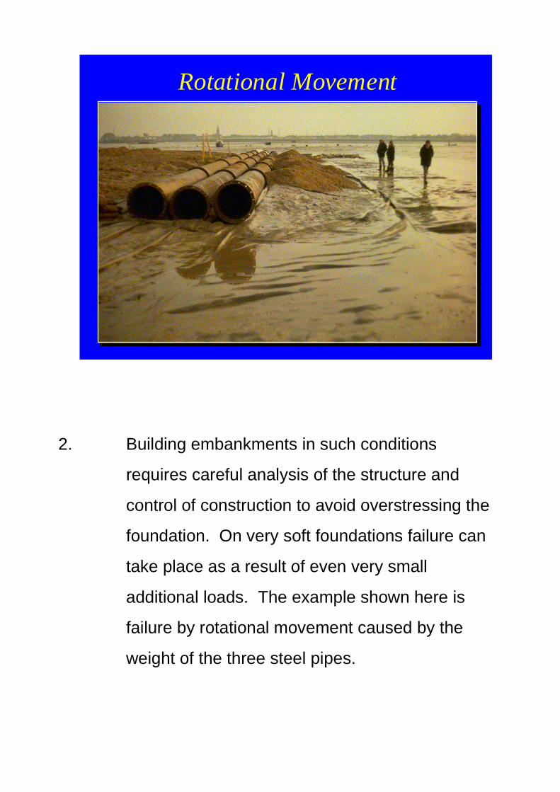
2. Building embankments in such conditions
requires careful analysis of the structure and
control of construction to avoid overstressing the
foundation. On very soft foundations failure can
take place as a result of even very small
additional loads. The example shown here is
failure by rotational movement caused by the
weight of the three steel pipes.
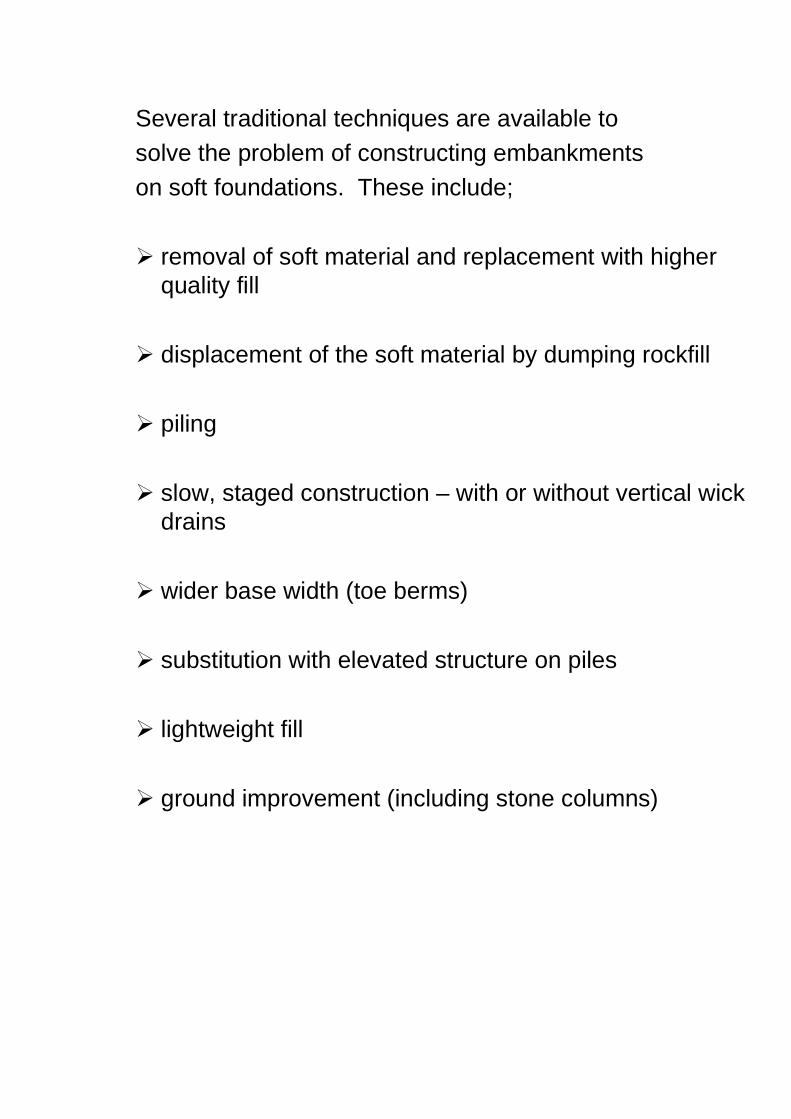
Several traditional techniques are available tosolve the problem of constructing embankmentson soft foundations. These include;
� removal of soft material and replacement with higherquality fill
� displacement of the soft material by dumping rockfill
� piling
� slow, staged construction – with or without vertical wickdrains
� wider base width (toe berms)
� substitution with elevated structure on piles
� lightweight fill
� ground improvement (including stone columns)

3. Another view of geosynthetic in use
In many cases geosynthetics can provide a structurally sound solution at a lower cost and faster than traditional methods.
In the general case, a failure surface is likely to form
through the soft foundation soil extending upwards through the embankment fill material. This leads to
lateral movement of the foundation below the toe of the embankment plus part of the embankment itself. The
purpose of the geosynthetic in its simplest form is to tie the potentially failing area back into the stable zone behind the failure surface.
Basal Reinforcement usingGeogrids

Here, high tensile strength is required to maintainstability and prevent failure.
Gradual settlement of an embankment (withoutover-stressing leading to failure) is evidence ofconsolidation of the foundation soil as water is
squeezed out and the soil increases in density.At the same time the shear strength of the
foundation increases and this often means thatthe tensile force required from the geosynthetic
reduces with time and may become zero after 5to 10 years.
b) Analysis & Design
4.
Analysis is carried out using standard geotechnicalmethods and stability is achieved by incorporation ofthe tensile force provided by the geosynthetic.
Foundation soil parameters are normally considered
in total stress terms since this is considered to bemore appropriate and also conservative.

Several computer programs have been developed to
analyse such structures and allow a layout of suitablegeosynthetics to be determined (1)(2)(3)(4)(5)(6).Other methods are detailed in British Standard Code
of Practice BS 8006 (7) and in the FHWA Course onDesigning with Geosynthetics, Chapter 7.0 (8).
Three main failure mechanisms should be
considered.
Rotational Stability
ReinforcementReinforcement
Soft Clay FoundationSoft Clay Foundation
EmbankmentEmbankment fill
Reinforcement tensionReinforcement tensiondevelops as a vector ofdevelops as a vector ofthese forcesthese forces
TrTr
BewareBeware ofofditches in thisditches in thisarea!!!area!!!
Failure can be deep seatedFailure can be deep seatedor shallow depending onor shallow depending onembankment / foundationembankment / foundationgeometrygeometry

a) Rotational Stability
The most common form of analysis for foundation
failures is to use a modified version of the SimplifiedBishop Method for circular slip surfaces.
The basic equation is modified by adding into the
equation the force available from the reinforcement.This force can either be the horizontal component(a conservative approach) or the tangential
component.
Using a partial factor method such as that set out inBritish Standard 8006 there will be no minimum
required Factor of Safety, the requirement is simplyfor all the factored forces to be in equilibrium.
The locus of required force across the base can bedetermined to predict the maximum required force
from the reinforcement, TD.
Other methods can be used for different shapes offailure surface with added mathematical complexity.
Circular slip surfaces have been shown by trials andmathematical modeling (FEM and FDM) to be a
good approximation to real and predicted behaviour.

Reinforcement may continue across the full width of
embankment or may be concentrated in areashaving the lowest safety factors determined by the
analysis. External conditions must always beconsidered such as the need to excavate near thetoe of the embankment for ditches, drainage pipes
or other service trenches.
5.
b) Lateral Sliding
Resistance to lateral sliding across the surfaceof the of the reinforcement can be determined by
calculating the active fill driving force, this mustbe resisted by the reinforcement with stresses
transferred by friction between the soil and thereinforcement in direct shear.

Values of geosynthetic/soil interface friction should be
obtained from testing which uses the actual geosyntheticand actual soil to be used on the project. Suitable tests
are described in British Standard 6906 Part 8 (9) or ASTMD5321 (10).
Lateral Sliding
ReinforcementReinforcement
Soft Clay FoundationSoft Clay Foundation
Embankment fillEmbankment fill
Reinforcement tensionReinforcement tensiondevelops in the plane of thedevelops in the plane of thereinforcementreinforcement
TrTr
HorizontalHorizontalmovement of fill,movement of fill,driven by activedriven by activewedgewedge

6.
c) Bearing Capacity
i) Where the thickness of soft foundation soil is greaterthan the embankment base width then a standardbearing capacity analysis should be carried out.Although obvious, it is worth pointing out that thepresence of reinforcement within the embankment willnot prevent a bearing capacity failure of an overstressedfoundation.
Foundation Extrusion
Soft Clay FoundationSoft Clay Foundation
EmbankmentEmbankment fillLateral extrusion ofLateral extrusion offoundations due tofoundations due tosettlement of fillsettlement of fill
The solution to this mode of failure is toThe solution to this mode of failure is toreduce the settlement by making thereduce the settlement by making thebase stiffer (Geocell mattress)base stiffer (Geocell mattress)
ReinforcementReinforcement
ii) Where the layer of soft soil is less than theembankment base width failure manifests itself inextrusion of foundation material at the toe of theembankment and settlement of the embankment fill.

7.
Analysis requires solution of the forces and resistance
acting in the system. The need is to stiffen the base ofthe embankment using either multi-layer geosynthetics or
a geocell mattress (usually 1 metre deep).
The analysis of Geocell mattresses is usually carried out
using a `slip line field’, based on bearing capacity theory.The tensile forces in the mattress are determined from a
method which looks at the stresses acting on the base ofthe mattress.
Basal Reinforcement : Geocell

7a. Slip Line Field
A Geocell mattress is a particularly good solution wherehigh embankments are to be built on relatively thin very
soft strata. A ratio of embankment width to depth of softsoil greater than 4 is ideal.

8. General
In all cases both ultimate limit state and serviceabilityrequirements need to be considered.
A number of computer programs are available to permit the
design of geosynthetic reinforced embankments on softfoundations.
In many cases a Modified Bishop Method is used to analyse
circular slip surfaces in an embankment containing basallayers of reinforcement.
Serviceability Limit States
• The serviceability limit states are related topermissible movements, settlement of thefill surface
Soft Clay FoundationSoft Clay Foundation
Embankment fillEmbankment fill
ReinforcementReinforcement
SettlementSettlement

Evidence exists to suggest that a stiff reinforcement may alter
the shape of a failure surface by driving it deeper into thefoundation soil (11). Since foundation soils normally show
increasing strength with depth this would always increase thestability and is therefore an additional safety factor usually
ignored in design.
9.
Equally, computer programs can consider non-circular failuresurfaces such as, in this case, lateral sliding.

Embankments over voids
In special cases the foundation may be subject to collapse asin the case of construction over abandoned mineworkings or
natural voids which are capable of migrating to the surface.

10.
View of Ripon Bypass (Paralink)
Embankments over voids
In special cases the foundation may be subject tocollapse as in the case of construction overabandoned mineworkings or natural voids whichare capable of migrating to the surface.
Here the geosynthetic may be designed to performa short-term or long-term function.

In the short-term case significant deformation takesplace but collapse is prevented for several hours or
days allowing all traffic or people to be removed fromthe area and a permanent solution to be devised.
In the long-term case the geosynthetic is designed tomaintain the serviceability of the embankment over thedesign life of the project.
11. Load Transfer Platforms
In situations where settlement is unacceptable, embankments are often supported on concrete piles or lime columns.
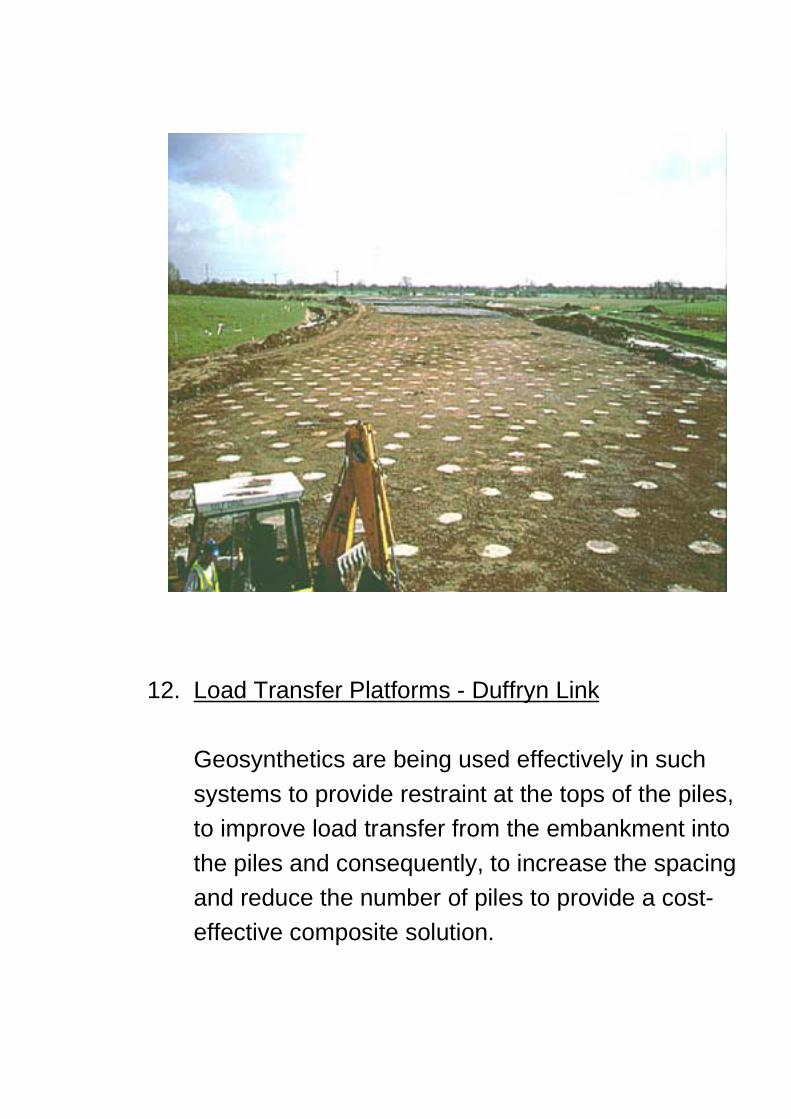
12. Load Transfer Platforms - Duffryn Link
Geosynthetics are being used effectively in such
systems to provide restraint at the tops of the piles, to improve load transfer from the embankment into
the piles and consequently, to increase the spacing and reduce the number of piles to provide a cost- effective composite solution.

c) Requirements from geosynthetics
13. View of Geosynthetic
Geosynthetics used in embankment applications
have several in-use performance requirements. They must have;
a) high tensile strength in at least the longitudinal direction,
Basal Reinforcement using Geotextiles

b) the ability to maintain high load carrying capacity
for several years,
c) the ability to transfer load effectively from the soil into the geosynthetic either by interlock or surface
friction,
d) high resistance to installation damage,
e) durability against UV attack and against chemical
and biological attack in the soil.
d) Types of geosynthetics
14. Woven or knitted geotextiles

Several types of geosynthetics are used in suchapplications.
For cases where the design requires very high tensilestrength woven or knitted geotextiles are available, mostoften manufactured from polyester with ultimate tensilestrengths in the range up to 1250kN/metre width.
15. Extruded geogrids
Extruded geogrids are used in many applications where ultra high strength is not required and where the special features of geogrids are especially suitable such as in the construction of geocell foundation mattresses or to enhance arching in load transfer platforms.

16. Woven or welded geogrids
Coated, woven or welded geogrids have certain of the characteristics of geotextiles and of geogrids in
that they can have open apertures, enhanced durability due to coating of the fine, load carrying,
fibres and also very high tensile strength up to 1250kN/metre width.

d) Examples/Case Studies
17. Case Studies
a) High Strength geotextiles (12)
Lok Ma Chao Highway, Hong Kong
18.
This highway connecting Hong Kong to Shanzen wasbuilt in 1986/87 and involved embankment
construction over swamps and fish ponds. Foundationsoils consisted of 10m depth of soft clay with shearstrength as low as 3kN/m2.

A 400kN/m woven geotextile was used to reinforce thebase of the embankment and vertical wick drains were
installed to accelerate consolidation.
19.
Use of the geotextile reinforcement avoided the long termperiod required for preloading techniques and also the
high cost of an excavation and replacement solution.

20.
The opportunity was taken to monitor five sections of the
2km road with strain gauges on the geotextile andsettlement indicators, piezometers and inchmometers inthe soil.

22. b) Load Transfer Platform Toll Plaza, Second Severn Crossing, UK (13)
23. 1042/22
The soils cross section shows extensive deposits ofestuarine mud underlain by peat.

24. 1042/29
Vibro concrete columns (VCC’s) are placed using a vibroreplacement rig with concrete pumped in as the probe iswithdrawn to form a column of concrete. The installationtechnique creates a domed top to form a type of pile cap.

25. 1042/7
The purpose of the geosynthetic is to transferembankment loads into the pile caps. This is achievedby laying two or more layers of relatively lightweightgeogrids within a granular layer over the piles. Full scaletesting has shown very significant load transfer with verylow imposed loads on the area between VCC’s.

26. 1042/1
Construction can proceed swiftly with placing of thegeogrid and granular layer keeping pace with VCCinstallation. Embankment fill follows as soon assufficient strength has been achieved in the VCC’s.

27. 1042/51
Aerial view of the Toll Plaza area on the soft estuarinemud.
28. 1042/52
Aerial view of complete bridge

c) Geocell Foundation Mattress
WENT Landfill Access Road, Hong Kong (14)
29. 782/2
Part of the 5km access road to the WENT landfill crossesan alluvial plain on embankment up to 10m high.
Over part of its length the embankment is underlain bysoft clay deposits with undrained shear strengths in the
range 10 to 25 kPa to depths of around 6 metres.

30. 782/1
The chosen solution was to install vertical band drainsbeneath the embankment and then to construct ageocell foundation mattress as the foundation to theembankment.
A geocell mattress is formed by laying a biaxial geogridbase and connecting to it 1 metre wide strips of uniaxialgeogrid laid across the width of the embankment.

31. 782/5
The transverse geogrids are rotated into the verticalposition and a triangular honeycomb structure is formedby interlacing another uniaxial geogrid alternately with thetransverse grids on either side.

32. 782/4
A section of completed geocells is rapidly constructedand erection easily outpaces filling of the cells withgranular material.

33. 782/47
Filling initially takes place from the edge but once an areais filled then further stone deliveries and the fillingequipment operate on top of the filled portion.
Conclusions from instrumentation of the project showedthat extensions in the mattress were 1% or less and thatthe geocell foundation mattress behaved as a relativelystiff foundation to the embankment as expected.

REFERENCES
(1) Computer Programme, Slope, Geosolve, 69 Rodenhurst
Road, London, SW4 8AE, England
(2) Computer Programme, Stable, M Z Associates Ltd, 1
High Street, Little Eversden, Cambridge, CB3 7HE, England
(3) Computer Programme, ReSlope (3.0), Adama
Engineering Inc, 33 The Horseshoe, Covered Bridge Farms, Newark, Delaware A711, USA,
(4) Computer Programme, PCSTABL6, Purdue University,
School of Engineering, Grisson Hall, West Lafayette, Indiana 47909, USA, Tel 317 494 9753
(5) Computer Programme, IDAT, IDAT, Dieburger Strasse
80, D-64287, Darmstradt, Germany, [email protected]
(6) Computer Programme, GGU, Gesellschaft für Grundbau und Umwelttechnik GmbH, Am Hafen 22, 38112 Braunschweig, Germany, www.ggu.de

REFERENCES
(7) British Standards Institution BS8006, BSI, 389 Chiswick High Road, London, W4 4AL, Tel 0208 996 9000, www.bsi.org.uk
(8) Holtz R.D, Christopher B.R, Berg R.R (1998?), Geosynthetic Design and Construction Guidelines. National Highway Institute, Federal Highway Administration, McLean, Virginia
(9) British Standards Institution BS6906, BSI, 389 Chiswick High Road, London, W4 4AL, Tel 0208 996 9000, www.bsi.org.uk
(10) ASTM D5321, Test Method for Determining the Coefficient of Soil and Geosynthetic or Geosynthetic or Geosynthetic Friction by the Direct Shear Method. American Society for Testing and Materials, 100 Barr Harbor Drive, West Conshohochen, PA 19428 – 2959, USA, Tel 610 832 9500, Fax 610 832 9635, www.astm.org
(11) Williams D, Reinforced Embankment at the Great Yarmouth Bypass, C H Dobbie & Partners, England Williams D. & Sanders R.L, Design of Reinforced Embankment for Great Yarmouth Bypass, C H Dobbie & Partners, England

REFERENCES
(12) Risseeuw P & Voskamp W, Geotextile and Vertical
Drains for Deep Foundation Improvement Lok Ma Chao,
Hong Kong”. Geosynthetics Case Histories.
(13) Bell A.L (Keller Ltd, Coventry), Jenner C.G (Netlon Ltd, Blackburn), Maddison J.D (Halcrow-Seee JV, Cardiff) &
Vignoles J (Laing GTM JV, Bristol) (1994), Embankment Support using Geogrids with Vibro Concrete Columns on
the Second Severn Crossing Toll Plaza. Paper available from Netlon Ltd, Blackburn
(14) Cowland J.W & Wong S.C.K (1992), Performance of a Road Embankment over Soft Clay Supported on a Geocell Mattress Foundation on Went Landfill, Hong
Kong available from Civil Engineering Department, Highways Department, Hong Kong Government, 101
Princess Margaret Road, Kowloon, Hong Kong