a theoretical investigation of composite … theoretical investigation of composite overwrapped...
TRANSCRIPT
NASA/TM—2009-215684
A Theoretical Investigation of CompositeOverwrapped Pressure Vessel (COPV)Mechanics Applied to NASA Full Scale Tests
John C. TheskenOhio Aerospace Institute, Brook Park, Ohio
Pappu L.N. MurthyGlenn Research Center, Cleveland, Ohio
S.L. PhoenixCornell University, Ithaca, New York
N. GreeneNational Aeronautics and Space Administration, White Sands Test Facility, Las Cruces, New Mexico
Joseph L. PalkoConnecticut Reserve Technologies, Inc., Cleveland, Ohio
Jeffrey Eldridge and James SutterGlenn Research Center, Cleveland, Ohio
R. Saulsberry and H. BeesonNational Aeronautics and Space Administration, White Sands Test Facility, Las Cruces, New Mexico
September 2009
https://ntrs.nasa.gov/search.jsp?R=20090037028 2018-05-12T17:40:31+00:00Z

NASA STI Program . . . in Profile
Since its founding, NASA has been dedicated to theadvancement of aeronautics and space science. TheNASA Scientific and Technical Information (STI)program plays a key part in helping NASA maintainthis important role.
The NASA STI Program operates under the auspicesof the Agency Chief Information Officer. It collects,organizes, provides for archiving, and disseminatesNASA’s STI. The NASA STI program provides accessto the NASA Aeronautics and Space Database andits public interface, the NASA Technical ReportsServer, thus providing one of the largest collectionsof aeronautical and space science STI in the world.Results are published in both non-NASA channelsand by NASA in the NASA STI Report Series, whichincludes the following report types:
TECHNICAL PUBLICATION. Reports ofcompleted research or a major significant phaseof research that present the results of NASAprograms and include extensive data or theoreticalanalysis. Includes compilations of significantscientific and technical data and informationdeemed to be of continuing reference value.NASA counterpart of peer-reviewed formalprofessional papers but has less stringentlimitations on manuscript length and extent ofgraphic presentations.
• TECHNICAL MEMORANDUM. Scientificand technical findings that are preliminary orof specialized interest, e.g., quick releasereports, working papers, and bibliographies thatcontain minimal annotation. Does not containextensive analysis.
• CONTRACTOR REPORT. Scientific andtechnical findings by NASA-sponsoredcontractors and grantees.
• CONFERENCE PUBLICATION. Collectedpapers from scientific and technicalconferences, symposia, seminars, or othermeetings sponsored or cosponsored by NASA.
• SPECIAL PUBLICATION. Scientific,technical, or historical information fromNASA programs, projects, and missions, oftenconcerned with subjects having substantialpublic interest.
• TECHNICAL TRANSLATION. English-language translations of foreign scientific andtechnical material pertinent to NASA’s mission.
Specialized services also include creating customthesauri, building customized databases, organizingand publishing research results.
For more information about the NASA STIprogram, see the following:
• Access the NASA STI program home page athttp://www.sti.nasa.gov
• E-mail your question via the Internet to help@
sti.nasa.gov
• Fax your question to the NASA STI Help Deskat 443–757–5803
• Telephone the NASA STI Help Desk at443–757–5802
• Write to:NASA Center for AeroSpace Information (CASI)
7115 Standard DriveHanover, MD 21076–1320

NASA/TM—2009-215684
A Theoretical Investigation of CompositeOverwrapped Pressure Vessel (COPV)Mechanics Applied to NASA Full Scale Tests
John C. TheskenOhio Aerospace Institute, Brook Park, Ohio
Pappu L.N. MurthyGlenn Research Center, Cleveland, Ohio
S.L. PhoenixCornell University, Ithaca, New York
N. GreeneNational Aeronautics and Space Administration, White Sands Test Facility, Las Cruces, New Mexico
Joseph L. PalkoConnecticut Reserve Technologies, Inc., Cleveland, Ohio
Jeffrey Eldridge and James SutterGlenn Research Center, Cleveland, Ohio
R. Saulsberry and H. BeesonNational Aeronautics and Space Administration, White Sands Test Facility, Las Cruces, New Mexico
National Aeronautics andSpace Administration
Glenn Research CenterCleveland, Ohio 44135
September 2009
This report contains preliminary Þ ndings,subject to revision as analysis proceeds.
Level of Review: This material has been technically reviewed by technical management.
Available from
NASA Center for Aerospace Information National Technical Information Service7115 Standard Drive
5285 Port Royal RoadHanover, MD 21076–1320
SpringÞ eld, VA 22161
Available electronically at http://gltrs.grc.nasa.gov
A Theoretical Investigation of Composite Overwrapped PressureVessel (COPV) Mechanics Applied to NASA Full Scale Tests
John C. TheskenOhio Aerospace InstituteBrook Park, Ohio 44142
Pappu L.N. MurthyNational Aeronautics and Space Administration
Glenn Research CenterCleveland, Oho 44135
S.L. PhoenixCornell University
Ithaca, New York 14853
N. GreeneNational Aeronautics and Space Administration
White Sands Test FacilityLas Cruces, New Mexico 88004
Joseph L. PalkoConnecticut Reserve Technologies, Inc.
Cleveland, Ohio 44136
Jeffrey Eldridge and James SutterNational Aeronautics and Space Administration
Glenn Research CenterCleveland, Oho 44135
R. Saulsberry and H. BeesonNational Aeronautics and Space Administration
White Sands Test FacilityLas Cruces, New Mexico 88004
NASA/TM—2009-215684
ABSTRACT
A theoretical investigation of the factors controlling the stress rupture life of theNational Aeronautics and Space Agency’s (NASA) composite overwrapped pressurevessels (COPVs) continues. Kevlar® fiber overwrapped tanks are of particularconcern due to their long usage and the poorly understood stress rupture process inKevlar® filaments. Existing long term data show that the rupture process is a functionof stress, temperature and time. However due to the presence of a load sharing liner,the manufacturing induced residual stresses and the complex mechanical response, thestate of actual fiber stress in flight hardware and test articles is not clearly known.This paper is a companion to the experimental investigation reported in [1] anddevelops a theoretical framework necessary to design full-scale pathfinderexperiments and accurately interpret the experimentally observed deformation andfailure mechanisms leading up to static burst in COPVs. The fundamental mechanicalresponse of COPVs is described using linear elasticity and thin shell theory anddiscussed in comparison to existing experimental observations. These comparisonsreveal discrepancies between physical data and the current analytical results andsuggest that the vessel’s residual stress state and the spatial stress distribution as afunction of pressure may be completely different from predictions based upon existinglinear elastic analyses. The 3D elasticity of transversely isotropic spherical shellsdemonstrates that an overly compliant transverse stiffness relative to membranestiffness can account for some of this by shifting a thin shell problem well into therealm of thick shell response. The use of calibration procedures are demonstrated ascalibrated thin shell model results and finite element results are shown to be in goodagreement with the experimental results. The successes reported here have lead tocontinuing work with full scale testing of larger NASA COPV hardware.
NASA/TM—2009-215684 2
INTRODUCTION
The advent of high performance aramid and carbon fiber has enabled the evolutionof filament wound pressure vessels capable of extreme energy storage capacity perunit mass, PBV/W, where PBV is the product of burst pressure and vessel volume andW is the weight or mass of the vessel. Starting in the 1960’s and 70’s, this potentialwas recognized by Johns and Kaufman[2], Lark [3,4] and Faddoul [5] at the NASALewis Research Center as a number of design and manufacturing studies began toinvestigate the technical feasibility of filament wound pressure vessels for space flight.Landes [6] and Ecord [7] published early work describing this technology withreported weight savings of 25 to 30% over comparable all metallic spherical vessels[8]. Today composite overwrapped pressure vessels (COPVs) are essential tonumerous NASA power and environmental systems. The majority of older vesseloverwraps are made of Kevlar®-49/Epoxy Composites while the newer vessels haveCarbon/Epoxy overwraps.
The Kevlar®-49 fiber overwrapped tanks are of particular concern due to their longusage and the poorly understood stress rupture process in Kevlar® filaments. Thesetanks were designed and developed in the late 1970’s and most of them have been inservice since delivery in the 1980’s. Stress rupture in Kevlar®-49 gives noforewarning so Schmidt and Ecord [9], at the Johnson Space Center, initiated anaccelerated stress rupture test program to lead service hardware in actual time atpressure. The occurrence of burst events in that test program motivated the NASAEngineering and Safety Center to establish an Independent Technical Assessment ofthe COPVs used in NASA applications.
While existing long term data show that the stress rupture process in Kevlar® fiberis a function of fiber stress, temperature and time, it is questionable whether thestandard stress – rupture life representation of data may be used by itself for future lifeextension of NASA COPVs. A substantial contributor to the uncertainty is thepresence of load sharing liners and complex manufacturing procedures such that thestate of actual fiber stress in flight hardware and sub-scale test articles is not clearlyknown. As is the case with many ageing aerospace systems, the objective to extendflight certification for this hardware would benefit substantially from two concertedefforts:
1.) Improve the understanding of the component’s complex mechanical response,state of stress and deformation.
2.) Improve the fidelity of the stress rupture lifing methods, data base and use ofthe appropriate reliability framework for the stress rupture threat.
Contributing to the first effort, this paper and a companion paper by Greene et al[1] deal with the theoretical and experimental investigation of the mechanical responseof COPVs. The primary focus here and in [1] is the development of a full scalepathfinder test program for vessels in NASA systems. The second effort benefits froma great body of work in the statistical strength theory of fibrous composites and thestress rupture phenomenon that has been developed since the first vessels enteredservice [10]. The potential improvements for stress rupture lifing methods arehighlighted in papers in these proceedings by Phoenix et al [1 1] and Ledesma-Grimeset al [ 12]. The former [ 11 ] details efforts to enhance the fidelity of the data through theprovision of a sound framework for life extension and the latter [12] describes lessonslearned in generating stress rupture data. A final paper by Saulsberry et al [13],
NASA/TM—2009-215684 3
concerning NDE methods for COPVs, bridges the two efforts as specializedexperimental methods are needed to enhance our ability to understand the mechanicalresponse of COPVs and also offer potential benefits in structural healthmonitoring/life management activities.
The importance of accurate mechanical response predictions to stress rupture lifingis apparent in how stress rupture life prediction is accomplished. Programs to generatestress rupture data typically comprise a series of short term load to failure tests todetermine an ‘ultimate strength” for a coupon or test article. This is combined with agroup of long term tests where coupons/test articles are held at some constant loaduntil failure occurs. Results of the ultimate strength and long term tests are plottedwith the load parameter as a function of time to failure. In addition to Schmidt andEcords [9] fleet leader test program, the most exhaustive source of available data forthe development of Kevlar® fiber lifing models has been the well known LawrenceLivermore National Laboratory (LLNL) data (see e.g. Toland et al [14]).
While the mechanisms of Kevlar® stress rupture remain unclear, Phoenix and Wu[15] show that it has a functional dependency on stress, temperature and time that maybe fundamentally linked to the failure process at the fiber bundle level. Scaling thisprocess from small individual filaments to a full scale COPV involves consideration ofWeibull size effects [15] in the failure process and understanding of the structuralcharacteristics of each COPV. An excellent overview of statistical strength theory forfibrous composites relevant to stress rupture lifing may be found in Phoenix andBeyerlein [10]. Historically, a ratio of the operating state parameter to the ultimatestate parameter has been used to scale life data to dissimilar structures. Liftingparameters such as pressure ratio, stress ratio and percent of ultimate strength areamong the common terms used for this comparison. It is important that suchparameters be based on the state of the fiber at burst pressure of that vessel. As will beseen, it is difficult to accurately characterize the fiber state at operating and burstpressure levels, in test articles and flight hardware, alike.
An introduction to the mechanical complexities may be found in a review of earlyCOPV design considerations given by Lark [3]; several key points are listed here. It isinteresting to note that early designs of high performance COPVs sought to achieveoperation fiber stress levels at 60 to 70% of ultimate strength. At these stress levels,strains in the composite exceed the limit for matrix cracking and crazing. As a result,liners were required to achieve viable leak free structures. Early on, elastomers andthin metallic liners were studied carefully due to their potential to achieve the greatestpossible energy storage capacity. However, the elastomers examined in early trialswere not viable in cryogenic applications and in high pressure gas uses due to crackingand blistering. Thin metallic liners yield during pressurization and must be bonded tothe composite overwrap to prevent liner buckling or wrinkling during unloadingphases. Lark[3] reported difficulties in achieving leak free liner designs with goodfatigue durability in the early attempts to develop COPVs with thin metallic liners. Atthat time it was suggested that an interim approach to achieve a measure of theimproved performance capacity would be to use load bearing liners. This concept wasoriginally suggested by Johns and Kaufman [2] in 1966 and had matured more quicklythan the thin metallic liner approach. It is one of the earliest references to the loadsharing liner concept which is in use on many NASA systems today. It should benoted that Lark makes a clear distinction between load bearing/load sharing linerdesigns and the so called thin metallic liner designs. However, the implication that the
NASA/TM—2009-215684 4
load carrying contribution of thin metallic liners is insignificant can lead to falseconclusions when deriving the state of stress of such vessels. All of the test articlevessels, used in the above named stress rupture programs [9,14], make use of thoserelatively thin metallic liners with low yield strength. It should be noted that the earlypublished data reduction did not correct for the influence of these thin liners which canintroduce significant effects which will be pointed out here and in the papers byPhoenix et al [11] and Grimes-Ledesma et al [12].
Load bearing liners are designed to carry one-third to one-half of the internalpressure load elastically. The remainder of the load is carried by the compositeoverwrap. After the overwrap is cured in place on the liner an initial proof or sizingpressure is applied which takes the liner beyond its biaxial tensile yield limit andinduces a permanent interference pressure between the liner and the overwrap. Duringunloading the liner transitions from a state of biaxial tension to biaxial compressionwhile the overwrap filaments remain in tension even at zero applied pressure. Theselocked in residual stresses are superimposed on to the elastic load share of the internalpressure that each element carries. Subsequent operation loads beneath the proof orsizing pressure are carried elastically by both the liner and the overwrap. Whileanalysis indicates that residual stresses contribute over 15% of the composite stress atoperating pressures, these values have not been accurately measured and monitoredovertime. Recently this important contribution to the fiber stress state was measuredusing Raman Spectroscopy and fiduciary markers and these results are reported wereapplicable.
First the fundamental mechanical response of spherical composite overwrappedpressure vessels is described using thin shell theory. Approaches accounting for theinfluence of elastic-plastic liners and degraded/creeping overwrap properties arereviewed. Graphical representation methods are presented to illustrate the non-linearrelationship of applied pressure to Kevlar® fiber stress/strain during manufacturing,operations and burst loadings. These methods may be applied to interpret experimentalmeasurements and to calibrate the model parameters. Examples are givendemonstrating the correct calibration of fiber stress as a function of pressure and somecomparisons are made to available finite element analyses. Preliminary analysis of thepathfinder tests conducted by the NASA White Sands Test Facility (WSTF)[1] ispresented for discussion.
While all of these approaches are of remarkable utility it is important to exploretheir limitations. Continuing work with the current mechanical analysis finds that it isnot fully validated by existing experimental deformation data. Until recently, the stateof residual stress at zero pressure remained unsubstantiated by experimentalmeasurement. Moreover, records of internal and external vessel deformation indicatean increased compliance that may not be accurately represented by linear elasticanalysis. In addition to the pathfinder vessel testing at WSTF [1], preliminary resultsof experiments to measure residual stresses are reported. This has pointed to newavenues of investigation exploring the ramifications of non-linear through thicknesscompressibility and the influence of highly localized plastic instabilities in the liner.
NASA/TM—2009-215684 5
COPV MECHANICS
Theory of Thin Shells
The theory of thin shells is useful to develop a theoretical framework to design andanalyze the full scale pathfinder experiments. The following describes the nominalmechanical response of a spherical bi-material pressure vessel. Actual COPVstructures will exhibit a non-uniform distribution of stresses and deformation owing toa number of factors. These include the nuances of liner geometry and its interactionwith the overwrap winding pattern, the relative stiffness of the liner to the overwrap,the liner-overwrap interface slip characteristics and the presence of incompatiblecurvature changes. In areas where the liner thickness is uniform, the overwrap may beseen to act as an elastic foundation which cradles the liner. The polar boss areas ofliners are typically thickened and more rigid to support the port fixture. The localreinforcement acts as a stiff inclusion in the otherwise uniform metal membrane. Inthe elastic regime the boss support shields the overwrap from deforming uniformlywith the membrane regions of the shell. Liner yielding generally initiates at thetransition region between the boss and the membrane areas of the liner. Here plasticstrain concentrations are reported up to four times greater than nominal and these arestrongly dependent upon nuances of the liner overwrap frictional characteristics.Placed against the natural opening through the winding pattern, the boss acts as a stiffpunch against the overwrap once the transition has yielded. Early boss failures wereattributed to this stress concentration and new winding patterns increased the amountof fiber in the boss region to better support the boss fixture [3]. The nature of theelastic-plastic behavior of the liner is also prominent in determining the stress state ofthe overwrap. The liner’s plastic deformation and the presence of hardening will affectthe sizing process, zero pressure residual stresses, the liners fatigue durability and theoverwrap stress state at burst pressure.
With regard to the overwrap, complexity begins in the manufacturing phases withwinding parameters, consolidation and curing schedule. The degree of anisotropy ofthe overwrap is a factor; Gerstle’s [16] analysis may be used to demonstrate that highratios of in-plane to through thickness stiffness can transform a geometrically thinshell into a thick shell problem with significant through thickness gradients. It is alsoknown that filament wound structures can have different hereditary material responsestransverse to the fiber depending upon whether the stress is compressive or tensile(Thesken [17]). This non-linearity coupled with the known damage mechanismsassociated with the matrix dominated properties of polymer matrix composites makethe mechanical response of these COPVs a fundamentally complex problem.
With forethought to the objective of applying a correct lifing parameter for stressrupture, consider the notion of non-uniform fields in the overwrap. Assuming linearelasticity applies, the stress distribution in the composite overwrap may be defined as
σ^ ( x̂, P̂ ) = f ( x̂)σ^ (P̂ ) (1)
where f ( x̂) is a form function of the spherical coordinate vector x̂ and 6^n
(P̂ ) is
the nominal stress in the overwrap as a function of the composite’s pressure load shareP̂ . The value of the form function at a local maximum of stress is commonly known
as a stress concentration factor. Since the distribution function is decoupled from load,
NASA/TM—2009-215684 6

the formation of any stress ratio SR is found to be independent of the spatialdistribution function and simplifies to
oSR =
σc (x ,P
o
) = σco(Po)
σB (z, PB) σnB(PB (2 )c c c c
Since the Kevlar®-49 fibers are the dominant load carrying elements of thecomposite overwrap the notion that the overwrap is linear elastic is a valid firstapproximation. Additional information from a more detailed linear elastic analysiswould provide no further information for a lifing parameter determination. The stressratio would only change if the spatial distribution function became dependent uponload history i.e. a function ofPc . This is identical to saying that the stress
concentration factor at a local maximum is function of load Pc . This would be the case
if the composite behaved in a non-linear fashion due to material response or non-lineargeometrical effects. Equation (2) has been verified for a bonded liner model ofhardware in contracted finite element analysis performed by General Dynamics,Lincoln, Nebraska. Therefore, the use of thin shell theory is the preferred method forcharacterizing and appraising the performance capability of a COPV.
It should be noted that as presented, this approach to develop a stress ratio isconservative in that the non-linear effects that accelerate fiber stress are more likely tobe present at burst. Thus the denominator portion of the stress ratio may be larger thanwhat is predicted in the following thin shell analysis. In the following derivations, thelist of variable definitions given in Table I will be utilized for the spherical geometryshown in Figure 1.
TABLE I. VARIABLE DEFINITIONS
Pressure: P
Inner Wall Radii: RTangential Stress: σWall thickness: tElastic Modulus: EPoisson’s ratio: vBiaxial modulus: E*=E /(1-v)Fiber Volume Fraction: vf
Subscript and superscripts:l –liner; c- composite over wrap, f- fiber ;y- yield, u – ultimate tensile failure, i – interference load case,P- proof load case, B – burst load case, o –operating load case,n –nominal
NASA/TM—2009-215684 7

Kevlar/Epoxy _^ T\Composite Overwrap R 1
Metallic Liner
Figure 1. Typical spherical COPV geometry
LOAD EQUILIBRIUM REQUIREMENTS
Load equilibrium in the bi-material COPV vessels requires that the total appliedpressure be equal to the sum of the pressure carried by the individual components
P = Pl + Pc (3)
For thin shell analysis Rc ≈ Rl >> tc , tl , t f where typically the ratio of radii to
shell membrane thickness is greater than 10 for all vessels considered here andnominal membrane stress (dropping the n superscript) are
σl = P ⋅Rl
l 2 ⋅ tl (4)Rcσc = Pc ⋅
2 ⋅ tc
It is common to use mid-plane radii for membrane shell theory but comparisons tothe exact elasticity solution (see e.g. Roark [18]) show that this over predicts themaximum stress in the shell significantly. Using the inner wall radii in the familiarequations yields a membrane stress that agrees more closely with the maximum stresson the inner wall.
In the case of the quasi-isotropic composite overwrap for a sphere, this formulamay be re-written using the fundamental netting assumptions to determine the stress inthe fiber as
σf = νσc2
= σ^ ^tc = Pc ⋅ R̂ (5)f l f tf
From the design stand point it can be said that the ratio of ultimate fiber stress tocomposite pressure should always meet the following criteria to avoid failure:
σ uf> R̂ (6)
c f
Characteristics of the liner at yield are also of interest; clearly the pressure loadcarrying capability of the liner post yield is at least
Ply = σl
y ⋅ 2tl (7)Rl
and is only greater if the liner hardens. If the liner is perfectly plastic post yield thenthe liner load share is constant so the composite load share post liner yield is simply
Pc = P − Ply (8)
This relation suggests that the burst pressure to fail the overwrap could be predicted by
NASA/TM—2009-215684 8
PB = Pcu + Pl
y (9)
where the composite pressure uPc corresponds to the ultimate fiber stress 01.
Conversely the pressure carried by the composite at burst may be defined asPc
B = PB − Ply (10)
and the ratio c 1P, may be seen as a measure of the strength efficiency of the
composite overwrap design.
STRAIN CONTINUITY REQUIREMENTS
Continuity of strain and displacement in the liner and composite must be invokedto determine the elastic load sharing prior to proof or sizing of the vessel where thestress in the liner is less than the biaxial yield stress.
ε = εl = εc (11)
The biaxial strain for a spherical shell may be written as
ε = 6
= P R
"
(12)E 2tE
where the biaxial modulus is E " .Insertion into the equilibrium equation relates the applied pressure load to strain as
2t E" 2t E"P = P + P = R' + R ⋅ ε (13)
Rl c The definition of the individual shell stiffnesses as
_ 2 tlE1KlRl (14)
K = 2tc Ec
"
c R cwill be used here after.
The composite form of this parameter is the subject of some discussion as differentmethods have been used to approximate the effective biaxial stiffness. Some designreferences for the use quasi-isotropic laminate properties such that
EQI"E c QI
(15)(1 −νc )
Alternatively the netting analysis approach defines the biaxial modulus asE: = Ef ⋅ vf /2 (16)
The elastic load sharing parameters are defined as_ Kc = 1 _
Pc l P (Kl + KJ (Kl 1 Kc + 1) — (17)
= Kl = 1
=Pl /P (Kl + KJ (Kc I Kl + 1) (1 − β)
Note that either stiffness ratio (Kl 1 Kc ) or the elastic load sharing parameter β may
be used to full specify the designs elastic load share.
NASA/TM—2009-215684 9
PROOF-SIZING AND THE COMPLETE MECHANICAL RESPONSE
The manufacturing process sets final the crucial design parameters that must beevaluated for NASA COPVs. After curing of the composite overwrap, the vessels, issubjected to an autofrettage process or proof-sizing in which an elastic load sharingliner induces a permanent plastic deformation in the liner. After unloading an interfacepressure remains that is carried as a tensile preload in the composite and acompression preload in the liner. As the green vessel is loaded to the initial liner yieldpoint, the strains in the vessel are governed by the pressure strain equation (13) up to
the liner yield strain where E = Ec = EI . At liner yield, the applied pressure Py that
initiates liner yielding is related to the liner yield stress by equations (7) and (17) as
Ply__ 1 ( )Py (1 − β)18
For a vessel with a perfectly plastic liner that has yielded, the pressure carried by thecomposite is given by equation (10) so that the strain post yield is given by
P − Py
ε = εc = εl = K
l where ε > εly (19)c
Note that the strain in the vessel during increasing load is controlled by the overwrapwhich is assumed to remain elastic.
During the unload from proof the liner carries load elastically so the strain in theliner is determined by the total liner strain at proof less the elastic unload strain as
PP − Ply PP − P
εc = εl =− (K + (20)
Kc ( 1 K c)
The residual strain in the overwrap at zero pressure is
εR = PP − Ply −
PP (21)c Kc (Kl + Kc )
The interface pressure Pi which the composite and the liner carry identically is found
by
P = PP − Ply − βPP = (1 − β)PP − Pl
y (22)
Comparing the last two equations it is clear that the residual strain and interfacepressure are related by
Pi = KcεR (23)
All post autofrettage loadings must carry this pressure superimposed on the elasticload share. For the composite overwrap, this is an additive component inducing tensilestress at zero pressure and it is subtractive in the case of the liner inducingcompressive stress. Load sharing after proof is governed by the following relations for
P ≤ PP
Pc = βP + P = (P − PP W + (PP − Ply ) (24)
Pl = (1 − AP − P = (P − PP)(1 − β) + Ply
Deformation history referenced to the initial green state of the vessel is preserved inthe strain state of the overwrap so that
NASA/TM—2009-215684 10
CompositeStrain - Stress
1 ,
1 ,
1 ,
1
^ I
1 '
1 1 '
1 11 1 '
1 1
'R P B Rσc σc σc σl
LinerStrain - Stress
Burst
Proof---ε
pl_ __ l ___ Yield
-y---; ------ Residual1
σyl
ε = εc = K
(25)c
always gives the strain relative to the newly manufactured vessel. This will not be trueif the overwrap exhibits a hereditary response due time and temperature.
Graphical Interpretation and Model Calibration
Figure 2 gives a complete graphical interpretation of the mechanical response of aCOPV having a linear elastic overwrap and an elastic-perfectly plastic liner. In thisfigure, strain is given on the vertical axis and because of continuity, it is identical forthe COPV and the individual components. The corresponding pressures and stressesare given on the horizontal axis.
The as-cured vessel in the green state will undergo the sizing operation as depictedby the green lines for the COPV and the liner. Note on the left hand curve for COPVstrain – pressure behavior, that when the biaxial yield stress is achieved at a pressurecorresponding to Py, the strain – pressure curve changes slope. Here the changingstrain – pressure responses have a common value for strain so
P P — P
y = y ly
(26)( )l+ c c
providing a graphical way to determine β asy
KK) = 1 − PI (27)
(Kl + c y
Strain COPVStrain - Pressure
εBc----- -----------------
εcP
εly 1
r/s R ---- r - ---^---; --cc 1 1
Ply PY PP P B
Pressure Stress StressFigure 2. Strain– pressure/stress relationships based on continuity of strain for COPV vessel,
composite and liner respectively. Operational loads from P=0 to MEOP lie on the blue line for pressuresless than PP
NASA/TM—2009-215684 11
Also, note that the slope of the post yield curve is controlled by the stiffness of the
overwrap Kc so that it can be explicitly measured from experimental strain data. The
post yield line is offset so that its intercept with the pressure axis corresponds to the
pressure carried by the liner at yield Py . This intercept could be converted to the
biaxial yield stress of the liner if the liner geometry is known. Note that for a rigid-perfectly plastic liner there would be no strain in the vessel until the stress in the liner
reached the yield stress at the applied pressure Py at this intercept point. Thereafter,
deformations would be governed by the stiffness of the overwrap and follow the usual
post-yield slope. Once the overwrap stiffness Kc is known; it is possible to resolve
the stiffness of the liner from a measurement of the pre-yield slopes and solving forKl .
After the proof pressure is reached, the vessel undergoes elastic unloading.Inspection of the composite and liner strain – stress diagrams shows that bothmaterials exhibit linear elastic response in this regime. The liner has locked in apermanent plastic deformation that will not let it return to zero deformation. At zeroapplied pressure the composite exhibits a residual tensile stress and the liner exhibits aresidual compressive stress. Measurement of the overwrap strain at zero pressuredetermines residual stresses in the composite and the liner. Equilibrium between theliner and the composite requires that the membrane stress integrated over eachthickness must balance the interface pressure.
P = σ't c = εR Ec tc = −σR tl (28)
Additional constitutive information may be derived from the strain – pressurecurves if the geometry of the COPV is well described.
APPLICATION: STRESS RUPTURE TEST ARTICLE
An important example application of the above fundamental principles andgraphical analyses is the design appraisal of the test vessels used by Toland et al [14]which comprise the main body of Kevlar fiber stress rupture data. It should be notedthat these vessels were designed to operate with the liner above yield stress. In such acase, the pressure carried by the composite at any post yield load point and at burst isgiven by equations (9,10 and 11) and the fiber stress ratio at these load points is
σ o P R to ( / )f P oc f c= = (29)σf
PB (R / t f ) PcB
The stress rupture test data and the design curves have reported the Y-Axiscontrolled load parameter as a percentage of the composite/fiber strength at burstwhich is equivalent to multiplying equation (35) by 100% [14]. However, a closerexamination of the data indicated that the percentages, plotted, actually correspond tothe ratio of the total applied test pressure Po to the mean static burst pressure PB of thevessels. As stated in [10]:“Liner load sharing is nearly negligible. The 1100-0 Al yields at pressures between 24MPa (3.5 ksi) and 34.5 MPa (5 ksi). (Tlydroforming introduces some work hardening,however.) Classical shell formulas indicate that liner yield occurs at an approximate
NASA/TM—2009-215684 12
liner pressure of 1.25 MPa (181 psi). Strain gage data from virgin burst testsgraphically illustrate the liner yield.”
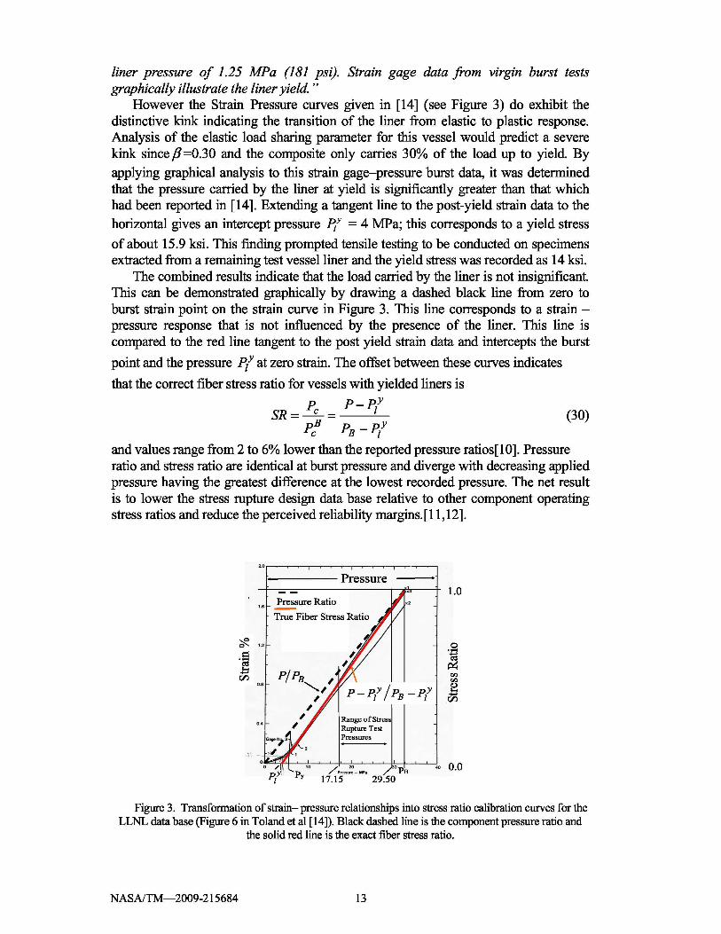
However the Strain –Pressure curves given in [14] (see Figure 3) do exhibit thedistinctive kink indicating the transition of the liner from elastic to plastic response.Analysis of the elastic load sharing parameter for this vessel would predict a severekink since β=0.30 and the composite only carries 30% of the load up to yield. Byapplying graphical analysis to this strain gage–pressure burst data, it was determinedthat the pressure carried by the liner at yield is significantly greater than that whichhad been reported in [14]. Extending a tangent line to the post-yield strain data to thehorizontal gives an intercept pressure P' = 4 MPa; this corresponds to a yield stress
of about 15.9 ksi. This finding prompted tensile testing to be conducted on specimensextracted from a remaining test vessel liner and the yield stress was recorded as 14 ksi.
The combined results indicate that the load carried by the liner is not insignificant.This can be demonstrated graphically by drawing a dashed black line from zero toburst strain point on the strain curve in Figure 3. This line corresponds to a strain –pressure response that is not influenced by the presence of the liner. This line iscompared to the red line tangent to the post yield strain data and intercepts the burst
point and the pressure Ply at zero strain. The offset between these curves indicates
that the correct fiber stress ratio for vessels with yielded liners is
Pc P − PlySR = B
= (30)Pc PB − Ply
and values range from 2 to 6% lower than the reported pressure ratios[10]. Pressureratio and stress ratio are identical at burst pressure and diverge with decreasing appliedpressure having the greatest difference at the lowest recorded pressure. The net resultis to lower the stress rupture design data base relative to other component operatingstress ratios and reduce the perceived reliability margins.[ 11,12].
Figure 3. Transformation of strain– pressure relationships into stress ratio calibration curves for theLLNL data base (Figure 6 in Toland et al [14]). Black dashed line is the component pressure ratio and
the solid red line is the exact fiber stress ratio.
NASA/TM—2009-215684 13
Vessel Fiber Stress Ratio for Load Sharing Liners
The LLNL vessels described above have significant metallic liners but due to alow yield stress, their contribution to load carrying remains constant in the rangewhere testing took place. Many NASA COPVs have significant liners that carry over30% of the load. A formulation of a stress ratio for lifing purposes from the thin shelltheory can be done using equation (29) where
P' = (Po − PP )β+(PP − Ply ) (31)
andB
P^ = PB − Ply (32)
Obviously, the pressure – fiber stress conversion term for the numerator anddenominator is the same, so the stress ratio is seen to be identical to the compositepressure ratio
σ1 = .Po =
(Po − PP )β+(PP − Ply) (33)B Bσf P^ PB − Ply
This result is similar to the finding concerning linear elastic stress concentrationfactors defined in equation (2).
DESIGN AND ANALYSIS OF FULL SCALE PATHFINDER TESTS:PRELIMINARY RESULTS
Background
It is clear from the simple mechanical evaluation of the stress rupture test articleused in [14] that correct assumptions about the mechanical response are required toproperly utilize the data for lifing purposes. The same is true for the application ofstress rupture lifing methods to actual flight hardware. In addition to operatingpressure Po and burst pressure, three parameters are observed to govern the stress ratioin the present formulation in (33): the elastic load sharing factor β, the pressure carriedby the liner at yieldPl
y , and the proof-sizing pressure PP. These three latter
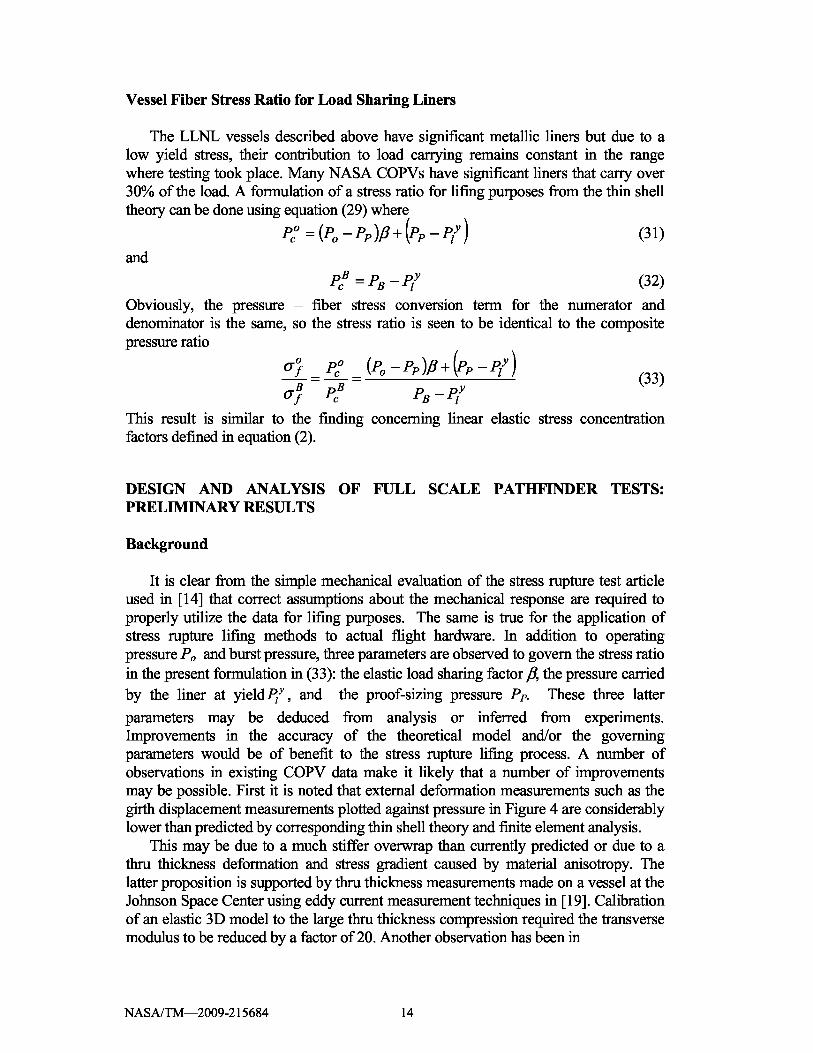
parameters may be deduced from analysis or inferred from experiments.Improvements in the accuracy of the theoretical model and/or the governingparameters would be of benefit to the stress rupture lifing process. A number ofobservations in existing COPV data make it likely that a number of improvementsmay be possible. First it is noted that external deformation measurements such as thegirth displacement measurements plotted against pressure in Figure 4 are considerablylower than predicted by corresponding thin shell theory and finite element analysis.
This may be due to a much stiffer overwrap than currently predicted or due to athru thickness deformation and stress gradient caused by material anisotropy. Thelatter proposition is supported by thru thickness measurements made on a vessel at theJohnson Space Center using eddy current measurement techniques in [19]. Calibrationof an elastic 3D model to the large thru thickness compression required the transversemodulus to be reduced by a factor of 20. Another observation has been in
NASA/TM—2009-215684 14
♦ Elastic Load Line
n Post Yield load line
f Measured data10n FEA Results
Linear (FEA Results)
1.0 PB — Linear (Post Yield load line) FEA
L MeasurementN Thin Shell/Plastic5NLIL
Thin Shell/Elastic
0.1 0.15 1. 0
Girth Displacement
Figure 4. Comparison of actual load-unload pressure – girth displacement data (red curve) to finiteelement results (cyan blue) and bi-linear thin shell theory (blue-pink curve). Actual vessel girth response
measurements appear much stiffer than existing analytical models.
manufacturing records of post-proof internal volume measurements that indicate largerthan predicted nominal residual strains. These findings together indicate the need for aseries of carefully designed and executed full scale vessel tests to accurately measurethe stresses and deformations in the COPVs.
Prior to testing actual hardware, a pathfinder test vessel was chosen to develop thefull scale experimental methods and examine the accuracy of the theoretical approach.The pathfinder test article was manufactured by ARDE Inc. and is similar in type tothe Kevlar® overwrapped vessel described in [20]. Table 2 provides nominal designparameters for this vessel. Only normalized or qualitative representations of data aregiven in the following; burst pressure and burst deformations are used as scale factors.
Based on design information provided the girth displacement as a function ofpressure has been given in Figure 4. A finite element analysis was conducted using an
TABLE 2 PATHFINDER VESSEL DESIGN PARAMETERS
Kl 1 K, 1.067 Ply I PB0.23
β 0.484PiPB
0.15
Kt = Kl + K, 0.917 PB /εΒ
NASA/TM—2009-215684 15

ABAQUS model and the resulting total strain distribution as a function of wrapnumber is given in Figure 5. It is compared to the corresponding thin shell modelresults for nominal strains in the vessel. The poor agreement between the finiteelement model and the thin shell theory is believed to be due to the nature of theresidual stress distribution in this vessel and the presence of radial gradients thruthickness.
The post sizing proof pressure for this vessel was 0.67 PB, but based on the roomtemperature yield stress for the liner and the liner-overwrap inner face pressure, thenew yield point may be determined from equation (22) to be 0.73 PB.
Analysis of Test Data
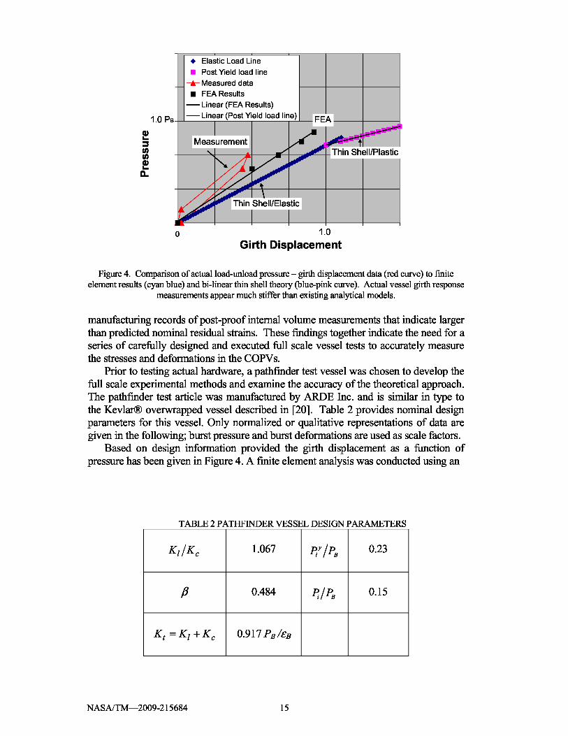
As described in [1], a series of static load cycles were conducted to 0.67 PB, 0.87PB, 0.93 PB and burst PB. Based on the room temperature yield stress for the liner andthe residual stress the predicted new yield point is 0.73 PB. Figure 8 shows the equatorstrain – pressure response for the first 0.87 PB cycle to yield the liner. The currentyield point (formerly proof pressure) occurs at 0.77 PB. The total stiffness for theelastic loading portion of the curve is 1.22 PB ZεΒ. The elastic load sharing factor forthe composite was found to be 0.514 using equation (27). The corresponding interfacepressure is given by equation (22) to be 0.15 PB. Here again, the actual vessel appearsto be 33% stiffer than what is predicted by thin shell theory and the currentconstitutive model. However, using the graphical analysis of Figure 6, the thin shellmodel may be calibrated. This has been done and the results are plotted against thestrain gage and Raman spectroscopy residual stress measurements for all load cases inFigure 7. The individual strain gages, residual stress measurements and finite elementresults are plotted as a function of wrap number.
Figure 7 shows strains in the boss area that are low rising to a maximum at wrap 4and then decreasing only slightly in route to the equator. The relatively homogeneousstrain in the membrane region between wrap 5 and 13 supports the notion of using athin shell model to simulate the observations, but the actual values using the vendorsupplied material data does not agree well with the experiments. The calibrated thinshell model using data from the load case of Figure 6 gives reasonable agreement forall load cases. The finite element results match the measured strain distribution quitewell except for the comparison to the zero pressure residual stresses measured byRaman spectroscopy. Raman spectroscopy measures elastic strain in the fiber as aspectral shift in scattered light. If the finite element results represent an initialcondition based on an elastic response, it is believed that the reduced elastic strainsmeasured by Raman spectroscopy reflect a stress relaxation process that has occurredover the life of the tank. The calibrated thin shell model results agree more closelywith the Raman spectroscopy.
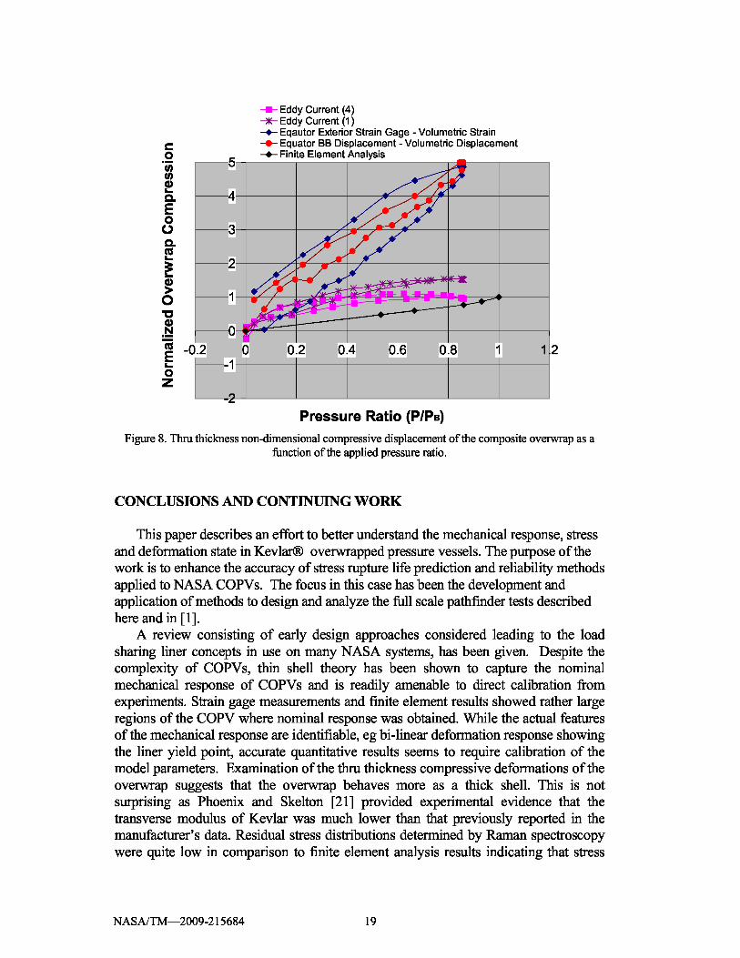
The eddy current measurements and the volumetric measurements were crucial tounderstanding the role of thru thickness gradients in the mechanical performance ofCOPVs. The volumetric deflections have been paired with external deformationmeasurements from strain gages and circumferential displacement gages to deducecompressive displacement, ∆ur , of the overwrap. Considering that the overwrap wallis bounded by concentric spherical surfaces, the geometric relationship used todetermine compressive displacement is given in the following equation.
NASA/TM—2009-215684 16

0 0.2 0.4 0.6 0.8 1
N+04I I I I I
N+04 I I I I I
N+04
I I I
N+04
I I I I
N+04
I I I I
I I I I I
It_-._t.+_ _ _ _--J_ _ _ _ _ _ _I_ _------•^ I I I
I I I I
I I I i t-I- - - - - - - - - - - -I I I I 'I
I I I I I
I I ^ I I.iN+04
0.0 PB Membrane Analysis • • 0.87 PB Membrane Analysis
N+03 Burst 1.0 PB Membrane Analysis t Burst 1.0 PB
• A 0.87 PB FNA )K Residual Stress 0.0PB
I I I I
N+03I I I I
N+03I I I I I
N+03 I I I I I
I I I I I
I I I I I
I I I I I
1 3 5 7 9 11 13Wrap Number
Figure 5. Comparison of thin shell model strains to finite element model from boss (wrap 1) to equator(wrap 13)
0.9
0.8
0.7cm 0.6
CO 0.5
.N 0.4CUE 0.30Z 0.2
0.1
0
Pressure Ratio (P/PB)
Figure 6. Normalized equator hoop strain as a function of pressure ratio on first cycle to 0.87 PB causingliner yielding at 0.767 PB.
NASA/TM—2009-215684 17
1.80E+04 n 0.67 PB at 0.2PB/min 0.87 PB at 0.2PB/min0.93 PB at 0.2PB/min x PB at 0.2PB/min
• Raman Spectroscopy 0.0 PB 0.0 PB Membrane Analysis1.60E+04
0.67 PBi Membrane Analysis • • 0.87 PB Membrane Analysis1.0 PB Membrane Analysis 1.0 PB FEA
1.40E+04- - 0.87 PB FEA 0.67 PB FEA
Residual Stress 0.0 PB
1.20E+04)IC
1.00E+04̂ ,------'^------ -+----it
8.00E+03 ------ `;
-R---
---------------r:nn.nn..nn.uuu,,,^_
6.00E+03
i
4.00E+03
2.00E+03
1 3 5 7 9 11 13Wrap Number
Figure 7. Strain gage measurements and Raman spectroscopy residual strain measurements as a functionof wrap number 1 (boss) to the 13 (equator) compared to the calibrated thin shell theory (horizontal
lines) and the finite element analysis.
∆u r = (εouter ⋅ router ) − (εinner ⋅ rinner ) (34)
where the inner strain is deduced from the vessel volume change and the outer strain isfrom the selected external measurement device.
The compressive displacements are given as a function of pressure ratio and arecompared to the eddy current sensor and the finite element results in Figure 8. All datahas been normalized relative to the compressive displacement at burst given by thefinite element analysis. Depending on sensor location, the displacements measured byeddy current are of the same order to about 1.5 times greater than those extracted fromthe finite element analysis. The analysis using volumetric deformation and surfacedeformations finds values up to 5 times larger than those in the finite element analysis.The discrepancy between the eddy current measurements is currently being evaluated.It is suspected that the bonded on eddy current gages may be lifting away from theouter surface as the load is applied. This would be true if edge cracks from the bondline propagated under the sensor as the Kevlar substrate is loaded. In any case, thefindings support the general proposition that thru thickness gradients may play a verysignificant role in determining the stress and strain state that controls stress rupturefailure and burst due to monotonic overload.
NASA/TM—2009-215684 18
f Eddy Current (4)Eddy Current (1)
-*- Eqautor Exterior Strain Gage - Volumetric StrainEquator BB Displacement - Volumetric Displacement
--o- Finite Element Analysis
-0.2 -M 0 0.2 0.4 0.6 0.8 1 1.2
Pressure Ratio (P/PB)
Figure 8. Thru thickness non-dimensional compressive displacement of the composite overwrap as afunction of the applied pressure ratio.
CONCLUSIONS AND CONTINUING WORK
This paper describes an effort to better understand the mechanical response, stressand deformation state in Kevlar® overwrapped pressure vessels. The purpose of thework is to enhance the accuracy of stress rupture life prediction and reliability methodsapplied to NASA COPVs. The focus in this case has been the development andapplication of methods to design and analyze the full scale pathfinder tests describedhere and in [ 1 ].
A review consisting of early design approaches considered leading to the loadsharing liner concepts in use on many NASA systems, has been given. Despite thecomplexity of COPVs, thin shell theory has been shown to capture the nominalmechanical response of COPVs and is readily amenable to direct calibration fromexperiments. Strain gage measurements and finite element results showed rather largeregions of the COPV where nominal response was obtained. While the actual featuresof the mechanical response are identifiable, eg bi-linear deformation response showingthe liner yield point, accurate quantitative results seems to require calibration of themodel parameters. Examination of the thru thickness compressive deformations of theoverwrap suggests that the overwrap behaves more as a thick shell. This is notsurprising as Phoenix and Skelton [21] provided experimental evidence that thetransverse modulus of Kevlar was much lower than that previously reported in themanufacturer’s data. Residual stress distributions determined by Raman spectroscopywere quite low in comparison to finite element analysis results indicating that stress
NASA/TM—2009-215684 19
relaxation may be reducing the zero pressure stress state. This relaxation process maylikely be strongly coupled to the transverse response of the overwrap.
Based on the success of the pathfinder tests and analysis described here and in [ 1 ],work continues on the full scale tests of the largest NASA COPVs at WSTF. Inaddition, methods to harvest and test strand specimens from overwraps have recentlybeen developed and tested. Preliminary transverse compression tests have also beenconducted and microscopic examination of the overwrap and the liner materials isunderway. The objective is to have the mechanical response for a number of importantNASA COPVs fully characterized within the year.
REFERENCES
1. Greene N. et al “Experimental Investigation of NASA Composite Overwrapped Pressure Vesselsfor Stress Rupture Life”to appear The 21 st Annual Technical Conference of the American Societyfor Composites, Dearborn, MI, 2006.
2. Johns, R. H. and A. Kaufman. 1966. Filament-Overwrapped Metallic Cylindrical Pressure Vessels,in AIAA/ASME Seventh Structures and Materials Conference, AIAA, 52-63.
3. Lark, R.F. 1973. “Filament-wound Composite Vessel Materials Technology”, NASA TMX –68196,.
4. Lark, R.F., 1977. “Recent Advances in Lightweight, Filament-wound Composite Pressure VesselTechnology”, NASA TM 73699,
5. Faddoul, J. R. “Structural Considerations in Design of Lightweight Glass –Fiber CompositePressure Vessels”, in Proceedings of the Second International Conference on Pressure VesselTechnology. Part I – Design and Analysis, ASME, 561-572, 1973.
6. Landes, R. E. 1973 “Glass Fiber Reinforced Metal Pressure Vessel Design Guide”, NASA CR-120917, Structural Composites Industries, Inc.
7. Ecord, G. M. “Filament wound pressure vessels with load sharing liners for Space Shuttle Orbiterapplications” National Symposium and Exhibition on Bicentennial of Materials Progress, LosAngeles, CA, April 6-8, 1976 , JAN 1, 1976
8. Landes, R. E. 1976. “Filament –Reinforced Metal Composite Pressure Vessel Evaluation andPerformance Demonstration” Structural Composites Industries, Inc. Report SCI-75154, also NASACR-134975
9. Schmidt, W. W. and Ecord, G. M “Static fatigue life of Kevlar® aramid/epoxy pressure vessels atroom and elevated temperatures”, AIAA PAPER 83-1328 ; Jun 1, 1983
10. Phoenix S.L. and I. J Beyerlein. 2000. Chapter 1.19 Statistical Strength Theory for FibrousComposite Materials. COMPREHENSIVE COMPOSITE MATERIALS Ed A. Kelly, C. Zweben,PERGAMON
11. Phoenix S.L et al “Reliability Modeling of the Stress-Rupture Performance of Kevlar® 49/EpoxyPressure Vessels: Revisiting a Large Body Stress Rupture Data to Develop New Insights” toappear in The 21 st Annual Technical Conference of the American Society for Composites,Dearborn, MI, 2006.
12. Grimes-Ledesma, L. et al “Testing and Analysis of Carbon Fiber Composite OverwrappedPressure Vessel Stress Rupture Lifetime” to appear in The 21 st Annual Technical Conference of theAmerican Society for Composites, Dearborn, MI 2006
13. Saulsberry, R. et al “Nondestructive Methods Supporting NASA Composite Overwrapped PressureVessel Assessment” The 21 st Annual Technical Conference of the American Society forComposites, Dearborn, MI, 2006.
14. Toland, H., et al., March 31,.1978 “Stress Rupture Life of Kevlar®/Epoxy Overwrapped PressureVessels”, LLNL Report # UCID-17755, Livermore, California
15. Phoenix, S. L., and Wu, E.M., “Statistics for The Time Dependent Failure of Kevlar®-49/EpoxyComposites: Micromechanical Modeling and Data Interpretation.” IUTAM Symposium onMechanics of Composite Materials, Pergamon. 1983.
NASA/TM—2009-215684 20
16. Gerstle, F.P. Jr., “Analysis of Filament-Reinforced Spherical Pressure Vessels”, ASME STP 546,604-631, 1974.
17. Thesken, J.C. et al “Time Temperature Dependent Response of Filament Wound Composites forFlywheel Rotors” Composite materials: Testing and Design Fourteenth Volume, ASTM STP 1436.C. E. Bakis,Ed. ASTM International, West Conshohocken, PA, 2003.
18. Roark, R. J. and W. C Young,. 1975 Formulas for Stress and Strain, fith edition, McGraw-Hill Inc.19. C. J. Wesselski (1977) NASA MPS Pressure Vessel Test Structures Branch Report Johnson Space
Center, January 1977. .20. Escalona, A “Design of a high performance load sharing lined COPV for ATLAS/Centaur”
AIAA-1997-3031 AIAA/ASME/SAE/ASEE Joint Propulsion Conference and Exhibit, 33rd,Seattle, WA, July 6-9, 1997.
21. Phoenix S. L and J. Skelton. 1974. “Transverse Compressive Moduli and Yield Behavior of SomeOrthotropic, High-Modulus Filaments”, Textile Research Journal Vol. 44, No. 12, December
NASA/TM—2009-215684 21
REPORT DOCUMENTATION PAGE Form ApprovedOMB No. 0704-0188
The public reporting burden for this collection of information is estimated to average 1 hour per response, including the time for reviewing instructions, searching existing data sources, gathering and maintaining thedata needed, and completing and reviewing the collection of information. Send comments regarding this burden estimate or any other aspect of this collection of information, including suggestions for reducing thisburden, to Department of Defense, Washington Headquarters Services, Directorate for Information Operations and Reports (0704-0188), 1215 Jefferson Davis Highway, Suite 1204, Arlington, VA 22202-4302.Respondents should be aware that notwithstanding any other provision of law, no person shall be subject to any penalty for failing to comply with a collection of information if it does not display a currently valid OMBcontrol number.PLEASE DO NOT RETURN YOUR FORM TO THE ABOVE ADDRESS.1. REPORT DATE (DD-MM-YYYY) 2. REPORT TYPE 3. DATES COVERED (From - To)01-09-2009 Technical Memorandum4. TITLE AND SUBTITLE 5a. CONTRACT NUMBERA Theoretical Investigation of Composite Overwrapped Pressure Vessel (COPV) MechanicsApplied to NASA Full Scale Tests
5b. GRANT NUMBER
5c. PROGRAM ELEMENT NUMBER
6. AUTHOR(S) 5d. PROJECT NUMBERThesken, John, C.; Murthy, Pappu, L.N.; Phoenix, S., L.; Greene, N.; Palko, Joseph, L.;Eldridge, Jeffrey; Sutter, James; Saulsberry, R.; Beeson, H.
5e. TASK NUMBER
5f. WORK UNIT NUMBERWBS 869021.03.03.02.01
7. PERFORMING ORGANIZATION NAME(S) AND ADDRESS(ES) 8. PERFORMING ORGANIZATIONNational Aeronautics and Space Administration REPORT NUMBER
John H. Glenn Research Center at Lewis Field E-17056Cleveland, Ohio 44135-3191
9. SPONSORING/MONITORING AGENCY NAME(S) AND ADDRESS(ES) 10. SPONSORING/MONITOR'SNational Aeronautics and Space Administration ACRONYM(S)
Washington, DC 20546-0001 NASA
11. SPONSORING/MONITORINGREPORT NUMBER
NASA/TM-2009-215684
12. DISTRIBUTION/AVAILABILITY STATEMENTUnclassified-UnlimitedSubject Category: 24Available electronically at http://gltrs.grc.nasa.govThis publication is available from the NASA Center for AeroSpace Information, 443-757-5802
13. SUPPLEMENTARY NOTES
14. ABSTRACTA theoretical investigation of the factors controlling the stress rupture life of the National Aeronautics and Space Administration's (NASA)composite overwrapped pressure vessels (COPVs) continues. Kevlar (DuPont) fiber overwrapped tanks are of particular concern due to theirlong usage and the poorly understood stress rupture process in Kevlar filaments. Existing long term data show that the rupture process is afunction of stress, temperature and time. However due to the presence of a load sharing liner, the manufacturing induced residual stressesand the complex mechanical response, the state of actual fiber stress in flight hardware and test articles is not clearly known. This paper is acompanion to a previously reported experimental investigation and develops a theoretical framework necessary to design full-scalepathfinder experiments and accurately interpret the experimentally observed deformation and failure mechanisms leading up to static burstin COPVs. The fundamental mechanical response of COPVs is described using linear elasticity and thin shell theory and discussed incomparison to existing experimental observations. These comparisons reveal discrepancies between physical data and the current analyticalresults and suggest that the vessel’s residual stress state and the spatial stress distribution as a function of pressure may be completelydifferent from predictions based upon existing linear elastic analyses. The 3D elasticity of transversely isotropic spherical shellsdemonstrates that an overly compliant transverse stiffness relative to membrane stiffness can account for some of this by shifting a thin shellproblem well into the realm of thick shell response. The use of calibration procedures are demonstrated as calibrated thin shell model resultsand finite element results are shown to be in good agreement with the experimental results. The successes reported here have lead tocontinuing work with full scale testing of larger NASA COPV hardware.15. SUBJECT TERMSComposite overwrapped pressure vessels; Stress rupture; Weibull statistics; Stress rupture life; Liner loadsharing; Burst pressure;Operating pressure; Fiber strength; Pressurization rate; Power law; Confidence intervals; Reliability statistics16. SECURITY CLASSIFICATION OF: 17. LIMITATION OF 18. NUMBER 19a. NAME OF RESPONSIBLE PERSON
ABSTRACT OFPAGES
STI Help Desk (email:[email protected])a. REPORT b. ABSTRACT c. THIS 19b. TELEPHONE NUMBER (include area code)
U U PA GE UU 27 443-757-5802U
Standard Form 298 (Rev. 8-98)Prescribed by ANSI Std. Z39-18

