prestressed carbon fiber composite overwrapped …prestress in the composite jacket. besides this...
TRANSCRIPT

1
PRESTRESSED CARBON FIBER COMPOSITE OVERWRAPPED GUN TUBE
Andrew Littlefield* and Edward Hyland US Army RDECOM-ARDEC Benét Laboratories
Watervliet, NY 12180 USA
ABSTRACT
The emphasis on lightweight large caliber weapons systems has placed the focus on the use of advanced composite materials. Using composite materials not only directly removes weight from the gun tube but, by better balancing the tube, allows the use of smaller drive systems, thus further enhancing the system weight loss. Additionally the use of high stiffness composites helps with pointing accuracy and to alleviate the dynamic strain phenomenon encountered with high velocity projectiles.
Traditionally there were two issues with composite
jackets: the coefficient of thermal expansion mismatch between the steel substrate and the composite jacket causing a gap, and the lack of favorable prestress in the jacket. Dealing with these issues greatly complicated the manufacturing process to the point where mass-producing the barrels would have been problematic at best. By using a thermoplastic resin, a “cure on the fly” process and winding under tension the manufacturability of the barrels has been greatly improved, the gap has been eliminated, and a favorable prestress has been achieved. This paper will present the design, manufacture and testing of a 120mm barrel utilizing this process with IM7 carbon fibers in a polyetheretherketone (PEEK) matrix.
1. INTRODUCTION Previous composite wrapped gun tube efforts have
been undertaken by Benét Laboratories during the late 1980’s and early 1990’s. These efforts led to the fabrication and test of several 105mm and 120mm gun tubes. An outcome of this work was the need to prevent or eliminate the formation of a gap, on the order of 0.1 mm (0.004 in), between the composite overwrap and gun steel liner during the composite curing process. The gap formed due to the coefficient of thermal expansion (CTE) mismatch between steel and composite. This gap effectively prevented or reduced the load carrying capability of the composite. To overcome the problem, the gun tube was autofrettaged (method of achieving compressive residual stresses at the bore by plastic deformation) after the application of the composite. The autofrettage effectively closed the gap, and also imparted some favorable residual stresses to the gun tube structure.
There were, however, three problems with this approach; first, the thermal soak treatment used to stabilize the residual stresses in the tube after autofrettage could not be conducted. The thermal soak is done at temperatures of 343 to 371 °C (650 to 700 oF) which is well above the maximum use temperature of the composite. The second problem was that the tube could not be chrome plated since the process requires the tube to be immersed in chromic acid, which would destroy the composite and contaminate the plating bath. The third problem is the creation of extremely high radial stresses at the steel / composite overwrap which may be higher than firing stresses (Parker et al., 2005).
One approach to solving these problems was the
105mm Multi-Role Armament and Ammunition System (MRAAS) Swing Chamber Launcher (Littlefield and Hyland, 2002). In this case the CTE mismatch was handled by tailoring the lay-up. A combination of fiberglass and graphite was used with the ply angles being adjusted such that the lay-up’s CTE matched that of the steel. This resulted in no gap forming between the composite and the steel but the performance of the composite was not optimum.
The composites used on these efforts were all
thermoset materials; therefore the curing process took place after composite wrapping. For the current Advanced Technology Demonstration (ATD) effort, thermoplastic composites will be used. The advantage of thermoplastics is that they do not need a cure cycle but can rather be melted and recrystalized / consolidated immediately after being placed on the gun tube. This results in a “cure in place” type fabrication technique. Heating of the composite is localized, minimizing heat input to the composite and gun tube. This process mitigates thermal expansion effects and effectively eliminates the gap problem. The composite can therefore be placed onto the gun tube after the autofrettage thermal soak and chrome plate application.
One of the challenges of the composite wrapped gun
tube will be handling the dynamic loading environment of a gun tube. Firing data of gun tube strain have shown that the measured strains are typically higher than expected from static ballistic pressure alone. This increase in tube strain is attributed to both the loading condition, which is
Report Documentation Page Form ApprovedOMB No. 0704-0188
Public reporting burden for the collection of information is estimated to average 1 hour per response, including the time for reviewing instructions, searching existing data sources, gathering andmaintaining the data needed, and completing and reviewing the collection of information. Send comments regarding this burden estimate or any other aspect of this collection of information,including suggestions for reducing this burden, to Washington Headquarters Services, Directorate for Information Operations and Reports, 1215 Jefferson Davis Highway, Suite 1204, ArlingtonVA 22202-4302. Respondents should be aware that notwithstanding any other provision of law, no person shall be subject to a penalty for failing to comply with a collection of information if itdoes not display a currently valid OMB control number.
1. REPORT DATE 01 NOV 2006
2. REPORT TYPE N/A
3. DATES COVERED -
4. TITLE AND SUBTITLE Prestressed Carbon Fiber Composite Overwrapped Gun Tube
5a. CONTRACT NUMBER
5b. GRANT NUMBER
5c. PROGRAM ELEMENT NUMBER
6. AUTHOR(S) 5d. PROJECT NUMBER
5e. TASK NUMBER
5f. WORK UNIT NUMBER
7. PERFORMING ORGANIZATION NAME(S) AND ADDRESS(ES) US Army RDECOM-ARDEC Benét Laboratories Watervliet, NY 12180 USA
8. PERFORMING ORGANIZATIONREPORT NUMBER
9. SPONSORING/MONITORING AGENCY NAME(S) AND ADDRESS(ES) 10. SPONSOR/MONITOR’S ACRONYM(S)
11. SPONSOR/MONITOR’S REPORT NUMBER(S)
12. DISTRIBUTION/AVAILABILITY STATEMENT Approved for public release, distribution unlimited
13. SUPPLEMENTARY NOTES See also ADM002075., The original document contains color images.
14. ABSTRACT
15. SUBJECT TERMS
16. SECURITY CLASSIFICATION OF: 17. LIMITATION OF ABSTRACT
UU
18. NUMBEROF PAGES
29
19a. NAME OFRESPONSIBLE PERSON
a. REPORT unclassified
b. ABSTRACT unclassified
c. THIS PAGE unclassified
Standard Form 298 (Rev. 8-98) Prescribed by ANSI Std Z39-18

2
effectively a square wave, as well as high speed dynamic loading of the gun tube during projectile passage. In most cases, this strain is typically 8-10% above the statically predicted (open ended cylinder, Lame equations) values. In situations where thin walled gun tubes and high velocity projectiles are used, the strains can be significantly higher, on the order of 300-400%. This phenomenon is known as gun tube dynamic strain and has been an area of study for many years by Benét Laboratories (Simkins, 1987; Hasenbein et al., 1990; Hasenbein et al., 1992). In the development of the Light Weight 120mm (LW120) cannon, this phenomenon will be of special interest since the LW120 will have a thinner tube wall than the current 120mm M256 cannon and thus it will be more prevalent.
The 120mm Line of Sight / Beyond Line of Sight
(LOS/BLOS) ATD is tasked to design, develop & demonstrate new armament & ammunition technologies for use in the Army’s Future Combat System (FCS). The specific role the ATD plays is to support the development of the main armament for the Mounted Combat System (MCS), which will be equipped with a 120mm main armament and will provide Line of Sight and Beyond Line of Sight firing capabilities.
One of the tasks assigned to the 120mm LOS/BLOS
Gun Assembly Team was to provide a light weight 120mm gun assembly for the MCS vehicle. The focus of this report is the use of an organic composite overwrap to lighten the weight and reduce the imbalance of the gun tube. The ATD is scheduled to deliver two prototype composite wrapped gun tubes. The first tube, Serial No. ATD-1, was the first large caliber gun tube to be wrapped with thermoplastics and was reported on previously (Littlefield et al., 2006). This report will focus on the 2nd of these tubes, Serial No. ATD-3. In this second tube the thermoplastic is applied under tension to induce a favorable prestress in the composite jacket.
2. DESIGN AND ANALYSIS Initially a lightweight all steel 120mm gun tube was
designed using traditional methods. The steel design had a weight of 889 kg and was 5460 mm in length. The goal of the composite design was to match or exceed the frequency of the first bending mode of the steel design as well as match the residual hoop stress distribution through the gun tube wall, while saving weight.
Thermoplastic composites were used instead of
thermosets in order to take advantage of the “cure in
place” fabrication technique. Additionally applying the composite under tension helped to build in a favorable prestress in the composite jacket. Besides this manufacturing consideration, the composite overwind had to be able to withstand the significant forces and heat fluctuations associated with firing the weapon.
IM7 fiber with a polyetheretherketone (PEEK) matrix
was the material selected for this project for several reasons. The first is the superior strength (2.07 GPa (300 ksi) in the fiber direction), modulus (138 GPa (20 msi) in the fiber direction) and toughness of the composite when compared to the majority of thermoset and other thermoplastic materials. The second reason for the selection of this material was its high melt point (653 °F / 345 °C). The final reason for the selection of this material was its excellent chemical resistance; in particular, its resistance to petrochemical fluids that would be encountered in the day to day operation of a large machine. The cost of thermoplastics, while in general higher than thermoset counterparts (~20%), was offset by the fact that there would be no autoclave post cure required. With a shape as complex and large as this, bagging and autoclaving add significant expense (up to 20%) to thermoset processing, plus the capital investment in a large autoclave (approx $300,000 for one large enough to process this gun tube), making thermoplastics a competitive alternative.
The tube’s natural frequency (especially the first
bending mode) affects the gun aiming and stabilization system. Maintaining the same natural frequency as an all steel version of the gun tube minimizes changes to these systems. In addition, if the natural frequency gets too low, it may approach the natural frequency of the riding loads of the vehicle. Excitation of the natural frequency may then occur leading to a condition in which stabilization of the gun tube becomes impossible.
Large caliber gun tubes often use autofrettage to
impart favorable residual stresses into the gun tube structure. Since we were replacing some of the steel with composites, it was vital that the composite provide the same residual stress distribution as the original steel. To accomplish this, the residual stress distribution through the tube wall, including autofrettage and the composite wrap were modeled.
Static, normal mode and dynamic analyses were all
performed. For the dynamic analysis, a pressure load was moved down the bore of the tube to simulate a projectile. A graphical result of this analysis can be seen in Figure 1.

3
These analyses were repeated until a lay-up was arrived at that met or exceeded all of the metrics. The final lay up consisted of a mixture of hoop and axial plies. The hoop plies were to be wound under tension to match the residual stress distribution of the original all steel design. Two ±45 degree layers of S2/PEEK were added on the outside to protect the carbon fiber layers. This lay-up resulted in 113.4 kg (250 lbs) of steel being removed and 20.4 kg (45 lbs) of composite being added for a net weight savings of 93 kg (205 lbs).
3. MANUFACTURE The steel portion of the gun barrel was manufactured
according to the normal process, except that an area was undercut for the composite.
The composite was applied utilizing a robotic fiber
placement process to precisely place and consolidate strips of thermoplastic prepreg tape. The process uses a hot gas torch (HGT) to melt the prepreg and then consolidates it with a pressure roller. Throughout the process the tape is held under tension and upon cooling this tension is locked in; inducing a residual stress into the part.
There were three major issues that needed to be
overcome in order to fabricate the overwind: • Tightness of fit between overwrap and barrel • Galvanic corrosion between overwrap and barrel • Maintaining the desired outside diameter (OD)
Winding under tension helps to ensure a tight fit
between the overwrap and barrel but beyond this it was decided to cool the barrel, thus causing it to shrink during processing. Upon returning to room temperature the
barrel attempts to grow in size but is constrained by the composite. In this way we are using the CTE mismatch to help form a tighter fit between the steel and composite instead of a gap, as was the case in older thermoset overwrapped gun tubes. This cooling process was found to induce level of residual stress equivalent to approximately 133 N (30 lbs) of winding tension.
Additionally the cooling helps to remove the heat
generated from the fiber placement process. Without cooling the barrel temperature would have quickly heated to between 60 and 65 °C (140 to 150 °F). The exact temperature the barrel was cooled to can not be released but it was within the operational temperature of the gun system so it will not adversely affect the mechanical properties of the steel.
If carbon fiber is brought into direct contact with
steel, galvanic corrosion would take place. To avoid this two layers of S2 fiberglass / PEEK were placed between the steel and the carbon fiber. This thin layer is enough to act as an insulator but thin enough to not effect the performance of the overwrap.
Due to some standard variation in raw material
thickness (specification for the material allows a +/-0.0127 mm variation in tape thickness), close attention was paid to the OD during fabrication. Modifications to ply lengths and locations were made to maintain the desired final OD.
Figure 2 shows an axial ply being applied to the gun
barrel. The white area is frost that develops on the part due to the chilling of the barrel. The hot gas torch vaporizes this as it applies the tape, so that none of the moisture finds it way into the part.
4. NON-DESTRUCTIVE EVALUATION
Figure 1–Dynamic FEA analysis of a steel tube with a composite jacket – Mises stress, 100x magnification
Figure 2–An axial ply being applied to the gun barrel

4
Modal impact, pressure, and acoustic emission (AE)
testing were all performed to assess the state of the composite overwrap. This was done both before and after test firing to assess if the firing had any detrimental effects. Ultrasonic inspection was planned if any of the tests uncovered possible areas of damage.
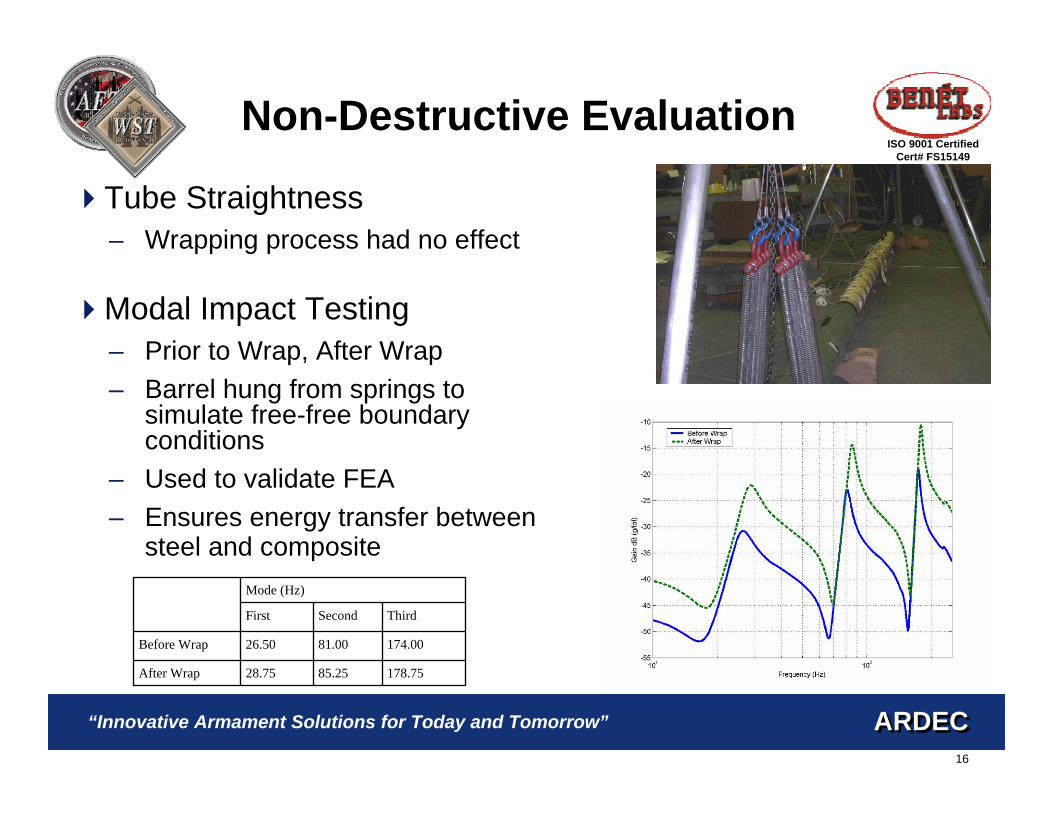
Modal impact testing was performed both prior to and
after applying the composite to determine the effect of the overwrap on tube stiffness. In all cases the tube was hung from springs to simulate free-free boundary conditions. This setup can be seen in Figure 3.
Accelerometers were placed at the muzzle and every
foot (304.8 mm) down the length of the composite. The tube was then impacted 219 mm from the muzzle and the response of the accelerometers was recorded. After this, all but the muzzle accelerometer were removed and the tube was then impacted at each previous accelerometer location.
The results of this testing for the first three modes can
be seen in Table 1. The composite wrap slightly increased the stiffness of the gun. These results were compared to the FEA analysis and were found to be in good agreement. Not only did this result help to validate the FEA models but also ensured that energy was being transferred from the composite to the steel and vice versa. The slight drop in frequency after firing was determined to be within acceptable test error.
TABLE 1–MODAL IMPACT TESTING RESULTS
Mode (Hz) First Second Third
Before Wrap 26.50 81.00 174.00 After Wrap 28.75 85.25 178.75 After Firing 28.25 83.50 173.75
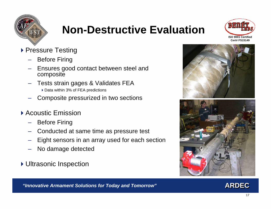
The pressure and AE tests were conducted at the same
time as they both required pressurizing the gun tube. The pressure test helps to ensure that there is no gap between the steel and the overwrap. If a gap exists then there would be a delay in the composite picking up the pressure load applied to the bore. For the AE test the tube is pressured twice. The first time there will be some fiber and matrix cracking as any defects need to work themselves out. The second loading should be quiet. If the second loading produces any noise events they could be an indication of damage and need to be investigated.
Standard rosette strain gages were placed at two axial
locations along the length of the composite. At each location a gage was placed at the 12, 3, 6 and 9 O'clock positions. The gauges were oriented to record both hoop and axial strain. These same gauges were later used in the
firing test. A mandrel was then inserted into the bore under the composite and was pressurized to 68.9 MPa (10 ksi). The strain readings were recorded every 6.89 MPa (1000 psi).
Eight Physical Acoustics R-151 acoustic emission
sensors were set up in an F-array so that the location of any suspected damage could be located. The mandrel used to pressurize the tube was only 1828.8 mm (72”) in length so the pressure/AE test was conducted twice to cover the entire length of the composite. Figure 4 shows the setup of the AE sensors for the second test area. The pressure data collected was within 3% of the FEA predictions. The post firing test showed no signs of degradation due to firing.
5. FIRING RESULTS In December 2004, May 2005 and July 2005 the gun
Figure 3–Modal testing setup
Figure 4–Acoustic Emission Test Setup
5
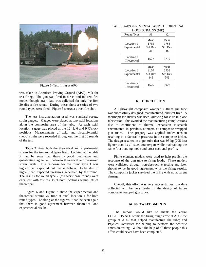
was taken to Aberdeen Proving Ground (APG), MD for test firing. The gun was fired in direct and indirect fire modes though strain data was collected for only the first 20 direct fire shots. During these shots a series of two round types were fired. Figure 5 shows a direct fire shot.
The test instrumentation used was standard rosette
strain gauges. Gauges were placed at two axial locations along the composite area of the tube. At each axial location a gage was placed at the 12, 3, 6 and 9 O'clock positions. Measurements of axial and circumferential (hoop) strain were recorded throughout the first 20 rounds of the test.
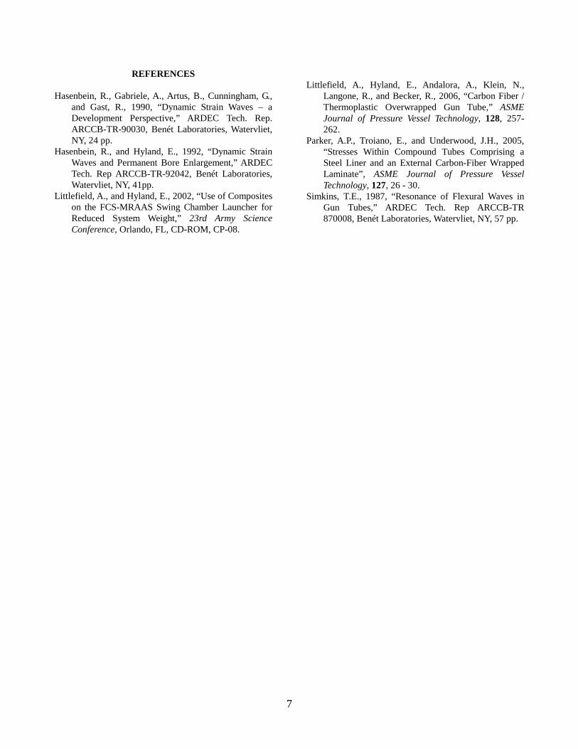
Table 2 gives both the theoretical and experimental
strains for the two round types fired. Looking at the table it can be seen that there is good qualitative and quantitative agreement between theoretical and measured strain levels. The response for the round type 1 was higher than expected but this is believed to be due to higher than expected pressures generated by the round. The results for round type 2 (the worst case round) were excellent with test results at both locations within 3% of theoretical.
Figure 6 and Figure 7 show the experimental and
theoretical strains vs. time at axial location 1 for both round types. Looking at the figures it can be seen again that there is good agreement between theoretical and experimental results.
6. CONCLUSION
A lightweight composite wrapped 120mm gun tube
was successfully designed, manufactured, and test fired. A thermoplastic matrix was used, allowing for cure in place fabrication. This avoided the manufacturing complications due to coefficient of thermal expansion mismatch encountered in previous attempts at composite wrapped gun tubes. The prepreg was applied under tension resulting in a favorable prestress in the composite jacket. The design resulted in a gun tube that was 93 kg (205 lbs) lighter than its all steel counterpart while maintaining the same first bending mode and cross sectional profile.
Finite element models were used to help predict the
response of the gun tube to firing loads. These models were validated through non-destructive testing and later shown to be in good agreement with the firing results. The composite jacket survived the firing with no apparent damage.
Overall, this effort was very successful and the data
collected will be very useful in the design of future composite wrapped gun tubes.
ACKNOWLEDGMENTS The authors would like to thank the entire
LOS/BLOS ATD team; the firing range crew at APG; the group at ADC that helped manufacture the tube; and Physical Acoustics for helping to perform the acoustic emission testing. Without the help of all these people this effort could never have been completed.
Figure 5–Test firing at APG
TABLE 2–EXPERIMENTAL AND THEORETICAL HOOP STRAINS (ME)
Round Type #1 #2
Location 1 Experimental
Mean 1755
Std Dev 33
Mean 1766
Std Dev 86
Location 1 Theoretical 1527 1719
Location 2 Experimental
Mean 2160
Std Dev 145
Mean 1933
Std Dev 289
Location 2 Theoretical 1575 1922

6
Figure 6–Experimental & theoretical Strain vs. time
Figure 7–Experimental & theoretical strain vs. time
7
REFERENCES
Hasenbein, R., Gabriele, A., Artus, B., Cunningham, G., and Gast, R., 1990, “Dynamic Strain Waves – a Development Perspective,” ARDEC Tech. Rep. ARCCB-TR-90030, Benét Laboratories, Watervliet, NY, 24 pp.
Hasenbein, R., and Hyland, E., 1992, “Dynamic Strain Waves and Permanent Bore Enlargement,” ARDEC Tech. Rep ARCCB-TR-92042, Benét Laboratories, Watervliet, NY, 41pp.
Littlefield, A., and Hyland, E., 2002, “Use of Composites on the FCS-MRAAS Swing Chamber Launcher for Reduced System Weight,” 23rd Army Science Conference, Orlando, FL, CD-ROM, CP-08.
Littlefield, A., Hyland, E., Andalora, A., Klein, N.,
Langone, R., and Becker, R., 2006, “Carbon Fiber / Thermoplastic Overwrapped Gun Tube,” ASME Journal of Pressure Vessel Technology, 128, 257-262.
Parker, A.P., Troiano, E., and Underwood, J.H., 2005, “Stresses Within Compound Tubes Comprising a Steel Liner and an External Carbon-Fiber Wrapped Laminate”, ASME Journal of Pressure Vessel Technology, 127, 26 - 30.
Simkins, T.E., 1987, “Resonance of Flexural Waves in Gun Tubes,” ARDEC Tech. Rep ARCCB-TR 870008, Benét Laboratories, Watervliet, NY, 57 pp.
28 Nov 2006Dr. Andrew Littlefield
[email protected]: (518) 266-3972
Fax: (518) 266-4149
PRESTRESSED CARBON FIBER COMPOSITE OVERWRAPPED GUN TUBEAndrew G. Littlefield and Edward HylandUS Army RDECOM-ARDEC Benét LaboratoriesWatervliet, NY 12189-4050
ARDECARDEC“Innovative Armament Solutions for Today and Tomorrow”
1
ARDECARDEC
ISO 9001 CertifiedCert# FS15149
“Innovative Armament Solutions for Today and Tomorrow”
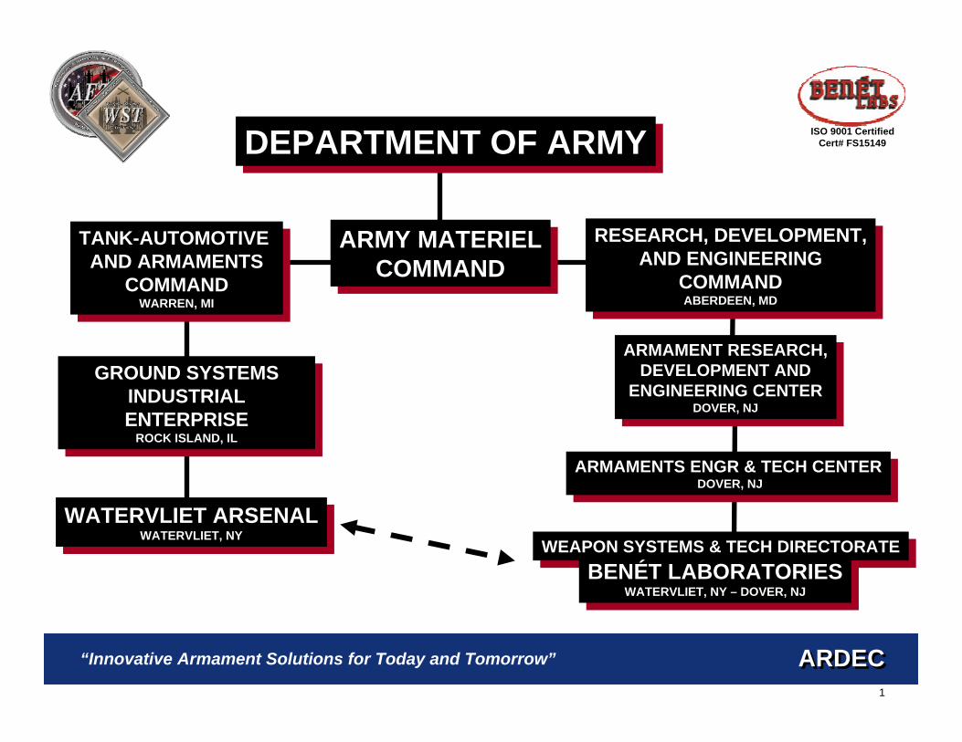
WATERVLIET ARSENALWATERVLIET, NY
WATERVLIET ARSENALWATERVLIET, NY
GROUND SYSTEMSINDUSTRIAL ENTERPRISE
ROCK ISLAND, IL
GROUND SYSTEMSINDUSTRIAL ENTERPRISE
ROCK ISLAND, IL
DEPARTMENT OF ARMYDEPARTMENT OF ARMY
ARMY MATERIELCOMMAND
ARMY MATERIELCOMMAND
TANK-AUTOMOTIVE AND ARMAMENTS
COMMANDWARREN, MI
TANK-AUTOMOTIVE AND ARMAMENTS
COMMANDWARREN, MI
WEAPON SYSTEMS & TECH DIRECTORATEWEAPON SYSTEMS & TECH DIRECTORATE
BENÉT LABORATORIESWATERVLIET, NY – DOVER, NJ
BENÉT LABORATORIESWATERVLIET, NY – DOVER, NJ
ARMAMENT RESEARCH,DEVELOPMENT AND
ENGINEERING CENTERDOVER, NJ
ARMAMENT RESEARCH,DEVELOPMENT AND
ENGINEERING CENTERDOVER, NJ
RESEARCH, DEVELOPMENT,AND ENGINEERING
COMMANDABERDEEN, MD
RESEARCH, DEVELOPMENT,AND ENGINEERING
COMMANDABERDEEN, MD
ARMAMENTS ENGR & TECH CENTERDOVER, NJ
ARMAMENTS ENGR & TECH CENTERDOVER, NJ
2
ARDECARDEC
ISO 9001 CertifiedCert# FS15149
“Innovative Armament Solutions for Today and Tomorrow”
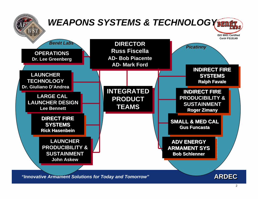
LAUNCHERTECHNOLOGY
Dr. Giuliano D’Andrea
LAUNCHERTECHNOLOGY
Dr. Giuliano D’AndreaINTEGRATED
PRODUCTTEAMS
INTEGRATEDPRODUCT
TEAMS
WEAPONS SYSTEMS & TECHNOLOGY
LARGE CAL LAUNCHER DESIGN
Lee Bennett
LARGE CAL LAUNCHER DESIGN
Lee Bennett
LAUNCHERPRODUCIBILITY &
SUSTAINMENTJohn Askew
LAUNCHERPRODUCIBILITY &
SUSTAINMENTJohn Askew
OPERATIONSDr. Lee GreenbergOPERATIONS
Dr. Lee Greenberg
DIRECTOR Russ Fiscella
AD- Bob PiacenteAD- Mark Ford
DIRECTOR Russ Fiscella
AD- Bob PiacenteAD- Mark Ford
DIRECT FIREDIRECT FIRESYSTEMSSYSTEMS
Rick HasenbeinRick Hasenbein
INDIRECT FIREINDIRECT FIRESYSTEMSSYSTEMS
Ralph FavaleRalph Favale
SMALL & MED CALSMALL & MED CALGus FuncastaGus Funcasta
ADV ENERGYADV ENERGYARMAMENT SYSARMAMENT SYS
Bob SchlennerBob Schlenner
Core Capability Teams
INDIRECT FIREINDIRECT FIREPRODUCIBILITY &
SUSTAINMENTRoger ZimanyRoger Zimany
PicatinnyPicatinnyBenBenéét Labst Labs
3
ARDECARDEC
ISO 9001 CertifiedCert# FS15149
“Innovative Armament Solutions for Today and Tomorrow”
4
ARDECARDEC
ISO 9001 CertifiedCert# FS15149
“Innovative Armament Solutions for Today and Tomorrow”
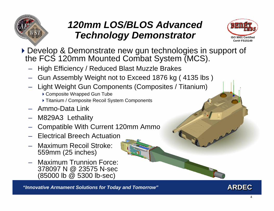
120mm LOS/BLOS Advanced Technology Demonstrator
Develop & Demonstrate new gun technologies in support of the FCS 120mm Mounted Combat System (MCS).– High Efficiency / Reduced Blast Muzzle Brakes– Gun Assembly Weight not to Exceed 1876 kg ( 4135 lbs )– Light Weight Gun Components (Composites / Titanium)
Composite Wrapped Gun TubeTitanium / Composite Recoil System Components
– Ammo-Data Link– M829A3 Lethality– Compatible With Current 120mm Ammo– Electrical Breech Actuation– Maximum Recoil Stroke:
559mm (25 inches)– Maximum Trunnion Force:
378097 N @ 23575 N-sec(85000 lb @ 5300 lb-sec)

5
ARDECARDEC
ISO 9001 CertifiedCert# FS15149
“Innovative Armament Solutions for Today and Tomorrow”
Why Use Composite Materials?
Need to lighten the muzzle end of the gun– Center of Gravity (CG) of the tube is forward of the
trunnions
Need to stiffen the gun– Desire a higher natural
frequency to increase pointing accuracy
Need to combat dynamic strain effect– High projectile velocity causes strains to be amplified up to
seven time static levels
6
ARDECARDEC
ISO 9001 CertifiedCert# FS15149
“Innovative Armament Solutions for Today and Tomorrow”
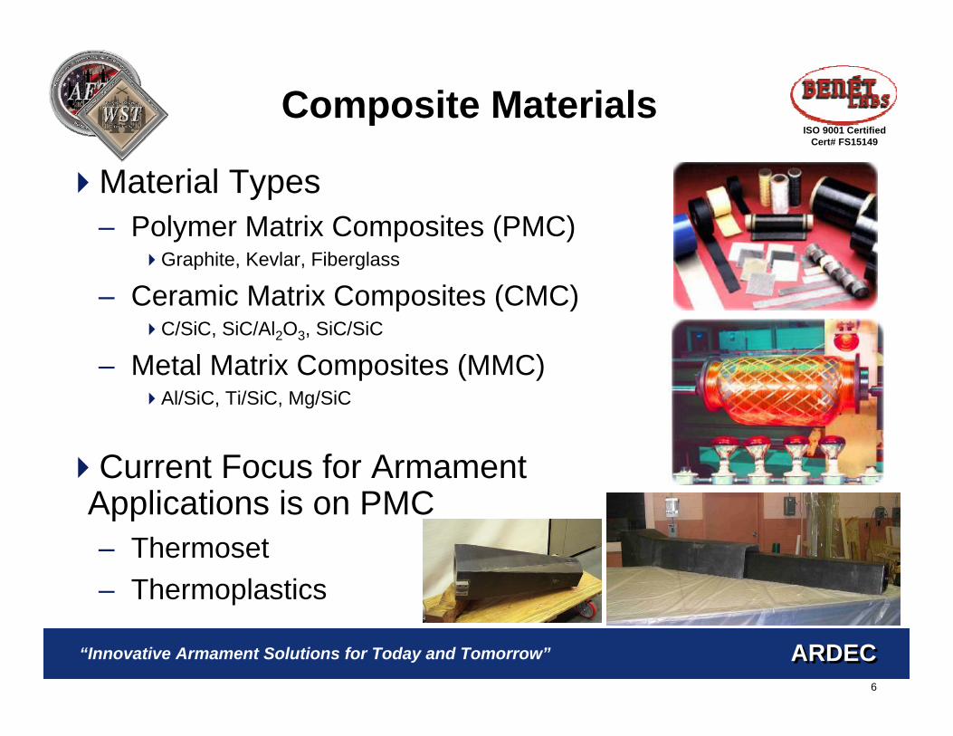
Composite Materials
Material Types– Polymer Matrix Composites (PMC)
Graphite, Kevlar, Fiberglass
– Ceramic Matrix Composites (CMC)C/SiC, SiC/Al2O3, SiC/SiC
– Metal Matrix Composites (MMC)Al/SiC, Ti/SiC, Mg/SiC
Current Focus for Armament Applications is on PMC– Thermoset– Thermoplastics

7
ARDECARDEC
ISO 9001 CertifiedCert# FS15149
“Innovative Armament Solutions for Today and Tomorrow”
Previous Work in CompositeGun Tubes
20 years of Benét expertise in composite cannon development, manufacture, and testing.– Organic Fiberglass 105mm (No Pre-stress)– Titanium Jacketed 120mm (Swage Pre-stress)– Metal Matrix Composite 120mm (Swage Pre-stress)– Organic Composite 120mm (Swage Pre-stress)– Organic Thermoset 105mm MRAAS
(Lay-up Tailoring – No Pre-stress) – Electromagnetic Railgun Tubes– E-Beam and Tape Placement Stub Tubes

8
ARDECARDEC
ISO 9001 CertifiedCert# FS15149
“Innovative Armament Solutions for Today and Tomorrow”
FCS-MRAAS Swing ChamberLauncher
105mm Organic Thermoset Overwrap– Designed in conjunction with the University of
Delaware Center for Composite Materials– CTE mismatch handled by layup tailoring – Hoop fibers applied by filament winder– Axial fibers hand laid up– Not wound in tension – no pre-stress– Oven cured
TestFiredJuly2003

9
ARDECARDEC
ISO 9001 CertifiedCert# FS15149
“Innovative Armament Solutions for Today and Tomorrow”
Greatest Payoff in Terms of Weight Reduction is Accrued by UsingComposite Overwrap.– Need to reduce weight at muzzle to help with imbalance
Must be Proper Adherence Between Jacket and Tube to Gain Benefits of Increased Axial Thickness And Minimizing Dynamic Strain– Autofrettage will force tube and overwrap into contact but greatly complicates
manufacturing process– Tailoring layup allows use of standard winding/oven cure but compromises
properties and labor intensive– Thermoplastic tape placement shows promise for high interface
strength and reduced labor
Want High Overwrap Prestress– Available with both normal filament
winding and tape placement
Conclusions from Prior Work
10
ARDECARDEC
ISO 9001 CertifiedCert# FS15149
“Innovative Armament Solutions for Today and Tomorrow”
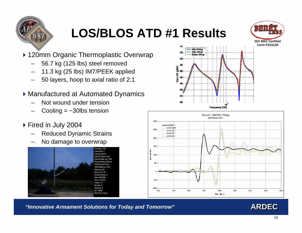
LOS/BLOS ATD #1 Results120mm Organic Thermoplastic Overwrap
– 56.7 kg (125 lbs) steel removed– 11.3 kg (25 lbs) IM7/PEEK applied– 50 layers, hoop to axial ratio of 2:1
Manufactured at Automated Dynamics– Not wound under tension– Cooling = ~30lbs tension
Fired in July 2004 – Reduced Dynamic Strains– No damage to overwrap
11
ARDECARDEC
ISO 9001 CertifiedCert# FS15149
“Innovative Armament Solutions for Today and Tomorrow”
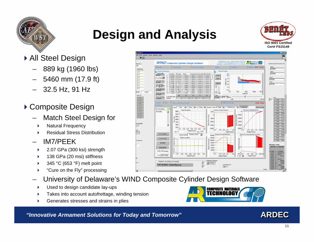
Design and Analysis
All Steel Design– 889 kg (1960 lbs)– 5460 mm (17.9 ft)– 32.5 Hz, 91 Hz
Composite Design– Match Steel Design for
Natural FrequencyResidual Stress Distribution
– IM7/PEEK 2.07 GPa (300 ksi) strength138 GPa (20 msi) stiffness345 °C (653 °F) melt point“Cure on the Fly” processing
– University of Delaware’s WIND Composite Cylinder Design SoftwareUsed to design candidate lay-upsTakes into account autofrettage, winding tensionGenerates stresses and strains in plies

12
ARDECARDEC
ISO 9001 CertifiedCert# FS15149
“Innovative Armament Solutions for Today and Tomorrow”
Design and Analysis
Finite Element Modeling– ABAQUS Standard
Axisymmetric, CAX8RStatic, Normal Mode, Dynamic
Final Design– 72 layers, hoop to axial ratio of 2:1– Additional +/- 45 S2 glass ply added for
protection– Hoop layers wound under 60lbs of
tension to match residual stress distribution of the original steel design
– Removed 113.4 kg (250 lbs) steel– Applied 20.4 kg (45 lbs) composite

13
ARDECARDEC
ISO 9001 CertifiedCert# FS15149
“Innovative Armament Solutions for Today and Tomorrow”
Manufacture
Steel Portion Manufactured Normally– Portion was undercut and not painted for the
composite– Straightness Checked Prior to Wrap– Natural Frequency Measured Prior to Wrap
Overwrap Applied by Automated Dynamics– Utilized Robotics and Fiber Placement
HeadsPrecise Fiber Placement and ConsolidationWind Angles of -180° to 180°
– Three Major IssuesTightness of OverwindGalvanic CorrosionPrecise OD specifications
14
ARDECARDEC
ISO 9001 CertifiedCert# FS15149
“Innovative Armament Solutions for Today and Tomorrow”
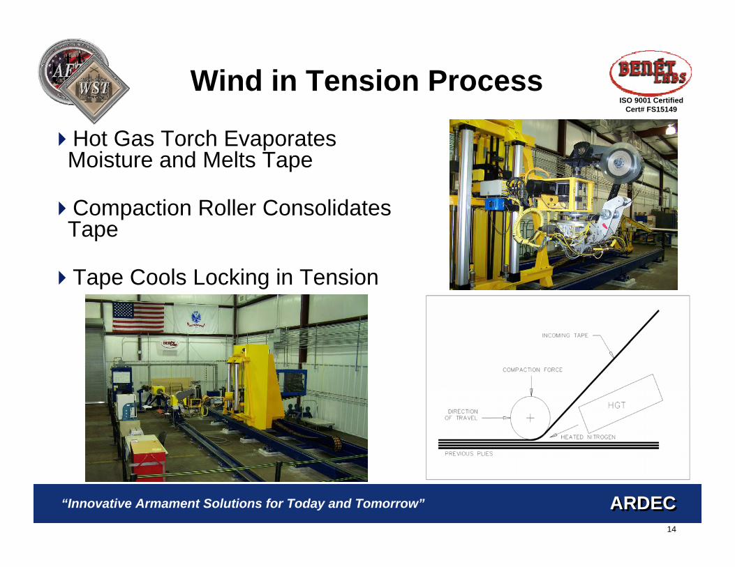
Hot Gas Torch Evaporates Moisture and Melts Tape
Compaction Roller Consolidates Tape
Tape Cools Locking in Tension
Wind in Tension Process

15
ARDECARDEC
ISO 9001 CertifiedCert# FS15149
“Innovative Armament Solutions for Today and Tomorrow”
ManufactureTightness of Overwind
– Barrel cooled to sub zero temperatures and maintained there during processing
– Introduces prestress due to CTE mismatch– Cooling helps to remove heat generated by the
process– Hot gas torch vaporizes condensation
Galvanic Corrosion– Carbon fiber would react with steel– Insulating layer of S2/Peek prevents this– S2/Peek layer was accounted for in the FEA model
OD Specifications– Ply count varied over overwrap length– Close attention paid to OD during wrap– Modifications to ply lengths and start/stop locations
made to account for material variations (+/- 0.0127 mm allowed by material specification)
16
ARDECARDEC
ISO 9001 CertifiedCert# FS15149
“Innovative Armament Solutions for Today and Tomorrow”
Non-Destructive Evaluation
Tube Straightness– Wrapping process had no effect
Modal Impact Testing– Prior to Wrap, After Wrap – Barrel hung from springs to
simulate free-free boundary conditions
– Used to validate FEA– Ensures energy transfer between
steel and composite
178.7585.2528.75After Wrap
174.0081.0026.50Before Wrap
ThirdSecondFirst
Mode (Hz)
17
ARDECARDEC
ISO 9001 CertifiedCert# FS15149
“Innovative Armament Solutions for Today and Tomorrow”
Non-Destructive Evaluation
Pressure Testing– Before Firing– Ensures good contact between steel and
composite– Tests strain gages & Validates FEA
Data within 3% of FEA predictions
– Composite pressurized in two sections
Acoustic Emission– Before Firing– Conducted at same time as pressure test– Eight sensors in an array used for each section– No damage detected
Ultrasonic Inspection

18
ARDECARDEC
ISO 9001 CertifiedCert# FS15149
“Innovative Armament Solutions for Today and Tomorrow”
FiringFired in Dec 2004, May 2005, and Jul 2005 at Aberdeen Proving Ground
Fired in Direct and Indirect Fire Modes– Over 90 rounds fired total
Strain Data Collected for first 20 Direct Fire Rounds– Strain gauge rosettes placed two
axial locations along the composite– At each location a gauge was
placed at 12, 3, 6, and 9 O’clock positions
– Hoop and axial strain measured at each gauge
– Several gauges were lost during the test

19
ARDECARDEC
ISO 9001 CertifiedCert# FS15149
“Innovative Armament Solutions for Today and Tomorrow”
Firing Results
19221575Location 2 Theoretical
Mean1933
Std Dev289
Mean2160
Std Dev145
Location 2 Experimental
17191527Location 1 Theoretical
Mean1766
Std Dev86
Mean1755
Std Dev33
Location 1 Experimental
#2#1Round Type

20
ARDECARDEC
ISO 9001 CertifiedCert# FS15149
“Innovative Armament Solutions for Today and Tomorrow”
Post Firing NDE
Repeated Modal, Pressure and acoustic emission testing
No indications of damage were found
Tube is being used for motion platform testing for the SDD program so it could not be cut up

21
ARDECARDEC
ISO 9001 CertifiedCert# FS15149
“Innovative Armament Solutions for Today and Tomorrow”
ConclusionsLightweight 120mm Prestressed Thermoplastic Overwrapped Gun Tube was Manufactured and Tested– Use of composite resulted in net weights savings of 93 kg (205 lbs)
Use of Thermoplastics Allowed for Cure in Place Processing– Avoided manufacturing complications inherent with thermosets– CTE mismatch helped to achieve prestress instead of forming a gap
FEA Modeling Used to Predict Firing Response– Validated via modal and pressure testing– Good agreement found with firing data
Composite Jacket Survived Firing with No Apparent Damage
This Design has been picked as the baseline for SDD for the XM360– Tube #5 has wrapped in Jan 06 and tested late Spring– First SDD tube will be made in Dec 06 at Benét