a vertical - bnl notes/tn183.pdf · the ags equilibrium orbit measuring system is ... three effects...
TRANSCRIPT
Accelera tor Department BROOKHAVEN NATIONAL LABORATORY Associated U n i v e r s i t i e s , Inc.
Upton, New York 11973
AGS Divis ion Technical Note No. 183
THE DEAD RECKONING OF THE AGS RING PUE SYSTEM
L. Ahrens
November 24, 1982
The AGS equi l ibr ium o r b i t measuring system is composed of 72 e l e c t r o d e
(PUE) sets each of which produces a ver t ica l and h o r i z o n t a l p o s i t i o n f o r
t h e beam cen t ro id f o r t h a t azimuthal p o s i t i o n around t h e r i n g . Each PUE
s e t - c o n s i s t s of two h o r i z o n t a l and two ver t ica l p l a t e s r i g i d l y f i x e d wi th in
a m e t a l s h i e l d tube which i t s e l f is appropr i a t e ly pos i t ioned wi th in t h e
vacuum chamber. The p l a t e s couple c a p a c i t i v e l y t o t h e passing beam bunches.
P o s i t i o n i s deduced by t ak ing d i f f e r e n c e s between t h e s i g n a l s measured on
t h e p l a t e s ( V l , V2) normalized t o t h e sum, wi th an o v e r a l l p r o p o r t i o n a l i t y
cons tan t f i x e d by t h e geometry: POS=K&(Vl-V2)/(Vl+V2). K i s approximately
5 c m f o r t h e r i n g PUE's.
Discrepencies between t h e deduced p o s i t i o n s and t h e t r u e beam p o s i t i o n s
can be i n t e r p r e t e d as an o f f s e t , a ( l i n e a r ) ga in e r r o r , and h igher o rde r t e r m s .
I n f a c t t h e p l a t e s are pos i t ioned such t h a t a beam centered i n t h e a p e r a t u r e
i s a l s o centered i n t h e PUE s t r u c t u r e t o a few m i l l i m e t e r s so t h e above expan-
s i o n i s appropr i a t e .
equa l , t h e system s t i l l g ives approximately v a l i d information when used i n
a n u l l i n g mode. Quan t i t a t ive ly , i f t h e ga in of one s i d e d i f f e r s from t h e
o the r by t h e f a c t o r ( I f E ) , t h e r e s u l t i n g o f f s e t i s E*(K/2). A 10% gain d i f -
f e r ence causes an apparent o f f s e t of 2.5mm.
That i s , even i f t h e ga ins of a PUE p a i r are n o t q u i t e
This n o t e i s concerned w i t h o f f s e t s caused by e r r o r s i n t h e system up-
stream of t h e e l e c t r o n i c s . Thkse o f f s e t s are e s s e n t i a l l y impossible t o d i s -
t i n g u i s h from real o f f s e t s i n t h e equi l ibr ium orb i t - - the l a t te r of course
being t h e information one i s a f t e r .
be removed by a dead reckoning procedure-e i ther c o r r e c t i n g t h e cause i n t h e
Therefore t h e s e erroneous o f f s e t s must
-2- AGS Div. Tech. Note #183
hardware o r t h e r e s u l t i n g e f f e c t s i n t h e sof tware.
t i o n s t h e sof tware c o r r e c t i o n course i S adopted here.
t h e magnitudes of t h e e f f e c t s are measured.
For p r a c t i c a l considera-
A s a u s e f u l byproduct
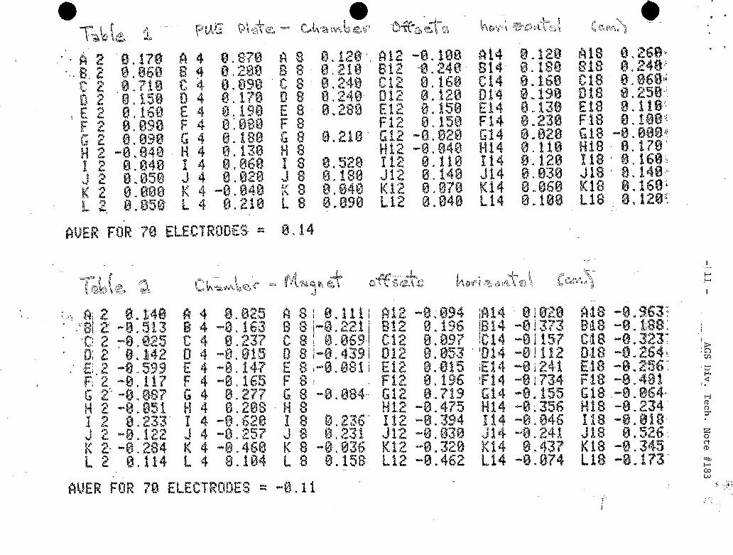
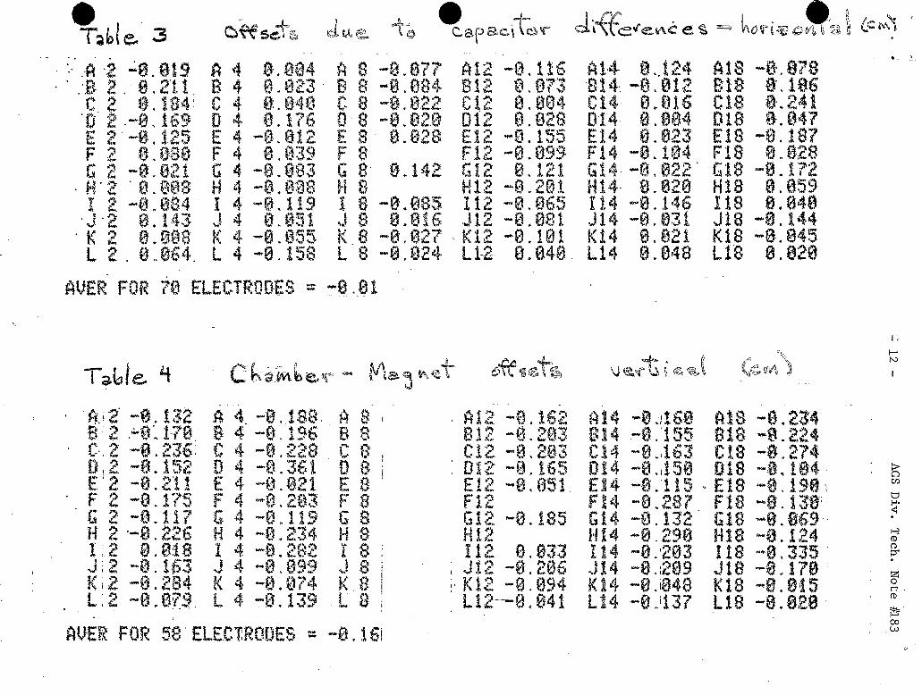
Three o f f s e t sources are considered: a) t h e p la tes may be improperly
pos i t ioned wi th in t h e vacuum chamber, b) t h e vacuu.m chamber may be improperly
pos i t ioned wi th in t h e magnets, and c) t h e capac i tances of t h e two p l a t e s con-
t r i b u t i n g t o a measurement may n o t be equal.
whose e f f e c t is i d e n t i c a l t o t h a t of a ga in i n e q u a l i t y i n t h e e l e c t r o n i c s .
It is considered h e r e because as configured t h e system does n o t a l low t h i s
component t o be measured whi le t h e beam is up.
have been measured f o r t h e system, ( ( a ) f o r t h e v e r t i c a l i s n o t y e t done),
and t h e r e s u l t i n g p red ic t ed e r r o r s are co r rec t ed i n measured o r b i t s us ing a
t a b l e s t o r e d i n t h e computer. The remainder of t h e n o t e w i l l very b r i e f l y
desc r ibe t h e methods used t o measure t h e t h r e e e f f e c t s and p resen t t h e r e s u l t -
ing o f f s e t s .
Cause e ) is a ga in i n e q u a l i t y
These t h r e e c o n t r i b u t i o n s
Error (a) i s i n t h e f i r s t p l ace minimized by us ing a p r e c i s i o n j i g t o
a l i g n t h e p l a t e s re la t ive t o t h e vacuum chamber.
enc los ing s h i e l d tube are o f f s e t from t h e chamber c e n t e r l i n e t o a c e n t e r on
t h e beam code axis. The magnitude of t h e o f f s e t i s d i f f e r e n t f o r t h e t h r e e
d i f f e r e n t l a t t i c e p o s i t i o n s he ld by t h e PUEs, and is of o rde r 5mm.
of a s i m p l i f i c a t i o n i n t h e assembly procedure, t h e j i g must be r o t a t e d by 180
degrees about t h e beam axis i n going from PUEs i n t h e first h a l f of a super-
per iod t o those i n t h e second h a l f . I f t h i s r o t a t i o n i s fo rgo t t en , o r i f a
chamber i s moved from t h e second h a l f t o t h e f i r s t h a l f without real ignment ,
an o f f s e t e r r o r of approximately LOmm w i l l r e s u l t .
The curved p l a t e s and t h e
a
A s a r e s u l t
The method t o check t h i s p o s i t i o n a f t e r assembly is no t obvious s i n c e
breaking t h e r i n g vacuum and p u l l i n g chambers and magnets t o a l low access
would almost c e r t a i n l y do more harm than good. Following a sugges t ion of
D r . A'. Maschke t h e u s e of a p o r t a b l e x-ray machine t o image t h e p l a t e s on a
f i l m w a s i nves t iga t ed and found t o be f e a s i b l e .
p l a t e p o s i t i o n s have been measured.
t h e i n s i d e and o u t s i d e p l a t e s , and t h e ad jacen t s h i e l d tube and chamber edge
w e r e taken, a l lowing an independent e s t ima t ion of t h e accuracy of t h e proce-
dure, given t h e known chamber and s h i e l d tube r a d i i .
I n t h i s way t h e h o r i z o n t a l
For a subse t of PUEs, p i c t u r e s of bo th
The measurement e r r o r
-3- AGS D i v . Tech. Note # 183
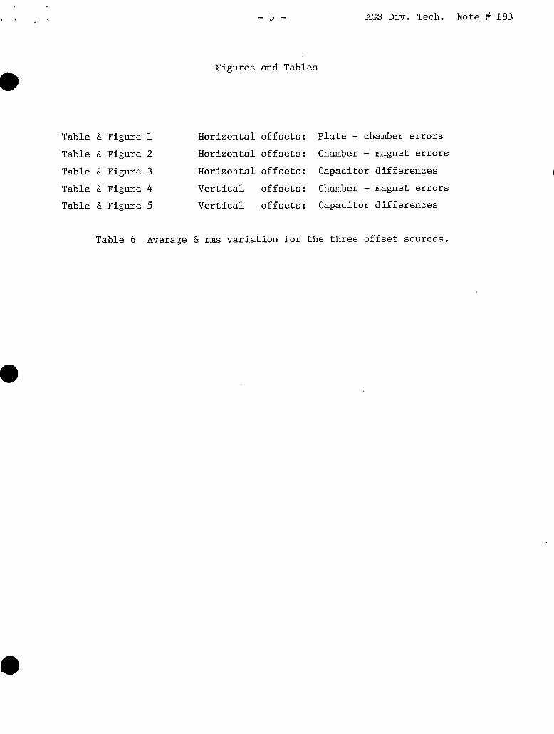
d i s t r i b u t i o n width w a s approximately 0.5mm (rms). From-this da t a th ree
PUEs w e r e found t o be mispositioned by approximately lOmm, and i n t h e direc-
t i o n expected by the above mentioned poss ib le j i g misuse. The rest were
d i s t r i b u t e d with an nns v a r i a t i o n of 0.8mm about a mean o f f s e t of lmm.
These da ta are given i n f i g u r e 1 and t a b l e 1.
j i g posit ioning e r r o r approximately equal t o the e r r o r i n the measurement
technique. The mean o f f s e t i s not c l e a r l y understood. However, t h e x-ray
r e s u l t s use t h e edge of t h e sh i e ld tube a t i t s extreme downstream edge as
the pos i t ion reference, while t h e j i g picks up the center l i n e of one of t h e
attached p l a t e s . A t any rate, an over a l l r a d i a l o f f s e t of t h e PUEs i s of
s m a l l consequence being equivalent t o a momentum s h i f t .
be applied t o the v e r t i c a l PUEs during the coming year.
* The r e s u l t s im$y an average
The procedure w i l l
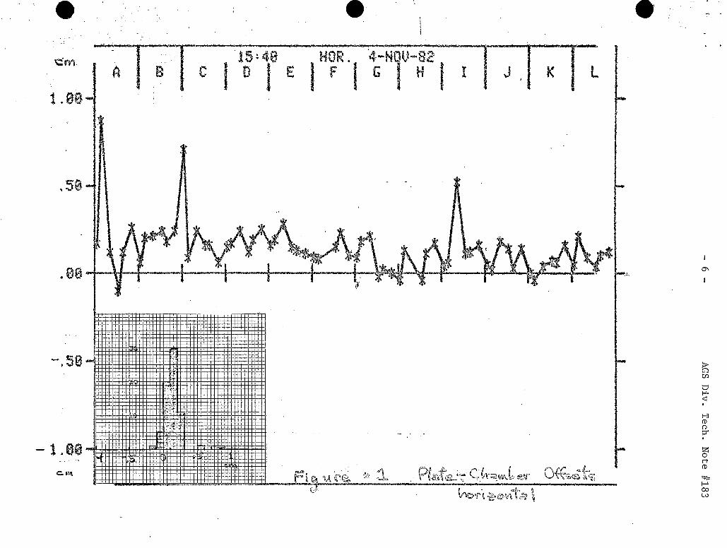
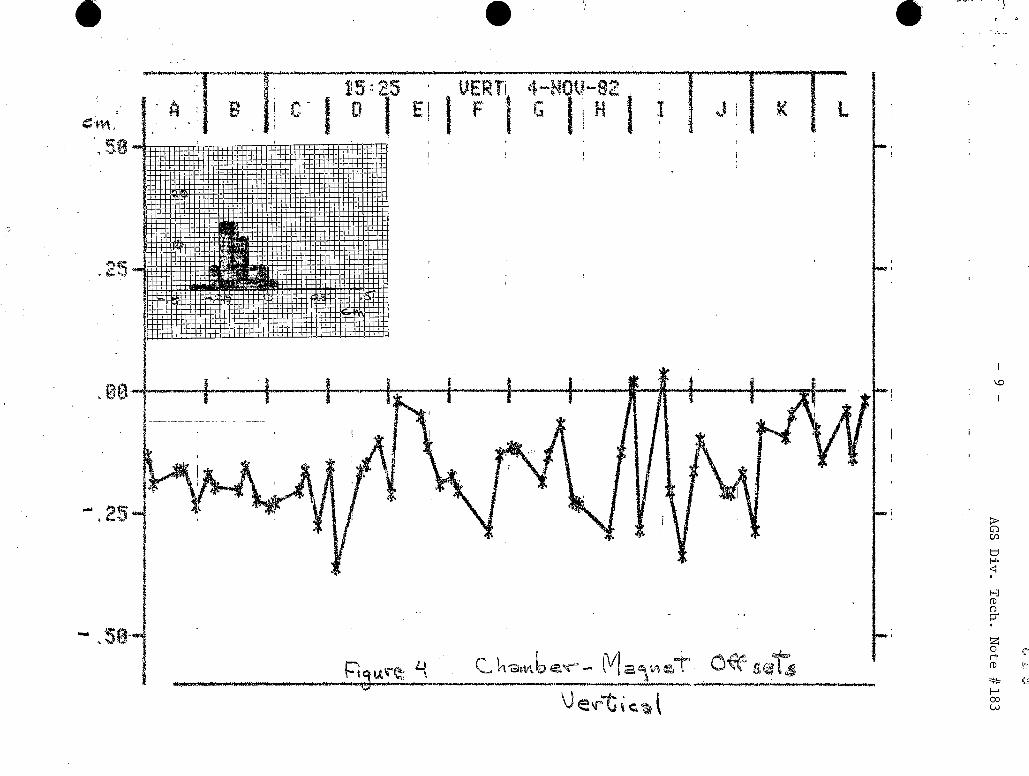
Error source (b), t h e pos i t ion of t h e vacuum chamber holding t h e PUE
assembly r e l a t i v e t o t h e magnets, has r ecen t ly been measured using a sub-
s t a n t i a l j i g which references from t h e nea res t upstream and downstream magnet
socket holes.
t he vacuum chamber outs ide t h e PUE. The method gives reproducible r e s u l t s
t o wi th in a few m i l s , t h e l a r g e s t e r r o r being assoc ia ted with t h e l eve l ing
of t h e assemb.ly.
magnets involved are positioned re la t ive t o one another according t o t h e
survey data. Figures and t a b l e s 2 and 4 give t h e r e s u l t s from t h i s work.
The chambers are found t o be sys temat ica l ly low - they rest on t h e bottom
of t h e magnet gaps- but t h e vertical spread is narrower than t h e hor izonta l ,
t h e v e r t i c a l being more t i g h t l y constrained by t h e magnet geometry.
Pins driven by micrometer heads p ick up t h e top and s ides of
The i n t e r p r e t a t i o n of t h e measurement assumes t h a t t h e two
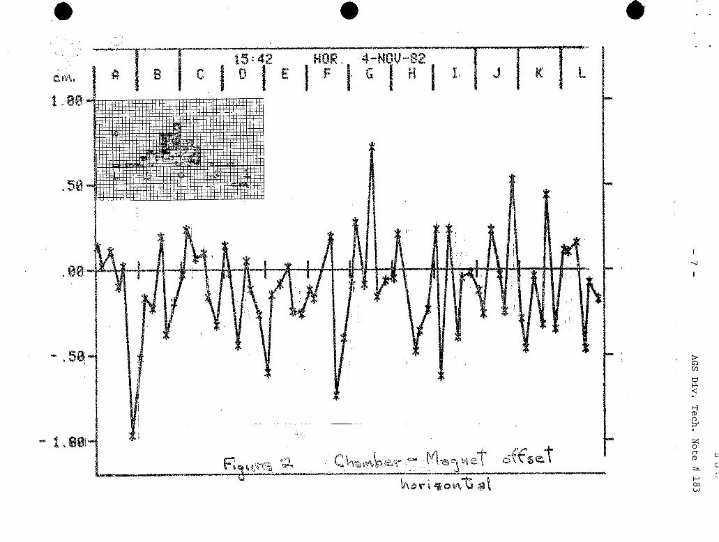
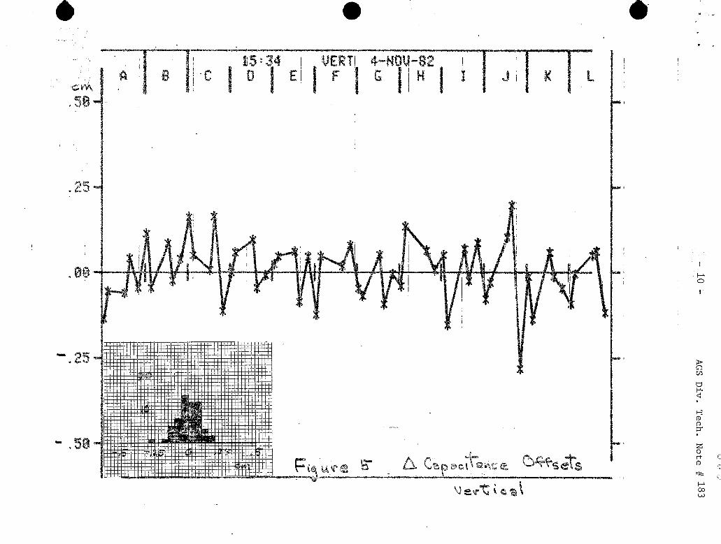
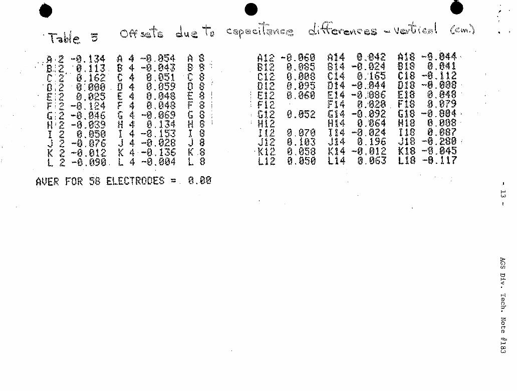
F ina l ly e r r o r (c ) , t h e capacitance inequal i ty , i s considered. The
capacitance i n each p l a t e system, upstream of t h e impedance matching trans-
former, i s approximately 90 pf. Or ig ina l ly t h i s capaciance w a s put i n
paral le l with a prec is ion 500 pf. capac i tor e f f e c t i v e l y causing s m a l l varia-
t i o n s i n t h e p l a t e system t o be swamped out , but reducing t h e ava i l ab le vol t -
age by t h e sane f a c t o r (X5). It w a s judged preferab le t o remove t h e l a r g e
capacitor and take both t h e ga in increase and t h e increased s e n s i t i v i t y t o
capacitance va r i a t ion .
af a ( 4 x 72) element t a b l e but a l s o gives some information about t h e s t a b i l -
i t y of t he system which may have independent value.
Monitoring of t h e capac i tors r equ i r e s t h e maintainance
Using t h e r e l a t i o n l i s t e d
AGS Div. Tech. Note #183 . s
-4-
ea r ly on, a one picofarad v a r i a t i o n away from t h e t a b l e values i n t h e d i f -
ference between t h e p l a t e s involved i n one measurement corresponds t o a
spurious o f f s e t of (1/180)*5cm,= .25mm. Difference r ep roduc ib i l i t y a t t h i s
level f o r healthy channels has been obtained f o r measurements taken over a
period of a year.
by thecapacitancemeasurements.
Figures and t a b l e s 3 and 5 r epor t t h e cor rec t ions required
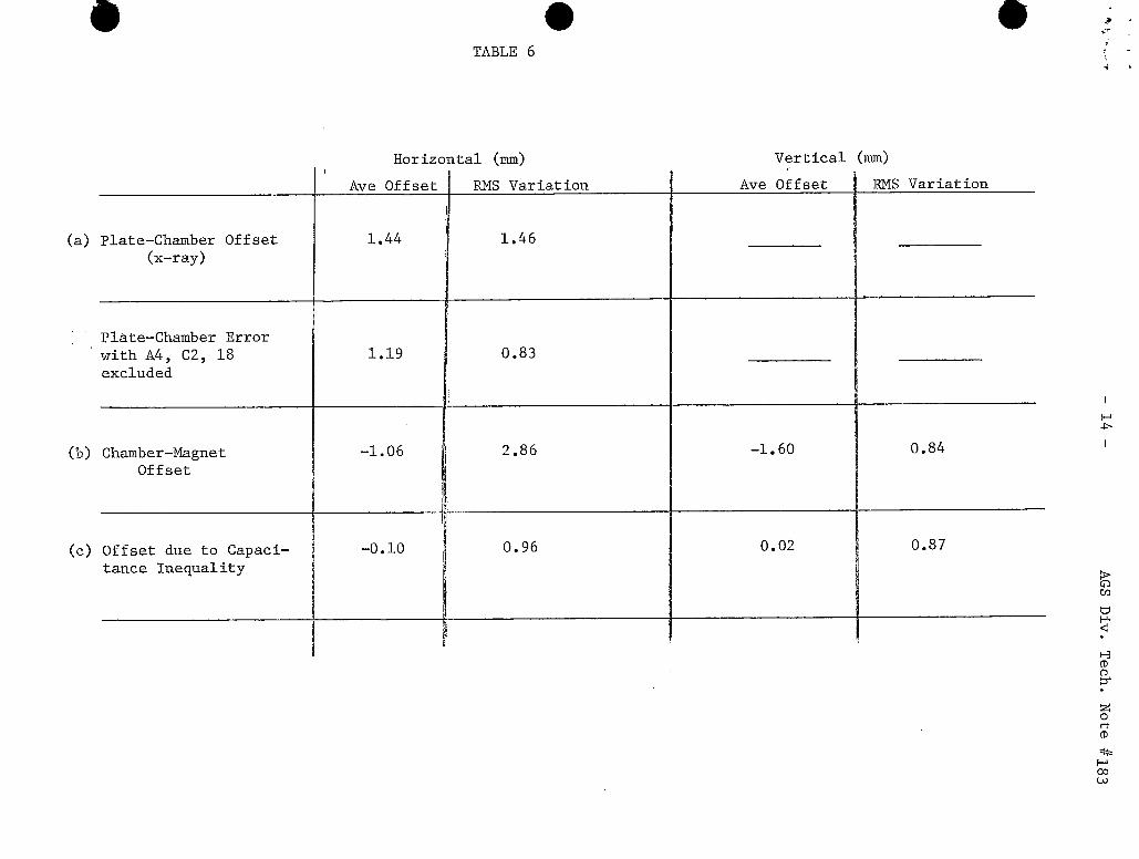
I n conclusion, t h r e e sources of PUE o f f s e t e r r o r s have been measured and
can be corrected f o r i n generating beam equilibrium o r b i t s using t a b l e s i n
t h e software. A summary of t h e r e s u l t s i s given in t a b l e 6. A p e s s i m i s t
would poin t ou t t h a t f o r t h e applied cor rec t ions t o be v a l i d these t a b l e s
must be r i g h t t o begin with (one s ign e r r o r is t w i e e as bad as doing nothing),
and must remain up t o d a t e as changes occur i n t h e r ing .
sumably g ran t t h a t t h e order of magnitude of t h e e r r o r s r e s u l t i n g form t h e
th ree e f f e c t s inves t iga ted has been es tab l i shed , which i n i t s e l f has s ign i -
f icance i n pred ic t ing t h e o v e r a l l accuracy t o be expected of t h e system.
Even he would pre-
Many AGS personnel have contributed t o these measurements. I n pae t i cu la r ,
M r . Nick Parnello and h i s s t a f f have been extremely he lpfu l both i n the organ-
i za t ion and execution of t h e x-ray work and i n t h e c rea t ion of t h e magnet
referencing j i g .
qua l i t y con t ro l personnel, and i n p a r t i c u l a r M r . Fred Conners w a s e s s e n t i a l
in working out t h e set up parameters.
The x-ray u n i t i t s e l f came from and w a s manned by B.N.L.
Dis t r ibu t ion: Dept. Administration R. DiPranco E. G i l l J.W. Glenn S. Naase R. Sanders
- 5 - AGS Div. Tech. Note fl 183
F igures and Tables
Table & Figure 1 Hor izonta l o f f s e t s : P l a t e - chamber e r r o r s
Table & Figure 2 Hor izonta l o f f s e t s : Chamber - magnet e r r o r s
Table & Figure 3 Hor i zon ta l o f f s e t s : Capaci tor d i f f e r e n c e s
Table & Figure 4 Vertical o f f s e t s : Chamber - magnet e r r o r s
Table & Figure 5 Vertical o f f s e t s : Capaci tor d i f f e r e n c e s
Table 6 Average & r m s v a r i a t i o n f o r the three o f f s e t sources .
..
-
6-
1.. 9.;
,_.
AG
S Div.
Tech.
Note #183
s Y
34
-3
1
t
* e.
-7
-
11 3jl :
AG
S Div.
Tech.
Note
w
._.
W-
e
i L 9
AG
S D
iv. T
ech. N
ote 8183
0
. ..
P.4- -
- lo -
. ..
AG
S D
iv. T
ech. N
ote # 183
.. -5
e-
",
't -,
I
-I11 - A
GS D
iv. T
ech. N
ote 1,183 ':
..
- 12 - AG
S D
iv. T
ech. N
o&
k8
3
~
ti
.*
=.
..
.,
.,
.I
--*.,..
c - 13 -
AGS Div.
Tech.
Note #183
*,
,-
4 $
'^
.r - 14 -
AG
S Div.
Tech.
Note #
l83
,
*
a
d
rl
4-
rl
-? U
al m LH
w
0
$4 a
n
Ph
SI
ux
I
-
a, 4J cd rl
PI n
rd
!E
v
m
co 0
cn rl
rl
d
co 0
Lo co c\l
a
0
rl
I
I- co 0
c\l 0
0
a
cn 0
0
rl
0
I n
U v