a wireless system for monitoring leakage current in
TRANSCRIPT

Received April 23, 2016, accepted May 6, 2016, date of publication June 9, 2016, date of current version July 7, 2016.
Digital Object Identifier 10.1109/ACCESS.2016.2577553
A Wireless System for Monitoring LeakageCurrent in Electrical Substation EquipmentN. HARID1, (Member, IEEE), A. C. BOGIAS2, H. GRIFFITHS1, (Member, IEEE),S. ROBSON2, (Member, IEEE), AND A. HADDAD2, (Member, IEEE)1The Petroleum Institute, 2533, Abu Dhabi, United Arab Emirates2School of Engineering, Cardiff University, Cardiff CF24 3AA, U.K.
Corresponding author: N. Harid ([email protected])
This work was supported by the U.K. Engineering and Physical Sciences Research Council under Grant EPSRC CASE/CAN/06/23.
ABSTRACT In this paper, the design and the development of a remote system for continuous monitoring ofleakage currents and ground currents in high voltage electrical substations are proposed. Based on wirelesslocal area network technology, the system can be used to monitor continuously a variety of plants within thesubstation and has low power consumption with inbuilt overvoltage protection. It consists of a transmittermodule equipped with a data acquisition (DAQ) system connected to leakage current and voltage sensors,and a receiver module connected to a remote controller for data processing and storage. The principle ofoperation and the characteristics of the various components of the system are described. Validation testshave been used to verify its performance in three different test situations: A) laboratory monitoring of theleakage current and voltage of a distribution surge arrester; B) laboratory measurement of the leakage currentof an outdoor insulator; and C) field monitoring of the earth current and potential rise of high-voltage tower.The measured results are in close agreement with those recorded directly through a DAQ card with fiber-optic and coaxial cable connected systems. Data processing is carried out at the receiving end so that themonitored parameter is displayed continuously or at specified time intervals. The operation of the systemhas been tested and proved resilient under high-frequency interference signals such as those generated bycorona and surface discharges.
INDEX TERMS Continuousmonitoring, data acquisition, high-voltage substation, insulator, leakage currentmeasurement, solar power, surge arrester, wireless transmission, WLAN system.
LIST OF ABBREVIATIONS
ADC: Analog to Digital ConverterAP: Access PointDAQ: Data AcquisitionDSP: Digital Signal ProcessorEMI: Electromagnetic InterferenceFER: Frame Error RateFPGA: Field Programmable Gate ArrayGDT: Gas Discharge TubeISM: Industrial, Scientific and MedicalMOSA: Metal Oxide Surge ArresterMOV: Metal Oxide VaristorMPPT: Maximum Power Point TrackerMV/HV: Medium Voltage/High VoltageSPI: Serial Peripheral InterfacePCB: Printed Circuit BoardSCADA: Supervisory Control and Data AcquisitionTVS: Transient Voltage Suppressor
UART: Universal Asynchronous Receiver TransmitterWLAN: Wireless Local Area NetworkWPAN: Wireless Personal Area Network
I. INTRODUCTIONElectric power transmission and distribution systems areincreasingly required to operate efficiently and reliably toguarantee both continuity and quality of supply. With manyinstallations around the world using equipment that wasinstalled decades ago and nearing the end of its service life,there is a need to monitor the condition of such equipmentand possibly extend its service life without major systemdisruptions. This has prompted utilities to install plant andsystem monitoring devices in high-voltage substations, aswell as in buried electric cables and on overhead power lines.Usually, such devices are used in conjunction with fiber opticlinks or hard-wired metallic cables to transmit information toa central monitoring point or SCADA system [1].
VOLUME 4, 2016 This work is licensed under a Creative Commons Attribution 3.0 License. For more information, see http://creativecommons.org/licenses/by/3.0/ 2965

N. Harid et al.: Wireless System for Monitoring Leakage Current in Electrical Substation Equipment
For upcoming smart grid applications, the number of suchretrospectively-installed devices is expected to increase, andthis poses the problem of large-scale deployment requiringconsiderable cost and installation effort. Among the practicalchallenges, for example, would be to ensure that such sys-tems are immune from the effect of electric and magneticfields generated in a high voltage installation, by providingappropriate insulation to withstand failure and breakdown.Wireless monitoring sensors, however, offer an attractivealternative to wired or fiber-optic systems for high-voltageequipment in substations, and have prospective applicationin wide-area monitoring of large power systems. Conditionmonitoring applications where data would be very expensiveto acquire using traditional wired communication systems,could benefit from the use of wireless sensors. In this case,wireless sensors would help avoid effects of ground potentialrise and reduce the difficulty and cost of installing wiringacross substation yards. Wireless sensor systems can play arole in substation condition monitoring, but this role musttake into account the realities of wireless vulnerabilitiesto EMI, path obstacles, scattering, congestion of the limitedfrequency spectrum, and other factors such as the number ofaccess points (AP) required. A feasibility study on deployingwireless technologies in high voltage substations has shownthat WIFI technology performs satisfactorily in terms ofsubstation coverage, signal propagation, security and datarate [2]. High voltage substations present special challengesin this respect due to the presence of many metallic struc-tures causing multiple reflections, diffractions and scattering.It has been argued [3] that WLAN, IEEE 802.11b/gand WPAN can be successfully applied for monitoringhigh-voltage substations, electric power lines and plant.Some authors proposed wireless data acquisition systemsfor measuring high-frequency signals such as transientEMI signals [4] and partial discharge signals [5]. In [6],a wireless surge arrester leakage current sensor, based onthe ZigBee protocol, capable of transmitting over a distanceof 400 m was developed and tested in a 230kV substation.The authors of [7] propose a wireless capacitive sensor formonitoring voltage variations of MV/HV plant using ZigBeetechnology. Other monitoring solutions have also been pro-posed for use with electrical plant [8].
In addition to noise and external interference, wirelessDAQ systems need to be immune to information loss errorsand unauthorized access to data. This can be resolved with theselection of a wireless technology that provides robust secu-rity, both in terms of data encryption and network connectiv-ity. Issues of overloaded bandwidth, disruption of the wirelesssignal due to electromagnetic interference need to be care-fully examined. When sensors and wireless transmitters aremounted on or near high-voltage equipment, high-frequencynoise and interference can affect their performance. Forexample, previous experimental results [9] showed a corre-lation between the breakdown events in vacuum and SF6 anda sharp decline in the data rate of 802.11b wireless devices.In [10], the authors demonstrated that WLAN sensors can be
used in substations for monitoring and metering applications,despite transmission delays incurred due to noise, whichwere within allowable limits. The authors of [11] investi-gated the effect of high impulsive transients on the wirelesstransfer performance of WiFi and ZigBee communications,and concluded that WiFi provides higher immunity to suchtransients compared with ZigBee. Impulsive noise effects onWLAN performance have also been reported in a laboratoryenvironment [12].
This paper describes the design, development and testing ofa microcontroller-based wireless data acquisition system formonitoring leakage current and voltage in high-voltage sub-station electrical equipment. The system is a solar-powereddevice with back-up battery storage. A design prototype wasinitially tested in the laboratory with relatively short trans-mission distances [13], and later improved as a self-powereddevice [14]. This work builds on this design by introduc-ing improvements in data acquisition algorithms, extendingthe experimental validation to an outdoor test facility, anddemonstrating its transmission performance with and withoutpartial discharge interference. The results obtained using theproposed system are compared with those recorded directlythrough a wired data acquisition system. The device couldfind application both in line-mounted equipment monitoringsuch as line voltage, line current and temperature monitorsand as well as ground-mounted equipment such as leakagecurrent monitors in substations. The proposed method is eas-ier to implement and provides a cheaper alternative comparedwith existing methods that use wired communication sys-tems, while achieving similar data transmission performance.It is also expected to be less susceptible to high-voltage inter-ference effects such as electromagnetic coupling and groundpotential rise.
II. PROPOSED SYSTEM DESCRIPTIONA simplified operational block diagram of the proposed sys-tem is shown in Figure 1. The continuously-measured volt-age and current signals obtained from sensors installed atthe equipment to be monitored are fed into a WLAN-IEEE802.11b/g transmitter/receiver block (WLAN Tx/Rx). Themeasured signals are pre-conditioned as described insection 3 before they are transmitted to a remote accesspoint and a control station (personal computer). TheLabVIEWTM platform is used for real time continuous mon-itoring and data processing. The system features two-waycommunication capability which enables synchronized data
FIGURE 1. Simplified block diagram of the WLAN system.
2966 VOLUME 4, 2016

N. Harid et al.: Wireless System for Monitoring Leakage Current in Electrical Substation Equipment
transfer and acquisition. The design steps, the details ofthe various circuitry and the characteristics of the differ-ent components forming the complete system are describedin [15].
A. WLAN TX/RX TRANSMISSION BLOCK COMPONENTSThe transmitter block consists of four main components:the signal conditioning component, the microcontroller,a transceiver module and a solar power supply with energystorage. The input conditioning component contains anexternal ADC, low-pass filters and a surge protection unit.Figure 2(a) shows the schematic block diagram of the dif-ferent components with their power/control interconnectionsand interfaces. Figure 2(b) shows the constructed prototype;the components are PCB mounted and the overall assemblyis placed in a metallic enclosure with two BNC connectors,the wireless antenna and the battery pack.
FIGURE 2. (a) Block diagram of the transmission block of the WLANsystem, (b) The wireless system with its enclosure.
B. SIGNAL CONDITIONING CIRCUITThe objective of the proposed WLAN system is to measureAC signals on two channels, with a 14-bit resolution anda sampling rate of at least 80 kHz. A 2-channel bipolar,±5 V, 500 kHz, ADC was chosen to avoid using additionallevel shifting circuitry required to interface an AC signal toa unipolar ADC. Two low-pass filters which use multipleoperational amplifiers were required in each channel for anti-aliasing purposes. To isolate the impedance of the sensor fromthat of the anti-aliasing filter, a buffering op-ampwas requiredbefore the input of each of the filter circuitry.
The inputs to the analogue component were fed directlyfrom the voltage and current sensors. A three-stage protectioncircuit consisting of a GTD, TVS and MOV was used forprotecting the WLAN sensor against surge overvoltages. Thecircuit diagram of this protection system is shown in theenclosure of Figure 2(a), and it was developed to combinethe high energy absorption capacity of the GDT with the fastresponse of the MOV and TVS.
C. WLAN MODULEThe WLAN module is composed of a MatchPortMP1002000G-01 wireless transceiver, which receives datathrough its UART port and converts into TCP/IP packets andfinally into 802.11 packets, ready for wireless transmission.It is a dual processor communication device that enablesboth 802.11b/g wireless connectivity. It has a maximum datathroughput of 921.6kbps and, with an external 2dBi antennafitted on this trial prototype, it is able to transmit over a rangeof 100 meters, but the range can be extended by using ahigh gain directional antenna. Information received from themicrocontroller is encapsulated using the TCP/IP protocolby the WLAN module to ensure the integrity of the dataprior to transmission. The WLAN module supports 256-bitAdvanced Encryption Standards (AES) for end-to-end securedata transfer, and has a maximum power consumption of740mW. At the control station, the remote access point (AP)is programmed to convert the TCP/IP packets back intoRS-232 data format before feeding this information into theLabVIEWTMprogram, which processes and compiles datainto a user-friendly format for the developmental version.
1) MICROCONTROLLERA 16-bit high performance, low-power microcontroller withon-board serial communicationmodule is used here to controlthe data acquisition process. The use of a separate micro-controller has the advantage of allowing the user to choosethe programming language as well as the microprocessorthat best suits the needs of the application under consid-eration. For the given sampling rate and ADC resolution,the PIC24HJ256GP210 microcontroller was used. It has a16-kB of RAM memory, and its CPU has 16-bit data and24-bit address paths. It was set to operate at its maximumspeed of 40MHz. This speed was considered adequate andremoved the need to move to faster DSP ICs or more complexFPGAs and microcontroller hybrid designs. The maximumpower consumption of the chosen microcontroller, when itis running at its maximum operating speed, was anticipatedto be in the few hundreds of mW. A parallel memory ICwas chosen based on its fast speed and adequate storage sizeof at least 1 second worth of acquired data. The microcon-troller, which receives waveform data via a Serial PeripheralInterface (SPI), has full control of the analogue-to-digitalconversion by triggering the ADC at the appropriate samplingrate. The SPI was programmed to have a maximum datarate of 1,250kbps and communicate in 16-bit long packets.Data is stored sequentially in an internal memory buffer, andsubsequently transmitted in the RS-232 format.
2) POWER SUPPLY MODULEThe system is designed to be self-powered using solarpower as the main source, with energy storage facility fornight usage and low-irradiation operation. The choice ofsolar power was to ensure that a sustained energy sup-ply is available for continuous monitoring of the leakagecurrent, without the need for battery replacement.
VOLUME 4, 2016 2967

N. Harid et al.: Wireless System for Monitoring Leakage Current in Electrical Substation Equipment
Alternative methods can also be considered for supplyingenergy to the system such as energy harvesting from the mag-netic field or electric field in the high voltage busbars usinginductive or capacitive devices respectively. Solar power iscommon for powering wireless networks, and many deviceshave been proposed in the literature [16]–[20]. This systemuses a semi-crystalline silicone solar panel backed up witha rechargeable battery pack, and can typically generate 20Wpeak power, with an output voltage of 16.8V and a currentof 1.19A under standard irradiance and temperature condi-tions. The battery charger is a Linear Technology LT3652monolithic step-down (buck) type that operates over an inputrange of 4.95V to 16.8V. The charger incorporates an MPPTregulator to optimize power output under varying light irra-diance conditions and adjusts the solar panel output between5.6V and 8.4V, according to the operational requirements ofthe battery. The battery pack consists of an array of recharge-able Lithium-Ion batteries each with normal operating rangebetween 2.8V and 4.2V. These batteries have high-energydensity and long discharge time-constant, and can providefull power continuously for 19 hours during low- or no-irradiance periods.
The battery charger was tested with a solar test facilityusing a halogen-tube array light source. The measured volt-age and current profiles during the charging time are shown inFigure 3, with the WLAN system in non-transmitting mode.This voltage reaches 8.2 V when the battery is fully charged,and only half an hour charging time is required to reach 90%battery voltage. The charging time may vary depending onactual irradiance and operational state of the WLANmodule.The maximum power consumption of the WLAN Tx/Rxblock has been experimentally measured and was found notto exceed 2.1W when it is acquiring and transmitting data.
FIGURE 3. Battery voltage and current profiles over entire charging timeVin, Iin: Input voltage and current from solar panel, Vbat, Ibat: Batteryvoltage and current.
3) REGULATED VOLTAGE SUPPLYTo provide stable supply voltage to the WLAN block andensure reliability of transmitted data, voltage output regula-tors were used. A step down DC/DC converter model LT1933
was used to provide a regulated voltage of 3.3V at 500mAto supply the microcontroller and the WLAN module. Whenoperating within the voltage range of the Li-Ion battery pack,this converter has an efficiency of about 80%. For the activefiltering and ADC circuits, a buck/boost type MCP1253DC/DC converter is used to generate a regulated 5V outputvoltage, and a TC1121 voltage converter is used to provide anegative −5V output voltage for the ADC. These convertersare suitable for use in applications requiring low noise andhigh efficiency.
III. EXPERIMENTAL VALIDATION OFTHE PROPOSED SYSTEMThe developed system was tested using three specific con-dition monitoring applications for surge arresters, pollutedinsulators and earthing systems. The cost of the proposedsystem is estimated to be equivalent or less than that of awired monitoring system since it uses inexpensive wirelessequipment requiring low installation cost, with no require-ment for cabling.
A. MONITORING OF SURGE ARRESTERLEAKAGE CURRENTSurge arresters have highly non-linear characteristics and arewidely used for protecting high-voltage substation equip-ment [21], [22]. Condition monitoring of these devices canbe achieved by measuring the on-line leakage current. Leak-age current combined with signal processing techniques is areliable diagnostic tool which provides useful information onthe state of degradation the surge arrester [23], [24]. Commer-cial devices are available for condition monitoring of surgearresters [25], [26], but these are not ideal for continuousmonitoring applications. Although they can be self-powered,they rely on radio communications and require the presenceof an operator in-situ to download the measured data for post-processing.
To validate the ability of the WLAN system to per-form on-line continuous monitoring, tests were carried outin a high-voltage laboratory using the arrangement shownin Figure 4. A high voltage transformer generates a controlledAC voltage applied to a metal oxide surge arrester (MOSA)having a rated voltage of 15kV and a nominal discharge
FIGURE 4. Experimental validation set-up for surge arrester leakagecurrent measurement.
2968 VOLUME 4, 2016

N. Harid et al.: Wireless System for Monitoring Leakage Current in Electrical Substation Equipment
current of 10kA. The voltage was measured using a mixedresistive-capacitive voltage divider of 4750:1 ratio, and thetotal leakage current of the surge arrester was measured usinga suitably selected resistive sensor. Both the voltage andleakage current signals were connected to the inputs of theWLAN module and, for the measurement validation, alsoto a Data Acquisition (DAQ) card, via coaxial cables, ascan be seen in Figure 4. The DAQ card has a 16-bit reso-lution, +/−10V input voltage range and 20 kHz samplingrate.
1) LEAKAGE CURRENT MEASUREMENT RESULTSMeasurements were carried out at several voltage levels upto the arrester rated voltage. Examples of the voltage andcurrent waveforms recorded with a 12 kVrms applied voltageusing the WLAN sensor and directly through the DAQ cardare shown in Figures 5(a) and 5(b) respectively. In the low-conduction regime, the surge arrester has a very high resis-tance, and the leakage current consists of a small and predom-inantly capacitive current. This behaviour is well reproducedby the WLAN sensor which shows signals very close inmagnitude and shape to those measured with the DAQ card.The phase difference between the voltage and current signalswas also accurately measured. The phase shift between theDAQ signal and WLAN signal is due to transmission delayincurred in the WLAN module and access point.
FIGURE 5. Example of applied voltage and leakage current signals, surgearrester in non-conduction mode.
2) LEAKAGE CURRENT MEASUREMENT IN THEPRESENCE OF PARTIAL DISCHARGEPartial discharges such as corona from live conductors andequipment terminals, radiate high-frequency signals and mayaffect the WLAN system performance. To simulate suchenvironment, a rod-plane electrode gap was used, with the tipof the rod sufficiently sharp to initiate air discharge at the testvoltage (Figure 4). Under these conditions, the waveformsmeasured simultaneously with the WLAN system and theDAQ card are shown in Figure 6 for an applied voltage
FIGURE 6. Measured voltage and current signals, arrester in conductionmode with corona discharge.
of 14.5 kVrms. At this voltage, the surge arrester exhibitsa higher leakage current with a large resistive component.Similar to the DAQ card, the WLAN system is able to repro-duce the main features of the leakage current and the coronadischarge pulses superimposed on the current signal, whichoccur when the voltage exceeds a threshold value on the pos-itive and negative half cycles. Slight differences between theWLAN system and the DAQ card signals could be attributedto differences in the resolution and sampling rates of thetwo systems, in addition to the transmission delay causingthe phase shift. In practice, bad weather conditions usuallyintensify the corona discharge and the pulse amplitude mayexceed the input voltage limit of the WLAN module, whichmay activate the overvoltage protection circuit. Immunityfrom high-frequency partial discharge noise is an importantfeature for long term continuous monitoring.
B. MONITORING LEAKAGE CURRENT AND DISSIPATEDPOWER OF POLLUTED INSULATORSThe surface conduction current on outdoor insulators is agood measure of insulator surface condition and can be usedto detect incipient faults and defective insulators. In heav-ily polluted areas, the conduction increases due to contam-ination by wetted salts and other conducting particles. Theinstallation of leakage current sensors on lines and substa-tions located in these areas can be very useful for mon-itoring the pollution severity and the surface condition ofinsulators [27]–[29].
1) POLLUTED INSULATOR TEST PROCEDUREExperiments were carried out using a set-up illustrated inFigure 7 on two ceramic outdoor insulators placed in a fogchamber; a healthy insulator and a defective insulator of thesame design. Artificial pollution was applied by immersionof the insulators in a salt solution according to recommendedIEC 60507 standard procedures [30]. The applied voltage andthe surface leakage current were monitored with both the
VOLUME 4, 2016 2969

N. Harid et al.: Wireless System for Monitoring Leakage Current in Electrical Substation Equipment
FIGURE 7. Test arrangement for outdoor polluted insulator 1:High-voltage source, 2: Mixed resistive-capacitive HV divider,3: Variable resistance, 4: High-voltage conductor and stresscontrol rings, 5: Fog chamber, 6: Spray nozzle, 7: Surge protectionbox, 8: WLAN module, 9: Fog/rain control unit 10: WLAN Accesspoint, 11: Surge protection and low pass filter, 12: PC containingDAQ card.
WLAN system and the same DAQ card, for a continuous testperiod of 10 mins. The data, such as rms conduction current,power dissipation and accumulated energy at the remote endwere calculated from the voltage and current information toexplore indicators of insulator surface condition.
2) RESULTS OF INSULATION MONITORING TESTAt the beginning of the test, small surface discharges start tooccur and the leakage current is mainly resistive due to theconduction of the wet pollution layer. As the test progresses,the heating due to current flow creates dry-bands where con-duction stops. These dry bands are bridged by arcs as thevoltage builds up during each half cycle.
Figures 8 (a) and 8(b) show examples of the leakage currentwaveforms for the healthy and defective insulators measuredusing both the WLAN system and DAQ card for an appliedvoltage of 11 kV. This test voltage is the highest voltage thatthe insulator is required to withstand under normal operatingconditions. It can be seen that the waveforms measured bythe WLAN system are identical to those measured by theDAQ card after the transmission delay is suppressed, andwere within less than 1% of those measured by the DAQcard. The sharp rise in the leakage current occurring at voltageminima and maxima is attributed to dry-band arcing, with thedefective insulator showing much larger current peaks.
3) MONITORING OF LEAKAGE CURRENT ANDPOWER OVER A LONG PERIODContinuously monitored leakage current and applied voltagefor a period of 10 mins were processed to give the currentand voltage magnitudes (rms and peak values), their totalharmonic distortion, the average dissipated power and theaccumulated energy of the surface discharges over the testperiod. The average dissipated power and the accumulated
FIGURE 8. Examples of measured voltage and leakage current signals atan applied voltage of 11 kV. (a) healthy insulator (b) defective insulator.
energy can be used as indicators of insulator surface heat-ing and material degradation. Figure 9 shows examples ofmonitored peak current and average dissipated power for bothinsulators. From the figure, a clear distinction can be observedbetween the healthy and defective insulator results
Surface discharges that occur on the surface of the defec-tive insulator result in current peak values that are up to100 times larger compared with those of the healthy insulator.The peak of the leakage current and the average dissipatedpower show a decreasing trend with time for the healthyinsulator as the discharges become more sporadic, indicatinga slowdown in surface current activity due to pollution beingwashed off the insulator surface. This is not the case withthe defective polluted insulator. Discharge currents with largepeak values continue to occur frequently throughout the test,although decreasing slightly towards the end of the test.
To observe the variability of the measured data, a datasample of 150 points was taken, for which the rms valueswere averaged over a period of 3000ms for a constant appliedvoltage of 6.7 kV. Table 1 shows the statistical data for thissample. The WLAN system shows slightly higher variancethan the DAQ card, but is able to trace the leakage currentwith good accuracy. In practical operation, averaging is madeover much longer time scales, which improves accuracy.
2970 VOLUME 4, 2016

N. Harid et al.: Wireless System for Monitoring Leakage Current in Electrical Substation Equipment
TABLE 1. Leakage current statistical data.
C. FIELD TEST: MONITORING OF EARTH CURRENTAT TRANSMISSION TOWERIn high-voltage substations, earth currents continuously flowto ground through earthing grids, towers, earth wires andcable sheaths. Monitoring of these earth currents could helpin assessing the performance and the integrity of the earthingsystem, which is essential for safety of people and protectionof equipment. Presently, the monitoring of the continuously-flowing current is not performed by utilities, and earthingtests only provide the system earth impedance. Under normaloperating conditions, it is possible to monitor the currentflowing in the earth grid through earth wires simultaneouslywith the potential with respect to remote earth.
An earthing grid monitor that uses this principle has beendeveloped and tested on operational substations [31]. Thismethod can be used to monitor the system earth impedance,a key parameter for inspecting the earthing system integrity.
The proposed wireless sensor has been used to monitorremotely the earth impedance of a transmission tower at anoutdoor location using this principle. A variable frequencysource injects current into four 3m-long buried tower foot-ings of a 275kV transmission test tower base arranged ina 7.5m×7.5m square to simulate the natural earth leakagecurrent or that of an active low voltage current injection testsystem. (Figure 10).
The traces of current and voltage sensors are measuredusing a CT and a differential voltage probe, which are then fedto the WLAN transmitter input terminals. During the exper-iment, the WLAN transmitter was operated from the batter-ies, and the receiver was located 60m away from the towerbase. Figure 11 shows values of the tower base impedance(Vrms/Irms) derived from measured data and displayed overof a duration of 150 cycles. The measured average impedanceis 22.4� over the measurement period, but the averaging timecan be adjusted for optimalmemory and energy usage. Breaksin the earthing system integrity were simulated by suddenlydisconnecting one or more footings.
Figure 12 illustrates the monitoring of the tower baseearthing integrity over a 10-min period when one and two ofthe tower footings were disconnected. An increase in towerbase impedance of 36% and 72% is seen when one footingand two footings are disconnected at times t=70.2 s andt=93.5 s respectively. Such a large increase is synonymousof a break in the earthing system, but other system defectssuch as poor contacts or high-resistance bonding betweenearthing system components would show a smaller changein impedance magnitude. Measurements carried out with a200MHz oscilloscope and a conventional earth instrumentgave identical results.
FIGURE 9. Monitoring of leakage current and average dissipated powerof 11kV polluted insulators using WLAN system, (a, b) leakage currentand dissipated power, healthy insulator, (c,d) leakage current anddissipated power, defective insulator.
IV. WIRELESS TRANSMISSION PERFORMANCEOF THE WLAN SYSTEMThe wireless performance of the WLAN module and accesspoint was tested both in the outdoor test field described inSection 4 with no wireless networks detectable in the vicinityand in the high voltage laboratory, where a relatively large
VOLUME 4, 2016 2971
N. Harid et al.: Wireless System for Monitoring Leakage Current in Electrical Substation Equipment
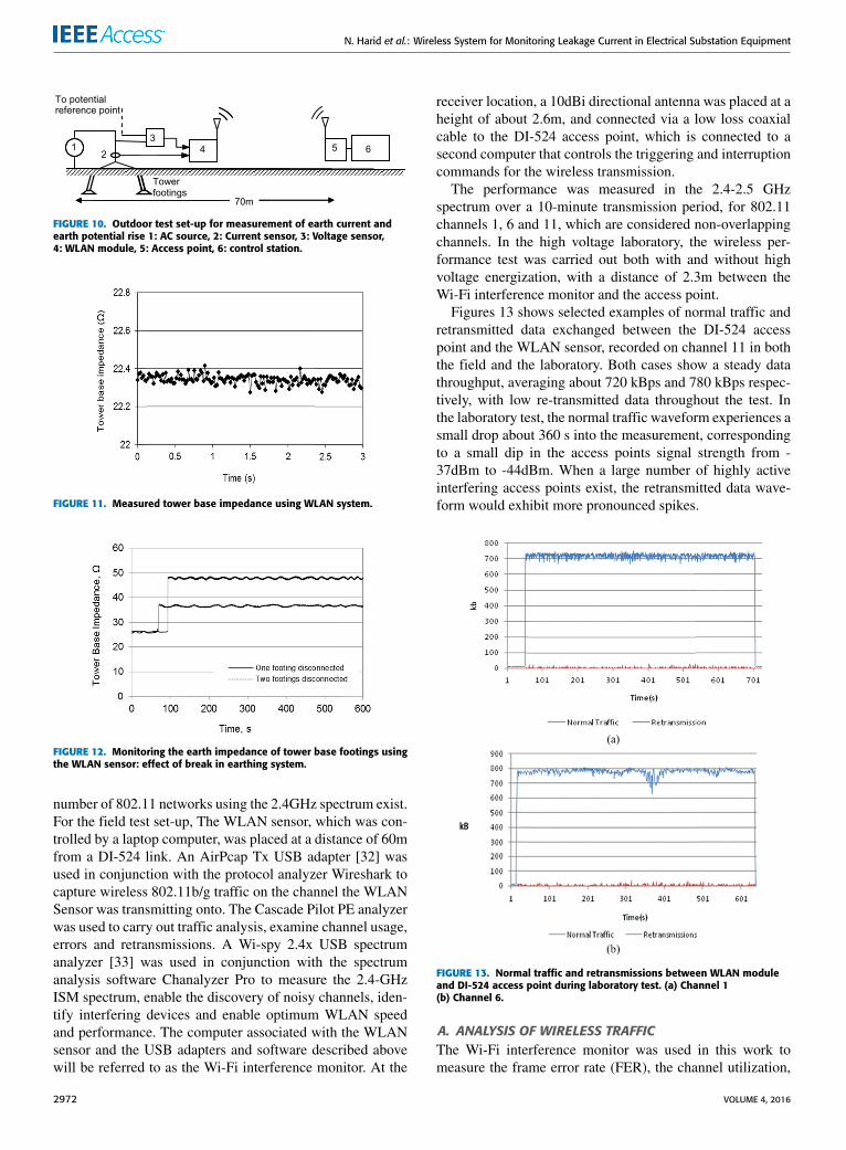
FIGURE 10. Outdoor test set-up for measurement of earth current andearth potential rise 1: AC source, 2: Current sensor, 3: Voltage sensor,4: WLAN module, 5: Access point, 6: control station.
FIGURE 11. Measured tower base impedance using WLAN system.
FIGURE 12. Monitoring the earth impedance of tower base footings usingthe WLAN sensor: effect of break in earthing system.
number of 802.11 networks using the 2.4GHz spectrum exist.For the field test set-up, The WLAN sensor, which was con-trolled by a laptop computer, was placed at a distance of 60mfrom a DI-524 link. An AirPcap Tx USB adapter [32] wasused in conjunction with the protocol analyzer Wireshark tocapture wireless 802.11b/g traffic on the channel the WLANSensor was transmitting onto. The Cascade Pilot PE analyzerwas used to carry out traffic analysis, examine channel usage,errors and retransmissions. A Wi-spy 2.4x USB spectrumanalyzer [33] was used in conjunction with the spectrumanalysis software Chanalyzer Pro to measure the 2.4-GHzISM spectrum, enable the discovery of noisy channels, iden-tify interfering devices and enable optimum WLAN speedand performance. The computer associated with the WLANsensor and the USB adapters and software described abovewill be referred to as the Wi-Fi interference monitor. At the
receiver location, a 10dBi directional antenna was placed at aheight of about 2.6m, and connected via a low loss coaxialcable to the DI-524 access point, which is connected to asecond computer that controls the triggering and interruptioncommands for the wireless transmission.
The performance was measured in the 2.4-2.5 GHzspectrum over a 10-minute transmission period, for 802.11channels 1, 6 and 11, which are considered non-overlappingchannels. In the high voltage laboratory, the wireless per-formance test was carried out both with and without highvoltage energization, with a distance of 2.3m between theWi-Fi interference monitor and the access point.
Figures 13 shows selected examples of normal traffic andretransmitted data exchanged between the DI-524 accesspoint and the WLAN sensor, recorded on channel 11 in boththe field and the laboratory. Both cases show a steady datathroughput, averaging about 720 kBps and 780 kBps respec-tively, with low re-transmitted data throughout the test. Inthe laboratory test, the normal traffic waveform experiences asmall drop about 360 s into the measurement, correspondingto a small dip in the access points signal strength from -37dBm to -44dBm. When a large number of highly activeinterfering access points exist, the retransmitted data wave-form would exhibit more pronounced spikes.
FIGURE 13. Normal traffic and retransmissions between WLAN moduleand DI-524 access point during laboratory test. (a) Channel 1(b) Channel 6.
A. ANALYSIS OF WIRELESS TRAFFICThe Wi-Fi interference monitor was used in this work tomeasure the frame error rate (FER), the channel utilization,
2972 VOLUME 4, 2016

N. Harid et al.: Wireless System for Monitoring Leakage Current in Electrical Substation Equipment
the number of access points and the total transmitted packets.The field tests, used as a benchmark, show a low FER forall three channels used. The analysis of the WLAN perfor-mance test results is summarized in Table 2. The differencesin magnitude of the FERs for the three channels used, islargely affected by the amount of wireless data transmittedby external access points and stations. The more externalwireless data is transmitted, the higher is the FER. In the high-voltage laboratory test, the WLAN system suffers the highestFER on channel 6 comparedwith other channels. The channelutilization is derived from a variable used by the WI-Spyanalysis software to evaluate the usage of an 802.11 channelover a period of time, and which measures how much RFactivity is affecting the channel. It is weighted so that signalsnear the center of the channel have a greater effect on theutilization score. It can be seen that the channel utilizationduring the laboratory test where more RF activity is presentis higher than that measured during the field test. The ‘accesspoints detected’ show all the access points identified duringthe entire 2.4GHz spectrum measurement period, and thevalues shown include the DI-524 access point used during thetest. As expected, a much larger number of access points withequally large transmitted packets were detected in the high-voltage laboratory test, which affects the FER accordingly.
TABLE 2. Traffic data between WLAN sensor and access point duringperformance tests.
There was no evidence to suggest that interferenceproduced by energized high voltage equipment affects thewireless performance of the WLAN sensor. The 2.4-2.5GHzfrequency content during the high voltage insulator testscontains no signals other than 802.11 detected accesspoints.
B. WIRELESS TRANSMISSION RATETable 3 shows the percentage of data transmitted at eachtransmission rate on channels 1, 6 and 11 measured by theWi-Fi interferencemonitor. On channels 1 and 11, while mostof the data used the highest possible 802.11 transmissionrate, a significant portion of the data exchanged between theWLAN module and access point has taken place at a rate of48 Mbps or lower. The rate adaptation is more severe duringthe test on channel 6 compared to those on channels 1 and 11.This is an indication that a higher gain antenna for theWLANmodule or the access point or both, would be advantageous.A low signal strength has the effect of dropping the wireless
TABLE 3. Percentage of data transmitted at each transmission rate onchannels 1, 6 and 11.
data transmission rate. This causes an increase in the receiv-ing sensitivity in both the WLAN module and access point.
V. CONCLUSIONThis paper has demonstrated the feasibility of a novel wirelesscondition monitoring system for application in high voltageelectrical substations. The system can be used as a standalonedevice or part of a multi-sensor network to measure leak-age current and voltage in a variety of equipment. It canbe configured to provide continuous data acquisitionat 80 kHz sampling rate on two channels and monitor specificquantities such as leakage current peak and r.m.s values,power dissipated, and accumulated energy at regular timeintervals. It has been successfully tested in three differentmonitoring applications: (A) for monitoring the leakage cur-rent of a surge arrester, (B) monitoring the surface conductioncurrent of polluted insulators and (C) monitoring the earthcurrent flowing through the footings of a high-voltage tower.The measured results were validated against those measureddirectly using a wired data acquisition card, and showedexcellent agreement. The effect of high-frequency interfer-ence signals generated by electrical discharges on the perfor-mance of the device was examined. Comparative tests werealso performed to determine the wireless sensor immunityto interference within a high voltage laboratory environmentand in an outdoor test facility. Analysis of wireless trafficmeasurements confirm that no interferences which mightaffect 802.11 networks are emitted from high voltage sources.Further work is required to improve accuracy, account fortransmission delays, and extend the application to multiplesensors.
REFERENCES[1] IEEE Standard for SCADA and Automation Systems,
IEEE Standard C37.1-2007, 2007.[2] L. A. Basile, S. Riendeau, H. Bertrand, and J. Béland, ‘‘The deployment of
wireless networks in high voltage substations: A feasibility study,’’ inProc.IEEE Elect. Power Energy Conf. (EPEC), London, ON, Canada, Oct. 2012,pp. 46–50.
[3] F. Cleveland, ‘‘Use of wireless data communications in power sys-tem operations,’’ in Proc. IEEE PES Power Syst. Conf. Expo. (PSCE),Oct./Nov. 2006, pp. 631–640.
[4] Y. Wang, F. A. M. Mir, and W. H. Siew, ‘‘Digital wireless data acquisitionsystem for measurement in high voltage substations,’’ in Proc. IEEE PowerEng. Soc. General Meeting, Jun. 2006, pp. 1–6.
VOLUME 4, 2016 2973

N. Harid et al.: Wireless System for Monitoring Leakage Current in Electrical Substation Equipment
[5] P. C. Baker, M. D. Judd, and S. D. J. McArthur, ‘‘A frequency-based RFpartial discharge detector for low-power wireless sensing,’’ IEEE Trans.Dielectr. Electr. Insul., vol. 17, no. 1, pp. 133–140, Feb. 2010.
[6] E. C. T. Macedo, J. G. Alira, E. G. Costa, andM. J. Maia, ‘‘Wireless sensornetwork applied to ZnO surge arrester,’’ in Proc. Int. Symp. High VoltageEng., Hanover, Germany, 2011, p. 396.
[7] R.Moghe, A. R. Iyer, F. C. Lambert, andD.M.Divan, ‘‘A low-cost wirelessvoltage sensor for monitoring MV/HV utility assets,’’ IEEE Trans. SmartGrid, vol. 5, no. 4, pp. 2002–2009, Jul. 2014.
[8] L. Juan, J. Shaohua,W. Yirong, andW. Hui, ‘‘Online insulation monitoringsystem of high-voltage capacitive substation equipment based on WSN,’’in Proc. China Int. Conf. Electr. Distrib. (CICED), Sep. 2010, pp. 1–6.
[9] X.Wang et al., ‘‘ Reliability test of using 802.11b technology in switchgearfor measurement and control,’’ in Proc. Int. Conf. Power Syst. Technol.,Oct. 2006, pp. 1–6.
[10] P. P. Parikh, T. S. Sidhu, and A. Shami, ‘‘A comprehensive investiga-tion of wireless LAN for IEC 61850-based smart distribution substationapplications,’’ IEEE Trans. Ind. Informat., vol. 9, no. 3, pp. 1466–1476,Aug. 2013.
[11] A. Abdrabou and A. M. Gaouda, ‘‘Uninterrupted wireless data transfer forsmart grids in the presence of high power transients,’’ IEEE Syst. J., vol. 9,no. 2, pp. 567–577, Jun. 2015.
[12] Q. Shan et al., ‘‘Laboratory assessment of WLAN performance degra-dation in the presence of impulsive noise,’’ in Proc. Int. Wireless Com-mun. Mobile Comput. Conf. (IWCMC), Crete Island, Greece, Aug. 2008,pp. 859–863.
[13] A. C. Bogias, N. Harid, A. Haddad, and H. Griffiths, ‘‘Wireless dataacquisition system for high voltage substations,’’ in Proc. 16th Int. Symp.High-Voltage Eng., Cape Town, South Africa, 2009, pp. 1–5.
[14] N. Harid, ‘‘A solar-powered wireless data acquisition system for monitor-ing electrical substations,’’ in Recent Advances in Circuits, Communica-tions and Signal Processing, A. Said, C. H. H. Tang, and S. Oprisan, Eds.WSEAS Press, 2013, p. 23.
[15] A. C. Bogias, ‘‘Awireless 802.11 conditionmonitoring sensor for electricalsubstation environments,’’ Ph.D. dissertation, School Eng., Cardiff Univ.,Wales, U.K., 2012.
[16] V. Raghunathan, A. Kansal, J. Hsu, J. Friedman, and M. Srivastava,‘‘Design considerations for solar energy harvesting wireless embeddedsystems,’’ in Proc. 4th Int. Symp. Inf. Process. Sensor Netw. (IPSN),Apr. 2005, pp. 457–462.
[17] D. Dondi, A. Bertacchini, D. Brunelli, L. Larcher, and L. Benini, ‘‘Mod-eling and optimization of a solar energy harvester system for self-poweredwireless sensor networks,’’ IEEE Trans. Ind. Electron., vol. 55, no. 7,pp. 2759–2766, Jul. 2008.
[18] Y. Li, H. Yu, B. Su, and Y. Shang, ‘‘Hybrid micropower source forwireless sensor network,’’ IEEE Sensors J., vol. 8, no. 6, pp. 678–681,Jun. 2008.
[19] C. Alippi and C. Galperti, ‘‘An adaptive system for optimal solar energyharvesting in wireless sensor network nodes,’’ IEEE Trans. Circuits Syst. I,Reg. Papers, vol. 55, no. 6, pp. 1742–1750, Jul. 2008.
[20] J. W. Kimball, B. T. Kuhn, and R. S. Balog, ‘‘A system design approach forunattended solar energy harvesting supply,’’ IEEE Trans. Power Electron.,vol. 24, no. 4, pp. 952–962, Apr. 2009.
[21] Surge Arresters- Metal-Oxide Surge Arresters Without Gaps for A.C. Sys-tems, document BS EN 60099-4, 2004.
[22] IEEE Guide for the Application of Metal Oxide Surge Arresters forAlternating-Current Systems, IEEE Standard C62.22-1, 1991.
[23] J. Lundquist, L. Stenstrom, A. Schei, and B. Hansen, ‘‘New methodfor measurement of the resistive leakage currents of metal-oxide surgearresters in service,’’ IEEE Trans. Power Del., vol. 5, no. 4, pp. 1811–1822,Oct. 1990.
[24] C. Heinrich and V. Hinrichsen, ‘‘Diagnostics and monitoring of metal-oxide surge arresters in high-voltage networks-comparison of existing andnewly developed procedures,’’ IEEE Trans. Power Del., vol. 16, no. 1,pp. 138–143, Jan. 2001.
[25] ABB EXCOUNT-II User’s Manual, document 1HSA 801 080-15 Edition3.2, 2010-03. 2010. [Online]. Available: http://new.abb.com/high-voltage/surge-arresters/high-voltage-arresters/surge-counters-and-monitors-for-surge-arresters-accessories/excount-ii
[26] Doble Lemke LCM 500 Leakage Current Monitor, accessed on Jun. 16,2016. [Online]. Available: http://www.doble.com/product/lcm500/
[27] E. Fontana, S. C. Oliveira, F. J. M. M. Cavalcanti, R. B. Lima,J. F. Martins-Filho, and E. Meneses-Pacheco, ‘‘Novel sensor systemfor leakage current detection on insulator strings of overhead transmis-sion lines,’’ IEEE Trans. Power Del., vol. 21, no. 4, pp. 2064–2070,Oct. 2006.
[28] S. Kurihara et al., ‘‘Construction of remote monitoring system for separa-tive measurement of leakage current of outdoor insulators,’’ in Proc. IEEE7th Int. Conf. Properties Appl. Dielectr. Mater., vol. 1. Nagoya, Japan,2003, pp. 401–404.
[29] S. Shihab, V. Melik, L. Zhou, G. Melik, and N. Alame, ‘‘On-line pollu-tion leakage current monitoring system,’’ in Proc. 4th Int. Conf. Prop-erties Appl. Dielectr. Mater., vol. 2. Brisbane, QLD, Australia, 1994,pp. 538–541.
[30] Artificial Pollution Tests on High-Voltage Insulators to be Used on ACSystems, document BSEN 60507, British Standards Institution, 1993.
[31] D. Guo, U. Hauser-Ehninger, H. Griffiths, A. Haddad, A. Ainsley, F.Ainslie and D. Frame, ‘‘A technique for the continuous condition monitor-ing of substation earthing systems,’’ in Proc. 15th Int. Symp. High VoltageEng. (ISH), Ljubljana, Slovenia, Aug. 2007, pp. 1–6, paper T2-445.
[32] Riverbed Technology, San Francisco, CA, USA. (2010).Riverbed AirPCap Datasheet. [Online]. Available: www.riverbed.com/document/fpo/DataSheet-Riverbed-AirPcap.pdf
[33] MetaGeek Tech. Ltd., Canada. (2016). Wy-Spy 2.4x Datasheet. [Online].Available: http://www.wispy.ca/wyspi24x.php
N. HARID (M’13) received the Ph.D. degreein electrical engineering from the Universityof Wales, Cardiff, U.K. He was an AssociateProfessor for several years before joining theHigh-Voltage Energy Systems Group, Cardiff Univer-sity, Cardiff, in 2001, as a Senior Researcher andSenior Lecturer. In 2013, he joined the PetroleumInstitute, AbuDhabi, where he is an Associate Pro-fessor of Electric Power and High-Voltage Engi-neering. He has authored or co-authored over 100
publications in his areas of research. His main research interests are inearthing systems, insulation systems, transients, breakdown phenomena, andmonitoring of high-voltage plant. He is a member of the IET and a fellow ofthe Higher Education Academy and served as a member of the BSI GEL/81Standard Committee on Lightning Protection.
A. C. BOGIAS received the B.Eng. degree in electrical and electronicengineering in 2004, and the Ph.D. degree from Cardiff University in 2012.
H. GRIFFITHS (M’15) received the B.Sc. degreein 1982, and received the Ph.D. degree fromCardiff University, U.K. From 1983 to 1990, hewas with the South Wales Electricity Board andthe Central Electricity Generating Board, where hewas an Engineer in distribution and transmissionsystem design. In 1990, he was appointed as a Lec-turing StaffMember with Cardiff University. Since2015, he has been a Professor of Power systemsand High-Voltage Engineering with the Petroleum
Institute, Abu Dhabi, prior to that with Cardiff University. His researchinterests include earthing systems and transients. He is currently a memberof British Standard Institution Committees BSI PEL/99 (HV ac substations),the Chair of BSI GEL/600 (earthing), and a member of CENELEC TC99XWG1, Earthing of Power Installations exceeding 1-kV ac, and the IECCommittee TC99/MT4-IEC 61936 Power Installations exceeding 1-kV ac.He is a Chartered Engineer and a member of the IET.
2974 VOLUME 4, 2016

N. Harid et al.: Wireless System for Monitoring Leakage Current in Electrical Substation Equipment
S. ROBSON (M’13) received theM.Eng. degree in2007 and the Ph.D. degree in 2012. In 2013, he wasappointed as Lecturer in Electrical Engineeringwith Cardiff University. His main research inter-ests are power line communication, fault location,condition monitoring, and simulation of transientson electrical networks.
A. HADDAD (M’13) received the degree ofIngénieur d’État in electrical engineering in1985 and the Ph.D. degree in high-voltageengineering in 1990. He is currently a Pro-fessor of Electrical Engineering with CardiffUniversity with responsibility for research inhigh-voltage engineering. He has authored an IET-Power Series Book entitled Advances in High-Voltage Engineering. His research interests are inovervoltage protection, insulation systems, insula-
tion coordination, and earthing of electrical energy systems. He is a memberof CIGREWorking Groups and a member of the BSI PEL1/2, the IEC TC37,and the IEC ACTAD committees. He serves on the scientific committees ofseveral international conferences. He is a fellow of the IET and the LearnedSociety of Wales.
VOLUME 4, 2016 2975