aalborg universitet passivity-based coordinated control
TRANSCRIPT

Aalborg Universitet
Passivity-based coordinated control for islanded AC microgrid
Gui, Yonghao; Wei, Baoze; Li, Mingshen; Guerrero, Josep M.; Vasquez, Juan C.
Published in:Applied Energy
DOI (link to publication from Publisher):10.1016/j.apenergy.2018.07.115
Publication date:2018
Document VersionEarly version, also known as pre-print
Link to publication from Aalborg University
Citation for published version (APA):Gui, Y., Wei, B., Li, M., Guerrero, J. M., & Vasquez, J. C. (2018). Passivity-based coordinated control forislanded AC microgrid. Applied Energy, 229, 551-561. https://doi.org/10.1016/j.apenergy.2018.07.115
General rightsCopyright and moral rights for the publications made accessible in the public portal are retained by the authors and/or other copyright ownersand it is a condition of accessing publications that users recognise and abide by the legal requirements associated with these rights.
- Users may download and print one copy of any publication from the public portal for the purpose of private study or research. - You may not further distribute the material or use it for any profit-making activity or commercial gain - You may freely distribute the URL identifying the publication in the public portal -
Take down policyIf you believe that this document breaches copyright please contact us at [email protected] providing details, and we will remove access tothe work immediately and investigate your claim.
Downloaded from vbn.aau.dk on: January 25, 2022

Aalborg Universitet
Passivity-Based Coordinated Control for Islanded AC Microgrid
Gui, Yonghao; Wei, Baoze; Li, Mingshen; Guerrero, Josep M.; Quintero, Juan CarlosVasquezPublished in:Applied Energy
Publication date:2018
Document VersionEarly version, also known as pre-print
Link to publication from Aalborg University
Citation for published version (APA):Gui, Y., Wei, B., Li, M., Guerrero, J. M., & Quintero, J. C. V. (2018). Passivity-Based Coordinated Control forIslanded AC Microgrid. Applied Energy, 229, 551-561.
General rightsCopyright and moral rights for the publications made accessible in the public portal are retained by the authors and/or other copyright ownersand it is a condition of accessing publications that users recognise and abide by the legal requirements associated with these rights.
? Users may download and print one copy of any publication from the public portal for the purpose of private study or research. ? You may not further distribute the material or use it for any profit-making activity or commercial gain ? You may freely distribute the URL identifying the publication in the public portal ?
Take down policyIf you believe that this document breaches copyright please contact us at [email protected] providing details, and we will remove access tothe work immediately and investigate your claim.
Downloaded from vbn.aau.dk on: November 16, 2018

Passivity-Based Coordinated Control for Islanded ACMicrogrid
Yonghao Gui1, Baoze Wei, Mingshen Li, Josep M. Guerrero, Juan C. Vasquez
Department of Energy Technology, Aalborg University, 9220 Aalborg, Denmark
Declarations of interest: none
Abstract
A novel passivity-based coordinated control strategy is proposed for an islanded AC
microgrid including renewable energy source and energy storage system units. The
main advantage is that the proposed coordinated control strategy manages the micro-
grid without using a phase-locked loop system. In the microgrid, the energy storage
system supports the voltage of the microgrid, and the renewable energy sources inject
their maximum power to the microgrid in the normal operation. For the energy stor-
age system, we use a proportional-resonant controller, and for the renewable energy
sources, we use a voltage modulated direct power control method, which has not only
a good tracking performance but also a good steady-state behavior. Another advantage
of the proposed method is that the asymptotical stability of the whole microgrid can be
guaranteed by using the passivity principle when the heterogeneous renewable energy
sources are integrated into the microgrid. To validate the proposed coordinated con-
trol law, we use a microgrid consisting of one energy storage system, one wind turbine,
one photovoltaic and two controllable loads. Simulation results show that the plug-and-
play capability of the wind turbine and photovoltaic in the microgrid is enhanced when
comparing with the conventional vector current control method with a phase-locked
loop system. Moreover, the voltage and frequency of the microgrid are recovered to its
nominal value by the energy storage system with the proposed method as well. Finally,
experimental verification of the proposed coordinated control algorithm is performed
1Email; [email protected].
Preprint submitted to Journal of Applied Energy August 2, 2018

on a 10 kW microgrid system. The experimental results match the simulation ones as
well.
Keywords: Coordinated control, islanded AC microgrid, renewable energy source,
energy storage system, passivity.
1. Introduction
Nowadays, a revolution of the world energy system is taking place to a low car-
bon, green, and sustainable one [1]. It introduces new network topologies, the new
components, and new design and operation strategies [2]. The wind turbines (WTs),
photovoltaic (PV), biomass, tidal power, and hydro are the most important sources in
renewable energy resources (RESs) to mitigate greenhouse gas emissions and provide
clean energy for sustainable development [3]. Due to the fast development of such
RESs, the large-scale RESs have been widely integrated into power distribution sys-
tems [4]. However, the volatile and intermittent nature of WT and PV sources may
cause serious problems regarding stability and reliability [5]. As the next generation of
power grids, the smart power grids require an intelligent strategy to integrate a large
number of RESs into a utility grid as a microgrid for reducing system uncertainties and
improving performance [6].
Microgrids operate not only in a grid-connected mode to exchange power with the
main grid [7], but also in the islanded mode to support local loads when the connec-
tion to grid fails [8]. With the rapid development of power converters, the RESs such
as PV and WT systems have been the main distributed generation sources in micro-
grids [9]. Consequently, the microgrid should be able to overcome the volatile and
intermittent nature of RESs [10]. Energy storage system (ESS) is considered as an es-
sential and effective solution to enhance the flexibility and controllability not only in
specific RESs [11], but also in the microgrid [12]. Hence, the coordinated control is
required to guarantee stored energy balance among ESSs and RESs to enhance the
stability and reliability of the microgrid system [13].
This coordinated problem has been addressed by centralized control and decentral-
ized control concerning the communication links [14]. In centralized control, as a cru-
2

cial element, the communication channels can enhance the stability of microgrid [15].
A communication based adaptive droop control for ESSs in a microgrid is proposed to
deliver more power regarding its higher state [16]. A coordinated control strategy for
state of charge (SoC) balancing in a microgrid has been proposed by combing commu-
nication technology with hierarchical control in [17]. However, these control methods
will not stabilize the system if communication network occurs failure. Coordinated
and integrated control is proposed for PV and battery storage systems regarding V-f
(or P-Q) droop control, maximum power point tracking (MPPT) control, and energy
storage charging and discharging controls [18]. However, it needs a central control
system. In [19], centralized coordinated control is employed for equalizing the SoC,
even for distributed ESSs with different capacities. However, the drawback is that the
overall system will lose coordination when a single point failure occurs in one of the
communication links. Multi-master-slave-based control has been proposed to provide
rapid load sharing considering distant groups while using the Conservative Power The-
ory [20]. Sun et al. proposed a power sharing unit based on the adaptive backstepping
sliding mode control to achieve the coordinated power sharing in a hybrid microgrid
structure [21]. However, there is a tradeoff between synchronization and power-sharing
accuracy for the method. Moreover, Arcos-Aviles et al. proposed a fuzzy logic-based
control strategy to deal with the problem of minimization of fluctuations and power
peaks while exchanging energy with the main grid [22]. However, it does not consider
the voltage and frequency regulation problem.
It is rapidly changing control and operation of microgrids from a centralized fash-
ion to a decentralized one [23]. In the decentralized control of microgrids, DG units
are required to share the total load demand in microgrids based on their power capac-
ities, preferably without communication links [24]. Decentralized coordinated control
for balancing discharge rate of ESSs in an islanded microgrid is an effective method to
prevent overcurrent and unintentional outage of RES units, and to provide fast response
and large stability margin [25]. Another decentralized control method is proposed by
detection of load change time in the microgrid [26]. In [27], autonomous real power
control strategy is proposed to realize decentralized power management, which relies
on local controllers without external communication links. Independent control is im-
3

plemented in each unit using multi-loop controllers to autonomously supply power only
during peak load periods and keep power balance [28]. However, the control conditions
are based on the PV system, while the multiple RESs are still not considered. In [29],
coordinated control strategy is investigated to control the power of islanded units flexi-
bly by applying smooth switching droop control. However, it needs a complex compu-
tation and additional microgrid management for ensuring reliable operation. Recently,
some distributed control methods are also proposed to enhance the performance of
the microgrids. A distributed generation control method is proposed for accurate real
power sharing and self-frequency recovery [30]. Xu and Sun propose an adaptive virtual
impedance control to obtain an improved real/reactive power sharing [31]. Moreover,
distributed cooperative control using feedback linearization [32], distributed-averaging
proportional–integral controller [33], dynamic consensus algorithm [34], droop-free
distributed method [35], fuzzy Q-learning for multi-agent method [36], and consensus-
based distributed coordination approach [37] are proposed to achieve bounded voltage
and accurate reactive power sharing in microgrids.
The aforementioned methods use a phase-locked loop (PLL) for synchronization
when RESs are integrated into the existing microgrids. Moreover, stability analysis of
the microgrids will become complex when the heterogeneous RESs are integrated. To
deal with these problems, in this paper, a novel coordinated control strategy applied to
RES/ESS units is proposed in islanded microgrids without using PLL. The ESS is oper-
ating to support the voltage and frequency in the microgrid, and the RESs are operating
to inject their maximum power to the microgrid. For the ESS, it uses a conventional
proportional-resonant (PR) controller [38], and for the RES, we use a voltage mod-
ulated direct power control (VM-DPC), which has not only a good tracking but also
steady-state performances [39]. One of the objective of the paper is that to remove the
synchronization process to improve the plug-and-play capability of RESs. The VM-
DPC enhances the plug-and-play capability of RESs since they are integrated into the
existing microgrids without using the PLL. It means that there is no synchronization
process, and we can expect the improved performance of the plug-and-play capability
of RESs.
Another objective is that the stability of the microgrids is to be guaranteed when
4

the heterogeneous RESs are integrated into the microgrid. To ensure the stability of
the microgrid, we use the passivity property, which has an advantage that if a group
of passive sub-systems is connected through paralleling or feedback, the whole system
is also stable and passive [40]. That is if each RES plugs-in to the whole microgrid
and satisfies passivity, the asymptotical stability of the microgrid can be guaranteed by
using the passivation [41]. Hence, we use the port-controlled Hamiltonian (PCH) for
RESs to get the passivity properties when the VM-DPC is used. To validate the pro-
posed coordinated control law, we use a microgrid consisting of one ESS, one WT, one
PV and controllable loads. Simulation and experiment results show that the islanded
microgrid is operating well and the plug-and-play capability of the WT and PV is en-
hanced. Compare to the conventional vector current control method with a PLL system,
the proposed control strategy shows an improved performance when the RESs are con-
nected to the microgrid in the simulation results. Moreover, the voltage and frequency
of the microgrid could be recovered to its nominal value by the ESS with the proposed
control strategy as well. In the future, we will design a secondary controller for this
coordinated control architecture with consideration of SoC for the ESS.
The rest of the paper is organized as follows. In Section 2, the conventional PR con-
troller and the VM-DPC are briefly introduced. Section 3 presents the stability analy-
sis for microgrids including RESs. Section 4 shows the case studies through MAT-
LAB/Simulink, Simscape Power Systems, and we also validate the proposed method
by using a 10 kW microgrid system in Section 5. Finally, the conclusions are given in
Section 6.
2. Review of PR and VM-DPC
In this Section, we briefly introduce PR and VM-DPC controllers. The PR con-
troller is used for the ESS to fix the voltage and frequency in the microgrid, and the
VM-DPC is used for RESs, which will inject its maximum power to the microgrid.
2.1. PR controller
For controlling an AC signal, the PR controller is an effective method to track the
reference without steady-state error comparing with PI control. The transfer function
5

Islanded Mode
AC
DC
AC Microgrid Commercial Buildingsngs
Figure 1: Architecture of an islanded AC microgrid
of the ideal PR controller can be expressed as follows:
G(s) = KP +KRs
s2 +ω20, (1)
where ω0 is the angular frequency. KP and KR are the controller gains. The controller
has an infinite gain at the frequency ω0, and there is no phase shift and gain at other fre-
quency. KP is able to determine the dynamics of the system regarding bandwidth, phase
and gain margin [38]. Besides fundamental frequency compensation, the harmonic
compensation can be obtained by cascading several generalized integrators tuned to
resonate at the desired frequency. For example, the transfer control of harmonic com-
pensator designed to compensate the 3rd, 5th and 7th harmonics is given as follows:
Gh(s) = ∑h=3,5,7
Kihs
s2 +(ω0×h)2 , (2)
where Kih is the controller gain. Thus, the harmonic compensator works on both pos-
itive and negative sequences of the selected harmonic, which only reacts to the fre-
quency very close to the resonant frequency. The enhanced tracking performances are
employed widely for grid-connected inverter control. For the simplification, we use the
PR controller for the ESS to support the voltage for the microgrid as shown in Fig. 2.
The references of the voltage and frequency of the microgrid are given to the PR con-
troller of the ESS.
6

Current
PR+active
damping
Power
Calculator
Load
dcvav
bv
cv
,L bi
,L ci
aC bC cC
n
,C cv
,C bv
,C av
abcab
Li ab Cv ab
SVM
abcab
,L ai
,in cL
,in bL
.in aL,o aL
,o bL
,o cL
+
,o bi
,o ci
,o ai
dcV
2av
2bv
2cv
2obv
2oavaL
bL
cL2ocv
2obi
2oci
2oai
SVM
abcab
ab Voltage
Reference
Generator
vvvvv
abcab
-- + +MPPTMPPT
Strategies
VM-DPC
In PCH
(23)+(27)
Voltage
Resonant
Controller
-
*P
P
Switch
vvvv
ESS
DC
-lin
k
*
rmsV *f
*
Cv ab*
Li ab
*vab
*
2v ab RES1
RES2
Figure 2: Control block diagram of the passivity-based coordinated control for RESs and ESS.
Power
Calculator
Eq. (4)
dcV
av
bv
cv
obv
oavaL
bL
cLocv
obi
oci
oai
SVM
abcab
+MPPT
Strategies
-
Switch
RE
S
*vab
abcab
vv
VM-DPC
Eq. (10)
1 1 2 2
T
K e K eé- ùë ûfbu
+
+
*u
Eq. (28)vmu
VM-DPC in PCH
ov ab
oi ab
Microgrid
*P
P
Figure 3: Controller block diagram of RES.
7

2.2. VM-DPC of RES
Fig. 2 shows that two RESs are connected to the microgrid through an inverter with
an L-filter. Considering a balanced grid voltage condition, the dynamics of line current
in α-β reference frame are represented as follows [42]:
vα = Rioα +Ldioα
dt+ voα ,
vβ = Rioβ +Ldioβ
dt+ voβ ,
(3)
where ioα , ioβ , vα , vβ , voα , and voβ represent the line currents, converter voltages,
and grid voltages in α − β frame, respectively. L and R are the filter inductance and
resistance, respectively. We define the instantaneous real and reactive powers as fol-
lows [43]:
P =32(voα ioα + voβ ioβ ),
Q =32(voβ ioα − voα ioβ ),
(4)
where P and Q are the instantaneous output real and reactive powers, respectively.
With consideration of a nondistorted grid, the dynamics of the instantaneous real and
reactive powers could be obtained based on the grid voltage variations as follows:
dPdt
=−RL
P−ωQ+3
2L(voα vα + voβ vβ −V 2
g ),
dQdt
= ωP− RL
Q+3
2L(voβ vα − voα vβ ),
(5)
where ω is the angular velocity of the voltage and Vg =√
v2oα + v2
oβ. Define two
states and two control inputs as x =[x1,x2
]T=[P,Q
]T∈ Xo ⊂ R2, u =
[u1,u2
]T=[
vα ,vβ
]T∈ Uo ⊂ R2, where Xo and Uo are the compact sets in the operating range.
Then, a continuous dynamic model of an RES in state-space is represented as follows:
x =
−RL x1−ωx2 +
32L (voα u1 + voβ u2−V 2
g )
ωx1− RL x2 +
32L (voβ u1− voα u2)
,y =
[x1 x2
]T.
(6)
We define a VM control inputs [44]:
uvm =
uvm1
uvm2
=
voα u1 + voβ u2
−voβ u1 + voα u2
. (7)
8

Consequently, the original system (6) can be rewritten as follows:
x =
−RL x1−ωx2 +
32L (uvm1−V 2
g )
ωx1− RL x2− 3
2L uvm2
. (8)
For tracking performance, we define an error vector such as
e := x∗− x =
e1
e2
=
x∗1− x1
x∗2− x2
, (9)
where x∗ =[x∗1 x∗2
]Tdenotes the reference.
Theorem 1. [45] Consider the system (8), if we take a control law such as
uvm =
uvm1
uvm2
=
V 2g + 2R
3 x1 +2Lω
3 x2 +ν1
2Lω
3 x1− 2R3 x2−ν2
, (10)
and ν1 and ν2 can be designed as follows:
ν1 = KP,pe1 +KP,i
∫ t
0e1(τ)dτ,
ν2 = KQ,pe2,+KQ,i
∫ t
0e2(τ)dτ,
(11)
where KP,p, KQ,p, KP,i, and KQ,i are the positive gains, then the errors globally expo-
nentially converge to zeros. ♦
Proof: We differentiate each output until at least one of the control inputs appears.y1
y2
=
−RL x1−ωx2 +
32L (uvm1−V 2
g )
ωx1− RL x2− 3
2L uvm2
. (12)
If, the control inputs uvm1 and uvm2 are taken as (10), then the output is
y1 = νP, y2 = νQ. (13)
To simplify the analysis, we assume that x∗1 = 0 and x∗2 = 0. Consequently, taking the
new control law as (11) gives us two simple decoupled error dynamics for real and
reactive powers.
e1 =−KP,pe1−KP,i
∫ t
0e1(τ)dτ,
e2 =−KQ,pe2−KQ,i
∫ t
0e2(τ)dτ.
(14)
It is obvious that the closed-loop system is globally exponentially stable. �
9

3. Stability Analysis
In this Section, we discuss the stability of the microgrid. The various methods of the
stability analysis for the microgrids have been researched [46]. In [47], a small-signal
model of a microgrid is studied. The stability of the DC microgrid is guaranteed by
using the passivation in [41]. In this paper, we guarantee the stability of the whole AC
microgrid via the passivity property, which has an advantage that the whole system is
stable and passive if a group of passive sub-systems is connected through paralleling or
feedback. At first, we briefly introduce a port-controlled Hamiltonian (PCH) system,
which satisfies passivity property [48]. Then, we use the PCH for RESs to get the
passivity property when the VM-DPC is applied to the RES.
3.1. Port-Controlled Hamiltonian (PCH) System
Let x∈Rn denotes the state vector and u∈Rm denotes the input. Consider a system
described in the state space as
x = f (x,u), (15)
where x ∈ X ⊂Rn is the state vector, and u ∈U ⊂Rm is the input. The function f (·, ·) :
X ×U → Rn is sufficiently smooth in the open connected set X . Suppose that (15)
satisfies a PCH system as follows:
x = (J−R)∂H(x)
∂x+G(u), (16)
where H is the Hamiltonian function given by
H(x) =12
xT Sx, S = ST � 0,
JT =−J, R=RT � 0.(17)
Here,� indicates positive definite, the matrices S and R are constant n×n matrices. R
indicates the dissipative forces in the system, J represents the conservative forces, and
G(u) represents the energy acquisition term [49, 50].
Assumption 1. Suppose that there exist signals ud(t) and xd(t) that satisfy the PCH
form (16):
xd = (J−R)∂H(xd)
∂xd +G(ud). (18)
10

♦
In this paper, we consider that the system dynamics are sufficiently smooth in the open
connected set X ., thus Assumption 1 is acceptable in this study.
Theorem 2. Suppose a system has the PCH form in (16) and has a reference trajectory
xd(t) that satisfies (18). If u = ud is applied to the system in (16), then the closed-loop
system is exponentially stable. Namely, limt→∞ x(t) = xd(t). ♦
Proof: Let x(t) ∈ X ⊂Rn be the trajectory of (16) corresponding to u = ud ∈U ⊂
R such that
x =(J(ud)−R
)∂H(x)
∂x+G(ud).
Although x(t) and xd(t) satisfy the same dynamics equations, but they are not the same
signals because their initial conditions could be different. By defining the error as e :=
xd− x, we obtain the following tracking error dynamics:
e = xd− x =(J(ud)−R
)∂H(e)
∂e .
Let us use H(e) as a Lyapunov function candidate, where H is defined in (17). The
total time derivative of H(e) is given by
H(e) = 12
(eT(
∂H(e)∂e
)+(
∂H(e)∂e
)Te)
=−eT STRSe.
Since S = ST � 0 and R� 0, the equilibrium point at the origin of the error dynamics
is globally exponentially stable. Hence, limt→∞ ‖ xd(t)− x(t) ‖= 0. �
Remark 1. x and xd have the same dynamics but may have different initial conditions.
ud could be obtained if we use the flatness property. However, to use the advantages
of the VM-DPC, the following analysis is addressed.
3.2. VM-DPC with PCH
In this study, the dynamics in (8) also satisfy the PCH form in (16). For the system
(8), if we take a Hamiltonian function such that
H(x) =12
xT Sx (19)
11

where S = I2, then the system in (8) is changed into the PCH form in (16) as follows:
x = (J−R)∂H(x)
∂x+G(u), (20)
where
J=
0 ω
−ω 0
,R=
RL 0
0 RL
,G(u) =
32L (uvm1−V 2
g )
32L uvm2
.Assumption 2. We define VM-DPC in (10) as u∗, suppose that using u∗, x converges
to x∗ that has a relationship with xd of (18) as follows:
xd− x∗ =
exp−λ1t(xd1− x1)
exp−λ2t(xd2− x2)
. (21)
where λ1,2 are the decay ratio of each state. ♦
Assumption 2 is acceptable in this study, since from Theorem 1, we conclude that the
closed loop system is globally exponentially stable. Regarding Assumptions 1 and 2,
we can get the relationship between the desired controller in (18), ud , and VM-DPC in
(10), u∗ = uvm, as follows:
δu1 = ud1−u∗1 =
3exp−λ1t
2L
(−λ1e1 +
RL
e1 +ωe2
),
δu2 = ud2−u∗2 =
3exp−λ2t
2L
(λ2e2−
RL
e2 +ωe1
),
(22)
where λ1 and λ2 are the decay ratio of e1 and e2, respectively. .
Assumption 3. Suppose that ∀x ∈ Xo, where Xo is operating range, there exist ∆1 and
∆2 that satisfy:
sup∀x∈Xo
e1 = ∆1, sup∀x∈Xo
e2 = ∆2. (23)
♦
Due to the rated power of converters and RESs, the powers generated from the RESs
to the microgrid are bounded. Moreover, the states are stabilized and regulated in the
operating range via the VM-DPC. Consequently, e and e are also be bounded with the
given reference. Consequently, Assumption 3 is acceptable in this study.
12

Theorem 3. Given dynamic system (8), suppose that the Assumptions 1 to 3 hold. If
the control input is designed with VM-DPC (10) and a new feedback such as
uvm = u∗+u f b, (24)
where u f b =[−κ1|e1|,κ2|e2|
]Twith κ1 ≥ λ1∆1 and κ2 ≥ λ2∆2, then the tracking error
of (8) based on the PCH form is exponentially stabilized. ♦
Proof: Let us consider a Lyapunov function candidate such as
V (e) =12
eT Se > 0. (25)
The derivative of (25) with respect to time results in
V (e) =12
(eT(
∂H(e)∂e
)+
(∂H(e)
∂e
)T
e
)=−eTRe+δu1e1 +δu2e2−κ1|e1|−κ2|e2|.
(26)
Using (22), (26) can be rewritten as follows:
V (e)≤−λ1 exp−λ1t e1e1−λ2 exp−λ2t e2e2−κ1|e1|−κ2|e2|
≤ −ε1|e1|− ε2|e2|< 0,(27)
where ε1 ≥ κ1−λ1∆1 and ε2 ≥ κ2−λ2∆2. Thus the tracking error of (8) in the PCH
form is exponentially stabilized. �
Finally, based on (7) and (24), the original control inputs are calculated.
vα =voα uvm1− voβ uvm2
V 2g
,
vβ =voβ uvm1 + voα uvm2
V 2g
.
(28)
Remark 2. To guarantee the passivity property of the ESS, we modified the PR con-
troller with active damping, which was designed in [51].
Fig. 3 shows the block diagram of the proposed method. In normal operation, RES
will generate its maximum power. Hence, we assume that RESs are operated in MPPT
13

Table 1: System parameters used in simulation
Parameter Symbol Value Unit
Nominal bus voltage V ∗rms 230 V
Nominal bus frequency f ∗ 50 Hz
Filter inductance of ESS Lin 1.8 mH
Filter capacitor of ESS C 9×3 µF
Output inductance of ESS Lo 1.8 mH
Filter inductance of PV & WT Lpv&Lwt 3.6 mH
mode in this study. Based on Theorem 3, the integrated RESs have the passivity prop-
erty. Consequently, the stability of the whole microgrid can be guaranteed by using the
passivity principle [40], i.e. the whole system including the ESS and RESs is asymp-
totically stable.
4. Simulation Results
To validate the proposed coordinated control method, we use MATLAB/Simulink,
Simscape Power Systems. The microgrid selected as a case study is modified from
the one discussed in [52], where a lab-scale prototype is used based a real microgrid
platform implemented in Shanghai [53]. The parameters of the tested system are listed
in Table 1. The ESS supports the bus voltage and frequency for the microgrid and the
WT and PV inject their MPPT powers to the microgrid, as shown in Fig. 4. The VSCs
of the ESS and the RESs are used through the switched model in Simscape Power
Systems library, and the proposed control strategy is implemented by using Simulink
library.
Fig. 5 describes the power tracking performance when the WT, PV, loads 1&2 are
connected to the microgrid. At first, the ESS generates and maintains the bus voltage
and frequency of the microgrid. At 0.2 s, the switch S1 is on, and the load 1 is con-
nected to the microgrid. At this time, only ESS injects the real power to the microgrid
to balance the generation and consumption. Suddenly, the switch S2 turns on at 0.51
s, and the WT is connected to the microgrid and generates 6 kW. For this connection,
14

Islanded Mode
AC
DC
wtP pvP essP
1lP 2lP
P
2S
1S
3S
4S
Figure 4: Electrical scheme used in the simulation.
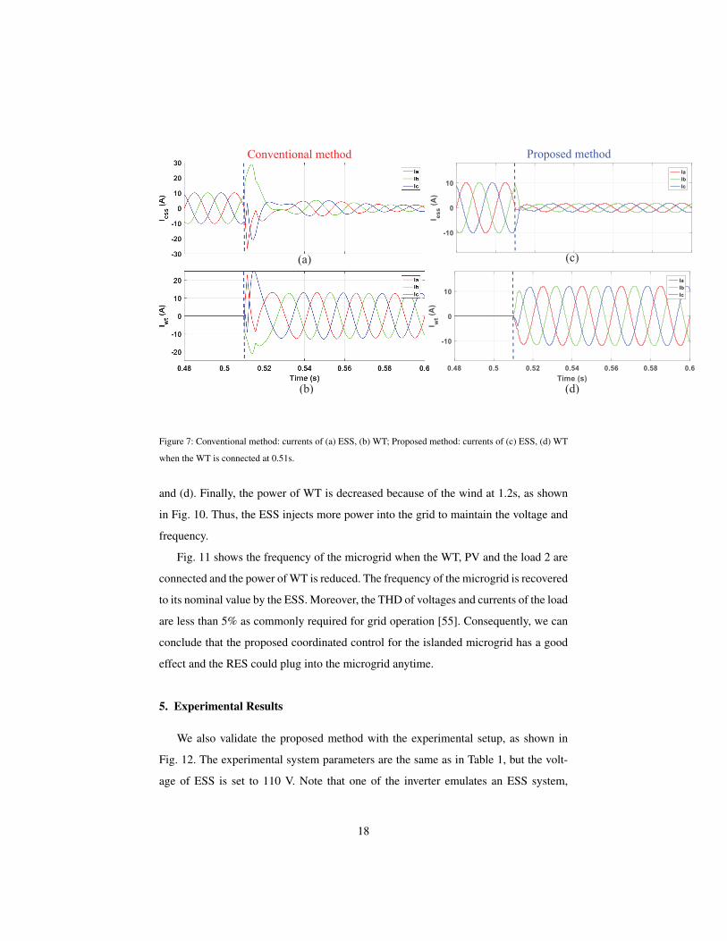
the WT does not require a synchronization process. Fig. 7(c) and (d) show the currents
of the ESS and WT at 0.51 s, and the WT is connected and injects the currents to the
microgrid simultaneously. The WT supports all the power consumed at the load and
the surplus power is flowing into the ESS for its charging, as shown in Fig. 5 (a). The
voltages and currents of the load 1 have a small overshoot and converge to their oper-
ating points in one cycle, as shown in Fig. 8(c) and (d). To compare the performance,
we use a conventional method, which uses a vector current control designed in the d–q
frame with a PLL system. Fig. 7(b) shows that the currents of WT with the conven-
tional method have a larger overshoot than those with the proposed method when the
WT is connected and injects the currents to the microgrid simultaneously, since there
is a synchronization process with the conventional method. The PLL system estimates
the phase angle of the grid voltage slowly due to the slow dynamics of the PLL system.
We can increase the bandwidth of the PLL system to improve the dynamic perfor-
mance. However, increasing the bandwidth of the PLL system will cause a unstable
phenomenon in a weak grid as discussed in [54]. Hence, we could not increase the
bandwidth too much. Such overshoot affects the currents and voltages of the load as
well, as shown in Fig. 8(a) and (b). Moreover, the protection system of the inverter may
15

(a) (b)
(c) (d)
discharging
chargingdischarging
Load 1 is
connected
Load 2 is
connected
PV is
connected
WT is
connected
Power of WT
is reduced
Figure 5: The performance of real power of the proposed coordinated control for the islanded AC microgrid:
(a) ESS, (b) WT, (c) load, (d) PV.
be activated due to the larger overshoot of the currents when doing some experimental
test.
After 0.2 s, the PV is suddenly connected to the microgrid and generates 4 kW.
For this connection, the power ripples in the microgrid are slightly increased, and the
real power of the load 1 has a slight overshoot, since the voltages and currents of the
load are affected by the connection of the PV as shown in Fig. 6. At this time, the PV
also does not require the synchronization process. The ESS absorbs the extra powers to
maintain the voltage and frequency in the microgrid. Moreover, at 1 s, another load (5
kW) is connected to the microgrid, and the total power of the RESs is equal to the total
power of the loads. Consequently, the ESS only supports the voltage and frequency in
the microgrid with 0 power regulation, as shown in Fig. 5 (a). Fig. 9 shows that the
voltages and currents converge to their operating points fast, but the connection of the
load 2 affects the WT and PV which have a slight undershoot, as shown in Figs. 5 (b)
16

(a)
(b)
load 1 is
connected
WT is
connected
PV is
connected
load 2 is
connected
WT is
decreased
Figure 6: Injected currents and voltages of the whole loads. (a) Currents, (b) voltages.
17
(c)
(d)
(a)
(b)
Proposed methodConventional method
Figure 7: Conventional method: currents of (a) ESS, (b) WT; Proposed method: currents of (c) ESS, (d) WT
when the WT is connected at 0.51s.
and (d). Finally, the power of WT is decreased because of the wind at 1.2s, as shown
in Fig. 10. Thus, the ESS injects more power into the grid to maintain the voltage and
frequency.
Fig. 11 shows the frequency of the microgrid when the WT, PV and the load 2 are
connected and the power of WT is reduced. The frequency of the microgrid is recovered
to its nominal value by the ESS. Moreover, the THD of voltages and currents of the load
are less than 5% as commonly required for grid operation [55]. Consequently, we can
conclude that the proposed coordinated control for the islanded microgrid has a good
effect and the RES could plug into the microgrid anytime.
5. Experimental Results
We also validate the proposed method with the experimental setup, as shown in
Fig. 12. The experimental system parameters are the same as in Table 1, but the volt-
age of ESS is set to 110 V. Note that one of the inverter emulates an ESS system,
18

(c)
(d)
(a)
(b)
Proposed methodConventional method
Figure 8: Performance of the load 1 when the WT is connected at 0.51s. Conventional method: (a) currents,
(b) voltages; Proposed method: (c) currents, (d) voltages.
(a)
(b)
Figure 9: Performance of the whole loads when the load 2 is connected to the microgrid. (a) Currents, (b)
voltages.
19

Figure 10: Currents of the WT when the power of WT is reduced at 1.2 s.
Load 2 is
connected
Power of WT
is reduced
WT is
connected PV is
connected
(a)
(b)
Figure 11: Frequency of the microgrid (a) when the WT and PV are connected; (b) when the load 2 is
connected and the WT is reduced.
20

dSPACE
ESS
Load
Switch
Controldesk
PV & wind
Figure 12: Experimental setup in the laboratory.
and the other two inverters emulate WT and PV, respectively. All the controllers are
implemented in the dSPACE 1006 system.
Fig. 13 shows the real power of the ESS and RESs. At first, the ESS supports
voltage and frequency to a three-phase load. At 1.85 s, the WT is connected and injects
0.7 kW power to the microgrid, as shown in Fig. 13. The ESS reduces its power to
keep the voltage of the load, as shown in Fig. 13 (a). At 2.85 s, the PV is connected and
injects 0.4 kW power to the microgrid, as shown in Fig. 13 (d), while the ESS absorbs
the power to keep the voltage of the loads, as shown in Fig. 13 (a) and Fig. 14 (c).
6. Conclusions
A novel coordinated control applied to renewable energy source and energy storage
system units was proposed to deal with the synchronization problem without phase-
locked loop system and stability issues in islanded microgrids . The energy storage
system using the conventional proportional resonant controller supports the voltage
and frequency of the microgrid, and the renewable energy sources are injecting their
maximum power to the microgrid in the normal operation by using the voltage modu-
lated direct power control, which enhances their plug-and-play capabilities since they
are integrated into the existing microgrids without using the phase-locked loop system.
21

discharging
charging
PV is connected
WT is connected
(c)
(a)
Time (s)
(b)
Pes
s(W
)P
wt(W
)P
pv
(W)
Figure 13: The experimental results of real power of the proposed coordinated control for the islanded
microgrid: (a) ESS, (b) WT, and (c) PV.
22

(b)
(d)
(a)
(c)
Figure 14: (a) Voltage of ESS and (b) current of WT when the WT is connected; (c) voltage of ESS and (d)
current of PV when the PV is connected.
23

Moreover, we used the passivity property to guarantee the stability of the microgrid.
Simulation and experimental results show that the islanded microgrid is operating well
and the plug-and-play capabilities of the renewable energy sources are enhanced when
comparing with the conventional method.
Acknowledgment
The authors would like to thank the anonymous reviewers and the Guest Editor
for their meticulous and constructive comments that helped improve the quality of this
paper.
References
[1] E. Mengelkamp, J. Garttner, K. Rock, S. Kessler, L. Orsini, C. Weinhardt, Design-
ing microgrid energy markets: A case study: The Brooklyn Microgrid, Applied
Energy 210 (2018) 870–880.
[2] J. Wu, J. Yan, H. Jia, N. Hatziargyriou, N. Djilali, H. Sun, et al., Integrated energy
systems, Applied Energy 167 (2016) 155–157.
[3] H. Hu, N. Xie, D. Fang, X. Zhang, The role of renewable energy consumption
and commercial services trade in carbon dioxide reduction: Evidence from 25
developing countries, Applied Energy 211 (2018) 1229–1244.
[4] M. F. Zia, E. Elbouchikhi, M. Benbouzid, Microgrids energy management sys-
tems: A critical review on methods, solutions, and prospects, Applied Energy 222
(2018) 1033 – 1055.
[5] D. I. Makrygiorgou, A. T. Alexandridis, Distributed stabilizing modular control
for stand-alone microgrids, Applied Energy 210 (2018) 925–935.
[6] C. Wang, J. Yan, C. Marnay, N. Djilali, E. Dahlquist, J. Wu, H. Jia, Distributed
energy and microgrids (DEM), Applied Energy 210 (2018) 685 – 689.
24

[7] J. M. Guerrero, J. C. Vasquez, J. Matas, L. G. De Vicuna, M. Castilla, Hierarchical
control of droop-controlled AC and DC microgrids—A general approach toward
standardization, IEEE Trans. Ind. Electron. 58 (1) (2011) 158–172.
[8] S. Riverso, M. Tucci, J. C. Vasquez, J. M. Guerrero, G. Ferrari-Trecate, Stabiliz-
ing plug-and-play regulators and secondary coordinated control for AC islanded
microgrids with bus-connected topology, Applied Energy 210 (2018) 914–924.
[9] L. H. Koh, P. Wang, F. H. Choo, K.-J. Tseng, Z. Gao, H. B. Puttgen, Operational
adequacy studies of a PV-based and energy storage stand-alone microgrid, IEEE
Trans. Power Syst. 30 (2) (2015) 892–900.
[10] M. Nehrir, C. Wang, K. Strunz, H. Aki, R. Ramakumar, J. Bing, Z. Miao,
Z. Salameh, A review of hybrid renewable/alternative energy systems for electric
power generation: Configurations, control, and applications, IEEE Trans. Sustain.
Energy 2 (4) (2011) 392–403.
[11] H. Zhao, Q. Wu, S. Hu, H. Xu, C. N. Rasmussen, Review of energy storage system
for wind power integration support, Applied Energy 137 (2015) 545–553.
[12] J. Wu, C. Zhang, Z. Chen, An online method for lithium-ion battery remaining
useful life estimation using importance sampling and neural networks, Applied
energy 173 (2016) 134–140.
[13] J. Hu, Y. Xu, K. W. Cheng, J. M. Guerrero, A model predictive control strategy
of PV-Battery microgrid under variable power generations and load conditions,
Applied Energy 221 (2018) 195–203.
[14] M. Ashabani, H. B. Gooi, J. M. Guerrero, Designing high-order power-source
synchronous current converters for islanded and grid-connected microgrids, Ap-
plied Energy 219 (2018) 370 – 384.
[15] W. Shi, X. Xie, C.-C. Chu, R. Gadh, Distributed optimal energy management in
microgrids, IEEE Trans. Smart Grid 6 (3) (2015) 1137–1146.
25

[16] X. Lu, K. Sun, J. M. Guerrero, J. C. Vasquez, L. Huang, State-of-charge balance
using adaptive droop control for distributed energy storage systems in DC micro-
grid applications, IEEE Trans. Ind. Electron. 61 (6) (2014) 2804–2815.
[17] T. Dragicevic, J. M. Guerrero, J. C. Vasquez, D. Skrlec, Supervisory control of
an adaptive-droop regulated DC microgrid with battery management capability,
IEEE Trans. Power Electron. 29 (2) (2014) 695–706.
[18] S. Adhikari, F. Li, Coordinated Vf and PQ control of solar photovoltaic genera-
tors with MPPT and battery storage in microgrids, IEEE Trans. Smart Grid 5 (3)
(2014) 1270–1281.
[19] N. L. Dıaz, A. C. Luna, J. C. Vasquez, J. M. Guerrero, Centralized control archi-
tecture for coordination of distributed renewable generation and energy storage in
islanded AC microgrids, IEEE Trans. Power Electron. 32 (7) (2017) 5202–5213.
[20] A. Mortezaei, M. Simoes, M. Savaghebi, J. Guerrero, A. Al-Durra, Cooperative
control of multi-master-slave islanded microgrid with power quality enhancement
based on conservative power theory, IEEE Trans. Smart Grid 9 (4) (2018) 2964–
2975. doi:10.1109/TSG.2016.2623673.
[21] Q. Sun, J. Zhou, J. M. Guerrero, H. Zhang, Hybrid three-phase/single-phase mi-
crogrid architecture with power management capabilities, IEEE Trans. Power
Electron. 30 (10) (2015) 5964–5977.
[22] D. Arcos-Aviles, J. Pascual, F. Guinjoan, L. Marroyo, P. Sanchis, M. P. Mari-
etta, Low complexity energy management strategy for grid profile smoothing of
a residential grid-connected microgrid using generation and demand forecasting,
Applied energy 205 (2017) 69–84.
[23] M. A. Zehir, A. Batman, M. A. Sonmez, A. Font, D. Tsiamitros, D. Stimoniaris,
T. Kollatou, M. Bagriyanik, A. Ozdemir, E. Dialynas, Impacts of microgrids with
renewables on secondary distribution networks, Applied energy 201 (2017) 308–
319.
26

[24] J. Li, R. Xiong, Q. Yang, F. Liang, M. Zhang, W. Yuan, Design/test of a hybrid en-
ergy storage system for primary frequency control using a dynamic droop method
in an isolated microgrid power system, Applied Energy 201 (2017) 257–269.
[25] Y. Karimi, H. Oraee, M. S. Golsorkhi, J. M. Guerrero, Decentralized method for
load sharing and power management in a PV/battery hybrid source islanded mi-
crogrid, IEEE Trans. Power Electron. 32 (5) (2017) 3525–3535.
[26] M. Kosari, S. H. Hosseinian, Decentralized reactive power sharing and frequency
restoration in islanded microgrid, IEEE Trans. Power Syst. 32 (4) (2017) 2901–
2912.
[27] D. Wu, F. Tang, T. Dragicevic, J. C. Vasquez, J. M. Guerrero, Autonomous ac-
tive power control for islanded AC microgrids with photovoltaic generation and
energy storage system, IEEE Trans. Energy Convers. 29 (4) (2014) 882–892.
[28] H. Mahmood, D. Michaelson, J. Jiang, Strategies for independent deployment
and autonomous control of PV and battery units in islanded microgrids, IEEE J.
Emerging Sel. Topics in Power Electron. 3 (3) (2015) 742–755.
[29] D. Wu, F. Tang, T. Dragicevic, J. C. Vasquez, J. M. Guerrero, A control archi-
tecture to coordinate renewable energy sources and energy storage systems in
islanded microgrids, IEEE Trans. Smart Grid 6 (3) (2015) 1156–1166.
[30] Y.-S. Kim, E.-S. Kim, S.-I. Moon, Distributed generation control method for ac-
tive power sharing and self-frequency recovery in an islanded microgrid, IEEE
Trans. Power Syst. 32 (1) (2017) 544–551.
[31] Y. Xu, H. Sun, Distributed finite-time convergence control of an islanded low-
voltage AC microgrid, IEEE Trans. Power Syst. 33 (3) (2018) 2339–2348. doi:
10.1109/TPWRS.2017.2743011.
[32] A. Bidram, A. Davoudi, F. L. Lewis, J. M. Guerrero, Distributed cooperative sec-
ondary control of microgrids using feedback linearization, IEEE Trans. Power
Syst. 28 (3) (2013) 3462–3470.
27

[33] J. W. Simpson-Porco, Q. Shafiee, F. Dorfler, J. C. Vasquez, J. M. Guerrero,
F. Bullo, Secondary frequency and voltage control of islanded microgrids via dis-
tributed averaging, IEEE Trans. Ind. Electron. 62 (11) (2015) 7025–7038.
[34] L. Meng et al., Distributed voltage unbalance compensation in islanded micro-
grids by using a dynamic consensus algorithm, IEEE Trans. Power Electron.
31 (1) (2016) 827–838.
[35] V. Nasirian, Q. Shafiee, J. M. Guerrero, F. L. Lewis, A. Davoudi, Droop-free
distributed control for AC microgrids, IEEE Trans. Power Electron. 31 (2) (2016)
1600–1617.
[36] P. Kofinas, A. Dounis, G. Vouros, Fuzzy Q-Learning for multi-agent decentralized
energy management in microgrids, Applied Energy 219 (2018) 53 – 67.
[37] R. Han et al., Containment and consensus-based distributed coordination control
to achieve bounded voltage and precise reactive power sharing in islanded AC
microgrids, IEEE Trans. Ind. Appl. 53 (6) (2017) 5187–5199.
[38] R. Teodorescu, F. Blaabjerg, M. Liserre, P. C. Loh, Proportional-resonant con-
trollers and filters for grid-connected voltage-source converters, IEE Proc. Elect.
Power Appl. 153 (5) (2006) 750–762.
[39] Y. Gui, M. Li, J. Lu, S. Golestan, J. M. Guerrero, J. C. Vasquez, A voltage mod-
ulated DPC approach for three-phase PWM rectifier, IEEE Trans. Ind. Electron.
65 (10) (2018) 7612–7619. doi:10.1109/TIE.2018.2801841.
[40] H. Khalil, Nonlinear Systems, 3rd Edition, Prentice Hall, 2002.
[41] Y. Gu, W. Li, X. He, Passivity-based control of DC microgrid for self-disciplined
stabilization, IEEE Trans. Power Syst. 30 (5) (2015) 2623–2632.
[42] Y. Gui, C. Kim, C. C. Chung, Improved low-voltage ride through capability for
PMSG wind turbine based on port-controlled Hamiltonian system, Int. J. Control
Autom. Syst. 14 (5) (2016) 1195–1204.
28

[43] F. Z. Peng, J.-S. Lai, Generalized instantaneous reactive power theory for three-
phase power systems, IEEE Trans. Instrum. Meas. 45 (1) (1996) 293–297.
[44] Y. Gui, C. Kim, C. C. Chung, J. M. Guerrero, Y. Guan, J. C. Vasquez, Improved di-
rect power control for grid-connected voltage source converters, IEEE Trans. Ind.
Electron. 65 (10) (2018) 8041–8051. doi:10.1109/TIE.2018.2801835.
[45] Y. Gui, C. Kim, C. C. Chung, Grid voltage modulated direct power control for
grid connected voltage source inverters, in: Amer. Control Conf., IEEE, 2017, pp.
2078–2084.
[46] J. M. Guerrero, M. Chandorkar, T.-L. Lee, P. C. Loh, Advanced control architec-
tures for intelligent microgrids—Part I: Decentralized and hierarchical control,
IEEE Trans. Ind. Electron. 60 (4) (2013) 1254–1262.
[47] X. Tang, W. Deng, Z. Qi, Investigation of the dynamic stability of microgrid,
IEEE Trans. Power Syst. 29 (2) (2014) 698–706.
[48] R. Ortega, A. van der Schaft, B. Maschke, G. Escobar, Interconnection and damp-
ing assignment passivity-based control of port-controlled Hamiltonian systems,
Automatica 38 (4) (2002) 585–596.
[49] H. Sira-Ramirez, Silva-Ortigoza, Control design techniques in power electronics
devices, Springer-Verlag London Limited, 2006.
[50] Y. Gui, W. Kim, C. C. Chung, Passivity-based control with nonlinear damping for
type 2 STATCOM systems, IEEE Trans. Power Syst. 31 (4) (2016) 2824–2833.
[51] L. Harnefors, A. G. Yepes, A. Vidal, J. Doval-Gandoy, Passivity-based controller
design of grid-connected VSCs for prevention of electrical resonance instability,
IEEE Trans. Ind. Electron. 62 (2) (2015) 702–710.
[52] A. C. Luna, N. L. Diaz, M. Graells, J. C. Vasquez, J. M. Guerrero, Mixed-
integer-linear-programming-based energy management system for hybrid PV-
wind-battery microgrids: Modeling, design, and experimental verification, IEEE
Trans. Power Electron. 32 (4) (2017) 2769–2783.
29

[53] Microgrid technology research and demonstration, Aalborg University.
URL http://www.meter.et.aau.dk
[54] B. Wen, D. Boroyevich, R. Burgos, P. Mattavelli, Z. Shen, Analysis of DQ
small-signal impedance of grid-tied inverters, IEEE Trans. Power Electron. 31 (1)
(2016) 675–687.
[55] IEEE recommended practice and requirements for harmonic control in electric
power systems, IEEE Std 519-2014 (Revision of IEEE Std 519-1992) (2014) 1–
29doi:10.1109/IEEESTD.2014.6826459.
30