aalborg universitet system support for application
TRANSCRIPT

Aalborg Universitet
System support for application migration (revised) : OPEN D3.3
Ghiani, Giuseppe; Martin, Miquel; Nickelsen, Anders; Højgaard-Hansen, Kim; Nguyen, HuanCong; Olsen, Rasmus Løvenstein; Mazzei, Simone; Schindler, Björn
Publication date:2009
Document VersionPublisher's PDF, also known as Version of record
Link to publication from Aalborg University
Citation for published version (APA):Ghiani, G., Martin, M., Nickelsen, A., Højgaard-Hansen, K., Nguyen, H. C., Olsen, R. L., Mazzei, S., & Schindler,B. (2009). System support for application migration (revised) : OPEN D3.3.
General rightsCopyright and moral rights for the publications made accessible in the public portal are retained by the authors and/or other copyright ownersand it is a condition of accessing publications that users recognise and abide by the legal requirements associated with these rights.
- Users may download and print one copy of any publication from the public portal for the purpose of private study or research. - You may not further distribute the material or use it for any profit-making activity or commercial gain - You may freely distribute the URL identifying the publication in the public portal -
Take down policyIf you believe that this document breaches copyright please contact us at [email protected] providing details, and we will remove access tothe work immediately and investigate your claim.
Downloaded from vbn.aau.dk on: February 12, 2022

OPEN Project
STREP Project FP7‐ICT‐2007‐1 N.216552
Title of Document: System support for application migration (revised)
Editor(s): Rasmus Olsen
Affiliation(s): Aalborg University, Denmark
Contributor(s): Giuseppe Ghiani (ISTI‐CNR), Miquel Martin (NEC),
Anders Nickelsen (AAU), Kim Højgaard‐Hansen (AAU),
Huan Cong Nguyen (AAU), Rasmus Olsen (AAU),
Simone Mazzei (Vod), Björn Schindler (ClU)
Institute of Information Science and Technologies,
Italy (ISTI‐CNR), NEC Europe Ltd./Heidelberg,
Germany (NEC), Aalborg University, Denmark (AAU),
Vodafone, Italy (Vod), Clausthal University, Germany
(ClU)
Affiliation(s):
Date of Document: December, 2009
OPEN Partners:
CNR‐ISTI (Italy) Aalborg University (Denmark)
Arcadia Design (Italy) NEC (United Kingdom) SAP AG (Germany)
Vodafone Omnitel NV (Italy) Clausthal University (Germany)
"The information in this document is provided "as is", and no guarantee or warranty is given that the
information is fit for any particular purpose. The above referenced consortium members shall have no
liability for damages of any kind including without limitation direct, special, indirect, or consequential
damages that may result from the use of these materials subject to any liability which is mandatory
due to applicable law. Copyright 2008 by Arcadia Design, Clausthal, CNR, Vodafone."

ICT‐Open Migration Service Platform Design
EXECUTIVE SUMMARY
This deliverable describes the implemented prototypes with origin in Work Package 3. It is not
the purpose of this document to give an exhaustive insight into the platform. That is the purpose
of Deliverable 3.4 which is due in Month 24 of the project, i.e. one month later than this
document. The document provides an overview of the component, what has been implemented
and how the implemented code fits with the overall project.
Following a short introduction, the deliverable describes the following key functionalities of the
OPEN platform: context management, migration orchestration, device selection map, trigger
management and mobility support. Parts of these prototypes are also parts of the integrated
prototypes developed in Work Package 5, and integrated in Work Package 4. For this reason, an
appendix with a very brief overview of the integrated demos has been included for convenience.
Detailed information on these should be found in Deliverable 5.3. Other prototypes are used for
performance evaluation in Work Package 6, and yet others are used to show that advanced
concepts may be used to solve certain issues that are not easily shown in the integrated demos.
Finally, following the work carried out on the implementation work described here, further
evaluation using the platform and the prototype(s) will be done as a part of Work Package 6.
0BExecutive summary 2
ICT‐Open Migration Service Platform Design
TABLE OF CONTENT
EXECUTIVE SUMMARY ............................................................................................................. 2
TABLE OF CONTENT.................................................................................................................. 3
1. INTRODUCTION TO OPEN ARCHITECTURE ......................................................................... 4
2. CONTEXT MANAGEMENT ................................................................................................. 5
2.1. DISTANCE............................................................................................................................. 5 2.1.1. Bluetooth based distance.......................................................................................... 6 2.1.2. RFID........................................................................................................................... 7
2.2. USER ORIENTATION................................................................................................................. 7 2.3. PROFILES, SETTINGS AND PREFERENCES....................................................................................... 8
3. MIGRATION ORCHESTRATION ........................................................................................ 10
4. DEVICE SELECTION MAP ................................................................................................. 13
5. TRIGGER MANAGEMENT ................................................................................................ 16
5.1. TWITTER WALL .................................................................................................................... 16 5.2. VIDEO STREAM .................................................................................................................... 17 5.3. OUTCOME AND SUB CONCLUSIONS........................................................................................... 18
6. MOBILITY SUPPORT........................................................................................................ 19
7. CONCLUSIONS AND OUTLOOK ........................................................................................ 22
REFERENCES........................................................................................................................... 23
GLOSSARY.............................................................................................................................. 24
APPENDIX A ‐ TWITTER WALL APPLICATION ........................................................................... 25
APPENDIX B ‐ SOCIAL GAME................................................................................................... 27
APPENDIX C ‐ EMERGENCY PROTOTYPE.................................................................................. 28
APPENDIX D ‐ SETUP PROCEDURE FOR MIGRATION TRIGGER PROTOTYPE .............................. 29
1BTable of content 3

ICT‐Open Migration Service Platform Design
1. INTRODUCTION TO OPEN ARCHITECTURE
This document serves as documentation for the prototypes that have been done as a part of
Work Package 3 which is defined as Deliverable 3.3. In this document a brief overview of the
implemented prototype(s) are found, along with an overview of how they support the conceptual
work carried out in Work Package 3 (which will be fully documented in Deliverable 3.4, [1], due
end of January 2010). Since a part of this work is also a part of the integrated demos in OPEN, the
document also serves to explain how the implementation work in Work Package 3, hence
Deliverable 3.3, relates to the rest of the project. For the sake of the reader, three appendices
have been included, which briefly introduce the OPEN applications for which in‐depth
explanations are found in Deliverable 5.3, [3]. Whenever a given prototype relates to a given
application, a clear reference is being made to the relevant application, or else the prototype can
be considered as a stand alone for showing that particular part of the platform.
The platform, for which the Deliverable 3.3 relates, is described in details in Deliverable 3.4, [1].
For Work Package 3, the focus is at the supporting layer, and in Figure 1 the blocks encircled with
red lines are indicating the blocks which have been implemented and will be described
throughout this report.
Figure 1: Overview of complete OPEN platform, with Work Package 3 focus area at the supporting layer, and red
encircled components shown via prototypes described in the rest of this report.
2BIntroduction to open architecture 4

ICT‐Open Migration Service Platform Design
3BCOntext management 5
2. CONTEXT MANAGEMENT
The main focus point in the Context Management with respect to prototyping is related to the
development of retrievers and processing units in order to provide the required information for
the different prototypes; the Twitter wall application (see Appendix A), the device discovery map
(see Chapter 4) and the Video application described in Section 5.2. A general setup of the
implemented system is shown in Figure 2. Context Agents are distributed on different devices,
which have retrievers that measures or retrieves context information and processing units which
does additional post processing to retrieved information.
Application server OPEN migrationserver
Distance
Distance
Context Agent
Context Management Node
Context RetrieverProcessing UnitProfile data
Mobile terminal
Mobile terminal
Directi
on
TW
TW
VD
TW
VD
DM
DM
TW
VD
TW: Twitter Wall applicationVD: Video applicationDM: Device Selection Map
Figure 2: Deployment scenario for the context management part of the various prototypes.
Beside as a part of the prototypes for the integrated demos, the context management framework
was also used for various tests; programmability and performance measurements in Work
Package 6, [4]. For the three prototypes the following information is needed:
‐ Relative distance between devices at several levels
o Far away or not present
o Nearby
o Very close
‐ User orientation
o Which direction the user is facing
‐ Different profile/information (which are stored in the CMF)
o A blacklist of words, usually offensive words (used for Migration policies)
o Device filtering list (used for one of the version of distance measurer)
In the following sections we describe in more details how these are implemented and used for
the support of the prototypes.
2.1. DISTANCE

ICT‐Open Migration Service Platform Design
The implemented retrievers and processing units are based on two technologies for achieving the
required distance metrics which are:
‐ Bluetooth for being in range
‐ RFID for being really close
These will be described in the following.
2.1.1. BLUETOOTH BASED DISTANCE
In the Twitter wall application, the triggering of the migration is based on the distance to the
devices, hence a measure of this is required. There are two approaches implemented based on
Bluetooth; a basic version and a more sophisticated version. An overview picture of the specific
setup of a Context Agent is shown in Figure 3.
Figure 3: Overview of Bluetooth distance retriever and processing unit. Two versions exist, one based on Bluetooth
discovery and one based on measured signal strength between devices (RSSI values).
The basic version relies on the Bluetooth Discovery functionality and searches the spectrum for
other Bluetooth devices. If a Bluetooth device with a given MAC address is visible, then this
device can be found via a CALA query or a notification is sent to a subscriber. Since this version
utilise a part of the Bluetooth interface which is available for both Windows and Linux systems,
this retriever also works in both environments.
The more complicated version requires an additional Processing Unit to carry out its
functionality. This is based on the existence of a Bluetooth Discovery retriever which is capable of
providing the RSSI value of the signal between the source (the one which hosts the retriever) and
target devices (the device to which the distance is of interest). The version implemented is using
Linux specific code, hence is constrained to only work in a Linux environment (which supports
this).
The processing unit works by first setting an internal event driven subscription to the RSSI values
of all potential target devices discovered. Each time one RSSI value has changed for a specific
potential target device, the processing unit is notified due to the subscription. When notified the
3BCOntext management 6
ICT‐Open Migration Service Platform Design
processing unit compares the RSSI value from the target device to a threshold value, which is
stored in the CMF as a part of a profile specific to the specific target device. The comparison of
the RSSI and threshold value leads to an indication on whether the target device is near or far
away to source device. If a profile for the target device does not exist, then it will not be
considered as a relevant target and a nearby/far away indication to this device cannot be
queried. How the threshold value is determined may be done in many ways, but for the
prototype it has been established by a simple trial and error technique.
One advantage of relying on existing profiles in the storage is that the processing unit also work
as a filter for relevant devices within communication range. Updating, inserting and deleting the
profiles at run time is automatically detected by the processing unit and taken into account when
doing the threshold comparison, meaning that the threshold levels can be changed at run time,
hereby eliminating the need for restarting components just because there is a need to adjust the
threshold.
2.1.2. RFID
As a part of the Twitter wall application, one user has indicated via a user profile (not further
considered) that migration shall only occur when the person is really close to the screen.
Furthermore, due to privacy concerns the user desires to be asked to confirm the service
migration. This is cannot be achieved with Bluetooth RSSI values due to the influence of unknown
factors such as noise, or, even worse, the Bluetooth discovery only allows detection if the device
is within communication range. Hence, the CMF uses another technology to detect the level of
closeness required. A retriever to get values from an RFID reader has been written, and gets
readings periodically. After the user swipes the RFID card over the reader, the retriever updates
the status of the user, and potentially triggers an event driven subscription to notify the
application of the nearby presence of the user.
2.2. USER ORIENTATION
The integration between Device Selection Map (former Discovery Map), and the CMF has been
made possible by exploiting a lightweight Java Virtual Machine suitable for PDAs (Mysaifu JVM).
Indeed, the Migration Client application is written in C#, while the Context Agent is defined by a
set of Java classes. All the communication between the C# Client Daemon application and the
CMF is performed through the local Context Agent (that automatically synchronizes itself with
the Context Management Node).
The strategy for managing the Java Context Agent via C# that seems, so far, the most efficient is
explained in the following.
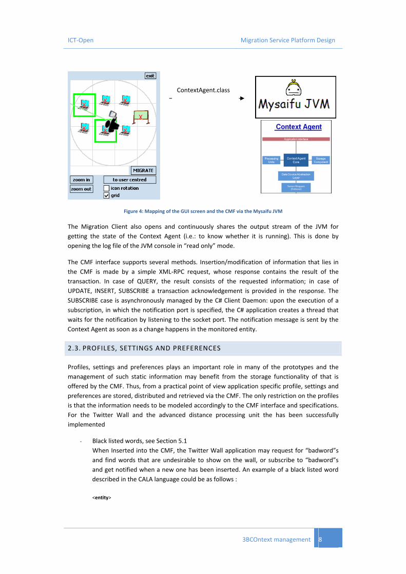
The Context Agent is started when the Migration Client is launched. The JVM instance is created
by the Migration Client by executing the main class of the Context Agent, see Figure 4.
3BCOntext management 7
ICT‐Open Migration Service Platform Design
ContextAgent.class
Figure 4: Mapping of the GUI screen and the CMF via the Mysaifu JVM
The Migration Client also opens and continuously shares the output stream of the JVM for
getting the state of the Context Agent (i.e.: to know whether it is running). This is done by
opening the log file of the JVM console in “read only” mode.
The CMF interface supports several methods. Insertion/modification of information that lies in
the CMF is made by a simple XML‐RPC request, whose response contains the result of the
transaction. In case of QUERY, the result consists of the requested information; in case of
UPDATE, INSERT, SUBSCRIBE a transaction acknowledgement is provided in the response. The
SUBSCRIBE case is asynchronously managed by the C# Client Daemon: upon the execution of a
subscription, in which the notification port is specified, the C# application creates a thread that
waits for the notification by listening to the socket port. The notification message is sent by the
Context Agent as soon as a change happens in the monitored entity.
2.3. PROFILES, SETTINGS AND PREFERENCES
Profiles, settings and preferences plays an important role in many of the prototypes and the
management of such static information may benefit from the storage functionality of that is
offered by the CMF. Thus, from a practical point of view application specific profile, settings and
preferences are stored, distributed and retrieved via the CMF. The only restriction on the profiles
is that the information needs to be modeled accordingly to the CMF interface and specifications.
For the Twitter Wall and the advanced distance processing unit the has been successfully
implemented
‐ Black listed words, see Section 5.1
When Inserted into the CMF, the Twitter Wall application may request for “badword”s
and find words that are undesirable to show on the wall, or subscribe to “badword”s
and get notified when a new one has been inserted. An example of a black listed word
described in the CALA language could be as follows :
<entity>
3BCOntext management 8

ICT‐Open Migration Service Platform Design
<hasIdentifier>Some_#*?%¤!!_word</hasIdentifier>
<entityType>badword</entityType>
<attribute>
<name>word</name>
<type>String</type>
<value>
<string>Some_#*?%¤!!_word</string>
</value>
</attribute>
</entity>
‐ Bluetooth Device Profile used for the processing unit as described in Section 2.1.1.
<entity>
<hasIdentifier>MyMobile</hasIdentifier>
<entityType>BTTriggerPreferences</entityType>
<attribute>
<name>deviceName</name>
<type>String</type>
<value><string>My Nokia Phone</string></value>
</attribute>
<attribute>
<name>btMACAddress</name>
<type>String</type>
<value><string>AA:BB:CC:DD:EE:FF</string></value>
</attribute>
<attribute>
<name>Threshold</name>
<type>String</type>
<value><string>‐3</string></value>
</attribute>
<attribute>
<name>generalInfo</name>
<type>String</type>
<value><string>This is my personal mobile phone...</string></value>
</attribute>
</entity>
3BCOntext management 9

ICT‐Open Migration Service Platform Design
3. MIGRATION ORCHESTRATION
The Migration Orchestration module coordinates all of the phases of the migrations performed
by OPEN prototypes, and is used for all of the applications found in the appendix. As stated in the
deliverable 4.2 [2], it has a server side component running on the OPEN Server and an OPEN
Adaptor running on OPEN Clients.
The server component is a java application that uses XML‐RPC to communicate with OPEN Clients
and with other modules of the Migration Service Platform. The Orchestration Server employs the
Apache XML‐RPC implementation and it can be used as an autonomous XML‐RPC server or as a
Java Servlet.
A java implementation of the Orchestration Adaptor has been developed. It is used to manage
OPEN applications and application components in OPEN devices. This adaptor is not always
needed, and it can have a different implementation or, as happens in the Emergency prototype,
it can be embedded in an OPEN application. The Orchestration Adaptor implements an XML‐RPC
server whose URL can be set using a configuration file.
The Orchestration Server interacts with Orchestration Adaptors in two ways:
‐ Sending XML‐RPC requests to clients. The drawback of that solution is that every
Orchestration Adapter has to implement an XML‐RPC server.
‐ Creating a queue of pending requests. When the Orchestration Server needs to execute a
method of an Orchestration Adaptor it adds a request to the queue. Each Adaptor
periodically executes the server method called “getPendingRequest” and, if a request is
available, the method name to be executed together with its parameters is returned. This
mechanism has been used by the “Emergency” prototype.
In Figure 5 it is possible to see the network configuration of the Migration Orchestration module
with three different clients. The OPEN Server needs a network connection with an IP address
accessible from OPEN Clients (i.e. if clients and server are not in the same LAN a public IP address
is required).
4Bmigration orchestration 10

ICT‐Open Migration Service Platform Design
Figure 5: Network configuration of the Migration Orchestration module
The following functionalities are provided to developed prototypes:
‐ Device registration. Every OPEN device is registered by the Orchestration and a univocal ID
is associated to it. When the Orchestration Adaptor is used, it automatically registers the
device, retrieving its main properties from a configuration file.
‐ Application and component registration. OPEN applications and application components
are registered by the Orchestration and univocal IDs are associated to them. For a
complete definition of application and application components please read the
deliverable 4.2 [2].
‐ Device retrieving. A method allows the application to retrieve the list of devices on which
a group of application components could potentially be executed. The devices on which
the application components are currently running are not included in the returned list.
‐ Application and component retrieving. The Orchestration allows the application to
retrieve the list of OPEN applications and components running on a particular device. This
is useful for the selection of the components to be migrated during a partial migration.
‐ Trigger migration. The Orchestration offers a method that allows the triggering of a
migration. When the trigger is received, the module checks that selected components
can be migrated, that they are supported by the target device, and that they are not
involved in an ongoing migration. Two kinds of migration are supported: web migrations
and application migrations. In the first case, the web UI adaptation has been performed.
In both of the cases the application state is maintained.
In Figure 6 it is possible to see a summary of the main functionalities offered to the developed
prototypes by the Migration Orchestration module.
4Bmigration orchestration 11

ICT‐Open Migration Service Platform Design
Figure 6: Migration Orchestration module
4Bmigration orchestration 12
ICT‐Open Migration Service Platform Design
4. DEVICE SELECTION MAP
Discovery of devices and their respective capabilities is a key feature in the migration process,
and is an important step in all prototypes as well. It is important first of all, because it is
necessary to be aware of which devices can be potential migration targets, and secondly because
the awareness of the capabilities of devices can be the determining factor in deciding where to
migrate. The prototype described in this section shows a discovery concept that includes user
context in the sense of the orientation of the user which is actively used to filter out irrelevant
devices, i.e. devices which are not in the line of sight of the user. The prototype is called the
Device Selection Map.
For the end user, the Device Selection Map is mainly a graphical‐interaction component, which is
embedded in the Open Client Daemon, and which may facilitate her in discovering the available
target devices, their capabilities and their state.
From an internal point of view, the Device Selection Map is also a context‐provider. It is aware of
the layout of the environment and of current location/direction of the user and it raises relevant
events related to the user’s location and/or heading: a “location changed” occurs whenever the
user approaches a new tagged point; a “new device(s) pointed (at)” event is raised only if the set
of the available devices currently in the line of sight of the user changes (i.e. when the user turns
toward a new device).
So far, a DiscoveryMap version for Windows Mobile devices has been developed in C#. The
component expects the following inputs:
‐ XML specification of the environment o Size of the area, expressed in centimeters, and absolute direction of the area,
expressed in degrees (e.g., the heading of the room’s edge with respect to the North).
o Device information for all devices in the area (name, type, address, position within the area)
‐ ID of the tag currently detected by the localization support (we have used so far a RFID infrastructure)
‐ Absolute direction of the user detected by a wearable electronic compass ‐ State of the stationary devices, currently obtained by a device discovery protocol
The component provides the user with a basic map of the environment with respect to the
deployed target devices. Each device is represented by an interactive icon which shows:
‐ the device type: different icons are used for different types ‐ the state of the device: a sign on the top‐left corner of the icon indicates whether the
device is active (V) or not (X).
The current area map is automatically scaled to allow all the devices to fit on the component
widget. However, the user can zoom in or out from the current position in order to have a better
view of the neighboring devices. For facilitating spatial continuity when zooming, a grid of the
area is also displayed.
5BDevice selection map 13

ICT‐Open Migration Service Platform Design
The user’s line of sight is displayed by a green line and the devices s/he is currently pointing are
highlighted by green squares (see Figure 7).
Two main representation modalities are available on the DiscoveryMap:
‐ Map‐centered (or north up): the map is fixed while user icon moves and rotates according to user’s position and direction (see Figure 7.a and Figure 7.b);
‐ User‐centered (or heads up): user icon is on the center of the widget while the map is translated and rotated when the user moves or changes directions (see Figure 7.c and Figure 7.d).
ca
db
Figure 7: Map‐centered (a, b) and user‐centered (c, d) modes.
Two user tests have been performed to evaluate the usability of the Device Selection Map.
From the latest test, which involved 14 people, a preference for the map‐centered mode
emerged. However, both modes are still available on the component (allowing the user to switch
to the preferred one).
The description of the target devices includes the Device Orientation too. Such a value represents
the direction of the target device with respect to the position of the user. It is fundamental to
detect when the user is actually in front of the main side of a device (e.g., at the display of a
desktop PC or of a large screen).
The Device Orientation has been also considered in the user test, where most of the users judged
it as useful.
5BDevice selection map 14

ICT‐Open Migration Service Platform Design
The Device Selection Map integrates with the Migration Orchestration and with the Context
Management Framework (CMF) via XML‐RPC, according to the interfaces defined in [2]. A
function to update the current user orientation in the CMF is already implemented.
Since the Device Selection Map is able to subscribe to updates occurring in the CMF, it could
exploit information that lies in the CMF. For example, the list of discovered devices (that, so far,
comes from an embedded device discovery protocol) and other location related information
(such as discovered Bluetooth beacons) coming from other modules, could be reused in the
Device Selection Map as well.
Temporal features of the devices may be considered. For example, information related to the
estimated amount of time the user has to wait before accessing a busy target device. Time‐
related information should then be available on the CMF.
The Device Selection Map component may in the future be implemented in Java, in order to
make it potentially suitable to any device.
5BDevice selection map 15

ICT‐Open Migration Service Platform Design
5. TRIGGER MANAGEMENT
Trigger Management is the key component for identifying when to trigger a migration as well as
to evaluate and propose a valid trigger scenario for the Migration Orchestrator to execute. Work
Package 3 has been working with two prototypes with different purposes in mind, namely
‐ The Twitter Wall application: To show the evaluation of various valid configurations of
application provided by the Application Logic Reconfiguration module
‐ The Social Game: To show and evaluate the performance of an automatic triggering
mechanism for an IP based video stream
In the following we elaborate.
5.1. TWITTER WALL
A prototype of the Trigger Management module has been developed for the integrated
prototype called “Twitter Wall” see Appendix A for a short description and Deliverable D5.3, [3]
for an elaborated description of the Twitter Wall application. An overview of the “Twitter Wall”
prototype is illustrated in Figure 8.
Figure 8 ‐ Overview of Twitter Wall prototype setup where the application output is migrated between mobile devices
and large screen public display
The “Twitter Wall” prototype demonstrates how an application can be split up in different
functionality executed on different devices e.g. the output can be either on the mobile device or
the public displays. The migration is triggered based on user input, distance to the public displays
and whether blacklisted words are typed into the application making it unsuitable for the public
displays.
The functionality reflected in the prototype Trigger Management prototype includes:
6Btrigger management 16

ICT‐Open Migration Service Platform Design
Ability to take application requirements/preferences and user preferences into account.
A design allowing the addition of other evaluation parameters without a complete
redesign.
Periodic evaluation of requirements, preferences and changes.
Use of different application configurations by Trigger Management.
Both automatic and manual (using RFID tags) triggers.
The trigger management prototype is implemented as a periodic loop which evaluates a set of
application configurations with a set of score functions represented by individual Java methods.
Each score method represents either a requirement or a preference which should be taken into
account in the decision making e.g. whether the user prefers automatic migration or not. Each
method applies a score to each possible application configuration, after which the application
configuration with the highest score can be chosen. If the chosen configuration changes, a trigger
with the new configuration is sent to the orchestrator. If other metrics should be taken into
account they would just become another evaluation method. Three different score levels are
evaluated in the prototype.
1. The TwitterWall application defines a blacklist of words which cannot be displayed on
public displays. This is an application specific requirement. The prototype applies a
negative score of 100 if a blacklisted keyword is entered since this has the highest
decision priority.
2. The TwitterWall defines user settings that specify whether a user is interested in
automatically migrating or not. If a user prefers automatic migration a score of 10 is
added to configurations with devices other than the current device. If the user does not
prefer auto‐migration, a score of 20 is added to configurations with the current device
(see below).
3. The application preferences specify which configuration is the best seen from the
application developer’s point of view. In the TwitterWall application, output on a large
display is considered better than on a small one. The possible configurations are
appointed a score from 0 to 9, with the highest score given to the best configuration
seen from an application point of view.
5.2. VIDEO STREAM
For performance evaluation in Work Package 6, see Deliverable 6.5, [4], a revised prototype
based on the one described in Deliverable 3.2, [5], was modified to use matured components,
where the goal is to trigger a re‐direction of a video stream based on the distance of the user to a
large screen. An overview of the prototype is shown in Figure 9. The Social Game is utilizing such
a video stream; see Appendix B for a short description and [3] for elaborated details.
6Btrigger management 17

ICT‐Open Migration Service Platform Design
LAN 2
Change of location Video server
User
Switch
Access point
Access point
Switch
Switch
LAN 1
Video display migrated
Figure 9: Setup of migrating video stream scenario used for performance evaluation in Work Package 6.
The prototype illustrates the case where the video stream is changed to another device, when
the user is near a suitable screen. Migration is triggered by a change in the distance between the
user’s handheld device and the large screen. A detailed instruction plan for using this prototype
is provided in Appendix D.
5.3. OUTCOME AND SUB CONCLUSIONS
The trigger management prototypes have revealed different aspects which need to be addressed
in a more general trigger management module for the OPEN platform.
The score values used in the prototype are not dynamic enough to be used for all
purposes e.g. there cannot be more than 10 possible configurations to choose from.
Application configurations are not separated for individual users since the Twitter Wall is
a multi‐user application, meaning both users can “vote”/score for the same
configurations. This complicates the scoring algorithm since one user can vote to stay
on a certain device, while another user can vote to migrate which means a way of
prioritizing between these choices is needed.
Further performance results are provided in Deliverable 6.5, [4].
6Btrigger management 18

ICT‐Open Migration Service Platform Design
6. MOBILITY SUPPORT
In this chapter, the prototype to demonstrate the mobility support functionalities within the
OPEN Framework is introduced. As discussed in the Mobility Support section of Deliverable 3.4,
[1], the aim of this prototype is to show how session mobility will be handled in OPEN. There is
no need to show how terminal mobility is handled since it can be supported by implementing the
Mobile IP protocol, which is transparent to both the application and the OPEN service.
OPEN control interface
TargetDevice
OPEN-aware Mobility Anchor Point (MAP)
Application Server
OPEN Migration Server
SourceDevice
Figure 10: The prototype scenario
Figure 10 illustrates the prototype scenario: The Application Server (AS) is providing audio
streaming to the client, which could be either on‐demand music or a VoIP call. The AS is assumed
to be non‐OPEN aware, and it does not support resuming: If the connection is dropped, the user
will have to listen to the music from the beginning, or make a new phone call. Thus, the challenge
of the prototype scenario is to maintain the network connection between the devices and the AS
during and after the migration process.
In addition to the OPEN Migration Server (MS), a new entity called the Mobility Anchor Point
(MAP) is introduced between the devices and the AS. The MAP is an OPEN‐aware SOCKSv5
proxy, which is modified to allow for session mobility. The user's device connects to MAP using
the standard SOCKS protocol, while the OPEN MS controls the MAP via the XML‐PRC interface.
At the source and target devices, the OPEN Middleware provides to the application a socket API
with a SOCKSv5 extension. The application should use this API instead of the operating system's
standard socket API, so that it can utilize the session mobility support. The OPEN middleware is
7Bmobility support 19
ICT‐Open Migration Service Platform Design
then responsible for sending authentication and SOCKS requests to the MAP to establish the
required network connection.
TargetDevice
OPEN-aware SOCKS Proxy
Application ServerOPEN Migration Server
SourceDevice
Source Device’s Registration
IP | TCP | SOCKS CONNECT[SD.addr, SD.port] [SP.addr, 1080]
IP | TCP SYN[SP.addr, SP.port1] [AS.addr, 80]
IP | TCP SYN ACK[SP.addr, SP.port1] [AS.addr, 80]
IP | TCP | SOCKS REPLY OK[SD.addr, SD.port] [SP.addr, 1080]
IP | TCP | HTTP GET[SD.addr, SD.port] [SP.addr, 1080]
IP | TCP | HTTP GET[SP.addr, SP.port1] [AS.addr, 80]
IP | TCP | Audio Streaming[SP.addr, SP.port1] [AS.addr, 80]
IP | TCP | Audio Streaming[SD.addr, SD.port] [SP.addr, 1080]
Target Device’s Registration
Migration Trigger And Application Startup
IP | TCP | SOCKS CONNECT[TD.addr, TD.port] [SP.addr, 1080]
Query OPEN MS
Confirm flow switch
IP | TCP | SOCKS REPLY OK[TD.addr, TD.port] [SP.addr, 1080]
Switching the flow from Source to Target device
IP | TCP | Audio Streaming[SP.addr, SP.port1] [AS.addr, 80]
IP | TCP | Audio Streaming[TD.addr, TD.port] [SP.addr, 1080]
Port 1080 open publicly
Port 80 open publicly
IP | TCP ACK[SP.addr, SP.port1] [AS.addr, 80]
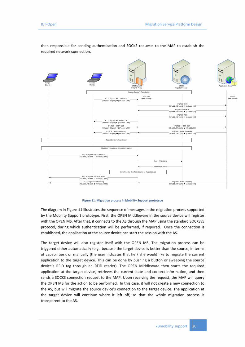
Figure 11: Migration process in Mobility Support prototype
The diagram in Figure 11 illustrates the sequence of messages in the migration process supported
by the Mobility Support prototype. First, the OPEN Middleware in the source device will register
with the OPEN MS. After that, it connects to the AS through the MAP using the standard SOCKSv5
protocol, during which authentication will be performed, if required. Once the connection is
established, the application at the source device can start the session with the AS.
The target device will also register itself with the OPEN MS. The migration process can be
triggered either automatically (e.g., because the target device is better than the source, in terms
of capabilities), or manually (the user indicates that he / she would like to migrate the current
application to the target device. This can be done by pushing a button or sweeping the source
device’s RFID tag through an RFID reader). The OPEN Middleware then starts the required
application at the target device, retrieves the current state and context information, and then
sends a SOCKS connection request to the MAP. Upon receiving the request, the MAP will query
the OPEN MS for the action to be performed. In this case, it will not create a new connection to
the AS, but will migrate the source device’s connection to the target device. The application at
the target device will continue where it left off, so that the whole migration process is
transparent to the AS.
7Bmobility support 20

ICT‐Open Migration Service Platform Design
In conclusion, the introduction of a SOCKS‐based MAP fulfilled the requirement of Session
Management described in D1.2. The ongoing networking, security and application session is
respected when performing migration to provide continuous services.
7Bmobility support 21

ICT‐Open Migration Service Platform Design
7. CONCLUSIONS AND OUTLOOK
The purpose of this document is to introduce what Work Package 3 has been implementing in
terms of prototypes. The document should be read in the context of the architecture documents
such as Deliverable 4.2, [2] and the coming Deliverable 3.4, [1]. As the content of this document
shows, Work Package 3 has, at a prototype level, been focusing on both the supporting
components for the integrated prototypes done in Work Package 4, and on prototypes for
performance evaluation done in Work Package 6. A brief summary of what has been done is as
follows
‐ Context Management Framework
o Context Information access and distribution
Location/distance estimation (RFID and Bluetooth based)
User orientation
o Profile management
‐ Device discovery using user orientation
‐ Migration Orchestration
o Device Discovery
o Device Registering
o Migration orchestration
‐ Trigger Management
‐ Mobility Support
With these prototypes Work Package 3 has demonstrated the platform’s capability to support
the migratory applications and services that have been developed in Work Package 5, and
integrated as a part of Task 4.2 with other components coming from Work Package 2 and Task
4.1. Details on the concepts are found in the coming deliverable 3.4, [1], along with results
related to individual components. There are also a few things which we did not focus on in the
prototyping work, which have been either left for future work (it is important to note that these
are relevant for the project and for service migration, but due to resource limitations they were
not prioritized) or are considered in other ways, e.g. via simulation or emulation. These are
‐ Performance monitoring
‐ QoS configuration
‐ Session Management
‐ Clock/Flow synchronization.
Although, some prototypes have already been evaluated by various tests and performance
measurements in Work Package 6, the next steps with the prototypes described here, will be to
undergo further evaluation in Work Package 6, which evaluates the entire platform.
8Bconclusions and outlook 22

ICT‐Open Migration Service Platform Design
REFERENCES
[1] "Final communication and context management solution for migratory services”, EU FP7
ICT project OPEN, Deliverable D3.4, Due January 2010
[2] “Migration Service Platform Design”, EU FP7 ICT project OPEN, Deliverable D4.2, April
2009
[3] "Final application requirements and design", EU FP7 ICT project OPEN, Deliverable D5.3,
December 2009
[4] "Evaluation Results", EU FP7 ICT project OPEN, Deliverable D6.5, November 2009
[5] “System support for application migration”, EU FP7 ICT project OPEN, Deliverable D3.2,
January 2009
9BReferences 23

ICT‐Open Migration Service Platform Design
GLOSSARY
CALA Context Access LAnguage, an XML formatted specification of a language that
allows a flexible interaction with the Context Management Framework.
Context Agent A software agent running on a device capable of discovering, distributing context
information, whether it has been retrieved or produced locally, and enable access
and subscription to/from applications via an RPC‐XML interface using CALA.
CMF Context Management Framework is the notion of concepts, architecture, and
interface specifications needed to access distributed context information.
Processing Unit A software component that utilizes context information to infer, deduce or in
other way produce new types of context information that can be accessed from a
Context Agent.
Retriever A software component for the Context Agent which interacts with a source
component using a dedicated interface, and converting raw data this into an
understandable format for the Context Agents.
RSSI A signal value indicating the signal strength between two devices.
10BGlossary 24
ICT‐Open Migration Service Platform Design
APPENDIX A ‐ TWITTER WALL APPLICATION
Overall Description
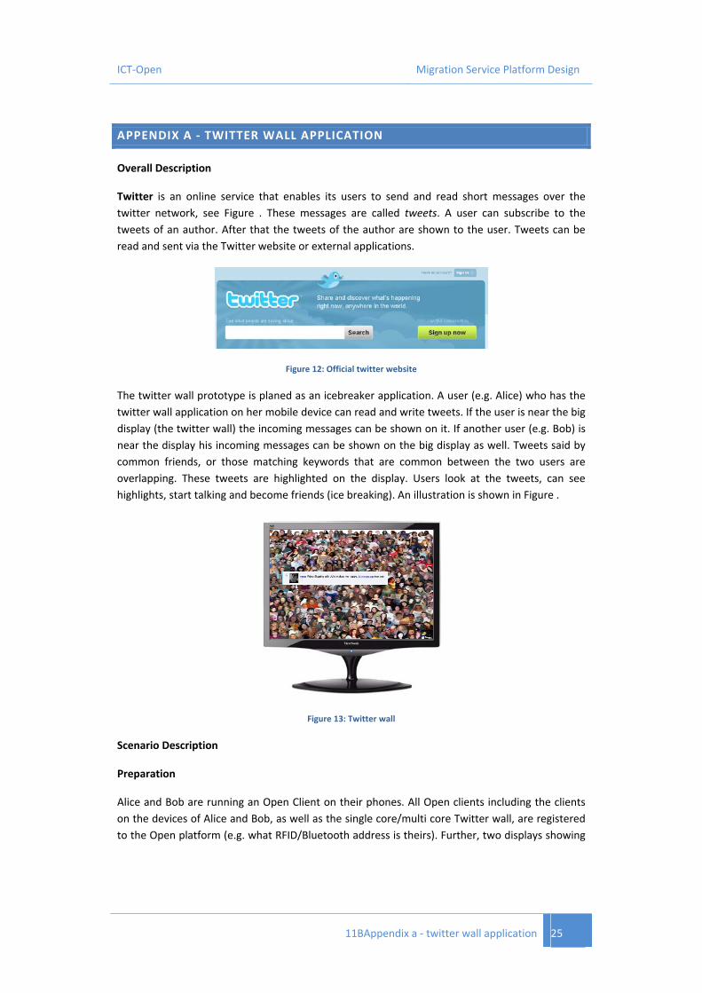
Twitter is an online service that enables its users to send and read short messages over the
twitter network, see Figure . These messages are called tweets. A user can subscribe to the
tweets of an author. After that the tweets of the author are shown to the user. Tweets can be
read and sent via the Twitter website or external applications.
Figure 12: Official twitter website
The twitter wall prototype is planed as an icebreaker application. A user (e.g. Alice) who has the
twitter wall application on her mobile device can read and write tweets. If the user is near the big
display (the twitter wall) the incoming messages can be shown on it. If another user (e.g. Bob) is
near the display his incoming messages can be shown on the big display as well. Tweets said by
common friends, or those matching keywords that are common between the two users are
overlapping. These tweets are highlighted on the display. Users look at the tweets, can see
highlights, start talking and become friends (ice breaking). An illustration is shown in Figure .
Figure 13: Twitter wall
Scenario Description
Preparation
Alice and Bob are running an Open Client on their phones. All Open clients including the clients
on the devices of Alice and Bob, as well as the single core/multi core Twitter wall, are registered
to the Open platform (e.g. what RFID/Bluetooth address is theirs). Further, two displays showing
11BAppendix a ‐ twitter wall application 25

ICT‐Open Migration Service Platform Design
output from a single core and multi core, respectively, are registered. Both users have a profile in
the system including a twitter name.
Scene 1
Alice is using the twitter application on her phone. She's seeing her tweets. Alice walks near a big
display, which are the two displays showing the single core and the multi core outputs. Seeing a
sign on the display, Alice touches her phone with an RFID sticker to the reader by the display.
Alice's tweets are shown on the twitter wall on the display. Alice changes keywords, therefore
showing different tweets on the twitter wall.
Scene 2
Bob enters into the room, cell phone blazing with a certain Bluetooth address. The twitter wall
now also shows Bob's tweets in a blue color. The twitter wall now changes Alice's tweets so they
are shown with a red color. Tweets with the keywords of both of them, or said by common
friends, are overlapping, and are highlighted. Other users can look at the tweets and see who is
most "popular" (most red or most blue). They can see highlights, start talking and become
friends.
The single core display is reconfigured in the platform as being a multi core device, although it is
not. The graphical view now looks fancier, but with a much slower update rate.
Scene 3
Alice types "patent" as one of her keywords, and since this is blacklisted, the Display(s) stop
showing the tweets on the twitter wall. The tweets are now shown on Alice's and Bob's phones.
The shared content is also shown on their phones.
11BAppendix a ‐ twitter wall application 26

ICT‐Open Migration Service Platform Design
APPENDIX B ‐ SOCIAL GAME
This application is a social game that utilizes different types of communicating sub components.
The game is a racing game with extended possibilities to race against real world racing drivers,
make bets and chat with other online people. A screen shot of the game is shown in Figure 14
and details on this game can be found in Deliverable 5.3.
Figure 14: Screen shot of social racing game developed in Work Package 5.
The application is capable of being distributed, meaning that components such as the betting or
chat area can be migrated to other devices, e.g. screens if required. The focus of the prototyping
in Work Package 3, however, has been around the IPTV area, where the platform is used to
efficiently migrate the data stream of the IPTV video from one device to another, while
preserving the actual position of the video.
12BAppendix b ‐ Social game 27

ICT‐Open Migration Service Platform Design
APPENDIX C ‐ EMERGENCY PROTOTYPE
The emergency application focuses on merging simulations of flooding scenarios onto a large
screen for easier comparison. The migration of this application is illustrated by first starting one
simulation and then migrating it to a screen (smart wall). This is followed by starting a second
simulation and migrating it. Currently, only the presentation elements are involved in the
migration. The control elements are merged with those of the first simulation. In this way, the
simulations are synchronized, e.g. same starting and end times, same rate of running animations,
etc. Note that the parameter specifying the initial datasets used for the simulations are not
merged, since the whole point is to compare the results of different input datasets. Details of this
application are described in D5.3, and a screen dump of the application is given in Figure 15.
Figure 15: Screen shot of the emergency prototype application
13Bappendix c ‐ emergency prototype 28

ICT‐Open Migration Service Platform Design
APPENDIX D ‐ SETUP PROCEDURE FOR MIGRATION TRIGGER PROTOTYPE
------- Demo overview and function --------- The demo is showing simple migration functionality of streaming data between two devices, where stream target is determined by user context, namely relative position between a user and a laptop where the stream is outputted to. In the demo, a video stream is used as an example shown by the media player VLC, and relative position is determined by Bluetooth signal strength between the potential laptop and the user who is carrying a Bluetooth enabled device. The system detects automatically the signal strength to any Bluetooth devices nearby, but via preferences on which device to trigger upon and at what threshold a trigger should be instantiated, a somewhat intelligent control of the data stream is achieved. The CMF is picking up the available devices, by frequent scans, and measures the signal strength to any devices, whereas a processing unit inside the CMF is using profile data to sort between discovered devices and matches their signal strength to preference based threshold to trigger migration signals. A separate java code is the orchestrator of the process and does the interaction between the application (the VLC player) and the CMF, which includes interpretation of the CALA XML queries/responses. -------- Basic interaction methods for the CMF ------ There are two useful tools included to interact with the CMF. Both are executed from the CMF/Script/ dir, and are: - executeCalaSubscription.sh which sends a subscription request to the CMF, with specifications indicated in the CMF/conf/CMIConfig.xml. This can be useful to test when the ProcessingUnit makes a trigger. - executeCalaRequest.sh which sends a request to the CMF. This can be useful for reading values from the processing unit and retriever. It is also the needed command to execute Insert, Updates and Delete of profiles needed for the processing unit to make decisions. - From now, I will refer to these scripts as executeCalaSubscription or executeCalaRequest with a specific file to execute. Path of the file are found in either CMF/CALAQueries/BTretrievers or CMF/CALAQueries/DeviceTrigger/. - Notice: all output is given in xml form, and may not necessarily be easy to read by humans. ------- Running the demo ------- 1) Install CMF by copying files to some directory. Configure your installation according to the checklist below. 2) Install OPEN demo by copying files to some directory. Configure your installation according to the checklist below. 3) Start the CMF, by going to CMF/scripts/ with "sudo -E ./startCMN.sh". The "-E" command ensures that you can type the sudo password before any output is made by the CMF, otherwise it is impossible to get it running as it is supposed. Note: the CMF in this configuration needs to be run as sudo (not always the case). 4) Once, CMF is running ensure the profiles are set for your BT-device(s). If you already did this step, you can skip it, although if you in later execution finds that the profiles need to be changed, you can always repeat the Update part of the procedure. You should need to do this only once. First open a console window, and go to CMF_PATH/scripts/ A) First modify the file: Insert_devProfile.xml to include matching information of your device. B) Then execute the following call "./executeCalaQuery.sh Insert_devProfile.xml". This inserts the profile data into the CMF storage C) To adjust the threshold level, which is most likely required you will need to experiment a bit with the threshold levels so it triggers a notification at the right time. To do this, I propose that you will C-1) First check the current levels at different distances, e.g. by executeCalaRequest "OPEN_BT_Query_showsInstantStrength.xml", or "OPEN_BT_Query_showsSimpleStatistics.xml" (which gives you a mean and variance of the measured value) C-2) Edit "Update_devProfile_Threshold.xml" to include a new threshold value based on your observations in 1) C-3) Update it by executeCalaRequest "Update_devProfile_Threshold.xml" with a modified value inside this xml file, and notice if the notifications appears reasonable to that level.
14Bappendix d ‐ setup procedure for migration trigger prototype 29

ICT‐Open Migration Service Platform Design
C-4) Do an executeCalaSubscription "Subscription_puTrigger_showsStatus.xml", and notice when notifications are being send. C-5) Evaluate the notification frequency: If notifications appears to be send either when it is too close or too far away, repeat step C-1 - C-3 again, and evaluate (i.e. step 5). You do not have to repeat step 4 again. 6) Once done, you may executeCalaRequest "Unsubscribe_puTrigger.xml" (but beware you need to ensure the subscription ID number in the "Unsubscribe_puTrigger.xml" is matching the one that is given in each notification you receive. Otherwise you will not stop receiving notifications! Note: If this procedure for some reason fails, and there are no profile present in the storage, nothing will happen subsequently. Note: It is beneficial that the two devices are put somewhat a bit far from each other, so there is reasonable difference in signal strength from the device to detect reliably whether the device is at one or the other laptops. 5) Once you have the preferences ready in the CMF, you should basically be ready to run the demo. Open another console window and go to OPENDEMO/ and execute openMyDemo.sh. Now from here, things should happen automatic, i.e. video stream being shown on one or the other device. 5A) you might want to reconfigure parts of the system to fine tune settings, whereas the possible reconfiguration possibilities are briefly described below in the system configuration section. 6) To stop the demo, for now you will have to "kill" all involved processes. In principle, you can have the CMF running without killing that too, but if you start the demo -> kill it, several times, you will over time get a lot of subscriptions left with no recipients inside the CMF, leading to a lot of exceptions. Note: once you have done this procedure at least once, you need only to do step 3) and 5) to start the demo! --Notice: The demo still have a few bugs and stuff, so sometimes it throws some exceptions, but in most cases it should not cause to alarm. In worst case, try to kill the DemoCode and restart it.... ------ Check list ------- Hardware requirements - 2 laptops with WLAN connection to each other, and bluetooth interface - 1 bluetooth enabled handheld device Software requirements - Java 1.5 or higher is installed and correctly setup (the sun version, and not the gcc version!) - VLC is installed. The demo has succesfully been tested with v0.9.9a Grishenko, while problems with previous versions has been observed - hcitool installed System environment variables to be set: CMF_PATH : to the root location of the CMF installation, e.g. in bash.bashrc add line export CMF_PATH="/usr/local/CMF" OPENDEMO_PATH : to the root location of the OPEN Demo, e.g. add line export OPENDEMO_PATH = "/usr/local/OPENDEMO" CMF configuration - CMF - CMN.xml: IPaddresses, port numbers, paths to DSAM and PS configuration files - PS_BTTrigger.xml: databaseConfig->filePath+Name to the location of where to put the database Demo configuration - OPEN Demo - demoConfigFile.xml: check all cmf* tags that they fit with the local CMN parameters given in previous step - OPENDemo* tags: check IP address, and used port and change if needed - *script tags: check that the scripts are present in the same directory as the open demo - IsDemoServer: check that only on laptop has this flag set to true, and all others has their values on false - demoScripts:
14Bappendix d ‐ setup procedure for migration trigger prototype 30

ICT‐Open Migration Service Platform Design
14Bappendix d ‐ setup procedure for migration trigger prototype 31
- startStreamServer.sh: Check it points to a VALID video clip (BigBuckBunny_320x180.mp4 found on the Internet via google has been tested and works, however some other clips may for some reason not work with given parameters!). Check that IP address and port matches the stream servers setting. Ports needs to be different than the CMF settings! - stopStreamServer.sh: not important for time being, but later it will. Needs to check whether content in the brackets "" match 100% to input line in startStreamServer.sh - startClientVLC.sh: check IP address and port matches the stream servers output port - stopVlcClient.sh: check that the content in the brackets "" matches the input line in startClientVLC.sh script -------- System configuration ------- The retriever that picks up the bluetooth signal may be configured via the DSAM_BTRetriever.xml file, found in CMF/conf/SCMF/ - measurementInterval: timeinterval in ms per Bluetooth signal strength measurement - scanInterval: timeinterval in ms between Bluetooth device discovery - bufferSize: size of buffer from where statistics are created. Notice, the PU is configured to use the statistical information to trigger.... The Processing Unit may be reconfigured as follows - preferenceCheckIntervalTime: the interval time in ms where the PU checks for new profile data. Existing profiles have subscriptions associated, so the PU will be instantaniosly notified whenever updates are made. This is only for new profiles to be detected!