aapm scientific meeting patient dose in ct: imaging … · california sb 1237 requires reporting on...
TRANSCRIPT

1
AAPM Scientific Meeting
Imaging Symposium
Patient Dose in CT: Calculating
Patient Specific Doses in CT
(Joint with Education)
Michael McNitt-Gray, PhD, DABR, FAAPM; UCLA
Peter Caracappa, PhD, CHP; RPI
Ehsan Samei, PhD, DABR, FAAPM, Duke
Patient Dose in CT:
Calculating Patient Specific Doses in CT
1. Limitations of current metrics (e.g. CTDIvol) and methods in
estimating patient dose (McNitt-Gray)
2. Methods to more accurately estimate dose that take into
account scanner, exam and patient factors (McNitt-Gray)
3. The role of Computational Phantoms, Monte Carlo
simulation in developing patient-specific dose estimates
(Caracappa)
4. Estimate patient-specific organ doses, effective doses, and
radiation risk for comparison and optimization purposes
(Samei)
Acknowledgements
• Funded by NIBIB grant R01EB004898
• Recipient of Research Grant Support
from Siemens Medical Solutions
Patient Dose in CT:
Calculating Patient Specific Doses in CT
Questions to keep in mind:– Should we calculate patient specific dose?
– How accurately do we need to calculate this?• Does it vary from purpose to purpose (fetal dose,
meet legal requirements, etc.)
– Do we need to calculate for EACH patient? Or just for a “class” of patients (Large adult male)
• Should we do online realtime Monte Carlo for each patient?
• or precalculate doses somehow?

2
Background• NCRP 160 and (Mettler et al, Health Physics, Nov 2008)
Estimated US averages 1980 2006
Estimated Average Annual
Radiation Dose
(whole body eff. dose in mSv)
3.6 mSv/yr 6.0 mSv/yr
From Medical Radiation 0.54 mSv/yr
15% of total
3.0 mSv/yr
50% of total
From CT --- 1.5 mSv/yr
25% of total
Background• CT procedures
– Estimate 18.3 million in 1993
– Estimate 62.0 million in 2006
– 10% annual growth• Slightly higher since introduction of MDCT (1994-1998)
– Could be over 100 million by now
Current Dose Metrics
Many Organizations suggesting that CT dose be
tracked (NCI, IAEA, ACR, FDA, etc.)
California SB 1237 requires reporting on CT dose
by July 1st, 2012 , one of the following:
“The computed tomography index volume (CTDIvol) and dose
length product (DLP), as defined by the IEC and recognized by
FDA; The dose unit as recommended by the American
Association of Physicists in Medicine”.
Current Dose Metrics
What is available to be recorded now?
CTDIvol and DLP
• What could we do in the future?
• Organ Dose
– Could be tracked across scans and across time
– Accumulated organ dose over time

3
Current Dose Metrics
What is available to be recorded now?
CTDIvol and DLP
• What could we do in the future?
• Organ Dose
– Could be tracked across scans and across time
– Accumulated organ dose over time
CTDIvol and DLP
• CTDIvol reported on the scanner
• Is Dose to one of two phantoms
• Is NOT dose to the patient
• Does not tell you whether scan was done “correctly” or “Alara” without other information (such as body region or patient size)
• MAY be used as an index to patient dose with some additional information
CTDI and Patient Dose :
They Are Not the Same Thing• McCollough et al, Radiology, May 2011 ; 259:311–316
• CTDI DOES REPRESENT:
– A measure of scanner output (with limitations
being addressed by TG 111 and TG 200)
– Well defined and highly reproducible across CTs
• CTDI DOES NOT REPRESENT
– Patient dose – does not take into account patient
size, shape, composition, scan length
– Dose from scans with no table motion (perfusion)
Scenario 1: No adjustment in
technical factors for patient size
32 cm phantom 32 cm phantom
CTDIvol = 20 mGy CTDIvol = 20 mGy
The CTDIvol (dose to phantom) for these two would be the same
100 mAs 100 mAs

4
Scenario 2: Adjustment in technical
factors for patient size
32 cm phantom 32 cm phantom
CTDIvol = 10 mGy CTDIvol = 20 mGy
The CTDIvol (dose to phantom) indicates larger patient received 2X dose
50 mAs 100 mAs
Did Patient Dose Really Increase ?
For same tech. factors, smaller patient absorbs more dose
– Scenario 1: CTDI is same but smaller patient’s dose
is higher
– Scenario 2: CTDI is smaller for smaller patient, but
patient dose is closer to equal for both.
AAPM TG 204
Size Specific Dose Estimates
Based on Both
Simulations and
Measured Data
CTDIvol
• UNDER estimates dose for small patients
(have to multiply by > 1)
• OVER estimates dose for large patients
• (have to multiply by < 1)

5
CTDIvol
• Not patient Dose
• By itself can be misleading
• CTDIvol should be recorded with:
– Description of phantom size (clarify 16 or 32 cm diameter)
– Description of patient size (lat. Width, perimeter, height/weight, BMI)
– Description of anatomic region
Tracking/Reporting Dose?
• What should we record/report?
• What do we tell patient?
• What do we tell referring physician?
• CTDIvol? DLP?
• Total CTDIvol? Total DLP?
• Calculate Effective Dose from Total DLP*k?
Monte Carlo Simulation Methods for
Estimating Radiation Dose
• Monte Carlo methods
– Used in CT for some time
• NRPB report 250 (1990)
• GSF (Zankl)
Background
• These early reports used:
– Detailed Models of Single Detector, Axial Scanners
– Idealized (Nominal) collimation
– Standard Man Phantom
• MIRD V (geometric model)
• Eva, Adam

6
Monte Carlo for CT Dose - Details• Monte Carlo Packages
– MCNP (Los Alamos)
– EGS
• Model Transport of Photons from modified (CT) source
• Probabilistic interactions of photons with Tissues
– Photoelectric, Compton Scatter, Coherent Scatter
• Tissues need detailed descriptions
– Density
– Chemical composition (e.g. from NIST web site)
Background
• These form the basis for:
– CT Dose computer program
– CT Expo
– ImPACT dose calculator
– k factor approach (Effective dose = k* DLP),
which was derived from NRPB simulated data
Current Approaches
• Model Scanner (e.g MDCT) in detail
• Model Patient (Geometric, Voxelized)
• Simulate Scan
• Tally Organ Dose
Modeling the CT scanner• Spectra
– Function of beam energy
• Geometry
– Focal spot to isocenter, fan angle
• Beam Collimation
– Nominal or actual
• Filtration
– Bowtie filter (typically proprietary)
– Other add’l filtration (also proprietary)
• Tube Current Modulation Scheme– x-y only, z-only, x-y-z, etc.
Photon Fluence Spectra
0.000E+00
5.000E+10
1.000E+11
1.500E+11
2.000E+11
2.500E+11
3.000E+11
0 50 100 150 200
Energy in keV
Ph
oto
n F
luen
ce
80 kVp Spectra
125 kVp Spectra
150 kVp
Normalized Dose
0.000
0.250
0.500
0.750
1.000
1.250
40 60 80 100 120
Distance (mm)
No
rmali
zed
Do
se
128 mm in air at iso
0.000
0.100
0.200
0.300
0.400
0.500
0.600
0.700
0.800
0.900
1.000
1.100
0 10 20 30 40 50 60 70 80 90 100 110 120 130 140 150 160
distance in mm
rela
tive d
ose
128 mm in air at iso

7
Modeling the CT scanner
• Source Path - dependent on scan parameters:
• Nominal collimation
• Pitch
• Start and Stop Locations (of the source)
0
100
200
300
400
500
600
0 50 100 150 200 250 300
Table Position (mm)
Tu
be
Cu
rre
nt
(mA
)
90 degrees
(AP)
Shoulder
Region
Lung
Region Abdomen
180 degrees
(LAT)
Breast
Tissue
Long Axis Modulation
Validating the CT Scanner Model
• Benchmark MC Model against physical
measurements
– CTDI Phantoms
• Head and Body
• Simulate a tally in a pencil chamber
• Each kVp and beam collimation combination
• Measured vs. Simulated
– Aim for < 5% difference between Simulated
and Measured
Modeling the Patient• Geometric
– e.g MIRD
– Standard man
– Often androgynous (male/female organs)
– Usually single size
• Size and age variations
– newborn, ages 1, 5, 10, and 15 years
– adult female, and adult male
– Including pregnant patient

8
Modeling the Patient
• All radiosensitive organs identified
– Location
– Size
– Composition and density
Modeling the Patient
• Voxelized Models
– Based on actual patient scans
– Identify radiosensitive organs –
usually manually
– Non-geometric
• Different age and gender
• Different sizes
Modeling the Patient• GSF models (Petoussi-Henss N, Zankl M et al,
2002)
– Baby, Child, three adult females (shown), two adult
males, Visible Human
– All radiosensitive organs identified manually (ugh!)
Modeling (Parts of) the Patient
• Embryo/Fetus
• Breast

9
Uterus
Gest. Sac
Uterus
Gest. Sac
7 weeks (embryo not visible)Mature Fetus:
36 weeks
Contoured Image Voxelized Model
Ea
rly
Ge
sta
tio
nL
ate
Ge
sta
tio
n
Original Image
Original Image
Threshold Image
Contoured Image
Voxelized Model

10
Simulating the Scan• Select Technical Parameters
– Type of scan (helical, axial)
– Beam energy
– Collimation
– Pitch
– Tube Current/rotation time (or tube current modulation)
• Select Anatomic Region
– Head/Chest/Abdomen/Pelvis/etc.
• Translate this to:
– Start/stop location -> Source Path
Monte Carlo Methods and Patient Size
Fetal Dose as a Function of Patient Perimeter
y = -0.12x + 23.11
R2 = 0.68
0
2
4
6
8
10
12
14
16
85 90 95 100 105 110 115 120 125
Perimeter of Mother (cm)
No
rmalized
Feta
l D
ose (
mG
y/1
00m
As)
Angel et al Radiology 2008
Angel et al, PMB Feb 2009
Tube current versus x-axis location of the TCM schema for a
patient model with a perimeter of 125cm. Background is a
sagittal view of the patient.
11
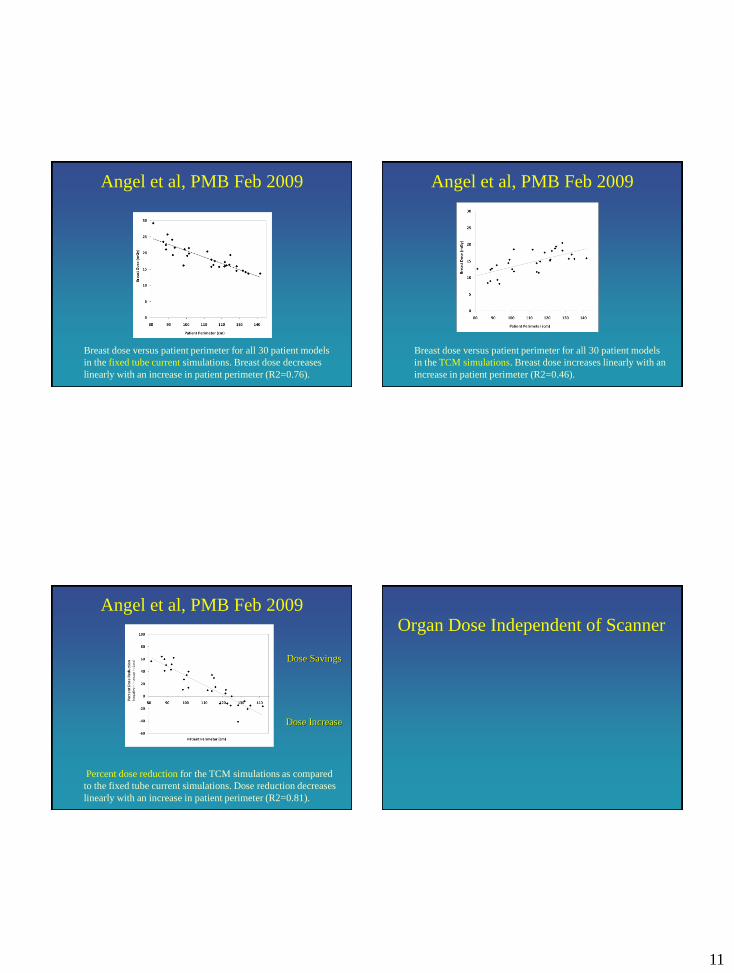
Angel et al, PMB Feb 2009
Breast dose versus patient perimeter for all 30 patient models
in the fixed tube current simulations. Breast dose decreases
linearly with an increase in patient perimeter (R2=0.76).
Angel et al, PMB Feb 2009
Breast dose versus patient perimeter for all 30 patient models
in the TCM simulations. Breast dose increases linearly with an
increase in patient perimeter (R2=0.46).
Angel et al, PMB Feb 2009
Percent dose reduction for the TCM simulations as compared
to the fixed tube current simulations. Dose reduction decreases
linearly with an increase in patient perimeter (R2=0.81).
Dose Increase
Dose Savings
Organ Dose Independent of Scanner

12
Organ dose (in mGy/mAs) and effective dose (in
mSv/mAs) for GSF model Irene resulting from a whole
body scan with similar parameters for each scanner
Turner et al Med Phys 2010
Organ dose and effective dose normalized by measured
CTDIvol for GSF model Irene resulting from a whole
body scan.
Turner et al Med Phys 2010
Normalized Organ Dose as function of Pt. Size
(Abdomen Scans for each Patient)
y = 3.780e-0.011x
R² = 0.970
0.0
0.5
1.0
1.5
2.0
2.5
3.0
25 50 75 100 125 150
Mea
n o
rgan
do
se/C
TD
I volac
ross
sca
nner
s
Patient Perimeter (cm)
Stomach
Liver
Adrenals
Gall Bladder
Kidney
Pancreas
Spleen
Expon. (Stomach)
Baby
Irene
Child
GolemDonna
Visible
Human
Helga
Frank
Turner et al Med Phys 2011
Future of Dosimetry?
Patient
Size info
CTDIvol
(or TG 111)
Size
Coefficients
Patient Organ Dose
•Accounting for patient size
•Accounting for scanner
•Accounting for anatomic region

13
Radiation Dose : Organ Dose
• BEIR VII report (2005)
– Risk based on radiation dose to organ, age,
gender, etc.
• ICRP 103 (2007)
– Calculates “effective dose” based on weighted
sum of organ dose
• Use dose to radiosensitive organs as a basis
for estimating metrics that relate to risk
Summary - Estimating Organ Doses
• Organ Doses are meaningful indicators of Dose
• More informative than CTDI, DLP, E alone
– Take into account differences in scanner
– Take into account differences in patient size
– Take into account differences in body region
– Take into account dose reduction methods (TCM)
• Will be a better indicator as to when we truly reach sub mSv exam
Summary - Estimating Organ Doses
• Demonstrate feasibility of NOT having to do detailed analysis on each Patient
• Not quite ready for implementation
• A path to estimate organ doses that takes into account:
– Scanner
– Acquisition parameters (including TCM)
– Anatomic Region
– Patient Size
Acknowledgements
• Funded by NIBIB grant R01EB004898
• Technical Support from:
– Siemens Medical Solutions
– GE Healthcare
– Toshiba Medical Systems
– Philips Healthcare