abc oil and gas - ogee lite injection - sample.pdf · abc oil and gas . august 15th, 2016 . report...
TRANSCRIPT


ABC Oil and Gas
August 15th, 2016
Report No: SMP-0003 ABC 08-16 Wellsite Chemical Injection Addition
Powered by Solaris-MCI
Report No: SMP-0003
Powered by Solaris-MCI Page 2
Contents Executive Summary 3
1.0 Assumptions 3
Napkin Assumptions 3 1.1.
Client Discussed Assumptions 4 1.2.
Ogee Assumptions 4 1.3.
2.0 Scope of Assessment 4
3.0 Results 5
Assessment 5 3.1.
Configuration 6 3.2.
Estimate 7 3.3.
Estimate Basis 7 3.4.
Future Considerations 8 3.5.
Additional Requirements 8 3.6.
Appendix A: Client Supplied Ogee Napkin 10
Appendix B: Ogee Marked-up Drawing 13

Report No: SMP-0003
Powered by Solaris-MCI Page 3
Executive Summary
The two wells located at the ABC 08-16 wellsite have been experiencing operational issues due to wax build-up downhole. The build-up of wax in the wellbore can result in partial or complete loss of production for a well.
The installation of a new chemical injection system will help remove existing wax build-up and can help prevent future build-ups.
The chemical injection system consists of two pneumatic injection pumps, one double walled plastic chemical storage tank and associated stainless steel tubing, valves and fittings.
Ogee has provided a Total Installed Cost estimate of $72,500 (-20%/+40%) for a proposed configuration based on the process conditions and drawings submitted for the ABC 08-16 Wellsite. Ogee has also identified future considerations, including engineering requirements, to progress this scope to the next phase.
1.0 Assumptions
1.1 Napkin Assumptions
As per your information submitted through the Ogee napkin on August 10th, 2016:
Assessment Type: Wellsite Location: ABC 08-16 Wellsite Commodity: Natural Gas Sweet/Sour: Sour Conditions: Two wells at 08-16 have been experiencing issues with
wax build up. The wax issues have required the wells to be shut-in, which has resulted in a loss of production. A chemical injection system is required to deal with the production issues with these wells.

Report No: SMP-0003
Powered by Solaris-MCI Page 4
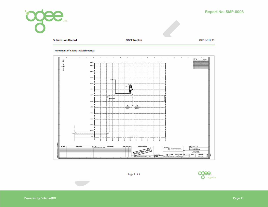
A copy of the submitted Ogee Napkin is included in Appendix A.
1.2 Client Discussed Assumptions
As per the Ogee kick-off call on August 19th, 2016, the following are the assumptions discussed with the client:
• Operating pressure: 2,100 kPag,
• Operating temperature: 25oC,
• Wellhead shut-in pressure: 25,000 kPag,
• Wellhead flow rate: 25 e3m3/d,
• Up to 40 liters per day of chemical injection needed,
• Fuel gas source is available for pump.
1.3 Ogee Assumptions
The following are assumptions Ogee has made to complete this report:
• Plot space is available for the addition tank,
• Space is available in the existing heater/meter building,
• Piling is not required for the tubing,
• An injection point is available at the wellhead.
2.0 Scope of Assessment
Ogee has reviewed the option of adding chemical pumps to the existing line heater/meter building. The chemical injection pumps will pump wax dispersant at a high pressure into the wellhead and will aid with the removal and prevention of wax build-up. In addition to the chemical pumps, the chemical injection system will also need stainless steel tubing, fittings and valves, as well as a level gauge and chemical storage tank with piles.
Report No: SMP-0003
Powered by Solaris-MCI Page 5
This option was chosen due to the following:
• Low cost option when comparted to well servicing operations,
• Operations able to adjust pump rates as required to minimize chemical consumption,
• Ability to service pump/tanks while the wellsite is operational for short duration without chemical injection capabilities.
3.0 Results
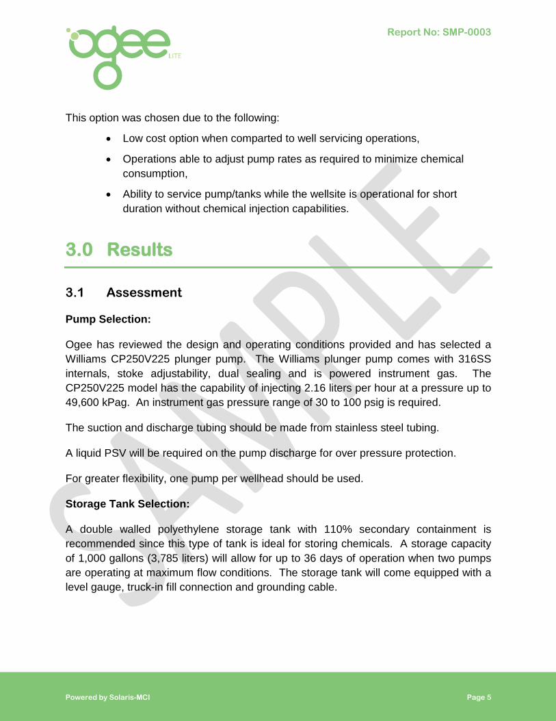
3.1 Assessment
Pump Selection:
Ogee has reviewed the design and operating conditions provided and has selected a Williams CP250V225 plunger pump. The Williams plunger pump comes with 316SS internals, stoke adjustability, dual sealing and is powered instrument gas. The CP250V225 model has the capability of injecting 2.16 liters per hour at a pressure up to 49,600 kPag. An instrument gas pressure range of 30 to 100 psig is required.
The suction and discharge tubing should be made from stainless steel tubing.
A liquid PSV will be required on the pump discharge for over pressure protection.
For greater flexibility, one pump per wellhead should be used.
Storage Tank Selection:
A double walled polyethylene storage tank with 110% secondary containment is recommended since this type of tank is ideal for storing chemicals. A storage capacity of 1,000 gallons (3,785 liters) will allow for up to 36 days of operation when two pumps are operating at maximum flow conditions. The storage tank will come equipped with a level gauge, truck-in fill connection and grounding cable.

Report No: SMP-0003
Powered by Solaris-MCI Page 6
Tie-Ins:
The chemical injection system will require the following tie-ins:
• Instrument gas,
• Produced gas (at wellheads).
3.2 Configuration
The two pumps for the chemical injection system should be installed in the existing line heater/meter skid. If there is not enough room in the skid, a small enclosure can be used to house the pumps, but this has not been taken into consideration with the estimate provided.
Instrument gas will be required to power the pumps. Tubing will need to be routed to the power end of the pump from the instrument gas tie-in.
Tubing will need to be routed from the tank outlet to the suction side of the pump. Refer to vendor requirements for the elevation difference between the tank outlet and suction inlet.
Tubing from the pump discharge to the injection point at the wellhead should be routed with the existing piping or cable tray to/from the wellhead.
Vent tubing shall be routed from the pump to a location that will allow for safe venting. It is recommended that vent tubing is extended above the building eave, in accordance with area classification per the Canadian Electrical Code. A muffler can be installed on the tubing vent to reduce the noise associated with venting.
The chemical tank should be installed next to the existing tank for trucking access for fill-ups.
See Appendix B for Ogee marked-up drawings of a proposed configuration on the client-supplied PFD.

Report No: SMP-0003
Powered by Solaris-MCI Page 7
3.3 Estimate
The estimate for the configuration is provided in Table 1 below.
Table 1: Estimate of Recommendation
3.4 Estimate Basis
The Total Equipment Cost Estimate (Line Item 5 of Table 1) is based on the purchase of equipment by Solaris-MCI for projects of similar scope. The Total Construction Labour Cost Estimate (Line Item 6 of Table 1) is based on the experience of Solaris-MCI with this type of installation and includes estimates for piling, earthworks, installation materials, programming/commissioning, engineering and professional services.
ITEM QUANTITY UNIT TOTAL COST
Equipment
1 Chemical Pump 2 Each $8,000
2 Storage Tank w/ Top fill, Hose, Sight glass 1 Each $4,500
3 Stainless Steel Tubing 75 $/m $700
4 Piles and Structural Steel 1 Lot $7,000
5 Total Equipment $20,700
6 Construction Labour Costs $25,300
7 Total Indirect Costs $15,000
Subtotal $61,000
7 Transportation Allowance 1 Lot $600
8 Contingency 15 % $10,900
TOTAL INSTALLED COST (TIC) $72,500
ESTIMATE RANGE (-20% to +40%) $58,000 to $101,500

Report No: SMP-0003
Powered by Solaris-MCI Page 8
3.5 Future Considerations
The following items will need to be addressed in future phases:
Process Requirements:
During the detailed design phase, the following will need to be addressed and designed:
• Instrument gas take-off,
• Suction pressure requirements based vendor data,
• Suction and discharge tubing sizing.
Mechanical Requirements:
During the detailed design phase, the following will need to be addressed and designed:
• Tubing routing,
• Tubing material and wall thickness selection.
Civil / Structural Requirements:
During the detailed design phase, the following will need to be addressed and designed:
• Piling and support design.
Regulatory Requirements:
• As required by governing bodies.
3.6 Additional Requirements
In the event that you require this project to be carried to the detailed engineering phase, Ogee will connect you with Solaris-MCI, our fully-integrated, multi-discipline engineering firm, to discuss options.

Report No: SMP-0003
Powered by Solaris-MCI Page 9
Note: This document is not an engineering or design document. This document is provided for general information purposes only and does not replace the requirements and details in the acts, regulations, standards and other applicable documentation, including any amendments, updates, revisions, etc. The user is still responsible for ensuring that the facility or pipeline complies with all requirements, irrespective of the information provided in this document.

Report No: SMP-0003
Powered by Solaris-MCI Page 10
Appendix A: Client Supplied Ogee Napkin
Report No: SMP-0003
Powered by Solaris-MCI Page 11

Report No: SMP-0003
Powered by Solaris-MCI Page 12

Powered by Solaris-MCI Page 13
Appendix B: Ogee Marked-up Drawing
Not For Construction