abletonlive manual
TRANSCRIPT

1

Live Version 5.0 for Windows and Mac OS
Created by Bernd Roggendorf, Gerhard Behles, Robert Henke, awi, Reiner Rudolph, StefanHaller, Torsten Slama, Eduard Mueller, Stefan Franke, Frank Hoffmann, Andreas Zapf, Hans-Thomas Mueller, Henrik Hahn, Ralf Suckow, Gregor Klinke, Matthias Mayrock, FriedemannSchautz, Ingo Koehne.
Reference Manual by Rose Knudsen, Gerhard Behles, Jakob Rang, Robert Henke, TorstenSlama.Loops and samples provided by Big Fish Audio.Web: www.big�shaudio.comE-mail: info@big�shaudio.comAddress: 11003 Penrose Street, Suite C, Los Angeles, CA 91352
Copyright 2005 Ableton AG. All rights reserved.
This manual, as well as the software described in it, is furnished under license and may be used or copied only in accordance withthe terms of such license. The content of this manual is furnished for informational use only, is subject to change without notice andshould not be construed as a commitment by Ableton. Ableton assumes no responsibility or liability for any errors or inaccuraciesthat may appear in this book.
Except as permitted by such license, no part of this publication may be reproduced, stored in a retrieval system or transmitted, inany form or by any means, electronic, mechanical, recording or otherwise, without the prior written permission of Ableton.
Macintosh, Audio Units and QuickTime are registered trademarks of Apple Computer, Inc. Windows is a registered trademarkof Microsoft Corporation. VST is a trademark of Steinberg Media Technologies GmbH. ReWire is a trademark of PropellerheadSoftware AB. Mackie Control is a trademark of LOUD Technologies Inc. Ogg Vorbis and FLAC are trademarks of Xiph.Org. Abletonis a trademark of Ableton AG. All other product and company names are trademarks or registered trademarks of their respectiveholders.

Chapter 1
Welcome to Live
1.1 The Ableton Team Says: Thank You
Live is the result of musicians wanting a better way to create, produce and perform musicusing a computer. A great deal of effort has been put into making Live easy and fun touse, yet at the same time capable of helping you create music with unlimited depth andsophistication. This effort continues even as you read these lines... in fact, a new, improvedLive version might already be available for download! Please check on our website now1,or choose �Check for Updates� from the Help menu.
We hope you enjoy using Live and that it enhances your creative process. Should you havesuggestions about how we can improve Live, please let us know2.
1http://www.ableton.com/[email protected]
1

1.2. WHAT'S NEW IN LIVE 5? 2
Your Ableton Team.
1.2 What's New in Live 5?
1.2.1 Remix Features
� Support for MP3, Ogg Vorbis, Ogg FLAC and FLAC compressed audio �les (seeSample Files)
� Auto-Warp (see Syncing Longer Pieces)
� Complex Warp Mode (see Complex Mode) for warping music containing beats, tonesand textures
� Clip scrub, nudge and improved transport controls (see Clip Offset and Nudging)
1.2.2 Organizational Tools for Files and Sets
� File search function (see Searching for Files)
� Better browsing for �les and folders (see Working with the File Browsers)
� Live Clip (see Live Clips) format for easy storage and retrieval of clip and device settings
� Import and export of Live Sets (see Importing and Exporting Sets with the Browser)and their components directly from the Browser
� Open Recent Set command

1.2. WHAT'S NEW IN LIVE 5? 3
1.2.3 Clip and Track Enhancements
� Track Freeze (see Track Freeze) for conserving CPU resources and simplifying projectsharing
� Track Delay controls (see Track Delays) to control for human, acoustic and hardwaredelays
� Multi-selection clip editing (see Clip View)
� Clip deactivation option (see Clip Activator Switch)
1.2.4 Working with Arrangements
� Launchable Arrangement Locators (see Launching the Arrangement with Locators)
� New Arrangement Transport (see Transport)
� Track I/O in the Arrangement View (see Routing and I/O)
1.2.5 Editing MIDI
� Detailed and adaptive MIDI quantization options (see Arranging and Quantizing Notes)
� Preview in the MIDI Editor (see The MIDI Editor)
� MIDI note deactivation option (see Deactivating Notes)
1.2.6 MIDI and Key Remote Control
� Mackie Control support (see Mackie Control)

1.2. WHAT'S NEW IN LIVE 5? 4
� Improved mapping for the crossfader (see Using Live's Crossfader)
1.2.7 Resources
� Valuable library (see The Library) of clips, device presets and Live Sets
� Library expansion and customization with Live Packs (see Live Packs)
� New interactive built-in program lessons (see Learn About Live)
1.2.8 Live Effects and Instruments
� Beat Repeat (see Beat Repeat) for reorganizing and �shredding� beats and vocals
� Phaser (see Phaser) and Flanger (see Flanger)
� Auto Pan (see Auto Pan) for LFO-driven manipulation of amplitude and panning
� Saturator (see Saturator) for subtle-to-drastic distortion effects
� Arpeggiator (see Arpeggiator)
� New features for Simpler (see Simpler) and Operator (see Operator)
1.2.9 Using Devices
� Browser-based device preset management (see Live Device Presets)
� Device groups (see Device Groups) for saving multi-effect combinations together withinstruments
1.2. WHAT'S NEW IN LIVE 5? 5
� Device delay compensation (see Device Delay Compensation) for Live and plug-ininstruments and effects
� Live can receive MIDI messages from plug-ins
� VST Plug-ins can be stored in various directories (see The VST Plug-In Folder)
1.2.10 Miscellaneous
� (PC) / Ctrl (Mac) context menus for many commands and settings
� Zoom-adaptive or �xed grid options (see Using the Editing Grid)
� Count-in recording (see Recording with Count-in)
� Monitoring status easily visible when the In/Out section is hidden
� Files, Sets and presets can be dragged into Live from the Explorer (Windows) / Finder(Mac)

Chapter 2
First Steps
When you install Live and run it for the �rst time, you will be presented with the ProductsPreferences tab.
If you own Live, you can authorize your copy of the software by selecting it from the listedproducts and clicking the Unlock button at the bottom of the window. Please see thechapter on unlocking Live (see Unlocking Live) should you have questions or concerns thatarise during the unlocking process.
If you do not (yet) own Live, you can close the Preferences and proceed, as Live will run inDemo Mode by default. In Demo Mode, you will be able to work with all of Live's featureswith the exception of saving and exporting.
6
2.1. LEARN ABOUT LIVE 7
2.1 Learn About Live
Live comes with a set of interactive lessons to take you step by step through the key featuresof the program. The lessons are organized in a table of contents, which can be openeddirectly in the program via the Help menu. We highly recommend following the lessons.Many users have told us that the lessons helped them get familiar with the program veryquickly.
We also recommend that you read the Live Basics chapter (see Live Basics), which encap-sulates everything that Live is and can do, and is therefore a worthwhile read for bothbeginners and experienced users. The remaining chapters of this manual serve as in-depthreference for the material introduced in Live Basics.
2.1.1 Using the Info View and Index
Live's Info View tells you the name and function of the user interface element currently underthe mouse.

2.2. SETTING UP PREFERENCES 8
The Info View.
If you require more information on a speci�c user interface element or topic, please consultthis reference manual. The index, found at the end of the manual, contains the names of alluser interface elements and will lead you to the relevant section.
2.2 Setting up Preferences
Live's Preferences dialog is where you can �nd various settings that govern how Live looks,behaves and interfaces with the outside world. This dialog is accessed with the Optionsmenu's (Windows) / Live menu's (Mac OS X) �Preferences� entry.
Live's Preferences are distributed over several tabs:
� The Audio Preferences are used to set up Live's audio connections with the outsideworld via an audio interface. Please take the time to follow the program's built-in�Setting up Audio I/O� lesson, which will walk you through all the steps required toset up and optimize the settings for any given system. To access the lesson, choose
2.2. SETTING UP PREFERENCES 9
�Lessons Table of Contents� from the Help menu.
� The MIDI/Sync Preferences are used to help Live recognize MIDI devices for threeseparate and distinct purposes:
� Playing MIDI notes. To learn how to route an external device into Live for MIDIinput, or how to send MIDI to an external device, please see the chapter onrouting (see External MIDI In/Out).
� Controlling parts of the interface remotely. This subject is covered in detail in thechapter on remote control (see MIDI and Key Remote Control).
� Syncing the program with an external sequencer or drum machine, either as amaster or a slave. Please see the manual section on sync (see Synchronizing viaMIDI) for details.
� The Plug-In Preferences pertain to the use of plug-in virtual instruments and effects,as described in the chapter on using plug-ins (see Using Plug-Ins).
� The Default Preferences allow customizing the default state for new projects (seeLive Sets) and their components (see Clip View), as well as selecting options for newrecordings (see Recording New Clips).
� The Misc(ellaneous) Preferences include various options. Here, you can select Live'ssystem language and a color scheme, or �skin,� for the Live user interface.
� The Products Preferences are used to manage licensing and installation of the Liveplatform (see Unlocking Live), and add-on components like the Operator instrument(see Operator) and Live Pack library packages (see Live Packs).

2.3. THE MAIN LIVE SCREEN 10
2.3 The Main Live Screen
Most of your work in Live happens in the main Live screen. This screen consists of a numberof views. Each view manages a speci�c aspect of your project. As screen space is limited,the Live views cannot all be up at the same time.
Each one of the selector buttons at the screen borders calls up a speci�c view; click this one,for instance, to access the Live devices:
A View Selector.
To hide one of Live's views and free up screen space, click on the triangle-shaped buttonnext to it. To restore the view, click the button again.
A View Show/HideButton.
You can run Live in Full Screen Mode by selecting �Full Screen� from the View menu. Toleave Full Screen Mode, click the button that appears in the lower right corner of the screen.Full Screen Mode can also be toggled by pressing the F11 key.
You can adjust the main window's horizontal split by dragging.

2.3. THE MAIN LIVE SCREEN 11
Adjusting the MainWindow Split.

Chapter 3
Unlocking Live
Live is protected against illegal use by a copy protection scheme. This scheme has beendesigned to meet the highest security standards while avoiding hassles for the customer. Ifyou �nd this procedure to be an inconvenience, please understand that the copy protectionsecures your investment: It allows Ableton to provide you with support and to continuedeveloping Live.
Authorization of Ableton products takes place in the Preferences' Products tab, which willappear when you start Live for the �rst time.
Here you can choose to authorize (�unlock�) or purchase any Ableton products available toyou, for example the Operator instrument (see Operator).
Please note that products such as Operator are sold separately from Live but are unlockedusing the same procedure described in the following sections. They will run in Demo Modeby default so that you can try them out.
12

13
The Products Tab as itAppears upon Startup.
Clicking on any product listed in the Products tab will give you the option of unlocking orbuying that product. Please click the Unlock button here to complete the unlocking processin two steps. If you have not yet purchased the product, you can do so online by clicking theBuy button. You can always return to the Products Preferences tab later or visit the Abletonwebshop1 to make a purchase. Live's Preferences are available via the Options menu (orthe Live menu in Mac OS X).
Selecting the UnlockButton in the ProductsTab.
1http://www.ableton.com/shop

3.1. STEP 1: ENTERING YOUR SERIAL NUMBER 14
3.1 Step 1: Entering Your Serial Number
As an owner of Live, you have received a Serial Number from Ableton, either via e-mail (ifyou ordered Live directly from Ableton), or on a card as part of the Live package.
The Fields for EnteringYour Serial Number.
After selecting �Unlock� in the Products tab, you will be presented with six �elds for typingin your Serial Number. Each �eld holds four characters. The Serial Number is composed ofnumbers 0..9 and letters A..F. If you accidentally type the wrong string into a �eld, the �eldwill turn red. When you have successfully entered the Serial Number, click the �Ok� buttonto proceed.
The Serial Number identi�es your ownership of Live. Because your Serial Number is avaluable good, you should keep it in a safe place and out of reach of unauthorized hands.Please be aware that sharing your Serial Number will render it unusable. The only way forAbleton technical support to help you get back your Serial Number if you lose it is via yourregistration data. Therefore, please register your product2, as otherwise you might loseyour property!
3.2 Step 2: Unlocking Live
The second step of authorizing Live is called �unlocking.� Unlocking means associatingyour Serial Number with a speci�c computer. Please be aware that the standard Live licensegrants you the right to use Live on only one computer at a time. You can, however, unlock
2http://www.ableton.com/register

3.2. STEP 2: UNLOCKING LIVE 15
Live with your Serial Number more than once under the legal and technical conditionsdescribed later (see Copy Protection FAQs).
3.2.1 The Unlock Key
For unlocking, you require an Unlock Key that can only be created by the Ableton server.Unlocking therefore requires access to the Internet. The computer from which you connectto the Internet does not have to be the same computer for which you wish to unlock Live,but it does make things easier.
3.2.2 The Challenge Code
The Ableton server creates the Unlock Key from your Serial Number and a so-called Chal-lenge Code. The Challenge Code is a ��ngerprint� that Live takes of your computer'scomponents. For details, please see the corresponding section (see Copy Protection FAQs).
3.2.3 Unlocking Online
Unlocking Live Online.
If the computer you want to unlock Live for is connected to the Internet, the only thing youneed to do is press the Unlock Online button. Live will then create a connection to theAbleton server, send your Serial Number and Challenge Code, and receive the Unlock Key

3.2. STEP 2: UNLOCKING LIVE 16
from the server. No information other than this is exchanged between your computer andthe Ableton server.
3.2.4 Unlocking Of�ine
Unlocking Live Of�ine.
If the computer you want to unlock Live for is not connected to the Internet, you can useany other computer to access the Ableton server's web interface3. This is a website with�elds for entering your Serial Number and the Challenge Code, which you can copy fromLive's Unlock dialog.
The Live Unlocking WebSite.
3http://www.ableton.com/unlock

3.2. STEP 2: UNLOCKING LIVE 17
If you have entered your Serial Number and Challenge Code correctly, another website willappear to provide you with the Unlock Key. There now are two options for transferring theUnlock Key to the computer that is to be unlocked:
Follow the weblink to download the Unlock Key as a �le. Transfer the �le to the targetcomputer via a diskette or CD-ROM. Then, press the Unlock dialog's Load Unlock Keybutton to load the Unlock Key �le.
The Unlock Key Can BeDownloaded as a TextFile.
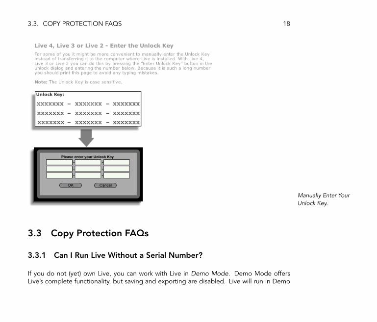
OR it might be more convenient to print the webpage with the Unlock Key on it. On thetarget computer, press the Enter Unlock Key button to open a dialog with �elds for typingin the Unlock Key. Typing it in is easier than it �rst appears, because the �elds will turn redif you type the wrong string.
3.3. COPY PROTECTION FAQS 18
Manually Enter YourUnlock Key.
3.3 Copy Protection FAQs
3.3.1 Can I Run Live Without a Serial Number?
If you do not (yet) own Live, you can work with Live in Demo Mode. Demo Mode offersLive's complete functionality, but saving and exporting are disabled. Live will run in Demo

3.3. COPY PROTECTION FAQS 19
Mode by default if it has not been authorized.
Click Here if You AreInterested in BuyingLive.
If running Live in Demo Mode raises your interest in purchasing the full version of Live,please select Live from the Products Preferences tab and then click the Buy button, orvisit the Ableton webshop4. This site contains information about Ableton's distributor anddealer network. It also offers you the opportunity to buy Live online. Live's Preferences areavailable via the Options menu (or the Live menu in Mac OS X).
3.3.2 What if I Change My Computer's Components?
If the Challenge Code of your computer changes for some reason, Live will indeed askyou to unlock the software another time (see Can I Unlock Live More than Once?). TheChallenge Code does not change, however, when computer peripherals are replaced (audio
4http://www.ableton.com/shop

3.3. COPY PROTECTION FAQS 20
or MIDI hardware, printers, modems). The Challenge Code may change if the motherboard,processor or network card is replaced. On some computers, reformatting a hard drive alsochanges the Challenge Code.
3.3.3 Can I Unlock Live More than Once?
The standard Live license allows you to use Live on only one computer at a time. However,if you have registered your product5, the Ableton server will provide you with two UnlockKeys in good faith that you will use Live on only one machine at a time. Just proceed asdescribed in the corresponding section (see Step 2: Unlocking Live).
You can therefore run Live on both a studio desktop computer and a tour laptop, but not atthe same time.
Should the Ableton server reject your demand for another Unlock Key, please contactAbleton's technical support.
They can be reached by:
� E-mail6;
� Telephone: +49 (0)30 - 288 763 151 (available Monday to Friday 11 to 15hrs CET);
� Fax: +49 (0)30 - 288 763 11.
To speed up the process, please:
� Register your copy of Live7;
� Include a brief explanation of the circumstances.
5http://www.ableton.com/[email protected]://www.ableton.com/register

3.3. COPY PROTECTION FAQS 21
To use Live on more than one computer at a time, you require a secondary license or a sitelicense. Ableton offers these licenses at special rates. Please contact the sales team8 fordetails.
3.3.4 Can I Play my Set from a Computer That Is Not Unlocked?
In Demo Mode, you can load and perform a Live Set with no time limitation. You cannot,however, save or export your work. When you go on tour, consider taking along your Liveprogram CD and a CD with the last state of your Live Set(s). In case of an emergency, youcan install and run Live on any computer available and play your backup Live Set(s).
3.3.5 Can I Hide Products or Features if I'm Not Ready to PurchaseThem?
In the Products tab of the Preferences, you can view your available products and theirstatuses (e.g., Demo Mode, Unlocked, etc.). Clicking on any product will provide you withmore information and the option of buying or unlocking.
If you are not ready to purchase a particular product, you can hide it and its features fromview in Live using the Hide button. If hidden, a product and its features will be unavailable.You can always choose to show a product again later, and then try out its features by usingthem in Demo Mode.

3.3. COPY PROTECTION FAQS 22
Click Here to Hide aProduct's Features.
3.3.6 What Do I Do About Problems or Questions Regarding Copy Pro-tection?
Please contact technical support9. They are happy to help!

Chapter 4
Live Basics
This chapter introduces the essential concepts of Live. We advise you to read this chapterearly in your Live career, as a solid understanding of the program's basic principles will helpyou fully exploit Live's potential for your music-making.
4.1 Live Sets
The type of document that you create and work on in Live is called a Live Set (see Live Sets).Live Sets can be opened either through the File menu's Open command or via the built-inFile Browsers.
23

4.2. ARRANGEMENT AND SESSION 24
A Live Set in theBrowser, Accessed viathe Library Button.
Pressing the Library button in Live's Browser will take you to Live's library of creative tools.There are a number of starter Sets here; double-clicking a Live Set's name in the Browserwill open that Live Set.
4.2 Arrangement and Session
The basic musical building blocks of Live are called clips. A clip is a piece of musical material:a melody, a drum pattern, a bass line or a complete song. Live allows you to record andalter clips, and to create larger musical structures from them: songs, remixes, DJ sets orstage shows.
A Live Set consists of two environments that can hold clips: The Arrangement is a layout ofclips along a musical timeline; the Session is a real-time-oriented �launching base� for clips.Every Session clip has its own play button that allows launching the clip at any time and inany order. Each clip's behavior upon launch can be precisely speci�ed through a number ofsettings (see Launching Clips).
Clips in the Session View(Left) and in theArrangement View(Right).
The Arrangement is accessed via the Arrangement View (see Arrangement View) and the

4.3. TRACKS 25
Session via the Session View (see Session View); you can toggle between the two viewsusing the computer's Tab key or their respective selectors. Because the two views havedistinct applications, they each hold individual collections of clips. However, it is importantto understand that �ipping the views simply changes the appearance of the Live Set anddoes not switch modes, alter what you hear or change what is stored.
The Arrangement andSession View Selectors.
Arrangement and Session interact in useful (though potentially confusing) ways. One can, forinstance, improvise with Session clips and record a log of the improvisation (see RecordingSessions into the Arrangement) into the Arrangement for further re�nement. This worksbecause Arrangement and Session are connected via tracks.
4.3 Tracks
Tracks host clips and also manage the �ow of signals, the creation of new clips throughrecording, sound synthesis, effects processing and mixing.

4.3. TRACKS 26
A Track in theArrangement View.
Session and Arrangement share the same set of tracks. The tracks are vertically laid out fromleft to right in the Session View, and horizontally from top to bottom in the ArrangementView. A simple rule governs the cohabitation of clips in a track:
A track can only play one clip at a time.
Therefore, one usually puts clips that should play alternatively in the same Session Viewcolumn, and spreads out clips that should play together across tracks in rows, or so-calledscenes (see Tracks and Scenes).
A Scene in the SessionView.
The exclusivity of clips in a track also implies that, at any on time, a track will either play aSession clip or an Arrangement clip, but never both. So, who wins? When a Session clipis launched, the respective track stops whatever it is doing to play that clip. In particular, ifthe track was playing an Arrangement clip, it will stop it in favor of the Session clip � evenas the other tracks continue to play what is in the Arrangement. The track will not resume
4.4. AUDIO AND MIDI 27
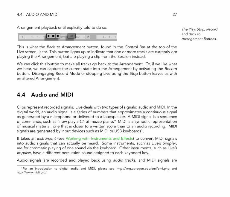
Arrangement playback until explicitly told to do so. The Play, Stop, Recordand Back toArrangement Buttons.
This is what the Back to Arrangement button, found in the Control Bar at the top of theLive screen, is for. This button lights up to indicate that one or more tracks are currently notplaying the Arrangement, but are playing a clip from the Session instead.
We can click this button to make all tracks go back to the Arrangement. Or, if we like whatwe hear, we can capture the current state into the Arrangement by activating the Recordbutton. Disengaging Record Mode or stopping Live using the Stop button leaves us withan altered Arrangement.
4.4 Audio and MIDI
Clips represent recorded signals. Live deals with two types of signals: audio and MIDI. In thedigital world, an audio signal is a series of numbers that approximates a continuous signalas generated by a microphone or delivered to a loudspeaker. A MIDI signal is a sequenceof commands, such as �now play a C4 at mezzo piano.� MIDI is a symbolic representationof musical material, one that is closer to a written score than to an audio recording. MIDIsignals are generated by input devices such as MIDI or USB keyboards1.
It takes an instrument (see Working with Instruments and Effects) to convert MIDI signalsinto audio signals that can actually be heard. Some instruments, such as Live's Simpler,are for chromatic playing of one sound via the keyboard. Other instruments, such as Live'sImpulse, have a different percussion sound assigned to each keyboard key.
Audio signals are recorded and played back using audio tracks, and MIDI signals are
1For an introduction to digital audio and MIDI, please see http://img.uoregon.edu/emi/emi.php andhttp://www.midi.org/

4.5. AUDIO CLIPS AND SAMPLES 28
recorded and played back using MIDI tracks. The two track types have their own corre-sponding clip types. Audio clips cannot live on MIDI tracks and vice versa.
Information about inserting, reordering and deleting audio and MIDI tracks is found here(see Audio and MIDI Tracks).
4.5 Audio Clips and Samples
An audio clip contains a reference to a sample (also known as a �sound �le� or �audio �le�)or a compressed sample (such as an MP3 �le). The clip tells Live where on the computer'sdrives to �nd the sample, what part of the sample to play and how to play it.
When a sample is dragged in from one of Live's built-in File Browsers (see Working with theFile Browsers), Live automatically creates a clip to play that sample. Prior to dragging in asample, one can audition or preview it directly in the Browser; the switch in the Browser withthe headphone icon activates previewing.
Samples Are Dragged infrom Live's File Browsers.
Live offers many options for playing samples in exciting new ways, allowing you to create an

4.5. AUDIO CLIPS AND SAMPLES 29
abundance of new sounds without actually changing the original sample � all the changesare computed in real time, while the sample is played. The respective settings are made inthe Clip View (see Clip View), which appears on screen when a clip is double-clicked.
An Audio Clip'sProperties as Displayedin the Clip View.
Many powerful manipulations arise from Live's warping (see Time-Warping Samples) capa-bilities. Warping means changing the speed of sample playback independently from thepitch so as to match the project tempo as adjusted in the Control Bar's Tempo Field.
The Control Bar's TempoField.
The most elementary use of this technique, and one that usually requires no manual setup,is synchronizing sample loops to the chosen tempo. Live's Auto-Warp algorithm actuallymakes it easy to line up any sample with the project tempo, such as a recording of a drunkjazz band's performance. It is also possible to radically change the sonic signature of asound using extreme warp settings.
4.6. MIDI CLIPS AND MIDI FILES 30
4.6 MIDI Clips and MIDI Files
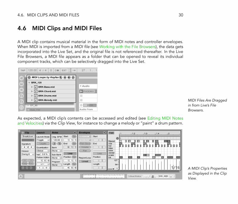
A MIDI clip contains musical material in the form of MIDI notes and controller envelopes.When MIDI is imported from a MIDI �le (see Working with the File Browsers), the data getsincorporated into the Live Set, and the original �le is not referenced thereafter. In the LiveFile Browsers, a MIDI �le appears as a folder that can be opened to reveal its individualcomponent tracks, which can be selectively dragged into the Live Set.
MIDI Files Are Draggedin from Live's FileBrowsers.
As expected, a MIDI clip's contents can be accessed and edited (see Editing MIDI Notesand Velocities) via the Clip View, for instance to change a melody or �paint� a drum pattern.
A MIDI Clip's Propertiesas Displayed in the ClipView.

4.7. DEVICES AND THE MIXER 31
4.7 Devices and the Mixer
A track can have not only clips but also a chain of devices (see Working with Instrumentsand Effects) for processing signals. Double-clicking a track's title bar brings up the TrackView, which shows the track's device chain.
The Track ViewDisplaying an AudioTrack's Device Chain.
Live's built-in audio effects (see Live Audio Effect Reference), MIDI effects (see Live MIDIEffect Reference) and instruments (see Live Instrument Reference) are available from theDevice Browser and can be dragged from there into the Track View or onto a track title bar.

4.7. DEVICES AND THE MIXER 32
Live's Built-in DevicesAre Available from theDevice Browser.
You can also use plug-in devices (see Using Plug-Ins) in Live. VST and Audio Units (Mac OSX only) Plug-ins are available from the Plug-In Device Browser.
Plug-In Devices AreAvailable from thePlug-In Device Browser.
Consider an audio clip playing in an audio track. The audio signal from the clip reaches theleftmost device in the chain. This device processes (changes) the signal and feeds the resultinto the next device, and so on. The number of devices per track is theoretically unlimited.

4.7. DEVICES AND THE MIXER 33
In practice, the computer's processor speed does impose a limit on the number of devicesyou can use at the same time, a topic that deserves separate discussion (see Managing theCPU Load). Note that the signal connections between audio devices are always stereo, butthe software's inputs and outputs can be con�gured to be mono in the Audio Preferences.
When the signal has passed through the device chain, it ends up in Live's mixer (see The LiveMixer). As Session and Arrangement share the same set of tracks, so they share the mixer.The mixer can be shown in both views for convenience. To optimize the screen layout, theindividual mixer sections can be shown or hidden using the View menu's entries.

4.7. DEVICES AND THE MIXER 34
The Live Mixer in theArrangement View (Top)and Session View(Bottom).
The mixer has controls for volume, pan position and sends, which adjust the contributioneach clip track makes to each return track's input. Return tracks cannot host clips, onlyeffects. Via their sends, all tracks can feed a part of their signal into a return track and shareits effects.
The mixer also includes a crossfader (see Using Live's Crossfader), which can create smoothtransitions between clips playing on different tracks. Live's crossfader works like a typical DJmixer crossfader, except that it allows crossfading not only two but any number of tracks �
4.7. DEVICES AND THE MIXER 35
including the returns.
Live's Crossfader.
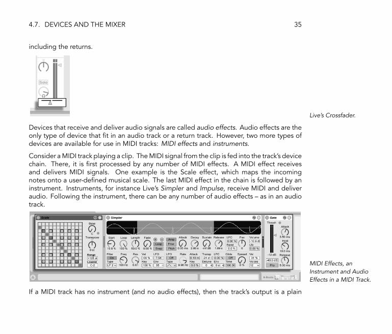
Devices that receive and deliver audio signals are called audio effects. Audio effects are theonly type of device that �t in an audio track or a return track. However, two more types ofdevices are available for use in MIDI tracks: MIDI effects and instruments.
Consider a MIDI track playing a clip. The MIDI signal from the clip is fed into the track's devicechain. There, it is �rst processed by any number of MIDI effects. A MIDI effect receivesand delivers MIDI signals. One example is the Scale effect, which maps the incomingnotes onto a user-de�ned musical scale. The last MIDI effect in the chain is followed by aninstrument. Instruments, for instance Live's Simpler and Impulse, receive MIDI and deliveraudio. Following the instrument, there can be any number of audio effects � as in an audiotrack.
MIDI Effects, anInstrument and AudioEffects in a MIDI Track.
If a MIDI track has no instrument (and no audio effects), then the track's output is a plain

4.8. PRESETS AND DEVICE GROUPS 36
MIDI signal, which has to be sent somewhere else to be converted into audio. In this case,the track's mix and Send controls disappear from the mixer.
The Mixer for a MIDITrack without anInstrument.
4.8 Presets and Device Groups
Every Live device can store and retrieve particular sets of parameter values as presets (seeLive Device Presets). As presets are stored independently from Live Sets, new presetsbecome part of a library that any project can draw from.
Live's Device Groups (see Device Groups) allow saving combinations of devices and theirsettings as a single preset. This feature allows for the creation of powerful multi-devicecreations and effectively adds all the capabilities of Live's MIDI and audio effects to thebuilt-in instruments.

4.9. ROUTING 37
4.9 Routing
As we have seen, all tracks deliver signals, either audio or MIDI. Where do these signalsgo? This is set up in the mixer's In/Out section, which offers, for every track, choosers toselect a signal source and destination. The In/Out section, accessible through the Viewmenu's �In/Out� entry, is Live's �patchbay.� Its routing options (see Routing and I/O) enablevaluable creative and technical methods such as resampling, submixing, layering of synths,complex effects setups and more.
Track Routing Is Set upUsing the In/Out Sectionin the Arrangement(Top) or Session View(Bottom).
Signals from the tracks can be sent to the outside world via the computer's audio and MIDI

4.10. RECORDING NEW CLIPS 38
interfaces, to other programs that are connected to Live via ReWire (see Connecting viaReWire) or to other tracks or devices within Live.
Likewise, a track can be set up to receive an input signal to be played through the track'sdevices. Again, tracks can receive their input from the outside, from a ReWire program orfrom another track or device in Live. The Monitor controls regulate the conditions underwhich the input signal is heard through the track.
4.10 Recording New Clips
Audio tracks and MIDI tracks can record their input signal and thereby create new clips(see Recording New Clips). Recording is enabled on a track by pressing its Arm button(Hold down the Ctrl (PC) / (Mac) modi�er to arm several tracks at once). Whenthe Control Bar's Record button is on, every armed track records its input signal into theArrangement. Every take yields a new clip per track.
A Track Arm Button, asAppears in the SessionView.
It is also possible to record into Session View slots on the �y (see Recording Into SessionSlots). This technique is very useful for the jamming musician, as Session recording doesnot require stopping the music. When a track is armed, its Session slots exhibit Clip Recordbuttons, and clicking one of these commences recording. Clicking the Clip Record buttonagain de�nes the end of the recording and launches the new clip. As these actions aresubject to real-time launch quantization, the resulting clips can be automatically cut to thebeat.

4.11. AUTOMATION ENVELOPES 39
The Control Bar'sQuantization Chooser.
Session recording in conjunction with the Overdub option and Record Quantization is themethod of choice for creating drum patterns, which are built up by successively addingnotes to the pattern while it plays in a loop. It only takes a MIDI keyboard (or the computerkeyboard) and a MIDI track with Live's Impulse percussion instrument to do this (see OverdubRecording MIDI Patterns).
4.11 Automation Envelopes
Often, when working with Live's mixer and effects, you will want the controls' movementsto become part of the Arrangement. The movement of a control across the Arrangementtimeline is called automation (see Automation and Editing Envelopes); a control whosevalue changes in the course of this timeline is automated. Automation is represented in theArrangement View by breakpoint envelopes, which can be edited and drawn.
The Automated PanControl and itsEnvelope.
Practically all mixer and effect controls in Live can be automated, even the song tempo.Creating automation is straightforward: All changes of a control that occur while the ControlBar's Record switch is on become automation.
Changing an automated control's value while not in Record Mode is similar to launching aSession clip while the Arrangement is playing: It deactivates the control's automation (in
4.12. CLIP ENVELOPES 40
favor of the new control setting). The control will stop tracking its automation and restwith the new value until the Back to Arrangement button is pressed, which will resumeArrangement playback.
4.12 Clip Envelopes
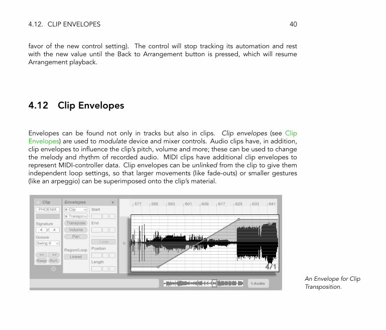
Envelopes can be found not only in tracks but also in clips. Clip envelopes (see ClipEnvelopes) are used to modulate device and mixer controls. Audio clips have, in addition,clip envelopes to in�uence the clip's pitch, volume and more; these can be used to changethe melody and rhythm of recorded audio. MIDI clips have additional clip envelopes torepresent MIDI-controller data. Clip envelopes can be unlinked from the clip to give themindependent loop settings, so that larger movements (like fade-outs) or smaller gestures(like an arpeggio) can be superimposed onto the clip's material.
An Envelope for ClipTransposition.

4.13. MIDI AND KEY REMOTE 41
4.13 MIDI and Key Remote
To liberate the musician from the mouse, most of Live's controls can be �remote-controlled�via an external MIDI controller. Remote mappings are established in MIDI Map Mode (seeAssigning MIDI Remote Control), which is engaged by pressing the MIDI switch in theControl Bar.
In this mode, you can click on any mixer or effect control, and then assign it to a controllersimply by sending the desired MIDI message (for example, by turning a knob on your MIDIcontrol box). Your assignments take effect immediately after you leave MIDI Map Mode.Session clips can be mapped to a MIDI key or even a keyboard range for chromatic playing.
MIDI keys and controllers that have been mapped to Live's controls are not available forrecording via MIDI tracks. These messages are �ltered out before the incoming MIDI ispassed on to the MIDI tracks.
The Key/MIDI MapControls.
Session clips, switches, buttons and radio buttons can be mapped to computer keyboardkeys as well. This happens in Key Map Mode (see Keyboard Remote Control), which worksjust like MIDI Map mode.
Live offers, in addition to this general purpose mapping technique, dedicated support forMackie Control-compatible mixer surfaces (see Mackie Control), which allows for mouse-freeoperation of the program.

4.14. SAVING AND EXPORTING 42
4.14 Saving and Exporting
Saving a Live Set saves everything it contains, including all clips, their positions and settings,and settings for devices and controls. An audio clip can, however, lose the reference to itscorresponding sample if it is moved or deleted from disk. The links between samples andtheir clips can be preserved with a special command, the Save Set Self-Contained command(see The Sounds Folder and Self-Containing), which makes a copy of each sample and storesit in a �Sounds� folder along with the Live Set.
A separate Save button in the Clip View saves a set of default clip settings (see SavingDefault Clip Settings with the Sample) along with the sample, so that each time the sample isdragged into the program, it will automatically appear with these settings. This is especiallyuseful if you have made warp settings for a clip and want to use it in multiple Live Sets.
Exporting audio from Live can be done from both the Session and Arrangement Views.Live will export the audio coming through on the Master output as an audio �le of yourspeci�cations via Render to Disk (see Exporting Audio).
Live can also export individual MIDI clips as MIDI �les (see Exporting MIDI Files).
Exporting and saving material for later use in Live can be done very conveniently with theLive Clip format. Session View clips can be dragged back out of a Live Set to the FileBrowsers, and thereby exported to disk as Live Clips (see Live Clips).

4.14. SAVING AND EXPORTING 43
A Live Clip in the FileBrowser.
Live Clips are a very powerful way of storing ideas, as they save not only the clip's Clip Viewsettings, but also the corresponding track's instruments and effects chain. Live Clips in theBrowser can be previewed and added to any open Live Set just like sample �les. In the LiveSet, they restore the original clip's creative options.
Using Live Clips, you can build your own personalized library of:
� MIDI sequences with matching instruments and effects, e.g., a MIDI drum pattern withthe associated Impulse and effects settings;
� Different regions or loops (see Sample Loop/Region and Display) referencing the samesource �le;
� Variations of a sample loop created by applying Warp Markers (see Time-WarpingSamples), clip envelopes (see Clip Envelopes) and effects (see Working with Instru-ments and Effects);
� Ideas that may not �t your current project but could be useful in the future.
4.15. THE LIBRARY 44
4.15 The Library
Live comes with a library of sound ideas that can serve as a starting point for your owncreations.
The �rst part of the library is a large preset collection for Live instruments and effects,accessible through the Live Device Browser (see Browsing and Loading Presets).
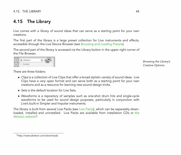
The second part of the library is accessed via the Library button in the upper right corner ofthe File Browser.
Browsing the Library'sCreative Options.
There are three folders:
� Clips is a collection of Live Clips that offer a broad stylistic variety of sound ideas. LiveClips have a very open format and can serve both as a starting point for your owncreations and as a resource for learning new sound design tricks.
� Sets is the default location for Live Sets.
� Waveforms is a repository of samples such as one-shot drum hits and single-cyclewaveforms to be used for sound design purposes, particularly in conjunction withLive's built-in Simpler and Impulse instruments.
The library is built from several Live Packs (see Live Packs), which can be separately down-loaded, installed and uninstalled. Live Packs are available from installation CDs or theAbleton website2.
2http://www.ableton.com/downloads

Chapter 5
Managing Files and Sets
Various types of �les are used in making music with Live, from those containing MIDI (seeMIDI Files) and audio (see Sample Files), to more program-speci�c �les such as Live Clips(see Live Clips) and Live Sets (see Live Sets). This chapter will explain everything you needto know about working with each of these �le types in Live. However, we should �rst take alook at Live's File Browsers, through which most �les arrive in the program.
5.1 Working with the File Browsers
5.1.1 Browsing the Folder Hierarchy
Files are browsed and imported from disk using Live's on-board Browsers, which can bepointed to any folder location on the computer. The Browsers can also be searched based
45

5.1. WORKING WITH THE FILE BROWSERS 46
on speci�c criteria, a topic that we will cover in the next section (see Searching for Files).
Each File Browser can have its own root directory, shown at the top of the Browser, thecontents of which are available for browsing below.
�Library� Is thisBrowser's Root.
The Browser root can easily be changed: The Folder-Up button moves the Browser root onestep up in the disk hierarchy.
The File Browser'sFolder-Up Button.
You can also set the Browser root to any folder in the Browser by selecting the folder andclicking the Root button, double-clicking the folder, or pressing Return . Note that there arethree File Browsers that you can set up to point to commonly used folders.
The File Browser's RootButton.
To set the root of the Browser to Live's library (see The Library) of clips, Sets and presets, usethe Library button just to the right of the Root button, or the Set Root To Library (PC) /
Ctrl (Mac) context menu command.
The Library Button.
Moving through the �les in Live's Browser can be done with either the mouse or the computerkeyboard:
� Scroll up and down in the Browser with and .

5.1. WORKING WITH THE FILE BROWSERS 47
� Close and open folders with and .
� Jump to the parent folder of any closed folder using . (Hint: If executed on atop-level folder, this is an alternative to pressing the Folder-Up button, and will movethe Browser root up one level.)
To clean up the Browser, use (PC) / Ctrl (Mac) to access the context menu, andthen select the Close All Folders option to show only top-level folders. Double-clicking anyof the three File Browser icons will also close all sub-level folders.
Double-Click TheseIcons to Clean up theBrowser.
Note that you may occasionally want to refresh the Browser if you are working on a network.To do so, (PC) / Ctrl (Mac) to open the context menu, and then select the Refreshcommand.
5.1.2 Searching for Files
Live's File Browsers are equipped with a search function for �nding �les. Clicking theSearch button in the upper right corner of the Browser or using the Ctrl F (PC) /
F (Mac) shortcut will open the Browser's Search Mode.
Activating BrowserSearch Mode.
5.1. WORKING WITH THE FILE BROWSERS 48
Live will search for the contents typed in the Search �eld throughout the entire Browserroot. Alternatively, you can search within a single folder in the Browser with the (PC) /
Ctrl (Mac) context menu's Search In Folder command.
After entering search criteria, begin the search by pressing Return on your computer key-board. Live will �nd �les that contain the search criteria in their name or suf�x (e.g., �.wav�).
The search results will also include �les that contain the entered criteria in any part of their �lepath. This means that a search for �bass,� for example, will yield not only �les with namescontaining the word �bass� but also those located in folders with names containing theword �bass.� Compressed sample metadata tags are also included in the search, making itpossible to search for songs from a speci�c album or artist, for example. Searching �le pathsand metadata can be deactivated with the Search In Path and Search In Metadata settings,available in Live's Options menu or via the context menu. The names of MIDI tracks withinmultitrack MIDI �les are also included in searches.
Note that the �rst search of any folder will always take longer than subsequent searches, asLive creates an index of the folder's contents to facilitate ef�cient searching.
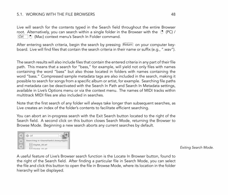
You can abort an in-progress search with the Exit Search button located to the right of theSearch �eld. A second click on this button closes Search Mode, returning the Browser toBrowse Mode. Beginning a new search aborts any current searches by default.
Exiting Search Mode.
A useful feature of Live's Browser search function is the Locate In Browser button, found tothe right of the Search �eld. After �nding a particular �le in Search Mode, you can selectthe �le and click this button to open the �le in Browse Mode, where its location in the folderhierarchy will be displayed.

5.1. WORKING WITH THE FILE BROWSERS 49
The Locate In BrowserButton.
5.1.3 Previewing Files
The Preview Switch.
Live allows you to preview �les in the File Browser before they are imported into the program.Previewing is activated using the Browser's Preview switch.
Click on the �les (or use and ) to select and listen to them.
You can adjust the previewing volume using the Preview Volume knob in the mixer.
The Preview VolumeKnob.
If your audio hardware offers multiple audio outs, you can privately audition, or cue, �lesvia headphones connected to a separate pair of outs � while the music continues to play.To learn how to set up Live for cueing, please refer to the appropriate manual section (seeSoloing and Cueing).
Hint: You can preview �les even when the Preview switch is not activated by pressing .

5.1. WORKING WITH THE FILE BROWSERS 50
5.1.4 Adding Clips from the Browser
There are several ways to add clips to a Live Set:
� Files can be dragged and dropped from the File Browsers into tracks in the Session orArrangement View. Dragging and dropping material from the Browser into the spaceto the right of Session View tracks or below Arrangement View tracks will create a newtrack and place the new clip(s) there.
Dropping a Clip toCreate a New Track.
� In the Session View, double-clicking or pressing Return on a �le in the Browser willautomatically create a new track to the right of the other tracks and load it with theclip.
� Files can be dropped directly into Live from the Explorer (Windows) / Finder (Mac).
5.1.5 File Maintenance in the Browser
You can use Live's File Browsers for all of the �le maintenance activities that you are familiarwith on your operating system.
� Move �les and folders by dragging and dropping, or by copying/cutting and pasting.Copying, cutting and pasting can be done with either Edit menu commands or key-board shortcuts (see Editing). A �le can be moved from one File Browser to another

5.2. SAMPLE FILES 51
by dragging it over the target Browser's button.
� Rename �les and folders using the Edit menu's Rename command or the Ctrl R
(PC) / R (Mac) shortcut. Cancel renaming with the Esc key.
� Create folders by opening the context menu with (PC) / Ctrl (Mac), and thenselecting the Create Folder command.
� Delete �les and folders using the Edit menu's Delete command or your computer'sBackspace or Delete key. Deleting items within Live moves them to the system trash; ifnecessary, you can recover items from the system trash via your computer's operatingsystem.
Note that, while you can rename or delete entire MIDI �les (see MIDI Files) via the Browser,this is not possible with the individual MIDI tracks contained within them. This is also thecase with the individual components of Live Sets (see Live Sets).
5.2 Sample Files
A sample is a �le that contains audio data. Live can play both uncompressed �le formats(WAV, AIF and Sound Designer II for Mac) and compressed �le formats (MP3, Ogg Vorbis,Ogg FLAC and FLAC).
A note on using Variable Bit Rate (VBR) �les: Please install QuickTime for decoding purposesif you do not already have it on your system. It can be downloaded from the Apple website1.
As Live plays the samples directly from disk, you can work with a large number of (large)samples without running into RAM memory limitations.
Live can combine uncompressed mono or stereo samples of any length, sample rate orbit depth without prior conversion. To play a compressed sample, Live decodes (see The
1http://www.apple.com/quicktime/download/mac.html

5.2. SAMPLE FILES 52
Decoding Cache) the sample and writes the result to a temporary, uncompressed sample�le. This usually happens quickly enough that you will be able to play the sample right away,without waiting for the decoding process to �nish.
Note: When adding a long sample to a project, Live might tell you that it cannot play thesample before it has been analyzed. Please see the section on analysis (see Analysis Files(.asd)) for an explanation.
5.2.1 The Decoding Cache
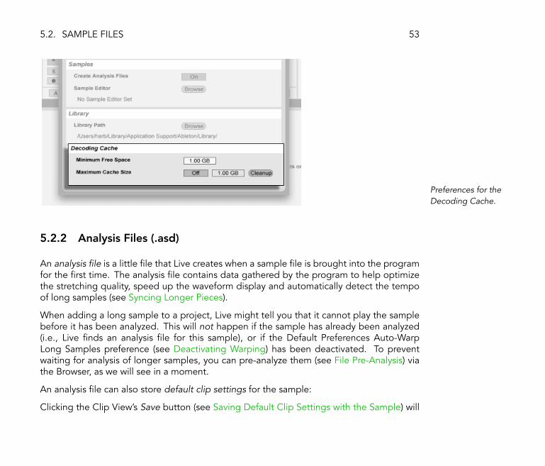
To save computational resources, Live keeps the decoded sample �les of compressedsamples in the decoding cache, a sub-directory of the Audio Record Folder (see Setting upFile Types). Maintenance of the cache is normally not required, as Live automatically deletesolder �les to make room for those that are new. You can, however, impose limits on thecache size using the Misc Preferences' Decoding Cache section. The cache will not growlarger than the �Maximum Cache Size� setting, and it will always leave the �Minimum FreeSpace� on the hard disk. Pressing the Cleanup button in the Decoding Cache preferenceswill delete all �les not being used by the current Live Set.
5.2. SAMPLE FILES 53
Preferences for theDecoding Cache.
5.2.2 Analysis Files (.asd)
An analysis �le is a little �le that Live creates when a sample �le is brought into the programfor the �rst time. The analysis �le contains data gathered by the program to help optimizethe stretching quality, speed up the waveform display and automatically detect the tempoof long samples (see Syncing Longer Pieces).
When adding a long sample to a project, Live might tell you that it cannot play the samplebefore it has been analyzed. This will not happen if the sample has already been analyzed(i.e., Live �nds an analysis �le for this sample), or if the Default Preferences Auto-WarpLong Samples preference (see Deactivating Warping) has been deactivated. To preventwaiting for analysis of longer samples, you can pre-analyze them (see File Pre-Analysis) viathe Browser, as we will see in a moment.
An analysis �le can also store default clip settings for the sample:
Clicking the Clip View's Save button (see Saving Default Clip Settings with the Sample) will
5.2. SAMPLE FILES 54
store the current clip's settings with the sample's analysis �le. The next time the sample isdragged into Live, it will appear with all its clip settings intact. This is particularly usefulfor retaining Warp Marker settings (see Time-Warping Samples) with the sample. Storingdefault clip settings with the analysis �le is different from saving the clip as a Live Clip, asdescribed in the relevant section (see Live Clips).
The analysis �le's name is the same as that of the associated sample, with an added �.asd�extension. Live puts this analysis �le in the same folder as the sample.
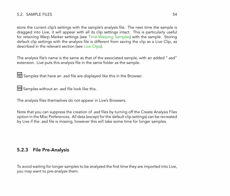
Samples that have an .asd �le are displayed like this in the Browser.
Samples without an .asd �le look like this.
The analysis �les themselves do not appear in Live's Browsers.
Note that you can suppress the creation of .asd �les by turning off the Create Analysis Filesoption in the Misc Preferences. All data (except for the default clip settings) can be recreatedby Live if the .asd �le is missing, however this will take some time for longer samples.
5.2.3 File Pre-Analysis
To avoid waiting for longer samples to be analyzed the �rst time they are imported into Live,you may want to pre-analyze them.

5.2. SAMPLE FILES 55
Pre-Analyzing AudioFiles.
To pre-analyze all the �les contained in any folder in the Browser, use the (PC) / Ctrl
(Mac) context menu's Analyze Audio command. This process can also be cancelled via thecontext menu.
5.2.4 Exporting Audio
The File menu's Render to Disk command allows exporting Live's Master audio output as anew sample. The resulting �le can be used to burn an audio CD for listening purposes ora data CD, which could serve as a backup of your work or be used with other digital audioapplications.
Which Signal Will Be Rendered?
Render to Disk will always render the signal at Live's Master output. If you are monitoringthe Master output, you can be sure that the rendered �le will contain exactly what you hear.To export individual tracks, deactivate all tracks other than the ones you want to export byturning off their Track Activator switches (see The Live Mixer) in the mixer.

5.2. SAMPLE FILES 56
When Render to Disk is invoked while the Arrangement View is up, Live will render theselected time range.
If you would like to render the current Arrangement loop, choose the Select Loop commandfrom the Edit menu prior to choosing Render to Disk. Keep in mind that the selection oftracks is irrelevant: The signal to be rendered is the Master output.
If you choose Render to Disk while the Session View is up, Live will ask you to specify thelength of the sample to be rendered. The Render to Disk dialog will come up with a bars-beats-sixteenths �eld where you can type in the desired length. Live will capture audio fromthe Master output starting at the current play start position for whichever duration you havespeci�ed.
Rendering Options
The Render to Disk command opens a dialog that offers several rendering options:
� Normalize. If this is activated, the sample resulting from the render process will benormalized (i.e., the �le will be ampli�ed so that the highest peak attains the maximumavailable headroom).
� Render as Loop. If this is activated, Live will create a sample that can be used as aloop. For example, suppose your Live Set uses a delay effect. If Render as Loop is on,Live will go through the rendering process twice: The �rst pass will not actually writesamples to disk, but add the speci�ed delay effect. As the second pass starts writingaudio to disk, it will include the delay �tail� resulting from the �rst pass.
� File Type, Bit Depth, Sample Rate. These options specify the type of sample to becreated.
� Create Analysis File. If this is activated, Live will create an .asd �le that contains analysisinformation about the rendered sample. If you intend to use the new sample in Live,check this option.

5.3. MIDI FILES 57
� Convert to Mono. If this is activated, Live will create a mono �le instead of a stereo�le.
5.3 MIDI Files
A MIDI �le contains commands that prompt MIDI-compatible synthesizers or instruments,such as Live's Simpler (see Simpler), to create speci�c musical output. MIDI �les are exportedby hardware and software MIDI sequencers. Importing MIDI �les into Live works differentlythan with samples: MIDI �le data is incorporated into the Live Set, and the resulting MIDIclips lose all reference to the original �le. MIDI �les appear as folders in the File Browser;opening the folders gives you access to the �le's individual tracks (also called �voices� or�instruments�).
A MIDI File and ItsTracks in the Browser.
5.4. LIVE CLIPS 58
5.3.1 Exporting MIDI Files
Live MIDI clips can be exported as Standard MIDI �les. To export a MIDI clip, use the Filemenu's Export Selected MIDI Clip command. This command will open a �le-save dialog,allowing you to choose the location for your new MIDI �le.
Exporting a MIDI �le is different from saving the clip as a Live Clip, as described in therelevant section (see Live Clips).
5.4 Live Clips
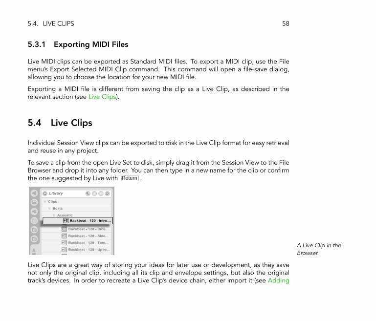
Individual Session View clips can be exported to disk in the Live Clip format for easy retrievaland reuse in any project.
To save a clip from the open Live Set to disk, simply drag it from the Session View to the FileBrowser and drop it into any folder. You can then type in a new name for the clip or con�rmthe one suggested by Live with Return .
A Live Clip in theBrowser.
Live Clips are a great way of storing your ideas for later use or development, as they savenot only the original clip, including all its clip and envelope settings, but also the originaltrack's devices. In order to recreate a Live Clip's device chain, either import it (see Adding

5.5. LIVE SETS 59
Clips from the Browser) into a track containing no clips or devices, or drag it into the spacein the Session or Arrangement View containing no tracks. Note that Live Clips that areimported into tracks already containing devices or clips will appear with their clip settingsbut not their devices. You could, for instance, drop a bass line Live Clip on an existing trackthat drives a bass instrument rather than creating a new track.
Clips belonging to any Live Sets already on disk are also Live Clips. Please see the sectionon importing and exporting Sets (see Importing and Exporting Sets with the Browser) formore on this topic.
Note that storing default clip settings (see Saving Default Clip Settings with the Sample) witha sample's analysis �le is different from saving a Live Clip. The default clip in the .asd �leannotates the sample with sensible default values (warp, gain and pitch settings) so that itwill play in a de�ned way when it is added to a Set. Live Clips, on the other hand, are storedon disk as separate musical ideas. For example, you could create a number of variationsfrom the same audio clip by using different warp, pitch, envelope and effect settings, andstore them all as separate Live Clips. In the Browser, you could then independently sort andpreview these clips, even though they are all referring to the same source sample.
5.5 Live Sets
The type of document that you create and work on in Live is called a Live Set.
5.5.1 Creating, Opening and Saving Sets
Use the File menu's New command to create new Live Sets, and the Open or Open Recentcommand to open existing ones. In the File Browser, you can double-click or press Return
on a Live Set to open it.
5.5. LIVE SETS 60
The File menu's Save command saves the current Live Set exactly as it is, including all clipsand settings.
You can also use the Save As command to save the current Live Set under a different nameand/or in a different directory location, or the Save a Copy command to create a copy ofthe current Live Set with a new name and/or new directory location.
Saving a Live Set leaves the samples referenced by that Live Set's clips in their currentlocations. If these �les are later moved, Live will attempt to help you �nd them (see Of�ineand Lost Files) when next you open that particular Live Set. The File menu's Save SetSelf-Contained command (see The Sounds Folder and Self-Containing) can help you avoidmissing �les altogether.
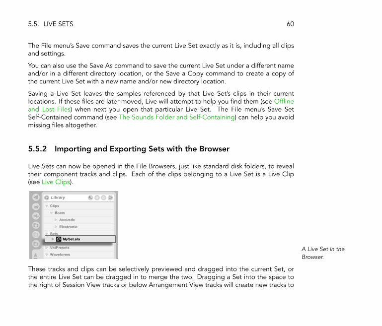
5.5.2 Importing and Exporting Sets with the Browser
Live Sets can now be opened in the File Browsers, just like standard disk folders, to revealtheir component tracks and clips. Each of the clips belonging to a Live Set is a Live Clip(see Live Clips).
A Live Set in theBrowser.
These tracks and clips can be selectively previewed and dragged into the current Set, orthe entire Live Set can be dragged in to merge the two. Dragging a Set into the space tothe right of Session View tracks or below Arrangement View tracks will create new tracks to

5.5. LIVE SETS 61
host the new content, whereas dragging a Set into existing tracks will replace any currentclips. Note that, if a Set is dragged into existing tracks containing clips or devices, its tracks'corresponding device chains will not be loaded.
You can export a selection of Session View clips as a new Live Set by dragging them to theFile Browser. To export a Set, �rst click and drag, or use the or Ctrl (PC) /(Mac) modi�ers, to select more than one Session View clip. Then, simply drag the clips toa folder in the File Browser, where you can either con�rm Live's suggested name or type inone of your own.
5.5.3 Template Sets
Use the Default Preferences' Template Save button to save the current Live Set as a template.Live will use these settings as the initialized, default state for new Live Sets. You can use thisto pre-con�gure:
� Your multichannel input/output setup.
� Preset devices, like EQs and Compressors, in every track.
� Computer key mappings (see Keyboard Remote Control).
� MIDI mappings (see MIDI Remote Control).
The template Live Set �Template.als� is located in Live's Preferences folder and can becopied or deleted from there. The easiest way to locate this folder is to search your disk for�Template.als.�
5.6. OFFLINE AND LOST FILES 62
5.6 Of�ine and Lost Files
If you load a Live Set or Live Clip that references samples missing from their referencedlocations, Live will issue a warning message and ask whether you want to locate the missing�les.
If you do not, the Live Set or Live Clip will open anyway, with the clips that reference missing�les marked �Of�ine.� Live will play silence in place of the of�ine clips.
You can �nd the missing �les by selecting of�ine clips and clicking the Clip View's Replacebutton (see Replacing the Clip's Sample).
5.7 The Sounds Folder and Self-Containing
The Sounds folder is a Live Set's private location for storing samples. All samples that arerecorded into a Live Set end up in this Live Set's Sounds folder. Live offers a convenientmethod for gathering all the �les that are referenced by a Live Set in this folder: When youchoose the File menu's Save Set Self-Contained command, Live copies all externally refer-enced �les there. After Live has self-contained the �les, there will no longer be referencesto samples spread over one or more hard drives. You can back up the Live Set along withits Sounds folder, or send it to collaborators via the Internet, and all �les used in the projectwill be included.
The Sounds folder for �My Live Set� is called �My Live Set Sounds.� It is located next to (inthe same folder as) �My Live Set.�

5.8. LIVE PACKS 63
5.8 Live Packs
Live's library (see The Library) is broken down into several Live Packs that can be separatelydownloaded, installed and uninstalled. A Live Pack is a single �le (much like a ZIP �le) thatexpands into many �les upon installation.
Live Packs are available from installation CDs or the Ableton website2. To install a down-loaded Live Pack, drag the �le into Live, double-click the �le, or select Install Live Pack fromthe File menu.
A list of all installed Live Packs is kept in the Preferences' Products tab. You can selectindividual Live Packs from the list and click the Uninstall button to remove them.
You can, of course, remove, rename, alter and add to the individual �les that come with LivePacks at will, making someone else's library your own.
2http://www.ableton.com/downloads
Chapter 6
Arrangement View
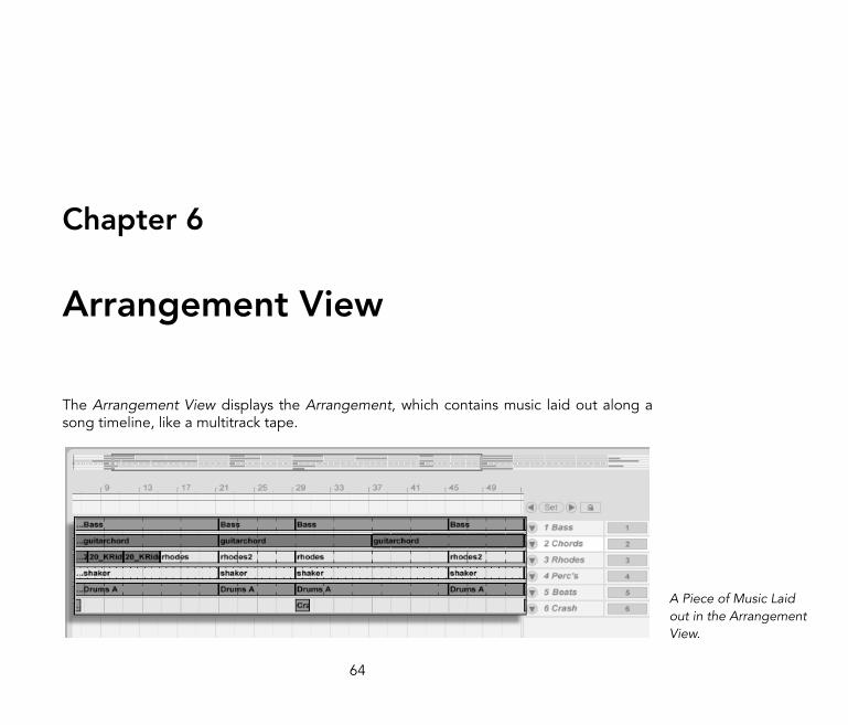
The Arrangement View displays the Arrangement, which contains music laid out along asong timeline, like a multitrack tape.
A Piece of Music Laidout in the ArrangementView.
64

6.1. NAVIGATION 65
The Arrangement View is a powerful editing tool that easily lets you combine and arrangemusical material of all types: MIDI, loops, sound effects and complete pieces of music.
6.1 Navigation
Live offers several fast methods for zooming and scrolling the Arrangement display:
1 3 4 56 2
Navigating theArrangement View.
1. To smoothly change the zoom level, click and drag vertically in the beat-timeruler at the top of the Arrangement View (you can also drag horizontally to scrollthe display).
2. To zoom in and out around the current selection, use the computer keyboard's +and - keys. To �pan� the display, click and drag while holding the Ctrl Alt
(PC) / Alt (Mac) modi�er.
3. The Arrangement Overview is like a �bird's-eye view� of your music. It alwaysshows the complete piece, from start to end. The black rectangular outline repre-

6.2. TRANSPORT 66
sents the part of the Arrangement that is currently displayed in the Arrangementdisplay below. To scroll the display, click within the outline and drag left or right;to zoom out and in, drag up and down.
4. To change the displayed part of the Arrangement, drag the outline's left andright edges.
5. To see a speci�c part of the Arrangement in more detail, click on it in the Overviewand drag downwards to zoom in around that part. Note that you can also draghorizontally to scroll the display. Using this method, you can zoom and scroll tofocus around any part of the Arrangement with just one mouse motion.
6. To have the Arrangement display follow the song position and scroll automati-cally, turn on the Follow switch, or use the Follow command from the Optionsmenu.
6.2 Transport
There are a number of ways to control Live's transport with the computer keyboard andmouse:
1. You can start Arrangement playback by clicking the Control Bar's Play button,and stop playback by clicking the Stop button. Arrangement playback can alsobe toggled on and off by pressing the keyboard's space bar.
The Play and StopButtons in the ControlBar.
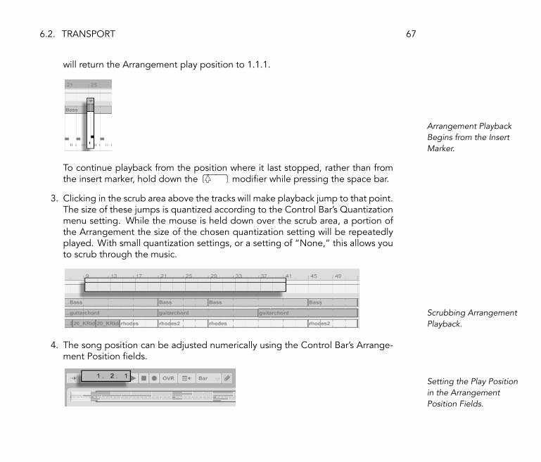
2. You can set the Arrangement playback position by clicking anywhere along theArrangement to place the �ashing insert marker. Double-clicking the Stop button
6.2. TRANSPORT 67
will return the Arrangement play position to 1.1.1.
Arrangement PlaybackBegins from the InsertMarker.
To continue playback from the position where it last stopped, rather than fromthe insert marker, hold down the modi�er while pressing the space bar.
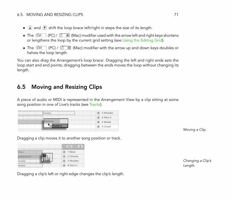
3. Clicking in the scrub area above the tracks will make playback jump to that point.The size of these jumps is quantized according to the Control Bar's Quantizationmenu setting. While the mouse is held down over the scrub area, a portion ofthe Arrangement the size of the chosen quantization setting will be repeatedlyplayed. With small quantization settings, or a setting of �None,� this allows youto scrub through the music.
Scrubbing ArrangementPlayback.
4. The song position can be adjusted numerically using the Control Bar's Arrange-ment Position �elds.
Setting the Play Positionin the ArrangementPosition Fields.

6.3. LAUNCHING THE ARRANGEMENT WITH LOCATORS 68
The Arrangement Position �elds show the song position in bars-beats-sixteenths.To change the values:
� Click and drag up or down in any of these �elds.
� Click and type a number, then hit Return .
� Click and decrement or increment the value with and .
5. Arrangement playback can be started at a particular point in one of your clipsusing the scrub area in the Clip View (see Clip View).
6. Several Arrangement playback positions can be set using launchable locators(see Launching the Arrangement with Locators).
Note that any computer keyboard key or MIDI message can be mapped to the transportcontrols, as described in the respective chapter (see MIDI and Key Remote Control).
6.3 Launching the Arrangement with Locators
Using Locators toLaunch Play in theArrangement.
Locators can be set at any point in the Arrangement. This can be done in real time duringplayback or recording with the Set Locator button, and will be quantized according to theglobal quantization value set in the Control Bar. Clicking the Set Locator button when the

6.3. LAUNCHING THE ARRANGEMENT WITH LOCATORS 69
Arrangement is not playing will create a locator at the insert marker or selection start. Youcan also create a locator using the context menu in the scrub area above the tracks or via theInsert menu. Note that the position of a new locator is quantized according to the ControlBar's Quantization menu setting.
The Locator Controls.
You can recall (jump to) locators by clicking on them, or with the Previous and Next Locatorbuttons on either side of the Set button. Locators can also be recalled using MIDI/key map-ping (see MIDI and Key Remote Control). Note that locator recall is subject to quantization.Double-clicking a locator will select it and start Arrangement playback from that point.
After jumping to the �rst or last locator in the Arrangement, the Previous and Next Locatorbuttons will jump to the Arrangement start or end, respectively.
Locators can be moved by clicking and dragging, or with the arrow keys on your computerkeyboard.
To name a locator, select it by clicking its triangular marker, and choose the Rename Editmenu command (or use the Ctrl R (PC) / R (Mac) shortcut). Locators can beremoved with your computer's backspace or delete key, the Insert menu, or the DeleteLocator button.
Note that the locator context menu offers a quick way of looping playback (see The Ar-rangement Loop) between two locators with its Loop To Next Locator command.

6.4. THE ARRANGEMENT LOOP 70
6.4 The Arrangement Loop
The Control Bar's LoopSwitch.
For Live to repeatedly play a section of the Arrangement, activate the Arrangement loop byclicking on the Control Bar's Loop switch.
The Loop Start Fields(Left) and the LoopLength Fields (Right).
You can set loop length numerically using the Control Bar �elds: The left-hand set of �eldsdetermines the loop start position, while the right-hand set determines loop length.
The Edit menu's Loop Selection command accomplishes all of the above at once: It turnsthe Arrangement loop on and sets the Arrangement loop brace to whatever timespan isselected in the Arrangement.
The Arrangement's LoopBrace.
The loop brace can be selected with the mouse and manipulated with commands from thecomputer keyboard:
� and nudge the loop brace to the left/right by the current grid setting (seeUsing the Editing Grid).
6.5. MOVING AND RESIZING CLIPS 71
� and shift the loop brace left/right in steps the size of its length.
� The Ctrl (PC) / (Mac) modi�er used with the arrow left and right keys shortensor lengthens the loop by the current grid setting (see Using the Editing Grid).
� The Ctrl (PC) / (Mac) modi�er with the arrow up and down keys doubles orhalves the loop length.
You can also drag the Arrangement's loop brace: Dragging the left and right ends sets theloop start and end points; dragging between the ends moves the loop without changing itslength.
6.5 Moving and Resizing Clips
A piece of audio or MIDI is represented in the Arrangement View by a clip sitting at somesong position in one of Live's tracks (see Tracks).
Moving a Clip.
Dragging a clip moves it to another song position or track.
Changing a Clip'sLength.
Dragging a clip's left or right edge changes the clip's length.

6.6. SELECTING CLIPS AND TIME 72
6.6 Selecting Clips and Time
With the exception of moving and resizing clips, Arrangement editing in Live is selection-based: You select something using the mouse, then execute a menu command (e.g., Cut,Copy, Paste, Duplicate) on the selection. This editing method lends itself to an ef�cientdivision of labor between the two hands: One hand operates the mouse or trackpad, whilethe other hand issues the keyboard shortcuts for the menu commands. The menu eventuallyis only used as a reference for looking up the keyboard shortcuts.
Here is how selection works:
� Clicking a clip selects the clip;
� Clicking into the Arrangement background selects a point in time, represented by a�ashing insert mark;
� Clicking and dragging selects a timespan.
� To access the time within a clip for editing, �unfold� its track by clicking the triangularbutton next to the track name.
Adjusting an UnfoldedTrack's Height.
Notice that you can adjust the height of the unfolded track by dragging the split linebelow the Unfold Track button. Clicking and dragging in the waveform display belowthe clip's horizontal strip allows you to select time within the clip. Note that you canactually unfold all of your tracks at once by holding down the Alt (PC) / Alt
(Mac) modi�er when clicking the Unfold Track button.

6.7. USING THE EDITING GRID 73
� Clicking on the loop brace is a shortcut for executing the Edit menu's Select Loopcommand, which selects all material included within the loop.
� Holding Shift while clicking extends an existing selection in the same track or acrosstracks.
Clicking the Loop Braceto Select the Loop forEditing.
6.7 Using the Editing Grid
To ease editing, the cursor will snap to grid lines that represent the meter subdivisions ofthe song tempo. The grid can be set to be either zoom-adaptive or �xed.
You can set the width of both zoom-adaptive and �xed grid lines using the (PC) /Ctrl (Mac) context menu available in either the Arrangement View track area or the
Clip View display.
The following shortcuts to Options menu commands allow quickly working with the grid:
� Use Ctrl 1 (PC) / 1 (Mac) to narrow the grid, doubling the density of thegrid lines (e.g., from eighth notes to sixteenth notes).
� Use Ctrl 2 (PC) / 2 (Mac) to widen the grid, halving the density of the gridlines (e.g., from eighth notes to quarter notes).

6.8. USING THE ...TIME COMMANDS 74
� Use Ctrl 3 (PC) / 3 (Mac) to toggle triplets mode; this would, for instance,change the grid from eighth notes to eighth note triplets.
� Use Ctrl 4 (PC) / 4 (Mac) to turn grid snapping on or off. When the grid isoff, the cursor does not snap to meter subdivisions.
� Use Ctrl 5 (PC) / 5 (Mac) to toggle �xed and adaptive grid modes.
The current spacing between adjacent grid lines is displayed in the lower right corner of theArrangement View or Clip View.
6.8 Using the ...Time Commands
Whereas the standard commands like Cut, Copy and Paste only affect the current selection,their �... Time� counterparts act upon all tracks by inserting and deleting time.
� Cut Time cuts a selection of time from the Arrangement, thereby moving any audioor MIDI on either side of the cut area closer together in the timeline. This commandreduces the length of your Arrangement by whatever amount of time you have cut.Note that the Cut Time command affects all tracks, not only the selected ones.
A Gap Between ClipsHas Been Deleted byFirst Selecting it, ThenExecuting the DeleteTime Command.
� Paste Time places copied time into the Arrangement, thereby increasing its overallduration by the length of time you have copied.

6.9. SPLITTING CLIPS 75
� Duplicate Time places a copy of the selected timespan into the Arrangement, therebyincreasing its overall duration by the length of the selection.
� Delete Time deletes a selection of time from the Arrangement, thereby moving anyaudio or MIDI on either side of the deleted area closer together in the timeline. Thiscommand reduces the length of your Arrangement by the amount of time you havedeleted. Note that the Delete Time command affects all tracks, not only the selectedones.
� Insert Silence inserts as much empty time as is currently selected into the Arrangement,before the selection.
6.9 Splitting Clips
The Split command can divide a clip or isolate part of it.
To split a clip in two halves,
1. unfold the track;
2. in the waveform or MIDI display, click at the position where you want the clip tobe split;
3. execute the Split command.
To isolate a part of a clip,
1. unfold the track;
2. in the waveform or MIDI display, drag a selection over the part of the clip youwant to isolate;
3. execute the Split command to divide the original clip into three pieces.
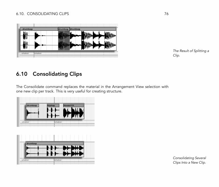
6.10. CONSOLIDATING CLIPS 76
The Result of Splitting aClip.
6.10 Consolidating Clips
The Consolidate command replaces the material in the Arrangement View selection withone new clip per track. This is very useful for creating structure.
Consolidating SeveralClips Into a New Clip.
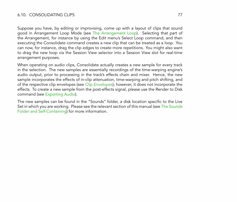
6.10. CONSOLIDATING CLIPS 77
Suppose you have, by editing or improvising, come up with a layout of clips that soundgood in Arrangement Loop Mode (see The Arrangement Loop). Selecting that part ofthe Arrangement, for instance by using the Edit menu's Select Loop command, and thenexecuting the Consolidate command creates a new clip that can be treated as a loop. Youcan now, for instance, drag the clip edges to create more repetitions. You might also wantto drag the new loop via the Session View selector into a Session View slot for real-timearrangement purposes.
When operating on audio clips, Consolidate actually creates a new sample for every trackin the selection. The new samples are essentially recordings of the time-warping engine'saudio output, prior to processing in the track's effects chain and mixer. Hence, the newsample incorporates the effects of in-clip attenuation, time-warping and pitch shifting, andof the respective clip envelopes (see Clip Envelopes); however, it does not incorporate theeffects. To create a new sample from the post-effects signal, please use the Render to Diskcommand (see Exporting Audio).
The new samples can be found in the �Sounds� folder, a disk location speci�c to the LiveSet in which you are working. Please see the relevant section of this manual (see The SoundsFolder and Self-Containing) for more information.

Chapter 7
Session View
In Live's Arrangement View (see Arrangement View), as in all traditional sequencing pro-grams, everything happens along a �xed song timeline. For a number of applications, thisis a limiting paradigm:
� When playing live, or when DJing, the order of pieces, the length of each piece andthe order of parts within each piece is generally not known in advance.
� In the theatre, sound has to react to what happens on stage.
� When working along with a piece of music or a �lm score, it can be more ef�cient andinspirational to start with an improvisation, which is later re�ned into the �nal product.
This is exactly what Live's unique Session View is for.
78

7.1. SESSION VIEW CLIPS 79
7.1 Session View Clips
The Controls for aSession View Clip.
1. Each clip in the Session View has a triangular button at the left edge. Click thebutton with the mouse to �launch� clip playback at any time, or pre-select a clipby clicking on its name, and launch it using the computer's Return key. You canthen move on to the neighboring clips using the arrow keys. Please refer themanual section on clip launch settings (see The Launch Box) for details on howto customize this behavior.
2. Click on a square Clip Stop button to stop a running clip, either in one of thetrack's slots, or in the Track Status �eld below the Session grid.
Clips can be controlled remotely (see MIDI and Key Remote Control) with the computerkeyboard or a MIDI controller. They can even be mapped to MIDI note ranges so that theyplay chromatically.
Clips can be played at any time and in any order. The layout of clips does not predeterminetheir temporal succession; the Session grid offers random access to the clips it contains.
Notice that, even if you stop playback for a Session View clip, the Play button in the ControlBar will remain highlighted, and the Arrangement Position �elds will continue running.These �elds keep a continuous �ow of musical time going, so that you can always know yourposition in song time during a live performance or while recording into the Arrangement(see Recording Sessions into the Arrangement), regardless of what your individual Sessionclips are doing.

7.2. TRACKS AND SCENES 80
You can always return the Arrangement Position �elds to 1.1.1 and stop playback for theentire Live Set by pressing the Control Bar's Stop button twice.
The ArrangementPosition Fields and theStop Button.
7.2 Tracks and Scenes
Each vertical column, or track (see Tracks), can play only one clip at a time. It thereforemakes sense to put a set of clips that are supposed to be played alternatively in the samecolumns: parts of a song, variations of a drum loop, etc.
Resized Session ViewTracks.
For convenient access to more clips at once, you can resize Session View tracks by clickingand dragging at the edges of their title bars. Tracks can be narrowed this way so that onlyClip Launch buttons and essential track controls are visibile.

7.2. TRACKS AND SCENES 81
A Session View Scene.
The horizontal rows are called scenes. The Scene Launch buttons are located in the rightmostcolumn, which represents the Master track (see Return Tracks and the Master Track). Tolaunch every clip in a row simultaneously, click on the associated Scene Launch button. Thiscan be very useful in organizing the live performance of a song with multiple parts.
The scene below a launched scene will automatically be selected as the next to be launchedunless the Select Next Scene on Launch option in the Misc Preferences is set to �Off.�This allows you to trigger scenes from top to bottom without having to select them �rst.Computer keys or a MIDI controller can be used to launch scenes and scroll between them(see Relative Session View Navigation).
Scenes can be renamed using the Edit menu's Rename command. One can quickly renameseveral scenes by executing the Rename command and using the computer's Tab key tomove from one scene to the next.
Each scene can actually store a tempo setting as part of its name, so that it changes theproject tempo upon launch; this is accomplished by selecting the scene and renaming itwith a viable tempo (e.g., �96 BPM�). Any tempo can be used, as long as it is within therange allowed by Live's Tempo control (20�999 BPM).
This Scene Will Changethe Tempo to 96 BPM.

7.3. THE TRACK STATUS FIELDS 82
7.3 The Track Status Fields
You can tell a track's status by looking at the Track Status �eld just above the active track'smixer controls:
A Track Playing aLooping Session Clip...
The pie-chart icon represents a looping Session clip (see Sample Loop/Region and Display).The number to the right of the circle is the loop length in beats, and the number at the leftrepresents how many times the loop has been played since its launch.
... A One-shot SessionClip...
The progress-bar icon represents a one-shot (non-looping) Session clip. The value displaysthe remaining play time in minutes:seconds.
... Monitoring theInput...
A microphone icon appears in an audio track that is set to monitor its input (see Monitoring).A keyboard icon appears in a MIDI track under these same circumstances.
... Playing theArrangement.

7.4. SETTING UP THE SESSION VIEW GRID 83
If the track is playing clips from the Arrangement, a miniature display representing theArrangement clips being played appears.
7.4 Setting Up the Session View Grid
Clips arrive in the Session View by being imported from the File Browsers (see Adding Clipsfrom the Browser) or through recording (see Recording New Clips).
Dropping Multiple ClipsInto the Session View.
If you are dragging multiple clips into the Session View, Live defaults to arrange themvertically, in one track. Hold down Ctrl (PC) / (Mac) prior to dropping them so asto lay the clips out in one scene.
Clips can be moved around the Session grid by drag-and-drop. To move several clipsat once, select them by using the - or Ctrl (PC) / (Mac)-modi�er beforedragging. You can also click into an empty slot and �rubber-band� select from there. Scenescan be reordered by drag-and-drop as well.

7.4. SETTING UP THE SESSION VIEW GRID 84
7.4.1 Select on Launch
By default, clicking a Session View clip's Launch button also selects the clip, since you willtypically want the Clip View to show the newly launched clip. However, some power-usersdon't want the current focus (e.g., a return track's devices) to disappear just because a cliphas been launched, especially when starting a clip in order to try it with the return trackdevice settings. Turn off the Select on Launch option from the Misc Preferences if you preferthe view to remain as is when you launch clips or scenes.
7.4.2 Removing Clip Stop Buttons
Slots Without Clip StopButtons.
You can add and remove Clip Stop buttons from the grid using the Edit menu's Add/RemoveStop Button command. This is useful for pre-con�guring the scene launch behavior: If, forinstance, you don't want scene 3 to affect track 4, remove the scene 3 / track 4 Stop button.
7.4.3 Editing Scenes
There are a number of useful commands in the Edit and Insert menus that apply to scenes:
� Cut Scenes cuts out scenes with selected slots from the Session View, thereby reducingthe total number of scenes. Please note that the Cut Scenes command affects all tracks,not only those containing selected slots.

7.5. RECORDING SESSIONS INTO THE ARRANGEMENT 85
� Paste Scenes works like Paste, but inserts blank scenes before pasting. Live insertsenough scenes to �t the material from the clipboard. The new scenes will be insertedbehind the current selection.
� Duplicate Scenes works like Duplicate, but inserts blank scenes before pasting. Liveinserts enough scenes to �t the material from the clipboard.
� Delete Scenes deletes all scenes with selected slots from the Session View, therebyreducing the total number of scenes. Please note that the Delete Scenes commandaffects all tracks, not only those containing selected slots.
� Insert Scene inserts an empty scene below the current selection.
� Capture and Insert Scene inserts a new scene below the current selection, placescopies of the clips that are currently running in the new scene and launches the newscene immediately with no audible interruption. This command is very helpful whendeveloping materials in the Session View. You can capture an interesting moment asa new scene and move on, changing clip properties and trying clip combinations.
7.5 Recording Sessions into the Arrangement
Your Session View playing can be recorded into the Arrangement, allowing for an improvi-sational approach to composing songs and scores.
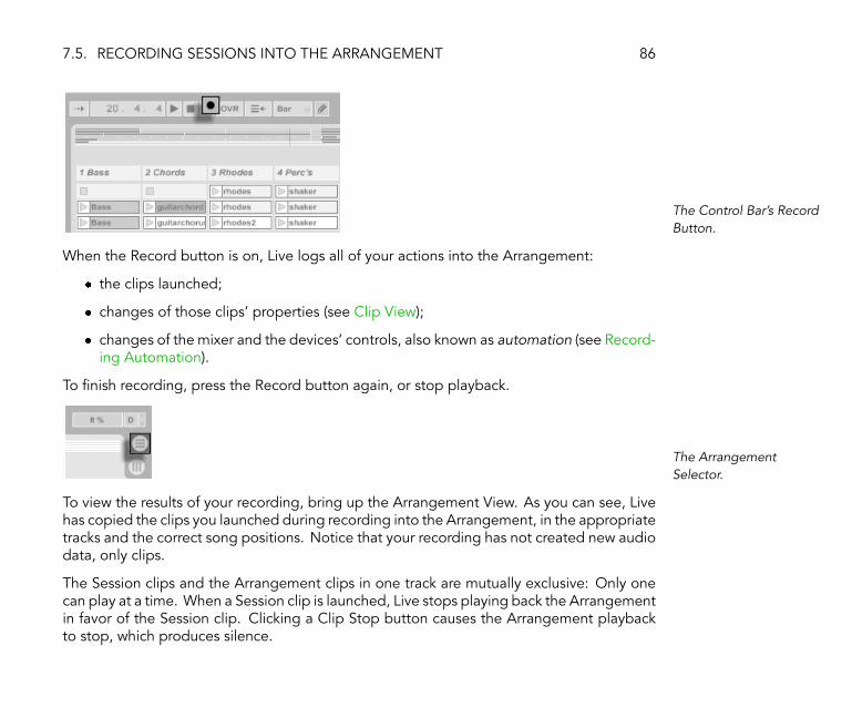
7.5. RECORDING SESSIONS INTO THE ARRANGEMENT 86
The Control Bar's RecordButton.
When the Record button is on, Live logs all of your actions into the Arrangement:
� the clips launched;
� changes of those clips' properties (see Clip View);
� changes of the mixer and the devices' controls, also known as automation (see Record-ing Automation).
To �nish recording, press the Record button again, or stop playback.
The ArrangementSelector.
To view the results of your recording, bring up the Arrangement View. As you can see, Livehas copied the clips you launched during recording into the Arrangement, in the appropriatetracks and the correct song positions. Notice that your recording has not created new audiodata, only clips.
The Session clips and the Arrangement clips in one track are mutually exclusive: Only onecan play at a time. When a Session clip is launched, Live stops playing back the Arrangementin favor of the Session clip. Clicking a Clip Stop button causes the Arrangement playbackto stop, which produces silence.

7.5. RECORDING SESSIONS INTO THE ARRANGEMENT 87
The Back toArrangement Button.
Arrangement playback does not resume until you explicitly tell Live to resume by clickingthe �Back to Arrangement� button, which lights up to remind you that what you hear differsfrom the Arrangement.
The Stop All ClipsButton.
To disable all Arrangement clips simultaneously, click on the Stop All Clips button in theMaster Track Status �eld. The clips in the Arrangement and in the Session View existindependently from one another, which makes it easy to improvise into the Arrangementover and over again until it's right.
Furthermore, you can move clips not only within the Session grid, but also from the SessionView to the Arrangement and vice versa by using Copy and Paste, or by dragging clips over
the or selectors.
When pasting material from the Arrangement into the Session View, Live attempts to pre-serve the temporal structure of the clips by laying them out in a matching top-to-bottomorder. Moving through the scenes from the top down, you can reconstruct the original ar-rangement. This is useful for taking a composed piece of music back to the improvisationalstage.

Chapter 8
Clip View
The Clip View is where clip properties can be set and adjusted.
Clicking the ClipOverview Opens theClip View.
The Clip View is opened by clicking on the Clip Overview or double-clicking a clip in theSession or Arrangement View.
88
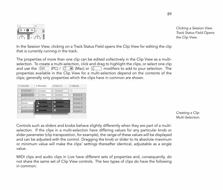
89
Clicking a Session ViewTrack Status Field Opensthe Clip View.
In the Session View, clicking on a Track Status Field opens the Clip View for editing the clipthat is currently running in the track.
The properties of more than one clip can be edited collectively in the Clip View as a multi-selection. To create a multi-selection, click and drag to highlight the clips, or select one clipand use the Ctrl (PC) / (Mac) or modi�ers to add to your selection. Theproperties available in the Clip View for a multi-selection depend on the contents of theclips; generally only properties which the clips have in common are shown.
Creating a ClipMulti-Selection.
Controls such as sliders and knobs behave slightly differently when they are part of a multi-selection. If the clips in a multi-selection have differing values for any particular knob orslider parameter (clip transposition, for example), the range of these values will be displayedand can be adjusted with the control. Dragging the knob or slider to its absolute maximumor minimum value will make the clips' settings thereafter identical, adjustable as a singlevalue.
MIDI clips and audio clips in Live have different sets of properties and, consequently, donot share the same set of Clip View controls. The two types of clips do have the followingin common:
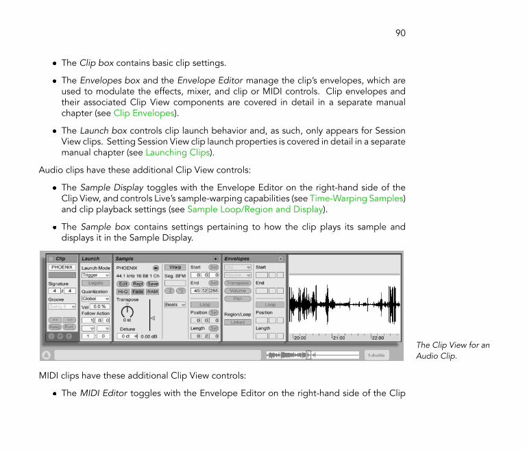
90
� The Clip box contains basic clip settings.
� The Envelopes box and the Envelope Editor manage the clip's envelopes, which areused to modulate the effects, mixer, and clip or MIDI controls. Clip envelopes andtheir associated Clip View components are covered in detail in a separate manualchapter (see Clip Envelopes).
� The Launch box controls clip launch behavior and, as such, only appears for SessionView clips. Setting Session View clip launch properties is covered in detail in a separatemanual chapter (see Launching Clips).
Audio clips have these additional Clip View controls:
� The Sample Display toggles with the Envelope Editor on the right-hand side of theClip View, and controls Live's sample-warping capabilities (see Time-Warping Samples)and clip playback settings (see Sample Loop/Region and Display).
� The Sample box contains settings pertaining to how the clip plays its sample anddisplays it in the Sample Display.
The Clip View for anAudio Clip.
MIDI clips have these additional Clip View controls:
� The MIDI Editor toggles with the Envelope Editor on the right-hand side of the Clip

91
View, and allows editing and creating MIDI notes and velocities (see Editing MIDINotes and Velocities).
� The Notes box contains settings pertaining to how Live plays a MIDI clip and what itdisplays in the MIDI Editor.
The Clip View for a MIDIClip.
To make best use of the screen real estate, you can show or hide the Launch, Envelopes,and Sample or MIDI boxes using the Clip View Box selector in the Clips box. You can alsotoggle between the Sample Display/MIDI Editor and the Envelope Editor by clicking in thetitle bars of the Sample/Notes box and the Envelopes box, respectively.
The Clip View BoxSelector Shows andHides Various Clip ViewComponents.

8.1. THE CLIP BOX 92
8.1 The Clip Box
The Clip Box.
8.1.1 Clip Activator Switch
Using this switch, you can deactivate a clip so that it does not play when launched in theSession View or during Arrangement playback. Clips can also be activated/deactivateddirectly from the Session or Arrangement View with their (PC) / Ctrl (Mac) contextmenus.
8.1.2 Clip Name and Color
The Clip Name �eld allows naming the clip. By default, a clip's name matches the name ofthe �le it references but, in general, the clip name is independent from the �le name.
Renaming an audio clip does not rename the referenced sample �le. To rename a �le, selectit in Live's File Browsers, and then choose the Edit menu's Rename command.
The Clip Color chooser allows choosing a clip color.
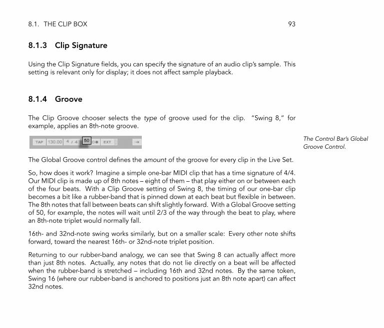
8.1. THE CLIP BOX 93
8.1.3 Clip Signature
Using the Clip Signature �elds, you can specify the signature of an audio clip's sample. Thissetting is relevant only for display; it does not affect sample playback.
8.1.4 Groove
The Clip Groove chooser selects the type of groove used for the clip. �Swing 8,� forexample, applies an 8th-note groove.
The Control Bar's GlobalGroove Control.
The Global Groove control de�nes the amount of the groove for every clip in the Live Set.
So, how does it work? Imagine a simple one-bar MIDI clip that has a time signature of 4/4.Our MIDI clip is made up of 8th notes � eight of them � that play either on or between eachof the four beats. With a Clip Groove setting of Swing 8, the timing of our one-bar clipbecomes a bit like a rubber-band that is pinned down at each beat but �exible in between.The 8th notes that fall between beats can shift slightly forward. With a Global Groove settingof 50, for example, the notes will wait until 2/3 of the way through the beat to play, wherean 8th-note triplet would normally fall.
16th- and 32nd-note swing works similarly, but on a smaller scale: Every other note shiftsforward, toward the nearest 16th- or 32nd-note triplet position.
Returning to our rubber-band analogy, we can see that Swing 8 can actually affect morethan just 8th notes. Actually, any notes that do not lie directly on a beat will be affectedwhen the rubber-band is stretched � including 16th and 32nd notes. By the same token,Swing 16 (where our rubber-band is anchored to positions just an 8th note apart) can affect32nd notes.

8.1. THE CLIP BOX 94
Groove can be applied to both MIDI clips and audio clips. Applying groove to audio clipsdoes require that the Warp switch be activated and a Warp Mode (see Adjusting for GoodStretching Quality) other than Re-Pitch selected. If an audio clip is in Beats Mode, theTransients setting must be greater than or equal to the Clip Groove chooser's swing setting(e.g., with a Transients setting of 1/16, Swing 8 and Swing 16 can be used, but not Swing32).
Because of this feature's dependency on note timing, we recommend that you quantize(see Arranging and Quantizing Notes) MIDI clips prior to applying groove � provided youwant predictable results. For audio clips, any swing contained within the original samplecan be removed by appropriately setting Warp Markers (see Manipulating Grooves) prior toapplying the �arti�cial� swing of the Groove setting.
8.1.5 Clip Offset and Nudging
To jump within a playing clip in increments the size of the global quantization period, youcan use the Nudge buttons in the Clip box.
Using the NudgeButtons to JumpThrough a Clip.
These buttons can also be mapped to keys or MIDI controllers (see MIDI and Key RemoteControl). In MIDI Map mode, a scrub control will appear between the Nudge buttons and

8.1. THE CLIP BOX 95
can be assigned to a rotary encoder wheel for continuous scrubbing.
The Scrub Control inMIDI Map Mode.
With quantization set to values less than one bar, it is easy to offset clip playback from Live'smaster clock by launching clips, using the Nudge buttons or scrubbing within the clip (seePlaying and Scrubbing Clips).
Clip Offset from GlobalTime as Shown in theClip's Display.
When clip play is offset from global time in this manner, a little dot will illuminate in theSample Display or MIDI Editor to display the offset start position.
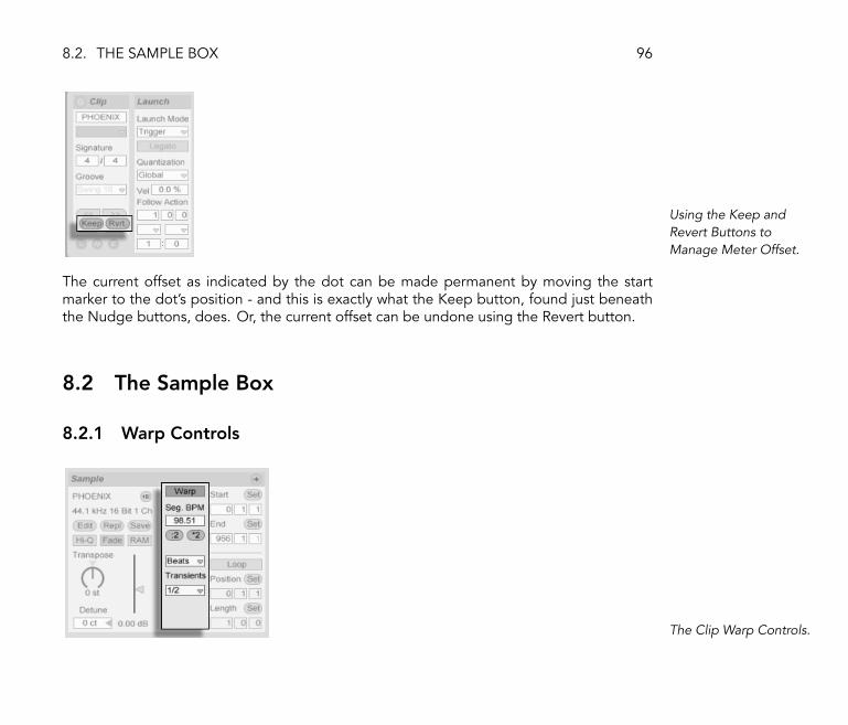
8.2. THE SAMPLE BOX 96
Using the Keep andRevert Buttons toManage Meter Offset.
The current offset as indicated by the dot can be made permanent by moving the startmarker to the dot's position - and this is exactly what the Keep button, found just beneaththe Nudge buttons, does. Or, the current offset can be undone using the Revert button.
8.2 The Sample Box
8.2.1 Warp Controls
The Clip Warp Controls.

8.2. THE SAMPLE BOX 97
When the Warp switch is off, Live plays the sample at its original, �normal� tempo, irrespec-tive of the current Live Set tempo. This is useful for samples that have no inherent rhythmicstructure: percussion hits, atmospheres, sound effects, spoken word and the like. Turnthe Warp switch on to play rhythmically structured samples (such as sample loops, musicrecordings, complete music pieces, etc.) in sync with the current song tempo.
The Control Bar's TempoControl.
To verify this, note that a warped sample's speed follows the tempo as you change theControl Bar's Tempo control.
Live offers a number of controls to adjust the time-warping engine for optimal stretchingquality (see Adjusting for Good Stretching Quality). For accurate warping, Live needs toknow the sample's metrical structure. For properly prepared loops, tempo and durationare calculated automatically; most of the time this is accurate enough that the sample isimmediately ready for use in Live. For other samples, you may have to provide some hints(see Time-Warping Samples).

8.2. THE SAMPLE BOX 98
8.2.2 Sample Loop/Region and Display
Zooming and Scrolling
The Clip Zoom/ScrollArea.
Zooming and scrolling in the Sample Display work much like they do in the ArrangementView (see Navigation). Using the zoom/scroll area in the top half of the waveform, you canclick and drag vertically to smoothly change the zoom level, and horizontally to scroll thedisplay.
The Clip Overview.
The Clip Overview provides additional zoom/scrolling functionality. It always shows thecomplete clip, from start to end. The black rectangular outline represents the part of the
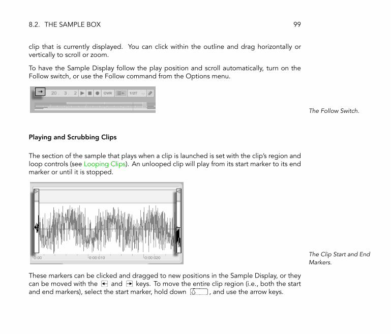
8.2. THE SAMPLE BOX 99
clip that is currently displayed. You can click within the outline and drag horizontally orvertically to scroll or zoom.
To have the Sample Display follow the play position and scroll automatically, turn on theFollow switch, or use the Follow command from the Options menu.
The Follow Switch.
Playing and Scrubbing Clips
The section of the sample that plays when a clip is launched is set with the clip's region andloop controls (see Looping Clips). An unlooped clip will play from its start marker to its endmarker or until it is stopped.
The Clip Start and EndMarkers.
These markers can be clicked and dragged to new positions in the Sample Display, or theycan be moved with the and keys. To move the entire clip region (i.e., both the startand end markers), select the start marker, hold down , and use the arrow keys.

8.2. THE SAMPLE BOX 100
Using Clip Start and EndControls to Change ClipLength.
You can also adjust the clip start and end numerically using the respective value �elds tothe left of the Sample Display. For warped clips, these �elds display values as bars-beats-sixteenths; for unwarped clips, the display is in minutes-seconds-milliseconds. Notice thatyou can use the �Set� buttons here to place the markers during playback. Setting markersthis way is quantized according to global quantization.
Clicking in the scrub area in the lower half of the waveform or above the beat-time ruler willmake clip playback jump to that point.
The Clip Scrub Area.
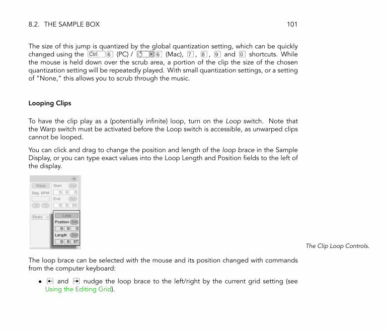
8.2. THE SAMPLE BOX 101
The size of this jump is quantized by the global quantization setting, which can be quicklychanged using the Ctrl 6 (PC) / 6 (Mac), 7 , 8 , 9 and 0 shortcuts. Whilethe mouse is held down over the scrub area, a portion of the clip the size of the chosenquantization setting will be repeatedly played. With small quantization settings, or a settingof �None,� this allows you to scrub through the music.
Looping Clips
To have the clip play as a (potentially in�nite) loop, turn on the Loop switch. Note thatthe Warp switch must be activated before the Loop switch is accessible, as unwarped clipscannot be looped.
You can click and drag to change the position and length of the loop brace in the SampleDisplay, or you can type exact values into the Loop Length and Position �elds to the left ofthe display.
The Clip Loop Controls.
The loop brace can be selected with the mouse and its position changed with commandsfrom the computer keyboard:
� and nudge the loop brace to the left/right by the current grid setting (seeUsing the Editing Grid).

8.2. THE SAMPLE BOX 102
� and shift the loop brace left/right in steps the size of its length.
� Ctrl (PC) / (Mac) shortens or lengthens the loop brace by thecurrent grid setting (see Using the Editing Grid).
� Ctrl (PC) / (Mac) doubles or halves the loop length.
Regardless of the position of the loop brace, clip play upon launch will begin at the positionmarked by the start marker, which means you can set up the clip to run into a loop.
Setting the Clip to RunInto a Loop.
The Loop Length and Position �elds are equipped with Set buttons, which can be used tocreate loops spontaneously during playback:
� Playing the clip and then clicking the Set Loop Position button moves the beginningof loop to the current playback position (rounded to the global quantization setting)and engages the loop. Then, clicking the Set Loop Length button moves the end ofthe loop to the current playback position. This lets you capture the music in a loop onthe �y.
� While the loop is still off, you can click the Set Loop Length button to set the loopto end at the current playback position without changing its preset length. Thissimultaneously activates looping.

8.2. THE SAMPLE BOX 103
The Set buttons, the Loop switch, the loop brace and the start/end markers can all bemapped to MIDI controls (see MIDI and Key Remote Control). You could, for example, usea rotary encoder to move the loop through a sample in increments the size of the chosenquantization interval.
8.2.3 Clip Pitch and Gain
The Clip Pitch and GainControls.
The Transpose control shifts the clip pitch in semitones.
The Detune �eld �ne-tunes the clip in cents (100 cents = one semitone).
The Clip Gain slider, calibrated in dB, changes the clip gain.
8.2.4 Destructive Sample Editing
The Launch SampleEditor Button.

8.2. THE SAMPLE BOX 104
The Launch Sample Editor button opens the sample in a sample editing application, asspeci�ed in the Misc Preferences. To process a sample in an external program, you will haveto stop Live's playback. Upon returning to Live, the edited version of the sample will beplayed back. The current set of Warp Markers is retained only if the sample length remainsthe same as before. Remember that changes to one sample may affect other clips playingthe same sample.
8.2.5 Replacing the Clip's Sample
To replace the sample referenced by the clip with a different sample, drop the new sampledirectly from the File Browser into the Clip View. Clip settings like pitch and volume willbe retained. The Warp Markers will be retained only if the new sample has the exact samelength as the old sample.
Tip: When bringing multitrack audio from another program into Live for remixing, it isconvenient to set Warp Markers for only one of the composite samples and copy the sameset of Warp Markers to the other tracks. This can be easily done provided the individualsamples have the exact same length (which usually is the case if they all have been exportedfrom several tracks in one go): Pick the sample with the clearest rhythmical pronunciation andset the Warp Markers for this sample as described elsewhere (see Time-Warping Samples).Next, make enough copies of this clip to hold all the individual samples, and drop thesamples from the Browser into the clips. The Warp Markers will be retained, because thesamples all have the same length.
The Replace SampleButton.
The Replace Sample button is for replacing a sample throughout the entire Live Set. All clipsthat reference the �old� sample will reference the �new� sample, which is selected using a

8.2. THE SAMPLE BOX 105
�le-chooser dialog. Live retains the clip properties; the Warp Markers (see Time-WarpingSamples) are kept if the new sample has the same or a greater length as the old sampleand discarded otherwise. This function is also useful for locating missing samples that aremarked �of�ine� (see Of�ine and Lost Files).
8.2.6 Saving Default Clip Settings with the Sample
The Save Default ClipButton.
The Save Default Clip button saves the current clip's settings with the sample. Once saved,Live will restore the current clip settings whenever you drop the sample into a Live Set. Thisis especially useful with regards to the Warp Markers, which have to be set correctly forLive to play long �les in sync. Note that you can use the Save button without affecting anyexisting clips; Save just saves default settings for future clips using this sample.
The clip data becomes part of the analysis �le (see Analysis Files (.asd)) that accompaniesthe sample.
Note that storing default clip settings with the sample is different from saving the clip as aLive Clip (see Live Clips), which also saves devices and device settings.

8.2. THE SAMPLE BOX 106
8.2.7 High Quality Interpolation
The High Quality Switch.
If the High Quality switch is on, Live uses an advanced sample-rate conversion algorithm thatprovides better sound quality at the expense of a higher CPU load (see Managing the CPULoad). Samples processed with the Hi-Q algorithm generate less distortion, particularlyat high frequencies, when transposing a sample and/or matching an imported sample'ssampling rate to the system's sampling rate. Note: This feature involves only sample rateconversion, not the time-stretching quality. There are dedicated controls for adjusting thestretching properties (see Adjusting for Good Stretching Quality).
8.2.8 Clip Start and End Fades
The Clip Fade Switch.
The Clip Fade switch, when enabled, applies a short fade to the clip start and end to avoidclicks at the clip edges. The length of the fade is signal-dependent and ranges from 0-4milliseconds.

8.2. THE SAMPLE BOX 107
8.2.9 Clip RAM Mode
The RAM Mode Switch.
If the RAM Mode switch is on, Live is loading the audio referenced by the clip into thecomputer's memory rather than reading it from disk in real time. RAM Mode can help withthese problems:
� Your computer's hard disk is too slow to deliver audio for as many tracks as desiredin real time. For more information on disk-related problems, please refer to therespective section (see Managing the Disk Load).
� You are experiencing audio dropouts when playing clips in Legato Mode (see LegatoMode).
Use RAM Mode with care, as RAM is usually a scarce resource. Your computer is using thehard disk for swapping out RAM contents that have not been used in a while. The moreclips you are running in RAM Mode, the higher the likelihood for them to be swappedout. Live can handle disk overloads more gracefully than swapped-out audio arriving late:Disk overloads result in unwanted mutes, whereas RAM overload results in both mutes andrhythmical �hiccups.�

8.2. THE SAMPLE BOX 108
8.2.10 Reversing Samples
The Reverse Button.
This function creates a new sample by reversing the sample referenced by the currentclip. It then reapplies the old clip's settings (according to some rules that we will explain in amoment), and replaces the original sample with the reversal in the Clip View. The new sampleis stored in your temporary recording folder until you save your Live Set, at which point it ismoved to your Sounds folder (see The Sounds Folder and Self-Containing). The reversedsample has an �R� appended to the end of its name so that it is easily distinguishable fromthe original.
There are a few rules for the reversing process. First, any Warp Markers (see Time-WarpingSamples) will remain �xed to their positions in the sample. This means that a Warp Marker onthe downbeat of the second bar of a clip will end up on the downbeat of the second-to-lastbar after reversal. Clip loop/region settings are similarly �ipped. Second, clip envelopes(see Clip Envelopes) remain �xed to their position in time. Therefore, a mixer volumeenvelope that lowers the volume of the �rst half of a clip will continue to do exactly thatafter reversal.
The reversal process is quite fast (about as fast as copying), but for very long samples it mighttake a little time. When this is the case, the Status Bar in the lower portion of the Live screenwill give you a progress display, and further actions in the program will be temporarily locked(though running clips will continue to play). You can play the reversed clip and perform otheractions in the program as soon as Live begins to draw the new waveform into the SampleDisplay. Once a sample is reversed, a link to the reversed sample will be maintained until theyou quit the program, and reversing the same clip again (or a copy) will be instantaneous.
It is not recommended that you reverse clips in a live performance situation, as a slight glitch

8.3. THE NOTES BOX 109
can sometimes occur while Live reapplies the warp and loop settings.
8.3 The Notes Box
The Notes Box.
8.3.1 Tempo Controls
The �Orig. BPM� �eld displays Live's interpretation of the tempo at which the clip's MIDIwas recorded. When dragging up or down in the Original BPM �eld, or clicking the :2 and*2 buttons, you will see that the notes in the MIDI Editor are correspondingly stretchedor compressed. This is useful for aligning notes that you have recorded without a temporeference, like Live's metronome (see Recording in Sync).
8.3.2 Bank and Program Change
Live can send MIDI bank/program change messages to external devices. According to thesettings in these controls, launching a clip also sends its bank/program change message. If

8.4. CLIP DEFAULTS AND UPDATE RATE 110
you are using Live to send MIDI to your synth, this means that each MIDI clip in your LiveSet can play a different sound on your synth. Live offers messages for 128 banks with 128sub-banks, each of which has 128 programs. Please see the documentation that came withyour synthesizer to determine how many of these messages it can use. If you do not wantyour clip to send program or bank change messages, simply set the bank/program choosersto �None.�
8.3.3 MIDI Loop/Region
These controls manage how the contents of a MIDI clip are played and shown in the MIDIEditor. They work the same way as those for audio clips (see Sample Loop/Region andDisplay).
In the MIDI Editor, the zoom/scroll area is located above the beat-time ruler, the scrub areajust below.
8.4 Clip Defaults and Update Rate
You can change the rate at which Live applies your Clip View settings to a running clip. ClipView changes will be quantized by the rate selected from the Clip Update Rate chooser inthe Misc Preferences.
Certain clip settings, such as Launch Mode and Warp Mode, can be set up as defaults forall new clips. This is done in the the Default Preferences.

Chapter 9
Tempo Control and Warping
Unlike music stored on tape or in a traditional digital audio workstation, the music in Liveremains �elastic� at all times. Live is capable of time-warping samples while streaming themfrom disk so as to synchronize them to the current project tempo. This happens withoutaffecting the pitch, which can be changed independently. Mixing and matching audio fromdifferent origins is therefore extremely easy.
9.1 Tempo
9.1.1 Setting the Tempo
The Control Bar's TempoField.
111

9.1. TEMPO 112
The Control Bar's Tempo �eld allows you to change the playback tempo of your Live Setat any time, in real time. You can even automate the tempo (see Editing the TempoAutomation) to create smooth or sudden tempo changes along the song timeline.
You can have an external sequencer (or drum machine) play along with Live or have Live playalong with the sequencer. The respective settings are made in the MIDI Preferences, andthe EXT switch next to the tempo control is activated to have Live follow an external MIDIclock source. Please refer to the section on synchronization (see Synchronizing via MIDI) fordetails.
9.1.2 Tapping the Tempo
The Tap Button.
You can use Live's Tap Tempo function to set the tempo at any time. As you click the ControlBar's Tap Tempo button once every beat, the tempo of the Live Set will follow your tapping.
The Key Map ModeSwitch.
It's better to assign the Tap button to a computer key than using the mouse. Click on theControl Bar's KEY switch to enter Key Map Mode; then select the Tap button; press the keyyou would like to use for tapping; click the KEY switch again to leave Key Map Mode. Theassignment will take effect immediately. The Tap button can also be assigned to a MIDInote or controller, like a foot switch, in a similar fashion (see MIDI and Key Remote Control).Although Live responds to your tapping immediately, it does apply some degree of inertiato prevent sluggish behavior in the software. The more taps Live receives in a row, the moreprecisely it will be able to conclude the desired tempo.

9.2. TIME-WARPING SAMPLES 113
You can also use tapping to count in: If you are working in a 4:4 signature, it takes four tapsto start song playback at the tapped tempo.
9.2 Time-Warping Samples
Live's ability to play any sample in sync with a chosen tempo is a unique and importantfeature. In addition, you can �warp� the rhythmic �ow of a piece, changing its �feel,� oreven move notes to other meter positions.
Think of a sample as a rubber-band that you want to pin to a (musical time) ruler. In Live,the pins are called Warp Markers. A Warp Marker forces the software to arrive at a speci�cpoint in the sample at a speci�c musical time. You can use any number of Warp Markers tocreate an arbitrary mapping of the piece's inherent rhythm to a musical meter.
Warp Markers are set in the Clip View's Sample Display by double-clicking any of the graygrid markers. They can then be dragged or moved with the arrow keys to different positionsin the clip. Warp Markers are deleted with the keyboard's Backspace or Delete key.
Double-Clicking a GridMarker Creates a WarpMarker.
When working with your sample, you can have Live scroll the Sample Display to followplayback. Use the Control Bar's Follow switch to activate this feature. It also might be

9.2. TIME-WARPING SAMPLES 114
helpful to vertically resize the Sample Display by dragging on the split line between the ClipView and the Session View track area.
The Follow Switch in theControl Bar.
In the following sections, we will look at a couple of applications for time-warping samples.Warping is, of course, an optional feature, and you have several different options for de-activating warping, as described in the respective section in this chapter (see DeactivatingWarping).
Note: For a tip on how to apply the same set of Warp Markers to several multitrack samples,please see here (see Replacing the Clip's Sample).
Of course, your Warp Markers will be saved with the Live Set. In addition, you probablywant to save them with the sample, so that they are reconstructed the next time you dragthe �le into Live. To do this, click the Clip View's Save button (see Analysis Files (.asd)).
9.2.1 Syncing Straight Loops
When you import a sample that represents a well-cut musical loop of 1,2,4 or 8 bars inlength, Live usually makes the correct assumptions to play the loop in sync with the chosentempo. It places two Warp Markers, one at the sample's beginning and one at the end.

9.2. TIME-WARPING SAMPLES 115
A One-Bar Loop as ItAppears in the ClipView, by Default.
The �Orig. BPM� �eld displays Live's guess of the loop's tempo; if you happen to know thetempo of the loop, you can type it in here. Sometimes Live's guess of the original tempois wrong by half or double. If so, correct this by clicking on the buttons labeled *2 and:2, respectively. The sample plays at double speed when you press :2 because you arechanging Live's interpretation of the sample's tempo, which serves as a point of referencefor determining the required time-stretch factor.
9.2.2 Syncing Uncut Loops
When importing a loop that has not been edited into a well-cut loop, Live will play it out ofsync. Suppose there is a portion of silence at the sample beginning, prior to the �rst beat.You can easily correct this by moving the Warp Marker labeled with a �1� to the �rst beat'sonset. Likewise, you can eliminate silence after the actual loop end by moving the WarpMarker at the sample's right edge.

9.2. TIME-WARPING SAMPLES 116
Setting the WarpMarkers for a Badly CutLoop.
9.2.3 Syncing Odd-Length Loops
If you import a sample that contains a seven-bar loop, Live initially assumes the loop is eightbars long (or four, depending on its length) and plays it out of sync. For correct playback,the last marker needs to show a eight, not a nine. To achieve this do the following:
1. Double-click on the last Warp Marker to delete it.
2. Double-click on the eight to create a new Warp Marker.
3. Drag the new Warp Marker to the sample end.
If Live's initial guess had been a four-bar loop, the eight would not have been accessible. Inthat case, you could initially drag the Warp Marker at the end toward the left until the eightbecame visible.
Theoretically this should have done the job for our seven-bar loop. Practically, though, it isvery likely that moving the markers led to a change of the loop start and end points. Thisis because the loop is tied to the meter grid and therefore moves with the Warp Markers,which de�ne the meter grid. Live makes sure the loop �ts in the sample, and therefore hasto change its length if required by a Warp Marker change.
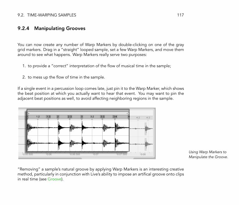
9.2. TIME-WARPING SAMPLES 117
9.2.4 Manipulating Grooves
You can now create any number of Warp Markers by double-clicking on one of the graygrid markers. Drag in a �straight� looped sample, set a few Warp Markers, and move themaround to see what happens. Warp Markers really serve two purposes:
1. to provide a �correct� interpretation of the �ow of musical time in the sample;
2. to mess up the �ow of time in the sample.
If a single event in a percussion loop comes late, just pin it to the Warp Marker, which showsthe beat position at which you actually want to hear that event. You may want to pin theadjacent beat positions as well, to avoid affecting neighboring regions in the sample.
Using Warp Markers toManipulate the Groove.
�Removing� a sample's natural groove by applying Warp Markers is an interesting creativemethod, particularly in conjunction with Live's ability to impose an arti�cal groove onto clipsin real time (see Groove).

9.2. TIME-WARPING SAMPLES 118
9.2.5 Syncing Longer Pieces
Live's Auto-Warp algorithm makes longer samples and entire songs readily available forintegration into your project. You can use the Browser (see Adding Clips from the Browser)to import long samples or MP3, Ogg Vorbis, Ogg FLAC and FLAC �les.
When you drag a �le into Live that is too long to justify the assumption that it is a loop or aone-shot, Live will auto-warp the clip by default (though this can be changed in the DefaultPreferences (see Deactivating Warping)).
Note that, for the auto-warp mechanism to work, �les which are being imported into theprogram for the �rst time will need to undergo a �rst-time analysis process (see AnalysisFiles (.asd)) and will not be immediately available for playing or editing. As explained in thesection in this manual on analysis �les, analysis can be batch-processed with the (PC) /
Ctrl (Mac) context menu's Analyze Audio command. Once analysis is �nished, you canview the results of Auto-Warp's assumptions about the �le.
Auto-Warp's Results inthe Clip View.
As long as Auto-Warp made the correct set of informed guesses, the clip will be ready toplay in perfect sync with Live's project tempo. However, if Auto-Warp does not quite dowhat you want, you can control its results. The remainder of this section will focus on variousways of guiding Live's auto-warping. Remember that the metronome in the Control Bar will

9.2. TIME-WARPING SAMPLES 119
probably come in handy as you warp longer pieces.
The Metronome Switch.
It might happen that Auto-Warp guesses the tempo correctly but gets the downbeat wrong.To remedy this, you can do the following:
� Zoom in and drag the 1.1.1 marker to the desired position;
� Use the start marker's (PC) / Ctrl (Mac) context menu to select the Set 1.1.1Here command.
Using the Context Menuto Direct Auto-Warp.
Directing Auto-Warp is also relatively simple when you have imported a perfectly cut loop.You can tell Auto-Warp to work accordingly using the Warp As ...-Bar Loop command. Livewill propose a loop length that makes the most sense given the current project tempo.Decreasing the project tempo can, for instance, lead Live to assume the loop is 8 bars at 90BPM instead of 16 bars at 180 BPM.
Sometimes more detailed control of Auto-Warp is necessary. The best way to go aboutwarping a clip that requires more detailed attention is in sections, working gradually from

9.2. TIME-WARPING SAMPLES 120
left to right. You can set a Warp Marker by double-clicking one of the gray grid markers tothe right of each correctly warped section, �pinning� it into place. The shortcuts for workingwith the clip loop brace and start/end markers (see Sample Loop/Region and Display) canspeed up this process considerably. You might also �nd it helpful to select multiple WarpMarkers for moving by appending to your selected Warp Marker with the or Ctrl
(PC) / (Mac) modi�ers held down.
The four �Warp From Here� commands provide various ways of resetting Warp Markers tothe right of the selected grid or Warp Marker, leaving Warp Markers to the left untouched.These commands are also available from the start marker.
� Warp From Here runs the Auto-Warp algorithm on the material to the right of theselected marker.
� Warp From Here (Start At ...) directs Auto-Warp to use the project tempo as a startingpoint for tempo tracking. The strategy here is as follows:
1. Deactivate the Warp switch for the clip and play it (or the section in question)unwarped;
2. Use the Control Bar's Tap Tempo button to tap along and set the projecttempo to match that of the clip;
3. Turn warping on again and use the Warp From Here (Start At ...) commandto tell Auto-Warp to use your tapped tempo and warp from there.
� Warp From Here (Straight) tells Auto-Warp that this is a clip with no tempo variations,i.e., an electronically produced piece. Auto-Warp will therefore set a single WarpMarker according to its guess about the original �le's tempo.
� Warp ... BPM From Here will also set only a single Warp Marker, but in this case, Auto-Warp is forced to interpret the piece as exactly matching the project tempo. This isuseful in cases when you happen to know the exact BPM value of an electronicallyproduced piece and can type it into the Control Bar before warping.

9.3. ADJUSTING FOR GOOD STRETCHING QUALITY 121
Of course, your Warp Markers will be saved with the Live Set. In addition, you probablywant to save them with the sample, so that they are reconstructed the next time you dragthe �le into Live. To do this, click the Clip View's Save button (see Analysis Files (.asd)).
Note that, if a sample has a saved set of Warp Markers (see Saving Default Clip Settingswith the Sample), Auto-Warp will have no effect. When this is the case, you can use any ofthe (PC) / Ctrl (Mac) context menu commands described in this section to initiateauto-warping.
9.3 Adjusting for Good Stretching Quality
Live offers a number of time-stretching methods to accommodate all sorts of audio material.The time-stretching method, and additional controls for each method, are set up in the ClipView's �Warp� box.
The Warp Modes are different varieties of granular resynthesis techniques. Granular resyn-thesis achieves time compression and expansion by repeating and skipping over parts ofthe sample (the �grains�). The Warp Modes differ by the selection of grains, as well as bythe details of overlapping and crossfading between grains.
Let's investigate which Warp Modes work best for different types of signals and how toadjust the warping controls for �clean� stretching. It's also fun to �misuse� these controlsto achieve interesting artifacts instead of correct stretching.
9.3.1 Beats Mode
Beats Mode works best for material where rhythm is predominate (e.g., drum loops as wellas most pieces of electronic dance music). The granulation process is optimized to preservetransients (attacks, note onsets) in the audio material.

9.3. ADJUSTING FOR GOOD STRETCHING QUALITY 122
Use the Transients control to guide Live's assumptions about where to �nd transients inthe waveform. If there is no rhythmical activity at odd 16th notes, choose 8th, etc. Forsome interesting rhythmic artifacts, choose large transient values in conjunction with pitchtransposition.
9.3.2 Tones Mode
Tones Mode serves well for stretching material with a more or less clear pitch structure, suchas vocals, monophonic instruments and basslines.
Grain Size provides rough control over the average grain size used. The actual grain sizeis determined in a signal-dependent way. For signals with a clear sense of pitch contour, asmall grain size works best. Larger grain sizes help avoid artifacts that can occur when thepitch contour is unclear, but the tradeoff can be audible repetitions.
9.3.3 Texture Mode
Texture Mode works well for sound textures with an ambiguous pitch contour (e.g., poly-phonic orchestral music, all sorts of noise, atmospheric pads, etc.). It also offers rich potentialfor manipulating all kinds of sounds in a creative way.
The Grain Size control determines the grain size used; unlike in Tones Mode, this is a settingthat Live will use unaltered, without factoring in the signal's characteristics.
Fluctuation introduces randomness into the process. Larger values give more randomness.
9.3.4 Re-Pitch Mode
In Re-Pitch Mode, Live doesn't really time-stretch or compress the music; instead, it adjuststhe playback rate to create the desired amount of stretching. In other words, to speed

9.4. DEACTIVATING WARPING 123
up playback by a factor of 2, it's transposed up an octave. This is like the �DJ stretchingmethod� of using variable-speed turntables to sync two records, or what happens to samplesin samplers when they're transposed.
The Transpose and Detune controls have no effect in Re-Pitch Mode.
9.3.5 Complex Mode
Complex Mode is a warping method speci�cally designed to accommodate compositesignals that combine the characteristics covered by other Warp Modes; it works well forwarping entire songs, which usually contain beats, tones and textures.
Complex Mode is a rather CPU-intensive function, using approximately ten times the CPUresources required by the other Warp Modes. As such, you may want to freeze tracks (seeTrack Freeze) where Complex Mode is in use or record (see Recording New Clips) the resultsas a new clip to use as a substitute.
9.4 Deactivating Warping
You can direct Live's assumptions about new samples using the Default Preferences. If theAuto-Warp Long Samples preference is on, Live assumes that long samples contain musicthat should be played in sync with the project tempo. If you would rather have Live defaultto playing long samples as they are, disengage this preference.
Regardless of how Live interprets new samples by default, you can always override thesedecisions on a per-clip basis by toggling the Clip View's Warp switch.
Chapter 10
Editing MIDI Notes and Velocities
A MIDI clip in Live contains notes and controller data for playing a MIDI instrument. Thisinstrument can be a virtual instrument in a MIDI track's device chain (see Working withInstruments and Effects) or an external synth fed via the track's output routing (see Routingand I/O). The MIDI clip (see MIDI Clips and MIDI Files) provides the device with a musicalscore to play, specifying note pitch, length, position and dynamics (referred to as velocity inthe MIDI lexicon). MIDI is composed and edited in Live's MIDI Editor.
10.1 Creating an Empty MIDI Clip
MIDI clips are created
� by means of recording (see Recording New Clips);
� or by double-clicking an empty Session slot in a MIDI track;
124

10.2. THE MIDI EDITOR 125
� or by selecting an empty Session slot in a MIDI track and choosing the Insert menu'sInsert MIDI Clip command;
� or, in the Arrangement View, by selecting a timespan in a MIDI track and choosing theInsert menu's Insert MIDI Clip command.
10.2 The MIDI Editor
To bring up the MIDI Editor, double-click a MIDI clip to open the Clip View. You can use theClip View Box selector to make sure the Notes box (see The Notes Box) is showing, thenclick in the title bar of the Notes box to bring up the MIDI Editor on the right-hand side ofthe screen.
The MIDI Editor.
The MIDI Editor is comprised of two editing windows: the upper Note Editor and the lowerVelocity Editor. You can resize the Velocity Editor by dragging on the split line that runsbetween it and the Note Editor. You can also show and hide the Velocity Editor using thetriangular button on the left-hand side of the split line.

10.2. THE MIDI EDITOR 126
The Control Bar's DrawMode Switch.
Switch to Draw Mode by activating the Control Bar's Draw Mode switch. You can now drawMIDI notes into the Note Editor with the mouse. Deactivating Draw Mode allows notes tobe selected and moved around by clicking and dragging, either vertically to change theirtransposition, or horizontally to change their position in time.
Previewing MIDI Notes.
Provided your MIDI track's device chain contains an instrument (see Working with Instrumentsand Effects), activating the Preview switch in the MIDI Editor allows you to hear notes as youselect and move them.
Note velocity is adjusted in the Velocity Editor, by clicking and dragging on the associatedmarkers. You can also use Draw Mode in the Velocity Editor: It will draw identical velocitiesfor all notes within a grid �tile.�
After drawing a few notes and moving them around, you will probably want to know how toget around in the Note Editor. So, before we get into detailed editing information, we will�rst explain MIDI Editor navigation.

10.3. MIDI EDITOR NAVIGATION AND TRANSPORT 127
10.3 MIDI Editor Navigation and Transport
Note Scale Position IsShown Vertically andBeat-Time Horizontally.
The MIDI Editor has both vertical and horizontal navigation. Along the horizontal axis liesa time ruler, which shows note position along a musical timeline. The vertical axis containsboth the note ruler, displaying octaves C0�C10, and a representation of a piano keyboard(the piano roll). Note that if the Preview switch at the top of the piano roll is activated, youcan listen to the results of your piano roll playing.

10.3. MIDI EDITOR NAVIGATION AND TRANSPORT 128
12 3 5 6
MIDI Editor Navigation.
1. To smoothly change the time-zoom level, click and drag vertically in the timeruler. Drag horizontally in the time ruler to scroll from left to right.
2. Click and drag vertically in the note ruler to change which octaves are shown,or drag horizontally to change the vertical zoom size of MIDI notes and thekeyboard.
3. Click and drag over one or more notes to de�ne a selection. Then, double-clickon the note ruler to automatically zoom in on your selection. If no notes areselected, double-clicking the note ruler will zoom in on the area from the lowestto the highest note in the clip.
4. To zoom in and out around the current selection, use the computer keyboard's+ and - keys.
5. The Clip Overview just beneath the MIDI Editor can also be used for navigation.It always shows the complete contents of the selected MIDI clip. The blackrectangular outline represents the part of the clip that is currently displayed inthe Editor above. To scroll, click within the outline and drag left or right; to zoom

10.3. MIDI EDITOR NAVIGATION AND TRANSPORT 129
in and out, drag up and down.
6. Change the length of what is shown in the Editor by dragging the left or rightedges of the outline in the Clip Overview.
7. To quickly change what is shown in the Editor, click on a section that you wantto examine in the Clip Overview, then drag downwards to zoom in, or scroll bydragging left and right.
8. The Page Up and Page Down keys on your computer keyboard scroll the NoteEditor vertically. The Ctrl (PC) / (Mac) modi�er will change this tohorizontal scrolling.
The Control Bar's FollowSwitch.
The area displayed in the Note Editor can be set to scroll with playback using the Followswitch from the Control Bar.
The MIDI Clip ScrubArea.
You can click in the scrub area just below the beat-time ruler to start playback from thatpoint, rounded by the global quantization setting. Learning about the loop/region controls(see MIDI Loop/Region) and associated shortcuts can also be helpful in getting around inthe MIDI Editor and playing selections quickly and easily.
As you work with MIDI, you may �nd yourself needing extra screen space. You can click anddrag vertically on the window split between the Session or Arrangement View and the Clip

10.4. EDITING MIDI 130
View to enlarge the MIDI Editor.
Enlarge the MIDI Editorby Dragging theWindow Split BetweenSession and Clip Views.
10.4 Editing MIDI
10.4.1 Non-Destructive Editing
You can always return your MIDI clip to its previous state by using the Edit menu's Undocommand. Furthermore, if the MIDI clip being edited originated in a MIDI �le on your harddrive, none of your editing will alter the original MIDI �le, as Live incorporates its contentsinto your Live Set when importing.
10.4.2 Folding and Looping
An important feature of the MIDI Editor is the Fold button, located in the upper left corner.Activating this button will immediately hide all rows, or key tracks, that do not containMIDI notes. This is very useful when working with percussion kits, for example, which areoftentimes mapped out along a keyboard in sections corresponding to percussion type
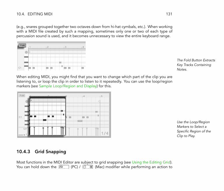
10.4. EDITING MIDI 131
(e.g., snares grouped together two octaves down from hi-hat cymbals, etc.). When workingwith a MIDI �le created by such a mapping, sometimes only one or two of each type ofpercussion sound is used, and it becomes unnecessary to view the entire keyboard range.
The Fold Button ExtractsKey Tracks ContainingNotes.
When editing MIDI, you might �nd that you want to change which part of the clip you arelistening to, or loop the clip in order to listen to it repeatedly. You can use the loop/regionmarkers (see Sample Loop/Region and Display) for this.
Use the Loop/RegionMarkers to Select aSpeci�c Region of theClip to Play.
10.4.3 Grid Snapping
Most functions in the MIDI Editor are subject to grid snapping (see Using the Editing Grid).You can hold down the Alt (PC) / (Mac) modi�er while performing an action to

10.4. EDITING MIDI 132
bypass grid snapping.
Note movements will also snap to an �offset,� which is based on the original placement ofthe note relative to the grid. This is useful for preserving a groove or loose playing style thatyou do not necessarily want to �set straight.�
10.4.4 Arranging and Quantizing Notes
As we have seen, notes in the MIDI Editor can be moved both horizontally (changing theirposition in time) and vertically (changing their transposition). They can be moved either byclicking and dragging, or with the arrow keys on your computer keyboard; in either case,they are subject to grid and offset snapping. If you are playing the clip while you movenotes, you can listen to them play in their new assignments as you drag them, withoutwaiting until you have released the mouse button.
Multiple notes can be selected and moved in unison: �Rubber-band� select more than onenote with one mouse motion by clicking in empty space, then dragging diagonally upwardor downward to enclose the notes in the dotted line that appears.
You can use the modi�er to click and add individual notes or additional �rubber-band� selections to your current selection. You can also remove a single note from yourselection by holding down and clicking on it. Holding and clicking on thepiano roll selects all notes in a single key track.
There are two options for quantizing MIDI notes in Live. As previously mentioned (see GridSnapping), you can move notes so that they snap to the visible grid lines. Alternatively, youcan select a note or notes and choose �Quantize� from the Edit menu, or use the Ctrl U
(PC) / U (Mac) hotkey. This brings up a dialog box with several quantization options.

10.4. EDITING MIDI 133
Quantizing MIDI Notes.
Using the options presented here, you can select a meter value for quantization and seteither the note start or end (or both) to be quantized. Quantizing the note end will stretchthe note so that it ends at the chosen meter subdivision. You can also quantize notes withoutgiving them that �quantized� feel using the Amount control, which will move notes only bya percentage of the set quantization value.
10.4.5 Creating and Editing Notes
Selecting a note (or notes) makes it subject to commands from the Edit menu, such as Copyand Paste. You can use the Ctrl (PC) / Alt (Mac) modi�er to click and drag a copy ofa note to a new location.
The Edit menu's Select Loop command selects all notes that begin within the loop brace.The Select Loop command can also be executed without the menu by simply clicking theloop brace. This command can speed up editing when coupled with the loop brace'sshortcuts (see Sample Loop/Region and Display). Let's say you have arranged a nice 1-barloop in the Note editor, and you want to duplicate it a couple of times. You can click theloop brace to select the notes that begin within the loop, execute the Edit menu's Copy
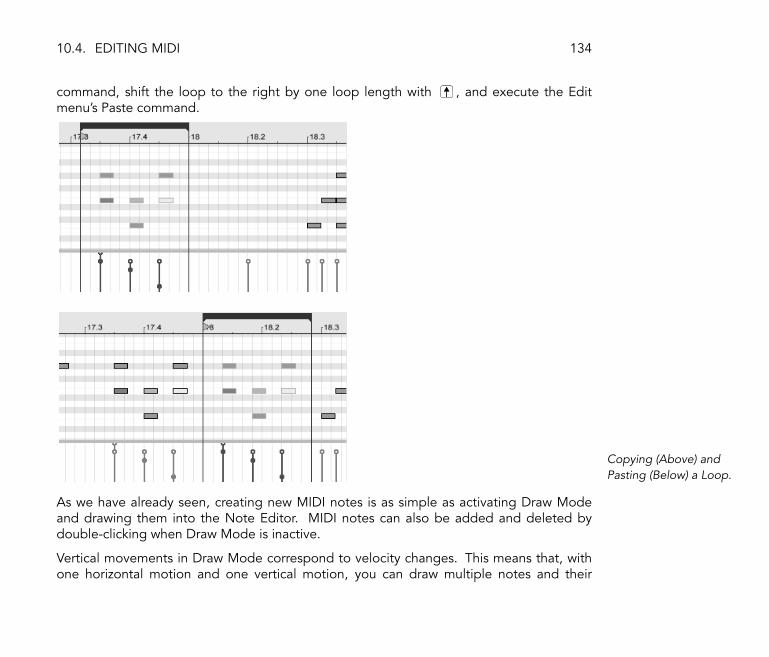
10.4. EDITING MIDI 134
command, shift the loop to the right by one loop length with , and execute the Editmenu's Paste command.
Copying (Above) andPasting (Below) a Loop.
As we have already seen, creating new MIDI notes is as simple as activating Draw Modeand drawing them into the Note Editor. MIDI notes can also be added and deleted bydouble-clicking when Draw Mode is inactive.
Vertical movements in Draw Mode correspond to velocity changes. This means that, withone horizontal motion and one vertical motion, you can draw multiple notes and their

10.4. EDITING MIDI 135
velocities without releasing the mouse button. If you change velocity with this verticalmovement, Live will remember the change and use your new velocity on any notes that youdraw afterward.
You may sometimes, by dragging or by drawing, place a new note on top of one that alreadyexists. If the new note overlaps with the beginning of the original note, the original note willvanish. The original note is invisible, but still exists, and will reappear intact if the new noteis moved away again. If the new note overlaps with the �tail� of the original, the originalnote's length will change so that it lasts just until the new note's beginning. This, too, isnot an irreversible action, and the old note length will be restored if the new clip is againmoved.
10.4.6 Changing Note Length
Clicking and dragging on a note's left or right edges changes its length. Note length canonly be changed when Draw Mode is inactive, and will be quantized unless the Alt (PC)/ (Mac) modi�er is held down while dragging.
Changing Note Length.
Tip: To set a group of notes to the same length, select them all, grab the end of the longestone, drag them all down to zero length and then extend them.

10.4. EDITING MIDI 136
10.4.7 Editing Velocities
To change velocity for a MIDI note, click and drag on the associated marker in the VelocityEditor. (To help you locate the velocity marker belonging to a MIDI note that may be stackedvertically with others, Live highlights the velocity marker for whichever note your mouse ishovering over.) Velocity changes will be shown numerically in a small display in the timeruler.
Changing Note Velocity.
As in the Note Editor, you can select multiple velocity markers to change by clicking withthe modi�er held down.
Tip: To set a group of notes so that they all have the same velocity, select their markers inthe Velocity Editor, drag them up to maximum velocity and then decrease velocity to thedesired value.
As we saw earlier, Draw Mode allows drawing identical velocities for all notes within a gridtile. Velocity drawing can be limited to only those notes that are currently selected if the
modi�er is held. To draw markers individually (as you would want to with a crescendo,for instance) deactivate grid snapping with the Ctrl 4 (PC) / 4 (Mac) shortcut, orsimply hold down the Alt (PC) / (Mac) modi�er.

10.4. EDITING MIDI 137
Drawing IdenticalVelocities (Above) and aCrescendo (Below).
Tip: To draw a velocity ramp with notes that are all in the same key track, press andclick on the piano roll to select all notes within the desired key track, make sure Draw Mode

10.4. EDITING MIDI 138
is activated and draw the ramp into the Velocity Editor while holding the modi�er,so that you affect only the selected notes.
Notes in the Note Editor display their velocity in their coloring � light notes play softly,and vice versa. To change the velocity of notes without the Velocity Editor open, click anyselected note and drag vertically while pressing the the Alt (PC) / (Mac) modi�er.
10.4.8 Deactivating Notes
To deactivate, or mute, a note (or notes) in the MIDI Editor, select it and (PC) / Ctrl
(Mac) to access the context menu. The Deactivate Note(s) command will mute the note,making it appear gray in the display. To reactivate notes, use the context menu's ActivateNote(s) command.
Chapter 11
Launching Clips
The Live Session View is set apart by the fact that it gives you, the musician, an spontaneousenvironment that encourages performance and improvisation. An important part of howyou take advantage of the Session View lies within how you con�gure your various SessionView clips. This chapter explains the group of settings used to de�ne how each SessionView clip behaves when triggered, or �launched.�
11.1 The Launch Box
Remember that clips in the Session View are launched by their Clip Launch buttons (seeSession View Clips) or remote control (see MIDI and Key Remote Control). Clip launchsettings are made in the Launch box. The Launch box only applies to Session View clips,as Arrangement View clips are not launched but played according to their positions in theArrangement.
139

11.2. LAUNCH MODES 140
To view the Launch box, open the Clip View (see Clip View) of a Session View clip bydouble-clicking the clip, then activating the leftmost Clip View Box selector panel.
Use the Clip View BoxSelector to Bring up theLaunch Box.
Note that you can edit the launch settings of more than one clip at the same time by �rstselecting the clips and then opening the Clip View.
11.2 Launch Modes
The Clip Launch ModeChooser.
The Launch Mode chooser offers a number of options for how clips behave with respect tomouse clicks, computer keyboard actions or MIDI notes (see MIDI and Key Remote Control):
� Trigger: down starts the clip; up is ignored.
� Gate: down starts the clip; up stops the clip.
� Toggle: down starts the clip; up is ignored. The clip will stop on the next down.

11.3. CLIP-LEVEL QUANTIZATION 141
� Repeat: As long as the mouse switch/key is held, the clip is triggered repeatedly atthe clip quantization rate.
11.3 Clip-Level Quantization
The Clip QuantizationChooser.
The Clip Quantization chooser lets you adjust an onset timing correction for clip triggering.To disable clip quantization, choose �None.�
To use the Control Bar's Global Quantization setting, choose �Global.� Global quantizationcan be quickly changed using the Ctrl 6 (PC) / 6 (Mac), 7 , 8 , 9 and 0
shortcuts.
Note that any setting other than �Global� or �None� will quantize the clip's launch when itis triggered by Follow Actions (see Follow Actions).

11.4. VELOCITY 142
11.4 Velocity
The Velocity AmountField.
The Velocity Amount control allows you to adjust the effect of MIDI note velocity on theclip's volume: If set to zero, there is no in�uence; at 100 percent, the softest notes play theclip silently. For more on playing clips via MIDI, see the respective section (see MIDI RemoteControl).
11.5 Legato Mode
The Legato ModeSwitch.
Suppose you have gathered, in one track, a number of looping clips, and you now want totoggle among them without losing the sync. For this you could use a large quantizationsetting (one bar or greater), however, this might limit your musical expression.
Another option, which works even with quantization turned off, is to engage Legato Modefor the respective clips. When a clip in Legato Mode is launched, it takes over the play
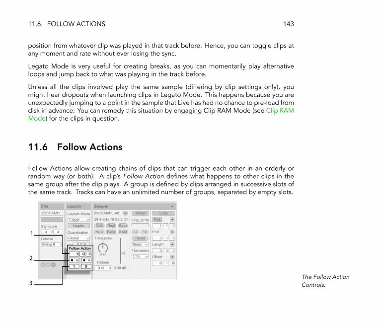
11.6. FOLLOW ACTIONS 143
position from whatever clip was played in that track before. Hence, you can toggle clips atany moment and rate without ever losing the sync.
Legato Mode is very useful for creating breaks, as you can momentarily play alternativeloops and jump back to what was playing in the track before.
Unless all the clips involved play the same sample (differing by clip settings only), youmight hear dropouts when launching clips in Legato Mode. This happens because you areunexpectedly jumping to a point in the sample that Live has had no chance to pre-load fromdisk in advance. You can remedy this situation by engaging Clip RAM Mode (see Clip RAMMode) for the clips in question.
11.6 Follow Actions
Follow Actions allow creating chains of clips that can trigger each other in an orderly orrandom way (or both). A clip's Follow Action de�nes what happens to other clips in thesame group after the clip plays. A group is de�ned by clips arranged in successive slots ofthe same track. Tracks can have an unlimited number of groups, separated by empty slots.
3
1
2
The Follow ActionControls.
11.6. FOLLOW ACTIONS 144
1. The Follow Action Time control de�nes when the Follow Action takes place inbars-beats-sixteenths from the point in the clip where play starts. The default forthis setting is one bar.
2. The Follow Action choosers allow selecting two different Follow Actions, A andB.
3. The Chance A and Chance B controls set the likelihood of each of the twoFollow Actions occurring. If a clip has Chance A set to 1 and Chance B set to0, Follow Action A will occur every time the clip is launched. As we can seefrom this example, a Chance setting of 0 means that an action will never happen.Changing Chance B to 10 in this scenario makes Follow Action A occur muchless often � approximately once out of every ten clip launches.
There are eight Follow Actions available:
�Play Clip Again� restarts the clip.
�Play Next Clip� triggers the next clip down in the group. If a clip with this setting is lastin a group, this Follow Action triggers the �rst clip.
�Play Previous Clip� triggers the previous clip (the one above the current one).
�Play Any Clip� plays any clip in the group.
�Stop� simply stops the clip after it has played for the chosen Follow Action Time. Notethat this overrides clip loop/region settings.
�Play First Clip� launches the �rst (top) clip in a group.
�Play Last Clip� launches the last (bottom) clip in a group.
There is also the possibility to choose no Follow Action by leaving the chooser blank.
Note that a Follow Action happens exactly after the duration that is speci�ed by the FollowAction Time controls unless clip quantization is set to a value other than �None� or �Global.�Follow Actions circumvent global quantization but not clip quantization.

11.6. FOLLOW ACTIONS 145
So, why do you need these things? Music is repetition and change. Music based on loopsor short melodic fragments has a tendency to sound static. Follow Actions allow you tocreate structures that will repeat but can also be surprising. Remember that you can alwaysrecord (see Recording New Clips) the results of your experiments, so this can provide a goodsource for new material.
In the following sections we will look at some practical examples and ideas for FollowActions.
11.6.1 Looping Parts of a Clip
Let's say that you want to play a longer clip, but then you want only the last eight bars toloop. You can set this up using Follow Actions:
1. Drag the clip into the Arrangement View and make sure that the Clip View's Loopswitch is not activated. Use the Edit menu's Split command (see Splitting Clips)to split the clip between the non-looping and looping parts.
2. Click and drag the resulting two clips into the Session View by letting the mousecursor hover over the Session View selector. Drop the two clips into a track. Theynow form a Follow Action group.
2
3 Creating a Group Withthe Two Clips.

11.6. FOLLOW ACTIONS 146
3. Set up Follow Actions for the �rst clip. You will want to make Follow Action Timeequal to the clip's length. Set the Follow Action A chooser to �Play Next Clip,�with a Chance setting of 1, leaving Follow Action B alone. Now this clip is setup to advance to the looping clip after it plays.
4. Activate the Loop switch for the second clip.
The �rst clip will now proceed to the second after it has played in its entirety; the secondclip will simply play in a loop until it is stopped.
11.6.2 Creating Cycles
One of the most obvious possibilities that Follow Actions open up is using a group ofsamples to form a musical cycle. If we organize several clips as a group and use the �PlayNext Clip� Follow Action with each clip, they will play one after the other ad in�nitum, oruntil we tell them to stop.
Cycles can be peppered with occasional rearrangements through the addition of otherFollow Actions, such as �Play Any Clip,� with smaller relative Chance settings.
11.6.3 Temporarily Looping Clips
There are some interesting applications of Follow Actions when it comes to creating tem-porary musical loops.
The default setting for Follow Action is actually a 1:0 chance that �Nothing� happens afterthe Follow Action Time, which means that there is effectively no Follow Action. But now,imagine a group consisting of one single clip. Follow Action A is set to �Play Clip Again,�with a Chance of 8. Follow Action B is set to �None,� with a Chance of 1. The clip usesa long sample, and Follow Time is set to one bar. Clicking on the clip will play the �rstbar, after which it will be very likely that it will play the �rst bar again. However, after a few

11.6. FOLLOW ACTIONS 147
repetitions, it will eventually come to Action B � �Nothing� � and continue playing the restof the sample.
Or, a clip can be played from its start to a speci�c point, when its Follow Action tells it to�Play Next Clip.� The same �le can be used in the next clip in the group, but this one canbe set to loop. This second clip can have any manner of Follow Action settings, so that itmight then play forever, for a speci�ed time or until random chance leads to the next clip inthe group.
11.6.4 Adding Variations in Sync
Paired with clip envelopes (see Clip Envelopes) and warping (see Time-Warping Samples),Follow Actions can be used to create all sorts of interesting variations within a group ofsimilar clips. You could, for example, use Follow Actions to randomly trigger clips withdifferent MIDI-controller clip envelopes, so that �ne variations in pitch bend or modulationof an instrument or synth could occur as the clips in a group interacted. Audio clips couldmorph between different effect or clip transposition settings.
Using Follow Actions and Legato Mode together provides a powerful way of graduallychanging a melody or beat. Imagine that you have several identical clips of a melody thatform a group, and they are set up to play in Legato Mode (see Legato Mode). Whenevertheir Follow Actions tell them to move on to another clip in the group, the melody will notchange, as Legato Mode will sync the new play position with the old one in beat-time. Thesettings and clip envelopes of each clip (or even the actual notes contained in a MIDI clip)can then be slowly adjusted, so that the melody goes through a gradual metamorphosis.
11.6.5 Mixing up Melodies and Beats
You can let Follow Actions perform unpredictable remixes and solos for you: Use a clipcontaining a beat or melody, and copy it so that there are several instances of it forming a
11.6. FOLLOW ACTIONS 148
group. Alternatively, you can use several different beats or melodies that you want to mixtogether. The start and end (see Sample Loop/Region and Display) for each clip can be setdifferently, as can clip envelopes (see Clip Envelopes) and other clip settings. As long asFollow Action Time in each clip is equal to the length of the clip that you want to play, youcan set up two Follow Actions with different Chance values in each clip, launch a clip, andsurprise yourself.
11.6.6 Creating Nonrepetitive Structures
Follow Actions are great when it comes to sound installations, as they allow you to createstructures that play for weeks or months and never exactly repeat. You can set the FollowAction Time controls in a series of clips to odd intervals, and the clips will interact with eachother so that they never quite play in the same order or musical position. Remember thateach clip can have two different Follow Actions with corresponding Chance settings... havefun!

Chapter 12
Routing and I/O
In the context of Live, �routing� is the setup of the tracks' signal sources and destinations(i.e., their inputs and outputs). Routing happens in the mixer's track In/Out section, whichoffers, for every track, choosers to select a signal source and destination. The mixer's In/Outsection is Live's �patchbay.�
You can check the �In/Out� View menu entry to access the In/Out section in the Session orArrangement View. Note that, in the Arrangement View, unfolding and resizing the trackmakes the complete In/Out section available; in the Session View, the In/Out section canalso be shown or hidden from the mixer with the Mixer Section selector on the far right-handside of the screen.
149

150
The Mixer's In/OutSection and MixerSection Selectors.
For every track (except the Master), the In/Out section has the same layout:
� The upper chooser pair (�Audio/MIDI From�) selects the track's input. Audio trackshave an audio input, and MIDI tracks have a MIDI input. Return tracks receive theirinput from the respective sends (see Return Tracks and the Master Track).
� The �Monitor� radio button selects the monitor mode, or the conditions under whichthe track's input is heard through the track.
� The lower chooser pair (�Audio/MIDI To�) selects the track's output. All tracks haveaudio outputs, except for MIDI tracks without instruments. Remember that instrumentsconvert MIDI to audio (see Devices and the Mixer).
Within a chooser pair, the upper chooser selects the signal category (�Ext.,� for instance,for external connections via an audio or MIDI interface), and is called the Input/Output Typechooser. If this signal type offers sub-selections or channels, they are available from thelower chooser, or the Input/Output Channel chooser. In our �Ext.� example, these wouldbe the individual audio/MIDI inputs and outputs.

12.1. MONITORING 151
12.1 Monitoring
�Monitoring,� in the context of Live, means passing a track's input signal on to the track'soutput. Suppose you have set up an audio track to receive its input signal from a guitar.Monitoring then means that the signal from your live guitar playing actually reaches thetrack's output, via the track's device chain. If the track's output is set to �Master,� you canhear the guitar signal, processed by whatever effects are used, and delayed by whateverlatency the audio hardware interface incurs, over your speakers.
The In/Out section offers, for every audio track and MIDI track, a Monitor radio button withthe following three options:
� The default Auto-monitoring setting does the right thing for most straightforwardrecording applications: Monitoring is on when the track is armed (record-enabled)(see Recording New Clips), but monitoring is inhibited as long as the track is playingclips.
Audio and MIDI TrackArm Buttons.
� To permanently monitor the track's input, regardless of whether the track is armed orclips are playing, choose In. This setting effectively turns the track into what is calledan �Aux� on some systems: The track is not used for recording but for bringing in asignal from elsewhere (for instance, a ReWire slave program). With this setting, outputfrom the clips is suppressed. An �In� monitoring setting can be easily recognized evenwhen the In/Out section is hidden by the orange color of the track's Activator switch.
� Monitoring can be turned off altogether by choosing the Off option. This is useful

12.2. EXTERNAL AUDIO IN/OUT 152
when recording acoustic instruments which are monitored �through the air,� whenusing an external mixing console for monitoring or when using an audio hardwareinterface with a �direct monitoring� option that bypasses the computer so as to avoidlatency. Generally, it is preferable to work with an audio interface that allows fornegligible latencies (a few milliseconds). If you are recording into Live with monitoringset to �Off,� you may want to make the Audio Preferences' Overall Latency adjustment,which is described in the built-in program tutorial on setting up the Audio Preferences.
12.2 External Audio In/Out
An audio interface's inputs are selected by choosing �Ext. In� from the Input Type chooser ofan audio track. The Input Channel chooser then offers the individual input channels. Entriesin this chooser each have meters next to their names to help you identify signal presenceand overload (when the meter �ashes red). Setting up the audio interface's outputs worksthe same way via the output chooser pair.
The list of available inputs and outputs depends on the Audio Preferences, which can bereached via the Input and Output Channel choosers �Con�gure...� option. Note thatthe Audio Preferences also provide access to the Channel Con�guration dialogs, whichdetermine which inputs and outputs are used, and whether they are available to Live asmono or stereo pairs. Essentially, the Channel Con�guration dialog tells Live what it needsto know about how the computer is connected to the other audio components in yourstudio.
12.2.1 Mono/Stereo Conversions
When a mono signal is chosen as an audio track's input, the track will record mono samples;otherwise it will record stereo samples. Signals in the track's device chain are always stereo,even when the track's input is mono or when the track plays mono samples.

12.3. EXTERNAL MIDI IN/OUT 153
Mono is turned into stereo simply by using the identical signal for left and right channels.When a track is routed into a mono output, the left and right signals are added togetherand attenuated by 6 dB to avoid clipping.
12.3 External MIDI In/Out
MIDI from the outside world is routed into Live just like audio. From the Input Type chooserof a MIDI track, you can either select a speci�c MIDI input device or �All Ins,� which is themerged input of all external MIDI devices. The Input Channel chooser offers the individualinput channels of the selected MIDI device and the merged signal of all channels, �All.� Asis the case with audio inputs, the Input Channel chooser also has meters next to every entryto represent activity on the respective in channel.
12.3.1 The Preferences' Active MIDI Device List
The MIDI Device List inthe Preferences.

12.3. EXTERNAL MIDI IN/OUT 154
You can con�gure which MIDI devices are made available to Live using the Active Devicessection in the MIDI Preferences. This section lists all available input and output MIDIdevices. For Live's tracks to receive/send MIDI from/to a speci�c MIDI device, make surethe corresponding switch in the �Track� column is set to On. You can use any number ofMIDI devices for track MIDI input/output; the mixer's In/Out section allows you to individuallyaddress them.
12.3.2 Playing MIDI With the Computer Keyboard
The computer keyboard can be used as a pseudo-device for generating MIDI notes fromcomputer keyboard strokes. Using this pseudo-device, you can generate MIDI even withouta �real� MIDI input device. To turn the computer MIDI keyboard on, use the ControlBar's Computer MIDI Keyboard button, or the Ctrl K (PC) / K (Mac)shortcut to the Options menu entry.
Activating the ComputerMIDI Keyboard.
The center row of letter keys on the keyboard will play notes corresponding to the white keyson a piano, beginning on the left with the note C5. The black keys on a piano correspond tothe upper row of computer keys. The four leftmost letters on the lower row of the keyboardare used to transpose the note range and to set velocity. The results of changing thesevalues are displayed in the Status Bar at the bottom of the Live screen.
As it happens, when the computer keyboard is set to send notes between C3 and C4, thekeys are mapped to MIDI notes such that the center row of the keyboard (ASDF...) addressesthe Impulse percussion sampler's sample slots (see Impulse). This means that you can playand record drum patterns right off the computer keyboard.
Note that when the computer MIDI keyboard is activated, it will �steal� keys that may have

12.3. EXTERNAL MIDI IN/OUT 155
otherwise been assigned to remote-control (see Keyboard Remote Control) elements of theLive interface. To prevent this, you can turn the computer MIDI keyboard off when it is notneeded.
12.3.3 Connecting External Synthesizers
Routing MIDI to an external synthesizer is straightforward: The Output Type chooser is setto whatever MIDI port the synthesizer is connected to; the Output Channel chooser is usedto select which MIDI channel to send on.
Important: If you are using a keyboard synthesizer both as a master keyboard to play intoLive and as a sound generator, then please make sure to check the synthesizer's �LocalOff� function. Every synthesizer has this function, which effectively separates the keyboardfrom the sound generator, allowing you to treat both components as if they were separatedevices. This allows you to use Live as the hub of your MIDI studio, which receives MIDIfrom the keyboard and dispatches the incoming MIDI, as well as the MIDI from the clips, asappropriate.
12.3.4 MIDI In/Out Indicators
Live's Control Bar contains three pairs of indicator �LEDs� that tell you about incoming andoutgoing MIDI. These indicators tell you not only about the presence of signals, but alsoabout their use. In every pair, the upper indicator �ashes when a MIDI message is received,and the lower indicator �ashes when a MIDI message is sent.
The Control Bar's MIDIIndicators.
The three indicator pairs represent:
1. MIDI Clock and Timecode signals that are used for synchronizing Live with othersequencers (see Synchronizing via MIDI);

12.4. MASTER AND CUE OUTS 156
2. MIDI messages that are used for remote-controlling Live's user-interface elements(see MIDI and Key Remote Control);
3. MIDI messages coming from and going to Live's MIDI tracks.
MIDI messages that are mapped to remote-control Live's user-interface elements are �eatenup� by the remote-control assignment and will not be passed on to the MIDI tracks. This isa common cause of confusion that can be easily resolved by looking at the indicators.
12.4 Master and Cue Outs
The Master track (see Return Tracks and the Master Track) is the default destination for audiosignals. The Master track, in turn, is routed to the external audio outputs.
The Cue/Preview Out can be independently routed to allow, for instance, for previewingsamples and cueing tracks via headphones (see Soloing and Cueing).
12.5 ReWire Slave Routing
Live can send MIDI to, and receive audio from, any ReWire slave application installed onthe same computer.

12.5. REWIRE SLAVE ROUTING 157
An Audio TrackReceiving Audio Fromand a MIDI TrackSending MIDI to Reason.
The following example shows how to send MIDI from one of Live's MIDI tracks into aninstrument within Propellerhead's Reason, and then route the audio result back into anaudio track:
1. First, start Live.
2. Then, start Reason and set up the Reason rack as desired.
3. Select �Reason� from the MIDI track's Output Type chooser.
4. The Output Channel chooser presents you with a list of the instruments that youcurrently have in your Reason rack; select the instrument you want to address.
5. Select �Reason� from the audio track's Input Type chooser.
6. From the audio track's Input Channel chooser, select the audio channel thatcorresponds to the instrument to which you are sending MIDI.
7. Set the audio track's Monitor radio button to �In.�

12.6. RESAMPLING 158
8. Select �All Ins� from the MIDI track's Input Type chooser.
9. Arm the MIDI track.
Now, any MIDI that you are playing into Live will arrive in Reason, which will generate thecorresponding audio back into the audio track, ready for further processing in Live's mixerand effects. If you want to continue work on the project without reopening Reason, simplyrecord Reason's audio by arming the audio track and engaging Record Mode.
12.6 Resampling
Live's Master output can be routed into an individual audio track and recorded, or resampled.Resampling can be a fun and useful tool, as it lets you create samples from what is currentlyhappening in a Live Set that can then be immediately integrated. It can be used to recordtracks that include processor-intensive devices, so as to delete the devices, or for quicklypreviewing before rendering to disk (see Exporting Audio).
The �Resampling� option in any audio track's Input Type chooser will route the Masteroutput to that track. You can then decide on what exactly you will be resampling and mute,solo or otherwise adjust the tracks that are feeding the Master output. You will probablywant to use the Master Volume meter to make sure that your level is as high as possiblewithout clipping (indicated by red in the meter). Then you can arm the track and record intoany of its empty clip slots (see Recording Into Session Slots). Note that the recording track'sown output will be suppressed while resampling is taking place, and will not be included inthe recording.
Samples created by resampling will be stored in the Live Set's Sounds folder (see The SoundsFolder and Self-Containing).
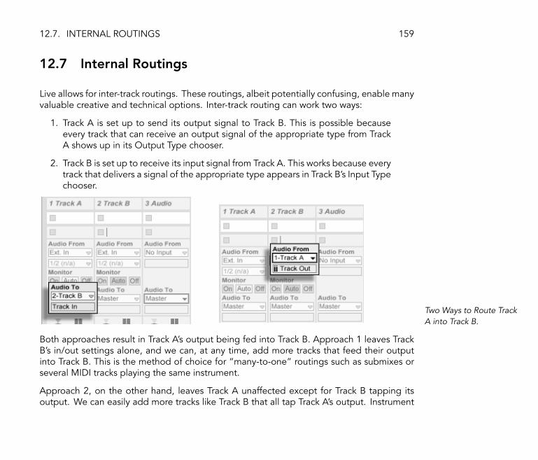
12.7. INTERNAL ROUTINGS 159
12.7 Internal Routings
Live allows for inter-track routings. These routings, albeit potentially confusing, enable manyvaluable creative and technical options. Inter-track routing can work two ways:
1. Track A is set up to send its output signal to Track B. This is possible becauseevery track that can receive an output signal of the appropriate type from TrackA shows up in its Output Type chooser.
2. Track B is set up to receive its input signal from Track A. This works because everytrack that delivers a signal of the appropriate type appears in Track B's Input Typechooser.
Two Ways to Route TrackA into Track B.
Both approaches result in Track A's output being fed into Track B. Approach 1 leaves TrackB's in/out settings alone, and we can, at any time, add more tracks that feed their outputinto Track B. This is the method of choice for �many-to-one� routings such as submixes orseveral MIDI tracks playing the same instrument.
Approach 2, on the other hand, leaves Track A unaffected except for Track B tapping itsoutput. We can easily add more tracks like Track B that all tap Track A's output. Instrument

12.7. INTERNAL ROUTINGS 160
layering is a good example of such a �one-to-many� routing setup.
The rest of this section presents internal routing examples in more detail.
12.7.1 Post-Effects Recording
Let's say that you are feeding a guitar into Live, building up a song track by track, overlayingtake onto take. It is certainly powerful to have a separate effects chain per track for applyingdifferent effects to different takes � after the fact. You might, however, want to run the guitarsignal through effects (a noise gate or an amp model, for instance) before the recordingstage, and record the post-effects signal.
An Example Setup forPre-Effects Recording.
This is easily accomplished by devoting a special audio track for processing and monitoringthe incoming guitar signal. We call this track �Guitar� and drag the desired effects into itsdevice chain. We do not record directly into the Guitar track; instead we create a couplemore tracks to use for recording. Those tracks are all set up to receive their input from theGuitar track.
As for monitoring, we set the Guitar track's Monitor radio button to In, because we alwayswant to listen to our guitar through this track, no matter what else is going on in Live. The
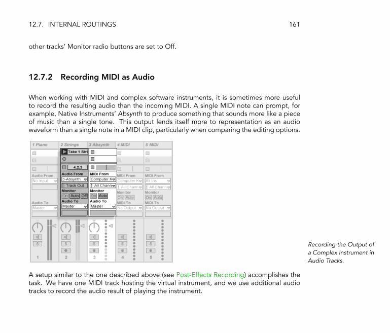
12.7. INTERNAL ROUTINGS 161
other tracks' Monitor radio buttons are set to Off.
12.7.2 Recording MIDI as Audio
When working with MIDI and complex software instruments, it is sometimes more usefulto record the resulting audio than the incoming MIDI. A single MIDI note can prompt, forexample, Native Instruments' Absynth to produce something that sounds more like a pieceof music than a single tone. This output lends itself more to representation as an audiowaveform than a single note in a MIDI clip, particularly when comparing the editing options.
Recording the Output ofa Complex Instrument inAudio Tracks.
A setup similar to the one described above (see Post-Effects Recording) accomplishes thetask. We have one MIDI track hosting the virtual instrument, and we use additional audiotracks to record the audio result of playing the instrument.
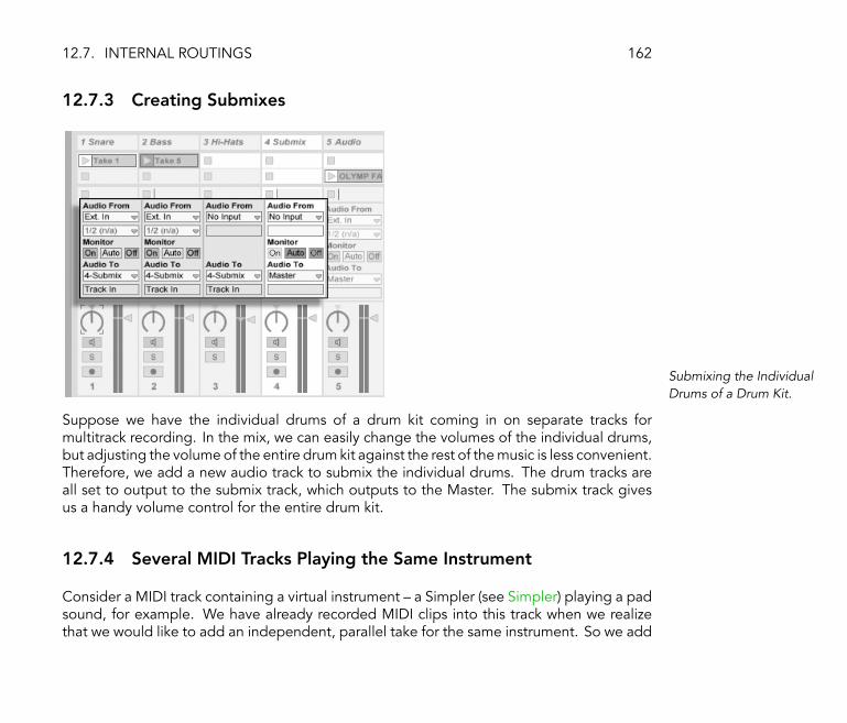
12.7. INTERNAL ROUTINGS 162
12.7.3 Creating Submixes
Submixing the IndividualDrums of a Drum Kit.
Suppose we have the individual drums of a drum kit coming in on separate tracks formultitrack recording. In the mix, we can easily change the volumes of the individual drums,but adjusting the volume of the entire drum kit against the rest of the music is less convenient.Therefore, we add a new audio track to submix the individual drums. The drum tracks areall set to output to the submix track, which outputs to the Master. The submix track givesus a handy volume control for the entire drum kit.
12.7.4 Several MIDI Tracks Playing the Same Instrument
Consider a MIDI track containing a virtual instrument � a Simpler (see Simpler) playing a padsound, for example. We have already recorded MIDI clips into this track when we realizethat we would like to add an independent, parallel take for the same instrument. So we add

12.7. INTERNAL ROUTINGS 163
another MIDI track. We could now drag another Simpler into the new track, but we wouldreally like to reuse the Simpler from the pad track, so that changing the pad's sound affectsthe notes from both tracks.
Feeding an AdditionalMIDI Track Into anExisting MIDI Track toReuse its Instrument.
This is accomplished by setting the new MIDI track's Output Type chooser to �Pad.� Notethat the Output Channel chooser now offers a selection of destinations: We can either feedthe new track's output into the input of the pad track, or we can directly address the Simpler.The �Track In� option in the Output Channel represents the pad track's input signal (thesignal to be recorded), which is not what we want. We instead select �Simpler Ch. 1� tosend the new track's MIDI directly to the Simpler, bypassing the recording and monitoringstage. With this setup, we can choose to record new takes on either track and they will allplay the same pad sound.
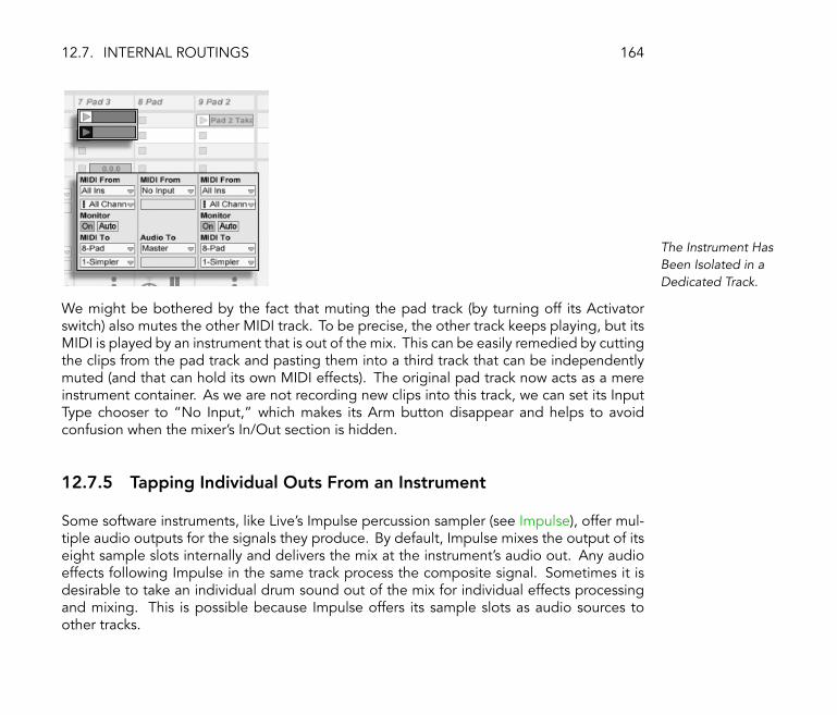
12.7. INTERNAL ROUTINGS 164
The Instrument HasBeen Isolated in aDedicated Track.
We might be bothered by the fact that muting the pad track (by turning off its Activatorswitch) also mutes the other MIDI track. To be precise, the other track keeps playing, but itsMIDI is played by an instrument that is out of the mix. This can be easily remedied by cuttingthe clips from the pad track and pasting them into a third track that can be independentlymuted (and that can hold its own MIDI effects). The original pad track now acts as a mereinstrument container. As we are not recording new clips into this track, we can set its InputType chooser to �No Input,� which makes its Arm button disappear and helps to avoidconfusion when the mixer's In/Out section is hidden.
12.7.5 Tapping Individual Outs From an Instrument
Some software instruments, like Live's Impulse percussion sampler (see Impulse), offer mul-tiple audio outputs for the signals they produce. By default, Impulse mixes the output of itseight sample slots internally and delivers the mix at the instrument's audio out. Any audioeffects following Impulse in the same track process the composite signal. Sometimes it isdesirable to take an individual drum sound out of the mix for individual effects processingand mixing. This is possible because Impulse offers its sample slots as audio sources toother tracks.

12.7. INTERNAL ROUTINGS 165
Using Impulse'sIndividual Outs toSeparately ProcessSample Slots.
We simply create an audio track and select from its Input Type chooser the track with theImpulse. The Input Channel chooser now offers, in addition to �Track Out� (the audio signalat the end of the track's device chain), Impulse's eight individual outputs, labeled accordingto the sample used in each slot. Notice that routing an individual output from Impulseinto another track automatically takes this signal out of Impulse's own internal mix. Thisconvenience is not standard behavior of most plug-in instruments, however.
12.7.6 Using Multi-Timbral Plug-In Instruments
Many plug-in instruments support multi-timbral operation. A multi-timbral instrument is likeseveral instruments in one, with each component �part� (or whatever term the manufactureruses) receiving MIDI on a separate MIDI channel. Usually, the multi-timbral instrument

12.7. INTERNAL ROUTINGS 166
offers individual outputs so that the parts can be separately routed into the mixer. Or, theinstrument might offer a submixer of its own.
Tracks Feeding MIDI toand Tapping AudioFrom the Parts of aMulti-TimbralInstrument.
Sending MIDI to a multi-timbral instrument is a variation of a case described above (seeSeveral MIDI Tracks Playing the Same Instrument). One MIDI track hosts the multi-timbralinstrument, and additional MIDI tracks are used to feed its individual parts. Each additionalMIDI track has its Output Type chooser pointed to the track that contains the instrument,and its Output Channel chooser referencing the target MIDI channel. Additional audiotracks can then be used to tap the instrument's individual outputs, as described earlier (seeTapping Individual Outs From an Instrument).
12.7.7 Feeding Sidechain Inputs
Some effects have so-called �sidechain inputs.� A vocoder, for instance, imposes spectralcharacteristics taken from one signal (say, spoken word) onto another signal, for instance astring pad. The vocoder is inserted as an audio effect into the string track. It has a sidechaininput for the speech signal, which has to be delivered from another track. So, we create an

12.7. INTERNAL ROUTINGS 167
additional audio track named �Speech� and set its Output Type chooser to the �Strings�track. From the Output Channel chooser, we select the vocoder's sidechain input.
Routing a Speech SignalInto a Vocoder'sSidechain Input.
Some vocoder plug-ins include a built-in synthesizer to generate the �carrier� signal. Inthis case, the only difference from the above procedure is that the vocoder instrument isdragged into a MIDI track. Feeding the side-chain audio input works as described above.
12.7.8 Layering Instruments
Suppose that we have a MIDI track containing an instrument playing a string sound, whichwe would like to �lubricate� by adding a brass sound playing the same notes. This can beeasily done by adding a MIDI track that contains an instrument playing the brass sound andsetting its Input Type chooser to tap the string track's output signal.
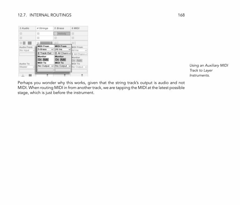
12.7. INTERNAL ROUTINGS 168
Using an Auxiliary MIDITrack to LayerInstruments.
Perhaps you wonder why this works, given that the string track's output is audio and notMIDI. When routing MIDI in from another track, we are tapping the MIDI at the latest possiblestage, which is just before the instrument.

Chapter 13
Mixing
13.1 The Live Mixer
Live includes a mixer section that is accessible from two views:
169
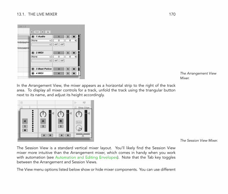
13.1. THE LIVE MIXER 170
The Arrangement ViewMixer.
In the Arrangement View, the mixer appears as a horizontal strip to the right of the trackarea. To display all mixer controls for a track, unfold the track using the triangular buttonnext to its name, and adjust its height accordingly.
The Session View Mixer.
The Session View is a standard vertical mixer layout. You'll likely �nd the Session Viewmixer more intuitive than the Arrangement mixer, which comes in handy when you workwith automation (see Automation and Editing Envelopes). Note that the Tab key togglesbetween the Arrangement and Session Views.
The View menu options listed below show or hide mixer components. You can use different
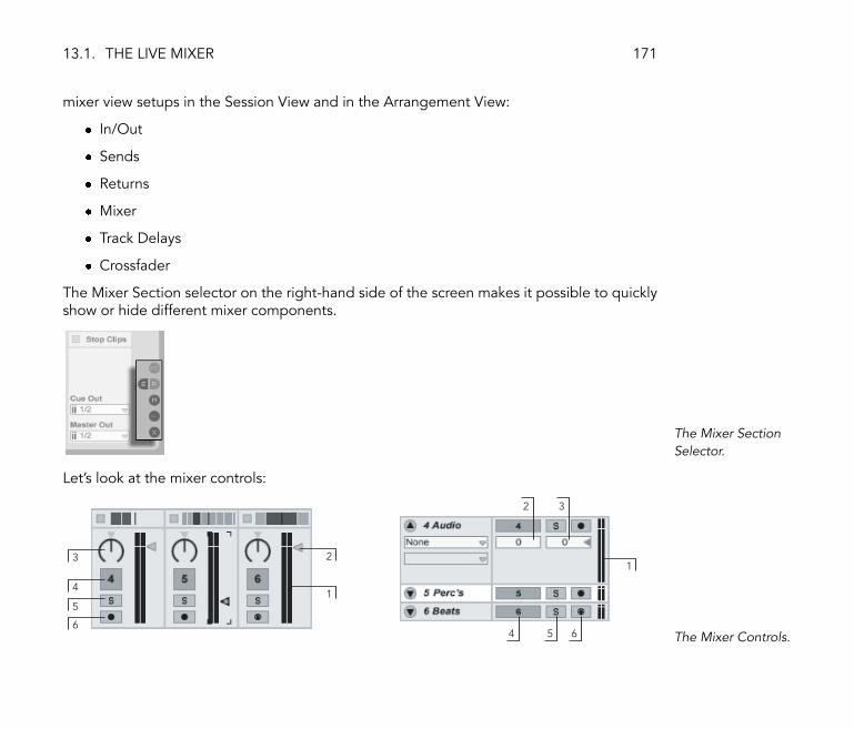
13.1. THE LIVE MIXER 171
mixer view setups in the Session View and in the Arrangement View:
� In/Out
� Sends
� Returns
� Mixer
� Track Delays
� Crossfader
The Mixer Section selector on the right-hand side of the screen makes it possible to quicklyshow or hide different mixer components.
The Mixer SectionSelector.
Let's look at the mixer controls:
1
21
3
6
5
4
4 5 6
32
The Mixer Controls.

13.2. AUDIO AND MIDI TRACKS 172
1. The Meter shows the track's RMS (average) and peak output level. While moni-toring, however, it shows the input level.
2. The Volume control adjusts the track's output level.
3. The Pan control positions the track's output in the stereo �eld. To reset the pancontrol to center, click on the little triangle.
4. To mute the track's output, turn off the Track Activator switch.
5. The Solo switch solos the track by muting all other tracks, but can also be used forcueing (see Soloing and Cueing). Tracks can only be soloed one at a time unlessthe Exclusive Solo option in the Misc Preferences is deactivated. Alternatively,you can hold down the Ctrl (PC) / (Mac) modi�er to solo more thanone track.
6. If the Arm Recording button is on, the track is record-enabled (see RecordingNew Clips). Tracks can only be armed one at a time unless the Exclusive Armoption in the Misc Preferences is deactivated. Alternatively, you can hold downthe Ctrl (PC) / (Mac) modi�er to arm more than one track.
13.2 Audio and MIDI Tracks
Audio and MIDI tracks in Live are for hosting and playing clips, as explained earlier (seeTracks).
You can add new audio and MIDI tracks to your Live Set's mixer at any time using theappropriate Insert menu commands.
Tracks can also be created by double-clicking or pressing Return on �les in the Browser toload them, or by dragging objects from the Browser into the space to the right of SessionView tracks or below Arrangement View tracks. Devices or �les loaded into Live in this

13.3. RETURN TRACKS AND THE MASTER TRACK 173
manner will create tracks of the appropriate type (e.g., a MIDI track will be created if a MIDI�le or effect is dragged in).
A track is represented by its track title bar. You can click on a track title bar to select thetrack and then execute an Edit menu command, such as �Rename,� on the track. One canquickly rename a series of tracks by executing this command and then using the Tab key tomove from title bar to title bar.
Tracks are Representedby Track Title Bars.
You can drag tracks by their title bars to rearrange them, or click and drag on their edges tochange their width (in the Session View) or height (in the Arrangement View).
Tracks are deleted using the Edit menu's Delete command.
13.3 Return Tracks and the Master Track
In addition to tracks that play clips, a Live Set has a Master track and up to twelve returntracks; these cannot play clips, but allow for more �exible signal processing and routing.
The return tracks and the Master track occupy the right-hand side of the Session mixer viewand the bottom end of the Arrangement View.
Note that you can hide and show the return tracks using the Returns command in the Viewmenu.
Like the �normal� clip tracks, the returns and the Master can host any number of effects(see Working with Instruments and Effects). However, whereas a clip track's effect processesonly the audio within that track, return tracks can process audio sent to them from numeroustracks.

13.3. RETURN TRACKS AND THE MASTER TRACK 174
For example, suppose you want to create rhythmic echoes with a delay effect. If you dragthe effect into a clip track, only clips playing in this track will be echoed. Placing this effectin a return track lets it receive audio from any number of tracks and add echoes to them.
The Send Controls andPre/Post Toggle.
A clip track's Send control regulates how much of the clip track's output feeds the associatedreturn track's input. What's more, even the return track's own output can be routed to itsinput, allowing you to create feedback. Please use this feature with care, as runawayfeedback can boost the level dramatically and unexpectedly.
Every return track has a Pre/Post toggle that determines if the signal a clip track sends toit is tapped before or after the mixer stage (i.e., the pan, volume and track-active controls).The �Pre� setting allows you to create an auxiliary mix that is processed in the return track,independently of the main mix. As the return track can be routed to a separate output(see Routing and I/O), this can be used to set up a separate monitor mix for an individualmusician in a band.
The Master track is the default destination for the signals from all other tracks. Drag effectshere to process the mixed signal before it goes to the master output. Effects in the Mastertrack usually provide mastering-related functions, such as compression and/or EQ.
You can create multiple return tracks using the Insert menu's Insert Return Track command,but by de�nition, there is only one Master track.

13.4. USING LIVE'S CROSSFADER 175
13.4 Using Live's Crossfader
Live includes a crossfader that can create smooth transitions between clips playing ondifferent tracks. Live's crossfader works like a typical DJ-mixer crossfader, except that itallows crossfading not only two, but any number of tracks � including the returns.
The crossfader is accessed via the Session View mixer.
The Crossfader.
The crossfader is a horizontal slider that can be mapped to any continuous MIDI controller(absolute or incremental) (see MIDI and Key Remote Control). In addition to the crossfader'scentral slider, its absolute left and right positions are separately available for MIDI or key-board mapping. There are two special scenarios for remote control with respect to thecrossfader:
� A key mapped to any one of the three assignable crossfader positions (left, center orright) will toggle the crossfader's absolute left and right positions.
� Mapping to two of the three �elds allows for a �snapping back� behavior when oneof the assigned keys is held down and the other is pressed and released.

13.4. USING LIVE'S CROSSFADER 176
A Track's CrossfadeAssign Buttons.
Each track has two Crossfade Assign buttons, A and B. The track can have three states withrespect to the crossfader:
� If neither Assign button is on, the crossfader does not affect the track at all.
� If A is on, the track will be played unattenuated as long as the crossfader is in the lefthalf of its value range. As the crossfader moves toward the right across the centerposition, the track fades out. At the crossfader's rightmost position, the track is muted.
� Likewise, if B is on, the track's volume will be affected only as the crossfader movesleft across its center position.
It is important to understand that the Crossfade Assign buttons do not affect the signalrouting: The crossfader merely in�uences the signal volume at each track's gain stage. Thetrack can be routed to an individual output bus regardless of its crossfade assignment. Instudio parlance, you can think of the crossfader as an on-the-�y VCA group.
As with almost everything in Live, your crossfading maneuvers can be recorded into theArrangement (see Automation and Editing Envelopes) for later in-depth editing. To edit eachtrack's crossfade assignment, please choose �Mixer� from the Envelope Device chooser and�X-Fade Assign� from the Control chooser. The crossfader's automation curve is accessiblewhen �Mixer� is chosen from the Master track's Device chooser and �Crossfade� is selectedfrom its Control chooser.

13.5. SOLOING AND CUEING 177
13.5 Soloing and Cueing
By default, soloing a track simply mutes all other tracks. The signal from the soloed tracksis heard through their respective outputs, with the pan setting of each track preserved.Soloing a clip track leaves the return tracks unaffected (solo in place). Soloing a return trackaffects all other tracks.
Live allows you to replace the standard soloing operation with a cueing operation that letsyou preview tracks as though you were cueing a record on a DJ mixer. This allows choosingclips and adjusting effects without the audience hearing, before bringing tracks into the mix.
In order to set Live up for cueing, you must be using an audio interface with at least fourdedicated outputs (or two dedicated stereo outputs). The respective settings are accessiblein the Session View mixer. Make sure you have �Mixer� and �In/Out� checked from theView menu.
124 35
The Cueing-RelatedSession Mixer Controls.
1. The Master Out chooser selects the output on your interface to be used as themain output.

13.6. TRACK DELAYS 178
2. The Cue Out chooser selects the output on your hardware interface to be usedfor cueing. This has to be set to an output other than that selected for the Master.If the desired outputs don't show up in these choosers, please check the AudioPreferences.
3. Activate cueing by setting the Solo/Cue Mode switch to �Cue.�
4. The tracks' Solo switches are now replaced by Cue switches with headphoneicons. When a track's Cue switch is pressed, that track's output signal will beheard through the output selected in the Cue Out chooser. Note that the TrackActivator switch on the same track still controls whether or not the track is heardat the Master output.
5. The Cue Volume control adjusts the volume of the cueing output.
Note that when cueing is set up and activated, the output of audio �les that you arepreviewing in the Browser is also heard through the Cue Out.
13.6 Track Delays
A Track Delay control is available for every track in Live. The control allows delaying or pre-delaying the output of tracks in milliseconds in order to compensate for human, acoustic,hardware and other real-world delays.
This section of the interface can be shown or hidden using its respective Mixer Sectionselector.

13.6. TRACK DELAYS 179
The Track Delay Controland Selector.
We do not recommend changing track delays on stage, as it could result in undesirableclicks or pops in the audio signal. Micro-offsets in Session View clips can be achieved usingthe nudge buttons in the Clip View (see Clip Offset and Nudging), however track delays canbe used in the Arrangement View for such offsets.
Note that delay compensation for plug-ins and Live devices (see Device Delay Compensation)is a separate feature, and is automatic by default. Unusually high Track Delay settings orreported latencies from plug-ins may cause noticeable sluggishness in the software. If youare having latency-related dif�culties while recording and playing back instruments, youmay want to try turning off device delay compensation, however this is not normally rec-ommended. You may also �nd that adjusting the individual track delays is useful in thesecases. Note that the Track Delay controls are unavailable when device delay compensationis deactivated.

Chapter 14
Recording New Clips
This chapter is about recording new clips from audio and MIDI input signals. Note that thisis a different kind of recording than the capturing of Session clips into the Arrangement (seeRecording Sessions into the Arrangement).
For successful audio recording, please make sure the audio preferences are set up properly.For more on this, please see the built-in program lesson on setting up Audio Preferences.Also, keep in mind that devices such as microphones, guitars and turntables do not operateat line level, meaning that they will need to have their levels boosted before they can berecorded. For these devices, you must therefore use either an audio interface with a preamp,or an external preamp.
180

14.1. CHOOSING AN INPUT 181
14.1 Choosing an Input
A track will record whatever input source is shown in its In/Out section, which appears whenthe View menu's �In/Out� option is checked. (In the Arrangement View, unfold and resizethe track in order to completely see the In/Out section.)
The Track In/Out Sectionin the Arrangement(Top) and Session View(Bottom).
Audio tracks default to recording a stereo signal from the external input pair �1/2.� MIDItracks default to recording all MIDI that is coming in through the active external inputdevices (see The Preferences' Active MIDI Device List). The computer keyboard is, bydefault, activated as a pseudo-MIDI input device (see Playing MIDI With the Computer
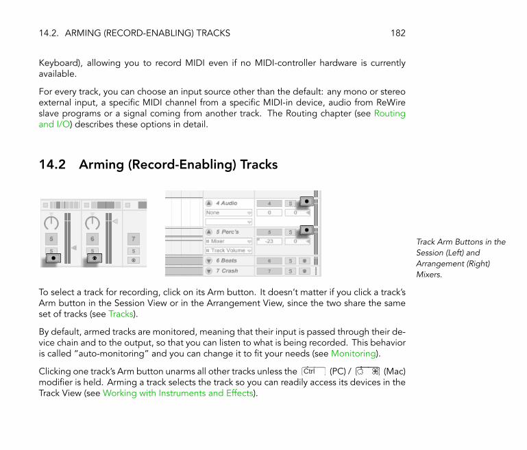
14.2. ARMING (RECORD-ENABLING) TRACKS 182
Keyboard), allowing you to record MIDI even if no MIDI-controller hardware is currentlyavailable.
For every track, you can choose an input source other than the default: any mono or stereoexternal input, a speci�c MIDI channel from a speci�c MIDI-in device, audio from ReWireslave programs or a signal coming from another track. The Routing chapter (see Routingand I/O) describes these options in detail.
14.2 Arming (Record-Enabling) Tracks
Track Arm Buttons in theSession (Left) andArrangement (Right)Mixers.
To select a track for recording, click on its Arm button. It doesn't matter if you click a track'sArm button in the Session View or in the Arrangement View, since the two share the sameset of tracks (see Tracks).
By default, armed tracks are monitored, meaning that their input is passed through their de-vice chain and to the output, so that you can listen to what is being recorded. This behavioris called �auto-monitoring� and you can change it to �t your needs (see Monitoring).
Clicking one track's Arm button unarms all other tracks unless the Ctrl (PC) / (Mac)modi�er is held. Arming a track selects the track so you can readily access its devices in theTrack View (see Working with Instruments and Effects).
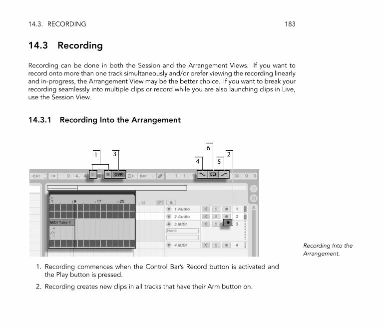
14.3. RECORDING 183
14.3 Recording
Recording can be done in both the Session and the Arrangement Views. If you want torecord onto more than one track simultaneously and/or prefer viewing the recording linearlyand in-progress, the Arrangement View may be the better choice. If you want to break yourrecording seamlessly into multiple clips or record while you are also launching clips in Live,use the Session View.
14.3.1 Recording Into the Arrangement
1 23
4 5
6
Recording Into theArrangement.
1. Recording commences when the Control Bar's Record button is activated andthe Play button is pressed.
2. Recording creates new clips in all tracks that have their Arm button on.
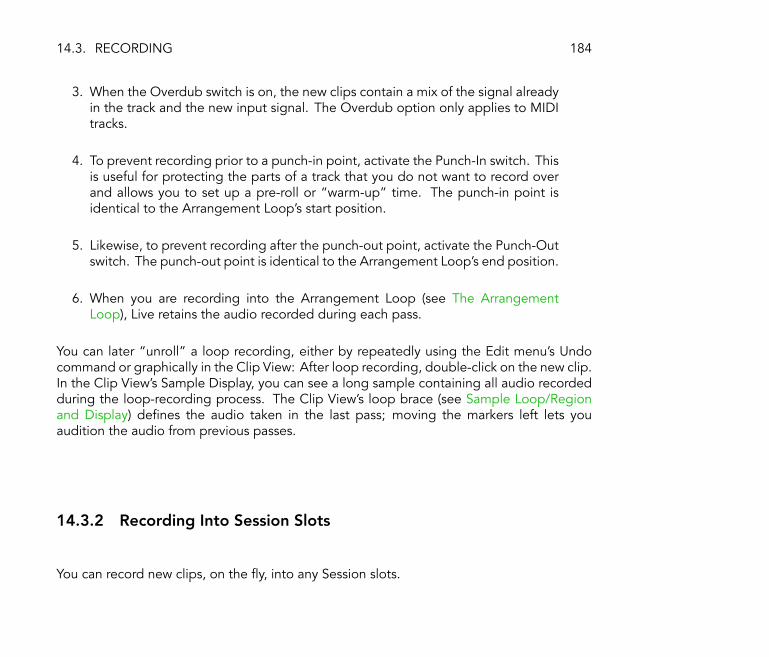
14.3. RECORDING 184
3. When the Overdub switch is on, the new clips contain a mix of the signal alreadyin the track and the new input signal. The Overdub option only applies to MIDItracks.
4. To prevent recording prior to a punch-in point, activate the Punch-In switch. Thisis useful for protecting the parts of a track that you do not want to record overand allows you to set up a pre-roll or �warm-up� time. The punch-in point isidentical to the Arrangement Loop's start position.
5. Likewise, to prevent recording after the punch-out point, activate the Punch-Outswitch. The punch-out point is identical to the Arrangement Loop's end position.
6. When you are recording into the Arrangement Loop (see The ArrangementLoop), Live retains the audio recorded during each pass.
You can later �unroll� a loop recording, either by repeatedly using the Edit menu's Undocommand or graphically in the Clip View: After loop recording, double-click on the new clip.In the Clip View's Sample Display, you can see a long sample containing all audio recordedduring the loop-recording process. The Clip View's loop brace (see Sample Loop/Regionand Display) de�nes the audio taken in the last pass; moving the markers left lets youaudition the audio from previous passes.
14.3.2 Recording Into Session Slots
You can record new clips, on the �y, into any Session slots.
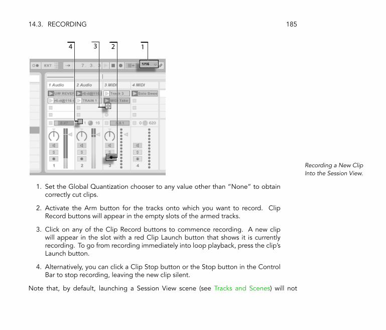
14.3. RECORDING 185
34 12
Recording a New ClipInto the Session View.
1. Set the Global Quantization chooser to any value other than �None� to obtaincorrectly cut clips.
2. Activate the Arm button for the tracks onto which you want to record. ClipRecord buttons will appear in the empty slots of the armed tracks.
3. Click on any of the Clip Record buttons to commence recording. A new clipwill appear in the slot with a red Clip Launch button that shows it is currentlyrecording. To go from recording immediately into loop playback, press the clip'sLaunch button.
4. Alternatively, you can click a Clip Stop button or the Stop button in the ControlBar to stop recording, leaving the new clip silent.
Note that, by default, launching a Session View scene (see Tracks and Scenes) will not

14.3. RECORDING 186
activate recording in empty record-enabled slots belonging to that scene. However, youcan use the Start Recording on Scene Launch option from the Misc Preferences to tell Livethat you do want empty scene slots to record under these circumstances.
14.3.3 Overdub Recording MIDI Patterns
Live makes pattern-oriented recording of drums and the like quite easy. Using Live's Impulse(see Impulse) instrument and the following technique, you can successively build up drumpatterns while listening to the result. Or, using an instrument such as Simpler (see Simpler),which allows for chromatic playing, you can build up melodies or harmonies, note by note.
1. Set the Global Quantization chooser to one bar.
2. To automatically quantize the notes you are about to record, choose an appro-priate value for Record Quantization (see Recording Quantized MIDI Notes).
3. Double-click any of the Session View slots in the desired MIDI track (the onecontaining the Impulse or other instrument). A new, empty clip will appear in theslot. The new clip will default to a loop length of one bar, but you can changethat by double-clicking the clip and changing its loop properties (see The NotesBox).
4. Arm the track.
5. Launch the clip.
6. The notes you play are added into the looping clip, and you can observe yourrecording in the Clip View.
7. By default, the Control Bar's Overdub switch is activated, so that you can buildyour pattern layer by layer. However, if you would like to pause recording for amoment to rehearse, you can deactivate the Overdub switch. The contents of

14.4. RECORDING IN SYNC 187
the clip will continue to play, but you can play along without being recorded.When you are ready to record again, simply turn on the Overdub switch.
8. Stop recording by pressing a Clip Stop button or the Stop button in the ControlBar.
Note that holding Alt (PC) / Alt (Mac) while double-clicking the empty slot to createa new clip will implicitly arm the track and launch the clip.
At any time while overdub recording is going on, you can use the Undo command to removethe last take, or even draw, move or delete notes in the Clip View's Note Editor.
Note that you can also add notes to existing Session clips while the Overdub switch is on.
14.4 Recording in Sync
Live keeps the audio and MIDI you have recorded in sync, even when you later decide on adifferent song tempo. In fact, Live allows you to change the tempo at any time before, afterand even during recording. You could, for instance, cheat a bit by turning down the tempoto record a technically dif�cult part, and pull it up again afterwards.
It is important to record in sync to make sure everything will later play in sync.
The Metronome Switch.
The easiest way to record in sync is to play along with or to use the built-in metronome,which is activated via its Control Bar switch and will begin ticking when the Play button ispressed or a clip is launched.

14.5. RECORDING QUANTIZED MIDI NOTES 188
The Preview VolumeKnob.
To adjust the metronome volume, use the mixer's Preview Volume knob.
Notice that Live's metrical interpretation of the audio being played can be edited, at anytime, using the Warp Markers (see Time-Warping Samples). Warp Markers can be used to �xtiming errors and to change the groove or feel of your recordings. Using Warp Markers, youcan �x things in your recordings that would otherwise require complicated editing or couldnot be done at all. Likewise, the metrical interpretation of recorded MIDI can be changedafter recording, using the MIDI clip's Original BPM controls (see The Notes Box).
14.5 Recording Quantized MIDI Notes
If you will be recording MIDI, you have the option of automatically quantizing MIDI noteswhile recording. The Record Quantization chooser in the Edit menu allows selecting themeter subdivisions with which your recorded notes will align. When recording into Sessionslots (see Recording Into Session Slots) or into the Arrangement (see Recording Into theArrangement), record quantization is an independent step in Live's Undo history. Thismeans that if, for example, you recorded with Record Quantization set to �Eighth NoteTriplet Quantization� and then changed your mind, using the Edit menu's Undo commandwould undo only the quantization and leave your recording otherwise intact.
For Session and Arrangement recording, the Record Quantization setting cannot be changedmid-recording.

14.6. RECORDING WITH COUNT-IN 189
When overdub recording (see Overdub Recording MIDI Patterns) with the Clip View Loopactivated, changes to the Record Quantization take effect immediately, and they cannot beseparately undone with the Edit menu command.
Recorded MIDI notes can also be quantized post-recording with the Edit menu's Quantizecommand, as described in the chapter on editing MIDI (see Arranging and QuantizingNotes).
14.6 Recording with Count-in
A count-in for recording can be set in Live's Misc Preferences. When the Count-In preferenceis set to any value other than �None,� Live will not begin recording until the count-in iscomplete. The Arrangement Position �elds in the Control Bar display the count-in in orangeas bars-beats-sixteenths.
The Count-In isDisplayed in the ControlBar.
The count-in runs from negative bars-beats-sixteenths (beginning at -2.1.1., for example,with a Count-In setting of 2 bars) up to 1.1.1., at which point recording commences.
Note that count-in recording does not apply when Live is synced to external MIDI devicesor being used as a ReWire slave (see Synchronization and ReWire).
14.7 Setting up File Types
The following Misc Preferences are relevant to the sample �les that are created by recording:

14.8. USING REMOTE CONTROL FOR RECORDING 190
� The sample �le type you would like Live to create can be chosen from the Record FileType chooser in the Misc Preferences.
� The bit depth of the sample �le you will create by recording can be chosen from theRecord Bit Depth chooser in the Misc Preferences.
� The Audio Record Folder selected in the Misc Preferences is the disk location whereLive will put the samples you record into an unnamed Live Set. When the Live Set issaved, Live will attempt to move (space permitting) all samples from the temporaryrecord folder to the saved Live Set's Sounds folder (see The Sounds Folder and Self-Containing).
You can save time by setting up reasonable defaults for the clips you are recording in theDefaults Preferences tab. In particular, it is smart to indicate the rough category of soundto be recorded by choosing the appropriate default Warp Mode. If you decide later ona different song tempo, the program will automatically maintain good sound quality (seeAdjusting for Good Stretching Quality), usually without further adjustment.
14.8 Using Remote Control for Recording
Using Key Map Mode and MIDI Map Mode (see MIDI and Key Remote Control), you canoperate Live's recording functions without using the mouse.
You can map the Control Bar's Record and transport controls as well as the track Arm buttons.For recording into the Session slots, you can map the individual slots as well as the relativenavigation controls to initiate recording remotely; for instance:
The Scene Up/DownButtons.

14.8. USING REMOTE CONTROL FOR RECORDING 191
One key is used to jump to the next scene...
A Track Launch Button.
... and another key to start and end recording in the respective track.

Chapter 15
Working with Instruments andEffects
Every track in Live can host a number of devices. These devices can be of three differentsorts:
� MIDI effects act upon MIDI signals and can only be placed in MIDI tracks.
� Audio effects act upon audio signals and can be placed in audio tracks. They can alsobe placed in MIDI tracks as long as they are �downstream� from an instrument.
� Instruments are devices that reside in MIDI tracks, receive MIDI and output audio.
192

193
Devices in the TrackView.
The Track View is where you insert, view and adjust the devices for the selected track. Toselect a track and open the Track View to access its devices, double-click the track's name.The Track View appears in the bottom area of the Live screen.

15.1. USING THE LIVE DEVICES 194
15.1 Using the Live Devices
The Live Device BrowserSelector.
Click on the Live Device Browser selector to access the palette of Live's built-in devices. Youwill notice that MIDI effects, audio effects and instruments each have their own folders inthe Browser.
To place one instance of a device in a track, click on the desired device and drag it into theTrack View of an appropriate track. You can also select a track by clicking on its title bar,then double-click or press Return on a device in the Browser to add it to the selected track.
Note: If you are using an external input signal to feed your Live track using the defaultsettings, you will need to activate the track's Arm button in the mixer in order to hear theinput through the devices in your track's device chain. This is how you would play liveinstruments through effects on a track, for example, or use a MIDI keyboard's input to playa track's instrument. Note that you can easily move from this setup into recording newclips (see Recording New Clips) for further use in Live. If you have alternative monitoringpreferences, please see the appropriate manual section (see Monitoring) for information onhow to make these settings.

15.1. USING THE LIVE DEVICES 195
MIDI and Audio TrackArm Buttons
Play with the device's controls to change the result, or get more �hands-on� by assigningdevice controls to MIDI or key remote control (see MIDI and Key Remote Control). To learnwhat a device does and how to operate it, consult the Live Audio Effect Reference chapter(see Live Audio Effect Reference), Live MIDI Effect Reference chapter (see Live MIDI EffectReference) or the Live Instrument Reference chapter (see Live Instrument Reference).
To add another device to the track, simply drag it there or double-click its name to appendit to the device chain. Signal processing travels from left to right on the track.
� You can drop audio effects in at any point in an audio track's device chain, keepingin mind that the order of effects determines the resulting sound, as effects on the leftwill pass altered signals on to those on the right.
� The above also applies to a MIDI track's device chain.
� If you drop an instrument into a MIDI track's device chain, signals following (to theright of) the instrument are now audio signals, available only to audio effects. Signalspreceding (to the left of) the instrument are available only to MIDI effects. This meansthat it is possible to have a MIDI track device chain consisting of all three types ofdevices: �rst a MIDI effect, then an instrument, and �nally an audio effect.

15.1. USING THE LIVE DEVICES 196
A MIDI Track's DeviceChain Can Contain AllThree Device Types.
To remove a device from the chain, click on the name and either press your computer'sDelete or Backspace key, or select Delete from the Edit menu. To change the order ofdevices, drag a device by its name and drop it between any of the other devices in the TrackView, or drag it onto another track in the mixer to place the device in that track. Generally,devices can be placed, reordered and deleted without interrupting the audio stream.
A Device ActivatorSwitch.
Devices can be turned on and off using their Activator switches. Turning a device off is liketemporarily deleting it: The signal remains unprocessed, and the device does not consumeCPU cycles. Live devices generally do not load down the CPU unless they are active. Formore information, please refer to the CPU load section (see Managing the CPU Load). Notethat the Freeze Track command mentioned in the CPU load section is especially helpfulwhen working with CPU-intensive devices.
Devices in Live's tracks have input and output level meters. These meters facilitate �ndinga problematic device in the device chain: Low or absent signals will be apparent in the levelmeters between devices, and relevant device settings can then be adjusted, or the devicecan be turned off or removed. Note that no clipping can occur between devices because

15.1. USING THE LIVE DEVICES 197
there is practically unlimited headroom. Clipping can occur when an overly strong signal issent to a physical output or written to a sample.
Further information about track types in Live can be found in the Routing and I/O chapter(see Routing and I/O), including information on using return tracks to distribute the effectof a single Live device amongst several tracks. After reading about using devices in Live, itmight also be interesting look into clip envelopes (see Clip Envelopes), which can modulateindividual device settings on a per-clip basis.
15.1.1 Live Device Presets
Every Live device can store and retrieve particular sets of parameter values as presets.
Browsing and Loading Presets
Presets for Live instruments and effects are managed through the Live Device Browser. Eachdevice in the Browser appears as a folder that can be opened to reveal its presets.

15.1. USING THE LIVE DEVICES 198
Presets in the DeviceBrowser.
You can browse and load presets quickly with the computer keyboard:
� Scroll up and down using the and keys.
� Close and open device folders using the and keys.
� Use (PC) / Ctrl (Mac) to access the context menu, and then select the CloseAll Folders option to show only top-level folders. Double-clicking the Device Browsericon will also close all sub-level folders.
� Press Return to load a device or preset.
The Browse PresetsButton.

15.1. USING THE LIVE DEVICES 199
Clicking the Browse Presets button will temporarily link the Browser to a device, bringingup the relevant presets in the Browser. With the device and Browser linked in this manner,you can quickly browse, load and audition different presets. You can even load a differentdevice to replace the current one by selecting one of the new device's presets from theBrowser and pressing Return . To load a device's default factory settings, select the parentfolder of its presets (i.e., the one with the device's name) from the Device Browser.
The link between the Device Browser and the device will be broken when a different Liveview is selected, or when the Browse Presets button is again pressed.
Note that although importing via the Browser is the recommended method, presets canalso be dropped directly into Live from the Explorer (Windows) / Finder (Mac).
Saving and Organizing Presets
You can create and save any number of your own presets in the Device Browser.
The Preset Save Button.
Click the Preset Save button to save a new preset. You can then con�rm Live's suggestedname or type in one of your own.
Note that a preset with unsaved changes is shown in the Device Browser with an asterisknext to its name.
Presets can be organized in the Browser in a manner similar to �les (see File Maintenance inthe Browser):

15.1. USING THE LIVE DEVICES 200
� They can be put in sub-folders with the aid of the (PC) / Ctrl (Mac) contextmenu's Create Folder command.
� Presets can be moved to different folders within their device's folder by dragging anddropping, or by copying/cutting and pasting.
� Presets can be renamed using the Edit menu's Rename command or the Ctrl R
(PC) / R (Mac) shortcut.
� To delete a preset, select it and press your computer's Delete key, or use the respectiveEdit menu command.
Searching for Presets
Live's search function is available in the Device Browser to help with �nding presets by name.
Opening Search Modein the Device Browser.
Clicking the Search button in the upper right corner of the Device Browser or using theCtrl F (PC) / F (Mac) shortcut will open the Browser's Search Mode.
Live will search for the contents typed in the Search �eld throughout the Device Browser.After entering search criteria, begin the search by pressing Return on your computer key-board.
You can abort an in-progress search with the Exit Search button located to the right of theSearch �eld. A second click on this button closes Search Mode, returning the Browser to

15.1. USING THE LIVE DEVICES 201
Browse Mode. Beginning a new search aborts any current searches by default.
Exiting Search Mode.
A useful feature of Live's Browser search function is the Locate In Browser button, found tothe right of the Search �eld. After �nding a particular preset in Search Mode, you can selectit and click this button to open the preset in Browse Mode, where its location in the folderhierarchy will be displayed.
The Locate In BrowserButton.
15.1.2 Device Groups
Device groups allow you to save powerful multi-device creations, effectively adding all thecapabilities of Live's MIDI and audio effects to Simpler, Impulse and Operator presets.
To create a device group, multi-select any number of devices in the Track View by -clicking on their title bars. Then, select the Edit menu's Group Devices command, use the
Ctrl G (PC) / G (Mac) shortcut, or select �Group Devices� from the (PC) /Ctrl (Mac) context menu. The devices will �melt� into one new device.

15.2. USING PLUG-INS 202
A Device Group in theTrack View.
The entire device group, along with its component device settings, can be stored as a presetby clicking its Preset Save button and typing a new name in the Device Browser. Groupscontaining an instrument are stored with the respective instrument in the Device Browser;groups without an instrument appear in the �MIDI Effect Groups� or �Audio Effect Groups�folders.
Device groups can be browsed, loaded, organized, searched and used just like single-devicepresets (see Live Device Presets).
Devices can be ungrouped via the Ungroup Edit menu command, Ctrl G (PC) / G
(Mac) shortcut or respective (PC) / Ctrl (Mac) context menu command.
15.2 Using Plug-Ins
The collection of devices that you use in Live can be extended with plug-ins. Live supportsSteinberg Media's VST Plug-ins and Apple Computer's Audio Units Plug-ins (Mac OS X only).

15.2. USING PLUG-INS 203
Working with VST and Audio Units Plug-ins is very much like working with Live devices. VSTand Audio Units instruments can only be placed in Live MIDI tracks and, like Live instruments,they will receive MIDI and output audio signals. Plug-in audio effects can only be placed inaudio tracks or following instruments. Please see the section on working with Live devices(see Using the Live Devices) for general information about working with devices in Live.
The Plug-In DeviceBrowser and Selector.
Audio Units and VST Plug-ins are browsed and imported using the Plug-In Device Browser,which is accessed via its selector. Plug-in instruments can be differentiated from plug-ineffects in the Browser, as they appear with a keyboard icon.
The Browser's search functionality is only available for Audio Units Plug-ins, as is loadingpresets directly from Track View devices via the Browse button. In some instances, factorypresets for Audio Units will only appear in the Browser once the device has been placed ina track and its Browse button activated.
Note: The �rst time you start Live, no plug-ins will appear in the Plug-In Device Browser,as you must �rst �activate� your plug-in sources. Activating your plug-in sources tells Livewhich plug-ins you want to use and where they are located on your computer. Informationon activating (and deactivating) plug-in sources can be found later in this chapter, by plug-intype, in the sections on the VST Plug-in folder (see The VST Plug-In Folder) and Audio UnitsPlug-ins (see Audio Units Plug-Ins).

15.2. USING PLUG-INS 204
If you install/de-install a plug-in while the program is running, Live will not detect yourchanges or implement them in the Plug-In Device Browser until the next time you start theprogram. Use the Re-Scan button in the Plug-In Preferences to re-scan your plug-ins whileLive is running, so that newly installed devices become immediately available in the Plug-InDevice Browser.
Hint: You can also use Re-Scan if you believe that your plug-in database has somehowbecome corrupted. Holding down the Alt (PC) / Alt (Mac) modi�er while pressingRe-Scan will delete your plug-in database altogether and run a clean scan of your plug-ins.
15.2.1 Plug-Ins in the Track View
A VST Plug-In in theTrack View.
Once a plug-in is dragged from the Browser into a track, it will show up in the track's TrackView. The original plug-in panel graphics will be replaced with a Live panel, which willusually represent all of the plug-in parameters accurately and completely, unless they aresimply too numerous or are not modi�able in real time. When this is the case, the plug-in'soriginal editor panel can be opened in a separate window (see Showing Plug-In Panels inSeparate Windows).

15.2. USING PLUG-INS 205
The Plug-In UnfoldButton.
You can view or hide the VST Plug-in's parameters by toggling the triangle-shaped buttonin the plug-in's title bar.
The X-Y control �eld can be used to control two plug-in parameters at once and is thereforeespecially well-suited for live control. To assign any two plug-in parameters to the Live panelX-Y �eld, use the drop-down menus directly beneath it.
Once a plug-in is placed in a track, you can use it just like a Live device:
� You can edit all of its parameters and drag it to different locations in the device chainor to other tracks, according to the rules of audio effects and instruments.
� You can map MIDI-controller messages to its parameters (see MIDI and Key RemoteControl).
� You can modulate its continuous parameters with clip envelopes (see Clip Envelopes).
� You can also use the multiple I/O features of some plug-ins by assigning them assources or targets in the routing setup of tracks. See the chapter on routing (seeRouting and I/O) for details.

15.2. USING PLUG-INS 206
15.2.2 Showing Plug-In Panels in Separate Windows
The Plug-In Edit Button.
The Plug-In Edit button opens a �oating window that shows the original VST or Audio UnitsPlug-in panel. Changing parameters on the �oating window has the same effect as changingthem in the Live panel, and vice versa.
There are a few important Plug-In Preference settings for working with plug-in edit windows:
� If activated, the Auto-Open Plug-In Windows Preference assures that plug-in editwindows open automatically when plug-ins are loaded into tracks from the Browser.
� If the Multiple Plug-In Windows option in the Plug-In Preferences is activated, you canopen any number of plug-in windows at once. Even with this option off, you can holddown the Ctrl (PC) / (Mac) modi�er when opening a new plug-in window tokeep the previous window(s) from closing.
� Using the Auto-Hide Plug-In Windows preference, you can choose to have Live displayonly those plug-in windows belonging to the track that is currently selected.
You can use the View menu's Show/Hide Plug-In Windows command or the Ctrl P (PC)/ P (Mac) shortcut to hide and show your open plug-in windows. Notice that thename of the track to which the plug-in belongs is displayed in the title bar of the plug-ineditor window.
Macintosh only: The �oating VST Plug-in editor windows do not receive computer keystrokes. If it is necessary to type into the plug-in window, for instance for entering a serialnumber or unlock code, hold down while clicking the Plug-In Edit button. The editorwindow will then appear as a �normal� application window, rather than as a �oating window,

15.3. VST PLUG-INS 207
and receive your typing. Note that this functionality is intended only as a workaround for aplug-in limitation. We recommend closing the window after you have �nished typing, thenreopening it normally before working with the plug-in parameters.
15.2.3 Plug-In Performance Options
The Plug-In Preferences contain a Performance setting for balancing plug-in latency andperformance. Here, you can set the number of samples processed at any one time by theplug-in. Higher settings may result in a noticeable performance increase but will also resultin higher latencies.
With the �As Audio Buffer� setting selected, the plug-in will calculate the exact number ofsamples per millisecond as the computer's sound card. This setting usually means that veryfew dropouts or performance problems will occur, especially with DSP cards.
The size of the computer's sound card buffer (i.e., the number of samples it calculates permillisecond) can be set using the Audio Preferences Buffer Size setting.
15.3 VST Plug-Ins
15.3.1 The VST Plug-In Folder
When you start Live for the �rst time, you will need to activate your VST Plug-in sourcesbefore working with VST Plug-ins. Depending on your computer platform, you may alsohave to tell Live about the location of the VST Plug-in folder containing the devices youwant to use. In order to set up your VST sources, press the �Activate� button in the Plug-InDevice Browser, or go to the Plug-In Preferences via the Options menu (or the Live menu inMac OS X). There you will �nd the �Active Sources� section.

15.3. VST PLUG-INS 208
Setting up VST Plug-InSources for Windows.
For Windows, proceed as follows:
1. Use the VST Plug-In Custom Folder entry to tell Live about the location of yourVST Plug-ins: Click the Browse button to open a folder-search dialog for locatingand selecting the appropriate folder.
2. Once you have selected a VST Custom Folder and Live has scanned it, the pathwill be displayed. Note that, on Windows, Live may have found a path in theregistry without the need for browsing.
3. Make sure that the Use VST Plug-In Custom Folder option is set to �On,� sothat your selected folder is an active source for VST Plug-ins in Live. Note thatyou can choose not to use your VST Plug-ins in Live by turning off the Use VSTPlug-In Custom Folder option.
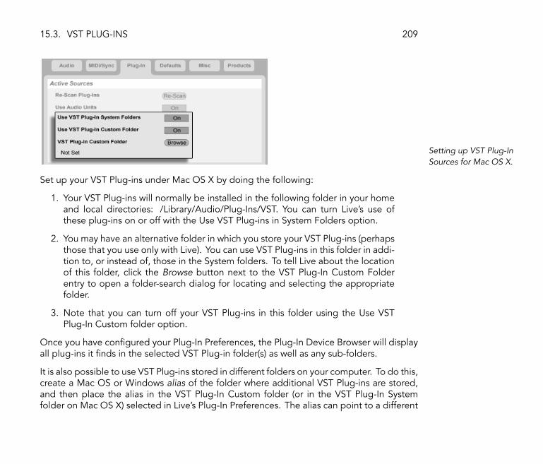
15.3. VST PLUG-INS 209
Setting up VST Plug-InSources for Mac OS X.
Set up your VST Plug-ins under Mac OS X by doing the following:
1. Your VST Plug-ins will normally be installed in the following folder in your homeand local directories: /Library/Audio/Plug-Ins/VST. You can turn Live's use ofthese plug-ins on or off with the Use VST Plug-ins in System Folders option.
2. You may have an alternative folder in which you store your VST Plug-ins (perhapsthose that you use only with Live). You can use VST Plug-ins in this folder in addi-tion to, or instead of, those in the System folders. To tell Live about the locationof this folder, click the Browse button next to the VST Plug-In Custom Folderentry to open a folder-search dialog for locating and selecting the appropriatefolder.
3. Note that you can turn off your VST Plug-ins in this folder using the Use VSTPlug-In Custom folder option.
Once you have con�gured your Plug-In Preferences, the Plug-In Device Browser will displayall plug-ins it �nds in the selected VST Plug-in folder(s) as well as any sub-folders.
It is also possible to use VST Plug-ins stored in different folders on your computer. To do this,create a Mac OS or Windows alias of the folder where additional VST Plug-ins are stored,and then place the alias in the VST Plug-In Custom folder (or in the VST Plug-In Systemfolder on Mac OS X) selected in Live's Plug-In Preferences. The alias can point to a different

15.3. VST PLUG-INS 210
partition or hard drive on your computer. Live will scan the set VST Plug-in folder as well asany alias folders contained therein.
Some VST Plug-ins contain errors or are incompatible with Live. During the scanning process,these may cause the program to crash. When you re-launching Live, a dialog will appearto inform you about which plug-in caused the problem. Depending on what Live detectsabout the plug-in, you may be given the choice between performing another scan ormaking the problematic plug-in unavailable. If you choose to re-scan and they crash theprogram a second time, Live will automatically make them unavailable, meaning that theywill not appear in the Plug-In Device Browser and will not be re-scanned again until they arereinstalled.
15.3.2 VST Programs and Banks
Every VST Plug-in instance �owns� a bank of programs. A program is meant to contain onecomplete set of values for the plug-in's controls.
The VST Plug-InProgram Chooser.
To select a program from the plug-in's bank, use the chooser below the title bar. The numberof programs per bank is �xed. You are always working �in� the currently selected program,that is, all changes to the plug-in's controls become part of the selected program.
Note that VST programs are different from Live device presets LiveDevicePresets (see LiveDevice Presets): Whereas the presets for a Live device are shared among all instances andLive Sets, the VST programs �belong� to this speci�c instance of the VST Plug-in.

15.3. VST PLUG-INS 211
Renaming a VST Plug-InProgram.
To rename the current program, select the VST program chooser and execute the Editmenu's Rename Plug-In Preset command. Then type in a new program name and con�rmby pressing Return.
The VST Program/BankLoad Button (Left) andThe VST Program/BankSave Button (Right).
VST programs and banks can be imported from �les. Clicking the VST Program Load buttonbrings up a standard �le-open dialog for locating the desired �le.
Windows only: Please select from the File Type menu whether you want to locate VSTDevice Program �les or VST Device Bank �les.
To save the currently selected program as a �le, click the VST Program/Bank Save button tobring up a standard �le-save dialog; select �VST Device Program� from the Format menu(Macintosh) / from the File Type menu (Windows); select a folder and name. For saving theentire bank as a �le, proceed likewise but choose �VST Device Bank� as a �le type/format.

15.4. AUDIO UNITS PLUG-INS 212
15.4 Audio Units Plug-Ins
Audio Units Plug-ins are only available in Mac OS X. In most respects, they operate just likeVST Plug-ins (see VST Plug-Ins).
An Audio Units Plug-In.
The �rst time you open Live, Audio Units Plug-ins will not appear in the Plug-In DeviceBrowser. In order to activate your Audio Units as a plug-in source, please press the �Activate�button in the Plug-In Device Browser, or go to the Plug-In Preferences via the Live menu.There you will �nd the �Active Sources� section. Turning on the Use Audio Units optionactivates Audio Units Plug-ins so that they appear in Live's Plug-In Device Browser.
Note that you can always turn this option off later if you decide not to use Audio Units.

15.4. AUDIO UNITS PLUG-INS 213
Activating Audio UnitsPlug-Ins.
Audio Units Plug-ins sometimes have a feature that allows choosing between differentmodes for the device. You might be able to choose, for example, between different levelsof quality in the rendering of a reverb. Choosers for these device modes can only beaccessed through the original plug-in panel, which is opened using the Plug-In Edit button.
Opening an Audio UnitsPlug-In Window.
Audio Units have presets that function just like those for the Live effects (see Live DevicePresets). However, some AU presets cannot be dragged to different locations in the Browser,as they are read-only.
Audio Units presets have an .aupreset extension and are stored in the following directoryaccording to their manufacturer's name:
[Home]/Library/Audio/Presets/[Manufacturer Name]/[Plug-in Name]

15.5. DEVICE DELAY COMPENSATION 214
15.5 Device Delay Compensation
Live automatically compensates for delays caused by Live and plug-in instruments andeffects, including those on the return tracks. These delays can arise from the time taken bydevices to process an input signal and output a result. The compensation algorithm keepsall of Live's tracks in sync, regardless of what their devices are doing, while minimizing delaybetween the player's actions and the audible result.
Device delay compensation is on by default and does not normally have to be adjusted inany way. However, Live Sets that were created with older versions of Live will open withoutdevice delay compensation. To manually turn latency compensation on (or off), use theDelay Compensation option in the Options menu.
Unusually high individual track delays (see Track Delays) or reported latencies from plug-ins may cause noticeable sluggishness in the software. If you are having latency-relateddif�culties while recording and playing back instruments, you may want to try turning offdevice delay compensation, however this is not normally recommended. You may also �ndthat adjusting the individual track delays is useful in these cases.
Note that device delay compensation can, depending on the number of tracks and devicesin use, increase the CPU load.

Chapter 16
Automation and Editing Envelopes
Often, when working with Live's mixer and devices, you will want the controls' movementsto become part of the music. The movement of a control across the song timeline is calledautomation; a control whose value changes in the course of this timeline is automated.Practically all mixer and device controls in Live can be automated, including the songtempo.
16.1 Recording Automation
Creating automation is straightforward: All changes of a control that occur while the ControlBar's Record switch is on become automation. Try recording automation for a control, forinstance a mixer volume slider. After recording, play back what you have just recordedto see and hear the effect of the control movement. You will notice that a little LED hasappeared in the slider thumb to indicate that the control is now automated. Try recording
215

16.2. DELETING AUTOMATION 216
automation for track panning and the Track Activator switch as well; their automation LEDsappear in their upper left corners.
Volume, Pan and theTrack Activator SwitchHave Been Automated.
16.2 Deleting Automation
To delete automation data, simply select an automated control by clicking on it, and choosethe Edit menu's Delete Automation command. The automation LED disappears, and thecontrol's value stays constant across the entire song. Note that this will not work withcontrols that are switches, like the Track Activator switch, because they cannot be selected byclicking. You can only delete automation for switches by editing their breakpoint envelopes(see Drawing and Editing Automation).
16.3 Overriding Automation
In practice, you will often want to try out new control moves without overwriting existingautomation data. Well, nothing is forever in the world of in�nite Undo (see Non-DestructiveEditing), but it's easy to disable a control's automation temporarily to avoid overwritingexisting data: If you change an automated control's value while not in Record Mode, theautomation LED goes off to indicate the control's automation is inactive. Any automation istherefore overridden by the current manual setting.
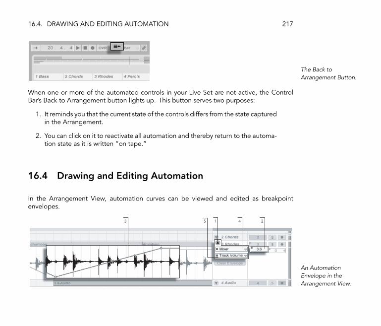
16.4. DRAWING AND EDITING AUTOMATION 217
The Back toArrangement Button.
When one or more of the automated controls in your Live Set are not active, the ControlBar's Back to Arrangement button lights up. This button serves two purposes:
1. It reminds you that the current state of the controls differs from the state capturedin the Arrangement.
2. You can click on it to reactivate all automation and thereby return to the automa-tion state as it is written �on tape.�
16.4 Drawing and Editing Automation
In the Arrangement View, automation curves can be viewed and edited as breakpointenvelopes.
15 4 23
An AutomationEnvelope in theArrangement View.

16.4. DRAWING AND EDITING AUTOMATION 218
1. To access a track's envelope, �unfold� the track by clicking the triangular buttonnext to the track name.
2. Clicking on one of the track's mixer or device controls will display this control'senvelope.
3. The envelope appears �on top of� the audio waveform or MIDI display. Itsvertical axis represents the control value and the horizontal axis represents time.For switches and radio buttons, the value axis is discontinuous.
4. The Automation Device chooser either selects the track mixer, one of the track'sdevices or �None� to hide the envelope. It also provides you with an overviewof what devices actually have automation by showing an LED next to their labels.
5. The Automation Control chooser selects a control from the device chosen in theAutomation Device chooser. The labels of automated controls have an LED.
16.4.1 Drawing Envelopes
With Draw Mode enabled, you can click and drag to �draw� an envelope curve.
The Draw Mode Switch.
To toggle Draw Mode, select �Draw Mode� from the Options menu, click on the ControlBar's Draw Mode switch, or press Ctrl B (PC) / B (Mac).
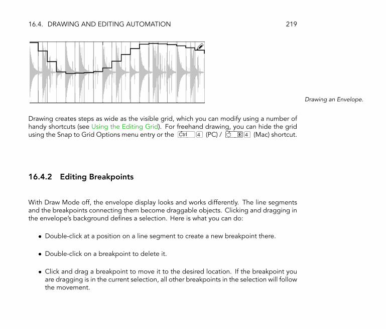
16.4. DRAWING AND EDITING AUTOMATION 219
Drawing an Envelope.
Drawing creates steps as wide as the visible grid, which you can modify using a number ofhandy shortcuts (see Using the Editing Grid). For freehand drawing, you can hide the gridusing the Snap to Grid Options menu entry or the Ctrl 4 (PC) / 4 (Mac) shortcut.
16.4.2 Editing Breakpoints
With Draw Mode off, the envelope display looks and works differently. The line segmentsand the breakpoints connecting them become draggable objects. Clicking and dragging inthe envelope's background de�nes a selection. Here is what you can do:
� Double-click at a position on a line segment to create a new breakpoint there.
� Double-click on a breakpoint to delete it.
� Click and drag a breakpoint to move it to the desired location. If the breakpoint youare dragging is in the current selection, all other breakpoints in the selection will followthe movement.

16.4. DRAWING AND EDITING AUTOMATION 220
To Move all BreakpointsWithin the Selection,Drag Any One of Them.
Your movement is constrained by the neighboring breakpoints unless you hold downthe modi�er while dragging, which will eliminate breakpoints as you wipe overthem. Holding down the Ctrl (PC) / (Mac) modi�er while dragging switchesto a �ner resolution.
� Click and drag a line segment between two breakpoints to move it vertically, withoutaffecting the breakpoint's horizontal position. If the line segment is in the currentselection, the envelope is moved vertically across the selected timespan. Live insertsbreakpoints at the selection's edges to make sure the move only affects the selectedpart of the envelope.
Dragging an EnvelopeLine Segment Moves theSegment Vertically.
16.4.3 Locking Envelopes
When moving clips, Live normally moves all automation with the clip. Sometimes, youmight want to lock the envelopes to the song position rather than to the clips, and theArrangement View's Lock Envelopes switch does just that.

16.4. DRAWING AND EDITING AUTOMATION 221
You can also choose to lock envelopes from the Options menu.
The Lock EnvelopesSwitch.
16.4.4 Edit Menu Commands
There are a number of useful Edit menu commands for editing envelopes.
To cut or copy automation from a track, independent of the associated clip, use the Editmenu's Cut Envelope and Copy Envelope commands, respectively.
To simultaneously copy and paste a selection of envelope into a track's �future,� use theDuplicate Envelope command.
Note that Live allows you to copy and paste envelope movements not only from one pointin time to another, but also from one parameter to another. However, there is obviously nomeaningful conversion from a pan movement to, say, an equalizer frequency, and all Livecan do is somehow preserve the gesture.
16.4.5 Editing the Tempo Automation
The ability to dynamically stretch and compress audio to track any tempo or tempo variationis one of Live's specialties. In Live, the song tempo is just another automated control.
To edit the song tempo envelope, unfold the Master track, choose �Mixer� from the topenvelope chooser and �Song Tempo� from the bottom one.

16.4. DRAWING AND EDITING AUTOMATION 222
The Tempo Envelope.
When adjusting the tempo envelope, you might want to scale the value axis display, whichis the function of the two value boxes below the envelope choosers: The left box sets theminimum, and the right box sets the maximum tempo displayed, in BPM.
Note that these two controls also determine the value range of a MIDI controller (see MIDIRemote Control) assigned to the tempo.
Chapter 17
Clip Envelopes
Every clip in Live can have its own clip envelopes. The aspects of a clip that are in�uenced byclip envelopes change depending upon clip type and setup; clip envelopes can do anythingfrom representing MIDI-controller data to modulating device parameters. In this chapter,we will �rst look at how all clip envelopes are drawn and edited, and then get into the detailsof their various applications.
223

17.1. THE CLIP ENVELOPE EDITOR 224
17.1 The Clip Envelope Editor
Use the Clip View BoxSelector to Bring up theEnvelopes Box.
To work with clip envelopes, bring up the Clip View's �Envelopes� box by activating therightmost Clip View Box selector panel. The Envelopes box contains two choosers forselecting an envelope to view and edit.
The Clip View'sEnvelopes Box.
The top menu is the Device chooser, which selects a general category of controls with whichto work. Device chooser entries are different for different kinds of clips:

17.1. THE CLIP ENVELOPE EDITOR 225
� Audio clips have entries for �Clip� (the clip's sample controls), every effect in the track'sdevice chain and the mixer.
� MIDI clips have entries for �MIDI Ctrl� (MIDI-controller data) and every device in thetrack's device chain.
The bottom menu, the Control chooser, selects among the controls of the item chosen inthe top menu. In both the Device and the Control chooser, you can easily identify the itemsthat have a non-neutral clip envelope by a little LED appearing next to their names.
The �quick-chooser� buttons below the menus select commonly edited controls.
Clicking the menus or the quick-chooser buttons brings up the Envelope Editor showingthe selected envelope, instead of the Sample Display or MIDI Editor. You can toggle thedisplay by clicking on the title bars of the �Sample�/ �Notes� and �Envelopes� boxes.
The techniques for drawing and editing clip envelopes are the same as those for automationenvelopes in the Arrangement View (see Drawing and Editing Automation).
If you create a nice section of envelope that you want to have repeat several times, try thefollowing:
1. Enclose the desired selection in the loop brace, and click the brace so that it isselected. This will execute the Edit menu's Select Loop command, which selectsall material in the loop.
2. Copy the envelope with Ctrl C (PC) / C (Mac).
3. Shift the loop brace to the right by one loop length with .
4. Paste the envelope with Ctrl V (PC) / V (Mac).
Note that you can use the arrow keys to quickly manipulate the loop brace and start/endmarkers (see Loop Brace and Start/End Markers) in other useful ways to expedite clipenvelope editing tasks.

17.2. AUDIO CLIP ENVELOPES 226
To delete a clip envelope (i.e., to set it back to its default value), �rst go to Edit / Select All,then to Edit / Delete.
Let us now look at some uses of clip envelopes.
17.2 Audio Clip Envelopes
Clip envelopes extend Live's �elastic� approach to audio and, in conjunction with Live'saudio effects, turn Live into a mighty sound-design tool. Using clip envelopes with audioclips, you can create an abundance of interesting variations from the same clip in real time� anything from subtle corrections to entirely new and unrelated sounds.
17.2.1 Clip Envelopes are Non-Destructive
Using clip envelopes, you can create new sounds from a sample without actually affectingthe sample on disk. Because Live calculates the envelope modulations in real time, you canhave hundreds of clips in a Live Set that all sound different, but use the same sample.
You can, of course, export a newly created sound by rendering (see Exporting Audio),or by resampling (see Recording New Clips). In the Arrangement View, you can use theConsolidate command (see Consolidating Clips) to create new samples.
17.2.2 Changing Pitch and Tuning per Note
Drop a sample loop from the Browser into Live and play it. Click on the �Transpose�envelope quick-chooser button. You can now alter the pitch transposition of individualnotes in the sample as you listen to it.
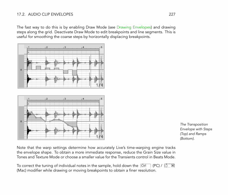
17.2. AUDIO CLIP ENVELOPES 227
The fast way to do this is by enabling Draw Mode (see Drawing Envelopes) and drawingsteps along the grid. Deactivate Draw Mode to edit breakpoints and line segments. This isuseful for smoothing the coarse steps by horizontally displacing breakpoints.
The TranspositionEnvelope with Steps(Top) and Ramps(Bottom).
Note that the warp settings determine how accurately Live's time-warping engine tracksthe envelope shape. To obtain a more immediate response, reduce the Grain Size value inTones and Texture Mode or choose a smaller value for the Transients control in Beats Mode.
To correct the tuning of individual notes in the sample, hold down the Ctrl (PC) /(Mac) modi�er while drawing or moving breakpoints to obtain a �ner resolution.
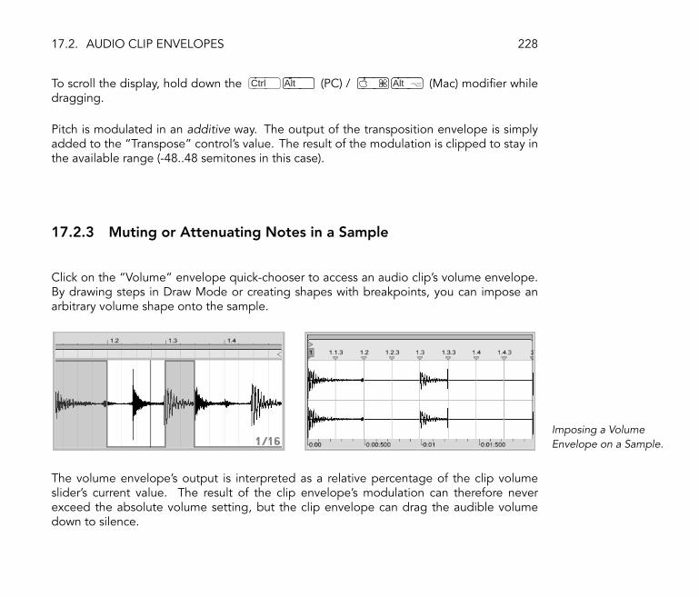
17.2. AUDIO CLIP ENVELOPES 228
To scroll the display, hold down the Ctrl Alt (PC) / Alt (Mac) modi�er whiledragging.
Pitch is modulated in an additive way. The output of the transposition envelope is simplyadded to the �Transpose� control's value. The result of the modulation is clipped to stay inthe available range (-48..48 semitones in this case).
17.2.3 Muting or Attenuating Notes in a Sample
Click on the �Volume� envelope quick-chooser to access an audio clip's volume envelope.By drawing steps in Draw Mode or creating shapes with breakpoints, you can impose anarbitrary volume shape onto the sample.
Imposing a VolumeEnvelope on a Sample.
The volume envelope's output is interpreted as a relative percentage of the clip volumeslider's current value. The result of the clip envelope's modulation can therefore neverexceed the absolute volume setting, but the clip envelope can drag the audible volumedown to silence.

17.2. AUDIO CLIP ENVELOPES 229
17.2.4 Scrambling Beats
One very creative use of clip envelopes is to modulate the sample offset. Sample offsetmodulation makes the most sense for rhythmical samples, and is only available for clips thatare set up to run in the �Beats� Warp Mode.
Try sample offset modulation with a one-bar drum loop: Make sure �Beats� Mode is chosen;in the Envelopes box, choose �Clip� from the Device chooser and �Sample Offset� from theControl chooser. The Envelope Editor appears with a vertical grid overlay. In envelope DrawMode (see Drawing Envelopes), set steps to non-zero values to hear the loop scrambled.What is going on?
Imagine the audio is read out by a tape head, the position of which is modulated by theenvelope. The higher a value the envelope delivers, the farther away the tape head is fromits center position. Positive envelope values move the head towards the �future,� negativevalues move it towards the �past.� Fortunately, Live performs the modulation in beats ratherthan centimeters: A vertical grid line is worth a sixteenth note of offset and the modulationcan reach from plus eight sixteenths to minus eight sixteenths.
Sample offset modulation is the tool of choice for quickly creating interesting variations ofbeat loops. We discourage using this technique for �analytical� cut-and-splice tasks; theyare much easier to perform using Live's Arrangement View, and the results can easily beconsolidated into new clips (see Consolidating Clips).

17.2. AUDIO CLIP ENVELOPES 230
Repeating Steps andSlowing Time with theSample Offset Envelope.
Some sample offset envelope gestures have a characteristic effect: a downward �escalator�shape, for instance, effectively repeats the step at the envelope's beginning. Similarly, asmooth ramp with a downwards slope is slowing time and can create nice slurring effectswhen the slope is not quite exactly 45 degrees; try this with a 1/32 Transients setting.
17.2.5 Using Clips as Templates
As you are making creative use of clip envelopes, the clips containing them develop a lifeof their own, independent of the original sample. You might wonder at a point: What doesthis clip sound like with a different sample? This is easy to �nd out by selecting the clipso that it is displayed in the Clip View and dragging the desired sample from one of theFile Browsers, or the Session or Arrangement View, onto the Clip View. All clip settings,including the envelopes, will remain unaltered; only the sample will be replaced.
Notice this procedure affects only the selected clip, whereas replacing a sample with theClip View's Replace button (see Replacing the Clip's Sample) will affect all clips using thatsample.

17.3. MIXER AND DEVICE CLIP ENVELOPES 231
17.3 Mixer and Device Clip Envelopes
Clip envelopes can be used to modulate mixer and device controls. Since mixer and devicecontrols can also be controlled by the Arrangement's automation envelopes (see Drawingand Editing Automation), this is a potential source of confusion. However, clip envelopesdiffer from automation envelopes in one important way: Whereas automation envelopesde�ne the value of a control at any given point in time, clip envelopes can only in�uencethis de�ned value. This difference allows the two types of envelopes to work together inharmony when controlling the same parameter.
Imagine that you have recorded volume automation for an audio clip so that it graduallyfades out over four bars. What happens to your fade-out when you create a clip envelopethat gradually increases the mixer volume over four bars? At �rst, your fade-out will becomea crescendo, as the clip envelope gradually increases the volume within the range allowedby the automation envelope. But, once the decreasing automated value meets with theincreasing clip envelope value, the fade-out will begin, as automation forces the absolutecontrol value (and the operable range of the clip envelope) down.
17.3.1 Modulating Mixer Volumes and Sends
Notice that there are actually two volume modulations: Clip Volume and Mixer Volume.The latter is a modulation for the mixer's gain stage and therefore affects the post-effectsignal. To prevent confusion, a small dot below the mixer's volume slider thumb indicatesthe actual, modulated volume setting.
Modulating the MixerVolume. The Little DotBelow the Volume SliderThumb Represents theModulated VolumeSetting.

17.3. MIXER AND DEVICE CLIP ENVELOPES 232
As you raise and lower the Volume slider, you can observe the dot following your movementin a relative fashion.
Modulating the track's Send controls is just as easy. Again, the modulation is a relativepercentage: The clip envelope cannot open the send further than the Send knob, but it canreduce the actual send value to minus in�nite dB. Modulating a Send. The
Send Knob's PositionRing Indicates theModulated Value.
17.3.2 Modulating Pan
The Pan envelope affects the mixer pan stage in a relative way: The pan knob's positiondetermines the intensity of the modulation. With the pan knob set to the center position,modulation by the clip envelope can reach from hard left to hard right; the modulationamount is automatically reduced as you move the pan knob towards the left or right. Whenthe pan knob is turned all the way to the left, for instance, the pan clip envelope has noeffect at all.
17.3.3 Modulating Device Controls
All devices in a clip's track are listed in the upper clip envelope Device chooser. Modulatingthe devices' controls works just as you would expect. When modulating device controls, itis important to keep the interaction of clip envelopes and device settings in mind: Unlike adevice preset (see Using the Live Devices), the clip envelope cannot de�ne the values forthe devices' controls, it can only change them relative to their current setting.
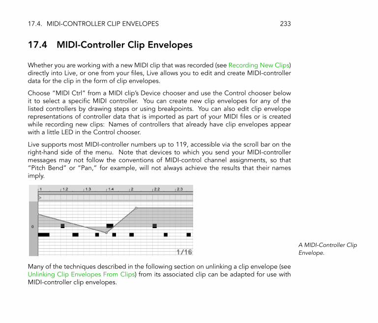
17.4. MIDI-CONTROLLER CLIP ENVELOPES 233
17.4 MIDI-Controller Clip Envelopes
Whether you are working with a new MIDI clip that was recorded (see Recording New Clips)directly into Live, or one from your �les, Live allows you to edit and create MIDI-controllerdata for the clip in the form of clip envelopes.
Choose �MIDI Ctrl� from a MIDI clip's Device chooser and use the Control chooser belowit to select a speci�c MIDI controller. You can create new clip envelopes for any of thelisted controllers by drawing steps or using breakpoints. You can also edit clip enveloperepresentations of controller data that is imported as part of your MIDI �les or is createdwhile recording new clips: Names of controllers that already have clip envelopes appearwith a little LED in the Control chooser.
Live supports most MIDI-controller numbers up to 119, accessible via the scroll bar on theright-hand side of the menu. Note that devices to which you send your MIDI-controllermessages may not follow the conventions of MIDI-control channel assignments, so that�Pitch Bend� or �Pan,� for example, will not always achieve the results that their namesimply.
A MIDI-Controller ClipEnvelope.
Many of the techniques described in the following section on unlinking a clip envelope (seeUnlinking Clip Envelopes From Clips) from its associated clip can be adapted for use withMIDI-controller clip envelopes.

17.5. UNLINKING CLIP ENVELOPES FROM CLIPS 234
17.5 Unlinking Clip Envelopes From Clips
A clip envelope can have its own local loop/region settings. The ability to unlink theenvelope from its clip creates an abundance of exciting creative options, some of which wewill present in the rest of this chapter.
17.5.1 Programming a Fade-Out for a Live Set
Let us start with a straightforward example. Suppose you are setting up a Live Set and wishto program a fade-out over eight bars to occur when a speci�c clip is launched � but all youhave is a one-bar loop.
1 3
42
Using a Clip Envelope toCreate a Fade-Out OverSeveral Repetitions of aLoop.
1. Choose the Clip Volume envelope, and unlink it from the sample.
The clip envelope's loop braces now appear colored to indicate this envelopenow has its own local loop/region settings. The loop/region controls in theEnvelopes box �come to life.�

17.5. UNLINKING CLIP ENVELOPES FROM CLIPS 235
2. Make sure the clip envelope's Loop switch is off. Notice the Sample box's Loopswitch is not affected. The sample will keep looping although the envelope isnow playing as a �one-shot.�
3. Type �8� into the leftmost envelope loop-length value box.
4. Zoom the envelope display out all the way by clicking on the Envelope's timeruler and dragging upwards.
5. Insert a breakpoint at the region end and drag it to the bottom (zero percent).
Now, as you play the clip, you can hear the one-bar loop fading out over eight bars.
Please note: toggling Linked Mode changes the envelope data. Toggling back and fortheffectively deletes the envelope data. To return to the previous state, please use the Editmenu's Undo command.
17.5.2 Creating Long Loops from Short Loops
Let us take this a step further. For a different part of your set, you would like to use thesame one-bar loop � because it sounds great � but its repetition bores you. You would liketo somehow turn it into a longer loop.
We depart from the clip we just set up to fade out over eight bars. Activate the clip volumeenvelope's Loop switch. Now, as you play the clip, you can hear the eight-bar fade-outrepeating. You can draw or edit any envelope to superimpose onto the sample loop. This,of course, not only works for volume but for any other control as well; how about a �ltersweep every four bars?
Note that you can create as much time as needed in the Envelope Editor, either by draggingthe loop braces beyond the view limit, or by entering values into the numeric region/loopcontrols.

17.5. UNLINKING CLIP ENVELOPES FROM CLIPS 236
You can choose an arbitrary loop length for each envelope, including odd lengths like 3.2.1.It is not hard to imagine great complexity (and confusion!) arising from several odd-lengthenvelopes in one clip.
The Sample (Left) andEnvelope (Right) StartMarker.
To keep this complexity under control, it is important to have a common point of reference.The start marker identi�es the point where sample or envelope playback depart from whenthe clip starts.
Note that the start/end markers and loop brace are subject to quantization by the zoom-adaptive grid (see Using the Editing Grid), as is envelope drawing (see Drawing Envelopes).
17.5.3 Imposing Rhythm Patterns onto Samples
So far, we have been talking about imposing long envelopes onto small loops. You canalso think of interesting applications that work the other way around. Consider a sampleof a song that is several minutes long. This sample could be played by a clip with a one-bar volume envelope loop. The volume envelope loop now works as a pattern that isrepeatedly �punching� holes into the music so as to, perhaps, remove every third beat. Youcan certainly think of other parameters that such a pattern could modulate in interestingways.

17.5. UNLINKING CLIP ENVELOPES FROM CLIPS 237
17.5.4 Clip Envelopes as LFOs
If you are into sound synthesis, you may want to think of a clip envelope with a local loopas an LFO. This LFO is running in sync with the project tempo, but it is also possible to setup a loop period odd enough to render the envelope unsynchronized. By hiding the grid(see Using the Editing Grid), you can adjust the clip envelope loop start and end pointscompletely independent of meter grid.

Chapter 18
Live Audio Effect Reference
Live comes with a selection of custom-designed, built-in audio effects. The �Working withInstruments and Effects� chapter (see Working with Instruments and Effects) explains thebasics of using effects in Live.
238

18.1. AUTO FILTER 239
18.1 Auto Filter
The Auto Filter Effect.
The Auto Filter effect provides classic analog �lter emulation. It can be modulated by anenvelope follower and/or an LFO to create moving �lter effects.
There are four different �lter types: low-pass, high-pass, band-pass and notch. For eachtype, the X-Y controller adjusts frequency (to adjust, click and drag on the X-axis) and Q(also called resonance; to adjust, click and drag on the Y-axis). You can also click on the Freqand Q numeric displays and type in exact values.
Low Q values create a broad �lter curve, while higher values introduce a narrow, resonantpeak to the sound. With band-pass �ltering, Q sets the bandwidth of the passed signal.
The Quantize Beat control applies quantized modulation to the �lter frequency. With Quan-tize Beat off, frequency modulation follows the control source. Turning this feature onupdates the �lter modulation rhythmically with �stepped� changes that track the mastertempo. The numbered buttons represent 16th notes, so, for example, selecting �4� as abeat value produces a modulation change once per beat.
The Envelope section controls how the envelope modulation affects the �lter frequency.The Amount control de�nes the extent to which the envelope affects the �lter frequency,

18.1. AUTO FILTER 240
while the Attack control sets how the envelope responds to rising input signals. Low Attackvalues cause a fast response to input levels; high values integrate any changes gradually,creating a looser, slower response. Think of it as adding inertia to the response.
Lower Release values cause the envelope to respond more quickly to falling input signals.Higher values extend the envelope's decay.
The Auto Filter also contains a Low Frequency Oscillator to modulate �lter frequency in aperiodic fashion. The respective Amount control sets how much the LFO affects the �lter.
The Rate control speci�es the LFO speed. It can be set in terms of hertz, or synced to theproject tempo and set in terms of meter subdivisions. The second option allows for creatingcontrolled rhythmic �ltering.
Available LFO waveform shapes are sine (creates smooth modulations with rounded peaksand valleys), square, triangle, sawtooth up, sawtooth down, and sample and hold (generatesrandom positive and negative modulation values) in mono and stereo.
There are two LFOs, one for each stereo channel. The Phase and Offset controls de�ne therelationship between these two LFOs.
Phase keeps both LFOs at the same frequency, but can set the two LFO waveforms �out ofphase� with each other, creating stereo movement. Set to �180�, the LFO outputs are 180degrees apart, so that when one LFO reaches its peak, the other is at its minimum.
Spin detunes the two LFO speeds relative to each other. Each stereo channel is modulatedat a different frequency, as determined by the Spin amount.
For sample and hold, the Phase and Spin controls are not relevant and do not affect thesound. Instead, the Auto Filter offers two kinds of sample and hold: The upper sample andhold type available in the chooser provides independent random modulation generators forthe left and right channels (stereo), while the lower one modulates both channels with thesame signal (mono).

18.2. AUTO PAN 241
18.2 Auto Pan
The Auto Pan Effect.
Auto Pan offers LFO-driven manipulation of amplitude and panning for creating automaticpanning, tremolo and amplitude modulation, and beat-synchronized chopping effects.
Auto Pan's LFOs modulate the amplitude of the left and right stereo channels with sine,triangle, sawtooth down or random waveforms.
The Shape control pushes the waveform to its upper and lower limits, �hardening� its shape.The waveform can be set to �Normal� or �Invert� (use �Invert� to, for example, create thesaw up waveform from the saw down waveform).
Auto Pan's LFO speed is controlled with the Rate control, which can be set in terms of hertz.Rate can also be synced with the project tempo and set in meter subdivisions (e.g., sixteenthnotes).
Though both LFOs run at the same frequency, the Phase control lends the sound stereomovement by offsetting their waveforms relative to each other. Set this to �180�, and theLFOs will be perfectly out of phase (180 degrees apart), so that when one reaches its peak,the other is at its minimum. Phase is particularly effective for creating vibrato effects.
The Offset control shifts the start point of each LFO along its waveform.
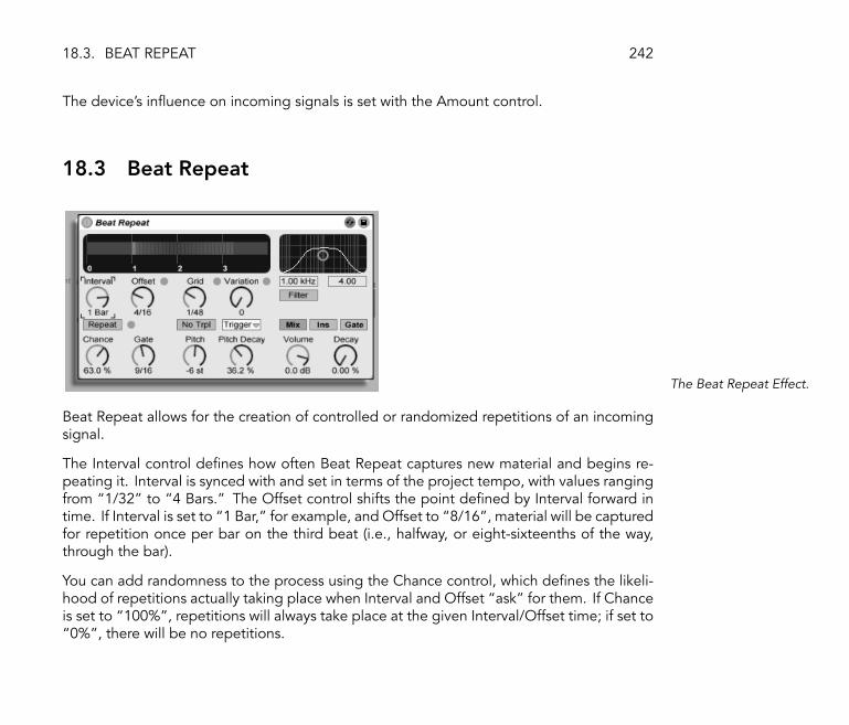
18.3. BEAT REPEAT 242
The device's in�uence on incoming signals is set with the Amount control.
18.3 Beat Repeat
The Beat Repeat Effect.
Beat Repeat allows for the creation of controlled or randomized repetitions of an incomingsignal.
The Interval control de�nes how often Beat Repeat captures new material and begins re-peating it. Interval is synced with and set in terms of the project tempo, with values rangingfrom �1/32� to �4 Bars.� The Offset control shifts the point de�ned by Interval forward intime. If Interval is set to �1 Bar,� for example, and Offset to �8/16�, material will be capturedfor repetition once per bar on the third beat (i.e., halfway, or eight-sixteenths of the way,through the bar).
You can add randomness to the process using the Chance control, which de�nes the likeli-hood of repetitions actually taking place when Interval and Offset �ask� for them. If Chanceis set to �100%�, repetitions will always take place at the given Interval/Offset time; if set to�0%�, there will be no repetitions.
18.3. BEAT REPEAT 243
Gate de�nes the total length of all repetitions in sixteenth notes. If Gate is set to �4/16�,the repetitions will occur over the period of one beat, starting at the position de�ned byInterval and Offset.
Activating the Repeat button bypasses all of the above controls, immediately capturingmaterial and repeating it until deactivated.
The Grid control de�nes the grid size � the size of each repeated slice. If set to �1/16�, aslice the size of one sixteenth note will be captured and repeated for the given Gate length(or until Repeat is deactivated). Large grid values create ryhthmic loops, while small valuescreate sonic artifacts. The No Triplets button sets grid division as binary.
Grid size can be changed randomly using the Variation control. If Variation is set to �0�,grid size is �xed. But when Variation is set to higher values, the grid �uctuates considerablyaround the set Grid value. Variation has several different modes, available in the chooserbelow: Trigger creates variations of the grid when repetitions are triggered; 1/4, 1/8 and1/16 trigger variations in regular intervals; and Auto forces Beat Repeat to apply a newrandom variation after each repetition � the most complex form of grid variation in BeatRepeat (especially if triplets are also allowed).
Beat Repeat's repetitions can be pitched down for special sonic effects. Pitch is adjustedthrough resampling in Beat Repeat, lengthening segments to pitch them down without againcompressing them to adjust for the length change. This means that the rythmical structurecan become quite ambiguous with higher Pitch values. The Pitch Decay control tapers thepitch curve, making each repeated slice play lower than the previous one. Warning: This isthe most obscure parameter of Beat Repeat.
Beat Repeat includes a combined low-pass and high-pass �lter for de�ning the passedfrequency range of the device. You can turn the �lter on and off, and set the centerfrequency and width of the passed frequency band, using the respective controls.
The original signal (which was received at Beat Repeat's input) is mixed with Beat Repeat'srepetitions according to one of three mix modes: Mix allows the origial signal to passthrough the device and have repetitions added to it; Insert mutes the original signal when
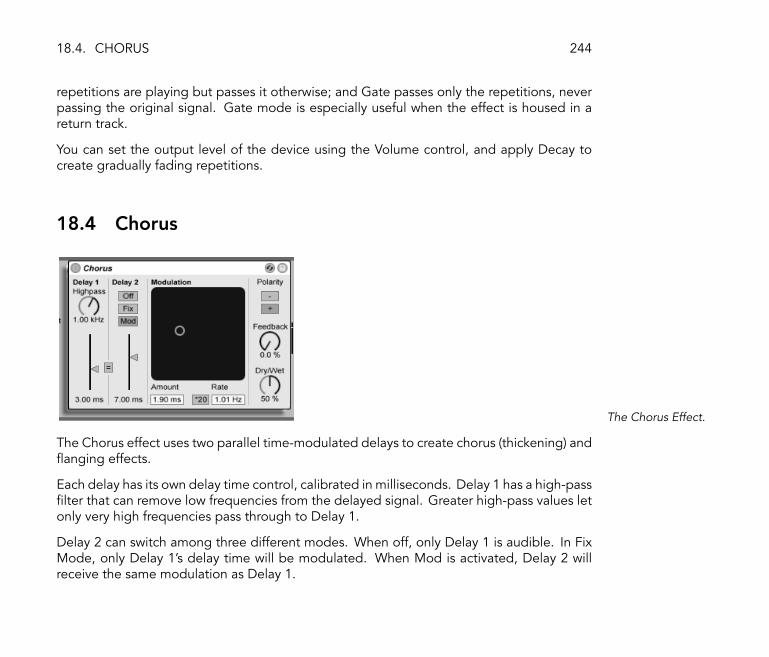
18.4. CHORUS 244
repetitions are playing but passes it otherwise; and Gate passes only the repetitions, neverpassing the original signal. Gate mode is especially useful when the effect is housed in areturn track.
You can set the output level of the device using the Volume control, and apply Decay tocreate gradually fading repetitions.
18.4 Chorus
The Chorus Effect.
The Chorus effect uses two parallel time-modulated delays to create chorus (thickening) and�anging effects.
Each delay has its own delay time control, calibrated in milliseconds. Delay 1 has a high-pass�lter that can remove low frequencies from the delayed signal. Greater high-pass values letonly very high frequencies pass through to Delay 1.
Delay 2 can switch among three different modes. When off, only Delay 1 is audible. In FixMode, only Delay 1's delay time will be modulated. When Mod is activated, Delay 2 willreceive the same modulation as Delay 1.

18.4. CHORUS 245
To set both delay lines to Delay 1's delay time, turn on the link button (�= �). This is especiallyuseful if you want to change both delays with a single gesture.
The Modulation X-Y controller can impart �motion� to the sounds. To change the modula-tion rate for the delay times, click and drag along the horizontal axis. To change the amountof modulation, click and drag along the vertical axis.
You can also make changes by entering parameter values in the Amount and Rate �elds be-low the X-Y controller. The Amount value is in milliseconds, while the modulation frequencyrate is in Hertz.
Clicking the *20 switch multiplies the modulation frequency by 20 to achieve more extremesounds.
The Feedback control determines how much of the output signal feeds back into the input,while the Polarity switch sets (surprise!) the polarity. Polarity changes have the most effectwith high amounts of feedback and short delay times.
The Dry/Wet control adjusts the balance between the processed and dry signals. Set it towet only if using the Chorus in a return channel.

18.5. COMPRESSOR I 246
18.5 Compressor I
The Compressor I Effect.
A Compressor reduces gain for signals above a user-settable threshold. Compression re-duces the levels of peaks, opening up more headroom and allowing the overall signal levelto be turned up. This gives the signal a higher average level, resulting in a sound that issubjectively louder and �punchier� than an uncompressed signal.
The two most important parameters are the Threshold and the compression Ratio:
The Threshold slider sets where compression begins. Signals below the threshold are notprocessed. Signals above the threshold are attenuated by an amount speci�ed by the Ratioparameter, which sets the ratio between the input and output signal. For example, with acompression ratio of 3:1, if a signal above the threshold increases by 3 dB, the compressoroutput will increase by only 1 dB. If a signal above the threshold increases by 6 dB, then theoutput will increase by only 2 dB.
The red gain-reduction meter shows how much the gain is being reduced at any givenmoment. The more reduction, the more audible the effect; a gain reduction above 6 dBor so might produce the desired loudness, but signi�cantly alters the sound and is easilycapable of destroying its dynamic structure. This is something that cannot be undone inlater production steps. Keep this in mind especially when using a compressor, limiter or
18.5. COMPRESSOR I 247
sound loudness-maximizing tool in the master channel. Less is often more here.
Because compression reduces the volume of loud signals and opens up headroom, you canuse the Out(put) slider so that the peaks once again hit the maximum available headroom.The Output meter shows the output signal's level.
A second set of two essential parameters de�nes how fast a compressor reacts to input-levelchanges: Attack time and Release time.
Attack de�nes how long it takes to reach maximum compression once a signal exceedsthe threshold, while Release sets how long it takes for the compressor to return to normaloperation after the signal falls below the threshold.
A slight amount of attack time (5�10 ms) allows peaks to come through unprocessed,which helps preserve dynamics. If these peaks cause overloads, you can try shortening theattack time, but extremely short times take the �life� out of the signal, and may lead to aslight �buzziness� caused by distortion. Short release times can cause �pumping� as thecompressor tries to �gure out whether to compress or not; while generally considered anundesirable effect, some engineers use it on full drum kits to give unusual �sucking� effects.

18.6. COMPRESSOR II 248
18.6 Compressor II
The Compressor IIEffect.
Compressor II is a state of the art compression unit � the tool of choice for a wide range ofdynamic processing applications including limiting and loudness maximization. CompressorII's design is a lot more sophisticated and capable than Compressor I's. It includes frequency-selective compression using a sidechain EQ, variable look-ahead times and two responsemodes, Peak and RMS. Compressor I is still a valuable sound design tool in spite of, or ratherbecause of, its simplicity and roughness, which can add interesting �avors to your sounds.
A compressor can only react to an input signal once it occurs. Since it also needs to applyan attack/release envelope, the compression is always a bit too late. A digital compressorcan solve this problem by simply delaying the input signal a little bit. Compressor II offersthree different predelay times: zero ms, one ms and ten ms. The results may sound prettydifferent depending on this setting. Keep in mind that using ten ms of predelay makes theoutput appear signi�cantly later. You may have to delay other tracks with a Simple Delay inorder to stay in sync.
Compressor II can either react to short peaks within a signal or to something that is morerelated to how people perceive loudness. The parameter for this is the �Peak/RMS� switch.If you intend to use Compressor II as a limiter in the master section, �Peak� is probably

18.6. COMPRESSOR II 249
better since it reacts more to the actual signal level, while �RMS� is usually more musical.But as always if it comes to compression, trust your ears and not the meter!
The most exotic feature of Compressor II is the sidechain EQ. The �sidechain� is the part ofthe signal that is used to control the compressor. Normally the sidechain signal is the sameas the input signal. However, it can make sense to apply some �ltering here. Imagine a bassdrum, a snare and some chords in the background. The bass drum has a pretty high leveland it will normally determine how the compressor reacts. If you now turn the side chain EQon and set its Frequency to 100 Hz and the Gain to -15 dB, the bass drum will not in�uencethe compression anymore and the behavior of the compressor will be very different. Youcould also set the Frequency to around 1 kHz and turn up the gain to make the compressormore responsive to the snare. Since the EQ is only in the sidechain and not part of thenormal signal path, it will not change the sound of the input signal. It only changes how thecompressor reacts to different frequencies of the input.
Unlike Compressor I, Compressor II has a built-in compensation stage that counteracts thegain loss due to the compression and makes it much easier to adjust the other parameters.
Careful adjustment of attack and release times is essential when it comes to compression ofrhythmical sources. If you are not used to working with compressors, play a drum loop andspend some time adjusting Attack, Release, Threshold and Gain. It can be very exciting!

18.7. EQ THREE 250
18.7 EQ Three
The EQ Three Effect.
If you have ever used a good DJ mixer you will know what this is: An EQ that allows you toadjust the level of low, mid and high frequencies independently.
Each band can be adjusted from -in�nite dB to +6 dB using the gain controls. This meansthat you can completely remove, for example, the bass drum or bassline of a track, whileleaving the other frequencies untouched.
You can also turn on or off each band using the On/Off buttons located under the gaincontrols. These buttons are especially handy if assigned to computer keys...
EQ Three gives you visual con�rmation of the presence of a signal in each frequency bandusing three green LEDs. Even if a band is turned off, you can see if there is something goingon in it. The internal threshold for the LEDs is set to -24 dB.
The frequency range of each band is de�ned via two crossover controls: FreqLo and FreqHi.If FreqLo is set to 500 Hz and FreqHi to 2000 Hz, then the low band goes from 0 hz to 500Hz, the mid band from 500 Hz to 2000 Hz and the high band from 2000 Hz up to what everyour soundcard or sample rate supports.
A very important control is the 24 dB / 48 dB switch. It de�nes how sharp the �lters are
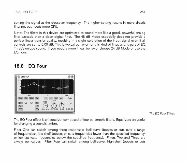
18.8. EQ FOUR 251
cutting the signal at the crossover frequency. The higher setting results in more drastic�ltering, but needs more CPU.
Note: The �lters in this device are optimized to sound more like a good, powerful analog�lter cascade than a clean digital �lter. The 48 dB Mode especially does not provide aperfect linear transfer quality, resulting in a slight coloration of the input signal even if allcontrols are set to 0.00 dB. This is typical behavior for this kind of �lter, and is part of EQThree's unique sound. If you need a more linear behavior choose 24 dB Mode or use theEQ Four.
18.8 EQ Four
The EQ Four Effect.
The EQ Four effect is an equalizer composed of four parametric �lters. Equalizers are usefulfor changing a sound's timbre.
Filter One can switch among three responses: bell-curve (boosts or cuts over a rangeof frequencies), low-shelf (boosts or cuts frequencies lower than the speci�ed frequency)or low-cut (cuts frequencies below the speci�ed frequency). Filters Two and Three arealways bell-curves. Filter Four can switch among bell-curve, high-shelf (boosts or cuts

18.9. EROSION 252
frequencies higher than the speci�ed frequency) or high-cut (cuts frequencies above thespeci�ed frequency) modes. Each �lter band can be turned on or off independently. Turnoff bands that aren't in use to save CPU power.
To edit the �lter curve, click and drag on one of the �lter dots in the XY View. Horizontalmovement changes the �lter frequency, while vertical movement adjusts the �lter band'sgain. To adjust the �lter Q (also called resonance or bandwidth), hold down the Alt (PC)/ Alt (Mac) modi�er while dragging the mouse.
You can also use the numbered �lter selector buttons to select a band for editing, then editparameter values with the Freq, Gain and Q dials (and/or type values into the number �eldsbelow each dial).
To achieve really drastic �ltering effects, assign the same parameters to two or more �lters,or use more than one EQ Four.
As boosting will increase levels and cutting will decrease levels, use the Gain slider tooptimize the output level for maximum level consistent with minimum distortion.
18.9 Erosion
The Erosion Effect.

18.10. FILTER DELAY 253
The Erosion effect degrades the input signal by modulating a short delay with �ltered noiseor a sine wave. This adds noisy artifacts or aliasing/downsampling-like distortions that soundvery �digital.�
To change the sine wave frequency or noise band center frequency, click and drag alongthe X-axis in the XY �eld. The Y-axis controls the modulation amount. If you hold down theAlt (PC) / Alt (Mac) modi�er key while clicking in the XY �eld, the Y-axis controls the
noise bandwidth.
The Frequency control determines the color, or quality, of the distortion. If the Mode controlis set to Noise, this works in conjunction with the Width control, which de�nes the noisebandwidth. Lower values lead to more selective distortion frequencies, while higher valuesaffect the entire input signal. Width has no effect in Sine Mode.
Noise and Sine use a single modulation generator. However, Wide Noise has independentnoise generators for the left and right channels, which creates a subtle stereo enhancement.
18.10 Filter Delay
The Filter Delay Effect.

18.10. FILTER DELAY 254
The Filter Delay provides three independent delay lines, each preceded by linked low-passand high-pass �lters. This allows applying delay to only certain input signal frequencies, asdetermined by the �lter settings. The feedback from each of the three delays is also routedback through the �lters.
Each of the three delays can be switched on and off independently. The Filter Delay plug-inassigns delay 1 to the input signal's left channel, delay 2 to the left and right channels anddelay 3 to the right channel. The Pan controls at the right can override the delay channels'outputs; otherwise each delay outputs on the channel from which it derives its input.
Each delay channel's �lter has an associated On switch, located to the left of each XYcontroller. The XY controllers adjust the low- and high-pass �lters simultaneously for eachdelay. To edit �lter bandwidth, click and drag on the vertical axis; click and drag on thehorizontal axis to set the �lter band's frequency.
To refer delay time to the master tempo, activate the Sync switch, which allows using theDelay time beat division chooser. The numbered switches represent time delay in 16thnotes. For example, selecting �4� delays the signal by four 16th notes, which equals onebeat (a quarter note) of delay. With Sync Mode active, changing the Delay Time �eldpercentage value shortens and extends delay times by fractional amounts, thus producingthe �swing� type of timing effect found in drum machines.
If the Sync switch is off, the delay time reverts to milliseconds. In this case, to edit the delaytime, click and drag up or down in the Delay Time �eld, or click in the �eld and type in avalue.
Feedback controls how much of the output signal returns to the delay line input. Very highvalues can lead to runaway feedback and produce a loud oscillation � watch your ears andspeakers if you decide to check out extreme feedback settings!
Each delay channel has its own volume control, which can be turned up to +12 dB tocompensate for drastic �ltering at the input.
The Dry control adjusts the unprocessed signal level. Set it to minimum if using the Delay

18.11. FLANGER 255
in a return channel.
18.11 Flanger
The Flanger Effect.
Flanger uses two parallel time-modulated delays to create �anging effects.
Flanger's delays can be adjusted with the Delay Time control. The Feedback control sendspart of the output signal back through the device input, while the Polarity switch (�+� or�-�) sets the polarity. Delay Time and Feedback can be changed simultaneously using theeffect's X-Y controller.
Periodic control of delay time is possible using the envelope section. You can increase ordecrease the envelope amount (or invert its shape with negative values), and then use theAttack and Release controls to de�ne envelope shape.
Flanger contains two LFOs to modulate delay time for the left and right stereo channels.LFOs can have six possible waveform shapes: sine, square, triangle, sawtooth up, sawtoothdown and random. The extent of LFO in�uence on the delays is set with the Amount control.
Flanger's LFO speed is controlled with the Rate control, which can be set in terms of hertz.
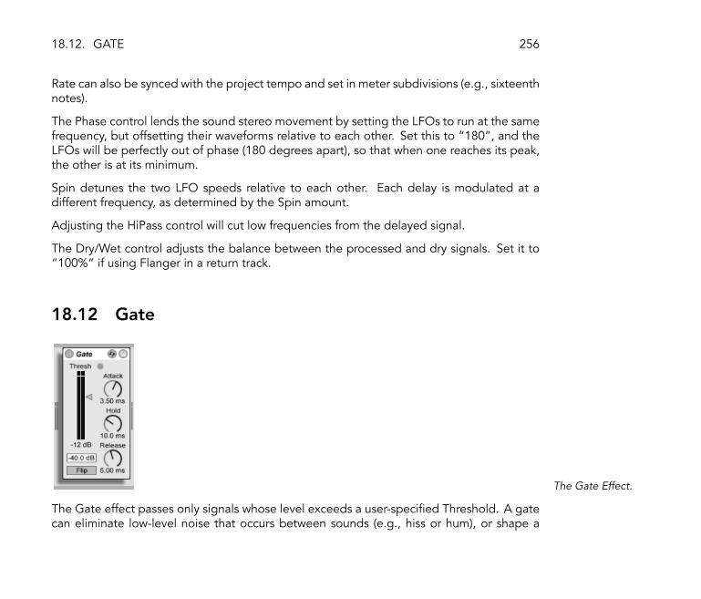
18.12. GATE 256
Rate can also be synced with the project tempo and set in meter subdivisions (e.g., sixteenthnotes).
The Phase control lends the sound stereo movement by setting the LFOs to run at the samefrequency, but offsetting their waveforms relative to each other. Set this to �180�, and theLFOs will be perfectly out of phase (180 degrees apart), so that when one reaches its peak,the other is at its minimum.
Spin detunes the two LFO speeds relative to each other. Each delay is modulated at adifferent frequency, as determined by the Spin amount.
Adjusting the HiPass control will cut low frequencies from the delayed signal.
The Dry/Wet control adjusts the balance between the processed and dry signals. Set it to�100%� if using Flanger in a return track.
18.12 Gate
The Gate Effect.
The Gate effect passes only signals whose level exceeds a user-speci�ed Threshold. A gatecan eliminate low-level noise that occurs between sounds (e.g., hiss or hum), or shape a

18.12. GATE 257
sound by turning up the threshold to where it cuts off reverb or delay tails or truncates aninstrument's natural decay.
The Threshold slider sets the gate's sensitivity. If the gate is open and passing signal (i.e.,the signal exceeds the gate threshold), the green LED lights.
The Floor parameter located above the threshold fader can allow attenuating signals belowthe threshold rather than just cutting them off. If set to -inf dB, a closed gate will mute theinput signal. A setting of 0.00 dB means that even if the gate is closed, there is no effecton the signal. Settings in between these two extremes attenuate the input to a greater orlesser degree when the gate is closed.
The Attack time determines how long it takes for the gate to switch from closed to openwhen a signal goes from below to above the threshold. Very short attack times can producesharp clicking sounds, while long times soften the sound's attack.
When the signal goes from above to below the threshold, the Hold time kicks in. (Noteto tech heads: the gate has hysteresis, so the release occurs about 3 dB lower than thethreshold.) After the hold time expires, the gate closes over a period of time set by theRelease parameter.

18.13. GRAIN DELAY 258
18.13 Grain Delay
The Grain Delay Effect.
The Grain Delay effect slices the input signal into tiny particles (called �grains�) that are thenindividually delayed and can also have different pitches compared to the original signalsource. Randomizing pitch and delay time can create complex masses of sound and rhythmthat seem to bear little relationship to the source. This can be very useful in creating newsounds and textures, as well as getting rid of unwelcome house guests, or terrifying smallpets (just kidding!).
To refer delay time to the master tempo, activate the Sync switch, which allows using theDelay Time beat division chooser. The numbered switches represent time delay in 16thnotes. For example, selecting �4� delays the signal by four 16th notes, which equals onebeat (a quarter note) of delay. With Sync Mode active, changing the Delay Time �eldpercentage value shortens and extends delay times by fractional amounts, thus producingthe �swing� type of timing effect.
If the Sync switch is off, the delay time reverts to milliseconds. In this case, to edit the delaytime, click and drag up or down in the Delay Time �eld, or click in the �eld and type in avalue.
You can route each parameter to the XY controller's horizontal or vertical axis. To assign a

18.13. GRAIN DELAY 259
parameter to the X-axis, choose it from the parameter row below the controller. To assign aparameter to the Y-axis, use the parameter row on the left side.
The Feedback parameter sets how much of the output signal returns to the delay line input.Very high values can lead to runaway feedback and produce a loud oscillation � watch yourears and speakers if you decide to check out extreme feedback settings!
You can transpose the grain pitch with the Pitch parameter, which acts much like a crudepitch shifter.
The Spray control adds random delay time changes. Low values smear the signal acrosstime, which adds �noisiness� to the sound. High Spray values completely break down thestructure of the source signal, introducing varying degrees of rhythmical chaos. This is therecommended setting for anarchists.
The Random Pitch control adds random variations to each grain's pitch. Low values createa sort of mutant chorusing effect, while high values can make the original source pitchcompletely unintelligible. This parameter can interact with the main Pitch control, thusallowing degrees of stability and instability in a sound's pitch structure.
The size and duration of each grain is a function of the Frequency parameter. The sound ofPitch and Spray depends very much on this parameter.
Grain Delay now also has a dry/wet control; it can be routed to the vertical axis of the XYcontroller.

18.14. PHASER 260
18.14 Phaser
The Phaser Effect.
Phaser uses a series of all-pass �lters to create a phase shift in the frequency spectrum of asound.
The Poles control creates notches in the frequency spectrum. The Feedback control canthen be used to invert the waveform and convert these notches into peaks (or poles). Filtercutoff frequency is changed with the Frequency control, which can be adjusted in tandemwith Feedback using the effect's X-Y controller.
The device has two modes, Space and Earth, for changing the spacing of notches along thespectrum, and hence the �color� of the sound. This effect can be further adjusted with theColor control.
Periodic control of the �lter frequency is possible using the envelope section. You canincrease or decrease the envelope amount (or invert its shape with negative values), andthen use the Attack and Release controls to de�ne envelope shape.
Phaser contains two LFOs to modulate �lter frequency for the left and right stereo channels.LFOs can have six possible waveform shapes: sine, square, triangle, sawtooth up, sawtoothdown and random. The extent of LFO in�uence on the �lter frequency is set with the

18.15. PING PONG DELAY 261
Amount control.
LFO speed is controlled with the Rate control, which can be set in terms of hertz. Rate canalso be synced with the project tempo and set in meter subdivisions (e.g., sixteenth notes).
The Phase control lends the sound stereo movement by setting the LFOs to run at the samefrequency, but offsetting their waveforms relative to each other. Set this to �180�, and theLFOs will be perfectly out of phase (180 degrees apart), so that when one reaches its peak,the other is at its minimum.
Spin detunes the two LFO speeds relative to each other. Each �lter frequency is thenmodulated using a different LFO frequency, as determined by the Spin amount.
The Dry/Wet control adjusts the balance between the processed and dry signals. Set it to�100%� if using Phaser in a return track.
18.15 Ping Pong Delay
The Ping Pong DelayEffect.
The Ping Pong Delay effect uses a single tapped delay line to create a delay that jumpsfrom the left to the right output.

18.15. PING PONG DELAY 262
The delay is preceded by a low- and high-pass �lter that can be controlled with an XYcontroller. To de�ne the �lter bandwidth, click and drag on the vertical axis. To set theposition of the frequency band, click and drag on the horizontal axis.
To refer delay time to the master tempo, activate the Sync switch, which allows using theDelay Time beat division chooser. The numbered switches represent time delay in 16thnotes. For example, selecting �4� delays the signal by four 16th notes, which equals onebeat (a quarter note) of delay. This delay time represents the time it takes for the inputsignal to appear at the left channel. The delay time between the input and the right channelis twice as long.
If the Sync switch is off, the delay time reverts to milliseconds. In this case, to edit the delaytime, click and drag up or down in the time �eld, or click in the �eld and type in a value.
The Feedback parameter controls how much of the right channel output signal returns tothe delay line input. The feedback loop also includes a �lter that can color the feedbacksound, thus producing different timbres with successive echoes.
The Dry/Wet control adjusts the balance between the processed and dry signals. Set it tofull wet if using the Ping Pong Delay in a return channel.

18.16. SATURATOR 263
18.16 Saturator
The Saturator Effect.
Saturator is a distortion effect that can add that missing dirt, punch or warmth to your sound.
Incoming signals are clipped to the Drive control's setting in dB. Signal clipping has severalmodes: Clip, Soft, Medium, Hard and Sine. In Clip mode, the signal is clipped completelyand immediately. Soft, Medium and Hard modes soften signal clipping to varying degrees.Sine mode can be used for special effects.
The meter in the display will show how much Saturator is in�uencing a signal.
Activating the Color button enables two �lters. The �rst of these, controlled with the Basecontrol, dictates how much the effect will be reduced or increased for very low frequencies.The second �lter, essentially an equalizer, is used for controlling higher frequencies. It isshaped with the Freq (cutoff frequency), Width and Depth controls.
The Output control reduces or increases the level at the device output. The signal at thedevice input can be ampli�ed using the Drive control.
The Dry/Wet control adjusts the balance between the processed and dry signals. Set it tofull wet if using the Saturator in a return channel.

18.17. SIMPLE DELAY 264
18.17 Simple Delay
The Simple Delay Effect.
The Simple Delay provides two independent delay lines, one for each channel (left andright).
To refer delay time to the master tempo, activate the Sync switch, which allows using theDelay Time beat division chooser. The numbered switches represent time delay in 16thnotes. For example, selecting �4� delays the signal by four 16th notes, which equals onebeat (a quarter note) of delay. If the Sync switch is off, the delay time reverts to milliseconds.In this case, to edit the delay time, click and drag up or down in the Delay Time �eld, orclick in the �eld and type in a value.
The Feedback parameter de�nes how much of each channel's output signal feeds back intothe delay lines' inputs. Internally there are two independent feedback loops, so a signal onthe left channel does not feed back into the right channel and vice versa.
The Dry/Wet control adjusts the balance between the processed and dry signals. Set it tofull wet if using the Simple Delay in a return channel.

18.18. VINYL DISTORTION 265
18.18 Vinyl Distortion
The Vinyl DistortionEffect.
The Vinyl Distortion effect emulates some of the typical distortions that occur on vinyl recordsduring playback. These distortions are caused by the geometric relationships between theneedle and the recorded groove. The effect also features a crackle generator for addingnoisy artifacts.
The Tracing Model section adds even harmonic distortion to the input signal. Adjust theamount of distortion with the Drive knob, or click and drag vertically in the Tracing Model XYwindow. To adjust the distortion's frequency or �color,� drag horizontally in the XY windowor double-click on the Freq �eld and type in a value. Holding the Alt (PC) / Alt
(Mac) modi�er while dragging vertically in the XY window changes the frequency band's Q(bandwidth).
The Pinch Effect section adds odd harmonics to the input signal. These distortions typicallyoccur 180 degrees out of phase, creating a richer stereo image. The Pinch Effect has thesame controls as the Tracing Model, but generates a rather different sound.
The Drive control increases or decreases the overall distortion amount created by both theTracing Model and Pinch.

18.19. REDUX 266
There are two distortion modes: soft and hard. The soft mode simulates the sound of a dubplate, while hard mode is more like that of a standard vinyl record.
The stereo/mono switch determines whether the Pinch distortion occurs in stereo or mono.Set it to stereo for realistic simulation of vinyl distortions.
The Crackle section adds noise to the signal, with noise density set by the Density control.The Volume control adjusts the amount of gain applied to the noise.
18.19 Redux
The Redux Effect.
Nostalgic for the famed low-resolution sound quality of the Ensoniq Mirage, Fairlight CMIor Commodore-64 computer? Redux returns us to the Dark Ages of digital by reducing asignal's sample rate and bit resolution.
The Downsample section has two parameters: �Downsample� and a downsample Modeswitch.
If the downsample dial is set to �1�, every input sample passes to the output and the signaldoes not change. If set to �2�, only every second sample will be processed, so the resultsounds a bit more �digital.� The higher the number, the lower the resulting sample rate,

18.20. RESONATORS 267
and the more �deconstructed� the sound. Downsampling is like applying a mosaic effectto an image: There's a loss of information and sharp edges occur between the blocks.
The Downsample Mode switch de�nes if the downsampling either interpolates over a smallerrange (�soft,� down to 20.0 samples) or does not interpolate over a larger range (�hard,�down to 200 samples).
Bit Reduction is similar, but while downsampling superimposes a grid in time, bit reductiondoes the same for amplitude.
If the Bit Reduction amplitude dial is set to 8, amplitude levels are quantized to 256 steps(8 bit resolution). If set to 1, the result is pretty brutal: Each sample contains either a fullpositive or full negative signal, with nothing in between.
Bit Reduction de�nes an input signal of 0dB as 16 bit. Signals above 0dB are clipped, andthe red overload LED will light up.
Turning off Bit Reduction results in modest CPU savings.
18.20 Resonators
The Resonators Effect.

18.20. RESONATORS 268
This device consists of �ve parallel resonators that superimpose a tonal character on theinput source. It can produce sounds resembling anything from plucked strings to vocoder-like effects. The resonators are tuned in semitones, providing a musical way of adjustingthem. The �rst resonator de�nes the root pitch and the four others are tuned relative to thispitch in musical intervals.
The input signal passes �rst through a �lter, and then into the resonators. There are fourinput �lter types to select from: low-pass, band-pass, high-pass and notch. The input �lterfrequency can be adjusted with the Frequency parameter.
The �rst resonator is fed with both the left and right input channels, while the second andfourth resonators are dedicated to the left channel, and the third and �fth to the rightchannel.
The Note parameter de�nes the root pitch of all the resonators ranging from C1 to C5.It can also be detuned in cents using the Fine parameter. The Decay parameter lets youadjust the amount of time it takes for the resonators to be silent after getting an input signal.The longer the decay time, the more tonal the result will be, similar to the behavior of anundamped piano string. As with a real string, the decay time depends on the pitch, so lownotes will last longer than higher ones. The Const switch holds the decay time constantregardless of the actual pitch.
Resonators provides two different resonation modes. Mode A provides a more realisticsounding resonation, while Mode B offers an effect that is especially interesting whenResonator I's Note parameter is set to lower pitches.
The brightness of the resulting sound can be adjusted using the Color control.
All of the resonators have an On/Off switch and a Gain control. A resonator that is turnedoff does not need CPU. Turning off the �rst resonator does not affect the other ones.
Resonators II through V follow the Note parameter de�ned in Resonator I, but they can eachbe individually transposed +/- 24 semitones using the Pitch controls and detuned in centsusing the Detune controls.
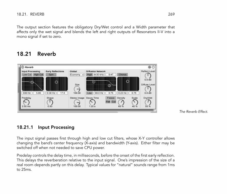
18.21. REVERB 269
The output section features the obligatory Dry/Wet control and a Width parameter thataffects only the wet signal and blends the left and right outputs of Resonators II-V into amono signal if set to zero.
18.21 Reverb
The Reverb Effect.
18.21.1 Input Processing
The input signal passes �rst through high and low cut �lters, whose X-Y controller allowschanging the band's center frequency (X-axis) and bandwidth (Y-axis). Either �lter may beswitched off when not needed to save CPU power.
Predelay controls the delay time, in milliseconds, before the onset of the �rst early re�ection.This delays the reverberation relative to the input signal. One's impression of the size of areal room depends partly on this delay. Typical values for �natural� sounds range from 1msto 25ms.

18.21. REVERB 270
18.21.2 Early Re�ections
These are the earliest echoes that you hear after they bounce off a room's walls, beforethe onset of the diffused reverberation �tail.� Their amplitude and distribution give animpression of the room's character.
The Shape control �sculpts� the prominence of the early re�ections, as well as their overlapwith the diffused sound. With small values, the re�ections decay more gradually and thediffused sound occurs sooner, leading to a larger overlap between these components. Withlarge values, the re�ections decay more rapidly and the diffused onset occurs later. Ahigher value can sometimes improve the source's intelligibility, while a lower value may givea smoother decay.
Spin applies modulation to the early re�ections. The 2-D control accesses the depth andfrequency of these modulations. A larger depth tends to provide a less-colored (morespectrally neutral) late diffusion response. If the modulation frequency is too high, dopplerfrequency shifting of the source sound will occur, along with surreal panning effects. Spinmay be turned off, using the associated switch, with modest CPU savings.
18.21.3 Global Settings
The Quality chooser controls the tradeoff between reverb quality and performance. Econ-omy mode uses minimal CPU resources, while First Class delivers the richest reverberation.
The Size parameter controls the �room's� volume. At one extreme, a very large size willlend a shifting, diffused delay effect to the reverb. The other extreme, a very small value,will give it a highly colored, metallic feel.
The Stereo Image control determines the width of the output's stereo image. At the highestsetting of 120 degrees, each ear receives a reverberant channel that is independent of theother (this is also a property of the diffusion in real rooms). The lowest setting mixes theoutput signal to mono.

18.21. REVERB 271
18.21.4 Diffusion Network
The Diffusion network creates the reverberant tail that follows the early re�ections. Thedecay time control adjusts the time required for this tail to drop to 1/1000th (-60 dB) of itsinitial amplitude.
High and low shelving �lters provide frequency-dependent reverberation decay. The high-frequency decay models the absorption of sound energy due to air, walls and other materialsin the room (people, carpeting and so forth). The low shelf provides a thinner decay. Each�lter may be turned off to save CPU consumption.
The Freeze control freezes the diffuse response of the input sound. When on, the reverber-ation will sustain almost endlessly. Cut modi�es Freeze by preventing the input signal fromadding to the frozen reverberation; when off, the input signal will contribute to the diffusedamplitude. Flat bypasses the high and low shelf �lters when freeze is on. If Flat is off, thefrozen reverberation will lose energy in the attenuated frequency bands, depending on thestate of the high and low shelving �lters.
The Echo Density and Scale parameters provide additional control over the diffusion's den-sity and coarseness, and, when the room size is extremely small, have a large impact on thecoloration contributed by the diffusion.
The Chorus section adds a little modulation and motion to the diffusion. Like the Spinsection, you can control the modulation frequency and amplitude, or turn it off.
18.21.5 Output
At the reverb output, you can adjust the effect's overall Dry/Wet mix, and vary the amplitudeof re�ections and diffusion with the Re�ect Level and Diffuse Level controls.

18.22. UTILITY 272
18.22 Utility
The Utility Effect.
Utility can perform some very useful tasks, especially in combination with other effects.
Most obvious is the Gain control, which allows adjusting the level of the input signal from-36 to +36 dB. The Gain control is located below the Mute button, which simply turns thesignal off if pressed.
Note: The active/mute controls of a track are always placed at the very end of the signalchain. However, since you can place Utility anywhere in a signal chain, you can use its mutefunction to cut the input of a delay line or reverb without turning off the output of thesedevices.
The Left/Right buttons allow further processing of only the left or right channel of a sample.If, for example, Left is turned on, the right channel is ignored and the left channel appearson both outputs. This is especially useful if you have a stereo �le that contains differentinformation on both channels and you want to use only one.
The Width control acts as a continuous mono to stereo controller when set from 0 to 100percent. However, beyond 100 percent the output starts to �fold in� on itself. In the fullright position the output contains only the difference between the left and right channels. If

18.22. UTILITY 273
either the Left or Right button is activated, the Width control has no function and is thereforebypassed.
At the bottom of the device you will �nd two Phase (ø) controls, one for each channel. Asthe name implies they invert the phase of each channel.

Chapter 19
Live MIDI Effect Reference
Live comes with a selection of custom-designed, built-in MIDI effects. The �Working withInstruments and Effects� chapter (see Working with Instruments and Effects) explains thebasics of using effects in Live.
274

19.1. ARPEGGIATOR 275
19.1 Arpeggiator
The Arpeggiator Effect.
Live's Arpeggiator effect takes the individual notes in a played MIDI chord, or notes playedsingly, and plays them as a rhythmical pattern. The sequence and speed of the patterncan be controlled by the device, which also provides a full complement of both classic andoriginal arpeggiator features.
Arpeggiators are a classic element in Eighties synth music. The name originates with themusical concept of the �arpeggio,� in which the notes comprising a chord are played asa series rather than in unison. �Arpeggio� is derived from the Italian word �arpeggiare,�which refers to playing notes on a harp.
19.1.1 Style and Rate Sections
Arpeggiator's Style chooser determines the sequence of notes in the rhythmical pattern.
�Up� and �Down�.

19.1. ARPEGGIATOR 276
�UpDown� and�DownUp�.
�Down & Up� and �Up& Down�.
�Converge� and�Diverge�.
�Con & Diverge�.
�Pinky Up� and �PinkyUpDown�.
�Thumb Up� and�Thumb UpDown�.
Play Order places notes in the pattern according to the order in which they are played. This
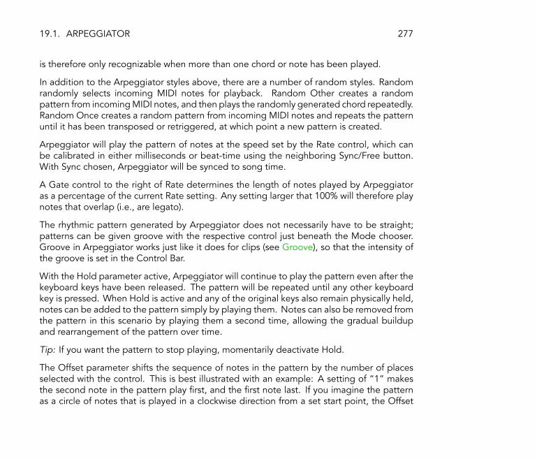
19.1. ARPEGGIATOR 277
is therefore only recognizable when more than one chord or note has been played.
In addition to the Arpeggiator styles above, there are a number of random styles. Randomrandomly selects incoming MIDI notes for playback. Random Other creates a randompattern from incoming MIDI notes, and then plays the randomly generated chord repeatedly.Random Once creates a random pattern from incoming MIDI notes and repeats the patternuntil it has been transposed or retriggered, at which point a new pattern is created.
Arpeggiator will play the pattern of notes at the speed set by the Rate control, which canbe calibrated in either milliseconds or beat-time using the neighboring Sync/Free button.With Sync chosen, Arpeggiator will be synced to song time.
A Gate control to the right of Rate determines the length of notes played by Arpeggiatoras a percentage of the current Rate setting. Any setting larger that 100% will therefore playnotes that overlap (i.e., are legato).
The rhythmic pattern generated by Arpeggiator does not necessarily have to be straight;patterns can be given groove with the respective control just beneath the Mode chooser.Groove in Arpeggiator works just like it does for clips (see Groove), so that the intensity ofthe groove is set in the Control Bar.
With the Hold parameter active, Arpeggiator will continue to play the pattern even after thekeyboard keys have been released. The pattern will be repeated until any other keyboardkey is pressed. When Hold is active and any of the original keys also remain physically held,notes can be added to the pattern simply by playing them. Notes can also be removed fromthe pattern in this scenario by playing them a second time, allowing the gradual buildupand rearrangement of the pattern over time.
Tip: If you want the pattern to stop playing, momentarily deactivate Hold.
The Offset parameter shifts the sequence of notes in the pattern by the number of placesselected with the control. This is best illustrated with an example: A setting of �1� makesthe second note in the pattern play �rst, and the �rst note last. If you imagine the patternas a circle of notes that is played in a clockwise direction from a set start point, the Offset

19.1. ARPEGGIATOR 278
parameter effectively rotates this circle counter-clockwise one note at a time, changingwhere in the pattern play begins.
With the Repeats parameter, the pattern can be set to repeat a speci�ed number of timesuntil it is retriggered. A setting of �inf� will repeat the pattern inde�nitely. Hint: Thisfeature provides an excellent way of emulating the strum of a guitar or playing a chord asan arpeggio once or twice. Another interesting effect can be achieved by combining thisfeature with the Retrigger parameter, which we will explain in a moment. This can be usedto create rhythmically generated arpeggios separated by pauses.
The Retrigger parameter resets the pattern so that it starts again from the beginning.Retriggering can be deactivated (Off), set to occur when new notes are pressed (Note) orset to occur at a speci�ed song position or beat-time (Beat). Beat retriggering can bespeci�ed in terms of notes or bars and is aligned with song position. An LED in the upperright corner of the section indicates when the pattern has been retriggered.
19.1.2 Transposition and Velocity Sections
The pattern generated by Arpeggiator can be transposed; the device's transposition controlsallow forcing this transposition into a speci�c major or minor key or (using the Transposechooser's Shift option) doing it in semitones. The distance between transposition steps isset in scale intervals (for Major and Minor transposition) or semitones (for Shift transposition)with the Distance control. Using the Steps parameter, you can choose the number of timesthe sequence is transposed: A setting of 8 will transpose the sequence a total of eight times,playing it in higher notes each time.
The dynamics of Arpeggiator are controlled using the velocity section. With Velocity setto On and Target set to 0, for example, the sequence will gradually fade out, eventuallyreaching 0 velocity. The Decay control sets the amount of time Arpeggiator takes to reachthe Target velocity. With Retrigger activated, retriggering of the sequence will also retriggerthe velocity slope.

19.2. CHORD 279
Tip: The velocity section's Retrigger option can be used in conjunction with Beat retriggeringto add rhythm to the dynamic slope.
19.2 Chord
The Chord Effect.
This effect assembles a chord, as the name implies, from each incoming note and up to sixothers of user-de�ned pitch. The Shift 1-6 knobs allow selecting the pitch of the notes thatcontribute to the chord from a range of +/- 36 semitones relative to the original. SettingShift 1 to +4 semitones and Shift 2 to +7 semitones, for example, yields a major chord inwhich the incoming note is the root.
The Velocity control beneath each Shift knob makes further harmonic sculpting possible,given that the instrument allows for changes in volume or timbre as function of velocity. Itis a relative control, with a range of 1 to 200 percent (100 percent de�ned as playing at avelocity equal to that of the incoming MIDI note). Use the Velocity controls to do anythingfrom adding slight overtones to washing out most of the other chord elements.
The order in which pitches are added to the chord is inconsequential: The effect of a+12 semitone shift added with the Shift 1 control, for example, is equal in effect to a +12

19.3. PITCH 280
semitone shift added with the Shift 6 control.
Note that no two notes of the same pitch can contribute to the chord, and that selecting thesame shift value twice (e.g., +8 semitones on both Shift 2 and Shift 3) will result in the lattercontrol becoming gray, indicating that it is a duplicate and therefore not in use. Actually,there is no such thing as two notes with the same pitch playing at the same time within theentire Live universe.
19.3 Pitch
The Pitch Effect.
Pitch is a transposition tool that changes incoming note pitch by +/- 48 semitones.
The Range and Lower Limit controls act together to set a pitch range through which notesare allowed to pass. Notes outside of the de�ned pitch range will be blocked, and theeffect's LED light will �ash when this happens.
Notes outside of the pitch range are limited based on their untransposed pitch, prior to thetransposition stage of the effect.
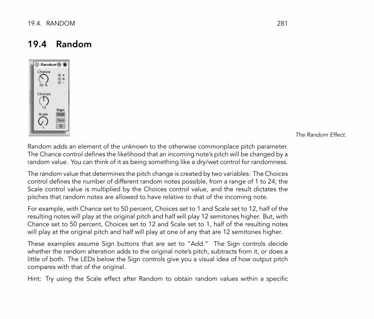
19.4. RANDOM 281
19.4 Random
The Random Effect.
Random adds an element of the unknown to the otherwise commonplace pitch parameter.The Chance control de�nes the likelihood that an incoming note's pitch will be changed by arandom value. You can think of it as being something like a dry/wet control for randomness.
The random value that determines the pitch change is created by two variables: The Choicescontrol de�nes the number of different random notes possible, from a range of 1 to 24; theScale control value is multiplied by the Choices control value, and the result dictates thepitches that random notes are allowed to have relative to that of the incoming note.
For example, with Chance set to 50 percent, Choices set to 1 and Scale set to 12, half of theresulting notes will play at the original pitch and half will play 12 semitones higher. But, withChance set to 50 percent, Choices set to 12 and Scale set to 1, half of the resulting noteswill play at the original pitch and half will play at one of any that are 12 semitones higher.
These examples assume Sign buttons that are set to �Add.� The Sign controls decidewhether the random alteration adds to the original note's pitch, subtracts from it, or does alittle of both. The LEDs below the Sign controls give you a visual idea of how output pitchcompares with that of the original.
Hint: Try using the Scale effect after Random to obtain random values within a speci�c

19.5. SCALE 282
harmonic range.
19.5 Scale
The Scale Effect.
Scale alters incoming note pitch based on a scale mapping. Each incoming note is givenan outgoing equivalent on the X-Y scale map of the effect: All incoming Cs, for example,might be converted to outgoing Ds.
The X-Y scale map is 12 squares in length and width, corresponding to the 12 notes in a fulloctave. Darker squares represent the black keys on a keyboard. The base of the diagonalscale (the lower left square) shown on the map can be changed using the Base control. TheX-axis of the map shows incoming note values, and the Y-axis their outgoing equivalents.Use mouse-clicks to move or delete the yellow squares, which de�ne where an incomingnote will be sent on the scale. (Deleting a note on the scale map means that it will no longerplay.)
The Range and Lower Limit controls de�ne the note range within which scale mappingwill take effect. Outside of the range de�ned by these controls, the Scale effect will beinapplicable, and the LED light will �ash to indicate that some notes are not being processed

19.6. VELOCITY 283
by the effect, but are playing at their unaltered pitch.
19.6 Velocity
The Velocity Effect.
Velocity re-maps the 127 MIDI note velocity values. The Out Low and Out Hi knobs controlthe outgoing velocity (from 1 to 127), which is represented by the Y-axis of the X-Y display.Incoming velocities that are shown in the display are within the range chosen by the InLow and In Hi choosers, and are represented on the X-axis. The resulting curve shows howvelocity is being altered by the effect.
If In Low and Out Low are both set to 1, and Out Hi and In Hi are set to 127, the display willshow a straight diagonal line that indicates the equivalent of an effect bypass: Softly playednotes are being output quietly and vice versa. If instead, Out Hi is set to 1 and out Low to127, the slope of the line will be reversed, and softly played notes will actually produce theloudest output.
What happens to incoming notes that are outside of the range set with the In Low and InHigh controls? This depends on which Mode is selected. Clip Mode does just what it says:It clips incoming note velocities so that they stay within the range. Gate Mode removes

19.6. VELOCITY 284
incoming notes altogether if their velocities are outside of the range. You will see the littleLED in the effect �ash when a note is blocked by gating. In Fixed Mode, the Out Hi velocityde�nes all outgoing note velocities, regardless of incoming note velocity.
The Random function adds or subtracts a random value to the all velocities, and is repre-sented by a gray area on the display curve.
The Drive and Compand controls can be combined to create more complex curves. Com-pand is a simultaneous expanding and compressing tool. When set to values greater than0, it forces incoming notes to the outer boundaries of the curve, making them play eitherloudly or softly. Compand values of less than 0, on the other hand, force outgoing velocitytoward the mid-range. Drive pushes all values in the curve to the outer extremes. Use thesetwo controls together to sculpt or even rede�ne the dynamic structure of a piece.
Chapter 20
Live Instrument Reference
Live comes with a selection of custom-designed, built-in instruments. The �Working withInstruments and Effects� chapter (see Working with Instruments and Effects) explains thebasics of using instruments in Live.
285

20.1. IMPULSE 286
20.1 Impulse
The Impulse Instrument.
Impulse is a drum sampler with complex modulative capabilities. The eight drum samplesloaded into Impulse's sample slots can be time-stretched, �ltered and processed by enve-lope, saturation, pan and volume components, nearly all of which are subject to randomand velocity-based modulation.
20.1.1 Sample Slots
Samples are dragged and dropped into Impulse's eight sample slots from the Browser or theSession and Arrangement Views. Samples can be deleted with your computer keyboard'sBackspace/Delete key.
Imported samples are automatically mapped onto your MIDI keyboard, providing that it isplugged in and acknowledged by Live. C3 on the keyboard will trigger the leftmost sample,and the other samples will follow suit in the octave from C3 to C4. Impulse's eight slots willappear labeled in the MIDI Editor's key tracks (see Editing MIDI Notes and Velocities) whenthe �Fold� button is active, even if the given key track is void of MIDI notes. Mapping can

20.1. IMPULSE 287
be transposed from the default by applying a Pitch device (see Pitch), or it can be rearrangedby applying a Scale device (see Scale).
Each of the eight samples has a proprietary set of parameters, located in the area below thesample slots and visible when the sample is clicked. Adjustments to sample settings are onlycaptured once you hit a new note � they do not affect currently playing notes. Note thatthis behavior also de�nes how Impulse reacts to parameter changes from clip envelopes orautomation, which are applied once a new note starts. If you want to achieve continuouschanges as a note plays, you may want to use the Simpler (see Simpler).
Slot 8's parameters also include a �Link� button, located in the lower left corner, which linksslot 8 with slot 7. Linking the two slots allows slot 7's activation to stop slot 8's playback, andvice versa. This was designed with a speci�c situation in mind (but can, of course, be usedfor other purposes): Naturalistic closed hi-hat cymbals will shut down open hi-hat cymbals.
Each slot can be played, soloed or muted using controls that appear when the mouse hoversover it.
20.1.2 Start, Tune and Stretch
The Start control de�nes where Impulse begins playing a sample, and can be set to upto 100 ms later than the actual sample beginning. The Transposition control adjusts thetransposition of the sample by +/- 48 semitones, and can be modulated by incoming notevelocity or a random value, as set in the appropriate �elds.
The Stretch control has values from -100 to 100 percent. Negative values will shorten thesample, and positive values will stretch it. Two different stretching algorithms are available:Mode A is ideal for low sounds, such as toms or bass, while Mode B is better for high sounds,such as cymbals. The Stretch value can also be modulated by MIDI note velocity.
20.1. IMPULSE 288
20.1.3 Filter
The Filter section offers a broad range of �lter types, each of which can impart differentsonic characteristics onto the sample by removing certain frequencies. The Frequencycontrol de�nes where in the harmonic spectrum the �lter is applied; the Resonance controlboosts frequencies near the points in the spectrum where frequencies are excluded by�ltering. Filter Frequency can be modulated by either a random value or by MIDI notevelocity.
20.1.4 Saturator and Envelope
The Saturator gives the sample a fatter, rounder, more analog sound, and can be switchedon and off using the appropriate switch. The Drive control boosts the signal and addsdistortion. Note: Turning Drive up makes almost every signal get much louder, and so willusually require that volume be lowered manually. Extreme Drive settings on low-pitchedsounds will produce the typical, overdriven analog synth drum sounds.
The envelope can be adjusted using the Decay control, which can be set to a maximum of60.0 seconds. Impulse has two decay modes: Trigger Mode allows the sample to decay withthe note; Gate Mode forces the envelope to wait for a note off message before beginningthe decay. This mode is useful in situations where you need variable decay lengths, as is thecase with hi-hat cymbal sounds.
20.1.5 Pan and Volume
Each sample has Volume and Pan controls that adjust amplitude and stereo positioning,respectively. Both controls can be modulated, Pan by velocity and a random value, andVolume by velocity only.
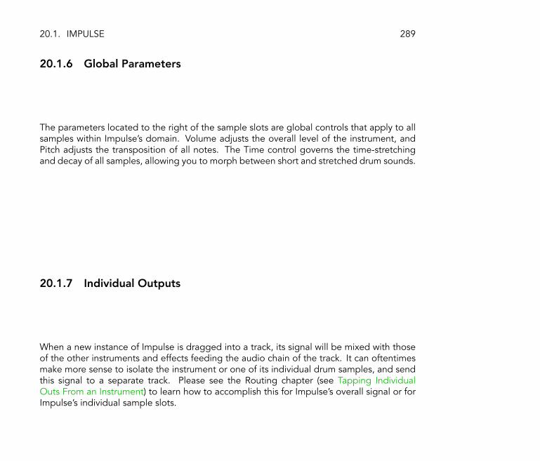
20.1. IMPULSE 289
20.1.6 Global Parameters
The parameters located to the right of the sample slots are global controls that apply to allsamples within Impulse's domain. Volume adjusts the overall level of the instrument, andPitch adjusts the transposition of all notes. The Time control governs the time-stretchingand decay of all samples, allowing you to morph between short and stretched drum sounds.
20.1.7 Individual Outputs
When a new instance of Impulse is dragged into a track, its signal will be mixed with thoseof the other instruments and effects feeding the audio chain of the track. It can oftentimesmake more sense to isolate the instrument or one of its individual drum samples, and sendthis signal to a separate track. Please see the Routing chapter (see Tapping IndividualOuts From an Instrument) to learn how to accomplish this for Impulse's overall signal or forImpulse's individual sample slots.

20.2. SIMPLER 290
20.2 Simpler
The Simpler Instrument.
Simpler is an instrument that integrates the basic elements of a sampler with a set of classicsynthesizer parameters. A Simpler voice plays a user-de�ned sample section, which is inturn processed by envelope, �lter, LFO, volume and pitch components.
20.2.1 Sample View
The Sample View displays the sample waveform. Samples can be dragged into Simplereither directly from the Browser, or from the Session or Arrangement View in the form ofclips. In the latter case, Simpler will utilize only the section of the sample demarcated bythe clip's start/end or loop markers. Samples can be replaced by dragging in a new sample.
20.2.2 Sample Controls
Simpler plays a speci�c region or loop of the sample, as determined by a group of samplecontrols.

20.2. SIMPLER 291
The Start and Length controls work together to specify where Simpler begins and ends itssweep of the sample. As the name implies, Start de�nes where sample playback starts.The sample will play for the length de�ned by the Length parameter. Both parameters arede�ned as a percentage of the whole region, so setting start to 25 percent and length to50 percent, for example, will start playback 1/4 of the way through the sample and stopplayback at the 3/4 mark (using 50 percent of the sample).
Samples are played by Simpler as one-shots or as loops, depending on whether or not theLoop switch is active. When looping is active, the Loop control dictates the length of theloop, starting from the end of the playing sample. Simpler will play the �rst instance of alooped sample beginning with the Start point, then continue playing only the length of theloop.
It is possible for glitches or pops to occur between a looped sample's start and end pointsdue to the discontinuity in waveform amplitude (i.e., the sample's loudness). The Snapswitch will help mitigate these by forcing Simpler's loop markers to snap to zero-crossingpoints in the sample (points where the amplitude is zero). Note: Snapping is based on theleft channel of stereo samples. It is therefore still possible, even with Snap activated, toencounter glitches in the right channel of a stereo sample.
You can also smooth the transition from loop end to loop start by using the Fade control,which crossfades the two points. This method is especially useful when working with long,textural samples.
20.2.3 Zoom
Quite often, one starts with a longer region of a sample and ends up using only a small partof it. Simpler's two Zoom buttons (�+� and �-�) allow you to zoom in around the selectedlength, or zoom out to access a larger area. When zooming in on small portions of longsamples, it will probably be necessary to repeatedly shrink the highlighted sample region,as Simpler will zoom no further than the length of this region. Note: After zooming in, the

20.2. SIMPLER 292
Start, Loop and Length parameters will be resized so that there is no audible difference.This means that the Start and Length values are altered by zooming, and automation or clipenvelopes utilizing these parameters will behave differently after the operation.
20.2.4 Envelope
Simpler contains the classic ADSR Envelope section, as seen in most synthesizers, for shapingthe dynamic structure of the sample. It also has two additional envelopes, one for the �lterand one for pitch, which are available by toggling the respective buttons in the envelopesection. Attack controls the time in milliseconds that it takes for the envelope to reachits peak value after a note is played. Decay controls the amount of time it takes for theenvelope to drop down to the Sustain level, which is held until the note is released. Releasetime is the amount of time after the end of the note that it takes for the envelope to dropfrom the Sustain level back down to zero.
The in�uence of envelopes on pitch and �lter cutoff can be decided using the envelopeamount controls in each of these sections.
20.2.5 Filter
The Filter section offers classic 12 dB or 24 dB low-pass, band-pass and high-pass �lters, aswell as a notch �lter, each of which can impart different sonic characteristics onto the sampleby removing certain frequencies from the waveform. The most important parameters arethe typical synth controls Frequency and Resonance. Frequency determines where in theharmonic spectrum the �lter is applied; Resonance boosts frequencies near the points inthe spectrum where frequencies are excluded by �ltering.
The best way to understand the effects of these controls is to play with them...
The Frequency parameter can be modulated by an LFO, note velocity and an envelope �

20.2. SIMPLER 293
each of which have an amount control in the Filter section. The Key (tracking) control allowsfor shifting the �lter's frequency according to note pitch.
20.2.6 LFO
The LFO (low-frequency oscillator) section offers square, sine, triangle, sawtooth up, saw-tooth down and random waveforms. The main control in this section is the Rate control,which changes the LFO frequency within a range of 0.05 to 30 Hz. LFOs are applied individ-ually to each voice, or played note, in Simpler. Square, triangle and sawtooth LFOs restarteach time a new voice is played, while sine and random do not. The Key parameter changesthe de�nition of each LFO's Rate as a function of the pitch of incoming notes. A high Keysetting assigns higher notes a higher LFO rate. If Key is set to zero, all voices' LFOs havethe same rate and may just differ in their phase.
The LFO will modulate the �lter, pitch, panorama and volume according to the setting ofthe LFO amount controls in each of these sections.
The time taken for the LFO to reach normal level can be set with the Attack control.
20.2.7 Pitch, Pan, Volume and Voices
Simpler plays back a sample at its original pitch if the incoming MIDI note is C3, however theTranspose control allows transposing this by +/- 48 semitones. Pitch can also be modulatedby an LFO or pitch envelope using the amount controls in this section. The pitch envelope isespecially helpful in creating percussive sounds. Simpler reacts to pitch bend MIDI messageswith a sensitivity of +/- 5 semitones. You can also modulate the Transpose parameter withclip envelopes and external controllers.
The Voices parameter sets the maximum number of voices that Simpler can play simultane-ously. If more voices are trying to play than what you have allocated with the Voice control,
20.2. SIMPLER 294
�voice stealing� will take place, in which the oldest voice(s) will be dropped in favor of thosethat are new. For example, if your Voices parameter is set to 8, and ten voices are all vying tobe played, the two oldest voices will be dropped. (Simpler does try to make voice stealingas subtle as possible.) A small LED near the Voices control �ashes when a voice has beenstolen.
Panorama can be set with the Pan control, and this control can be further affected by arandom factor or modulated by the LFO.
Finally, the output volume of Simpler is controlled by the Volume control, and can also bedependent upon note velocity, as adjusted by the Velocity control. Tremolo effects can beachieved by increasing the in�uence of the LFO over volume with the respective control.
20.2.8 Glide and Spread
Simpler includes a polyphonic glide function. When this function is activated, new noteswill start with the pitch of the last note played and then slide gradually to their own playedpitch. Glide can be turned on or off and adjusted with the Glide Time control.
Simpler also offers a special Spread parameter that creates a rich stereo chorus by usingtwo voices per note and panning one to the left and one to the right. The two voices aredetuned, and the amount of detuning can be adjusted with the Spread control.
Tip: Whether or not spread is applied to a particular note depends upon the setting ofthe Spread parameter during the note-on event. To achieve special effects, you could, forinstance, create a sequence where Spread is 0 most of the time and turned on only for somenotes. These notes will then play in stereo, while the others will play mono.

20.3. OPERATOR 295
20.2.9 Strategies for Saving CPU Power
Real-time synthesis needs lots of computing power. However, there are strategies forreducing CPU load. Save the CPU spent on Simpler by doing some of the following:
� Turn off the Filter if it is not needed.
� Use �lter types that are less expensive when possible. A �lter's cost correlates with thesteepness of its slope � a �LP 24� is more expensive than a �LP 12.�
� Turn off the LFO for a slightly positive in�uence on CPU.
� Stereo samples need signi�cantly more CPU than mono samples, as they require twicethe processing.
� Decrease the number of simultaneously allowed voices with the Voice control.
20.3 Operator
The OperatorInstrument.
20.3. OPERATOR 296
Operator is an advanced and �exible synthesizer that combines the concept of �frequencymodulation� (FM) with classic subtractive synthesis. It utilizes four multi-waveform oscillatorsthat can modulate each other's frequencies, creating very complex timbres from a limitednumber of objects. Operator includes a �lter section, an LFO and global controls, as wellas individual envelopes for the oscillators, �lter, LFO and pitch.
The full version of Operator is not included with the standard version of Live, but is a specialfeature available for purchase separately. For details, please visit the Ableton webshop1,where you will be offered the opportunity to buy Operator online. Once you have purchasedOperator, you will need to unlock it before using it, as described in the chapter on unlocking(see Unlocking Live).
20.3.1 General Overview
The interface of Operator consists of two parts: the display surrounded on either side bythe shell. The shell offers the most important parameters in a single view and is divided intoeight sections. On the left side, you will �nd four oscillator sections, and on the right sidefrom top to bottom, the LFO, the �lter section, the pitch section and the global parameters.If you change one of the shell parameters, the display in the center will automatically showthe details of the relevant section. When creating your own sounds, for example, you canconveniently access the level and frequency of all oscillators at once via the shell, and thenadjust each individual oscillator's envelope, waveform and other parameters in its display.
Operator can be folded with the triangular button at its upper left. This is convenient if youdo not need to access the display details.
1http://www.ableton.com/shop

20.3. OPERATOR 297
Operator Folded.
Each of Operator's oscillators can either output its signal directly or use its signal to modulateanother oscillator. Operator offers nine prede�ned algorithms that determine how theoscillators are connected. An algorithm is chosen by clicking on one of the structure iconsin the global display, which will appear if the bottom right (global) section of the shell isselected. Signals will �ow from top to bottom between the oscillators shown in an algorithmicon.
Operator's GlobalDisplay.
Typically, FM synthesis makes use of pure sine waves, creating more complex waveformsvia modulation. However, in order to simplify sound design and to create a wider range of

20.3. OPERATOR 298
possible sounds, we designed Operator to produce a variety of other waveforms, includingnoise. The instrument is made complete with an LFO, a pitch envelope and a �lter section.Note that lots of �classic� FM synthesizers create fantastic sounds without using �lters atall, so we suggest exploring the possibilities of FM without the �lter at �rst, adding it laterif necessary.
Operator will keep you busy if you want to dive deep into sound design! If you want to breakthe universe apart completely and reassemble it, you should also try modulating Operator'scontrols with clip envelopes (see Clip Envelopes) or track automation (see Automation andEditing Envelopes).
20.3.2 Oscillator Section and Aliasing
Oscillator D's Displayand Shell Parameters.
The oscillators can basically play back �ve waveform types � sine, square, sawtooth, triangleand noise � as chosen from the Wave chooser in the individual oscillator displays. The �rst ofthese waveforms is a pure, mathematical sine wave, which is usually the �rst choice for manyFM timbres. Since FM synthesis has a long tradition in hardware synthesizers, we addedsome variations of the pure sine wave that allow for more realistic modeling of vintage digitalsynthesizers. The differences between these sine waves are very subtle, and whether or not
20.3. OPERATOR 299
they are audible is highly dependant upon the individual sound. We also added �Sine 4 Bit�and �Sine 8 Bit� to provide the retro sound adored by C64 fans, and �Saw D� and �SquareD� digital waveforms, which are especially good for digital bass sounds. Another specialcase is the noise waveform. This is not real noise, generated by a random generator, but alooping noise sample. For more �statistical� noise, one could modulate the noise oscillatorwith another oscillator, or with real noise from the LFO. The square, triangle and sawtoothwaveforms are resynthesized approximations of the ideal shape. The numbers included inthe displayed name (e.g., �Sq6�) de�ne how many harmonics are used for the resynthesis.Lower numbers sound mellower and are less likely to create aliasing when used on highpitches.
Hint: Oscillator waveforms can be copied and pasted from one oscillator to another usingthe (PC) / Ctrl (Mac) context menu.
Aliasing distortion is a common side effect of all digital synthesis and is the result of the�nite sample rate and precision of digital systems. It mostly occurs at high frequencies. FMsynthesis is especially likely to produce this kind of effect, since one can easily create soundswith lots of high harmonics. This also means that more complex oscillator waveforms, suchas �Saw32,� tend to be more sensitive to aliasing than pure sine waves. Aliasing is a two-fold beast: A bit of it can be exactly what is needed to create a cool sound, and a bit toomuch can make the timbre unplayable, as the perception of pitch is lost when high notessuddenly fold back into arbitrary pitches. The Tone parameter in the global section allowsfor controlling aliasing. Its effect is sometimes similar to a low-pass �lter, but this dependson the nature of the sound itself and cannot generally be predicted. If you want to familiarizeyourself with the sound of aliasing, turn Tone up fully and play a few very high notes. Youwill most likely notice that some notes sound completely different from other notes. Now,turn Tone down and the effect will be reduced, but the sound will be less bright.
The frequency of an oscillator can be adjusted in the shell with its Coarse and Fine controls.An oscillator's frequency usually follows that of played notes, but for some sounds it mightbe useful to set one or more oscillators to �xed frequencies. This can be done for eachindividual oscillator by activating the Fixed option. This allows the creation of sounds in

20.3. OPERATOR 300
which only the timbre will vary when different notes are played, but the tuning will stay thesame. Fixed Mode would be useful, for example, in creating live drum sounds. Fixed Modealso allows producing very low frequencies down to 0.1 Hz. Note that when Fixed Mode isactive, the frequency of the oscillator is controlled in the shell with the Frequency (Freq) andMultiplier (Multi) controls.
Operator includes a special Osc<Vel control for each oscillator that allows altering frequencyas a function of velocity. This feature can be very useful when working with sequencedsounds in which the velocity of each note can be adjusted carefully. Part of this functionalityis the adjacent quantize control. If this control is activated, the frequency will only move inwhole numbers, just as if the Coarse control were being manually adjusted. If quantize isnot activated, the frequency will be shifted in an unquantized manner, leading to detunedor inharmonic sounds (which very well could be exactly what you want...).
The amplitude of an oscillator depends on the Level setting of the oscillator in the shelland on its envelope (see Envelopes), which is shown in its display and can be adjustedfrom there. It can also be modi�ed by note velocity and note pitch with the Level<Vel andLevel<Key parameters available in the lower portion of each oscillator's display.
The phase of each oscillator can be adjusted using the Phase control in its display.
As explained earlier (see General Overview) oscillators can modulate each other when setup to do so with the global display's algorithms. When an oscillator is modulating anotheroscillator, two main properties de�ne the result: the amplitude of the modulating oscillatorand the frequency ratio between both oscillators. Note that Oscillator D can modulate itselfvia the Feedback parameter available in its display.

20.3. OPERATOR 301
20.3.3 LFO Section
Operator's LFOParameters.
The LFO in Operator can practically be thought of as a �fth oscillator. It runs at an audio rate,and it modulates the frequency of the other oscillators. It is possible to switch modulation bythe LFO on or off for each individual oscillator (and the �lter) using the Destination buttonsin the LFO's display. The LFO can also be turned off if it is unused.
The LFO offers a choice of classic LFO waveforms, sample and hold (S&H), and noise.Sample and hold uses random numbers chosen at the rate of the LFO, creating the randomsteps useful for typical retro-futuristic sci-� sounds. The noise waveform is simply band-pass-�ltered noise.
Tip: FM synthesis can be used to create fantastic percussion sounds, and using the LFOwith the noise waveform is the key to great hi-hats and snares.
The frequency of the LFO is determined by the LFO Rate control in the shell, as well as thelow/high setting of the adjacent LFO Range switch. The frequency of the LFO can follownote pitch, be �xed or be set to something in between. This is de�ned by the Rate<Keyparameter in the LFO's display.
The intensity of the LFO is set by the LFO Mod control in the shell. This parameter can bemodulated by note velocity via the display's Amt<Vel control. The LFO's intensity is also

20.3. OPERATOR 302
affected by its envelope (see Envelopes).
20.3.4 Envelopes
Operator has seven envelopes: one for each oscillator, a �lter envelope, a pitch envelopeand an envelope for the LFO. All envelopes are constructed similarly and feature somespecial looping modes.
An envelope's shape is de�ned by six parameters: three rates and three levels. A rate is thetime it takes to go from one level to the next. For instance, a typical pad sound starts withthe initial level �-inf dB� (which is silence), moves with an attack rate to its peak level, movesfrom there to the sustain level with a decay rate, and then �nally, after note-off occurs,back to �-inf dB� at the release rate. Operator's display provides a good overview of theactual shape of any particular envelope and lets you directly adjust the curve by clicking anddragging.
Hint: Envelope shapes can be copied and pasted from one place to another in Operatorusing the (PC) / Ctrl (Mac) context menu.
With FM synthesis, it is possible to create spectacular, endless, permuting sounds; the keyto doing this is looping envelopes. Loop Mode can be activated in the lower left corner ofthe display. If an envelope in Operator is in Loop Mode and reaches sustain level while thenote is still being held, it will be retriggered. The rate for this movement is de�ned by theLoop Time parameter. (Note that envelopes in Loop Mode can loop very quickly and cantherefore be used to achieve effects that one would not normally expect from an envelopegenerator.)
While Loop Mode is good for textures and experimental sounds, Operator also includes Beatand Sync Modes, which provide a simple way of creating rhythmical sounds. If set to BeatMode, an envelope will restart after the beat time selected from the Repeat chooser. In BeatMode, the repeat time is de�ned in fractions of song time, but notes are not quantized.If you play a note a bit out of sync, it will repeat perfectly but stay out of sync. In Sync
20.3. OPERATOR 303
Mode however, the �rst repetition is quantized to the nearest 16th note and, as a result, allfollowing repetitions are synced to the song tempo. Note that Sync Mode only works if thesong is playing, and otherwise it will behave like Beat Mode.
Note: To avoid the audible clicks caused by restarting from its initial level, a looped envelopewill restart from its actual level and move with the set attack rate to peak level.
The rates of all the envelopes in Operator can be scaled in unison by the Time control inthe global section of the shell. Note that beat-time values in Beat and Sync Modes are notin�uenced by the global Time parameter. Envelope rates can be further modi�ed by notepitch, as dictated by the Time<Key parameter in the global section's display. The rate of anindividual envelope can also be modi�ed by velocity using the Time<Vel parameter. Thesemodulations in conjunction with the loop feature can be used to create very, very complexthings...
The pitch envelope can be turned on or off for each individual oscillator and for the LFOusing the Destination A-D and LFO buttons in its display. It can also be turned off altogethervia the pitch section of the shell. The pitch envelope amount is adjusted with the adjacentPitch Env control.
Tip: If the pitch envelope is only applied to the LFO and is looping, it can serve as anotherLFO, modulating the rate of the �rst. And, since the envelope of the LFO itself can loop, itcan serve as a third LFO modulating the intensity of the �rst!

20.3. OPERATOR 304
20.3.5 Filter Section
Operator's Filter Section.
As mentioned earlier, the �lters are not the main focus of this instrument. However, theycan be very useful for modifying the sonically rich timbres created by the oscillators. And,since the oscillators also provide you with the classic waveforms of analog synthesizers, youcan very easily build a subtractive synthesizer with them.
The �lter section offers 12 dB low-pass, band-pass, high-pass and notch �lters. Note thatthe notch �lter is not of true notch �lter design but a bell-shaped curve with very low gain,which removes more of the frequencies around the center.
Filter cutoff frequency and resonance can be adjusted in the shell. Filter frequency can alsobe modulated by note velocity, note pitch, the LFO and the �lter envelope (see Envelopes).The Freq<Vel, Freq<Key and Envelope controls in the �lter's display set these three func-tions, respectively.
20.3.6 Global Controls
The maximum number of Operator voices (notes) playing simultaneously can be adjustedwith the Voices parameter in the global display. Ideally, one would want to leave this setting

20.3. OPERATOR 305
high enough so that no voices would be turned off while playing, however a setting between6 and 12 is usually more realistic when considering CPU power (see Strategies for SavingCPU Power).
Tip: Some sounds should play monophonically by nature, which means that they shouldonly use a single voice. (A �ute is a good example.) In these cases, you can set Voices to 1.If Voices is set to 1, another effect occurs: Overlapping voices will be played legato, whichmeans that the envelopes will not be retriggered from voice to voice, and only pitch willchange.
A high quality setting (HiQ) can be switched on and off in the global display, controlling theinterpolation algorithm of the oscillators and LFO. This setting will affect the sound of somewaveforms more than others (especially the noise waveform) and also affects CPU resources(see Strategies for Saving CPU Power).
Global Volume and Transpose controls for the instrument can be found in the global sectionof the shell, and a Pan control is located in the global section's display. Pan can be modulatedby a random factor or by note pitch, using the adjacent Rnd and Key controls, respectively.
MIDI pitch bend messages will affect Operator as de�ned by the PB Range control in thepitch section of the display.
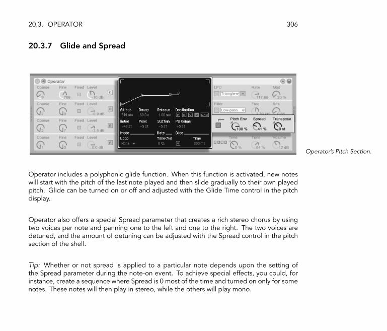
20.3. OPERATOR 306
20.3.7 Glide and Spread
Operator's Pitch Section.
Operator includes a polyphonic glide function. When this function is activated, new noteswill start with the pitch of the last note played and then slide gradually to their own playedpitch. Glide can be turned on or off and adjusted with the Glide Time control in the pitchdisplay.
Operator also offers a special Spread parameter that creates a rich stereo chorus by usingtwo voices per note and panning one to the left and one to the right. The two voices aredetuned, and the amount of detuning can be adjusted with the Spread control in the pitchsection of the shell.
Tip: Whether or not spread is applied to a particular note depends upon the setting ofthe Spread parameter during the note-on event. To achieve special effects, you could, forinstance, create a sequence where Spread is 0 most of the time and turned on only for somenotes. These notes will then play in stereo, while the others will play mono.

20.3. OPERATOR 307
20.3.8 Strategies for Saving CPU Power
If you want to save CPU power, turn off features that you do not need or reduce the numberof voices. Speci�cally, turning off the �lter or the LFO if they do not contribute to the soundwill save CPU power.
For the sake of saving CPU resources, you will also usually want to reduce the number ofvoices to something between 6 and 12, and carefully use the Spread feature. The highquality setting can also be turned off to conserve CPU resources.
Note that turning off the oscillators will not save CPU power.
20.3.9 Finally...
Operator is the result of an intense preoccupation with FM synthesis and a love and dedi-cation to the old hardware FM synthesizers, such as the Yamaha SY77, the Yamaha TX81Zand the NED Synclavier II. FM synthesis was �rst explored musically by the composer andcomputer music pioneer John Chowning in the mid-1960s. In 1973, he and Stanford Uni-versity began a relationship with Yamaha that lead to one of the most successful commercialmusical instruments ever, the DX7.
John Chowning realized some very amazing and beautiful musical pieces based on a syn-thesis concept that you can now explore yourself simply by playing with Operator in Live.
We wish you loads of fun with it!
20.3.10 The Complete Parameter List
The function of each Operator parameter is explained in the forthcoming sections. Remem-ber that you can also access explanations of controls in Live (including those belonging toOperator) directly from the software by placing the mouse over the control and reading the

20.3. OPERATOR 308
text that appears in the Info View (see Using the Info View and Index). Parameters in this listare grouped into sections based on where they appear in Operator.
Global Shell and Display
Time- This is a global control for all envelope rates.
Tone- Operator is capable of producing timbres with very high frequencies, which cansometimes lead to aliasing artifacts. The Tone setting controls the high frequency contentof sounds. Higher settings are typically brighter but also more likely to produce aliasing.
Volume- This sets the overall volume of the instrument.
Algorithm- An oscillator can modulate other oscillators, be modulated by other oscillators,or both. The algorithm de�nes the connections between the oscillators and therefore has asigni�cant impact on the sound that is created.
Voices- This sets the maximum number of notes that can sound simultaneously. If morenotes than available voices are requested, the oldest notes will be cut off.
High Quality (HiQ)- This changes the interpolation algorithm of the oscillators and the LFO.If turned off, some timbres will sound more rough, especially the noise waveform. Turningthis off will also save some CPU power.
Time<Key- The rates of all envelopes can be controlled by note pitch. If the global Time<Keyparameter is set to higher values, the envelopes run faster when higher notes are played.
Pan- Use this to adjust the panorama of each note. This is especially useful when modulatedwith clip envelopes.
Pan<Key (Key)- If Pan<Key is set to higher values, low notes will pan relatively more to theleft channel, and higher notes to the right. Typically this is used for piano-like sounds.
Pan<Random (Rnd)- This de�nes the extent to which notes are randomly distributed betweenthe left and right channels.

20.3. OPERATOR 309
Pitch Shell and Display
Pitch Envelope On- This turns the pitch envelope on and off. Turning it off if it is unusedsaves some CPU power.
Pitch Envelope Amount (Pitch Env)- This sets the intensity of the pitch envelope. A value of100% means that the pitch change is exactly de�ned by the pitch envelope's levels. A valueof -100% inverts the sign of the pitch envelope levels.
Spread- If Spread is turned up, the synthesizer uses two detuned voices per note, oneeach on the left and right stereo channels, to create chorusing sounds. Spread is a veryCPU-intensive effect.
Transpose- This is the global transposition setting for the instrument. Changing this param-eter will affect notes that are already playing.
Pitch Bend Range (PB Range)- This de�nes the effect of MIDI pitch bend messages.
Pitch Envelope Rates<Velocity (Time<Vel)- This parameter exists for �lter, pitch, LFO andvolume envelopes. It is therefore listed in the section on envelopes (see Envelope Display).
Glide (G)- With Glide on, notes will slide from the pitch of the last played note to theirplayed pitch. Note that all envelopes are not retriggered in this case if notes are beingplayed legato.
Glide Time (Time)- This is the time it takes for a note to slide from the pitch of the lastplayed note to its �nal pitch when Glide is activated. This setting has no effect if Glide isnot activated.
Pitch Envelope to Osc (Destination A-D)- The pitch envelope affects the frequency of therespective oscillator if this is turned on.
Pitch Envelope to LFO (Destination LFO)- The pitch envelope affects the frequency of theLFO if this is turned on.
20.3. OPERATOR 310
Filter Shell and Display
Filter On- This turns the �lter on and off. Turning it off when it is unused saves CPU power.
Filter Type- Low-pass, band-pass and high-pass are second order �lters with resonance.Their names imply the part of the spectrum they affect. The notch �lter passes everythingapart from its center frequency and is more audible with low resonance settings.
Filter Frequency (Freq)- This de�nes the center or cutoff frequency of the �lter. Note thatthe resulting frequency may also be modulated by note velocity and by the �lter envelope.
Filter Resonance (Res)- This de�nes the resonance around the �lter frequency of the low-passand high-pass �lters, and the width of the band-pass and notch �lters.
Filter Frequency<Velocity (Freq<Vel)- Filter frequency is modulated by note velocity accord-ing to this setting.
Filter Frequency<Key (Freq<Key)- Filter frequency is modulated by note pitch according tothis setting. A value of 100% means that the frequency doubles per octave. The centerpoint for this function is C3.
Filter Envelope Rates<Velocity (Time<Vel)- This parameter exists for �lter, pitch, LFO andvolume envelopes. It is therefore listed in the section on envelopes (see Envelope Display).
Filter Frequency<Envelope (Envelope)- Filter frequency is modulated by the �lter envelopeaccording to this setting. A value of 100% means that the envelope can create a maximumfrequency shift of approximately 9 octaves.
LFO Shell and Display
LFO On- This turns the LFO (low-frequency oscillator) on and off. Turning it off when it isunused saves some CPU power.

20.3. OPERATOR 311
LFO Waveform- Select from among several typical LFO waveforms. Sample and Hold createsrandom steps, and Noise supplies band-pass-�ltered noise. All waveforms are band-limitedto avoid unwanted clicks. Cyclic waveforms restart with each note-on message.
LFO Range- The LFO covers an extreme frequency range. Choose Low for a range from 50seconds to 30 Hz, or Hi for 8 Hz to 12 kHz. Due to the possible high frequencies, the LFOcan also function as a �fth oscillator.
LFO Rate (Rate)- This sets the rate of the LFO. The actual frequency also depends on thesetting of the LFO Range and the LFO Rate<Key controls.
LFO Amount (Mod)- This sets the intensity of the LFO. Note that the actual effect alsodepends on the LFO envelope.
LFO to Osc (Destination A-D)- The LFO modulates the frequency of the respective oscillatorif this is turned on.
LFO Envelope Rates<Velocity (Time<Vel)- This parameter exists for �lter, pitch, LFO andvolume envelopes. It is therefore listed in the section on envelopes (see Envelope Display).
LFO Rate<Key (Rate<Key)- The LFO's frequency can be a function of note pitch. If this is setto 100%, the LFO will double its frequency per octave, functioning like a normal oscillator.
LFO Amount<Velocity (Amt<Vel)- This setting adjusts modulation of the LFO intensity bynote velocity.
Oscillators A-D Shell and Display
Osc On- This turns the oscillator on and off.
Osc Coarse Frequency (Coarse)- The relationship between oscillator frequency and notepitch is de�ned by the Coarse and Fine parameters. Coarse sets the ratio in whole numbers,creating a harmonic relationship.

20.3. OPERATOR 312
Osc Fine Frequency (Fine)- The relationship between oscillator frequency and note pitchis de�ned by the Coarse and Fine parameters. Fine sets the ratio in fractions of wholenumbers, creating an inharmonic relationship.
Osc Fixed Frequency On (Fixed)- In Fixed Mode, oscillators do not respond to note pitchbut instead play a �xed frequency.
Osc Fixed Frequency (Freq)- This is the frequency of the oscillator in Hertz. This frequencyis constant, regardless of note pitch.
Osc Fixed Multiplier (Multi)- This is used to adjust the range of the �xed frequency. Multiplythis value with the value of the oscillator's Freq knob to get actual frequency in Hz.
Osc Output Level (Level)- This sets the output level of the oscillator. If this oscillator ismodulating another, its level has signi�cant in�uence on the resulting timbre. Higher levelsusually create bright and/or noisy sounds.
Osc Waveform (Wave)- Choose from a collection of carefully selected waveforms, includingslight derivations of sine waves that are especially useful for creating emulations of vintagedigital hardware synthesizers.
Osc Phase (Phase)- This sets the initial phase of the oscillator. The range represents onewhole cycle.
Osc Frequency<Velocity (Osc<Vel)- The frequency of an oscillator can be modulated bynote velocity. Positive values raise the oscillator's pitch with greater velocities, and negativevalues lower it.
Osc Freq<Vel Quantized (Q)- This allows quantizing the effect of the Frequency<Velocityparameter. If activated, the sonic result is the same as manually changing the Coarseparameter for each note.
Volume Envelope Rates<Velocity (Time<Vel)- This parameter exists for �lter, pitch, LFO andvolume envelopes. It is therefore listed in the section on envelopes (see Envelope Display).

20.3. OPERATOR 313
Osc Output Level<Velocity (Vel)- This de�nes how much the oscillator's level depends uponnote velocity. Applying this to modulating oscillators creates velocity-dependent timbres.
Osc Output Level<Key (Key)- This de�nes how much the oscillator's level depends uponnote pitch. The center point for this function is C3.
Osc D Feedback (Feedback)- Osc D can modulate itself. The modulation is dependent notonly on the setting of the feedback control but also on the oscillator level and the envelope.Higher feedback creates a more complex resulting waveform.
Envelope Display
Envelope Attack Time (Attack)- This sets the time it takes for a note to reach the peak level,starting from the initial level. The shape of this segment of the envelope is linear.
Envelope Decay Time (Decay)- This sets the time it takes for a note to reach the sustain levelfrom the peak level. The shape of this segment of the envelope is exponential.
Envelope Release Time (Release)- This is the time it takes for a complete fade-out of a noteafter a note-off message is received. The shape of this segment is exponential. The notewill fade out from the value of the envelope at the moment the note-off message occurs,regardless of which segment is currently active.
Envelope Initial Level (Initial)- This sets the initial value of the envelope.
Envelope Peak Level (Peak)- This is the peak level at the end of the note attack.
Envelope Sustain Level (Sustain)- This is the sustain level at the end of the note decay. Theenvelope will stay at this level until note release unless it is in Loop, Sync or Beat Mode.
Envelope Mode (Mode)- If this is set to Loop, the envelope will start again after the end ofthe decay segment. If set to Beat or Sync, it will start again after a given beat-time. In SyncMode, this behavior will be quantized to song time.

20.3. OPERATOR 314
Envelope Beat/Sync Rate (Repeat)- The envelope will be retriggered after this amount ofbeat-time, as long as it is still on. When retriggered, the envelope will move at the givenattack rate from the current level to the peak level.
Envelope Loop Time (Time)- If a note is still on after the end of the decay/sustain segment,the envelope will start again from its initial value. The time it takes to move from the sustainlevel to the initial value is de�ned by this parameter.
Envelope Rates<Velocity (Time<Vel)- Envelope segments will be modulated by note velocityas de�ned by this setting. This is especially interesting if the envelopes are looping. Notethat this modulation does not in�uence the beat-time in Beat or Sync Modes, but theenvelope segments themselves.

Chapter 21
MIDI and Key Remote Control
To liberate the musician from the mouse, most of Live's controls can be remote-controlledwith an external MIDI controller and the computer keyboard. This chapter describes thedetails of mapping to the following speci�c types of controls in Live's user interface:
1. Session View slots. Note that MIDI and computer key assignments are bound tothe slots, not to the clips they contain.
2. Switches and buttons, among them the Track and Device Activator switches, theControl Bar's tap tempo, metronome and transport controls.
3. Radio buttons. A radio button selects from among a number of options. Oneinstance of a radio button is the crossfader assignment section (see Using Live'sCrossfader) in each track, which offers three options: The track is assigned to thecrossfader's A position, the track is unaffected by the crossfader, or the track isaffected by the crossfader's B position.
315
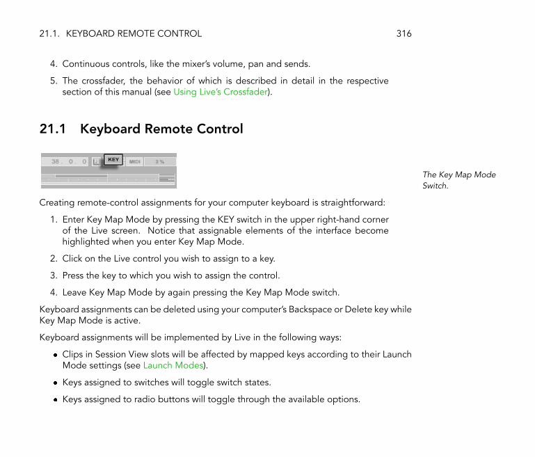
21.1. KEYBOARD REMOTE CONTROL 316
4. Continuous controls, like the mixer's volume, pan and sends.
5. The crossfader, the behavior of which is described in detail in the respectivesection of this manual (see Using Live's Crossfader).
21.1 Keyboard Remote Control
The Key Map ModeSwitch.
Creating remote-control assignments for your computer keyboard is straightforward:
1. Enter Key Map Mode by pressing the KEY switch in the upper right-hand cornerof the Live screen. Notice that assignable elements of the interface becomehighlighted when you enter Key Map Mode.
2. Click on the Live control you wish to assign to a key.
3. Press the key to which you wish to assign the control.
4. Leave Key Map Mode by again pressing the Key Map Mode switch.
Keyboard assignments can be deleted using your computer's Backspace or Delete key whileKey Map Mode is active.
Keyboard assignments will be implemented by Live in the following ways:
� Clips in Session View slots will be affected by mapped keys according to their LaunchMode settings (see Launch Modes).
� Keys assigned to switches will toggle switch states.
� Keys assigned to radio buttons will toggle through the available options.
21.2. MIDI REMOTE CONTROL 317
Please be sure not to confuse keyboard remote-control functionality with Live's ability to usethe keyboard as a pseudo-MIDI device (see Playing MIDI With the Computer Keyboard) thatcan generate MIDI notes from computer keystrokes for use with instruments.
21.2 MIDI Remote Control
Live can be controlled remotely with an external MIDI device such as a keyboard or controllerbox. Live also supports Mackie Control, a topic that is covered in a separate chapter (seeMackie Control) in this manual, for completely mouse-free program operation.
Before we explain how remote-control assignments are made and implemented, let us �rstmake the distinction between MIDI remote control and a separate use of MIDI in Live:input for MIDI tracks. Let's say that you are, for instance, using a MIDI keyboard to playan instrument in one of Live's MIDI tracks (see Working with Instruments and Effects). Ifyou assign F2 on your MIDI keyboard to a Session View Clip Launch button, that key willcease play F2 on your MIDI track's instrument, as it now �belongs� solely to the Clip Launchbutton.
MIDI keys that become part of remote-control assignments can no longer be used as inputfor MIDI tracks.
This is a common cause of confusion that can be easily resolved by looking at the ControlBar's MIDI indicators (see MIDI In/Out Indicators).
21.2.1 MIDI Remote Input and Output
Before making any MIDI assignments, you must �rst set up Live to recognize whichever MIDIdevice(s) you are using for remote control. This is done in the MIDI/Sync tab of the LivePreferences, where you can select devices for remote-control input and output.

21.2. MIDI REMOTE CONTROL 318
The �Active Devices� table lists all available input and output MIDI devices. To use a devicefor remote mapping, make sure the corresponding switch in the �Remote� column is set toOn. You can use any number of MIDI devices for remote mapping; Live will merge theirincoming MIDI.
When Live recognizes a MIDI message, the Control Bar's MIDI In indicator (see MIDI In/OutIndicators) will �ash.
Selecting a MIDI Devicefor Remote Control.
Turn external devices on for remote control in the Output section when working with con-troller boxes that use endless knobs or motorized faders. These devices need to be updatedwhen a control's value changes in Live, because the position of the motorized faders or LEDchains has to match the new value.
21.2.2 Assigning MIDI Remote Control
The MIDI Map ModeSwitch.
Once your remote-control setup has been �nished in the Preferences, giving MIDI controllersand notes remote-control assignments is simple:

21.2. MIDI REMOTE CONTROL 319
1. Enter MIDI Map Mode by pressing the MIDI switch in the upper right-handcorner of the Live screen. Notice that assignable elements of the interfacebecome highlighted.
2. Click on the Live control you wish to assign to MIDI.
3. Send a MIDI message by pressing a keyboard key, turning a knob, etc., on yourMIDI controller. To assign a Session slot to a MIDI note range for chromaticplaying, �rst play the root key (this is the key that will play the clip at the defaulttransposition), then, while holding down the root key, press keys below or abovethe root to de�ne the limits of the range.
4. Leave MIDI Map Mode by again pressing the MIDI Map Mode switch.
MIDI assignments can be deleted using your computer's Backspace or Delete key whileMIDI Map Mode is active.
21.2.3 Mapping to MIDI Notes
MIDI notes send simple on/off messages to Live's interface elements. MIDI note-on andnote-off messages have the following effects on controls in Live:
� Session View Slots- Note-on and note-off messages affect clips in the slot accordingto their Launch Mode settings (see Launch Modes).
� Switches- A note-on message toggles the switch state.
� Radio Buttons- Note-on messages toggle through the available options.
21.2. MIDI REMOTE CONTROL 320
21.2.4 Mapping to Absolute MIDI Controllers
Absolute MIDI controllers send messages to Live in the form of absolute values rangingfrom 0 to 127. These values lead to different results depending on the type of Live controlto which they are assigned. A value message of 127, for example, might turn the Volumecontrol on a Live track all the way up or play a Session View clip. Speci�cally, MIDI-controllermessages from 0 to 127 have the following effects on controls in Live:
� Session View Slots- Controller values above 63 are treated like note-on messages.Controller values below 64 are treated like note-off messages.
� Switches- Controller values 64 and above turn the switch on. Controller values below64 turn it off.
� Radio Buttons- The controller's 0...127 value range is mapped onto the range ofavailable options.
� Continuous Controls- The controller's 0...127 value range is mapped onto the param-eter's range of values.
Live also supports pitch bend messages and high-precision controller messages with a0...16383 value range. The above speci�cations apply to pitch bend and high-precisioncontrollers as well, except that the value range's center is at 8191/8192.
21.2.5 Mapping to Relative MIDI Controllers
Some MIDI controllers can send �value increment� and �value decrement� messages insteadof absolute MIDI messages. These controls prevent parameter jumps when the state of acontrol in Live and the corresponding control on the hardware MIDI controller differ. Forexample, imagine that you have assigned the pan knob on your controller box to the pancontrol in a Live track. If the hardware control is panned hard right, and the Live control ispanned hard left, a slight movement in a hardware pan knob that sends absolute messages

21.2. MIDI REMOTE CONTROL 321
would tell Live to pan right, causing an abrupt jump in the track's panning. A pan knobsending relative messages would prevent this, since its incremental message to Live wouldsimply say, �Pan slightly left.�
There are several types of relative controllers: Signed Bit, Signed Bit 2, Bin Offset and TwosComplement. Live can recognize the type of relative controller you are working with as youmake remote-control assignments, and you can help this by moving the relative controllerknob slowly to the left when you make the assignment. If you know the relative controllertype, you can manually select it in the chooser that appears in the Status Bar at the bottomof the Live screen while mapping a Live control.
Live will do the following with relative MIDI-controller messages:
� Session View Slots- Value increment messages are treated like note-on messages.Value decrement messages are treated like note-off messages.
� Switches- Increment messages turn the switch on. Decrement messages turn it off.
� Radio Buttons- Increment messages make the radio button jump forward to the nextavailable option. Decrement messages make it jump backward.
� Continuous Controls- Each type of relative MIDI controller uses a different interpre-tation of the 0...127 MIDI-controller value range to identify value increments anddecrements:
Convention (Mode) Increment DecrementRelative (Signed Bit) 001�064 065�127Relative (Signed Bit 2) 065�127 001�064Relative (Bin Offset) 065�127 063�001Relative (2's Comp.) 001�064 127�065
Please consult the documentation that came with your MIDI controller if you need furtherinformation on relative MIDI controllers.

21.3. RELATIVE SESSION VIEW NAVIGATION 322
21.3 Relative Session View Navigation
Notice that you can make not only absolute mappings to individual slots and scenes, butalso relative mappings to move the highlighted scene and operate on the highlighted clips.
In Key or MIDI Map Mode, a strip of assignable controls appears below the Session grid:
1 234
The Relative SessionMapping Strip.
1. Assign these buttons to keys, notes or controllers to move the highlighted sceneup and down.
2. Assign this scene number value box to a MIDI controller, preferably with anendless knob, to scroll through the scenes. For details, see the discussion ofRelative Map Modes (see Mapping to Relative MIDI Controllers).
3. Assign this button to launch the highlighted scene. If the Misc Preferences'�Select Next Scene on Launch� option is checked, you can successively gothrough the scenes.
4. Assign these buttons to launch the clip at the highlighted scene, in the respectivetrack.
Relative session mapping is useful for navigating a large Live Set, as Live always keeps thehighlighted scene at the Session View's center.

21.4. MAPPING TO CLIP VIEW CONTROLS 323
21.4 Mapping to Clip View Controls
The Clip View (see Clip View) displays the settings for whichever clip happens to be currentlyselected. It might also display settings for a clip multi-selection. In avoiding unpleasantmusical surprises, it is important to remember that creating remote-control mappings forany control in the Clip View interface could potentially affect any clip in the Live Set. Forthis reason, we recommend mapping Clip View controls to relative MIDI controllers (seeMapping to Relative MIDI Controllers) to prevent undesirable jumps in parameter values.

Chapter 22
Mackie Control
The comprehensive Mackie Control mixing surface puts all of Live's real-time creative powerat your �ngertips.
Mackie Control allows for mouse-free program operation and navigation. Through thebi-directional connection between Live and the Mackie Control, any changes made in theprogram are re�ected in the mixing surface, and vice versa. To establish this connection,open Live's MIDI/Sync Preferences. At the bottom of the window, you will �nd the RemoteControl Surfaces options. Selecting �Mackie Control� from the Control Surface chooser,and then setting the necessary input and output, will establish the connection between Liveand the control surface.
It is possible to expand the number of Mackie Control channel strips available using ahardware extension. This extension is separately set up in Live's Preferences (signi�ed by�MackieControlXT� in the Control Surface chooser). If the Mackie Control extension isselected from the topmost chooser, it will control the Live tracks beginning at the left-handside of the program, and should therefore be placed to the left of the Mackie Control mixing
324

325
surface. If selected from the lower chooser, the Mackie Control extension should be placedto the right of the main Mackie Control.
The following sections will describe how to operate the Mackie Control with Live. You may�nd the mixing chapter (see Mixing) to be particularly useful in locating and understandingLive's track controls.

22.1. CHANNEL STRIPS 326
22.1 Channel Strips
The Eight Channel Stripsand the Master Strip.
The Mackie Control's eight channel strips and master strip are automatically assigned totracks in Live. Each of these strips has a set of track controls, including a motorized fader anda V-Pot, for controlling any number of track parameters. The Mackie Control's bank/channel
22.1. CHANNEL STRIPS 327
controls (see Bank/Channel and Flip/Return) allow reassigning the channel strips to accessan unlimited number of Live tracks.
1. Arm � By default, this arms the track for recording in exclusion of all other tracks.To arm the track nonexclusively (i.e., in addition to other tracks), hold down theMackie Control's Control button (see Software-Speci�c Controls) while pressingthis. Note that a Misc Preference setting in Live allows deactivating exclusivetrack arming. When this setting is deactivated, the behavior of this knob withrespect to exclusive and nonexclusive arming is reversed.
2. Signal LED � Shows an armed track's input signal level from MIDI or audio; showsan unarmed track's output signal level.
3. Solo � Activates/deactivates soloing for the track in exclusion of all other tracks.To solo the track nonexclusively (i.e., in addition to other tracks), hold down theMackie Control's Control button (see Software-Speci�c Controls) while pressingthis. Note that a Misc Preference setting in Live allows deactivating exclusivetrack soloing. When this setting is deactivated, the behavior of this knob withrespect to exclusive and nonexclusive soloing is reversed.
4. Mute � Mutes/unmutes the track nonexclusively.
5. Select � Selects the track, both in Live and on the Mackie Control, for variousfunctions.
6. V-Pot/Fader � The fader controls track volume by default but can be �ipped (seeBank/Channel and Flip/Return) to control track panning. Please see the nextsection (see V-Pots and Assignment Switches) for the details on V-Pots.

22.2. V-POTS AND ASSIGNMENT SWITCHES 328
22.2 V-Pots and Assignment Switches
The V-Pots andAssignment Switches.
The Mackie Control's V-Pots have dual functionality in many cases, as they can be bothrotated and pressed. When being used to adjust single parameters (those belonging totrack devices, for example), pressing a V-Pot returns a control to its default value. Pressing a
22.2. V-POTS AND ASSIGNMENT SWITCHES 329
V-Pot when dealing with a control that has various options (�lter type choosers, for example),selects the options in sequence. With controls having only two options (e.g., an on/offswitch) pressing a V-Pot toggles the options.
There are six assignment switches to the right of the channel strips on the Mackie Control.These select which parameters are displayed in the main display, and set these parametersto be available for control with the V-Pots. The two-character display above the assignmentswitches shows the currently selected assignment mode.
1. I/O � Switches the V-Pot and main display to I/O mode. This allows Live's trackinputs and outputs (see Routing and I/O) to be set with the V-Pots.
� Click once to select the track's Input Type chooser.
� Click twice to select the track's Input Channel chooser.
� Click three times to select the Output Type chooser.
� Click four times to select the Output Channel chooser.
2. Send � Switches the V-Pot to control the levels of all available Send controlsfor the currently selected track. If more than eight sends are available, you cannavigate through them using the previous and next buttons (see item 5, below).
3. Pan � Assigns the V-Pot and main display to the track's Pan control.
4. Devices � Pressed once, this will bring up all available devices for the currentlyselected track in the main display. Using the page buttons (see item 5, below),you can then scroll through the available devices and choose a particular deviceto edit by pressing the V-Pot. When you are done editing device settings, youcan change the selected track or press the device assignment switch again toreturn to scrolling and selecting devices.
When device settings are being changed, the name and settings of the selecteddevice are shown in the main display. You can use the V-Pot to change parametervalues as described in the introduction to this section.

22.2. V-POTS AND ASSIGNMENT SWITCHES 330
5. Previous/Next � If, in any of the above assignment modes (especially with de-vices), more than one page of parameters is available, these buttons will scrollthrough the pages. LEDs above these switches illuminate when more pages areavailable before or after the current one.

22.3. BANK/CHANNEL AND FLIP/RETURN 331
22.3 Bank/Channel and Flip/Return
Bank, Channel, Flip andReturn Buttons.
1. Bank � If more than eight tracks are being used in Live, these buttons can beused to page through the additional tracks and set them to the Mackie Control'seight channel strips. The bank �+� and �-� buttons page the channel strips in

22.3. BANK/CHANNEL AND FLIP/RETURN 332
increments of eight (or more, if a fader extension is installed) to the right or left,respectively. To go to the �rst/last page, hold down the Mackie Control's Shiftbutton (see Software-Speci�c Controls) while pressing these.
2. Channel � You can use the channel �+� and �-� buttons to scroll through theadditional tracks singly, setting them to the Mackie Control's eight channel strips.To go to the �rst/last track, hold down the Mackie Control's Shift button (seeSoftware-Speci�c Controls) while pressing these.
3. Flip � When �ip mode is enabled (as shown by the illuminated LED above thebutton), the functionality of the V-Pots and faders is switched. This is the case inall available assignment modes.
4. Return � By default, the channel strips display only those tracks in Live thatcontain clips. When return mode is enabled (as shown by the illuminated LEDabove the button), the channel strip will show and control the return tracks. Allassignments and modes will function otherwise identically.

22.4. TRANSPORT 333
22.4 Transport
The Transport Controls.
1. Previous/Next Locator � Using these buttons, you can skip forward or backwardthrough the Arrangement from locator to locator (see Launching the Arrange-ment with Locators). Note that the Arrangement start and end are also marked
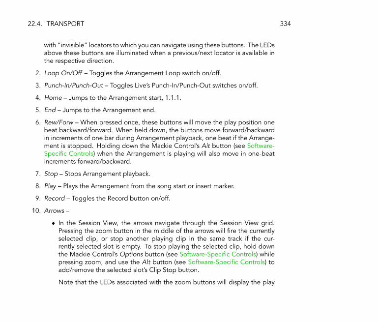
22.4. TRANSPORT 334
with �invisible� locators to which you can navigate using these buttons. The LEDsabove these buttons are illuminated when a previous/next locator is available inthe respective direction.
2. Loop On/Off � Toggles the Arrangement Loop switch on/off.
3. Punch-In/Punch-Out � Toggles Live's Punch-In/Punch-Out switches on/off.
4. Home � Jumps to the Arrangement start, 1.1.1.
5. End � Jumps to the Arrangement end.
6. Rew/Forw � When pressed once, these buttons will move the play position onebeat backward/forward. When held down, the buttons move forward/backwardin increments of one bar during Arrangement playback, one beat if the Arrange-ment is stopped. Holding down the Mackie Control's Alt button (see Software-Speci�c Controls) when the Arrangement is playing will also move in one-beatincrements forward/backward.
7. Stop � Stops Arrangement playback.
8. Play � Plays the Arrangement from the song start or insert marker.
9. Record � Toggles the Record button on/off.
10. Arrows �
� In the Session View, the arrows navigate through the Session View grid.Pressing the zoom button in the middle of the arrows will �re the currentlyselected clip, or stop another playing clip in the same track if the cur-rently selected slot is empty. To stop playing the selected clip, hold downthe Mackie Control's Options button (see Software-Speci�c Controls) whilepressing zoom, and use the Alt button (see Software-Speci�c Controls) toadd/remove the selected slot's Clip Stop button.
Note that the LEDs associated with the zoom buttons will display the play
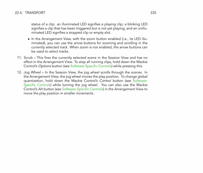
22.4. TRANSPORT 335
status of a clip: an illuminated LED signi�es a playing clip; a blinking LEDsigni�es a clip that has been triggered but is not yet playing; and an unillu-minated LED signi�es a stopped clip or empty slot.
� In the Arrangement View, with the zoom button enabled (i.e., its LED illu-minated), you can use the arrow buttons for zooming and scrolling in thecurrently selected track. When zoom is not enabled, the arrow buttons canbe used to select tracks.
11. Scrub � This �res the currently selected scene in the Session View and has noeffect in the Arrangement View. To stop all running clips, hold down the MackieControl's Options button (see Software-Speci�c Controls) while pressing this.
12. Jog Wheel � In the Session View, the jog wheel scrolls through the scenes. Inthe Arrangement View, the jog wheel moves the play position. To change globalquantization, hold down the Mackie Control's Control button (see Software-Speci�c Controls) while turning the jog wheel. You can also use the MackieControl's Alt button (see Software-Speci�c Controls) in the Arrangement View tomove the play position in smaller increments.
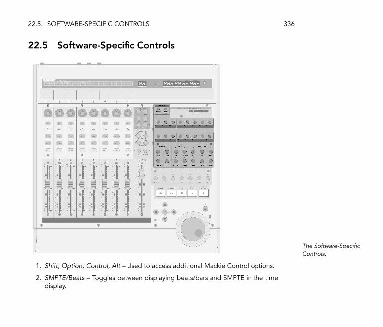
22.5. SOFTWARE-SPECIFIC CONTROLS 336
22.5 Software-Speci�c Controls
The Software-Speci�cControls.
1. Shift, Option, Control, Alt � Used to access additional Mackie Control options.
2. SMPTE/Beats � Toggles between displaying beats/bars and SMPTE in the timedisplay.
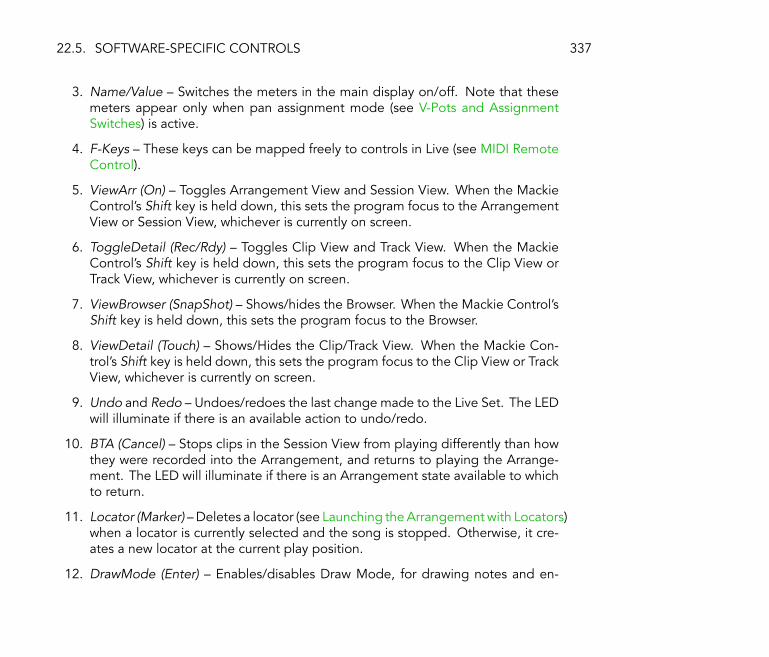
22.5. SOFTWARE-SPECIFIC CONTROLS 337
3. Name/Value � Switches the meters in the main display on/off. Note that thesemeters appear only when pan assignment mode (see V-Pots and AssignmentSwitches) is active.
4. F-Keys � These keys can be mapped freely to controls in Live (see MIDI RemoteControl).
5. ViewArr (On) � Toggles Arrangement View and Session View. When the MackieControl's Shift key is held down, this sets the program focus to the ArrangementView or Session View, whichever is currently on screen.
6. ToggleDetail (Rec/Rdy) � Toggles Clip View and Track View. When the MackieControl's Shift key is held down, this sets the program focus to the Clip View orTrack View, whichever is currently on screen.
7. ViewBrowser (SnapShot) � Shows/hides the Browser. When the Mackie Control'sShift key is held down, this sets the program focus to the Browser.
8. ViewDetail (Touch) � Shows/Hides the Clip/Track View. When the Mackie Con-trol's Shift key is held down, this sets the program focus to the Clip View or TrackView, whichever is currently on screen.
9. Undo and Redo � Undoes/redoes the last change made to the Live Set. The LEDwill illuminate if there is an available action to undo/redo.
10. BTA (Cancel) � Stops clips in the Session View from playing differently than howthey were recorded into the Arrangement, and returns to playing the Arrange-ment. The LED will illuminate if there is an Arrangement state available to whichto return.
11. Locator (Marker) � Deletes a locator (see Launching the Arrangement with Locators)when a locator is currently selected and the song is stopped. Otherwise, it cre-ates a new locator at the current play position.
12. DrawMode (Enter) � Enables/disables Draw Mode, for drawing notes and en-

22.5. SOFTWARE-SPECIFIC CONTROLS 338
velopes.
13. Follow (Mixer) � Toggles Follow Mode, which scrolls Live's display to followplayback.

Chapter 23
Synchronization and ReWire
23.1 Synchronizing via MIDI
The MIDI protocol de�nes two ways to synchronize sequencers, both of which are supportedby Live. Both protocols work with the notion of a sync master, which delivers a sync signalthat is tracked by the sync slave(s).
� MIDI Clock. MIDI Clock works like a metronome ticking at a fast rate. The rate of theincoming ticks is tempo-dependent: Changing the tempo at the sync master (e.g., adrum machine) will cause the slave to follow the change. The MIDI Clock protocol alsoprovides messages that indicate the song position. With respect to MIDI Clock, Livecan act as both a MIDI sync master and slave.
� MIDI Timecode. MIDI Timecode is the MIDI version of the SMPTE protocol, thestandard means of synchronizing tape machines and computers in the audio and�lm industry. A MIDI Timecode message speci�es a time in seconds and frames
339

23.1. SYNCHRONIZING VIA MIDI 340
(subdivisions of a second). Live will interpret a Timecode message as a position in theArrangement. Timecode messages carry no meter-related information; when slavingLive to another sequencer using MIDI Timecode, you will have to adjust the tempomanually. Tempo changes cannot be tracked. Detailed MIDI Timecode preferencesare explained later in this chapter (see MIDI Timecode Options). With respect to MIDITimecode, Live can only act as a MIDI sync slave, not a master.
23.1.1 Synchronizing External MIDI Devices to Live
Live can send MIDI Clock messages to an external MIDI sequencer (or drum machine). Afterconnecting the sequencer to Live and setting it up to receive MIDI sync, turn the device onas a sync destination in Live's MIDI Preferences.
Choosing a MIDI Slavefor Live.
The lower indicator LED next to the Control Bar's EXT button will �ash when Live is sendingsync messages to external sequencers.
23.1.2 Synchronizing Live to External MIDI Devices
Live can be synchronized via MIDI to an external sequencer. After connecting the sequencerto Live and setting it up to send sync, use Live's MIDI Preferences to tell Live about theconnection.

23.1. SYNCHRONIZING VIA MIDI 341
Setting up Live as a MIDISlave.
Then, activate external sync either by switching on the EXT button in the Control Bar orusing the External Sync command in the Options menu. The upper indicator LED next tothe EXT button will �ash if Live receives useable sync messages.
The External SyncSwitch.
When Live is synced to an external MIDI device, it can accept song position pointers fromthis device, syncing it not only in terms of tempo but in terms of its position in the song. Ifthe master jumps to a new position within the song, Live will do the same. However, if theControl Bar's Loop switch is activated, playback will be looped, and song position pointerswill simply be �wrapped� into the length of the loop.
23.1.3 MIDI Timecode Options
Timecode options can be set up per MIDI device. Select a MIDI device from the MIDI/SyncPreferences' Active Device list to access the settings.
The MIDI Timecode Frame Rate setting is relevant only if �MIDI Timecode� is chosen fromthe MIDI Sync Type menu. The MIDI Timecode Rate chooser selects the type of Timecodeto which Live will synchronize. All of the usual SMPTE frame rates are available. When theRate is set to �SMPTE All,� Live will auto-detect the Timecode format of incoming syncmessages and interpret the messages accordingly. Note that you can adjust the Timecode

23.2. CONNECTING VIA REWIRE 342
format that is used for display in the Arrangement View: Go to the Options menu, and thenaccess the Time Ruler Format sub-menu.
The MIDI Timecode Offset setting is also only relevant if �MIDI Timecode� is chosen fromthe Sync Type menu. You can specify a SMPTE time offset using this control. Live willinterpret this value as the Arrangement's start time.
23.1.4 Sync Delay
The Sync Delay controls, which are separately available for each MIDI device, allow you todelay Live's internal time base against the sync signal. This can be useful in compensatingfor delays incurred by the signal transmission. The Sync Delay for a speci�c MIDI deviceappears as you select the MIDI device from the MIDI Preferences' Active Device list. Toadjust the delay, have both Live and the other sequencer play a rhythmical pattern withpronounced percussive sounds. While listening to the output from both, adjust the SyncDelay control until both sounds are in perfect sync.
Adjusting Sync Delay.
23.2 Connecting via ReWire
Live supports the ReWire interface for connecting with another ReWire-compatible audioprogram running on the same computer.

23.2. CONNECTING VIA REWIRE 343
The ReWire technology, developed by Propellerhead Software, provides ReWire-compatibleprograms with:
� common access to the audio hardware;
� shared transport functionality;
� synchronization to audio word clock and song positioning;
� exchange of audio streams.
The programs in a ReWire connection play distinct roles: The ReWire master accesses theaudio hardware and provides mixing facilities; the ReWire slave(s) have no direct link to theaudio hardware, but instead send their audio output into the Master's mixer.
Common ReWire master applications are Digidesign Pro Tools, Steinberg Cubase andNuendo, Emagic Logic Audio, MOTU Digital Performer, Cakewalk Sonar and Cycling 74Max/MSP. Common ReWire slave applications are Propellerheads Rebirth, PropellerheadsReason, Arturia Storm, Cakewalk Project 5 and Cycling 74 Max/MSP. Live can act as both aReWire master and slave.
Note that the ReWire protocol itself does not consume much CPU power. However, asexpected, running two audio-intensive programs on the same computer requires moreresources than running a single program.
23.2.1 Running Live in ReWire Master Mode
The step-by-step procedure for sending MIDI to and receiving audio from a ReWire slaveprogram is presented in the routing chapter (see ReWire Slave Routing).

23.2. CONNECTING VIA REWIRE 344
23.2.2 Running Live in ReWire Slave Mode
If you have not used Live yet, please launch Live so that it can install its ReWire engine inyour system.
Live will run in ReWire slave mode if it detects a running ReWire master application uponstartup. Therefore, always start the ReWire master application �rst, and then start Live.
Likewise, you will �rst have to quit Live, then the ReWire master application.
Live's operation in ReWire slave mode differs from the usual operation in some regards:
� Live will not have direct access to the audio interfaces; audio input/output is handledby the ReWire master application. No audio input will be available to Live.
� The sample rate is determined by the host application rather than by Live.
� External synchronization will be disabled (synchronize to the ReWire master applicationinstead). Live will not send sync or controller messages to the MIDI output. ControllingLive via MIDI is still possible.
� Live will not act as a ReWire master application. For instance, you cannot run Rebirthas a ReWire slave of Live while Live is running as a ReWire slave of Cubase. You can,however, run both Live and Rebirth as ReWire slaves of Cubase at the same time.
23.2.3 More on ReWire
You can �nd tutorials on connecting Live to speci�c ReWire master programs at the Abletontutorial website1.
The Ableton FAQ website2 is the �rst place to go if you encounter ReWire-related problems.
1http://www.ableton.com/tutorials2http://www.ableton.com/faq

23.2. CONNECTING VIA REWIRE 345
If you cannot seem to �nd an answer there, please contact the Ableton support team3.
3http://www.ableton.com/support

Chapter 24
Computer Audio Resources andStrategies
Real-time audio processing is a demanding task for general-purpose computers, which werelikely designed to run spreadsheets and surf the Internet. An application like Live requiresa powerful CPU and a fast hard disk. This section will provide some insight on these issues,and should help you avoid and solve problems with running audio on a computer.
24.1 Managing the CPU Load
To output a continuous stream of sound through the audio hardware, Live has to performa huge number of calculations every second. If the processor can't keep up with whatneeds to be calculated, the audio will have gaps or clicks. Factors that affect computational
346

24.1. MANAGING THE CPU LOAD 347
speed include the processor's clock rate (e.g., speed in MHz or GHz), architecture, memorycache performance (how ef�ciently the processor can grab data from memory) and systembus bandwidth � the computer's �pipeline� through which all data must pass. For thisreason, many people involved with pro audio use computers that are optimized for musicalapplications.
The CPU Load Meter.
The Control Bar's CPU meter displays how much of the processor's computational potential iscurrently being used. For example, if the displayed percentage is 10 percent, the computeris just loa�ng along. If the percentage is 100 percent, the processor is being maxed out � it'slikely that you will hear gaps, clicks or other audio problems. Note that the CPU meter takesinto account only the load from processing audio, not other tasks the computer performs(e.g., managing Live's user interface). Audio calculations have the highest priority in Live.Therefore, even if the CPU shows a high percentage of processor usage, the audio streamshould remain uninterrupted. However, non-critical functions (such as screen redraws) mightslow down because these tasks are handled only when the audio processing �lightens up�a bit.
24.1.1 CPU Load from Multichannel Audio
One source of constant CPU drain is the process of moving data to and from the audiohardware. This drain can be minimized by disabling any inputs and outputs that are notrequired in a project. There are two buttons in the Audio Preferences to access the Inputand Output Con�guration dialogs, which allow activating or deactivating individual ins andouts.
Live does not automatically disable unused channels, because the audio hardware driversusually produce an audible �hiccup� when there is a request for an audio con�guration

24.1. MANAGING THE CPU LOAD 348
change.
24.1.2 CPU Load from Tracks and Devices
Generally, every track and device being used in Live incurs some amount of CPU load.However, Live is �smart� and avoids wasting CPU cycles on tracks and devices that do notcontribute anything useful.
For example, dragging devices into a Live Set that is not running does not signi�cantlyincrease the CPU load. The load increases only as you start playing clips or feed audio intothe effects. When there is no incoming audio, the effects are deactivated until they areneeded again. (If the effect produces a �tail,� like reverbs and delays, deactivation occursonly after all calculations are complete.)
While this scheme is very effective at reducing the average CPU load of a Live Set, it cannotreduce the peak load. To make sure your Live Set plays back continuously, even underthe most intense conditions, play back a clip in every track simultaneously, with all devicesenabled.
24.1.3 Track Freeze
Live's Freeze Track command, available from the Edit menu, can greatly help in managingthe CPU load incurred by devices and clip settings. When you select a track and executethe Freeze command, Live will create a sample �le for each clip in the track, calculating and�freezing� the contribution of devices and clip parameters. Thereafter, clips in the track willsimply play back their freeze samples rather than repeatedly calculating processor-intensivedevice and clip settings in real time.
Most device and clip features in frozen tracks are not accessible. However, launching clipscan still be done freely, and mixer controls such as volume, pan and the sends are still

24.2. MANAGING THE DISK LOAD 349
available. Note that track freeze is not part of Live's Undo history, but executing the Editmenu's Undo command to undo an action that affected a frozen clip will automaticallyunfreeze the respective track.
Once any processor issues have been resolved (or you have upgraded your machine!), youcan always select a frozen track and choose Unfreeze Track from the Edit menu to changedevice or clip settings. On slower machines, you can unfreeze processor-intensive tracksone at a time for editing, freezing them again when you are done.
Besides providing an opportunity to conserve CPU resources on tracks containing a largenumber of devices, the Freeze command simpli�es sharing projects between computers.Computers that are a bit low on processor power can be used to run large Live Sets aslong as any CPU-intensive tracks are frozen. This also means that computers lacking certaindevices used in one Live Set can still play the Set when the relevant device tracks are frozen.
The samples generated by the Track Freeze command are stored in your temporary recordingfolder until you save your Live Set, at which point they are moved to your Sounds folder (seeThe Sounds Folder and Self-Containing).
Note: Frozen Arrangement View tracks will play back any relevant material stretching beyondthe lengths of their clips (e.g., the �tails� on Reverb effects). In the Session View, onlytwo loop cycles are included in the frozen clip, which means that clips with unlinked clipenvelopes (see Unlinking Clip Envelopes From Clips) will play back differently when frozenif those envelopes are longer than two loop cycles.
24.2 Managing the Disk Load
A hard drive's access speed (which is related to, but not identical to, rotational speed) canlimit Live's performance. Most audio-optimized computers use 7200 RPM or faster drives.Laptops, to save power, often use 5400 RPM or slower drives, which is why projects onlaptops usually have lower track counts. The amount of disk traf�c Live generates is roughly

24.2. MANAGING THE DISK LOAD 350
proportional to the number of audio channels being written or read simultaneously. A trackplaying a stereo sample causes more disk traf�c than a track playing a mono sample.
The Disk OverloadIndicator.
The Disk Overload indicator �ashes when the disk was unable to read or write audio quicklyenough. When recording audio, this condition causes a gap in the recorded sample; whenplaying back, you will hear dropouts.
Do the following to avoid disk overload:
� Reduce the amount of audio channels being written by choosing mono inputs insteadof stereo inputs in the Audio Preferences' Channel Con�guration dialog.
� Use RAM Mode (see Clip RAM Mode) for selected clips.
� Reduce the number of audio channels playing by using mono samples instead ofstereo samples when possible. You can convert stereo samples to mono using anystandard digital audio editing program, which can be called up from within Live (seeDestructive Sample Editing).

Chapter 25
Live Keyboard Shortcuts
25.1 Showing and Hiding Views
Windows MacintoshToggle Full Screen Mode F11 Ctrl F11
Toggle Session/Arrangement ViewToggle Track/Clip ViewHide/Show Track/Clip View F12 F12
Double-Click Clip / Track Double-Click Clip / TrackHide/Show Info View ? ?
Hide/Show Overview Ctrl Alt O Alt O
Hide/Show In/Out Ctrl Alt I Alt I
Hide/Show Sends Ctrl Alt S Alt S
351

25.2. ACCESSING MENUS 352
Windows MacintoshHide/Show Mixer Ctrl Alt M Alt M
Hide/Show Crossfader Ctrl Alt F Alt F
Open the Preferences N/A ,
Close the Preferences N/A Esc
25.2 Accessing Menus
Under Windows, you can access each menu by pressing Alt and the �rst letter of themenu ( Alt F for �File�, for instance). While a menu is open, you can use:
� to navigate the menu items;
� to open the neighboring menu;
� Return to choose a menu item.
25.3 Adjusting Values
Windows MacintoshIncrement/DecrementLarge Increment/Decrement Page Page Page Page
Return to Default Delete
Type in Value 0 .. 9 0 .. 9
Go to Next Field (Bar.beat.16th) . , . ,
Abort Value Entry Esc Esc
Con�rm Value Entry Return Return
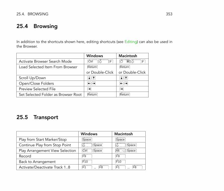
25.4. BROWSING 353
25.4 Browsing
In addition to the shortcuts shown here, editing shortcuts (see Editing) can also be used inthe Browser.
Windows MacintoshActivate Browser Search Mode Ctrl F F
Load Selected Item From Browser Return Return
or Double-Click or Double-ClickScroll Up/DownOpen/Close FoldersPreview Selected FileSet Selected Folder as Browser Root Return Return
25.5 Transport
Windows MacintoshPlay from Start Marker/Stop Space Space
Continue Play from Stop Point Space Space
Play Arrangement View Selection Ctrl Space Alt Space
Record F9 F9
Back to Arrangement F10 F10
Activate/Deactivate Track 1..8 F1 .. F8 F1 .. F8

25.6. EDITING 354
25.6 Editing
Windows MacintoshCut Ctrl X X
Copy Ctrl C C
Paste Ctrl V V
Duplicate Ctrl D D
Delete Delete
Undo Ctrl Z Z
Redo Ctrl Z Z
Rename Ctrl R R
Select All Ctrl A A
By holding down an additional modi�er key, some of the above commands can also beapplied to:
Windows MacintoshClips and Slots Across all TracksTime Across all TracksThe Selected Part of the Envelope Alt Alt
can be used to move from one track or scene to another while renaming.
25.7 Loop Brace and Start/End Markers
The loop brace and start/end markers must �rst be selected before any of the followingcommands will apply to them.
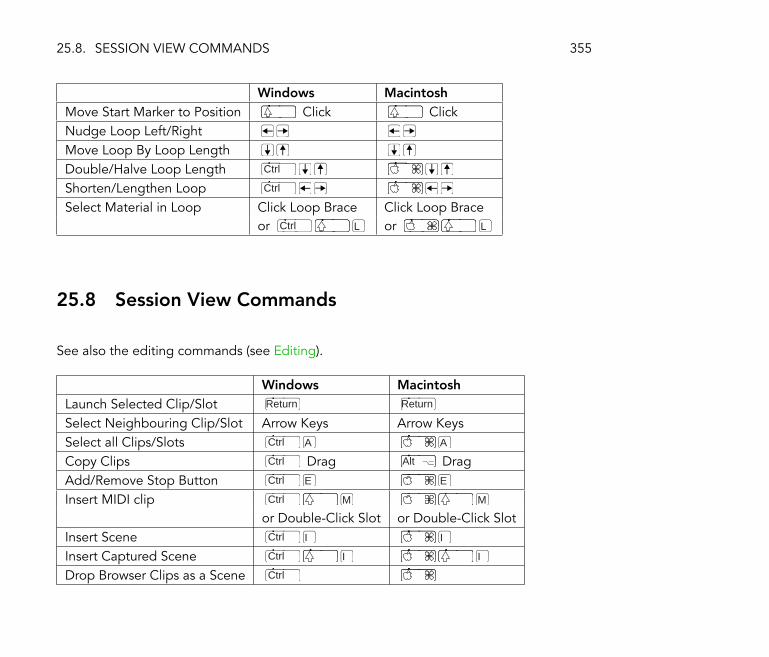
25.8. SESSION VIEW COMMANDS 355
Windows MacintoshMove Start Marker to Position Click ClickNudge Loop Left/RightMove Loop By Loop LengthDouble/Halve Loop Length Ctrl
Shorten/Lengthen Loop Ctrl
Select Material in Loop Click Loop Brace Click Loop Braceor Ctrl L or L
25.8 Session View Commands
See also the editing commands (see Editing).
Windows MacintoshLaunch Selected Clip/Slot Return Return
Select Neighbouring Clip/Slot Arrow Keys Arrow KeysSelect all Clips/Slots Ctrl A A
Copy Clips Ctrl Drag Alt DragAdd/Remove Stop Button Ctrl E E
Insert MIDI clip Ctrl M M
or Double-Click Slot or Double-Click SlotInsert Scene Ctrl I I
Insert Captured Scene Ctrl I I
Drop Browser Clips as a Scene Ctrl
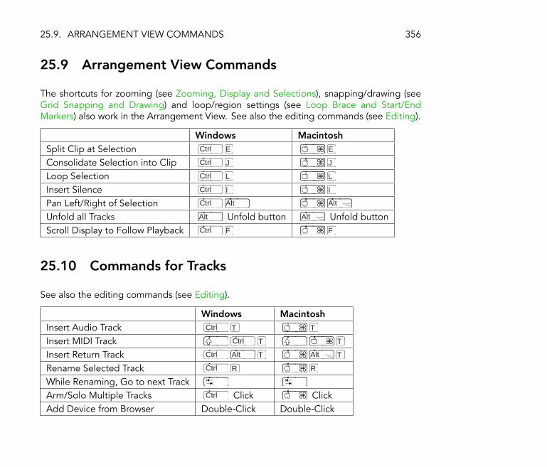
25.9. ARRANGEMENT VIEW COMMANDS 356
25.9 Arrangement View Commands
The shortcuts for zooming (see Zooming, Display and Selections), snapping/drawing (seeGrid Snapping and Drawing) and loop/region settings (see Loop Brace and Start/EndMarkers) also work in the Arrangement View. See also the editing commands (see Editing).
Windows MacintoshSplit Clip at Selection Ctrl E E
Consolidate Selection into Clip Ctrl J J
Loop Selection Ctrl L L
Insert Silence Ctrl I I
Pan Left/Right of Selection Ctrl Alt Alt
Unfold all Tracks Alt Unfold button Alt Unfold buttonScroll Display to Follow Playback Ctrl F F
25.10 Commands for Tracks
See also the editing commands (see Editing).
Windows MacintoshInsert Audio Track Ctrl T T
Insert MIDI Track Ctrl T T
Insert Return Track Ctrl Alt T Alt T
Rename Selected Track Ctrl R R
While Renaming, Go to next TrackArm/Solo Multiple Tracks Ctrl Click ClickAdd Device from Browser Double-Click Double-Click

25.11. COMMANDS FOR BREAKPOINT ENVELOPES 357
25.11 Commands for Breakpoint Envelopes
The shortcuts for zooming (see Zooming, Display and Selections), snapping/drawing (seeGrid Snapping and Drawing) and loop/region settings (see Loop Brace and Start/EndMarkers) also work in the Envelope Editor and Arrangement View. See also the editingcommands (see Editing).
Windows MacintoshFiner Resolution for Dragging Ctrl
Enable Dragging Over Breakpoints
25.12 Key/MIDI Map Mode and the Computer MIDI Key-board
Windows MacintoshToggle MIDI Map Mode Ctrl M M
Toggle Key Map Mode Ctrl K K
Computer MIDI Keyboard Ctrl K K

25.13. ZOOMING, DISPLAY AND SELECTIONS 358
25.13 Zooming, Display and Selections
Windows MacintoshZoom In + +
Zoom Out - -
Drag/Click to Append to a SelectionClick to Add Adjacent Clips to Multi-SelectionClick to Add Nonadjacent Clips to a Multi- Ctrl
SelectionFollow (Auto-Scroll) Ctrl F F
Pan Left/Right of Selection Ctrl Alt Alt
25.14 Clip View Sample Display
The shortcuts for zooming (see Zooming, Display and Selections) and loop/region settings(see Loop Brace and Start/End Markers) also work in the Sample Display.
Windows MacintoshMove Selected Warp MarkerSelect Warp Marker Ctrl
Scroll Display to Follow Playback Ctrl F F
Move Clip Region with Start Marker

25.15. CLIP VIEW MIDI EDITOR 359
25.15 Clip View MIDI Editor
The shortcuts for zooming (see Zooming, Display and Selections), snapping/drawing (seeGrid Snapping and Drawing) and loop/region settings (see Loop Brace and Start/EndMarkers) also work in the MIDI Editor.
Windows MacintoshQuantize Ctrl U U
Scroll Editor Vertically Page Page Page Page
Scroll Editor Horizontally Ctrl Page Page Page Page
Copy Note Ctrl Drag Alt DragChange Velocity From Note Editor Alt Drag DragAdd/Delete Note in Edit Mode Double-Click Double-ClickScroll Display to Follow Playback Ctrl F F
Move Clip Region with Start Marker
25.16 Grid Snapping and Drawing
Windows MacintoshToggle Draw Mode Ctrl B B
Narrow Grid Ctrl 1 1
Widen Grid Ctrl 2 2
Triplet Grid Ctrl 3 3
Snap to Grid Ctrl 4 4
Fixed/Zoom-Adaptive Grid Ctrl 5 5
Bypass Snapping While Dragging Alt

25.17. GLOBAL QUANTIZATION 360
25.17 Global Quantization
Windows MacintoshSixteenth-Note Quantization Ctrl 6 6
Eighth-Note Quantization Ctrl 7 7
Quarter-Note Quantization Ctrl 8 8
1-Bar Quantization Ctrl 9 9
Quantization Off Ctrl 0 0
25.18 Working with Sets and the Program
Windows MacintoshNew Live Set Ctrl N N
Open Live Set Ctrl O O
Close Live Set Ctrl W W
Save Live Set Ctrl S S
Save Live Set As... Ctrl S S
Quit Live Ctrl Q Q
Hide Live N/A H
Render to Disk Ctrl R R
Export MIDI �le Ctrl E E
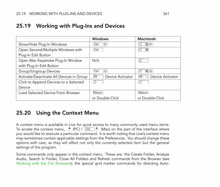
25.19. WORKING WITH PLUG-INS AND DEVICES 361
25.19 Working with Plug-Ins and Devices
Windows MacintoshShow/Hide Plug-In Windows Ctrl P P
Open Second/Multiple Windows with Ctrl
Plug-In Edit ButtonOpen Mac Keystroke Plug-In Window N/Awith Plug-In Edit ButtonGroup/Ungroup Devices Ctrl G G
Activate/Deactivate All Devices in Group Alt Device Activator Alt Device ActivatorClick to Append Devices to a SelectedDeviceLoad Selected Device From Browser Return Return
or Double-Click or Double-Click
25.20 Using the Context Menu
A context menu is available in Live for quick access to many commonly used menu items.To access the context menu, (PC) / Ctrl (Mac) on the part of the interface whereyou would like to execute a particular command. It is worth noting that Live's context menumay sometimes contain applicable settings from the Preferences. You should change theseoptions with care, as they will affect not only the currently selected item but the generalsettings of the program.
Some commands only appear in the context menu. These are: the Create Folder, AnalyzeAudio, Search In Folder, Close All Folders and Refresh commands from the Browser (seeWorking with the File Browsers); the special grid marker commands for directing Auto-

25.20. USING THE CONTEXT MENU 362
Warp (see Syncing Longer Pieces); detailed options for zoom-adaptive and �xed grid linewidth (see Using the Editing Grid); and copying and pasting for Operator's (see Operator)envelopes and oscillators.

Chapter 26
Index
363

Index
A
Abletone-mail addresses
sales. . . . . . . . . . . . . . . . . . . . . . . . . . . . . . . . . . . . . .21technical support . . . . . . . . . . . . . . . . . . . . . . . . . 20
web addressesFAQs. . . . . . . . . . . . . . . . . . . . . . . . . . . . . . . . . . . .344registration . . . . . . . . . . . . . . . . . . . . . . . . . . . . . . . 14tutorials . . . . . . . . . . . . . . . . . . . . . . . . . . . . . . . . . 344unlocking. . . . . . . . . . . . . . . . . . . . . . . . . . . . . . . . .16webshop . . . . . . . . . . . . . . . . . . . . . . . . . . . . . . . . . 19
Active Devices list . . . . . . . . . . . . . . . . . . . . . . . . . . . . . .153Adaptive Grid options . . . . . . . . . . . . . . . . . . . . . . . . . . . 73Add/Remove Stop Button command . . . . . . . . . . . . 84analysis �les . . . . . . . . . . . . . . . . . . . . . . . . . . . . . . . . . . . . . 53
storing clip settings in . . . . . . . . . . . . . . . . . . . . . 105analysis of �les
batch processing . . . . . . . . . . . . . . . . . . . . . . . . . . . 54Analyze Audio command . . . . . . . . . . . . . . . . . . . . . . . . 54Arm Recording button . . . . . . . . . . . . . . . . . . . . 172, 182Arpeggiator effect . . . . . . . . . . . . . . . . . . . . . . . . . . . . . 275
Arrangement . . . . . . . . . . . . . . . see Arrangement ViewArrangement Overview. . . . . . . . . . . . . . . . . . . . . . . . . .65Arrangement Position �elds . . . . . . . . . . . . . . . . . . . . . 67Arrangement View . . . . . . . . . . . . . . . . . . . . . . . . . . . . . . 64
and copying to Session . . . . . . . . . . . . . . . . . . . . . 87and Session View . . . . . . . . . . . . . . . . . . . . . . . . . . . 24grid snapping. . . . . . . . . . . . . . . . . . . . . . . . . . . . . . .73insert marker. . . . . . . . . . . . . . . . . . . . . . . . . . . . . . . .66looping in the. . . . . . . . . . . . . . . . . . . . . . . . . . . . . . .70navigation . . . . . . . . . . . . . . . . . . . . . . . . . . . . . . . . . . 65recording new clips in the . . . . . . . . . . . . . . . . . 183scrub area . . . . . . . . . . . . . . . . . . . . . . . . . . . . . . . . . . 67
Arrangement Viewselector . . . . . . . . . . . . . . . . . . . . . . 24asd �les . . . . . . . . . . . . . . . . . . . . . . . . . . . see analysis �lesaudio clips . . . . . . . . . . . . . . . . . . . . . . . . . . . . . . . . see clipsaudio effects . . . . . . . . . . . . . . . . . . . . . . . . . . . see devicesaudio �les . . . . . . . . . . . . . . . . . . . . . . . . . . . . . see samplesaudio interface setup . . . see Audio Preferences, see
routingAudio Preferences . . . . . . . . . . . . . . . . . . . . . . . . . . . . . . . . 8Audio Record Folder preference . . . . . . . . . . . . . . . 190audio tracks. . . . . . . . . . . . . . . . . . . . . . . . . . . . . .see tracks
364
INDEX 365
Audio Units Plug-ins, using . . . . . . . . . . . . . see devicesauthorization . . . . . . . . . . . . . . . . . . see copy protectionAuto Filter effect . . . . . . . . . . . . . . . . . . . . . . . . . . . . . . . 239Auto Pan effect . . . . . . . . . . . . . . . . . . . . . . . . . . . . . . . . 241Auto-Hide Plug-In Windows option . . . . . . . . . . . . 206Auto-Open Plug-In Windows option . . . . . . . . . . . 206Auto-Warp . . . . . . . . . . . . . . . . . . . . . . . . . . . . . . . . . . . . . 118Auto-Warp Long Samples preference . . . . . . . . . . 123automation. . . . . . . . . . . . . . . . . . . . . . . . . . . . . . . . .39, 215
and grid lines . . . . . . . . . . . . . . . . . . . . . . . . . . . . . .219drawing . . . . . . . . . . . . . . . . . . . . . . . . . . . . . . . . . . . 218editing . . . . . . . . . . . . . . . . . . . . . . . . . . . . . . . . . . . . 219overriding/reactivating . . . . . . . . . . . . . . . . . . . . 216recording . . . . . . . . . . . . . . . . . . . . . . . . . . . . . . . . . . 215
Automation Control chooser . . . . . . . . . . . . . . . . . . . 218Automation Device chooser . . . . . . . . . . . . . . . . . . . . 218
B
Back to Arrangement button . . . . . . . . . . . 27, 86, 216Beat Repeat effect . . . . . . . . . . . . . . . . . . . . . . . . . . . . . 242beat-time ruler
and Arrangement editing . . . . . . . . . . . . . . . . . . . 65and editing envelopes . . . . . . . . . . . . . . . . . . . . . 235and editing MIDI . . . . . . . . . . . . . . . . . . . . . . . . . . 127in the MIDI Editor . . . . . . . . . . . . . . . . . . . . . . . . . 128
Beats Mode . . . . . . . . . . . . . . . . . . . . . . . . . . . . . . . . . . . . 121breakpoint envelopes . . . . . see automation, see clip
envelopesBrowse Presets button . . . . . . . . . . . . . . . . . . . . . . . . . 198Browser . see File Browser, see Live Device Browser,
see Plug-In Device Browser
browsing �les . . . . . . . . . . . . . . . . . . . . . . . . . . . . . . . . . . . 45
C
Capture and Insert Scene command . . . . . . . . . . . . . 85Challenge Code. . . . . . . . . . . . . . . . . . . . . . . . . . . . . . . . . 15Check for Updates command . . . . . . . . . . . . . . . . . . . . . 1Chord effect . . . . . . . . . . . . . . . . . . . . . . . . . . . . . . . . . . . 279Chorus effect . . . . . . . . . . . . . . . . . . . . . . . . . . . . . . . . . . 244Clip Activator switch. . . . . . . . . . . . . . . . . . . . . . . . . . . . .92Clip box . . . . . . . . . . . . . . . . . . . . . . . . . . . . . . . . . . . . . . . . . 90Clip Color chooser . . . . . . . . . . . . . . . . . . . . . . . . . . . . . . 92Clip Envelope Control chooser . . . . . . . . . . . . . . . . . 225Clip Envelope Device chooser. . . . . . . . . . . . . . . . . .224clip envelopes. . . . . . . . . . . . . . . . . . . . . . . . . . . . . .40, 223
and changing note pitch. . . . . . . . . . . . . . . . . . .226and changing note volume . . . . . . . . . . . . . . . . 228as LFOs . . . . . . . . . . . . . . . . . . . . . . . . . . . . . . . . . . . 237changing clips for . . . . . . . . . . . . . . . . . . . . . . . . . 230creating long loops with . . . . . . . . . . . . . . . . . . . 235for MIDI controls . . . . . . . . . . . . . . . . . . . . . . . . . . 233general editing of . . . . . . . . . . . . . . . . . . . . . . . . . 224imposing rhythm with. . . . . . . . . . . . . . . . . . . . . .236loop/region settings for. . . . . . . . . . . . . . . . . . . .234mixer control modulation with . . . . . . . . . . . . . 231scrambling beats with . . . . . . . . . . . . . . . . . . . . . 229unlinking from clips . . . . . . . . . . . . . . . . . . . . . . . . 234using for fade-outs . . . . . . . . . . . . . . . . . . . . . . . . 234
Clip Fade switch . . . . . . . . . . . . . . . . . . . . . . . . . . . . . . . 106Clip Gain slider . . . . . . . . . . . . . . . . . . . . . . . . . . . . . . . . 103Clip Groove chooser . . . . . . . . . . . . . . . . . . . . . . . . . . . . 93

INDEX 366
Clip Launch button . . . . . . . . . . . . . . . . . . . . . . . . . . . . . . 79Clip Name �eld . . . . . . . . . . . . . . . . . . . . . . . . . . . . . . . . . 92Clip Nudge buttons . . . . . . . . . . . . . . . . . . . . . . . . . . . . . 94Clip Overview . . . . . . . . . . . . . . . . . . . . . . . . . . . . . . . . . . . 88
for zooming/scrolling . . . . . . . . . . . . . . . . . . . . . . . 98Clip Quantization chooser . . . . . . . . . . . . . . . . . . . . . .141Clip Record button . . . . . . . . . . . . . . . . . . . . . . . . . 38, 185Clip Signature �elds . . . . . . . . . . . . . . . . . . . . . . . . . . . . . 93Clip Stop button . . . . . . . . . . . . . . . . . . . . . . . . . . . . . . . . 79
adding/removing . . . . . . . . . . . . . . . . . . . . . . . . . . . 84Clip Update Rate preference . . . . . . . . . . . . . . . . . . . 110Clip View. . . . . . . . . . . . . . . . . . . . . . . . . . . . . . . . . . . . . . . .88
and playing the Arrangement . . . . . . . . . . . . . . . 68and remote-control mapping . . . . . . . . . . . . . . 323scrub area . . . . . . . . . . . . . . . . . . . . . . . . . . . . . . . . . 100
Clip View boxes selector . . . . . . . . . 91, 125, 139, 224clips . . . . . . . . . . . . . . . . . . . . . . . . . . . . . . . . . . . . . . . . . . . . . 24
adding fades to . . . . . . . . . . . . . . . . . . . . . . . . . . . 106arranging/editing . . . . . . . . . . . . . . . . . . . . . . . . . . . 71as templates. . . . . . . . . . . . . . . . . . . . . . . . . . . . . . .230audio clips . . . . . . . . . . . . . . . . . . . . . . . . . . . . . . . . . . 28clip multi-selections . . . . . . . . . . . . . . . . . . . . . . . . .89deactivating/muting . . . . . . . . . . . . . . . . . . . . . . . . 92editing MIDI notes/velocities . . . . . . . . . . . . . . 124importing from �les . . . . . . . . . . . . . . . . . . . . . . . . . 50in Arrangement View . . . . . . . . . . . . . . . . . . . . . . . 71in audio/MIDI tracks . . . . . . . . . . . . . . . . . . . . . . . . 27in Session View . . . . . . . . . . . . . . . . . . . . . . . . . . . . . 79Live Clips . . . . . . . . . . . . . . . . . . . . . . . . . . . . . . . . . . . 58managing meter offset . . . . . . . . . . . . . . . . . . . . . .95MIDI clips . . . . . . . . . . . . . . . . . . . . . . . . . . . . . . . . . . .30
renaming . . . . . . . . . . . . . . . . . . . . . . . . . . . . . . . . . . . 92reversing . . . . . . . . . . . . . . . . . . . . . . . . . . . . . . . . . . 108saving settings for . . . . . . . . . . . . . . . . . . . . . . . . . 105setting properties of . . . . . . . . . . . . . . . . . . . . . . . . 88
Close All Folders command . . . . . . . . . . . . . . . . 47, 198Complex Mode . . . . . . . . . . . . . . . . . . . . . . . . . . . . . . . . 123compressed audio �les . . . . . . . . . . . . . . . . see samplesCompressor I effect . . . . . . . . . . . . . . . . . . . . . . . . . . . . 246Compressor II effect. . . . . . . . . . . . . . . . . . . . . . . . . . . .248Computer MIDI Keyboard button . . . . . . . . . . . . . . 154Computer MIDI Keyboard option . . . . . . . . . . . . . . 154Consolidate command . . . . . . . . . . . . . . . . . . . . . . . . . . 76context menu . . . . . . . . . . . . . . . . . . . . . . . . . . . . . . . . . . 361Control chooser . . see Automation Control chooser,
see Clip Envelope Control choosercontrol surfaces . . . . . . . . . . . . . . . . see Mackie ControlCopy Envelope command. . . . . . . . . . . . . . . . . . . . . .221copy protection . . . . . . . . . . . . . . . . . . . . . . . . . . . . . . . . . 12count-in for recording . . . . . . . . . . . . . . . . . . . . . . . . . . 189Count-In setting. . . . . . . . . . . . . . . . . . . . . . . . . . . . . . . .189CPU. . . . . . . . . . . . . . . . . . . . . . . . . . . . . . . . . . . . . . . . . . . .346CPULoadmeter. . . . . . . . . . . . . . . . . . . . . . . . . . . . . . . . .347Create Analysis Files preference . . . . . . . . . . . . . . . . . 54Create Folder command. . . . . . . . . . . . . . . . . . . . . . . . .51crossfader . . . . . . . . . . . . . . . . . . . . . . . . . . . . . . . . . . 34, 175
and remote control . . . . . . . . . . . . . . . . . . . . . . . . 175automating the . . . . . . . . . . . . . . . . . . . . . . . . . . . . 176
Cue Out chooser . . . . . . . . . . . . . . . . . . . . . . . . . . . . . . .177cue points . . . . . . . . . . . . . . . . . . . . . . . . . . . . . see locatorscueing . . . . . . . . . . . . . . . . . . . . . . . . . . . . . . . . . . . . . . . . . 177Cut Envelope command . . . . . . . . . . . . . . . . . . . . . . . 221

INDEX 367
Cut Scenes command . . . . . . . . . . . . . . . . . . . . . . . . . . . 84Cut Time command . . . . . . . . . . . . . . . . . . . . . . . . . . . . . 74
D
Decoding Cache preferences . . . . . . . . . . . . . . . . . . . . 52Default Preferences . . . . . . . . . . . . . . . . . . . . . . . . . . . . . . . 9
and recording clips . . . . . . . . . . . . . . . . . . . . . . . . 190for clip settings . . . . . . . . . . . . . . . . . . . . . . . . . . . . 110
Delay Compensation option . . . . . . . . . . . . . . . . . . . 214Delete Automation command . . . . . . . . . . . . . . . . . . 216Delete command
and devices . . . . . . . . . . . . . . . . . . . . . . . . . . . . . . . 196and envelopes. . . . . . . . . . . . . . . . . . . . . . . . . . . . .225and key mapping . . . . . . . . . . . . . . . . . . . . . . . . . . 316and MIDI mapping . . . . . . . . . . . . . . . . . . . . . . . . 319and tracks . . . . . . . . . . . . . . . . . . . . . . . . . . . . . . . . . 173in the Browser . . . . . . . . . . . . . . . . . . . . . . . . . . . . . . 51
Delete Locator button . . . . . . . . . . . . . . . . . . . . . . . . . . . 69Delete Locator command . . . . . . . . . . . . . . . . . . . . . . . 69Delete Scenes command . . . . . . . . . . . . . . . . . . . . . . . . 85Delete Time command . . . . . . . . . . . . . . . . . . . . . . . . . . 75Demo Mode . . . . . . . . . . . . . . . . . . . . . . . . . . . . . . . . . . . . 18Demo Sets . . . . . . . . . . . . . . . . . . . . . . . . . . . . . . . . . . . . . . 23Detune �eld . . . . . . . . . . . . . . . . . . . . . . . . . . . . . . . . . . . 103Device Activator switch . . . . . . . . . . . . . . . . . . . . . . . . 196Device chooser . . . see Automation Device chooser,
see Clip Envelope Device chooserdevices. . . . . . . . . . . . . . . . . . . . . . . . . . . . . . . . . . . . . . . . . .31
compensating for delays. . . . . . . . . . . . . . . . . . .214device groups . . . . . . . . . . . . . . . . . . . . . . . . . . . . . 201
presets . . . . . . . . . . . . . . . . . . . . . . . . . . . . . . . . . . . . 197the Live audio effects . . . . . . . . . . . . . . . . . . . . . . 238the Live instruments . . . . . . . . . . . . . . . . . . . . . . . 285the Live MIDI effects . . . . . . . . . . . . . . . . . . . . . . .274using Audio Units Plug-ins . . . . . . . . . . . . . . . . . 212using Live devices . . . . . . . . . . . . . . . . . . . . . . . . . 194using plug-in devices . . . . . . . . . . . . . . . . . . . . . . 202using VST Plug-ins . . . . . . . . . . . . . . . . . . . . . . . . . 207
Double/Halve Original BPM buttons . . . . . . 109, 115Draw Mode . . . . . . . . . . . . . . . . . . . . . . . . . . . . . . . . . . . . 218
and drawing MIDI . . . . . . . . . . . . . . . . . . . . . . . . . 126with clip envelopes . . . . . . . . . . . . . . . . . . . . . . . . 226
Draw Modecommand . . . . . . . . . . . . . . . . . . . . . . . . . . 218Duplicate Envelope command . . . . . . . . . . . . . . . . . 221Duplicate Scenes command . . . . . . . . . . . . . . . . . . . . . 85Duplicate Time command . . . . . . . . . . . . . . . . . . . . . . . 75
E
Edit menu commandsand automation . . . . . . . . . . . . . . . . . . . . . . 216, 221and MIDI notes . . . . . . . . . . . . . . . . . . . . . . . . . . . . 133and rendering to disk . . . . . . . . . . . . . . . . . . . . . . . 56and return tracks . . . . . . . . . . . . . . . . . . . . . . . . . . 174and scenes . . . . . . . . . . . . . . . . . . . . . . . . . . . . . . . . . 81and tracks . . . . . . . . . . . . . . . . . . . . . . . . . . . . . . . . . 173in the Browser . . . . . . . . . . . . . . . . . . . . . . . . . . . . . . 50with Clip Stop buttons . . . . . . . . . . . . . . . . . . . . . . 84with clips . . . . . . . . . . . . . . . . . . . . . . . . . . . . . . . . . . . 92with scenes . . . . . . . . . . . . . . . . . . . . . . . . . . . . . . . . . 84
effects . . . . . . . . . . . . . . . . . . . . . . . . . . . . . . . . . see devices

INDEX 368
Envelope Editor . . . . . . . . . . . . . . . . . . . . . . . . . . . . 90, 224envelopes . . . . . .see automation, see clip envelopesEnvelopes box . . . . . . . . . . . . . . . . . . . . . . . . . . . . . 90, 224EQ Four effect . . . . . . . . . . . . . . . . . . . . . . . . . . . . . . . . . 251EQ Three effect . . . . . . . . . . . . . . . . . . . . . . . . . . . . . . . . 250Erosion effect . . . . . . . . . . . . . . . . . . . . . . . . . . . . . . . . . . 252Exclusive Arm option. . . . . . . . . . . . . . . . . . . . . . . . . . .172Exclusive Solo option . . . . . . . . . . . . . . . . . . . . . . . . . . 172Exit Search button . . . . . . . . . . . . . . . . . . . . . . . . . . . . . . .48Export MIDI Clip command. . . . . . . . . . . . . . . . . . . . . .58exporting audio. . . . . . . . . . . . . . . . .see Render to Diskexternal sync . . . . . . . . . . . . . see MIDI synchronization
F
FAQs . . . . . . . . . . . . . . . . . . . . . . . . . . . . . . . . . . see AbletonFile Browser . . . . . . . . . . . . . . . . . . . . . . . . . . . . . . . . . . . . . 45
opening Sets with the. . . . . . . . . . . . . . . . . . . . . . .23Filter Delay effect . . . . . . . . . . . . . . . . . . . . . . . . . . . . . . 253Fixed Grid command . . . . . . . . . . . . . . . . . . . . . . . . . . . . 74Fixed Grid options . . . . . . . . . . . . . . . . . . . . . . . . . . . . . . 73FLAC �les . . . . . . . . . . . . . . . . . . . . . . . . . . . . . see samplesFlanger effect . . . . . . . . . . . . . . . . . . . . . . . . . . . . . . . . . . 255Fold button . . . . . . . . . . . . . . . . . . . . . . . . . . . . . . . . . . . . 130Folder-Up button . . . . . . . . . . . . . . . . . . . . . . . . . . . . . . . . 46Follow Actions . . . . . . . . . . . . . . . . . . . . . . . . . . . . . . . . . 143Follow command . . . . . . . . . . . . . . . . . . . . . . . . . . . . 66, 99Follow switch . . . . . . . . . . . . . . . . . . . . . . 66, 99, 113, 129Freeze Track command. . . . . . . . . . . . . . . . . . . . . . . . .348freezing tracks . . . . . . . . . . . . . . . . . . . . . . . . . . . . . . . . . 348
G
Gate effect . . . . . . . . . . . . . . . . . . . . . . . . . . . . . . . . . . . . .256Gate Mode . . . . . . . . . . . . . . . . . . . . . . . . . . . . . . . . . . . . 140Global Quantization chooser . . . . . . . . . . . . . . . . . . . . 38
and Session recording . . . . . . . . . . . . . . . . . . . . . 184Grain Delay effect . . . . . . . . . . . . . . . . . . . . . . . . . . . . . . 258Grain Flux �eld. . . . . . . . . . . . . . . . . . . . . . . . . . . . . . . . .122Grain Size �eld . . . . . . . . . . . . . . . . . . . . . . . . . . . . . . . . . 122Grain Size knob . . . . . . . . . . . . . . . . . . . . . . . . . . . . . . . . 122grid
and Arrangement editing . . . . . . . . . . . . . . . . . . . 73and envelope drawing . . . . . . . . . . . . . . . . . . . . . 219and MIDI editing . . . . . . . . . . . . . . . . . . . . . . . . . . 131in editing clip envelopes. . . . . . . . . . . . . . . . . . .236working with the . . . . . . . . . . . . . . . . . . . . . . . . . . . . 73
groove feature . . . . . . . . . . . . . . . . . . . . . . . . . . . . . . . . . . 93Group Devices command . . . . . . . . . . . . . . . . . . . . . . 201
H
hard disk . . . . . . . . . . . . . . . . . . . . . . . . . . . . . . . . . . see CPUHard Disk Overload indicator. . . . . . . . . . . . . . . . . . .350hiding products . . . . . . . . . . . . . . . . . . . . . . . . . . . . . . . . . 21High Quality switch . . . . . . . . . . . . . . . . . . . . . . . . . . . . 106
I
I/O . . . . . . . . . . . . . . . . . . . . . . . . . . . . . . . . . . . . . see routingimporting �les . . . . . . . . . . . . . . . . . . . . . . . . . . . . . . . . . . .50Impulse instrument. . . . . . . . . . . . . . . . . . . . . . . . . . . . .286
and individual outputs . . . . . . . . . . . . . . . . . . . . . 289
INDEX 369
and MIDI . . . . . . . . . . . . . . . . . . . . . . . . . . . . . . . . . . 286�lter . . . . . . . . . . . . . . . . . . . . . . . . . . . . . . . . . . . . . . . 288global parameters . . . . . . . . . . . . . . . . . . . . . . . . . 289Link button . . . . . . . . . . . . . . . . . . . . . . . . . . . . . . . . 287pan and volume . . . . . . . . . . . . . . . . . . . . . . . . . . . 288sample slots and controls . . . . . . . . . . . . . . . . . . 286saturator and envelope . . . . . . . . . . . . . . . . . . . . 288Start, Tune and Stretch . . . . . . . . . . . . . . . . . . . . 287
Info View . . . . . . . . . . . . . . . . . . . . . . . . . . . . . . . . . . . . . . . . . 7insert
effect . . . . . . . . . . . . . . . . . . . . . . . . . . . . . . . . . . . . . . 194instrument . . . . . . . . . . . . . . . . . . . . . . . . . . . . . . . . .194plug-ins . . . . . . . . . . . . . . . . . . . . . . . . . . . . . . . . . . . 202track. . . . . . . . . . . . . . . . . . . . . . . . . . . . . . . . . . . . . . .172
Insert Audio Track command . . . . . . . . . . . . . . . . . . . 172insert marker . . . . . . . . . . . . . . . . . . . . . . . . . . . . . . . . . . . . 66Insert MIDI Clip command . . . . . . . . . . . . . . . . . . . . . 124Insert MIDI Track command . . . . . . . . . . . . . . . . . . . . 172Insert Return Track command . . . . . . . . . . . . . . . . . . 174Insert Scene command . . . . . . . . . . . . . . . . . . . . . . . . . . 85Insert Silence command . . . . . . . . . . . . . . . . . . . . . . . . . 75instruments . . . . . . . . . . . . . . . . . . . . . . . . . . . . see devices
K
Keep Offset button. . . . . . . . . . . . . . . . . . . . . . . . . . . . . .95Key Map Mode switch . . . . . . . . . . . . . . . . . . . . . . . . . 316Key/MIDI In Indicator . . . . . . . . . . . . . . . . . . . . . . . . . . 156Key/MIDI Out Indicator . . . . . . . . . . . . . . . . . . . . . . . . 156keyboard shortcuts . . . . . . . . . . . . . . . . . . . . . . . . . . . . . 351
L
latency . . . . . . . . . . . . . . . . . . . . . . see Sync Delay settingLaunch box. . . . . . . . . . . . . . . . . . . . . . . . . . . . . . . . .90, 139Launch Modes . . . . . . . . . . . . . . . . . . . . . . . . . . . . . . . . . 140Launch Sample Editor button . . . . . . . . . . . . . . . . . . 103Legato Mode . . . . . . . . . . . . . . . . . . . . . . . . . . . . . . . . . . 142lessons . . . . . . . . . . . . . . . . . . . . . . . . . . . . . . . . . . . . . . . . . . . 7library . . . . . . . . . . . . . . . . . . . . . . . . . . . . . . . . . . . . . . . . . . . 44Link/Unlink Envelope switch . . . . . . . . . . . . . . . . . . . . 234Live Clips. . . . . . . . . . . . . . . . . . . . . . . . . . . . . . . . . . . . . . . .58Live Device Browser. . . . . . . . . . . . . . . . . . . . . . . . . . . .194Live Packs . . . . . . . . . . . . . . . . . . . . . . . . . . . . . . . . . . . . . . . 63Locate In Browser button . . . . . . . . . . . . . . . . . . . . . . . . 48locators . . . . . . . . . . . . . . . . . . . . . . . . . . . . . . . . . . . . . . . . . 68Lock Envelopes command . . . . . . . . . . . . . . . . . . . . . 220Lock Envelopes switch . . . . . . . . . . . . . . . . . . . . . . . . . 220loop brace
in the Arrangement . . . . . . . . . . . . . . . . . . . . . . . . . 70with clips . . . . . . . . . . . . . . . . . . . . . . . . . . . . . . . . . . 101
Loop Selection command . . . . . . . . . . . . . . . . . . . . . . . 70Loop Start/Punch-In Position �elds . . . . . . . . . . . . . . 70Loop switch
Clip View . . . . . . . . . . . . . . . . . . . . . . . . . . . . . 101, 235Control Bar . . . . . . . . . . . . . . . . . . . . . . . . . . . . . . . . . 70with MIDI clips. . . . . . . . . . . . . . . . . . . . . . . . . . . . .131
Loop To Next Locator command . . . . . . . . . . . . . . . . 69Loop/Punch Region Length �elds . . . . . . . . . . . . . . . 70Loop/Region controls . . . . . . . . . . . . . . . . . . . . . . 99, 101
and clip envelopes . . . . . . . . . . . . . . . . . . . . . . . . 234with MIDI clips. . . . . . . . . . . . . . . . . . . . . . . . . . . . .131

INDEX 370
Loop/Warp Short Samples preference . . . . . . . . . . 123
M
Mackie Control . . . . . . . . . . . . . . . . . . . . . . . . . . . . . . . . .324mapping to MIDI/keys. . . . . . . . . . . . . . . . . . . . . .41, 317
and recording . . . . . . . . . . . . . . . . . . . . . . . . . . . . . 190Master Out chooser . . . . . . . . . . . . . . . . . . . . . . . . . . . . 177Master track. . . . . . . . . . . . . . . . . . . . . . . . . . . . . . . . . . . .173Metronome switch . . . . . . . . . . . . . . . . . . . . . . . . . . . . . 187MIDI
exporting . . . . . . . . . . . . . . . . . . . . . . . . . . . . . . . . . . . 58quantizing . . . . . . . . . . . . . . . . . . . . . . . . . . . . 132, 188sending bank/program changes . . . . . . . . . . . 109
MIDI clips . . . . . . . . . . . . . . . . . . . . . . . . . . . . . . . . . see clipsMIDI controllers . . . . . . . . . . . . . . . . see Mackie ControlMIDI controllers/messages . . . . . . . . . . . . . . . . . . . . . 319MIDI Editor. . . . . . . . . . . . . . . . . . . . . . . . . . . . . . . . .90, 124
and drawing MIDI . . . . . . . . . . . . . . . . . . . . . . . . . 126and drawing velocities . . . . . . . . . . . . . . . . . . . . . 136and grid lines. . . . . . . . . . . . . . . . . . . . . . . . .131, 135and recording MIDI . . . . . . . . . . . . . . . . . . . . . . . . 186creating and editing notes . . . . . . . . . . . . . . . . . 133editing velocities . . . . . . . . . . . . . . . . . . . . . . . . . . 136loop/region settings for. . . . . . . . . . . . . . . . . . . .131navigation . . . . . . . . . . . . . . . . . . . . . . . . . . . . . . . . . 127rearranging notes in . . . . . . . . . . . . . . . . . . . . . . . 132
MIDI effects . . . . . . . . . . . . . . . . . . . . . . . . . . . . see devicesMIDI �les . . . . . . . . . . . . . . . . . . . . . . . . . . . . . . . . . . . . . . . . 30MIDI implementation . . . . . . . . . . . . . . . . . . . . . . . . . . 319MIDI interface setup . . . . . . . . . . . . . . . . . . . . see routing
MIDI Map Mode switch . . . . . . . . . . . . . . . . . . . . . . . . 318MIDI Preferences . . . . . . . . . . . . . . . . . . . . . . . . . . . . . . . . . 9MIDI synchronization . . . . . . . . . . . . . . . . . . . . . . . . . . . 339MIDI Timecode Frame Rate preference. . . . . . . . .341MIDI Timecode Start Offset preference. . . . . . . . .342MIDI Track In Indicator . . . . . . . . . . . . . . . . . . . . . . . . . 156MIDI Track Out Indicator . . . . . . . . . . . . . . . . . . . . . . . 156MIDI tracks . . . . . . . . . . . . . . . . . . . . . . . . . . . . . . see tracksMisc Preferences . . . . . . . . . . . . . . . . . . . . . . . . . . . . . . . . . 9mixer. . . . . . . . . . . . . . . . . . . . . . . . . . . . . . . . . . . . . . .33, 169Mixer Section selector. . . . . . . . . . . . . . . . . . . . . . . . . .171modulation . . . . . . . . . . . . . . . . . . . . . see clip envelopesmonitor mix . . . . . . . . . . . . . . . . . . . . . . . . . . . . . . . . . . . . 174monitoring . . . . . . . . . . . . . . . . . . . . . . . . . . . . . . . . . . . . . 150monitoring through Live . . . . .see Audio PreferencesMP3 �les . . . . . . . . . . . . . . . . . . . . . . . . . . . . . . see samplesMultiple Plug-In Windows option. . . . . . . . . . . . . . .206muting. . . . . . . . . . . . . . . . . . .see Track Activator switch
clips . . . . . . . . . . . . . . . . . . . . . . . . . . . . . . . . . . . . . . . . 92
N
Narrow Grid command . . . . . . . . . . . . . . . . . . . . . . . . . . 73New command . . . . . . . . . . . . . . . . . . . . . . . . . . . . . . . . . . 59Next Locator button . . . . . . . . . . . . . . . . . . . . . . . . . . . . . 69normalizing rendered audio . . . . . . . . . . . . . . . . . . . . . 56Note Editor . . . . . . . . . . . . . . . . . . . . . . . . . . . . . . . . . . . . 125Notes box . . . . . . . . . . . . . . . . . . . . . . . . . . . . . . . . . . . . . . .91Nudge buttons . . . . . . . . . . . . see Clip Nudge buttons

INDEX 371
O
of�ine clips . . . . . . . . . . . . . . . . . . . . . . . . . . . . . . . . . . . . . . 62Ogg �les . . . . . . . . . . . . . . . . . . . . . . . . . . . . . . see samplesOpen/Open Recent command . . . . . . . . . . . . . . . . . . 59Operator instrument . . . . . . . . . . . . . . . . . . . . . . . . . . . 295
algorithms . . . . . . . . . . . . . . . . . . . . . . . . . . . . . . . . . 297aliasing and Tone . . . . . . . . . . . . . . . . . . . . . . . . . . 299and CPU resources . . . . . . . . . . . . . . . . . . . . . . . . 307envelopes . . . . . . . . . . . . . . . . . . . . . . . . . . . . . . . . . 302�lter . . . . . . . . . . . . . . . . . . . . . . . . . . . . . . . . . . . . . . . 304Glide and Spread. . . . . . . . . . . . . . . . . . . . . . . . . .306global controls . . . . . . . . . . . . . . . . . . . . . . . . . . . . 304layout . . . . . . . . . . . . . . . . . . . . . . . . . . . . . . . . . . . . . 296LFO . . . . . . . . . . . . . . . . . . . . . . . . . . . . . . . . . . . . . . . 301oscillators . . . . . . . . . . . . . . . . . . . . . . . . . . . . . . . . . 298parameter list. . . . . . . . . . . . . . . . . . . . . . . . . . . . . .307purchasing . . . . . . . . . . . . . . . . . . . . . . . . . . . . . . . . 296unlocking . . . . . . . . . . . . . . . . . . . . . . . . . . . . . . . . . . . 12
Original BPM �eld . . . . . . . . . . . . . . . . . . . . . . . . 109, 115Overdub Switch . . . . . . . . . . . . . . . . . . . . . . . . . . . 184, 186Overdubbing . . . . . . . . . . . . . . . . . . . . . . . . . . . . . . . . . . 186
P
Pan control. . . . . . . . . . . . . . . . . . . . . . . . . . . . . . . . . . . . .172Pan quick-chooser button . . . . . . . see quick-chooser
buttonsPaste Scenes command . . . . . . . . . . . . . . . . . . . . . . . . . 85Paste Time command . . . . . . . . . . . . . . . . . . . . . . . . . . . 74pencil tool . . . . . . . . . . . . . . . . . . . . . . . . . see Draw ModePhaser effect . . . . . . . . . . . . . . . . . . . . . . . . . . . . . . . . . . . 260
Ping Pong Delay effect . . . . . . . . . . . . . . . . . . . . . . . . . 261Pitch Bend quick-chooser button see quick-chooser
buttonsPitch effect . . . . . . . . . . . . . . . . . . . . . . . . . . . . . . . . . . . . .280Play button . . . . . . . . . . . . . . . . . . . . . . . . . . . . . . . . . . . . . . 66Plug-In Device Browser. . . . . . . . . . . . . . . . . . . . . . . . .203Plug-In Device Browserselector. . . . . . . . . . . . . . . . .203Plug-In Edit button . . . . . . . . . . . . . . . . . . . . . . . . . . . . . 206Plug-In Performance setting . . . . . . . . . . . . . . . . . . . . 207Plug-In Preferences . . . . . . . . . . . . . . . . . . . . . . . . . . 9, 207Plug-In Unfold button . . . . . . . . . . . . . . . . . . . . . . . . . . 204plug-ins, using . . . . . . . . . . . . . . . . . . . . . . . . . see devicespre-listening samples . . . . . . . . . . . . . . . see previewingPre/Post switches . . . . . . . . . . . . . . . . . . . . . . . . . . . . . . 174Preferences . . . . . . . . . . . . . . . . . . . . . . . . . . . . . . . . . . . . . . . 8Preset Save button . . . . . . . . . . . . . . . . . . . . . . . . . . . . . 199Preview switch . . . . . . . . . . . . . . . . . . . . . . . . 49, 126, 127Preview Volume knob . . . . . . . . . . . . . . . . . . . . . . . . . . 187previewing
in the Browser . . . . . . . . . . . . . . . . . . . . . . . . . . . . . . 49in the MIDI Editor . . . . . . . . . . . . . . . . . . . . . . . . . 126
Previous Locator button . . . . . . . . . . . . . . . . . . . . . . . . . 69processor . . . . . . . . . . . . . . . . . . . . . . . . . . . . . . . . . see CPUProducts Preferences . . . . . . . . . . . . . . . . . . . . . . . . . 9, 12
and Live Packs . . . . . . . . . . . . . . . . . . . . . . . . . . . . . . 63Punch-In/Out switches . . . . . . . . . . . . . . . . . . . . . . . . . 184
Q
quantizationcommand for selected MIDI notes . . . . . . . . . 132

INDEX 372
for clip launching . . . . . . . . . . . . . . . . . . . . . . . . . . 141for MIDI notes during recording . . . . . . . . . . . 188
Quantize menu command. . . . . . . . . . . . . . . . . . . . . . 132quick-chooser buttons . . . . . . . . . . . . . . . . . . . . . . . . . 225
R
RAM Mode switch. . . . . . . . . . . . . . . . . . . . . . . . . . . . . .107Random effect . . . . . . . . . . . . . . . . . . . . . . . . . . . . . . . . . 281Re-Pitch Mode . . . . . . . . . . . . . . . . . . . . . . . . . . . . . . . . . 122Re-Scan Plug-Ins preference. . . . . . . . . . . . . . . . . . . .203Record Bit Depth preference . . . . . . . . . . . . . . . . . . . 190Record button . . . . . . . . . . . . . . . . . . . . . . . . . . . . . . . . . . .85Record File Type preference. . . . . . . . . . . . . . . . . . . .190Record Quantization . . . . . . . . . . . . . . . . . . . . . . . . . . . 188recording
and remote control . . . . . . . . . . . . . . . . . . . . . . . . 190audio and MIDI . . . . . . . . . . . . . . . . . . . . . . . . . . . . 180automation . . . . . . . . . . . . . . . . . . . . . . . . . . . . . . . . 215overdubbing . . . . . . . . . . . . . . . . . . . . . . . . . 183, 186punch-in/punch-out . . . . . . . . . . . . . . . . . . . . . . . 183resampling the Master output . . . . . . . . . . . . . 158with count-in . . . . . . . . . . . . . . . . . . . . . . . . . . . . . . 189
recording an Arrangement . . . . . . . . . . . . . . . . . . . . . . 85recording automation . . . . . . . . . . . . . . . . . . . . . . . . . . 215Redux effect . . . . . . . . . . . . . . . . . . . . . . . . . . . . . . . . . . . 266Refresh command . . . . . . . . . . . . . . . . . . . . . . . . . . . . . . . 47registration . . . . . . . . . . . . . . . . . . . . . . . . . . . . see Abletonremote control . . . . . . . . . . see mapping to MIDI/keysRemote Control Surfaces settings . . . . . . . . . . . . . . 324Rename command
in the Browser . . . . . . . . . . . . . . . . . . . . . . . . . . . . . . 51with clips . . . . . . . . . . . . . . . . . . . . . . . . . . . . . . . . . . . 92with locators . . . . . . . . . . . . . . . . . . . . . . . . . . . . . . . . 69with plug-ins . . . . . . . . . . . . . . . . . . . . . . . . . . . . . . 211
Render to Disk . . . . . . . . . . . . . . . . . . . . . . . . . . . . . . . . . . 55Repeat Mode . . . . . . . . . . . . . . . . . . . . . . . . . . . . . . . . . . 141Replace Sample button. . . . . . . . . . . . . . . . . . . . .62, 104resampling . . . . . . . . . . . . . . . . . . . . . .158, see recordingResonators effect . . . . . . . . . . . . . . . . . . . . . . . . . . . . . . 267return tracks . . . . . . . . . . . . . . . . . . . . . . . . . . . . . . . .34, 173Reverb effect. . . . . . . . . . . . . . . . . . . . . . . . . . . . . . . . . . .269
Diffusion Network . . . . . . . . . . . . . . . . . . . . . . . . . 271Early Re�ections . . . . . . . . . . . . . . . . . . . . . . . . . . . 270Global Settings . . . . . . . . . . . . . . . . . . . . . . . . . . . . 270Input Processing. . . . . . . . . . . . . . . . . . . . . . . . . . .269Output . . . . . . . . . . . . . . . . . . . . . . . . . . . . . . . . . . . . 271
Reverse button. . . . . . . . . . . . . . . . . . . . . . . . . . . . . . . . .108Revert Offset button. . . . . . . . . . . . . . . . . . . . . . . . . . . . .95ReWire . . . . . . . . . . . . . . . . . . . . . . . . . . . . . . . . . . . . . . . . .342
Live as master . . . . . . . . . . . . . . . . . . . . . . . . . . . . . 156Live as slave . . . . . . . . . . . . . . . . . . . . . . . . . . . . . . . 344recording. . . . . . . . . . . . . . . . . . . . . . . .see recordingtutorials . . . . . . . . . . . . . . . . . . . . . . . . . . . see Ableton
Root button . . . . . . . . . . . . . . . . . . . . . . . . . . . . . . . . . . . . . 46routing . . . . . . . . . . . . . . . . . . . . . . . . . . . . . . . . . . . . . 37, 149
and computer keys . . . . . . . . . . . . . . . . . . . . . . . . 154and external audio in/out . . . . . . . . . . . . . . . . . . 152and external MIDI in/out . . . . . . . . . . . . . . . . . . .153and instruments . . . . . . . . . . . . . . . . . . . . . . . . . . . 162and layering . . . . . . . . . . . . . . . . . . . . . . . . . . . . . . . 167and post-effects recording . . . . . . . . . . . . . . . . . 160

INDEX 373
and recording MIDI as audio. . . . . . . . . . . . . . .161and ReWire. . . . . . . . . . . . . . . . . . . . . . . . . . . . . . . .156and sidechain inputs . . . . . . . . . . . . . . . . . . . . . . .166between tracks . . . . . . . . . . . . . . . . . . . . . . . . . . . . 159for creating submixes . . . . . . . . . . . . . . . . . . . . . . 162with external synthesizers . . . . . . . . . . . . . . . . . . 155
S
sales. . . . . . . . . . . . . . . . . . . . . . . . . . . . . . . . . . .see AbletonSample box . . . . . . . . . . . . . . . . . . . . . . . . . . . . . . . . . . . . . 90Sample Display . . . . . . . . . . . . . . . . . . . . . . . . . . . . . . 90, 98Sample Editor preference . . . . . . . . . . . . . . . . . . . . . . 103samples . . . . . . . . . . . . . . . . . . . . . . . . . . . . . . . . . . . . . . . . . 28
destructive editing. . . . . . . . . . . . . . . . . . . . . . . . .103high-quality interpolation . . . . . . . . . . . . . . . . . . 106of�ine/missing . . . . . . . . . . . . . . . . . . . . . . . . . . . . . . 62played from RAM Mode . . . . . . . . . . . . . . . . . . . 107replacing . . . . . . . . . . . . . . . . . . . . . . . . . . . . . . . . . . 104reversing . . . . . . . . . . . . . . . . . . . . . . . . . . . . . . . . . . 108saving with a Set . . . . . . . . . . . . . . . . . . . . . . . . . . . . 62saving with clip settings . . . . . . . . . . . . . . . . . . . 105time-warping . . . . . . . . . . . . . . . . . . . . . . . . . . . . . . 113working with . . . . . . . . . . . . . . . . . . . . . . . . . . . . . . . . 51
Saturator effect . . . . . . . . . . . . . . . . . . . . . . . . . . . . . . . . 263Save a Copy command . . . . . . . . . . . . . . . . . . . . . . . . . . 60Save As command. . . . . . . . . . . . . . . . . . . . . . . . . . . . . . .60Save command. . . . . . . . . . . . . . . . . . . . . . . . . . . . . . . . . .59Save Default Clip button . . . . . . . . . . . . . . . . . . . 53, 105Save Self-Contained command . . . . . . . . . . . . . . . . . . 62Scale effect . . . . . . . . . . . . . . . . . . . . . . . . . . . . . . . . . . . . 282
Scene Launch button . . . . . . . . . . . . . . . . . . . . . . . . . . . . 80Scene Select �eld . . . . . . . . . . . . . . . . . . . . . . . . . . . . . . 322Scene Up/Down buttons . . . . . . . . . . . . . . . . . . 190, 322scenes. . . . . . . . . . . . . . . . . . . . . . . . . . . . . . . . . . . . . . .26, 80
and and MIDI/key mapping. . . . . . . . . . . . . . . .322editing. . . . . . . . . . . . . . . . . . . . . . . . . . . . . . . . . . . . . .84recording . . . . . . . . . . . . . . . . . . . . . . . . . . . . . . . . . . 185
scrubbing playbackin the Arrangement View . . . . . . . . . . . . . . . . . . . 67in the Clip View. . . . . . . . . . . . . . . . . . . . . . . . . . . .100
Search button . . . . . . . . . . . . . . . . . . . . . . . . . . . . . . . . . . . 47Search In Folder command . . . . . . . . . . . . . . . . . . . . . . 47Search In Metadata option . . . . . . . . . . . . . . . . . . . . . . 48Search In Path option. . . . . . . . . . . . . . . . . . . . . . . . . . . .48searching in the Device Browser. . . . . . . . . . . . . . . .200searching in the File Browser . . . . . . . . . . . . . . . . . . . . 47Select Loop command . . . . . . . . . . . . . . . . . . . . . . . . . . 72
and clip envelopes . . . . . . . . . . . . . . . . . . . . . . . . 225and editing MIDI . . . . . . . . . . . . . . . . . . . . . . . . . . 133and rendering to disk . . . . . . . . . . . . . . . . . . . . . . . 56
Select Next Scene on Launch option . . . . . . . . . . . . 81Select on Launch preference . . . . . . . . . . . . . . . . . . . . 84Send controls . . . . . . . . . . . . . . . . . . . . . . . . . . . . . . 34, 174Serial Number . . . . . . . . . . . . . . . . . . . . . . . . . . . . . . . . . . .14Session View . . . . . . . . . . . . . . . . . . . . . . . . . . . . . . . . . . . . 78
and Arrangement View . . . . . . . . . . . . . . . . . . . . . 24clip grid . . . . . . . . . . . . . . . . . . . . . . . . . . . . . . . . . . . . 83copying to Arrangement . . . . . . . . . . . . . . . . . . . . 87recording an Arrangement . . . . . . . . . . . . . . . . . . 85recording audio in . . . . . . . . . . . . . . . . . . . . . . . . . 184
Session Viewselector . . . . . . . . . . . . . . . . . . . . . . . . . . . . 24

INDEX 374
Set 1.1.1 Here command. . . . . . . . . . . . . . . . . . . . . . . 119Set Locator button . . . . . . . . . . . . . . . . . . . . . . . . . . . . . . 68Set Locator command . . . . . . . . . . . . . . . . . . . . . . . . . . . 68Sets . . . . . . . . . . . . . . . . . . . . . . . . . . . . . . . . . . . . . . . . . . . . . 23
exporting and importing . . . . . . . . . . . . . . . . . . . . 60saving a template . . . . . . . . . . . . . . . . . . . . . . . . . . . 61saving self-contained . . . . . . . . . . . . . . . . . . . . . . . 62
shortcuts . . . . . . . . . . . . . . . . . . . see keyboard shortcutsShow/Hide Plug-In Windows command . . . . . . . . 206shuf�e . . . . . . . . . . . . . . . . . . . . . . . . . . see groove featureSimple Delay effect . . . . . . . . . . . . . . . . . . . . . . . . . . . . 264Simpler instrument . . . . . . . . . . . . . . . . . . . . . . . . . . . . . 290
and CPU resources . . . . . . . . . . . . . . . . . . . . . . . . 295envelope . . . . . . . . . . . . . . . . . . . . . . . . . . . . . . . . . . 292�lter . . . . . . . . . . . . . . . . . . . . . . . . . . . . . . . . . . . . . . . 292Glide and Spread. . . . . . . . . . . . . . . . . . . . . . . . . .294LFO . . . . . . . . . . . . . . . . . . . . . . . . . . . . . . . . . . . . . . . 293Pan . . . . . . . . . . . . . . . . . . . . . . . . . . . . . . . . . . . . . . . .294sample controls . . . . . . . . . . . . . . . . . . . . . . . . . . . 290Sample View . . . . . . . . . . . . . . . . . . . . . . . . . . . . . . 290Transpose . . . . . . . . . . . . . . . . . . . . . . . . . . . . . . . . . 293Voices . . . . . . . . . . . . . . . . . . . . . . . . . . . . . . . . . . . . . 293Volume . . . . . . . . . . . . . . . . . . . . . . . . . . . . . . . . . . . . 294Zoom. . . . . . . . . . . . . . . . . . . . . . . . . . . . . . . . . . . . . .291
site or secondary licenses . . . . . . . . . . . . . . . . . . . . . . . 21Snap to Grid command. . . . . . . . . . . . . . . . . . . . . . . . . .74Solo switch. . . . . . . . . . . . . . . . . . . . . . . . . . . . . . . . . . . . .172Solo/Cue Mode switch . . . . . . . . . . . . . . . . . . . . . . . . . 178sound �les. . . . . . . . . . . . . . . . . . . . . . . . . . . . .see samplesSounds folder . . . . . . . . . . . . . . . . . . . . . . . . . . . . . . . . . . . 62Split button . . . . . . . . . . . . . . . . . . . . . . . . . . . . . . . . . . . . 125
Split command . . . . . . . . . . . . . . . . . . . . . . . . . . . . . . . . . . 75start/end markers. . . . . . . . . . . . . . . . . . . . . . . . . . . . . . . .99Stop All Clips button . . . . . . . . . . . . . . . . . . . . . . . . . . . . 87Stop button . . . . . . . . . . . . . . . . . . . . . . . . . . . . . . . . . . . . . 66swing . . . . . . . . . . . . . . . . . . . . . . . . . . . see groove featureSync Delay setting . . . . . . . . . . . . . . . . . . . . . . . . . . . . . 342Sync In Indicator . . . . . . . . . . . . . . . . . . . . . . . . . . . . . . . 155Sync Out Indicator . . . . . . . . . . . . . . . . . . . . . . . . . . . . . 155synthesizer MIDI setup . . . . . . . . . . . . . . . . . see routing
T
Tap Tempo button . . . . . . . . . . . . . . . . . . . . . . . . . . . . . 112with warping . . . . . . . . . . . . . . . . . . . . . . . . . . . . . . 120
technical support . . . . . . . . . . . . . . . . . . . . . . . . . . . . . . . . 20Template Save button . . . . . . . . . . . . . . . . . . . . . . . . . . . 61tempo
automating . . . . . . . . . . . . . . . . . . . . . . . . . . . . . . . . 221MIDI mapping ranges . . . . . . . . . . . . . . . . . . . . . 222setting. . . . . . . . . . . . . . . . . . . . . . . . . . . . . . . . . . . . .111tapping. . . . . . . . . . . . . . . . . . . . . . . . . . . . . . . . . . . .112
Tempo �eld . . . . . . . . . . . . . . . . . . . . . . . . . . . . . . . . 97, 111Texture Mode . . . . . . . . . . . . . . . . . . . . . . . . . . . . . . . . . . 122Time Ruler Format option . . . . . . . . . . . . . . . . . . . . . . 341Toggle Mode . . . . . . . . . . . . . . . . . . . . . . . . . . . . . . . . . . 140Tones Mode . . . . . . . . . . . . . . . . . . . . . . . . . . . . . . . . . . . 122Track Activator switch . . . . . . . . . . . . . . . . . . . . . . . . . . 172Track Delay control . . . . . . . . . . . . . . . . . . . . . . . . . . . . .178Track Delays selector . . . . . . . . . . . . . . . . . . . . . . . . . . . 178track meter. . . . . . . . . . . . . . . . . . . . . . . . . . . . . . . . . . . . .172Track Status �eld . . . . . . . . . . . . . . . . . . . . . . . . . . . . . . . . 82

INDEX 375
Track title bar . . . . . . . . . . . . . . . . . . . . . . . . . . . . . . . . . . 173Track View . . . . . . . . . . . . . . . . . . . . . . . . . . . . . . . . . . . . . 192tracks . . . . . . . . . . . . . . . . . . . . . . . . . . . . . . . . . . . . . . . . . . . 25
activating. . . . . . . . . . . . . . . . . . . . . . . . . . . . . . . . . .172audio and MIDI in. . . . . . . . . . . . . . . . . . . . . . . . . . .27automation in . . . . . . . . . . . . . . . . . . . . . . . . . . . . . 217compensating for device delays . . . . . . . . . . . 178devices in . . . . . . . . . . . . . . . . . . . . . . . . . . . . . . . . . 192in Arrangement View . . . . . . . . . . . . . . . . . . . . . . . 71in Session View . . . . . . . . . . . . . . . . . . . . . . . . . . . . . 80inserting . . . . . . . . . . . . . . . . . . . . . . . . . . . . . . . . . . .172mixer controls in . . . . . . . . . . . . . . . . . . . . . . . . . . . 170muting . . . . . . . . . . . . . . . . . . . . . . . . . . . . . . . . . . . . 172resizing . . . . . . . . . . . . . . . . . . . . . . . . . . . . . . . . . . . . 173return tracks . . . . . . . . . . . . . . . . . . . . . . . . . . . . . . . 173returns . . . . . . . . . . . . . . . . . . . . . . . . . . . . . . . . . . . . . .34the Master track . . . . . . . . . . . . . . . . . . . . . . . . . . . 173unfolding . . . . . . . . . . . . . . . . . . . . . . . . . . . . . . 72, 218
Transient Resolution chooser . . . . . . . . . . . . . . . . . . . 121transport . . . . . . . . . . . . . . . . . . . . . . . . . . . . . . . . . . . . . . . . 66Transpose quick-chooser button . see quick-chooser
buttonsTransposition knob . . . . . . . . . . . . . . . . . . . . . . . . . . . . . 103Trigger Mode . . . . . . . . . . . . . . . . . . . . . . . . . . . . . . . . . . 140Triplet Grid command . . . . . . . . . . . . . . . . . . . . . . . . . . . 74tutorials . . . . . . . . . . . . . . . . . . .see Ableton, see lessons
U
Undo commandand Arrangement editing . . . . . . . . . . . . . . . . . . 130
and automation editing. . . . . . . . . . . . . . . . . . . .216and recorded clips . . . . . . . . . . . . . . . . . . . . . . . . .184and recording MIDI . . . . . . . . . . . . . . . . . . . . . . . . 188and track freeze . . . . . . . . . . . . . . . . . . . . . . . . . . . 348
Unfold Track button . . . . . . . . . . . . . . . . . . . . . . . . 72, 218Unfreeze Track command . . . . . . . . . . . . . . . . . . . . . . 348Unlock Key . . . . . . . . . . . . . . . . . . . . . . . . . . . . . . . . . . . . . . 15Unlocking Live . . . . . . . . . . . . . . . . . . . . . . . . . . . . . . . . . . 14
more than once . . . . . . . . . . . . . . . . . . . . . . . . . . . . . 20of�ine . . . . . . . . . . . . . . . . . . . . . . . . . . . . . . . . . . . . . . 16online . . . . . . . . . . . . . . . . . . . . . . . . . . . . . . . . . . . . . . 15
updates . . . . . . . . . . see Check for Updates commandUse Audio Units preference . . . . . . . . . . . . . . . . . . . . 212Utility effect . . . . . . . . . . . . . . . . . . . . . . . . . . . . . . . . . . . . 272
V
Variable Bit Rate �les . . . . . . . . . . . . . . . . . . see samplesVelocity Amount �eld . . . . . . . . . . . . . . . . . . . . . . . . . . 142Velocity Editor . . . . . . . . . . . . . . . . . . . . . . . . . . . . . . . . . 125Velocity effect . . . . . . . . . . . . . . . . . . . . . . . . . . . . . . . . . . 283View menu commands
Crossfader option . . . . . . . . . . . . . . . . . . . . . . . . . 170In/Out option . . . . . . . . . . . . . . . . . . . . . 33, 149, 170Mixer option . . . . . . . . . . . . . . . . . . . . . . . . . . .33, 170Returns option. . . . . . . . . . . . . . . . . . . .33, 170, 173Sends option . . . . . . . . . . . . . . . . . . . . . . . . . . 33, 170Track Delays option. . . . . . . . . . . . . . . . . . . . . . . .170
View Selector button . . . . . . . . . . . . . . . . . . . . . . . . . . . . 10View Show/Hide button . . . . . . . . . . . . . . . . . . . . . . . . . 10

INDEX 376
views, working with see View menu commands, seeView Selector button, see View Show/Hidebutton
Vinyl Distortion effect . . . . . . . . . . . . . . . . . . . . . . . . . . 265Volume control . . . . . . . . . . . . . . . . . . . . . . . . . . . . . . . . .172Volume quick-chooser button. . . .see quick-chooser
buttonsVST Plug-ins, using . . . . . . . . . . . . . . . . . . . . . see devices
W
Warp ... BPM From Here command . . . . . . . . . . . . 120Warp As ...-Bar Loop command . . . . . . . . . . . . . . . . 119Warp From Here (Start At ...) command . . . . . . . . 120Warp From Here (Straight) command. . . . . . . . . . .120Warp From Here command . . . . . . . . . . . . . . . . . . . . 120Warp Markers . . . . . . . . . . . . . . . . . . . . . . . . . . . . . . . . . . 113
saving settings . . . . . . . . . . . . . . . . . . . . . . . . . . . . 105Warp Mode chooser . . . . . . . . . . . . . . . . . . . . . . . . . . . 121Warp Modes . . . . . . . . . . . . . . . . . . . . . . . . . . . . . . . . . . . 121Warp switch . . . . . . . . . . . . . . . . . . . . . . . . . . . . . . . . . . . . . 96warping . . . . . . . . . . . . . . . . . . . . . . . . . . . . . . . . . . . . . . . . 113
longer pieces . . . . . . . . . . . . . . . . . . . . . . . . . . . . . . 118manipulating grooves . . . . . . . . . . . . . . . . . . . . . 117odd-length loops . . . . . . . . . . . . . . . . . . . . . . . . . . 116straight loops. . . . . . . . . . . . . . . . . . . . . . . . . . . . . .114uncut loops. . . . . . . . . . . . . . . . . . . . . . . . . . . . . . . .115
webshop . . . . . . . . . . . . . . . . . . . . . . . . . . . . . . see AbletonWiden Grid command. . . . . . . . . . . . . . . . . . . . . . . . . . . 73