ac servo driver motor and they enable high precision control of the motor. network: compatible with...
TRANSCRIPT

TAD88 Series
NEW SV-NET Driver
Redesigned servo driver re-debuts with Five Values.
AC Servo Driver
An i d e a make s t e c h n o l o g y f u n .
TAMAGAWA SEIKI CO., LTD.
Full closed loop response
Catalogue No.T12-1692N3
TAD8811AC Power Type
TAD8810DC Power Type
Compliance with various international
standards
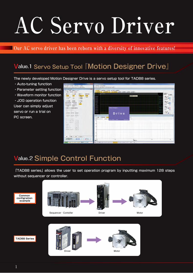
The newly developed Motion Designer Drive is a servo setup tool for TAD88 series.・Auto-tuning function・Parameter setting function・Waveform monitor function・JOG operation functionUser can simply adjust servo or run a trial on PC screen.
AC Servo Driver TAD88Our AC servo driver has been reborn with a diversity of innovative features!
1 2
Value.1 Servo Setup Tool 『Motion Designer Drive』
「TAD88 series」allows the user to set operation program by inputting maximum 128 steps without sequencer or controller.
Value.2 Simple Control Function
User can manipulate while monitoring the condition through Twin Workspace method which consists of Control Workspace (Operation) and View Workspace (Monitor).
Sequencer · Contoller Driver Motor
Incorporates an alarm recorder ‒ an industry first.The AC servo driver is capable of automatically recording all alarms given while the system is in operation, enabling any malfunction to be identified instantaneously.
Alarm generation date/time※
Alarm number Alarm data: position, velocity, electric current, load factor, drive voltage, and circuit board temperature
123
Our AC servo driver is equipped with an alarm recorder ‒ an industry first. The recorder incorporates a calendar and clock functions, enabling the date and time and operational data at the time of alarm occurrence to be stored automatically. This function makes it easy to identify the cause of malfunction in your attempt to recover the unit from the error instantaneously.※Alarm generation date / time are not recorded in TAD8810 series.
Common configration
example
TAD88 Series
Program screen
Gain adjustment
Parameter settings
Alarm historyDriver Motor
NEW SV-NET Series

Damping control which requires high precision is possible. There are various sensors for corresponding motor and they enable high precision control of the motor.
Network: Compatible with SV-NET, RS485, ModbusSensor: Resolver, Incremental encoder, and Serial encoder (17bit, 23bit)
Adjustment for faithful reproduction of sequencer or controller commands has become simple by the auto-tuning feature.
パラメータはカテゴリー別に分類して表示、現在値と変更値も分かりやすく表示
Input operation for motor load and in-position range are easily done by guiding the user in dialogue form.
Smallest class in the industryIn addition to the compact and user-friendly design, it also has luxurious appearance.
●TAD8811 Size 400W:43(W)×145(H)×160(D)mm 750W:63(W)×145(H)×160(D)mm ●TAD8810 Size 30(W)×116(H)×90(D)mm
3 4
Value.4 High Precision Control
Value.5 Compact & Design
AC Servo Driver TAD88Value.3 Auto-tuning Function
Frequency analysis (FFT) display plays an effective role when identifying mechanical resonance point.
Real-time monitor
Tuning record display Frequency analysis (FFT) display
Before auto tuning adjustment
Auto tuning wizard screen
After auto tuning adjustment

Applicable motors : TBL-iⅣSeries, TBL-iⅡSeries and TBL-iⅣs SeriesApplicable sensors : Incremental encoder, serial encoder(17bit to 23bit)and brushless resolver.
5 6
Applicability
Driver model designation
Sensor specifications Table1
AC Servo Driver TAD8811 Series
SV-NET Driver TAD8811 Series SV-NET Driver TAD8811 Series
TAD 8811 N 0 □□□ E □△△Driver series name
Sensors1--- lncremental encoder (INC-SE)3--- Serial encoder (Smart-ABS/INC)7--- Brushless resolver (Smartsyn)
I/F voltage, drive voltage1--- 5V(I/F) AC100V2--- 5V(I/F) AC200V3--- 24V(I/F) AC100V4--- 24V(I/F) AC200V
Note: With respect to driver types, type E900 and onward are of special specifications.Please see specifications peculiar to each product.
Sensor specificationsSee Table 1 (Variable according to sensor type)
Applicable motor typeSee Table 2 (Standard model)
Fixed number No indication on the name plate
Rated driver output current (max. current)1--- 1.1 Arms (3.4 Arms)2--- 2 Arms (5.9 Arms)3--- 4 Arms (11.3 Arms)4--- 6 Arms (15.0 Arms)
Motor and driver applicability Table2
Compliance with various international standards
AC Power Type
Sensor specifications N01□□ N03□□ N07□□E1△△ 2000 C/T Wire-saving 17bit-ABS 1X-BRX 7V-10kHzE2△△ 2048 C/T Wire-saving 17bit-INC (2X-BRX 7V-10kHz)E3△△ 2500 C/T Wire-saving - (4X-BRX 7V-10kHz)E4△△ - - -E5△△ - 23bit-ABS -E6△△ - 23bit-INC -
Note : Those in ( ) refer to products that we will develop and launch in the near future. Brushless resolver is indicated as “BRX”

Applicable motors : TBL-iⅣSeries, TBL-iⅡSeries and TBL-iⅣs SeriesApplicable sensors : Incremental encoder, serial encoder(17bit to 23bit)and brushless resolver.
5 6
Applicability
Driver model designation
Sensor specifications Table1
AC Servo Driver TAD8811 Series
SV-NET Driver TAD8811 Series SV-NET Driver TAD8811 Series
TAD 8811 N 0 □□□ E □△△Driver series name
Sensors1--- lncremental encoder (INC-SE)3--- Serial encoder (Smart-ABS/INC)7--- Brushless resolver (Smartsyn)
I/F voltage, drive voltage1--- 5V(I/F) AC100V2--- 5V(I/F) AC200V3--- 24V(I/F) AC100V4--- 24V(I/F) AC200V
Note: With respect to driver types, type E900 and onward are of special specifications.Please see specifications peculiar to each product.
Sensor specificationsSee Table 1 (Variable according to sensor type)
Applicable motor typeSee Table 2 (Standard model)
Fixed number No indication on the name plate
Rated driver output current (max. current)1--- 1.1 Arms (3.4 Arms)2--- 2 Arms (5.9 Arms)3--- 4 Arms (11.3 Arms)4--- 6 Arms (15.0 Arms)
Motor and driver applicability Table2
Compliance with various international standards
AC Power TypeTBL-iⅡ Series(AC200V, I/F voltage of 24V)
Moter Applicable driverFlange size Rated output Model Model Outline drawing
□40mm
30W TS4601N□□□□E200 TAD8811N0□41E□31 ①50W TS4602N□□□□E200 TAD8811N0□41E□32 ①100W TS4603N□□□□E200 TAD8811N0□41E□33 ①150W TS4604N□□□□E200 TAD8811N0□42E□34 ①
□60mm
100W TS4606N□□□□E200 TAD8811N0□41E□36 ①200W TS4607N□□□□E200 TAD8811N0□42E□37 ①400W TS4609N□□□□E200 TAD8811N0□43E□39 ①600W TS4610N□□□□E200 TAD8811N0□44E□40 ②
□80mm
200W TS4611N□□□□E200 TAD8811N0□42E□41 ①400W TS4612N□□□□E200 TAD8811N0□43E□42 ①600W TS4613N□□□□E200 TAD8811N0□44E□43 ②750W TS4614N□□□□E200 TAD8811N0□44E□44 ②
TBL-iⅡ Series(AC100V, I/F voltage of 24V)Moter Applicable driver
Flange size Rated output Model Model Outline drawing
□40mm
30W TS4601N□□□□E100 TAD8811N0□31E□51 ①50W TS4602N□□□□E100 TAD8811N0□31E□52 ①100W TS4603N□□□□E100 TAD8811N0□32E□53 ①150W TS4604N□□□□E100 TAD8811N0□33E□54 ①
□60mm100W TS4606N□□□□E100 TAD8811N0□32E□56 ①200W TS4607N□□□□E100 TAD8811N0□33E□57 ①400W TS4609N□□□□E100 TAD8811N0□34E□59 ② ※
□80mm 200W TS4611N□□□□E100 TAD8811N0□33E□58 ①
TBL-iⅣ Series(AC200V, I/F voltage of 24V)Moter Applicable driver
Flange size Rated output Model Model Outline drawing
□40mm30W TSM3101N□□□□E200 TAD8811N0□41E□70 ①50W TSM3102N□□□□E200 TAD8811N0□41E□71 ①100W TSM3104N□□□□E200 TAD8811N0□42E□72 ①
□60mm100W TSM3201N□□□□E200 TAD8811N0□42E□73 ①200W TSM3202N□□□□E200 TAD8811N0□43E□74 ①400W TSM3204N□□□□E200 TAD8811N0□43E□75 ① ※
□80mm
200W TSM3301N□□□□E200 TAD8811N0□43E□76 ①400W TSM3302N□□□□E200 TAD8811N0□43E□77 ① ※600W TSM3303N□□□□E200 TAD8811N0□44E□78 ② ※672W TSM3304N□□□□E200 TAD8811N0□44E□79 ② ※
TBL-iⅣ Series(AC100V, I/F voltage of 24V)Moter Applicable driver
Flange size Rated output Model Model Outline drawing
□40mm30W TSM3101N□□□□E100 TAD8811N0□33E□90 ①50W TSM3102N□□□□E100 TAD8811N0□33E□91 ①100W TSM3104N□□□□E100 TAD8811N0□33E□92 ①
□60mm100W TSM3201N□□□□E100 TAD8811N0□33E□93 ①200W TSM3202N□□□□E100 TAD8811N0□34E□94 ②
□80mm 200W TSM3301N□□□□E100 TAD8811N0□34E□96 ②
TBL-iⅣs Series(AC200V, I/F voltage of 24V)Moter Applicable driver
Flange size Rated output Model Model Outline drawing
□40mm50W TSM4102N□□□□E205 TAD8811N0□41E□61 ①100W TSM4104N□□□□E205 TAD8811N0□41E□62 ①
□60mm200W TSM4202N□□□□E205 TAD8811N0□42E□64 ①400W TSM4204N□□□□E205 TAD8811N0□43E□65 ①
□80mm600W TSM4303N□□□□E205 TAD8811N0□44E□68 ② ※750W TSM4304N□□□□E205 TAD8811N0□44E□69 ② ※
Maximum output is limited, when the motor having ※mark is combined with TAD8811.

7 8
SV-NET Driver TAD8811 Series SV-NET Driver TAD8811 Series
Specifications
0 mA15 mA(5V)
1μ s min
2μ s min
1μ s min
(Line driver input : f ≦ 500 kHz)
(Open collector input : f ≦ 200 kHz)
Fig. 1 Position command pulse input waveform
Count
Outline drawing
Outline ①
Outline ②
(Sensor)
(Sensor)
Count
0 mA15 mA(24V)
2.5μ s min
5μ s min
2.5μ s min
Fig. 2 Position command pulse input waveform
(Analog monitor)(Driving power)
(Motor/Regenerative resistor connection)
(Analog monitor)(Driving power)
(Motor/Regenerative resistor connection)
1. General specifications
Basic specifications
Power input AC100V Type (Control/drive power) single-phase AC100~115V±10% 50/60HzAC200V Type (Control/drive power) single-phase/three-phase AC200~230V±10% 50/60Hz
Motor drive system Transistor PWM system (sine wave drive)Structure Base mounting type (back-to-back mounting only)Sensor specifications N01** Incremental encoders (Wire saving)(INC-SE)
N03** Serial encoders (Smart-ABS/INC)N07** Brushless resolver(Smartsyn)1X -BRX 7V-10kHz
Operating environment conditions Temperature: 0~40℃ / humidity: 90%RH or lower (no condensation)I/F voltage DC 5V or DC 24V (command pulse 5V)(depends on type)External connection diagram Refer to P9Applicable standards EU directives
EMCEN55011(group1 classA)EN61000-6-2EN61800-3(category C3)
LVD EN61800-5-1:2007UL standards(※1) UL508C
EU RoHS directive RoHS compliant
Functions
Communication software specification SV-NETControl mode ①Position control ②Velocity control ③Current control (Choose parameter)Pulse command input Pulse mode ①CCW/CW pulse ②Pulse/direction (Choose parameter)
Positioning accuracy Within ± 1pulse (Command standard)Analog command input (±10V)
Velocity command inputCurrent command input
Command scale and polarity depend on parameters.6000rpm/10V or 5Arms/10V (factory setting)
Command resolution ±11bitAuto tuning Executed via conversion of associated mode.Electronic gear Control the position by multiplying the command pulse by (N/M).
N: Command pulse inputted to rotate the motor shaft M times. (1~230) M: Rotational speed of motor shaft per number of command pulse(N). (1~214)
Gain switching function Switching of control gain is possible via positional error and velocity command value; switching via signal input also possible.
External encoder input Full-closed position control is possible by feeding back the load axis encoder.Recommended load inertia Within 30 times the motor inertia.Rotation direction CCW rotation as viewed from the axial direction is considered normal direction. (Factory setting)Parameters Parameter setting is possible on the front setting board or by connecting (USB, SV-NET) to PC.
・Control mode ・Analog command scale ・Position loop gain・Analog command offset ・Velocity loop gain ・Zero clamp voltage・Velocity loop integral time ・Acceleration limit ・Feedforward quantity time・Setting for encoder frequency-divided output ・Resonator filter ・Electronic gear ratio・Velocity limit ・Overspeed alarm level ・Current limit・Overload alarm level ・In-position range Among others
Regenerative functions Built-in regenerative circuit, external resistor (optional)Dynamic brake Built-in dynamic brake; operating conditions subject to parameter settingProtection Hardware errors Overspeed, power device abnormality (overcurrent), sensor abnormality, driving power abnormality, EEPROM abnormality, CPU abnormality, etc.
Software errors Overload, excessive error, etc.Alarm history Capable of memorizing up to 8 alarms.Display, setting Four 5-digit LED buttons for display and setting
Displays control mode, alarm and state of control signal input.※1.Products other than standard model in this catalog are not UL tested.
2. Input/output signalsI/O Name Description (Factory Setting)
Input signals
IN1(SV-ON) Servo is ON at “L” and OFF at “H”.Functions of this 8ch universal input unit can be modified by changing parameters
“L”: Photo-coupler is energized.“H”: Photo-coupler is not energized.
IN2(F-LMT)IN3(R-LMT)
CCW operation is disabled at “H”.Logic alteration is possible.CW operation is disabled at “H”. Logic alteration is possible.
IN4(ALM-RST) Alarm is reset at “L”.IN5(C-RST) Error counter is reset at “L”.IN6(EX_ALM) External alarm at “L”.IN7(HOME) Original signal is ON at “L”.IN8(PLS-INH) Pules input is ignored at “L”.F-PLSR-PLS
CCW pulse/pulse inputCW pulse/direction (via parameter)
f ≦ 500kHz:Fig.1f ≦ 200kHz:Fig.2
ANALOG-IN Analog command in put (± 10V)EX-LEADEX-LAG
LEAD/LAG signal input for load axis encoder. Signal for advance when motor is in CCW rotation is to be connected to LEAD while that for lag is to be connected to LAG. f ≦ 125kHz
Output signals
OUT1(ALM) “H” during alarm and “L” during normal operation.Functions of this 5ch universal output unit can be modified by changing parameters.
“L”: Photo-coupler is ON.“H”: Photo-coupler is OFF.
(50mA max)
OUT2(INP) “L” when position error is below set value.OUT3(RDY) “L” when servo is ready.OUT4(BRK-SG) “L” when brake is released.OUT5(STOP-SG)“L” when motor stops.LEADLAG
Outputs frequency-divided sensor signals.(For details, refer to instruction manual.) Line-driver output
Z Outputs Z signals.(For details, refer to instruction manual.)MONITOR-1MONITOR-2
Monitors ① current command, ② velocity feedback, etc.MONITOR-2 Parameter-based setting for matters to be monitored and scale of monitoring.

※1 Connectable to either single-phase or three-phase power source※2 Power supply voltage and I/F voltage vary according to N number type.※3 We recommend sensor SHIELD be connected to DG. Note, however, that there are some cases where noise tolerance may increase by connecting to CN2-CASE ( ).
9 10
External connections
Analog monitor
SHIELD
UPPER SIGNAL GND
transceiver
Regenerative resistor
Power input
SV-NET DRIVER
TAD8811N0***
R2
R1
R3
HCPL-M456 equivalent
LTV-354 equivalent
LTV-352T equivalent
AM26C31 equivalent
(Note) R2: 1.6kΩ(24V- Open collector input)(Note) R3: 240Ω(Line driver input)
(Note) R1: 5V interface is 330Ω24V interface is 3.3KΩ
Input circuit
Output circuit
Sensors1--- Incremental encoder (INC-SE)3--- Serial encoder (Smart-ABS/INC)7--- Brushless resolver (Smartsyn)
I/F voltage, drive voltage1--- 5V(I/F) AC100V2--- 5V(I/F) AC200V3--- 24V(I/F) AC100V4--- 24V(I/F) AC200V
Rated driver output current (max. current)1--- 1.1 Arms (3.4 Arms)2--- 2 Arms (5.9 Arms)3--- 4 Arms (11.3 Arms)4--- 6 Arms (15.0 Arms)
SV-NET Driver TAD8811 Series SV-NET Driver TAD8811 Series
ENCODER(Smart-ABS)(Smart-INC)
(Smart-ABSのみ)Backup battery
SV-NET DRIVER
SV-NET DRIVERSV-NET DRIVER
TBL-i SERVO-MOTOR
Shield
Brushless resolver
TBL-i SERVO-MOTOR
Shield
Serial encoder TBL-i SERVO-MOTORIncremental encoder
Shield
Options
Connectors used
(1)For input/output signals CN1 :10250-52A2PL (Sumitomo 3M) or equivalent (2)For sensor connection CN2 :10220-52A2PL (Sumitomo 3M) or equivalent (3)For SV-NET/485 CN5/CN6 :1-1827876-3 (TE CONECTIVITY) or equivalent (4)For analog monitor CN8 :2417RJ-04-PHD (Neltron) or equivalent
Accessories
(1)Connector for power supply connection TB1 :0134-32-6588-03 (DINKLE) or equivalent (2)Connector for motor connection TB2 :0134-1105 (DINKLE) or equivalent
The following options are available.
Model markingReceptacle housing :1-1318118-6(TE Connectivity)Receptacle contact :1318108-1(TE Connectivity)
Plug :10120-3000PE(3M)Shell :10320-52A0-008(3M)
Crosslinked PVC cable
Heat-shrink tubeSensor-sideDriver-side
Heat-shrink tube
(φ
6.3)
L+5%-0(20)
●Sensor cable(CN2):For TBL-iⅡ, -iⅣ Motor・Incremental encoder・Serial encoder(Smart-INC)・Brushless resolver
●Sensor cable(CN2):For TBL-iⅣs Motor・Serial encoder(Smart-INC)
(φ
5.3)
Crosslinked PVC cableModel marking
Heat-shrink tube
Driver-sidePlug :10120-3000PE(3M)Shell :10320-52A0-008(3M)
L+5% 0Sensor-side
Connector :JN6FR07SM1(JAE)Contact :LY10-C1-A1-10000(JAE)
ModelEUA1281N0010
N0030N0050N0100
1m3m5m
10m
Length
ModelEUA1283N0010
N0030N0050N0100
1m3m5m
10m
Length
ModelEUA9204N0010
N0030N0050N0100
1m3m5m
10m
Length
ModelEUA9203N0010
N0030N0050N0100
1m3m5m
10m
Length
Battery unit
Receptacle housing : 1-1318118-6(TE Connectivity)Receptacle contact : 1318108-1(TE Connectivity)
Plug :10120-3000PE(3M)Shell :10320-52A0-008(3M)
Crosslinked PVC cable Heat-shrink tube
Sensor-sideDriver-side
Heat-shrink tube Model marking
L+5%-0(20)
(φ
6.3)
(φ
8)
(90)
●Sensor cable(CN2):For TBL-iⅡ, -iⅣ Motor・Serial encoder(Smart-ABS)
●Sensor cable(CN2):For TBL-iⅣs Motor・Serial encoder(Smart-ABS)
(φ
5.3)
Crosslinked PVC cableModel marking Battery unit Heat-shrink tube
Driver-sidePlug :10120-3000PE(3M)Shell :10320-52A0-008(3M)
(90)
L+5% 0
Sensor-sideConnector :JN6FR07SM1(JAE)Contact :LY10-C1-A1-10000(JAE)
Fixed number No indication on the name plate

RBV1.25-3(JST)or equivalent
Connector :10150-3000PE(3M)Shell :10350-52F0-008(3M)
F0.3-3(DST)or equivalent
1
2
50
Shielded CableHeat-shrink tube
(120)
(80)
L+ 5%- 0%
-0
Receptacle housing :1-1827864-3(TE Connectivity)Receptacle contact :1871744-1(TE Connectivity)
Model marking
Device net cable
734-105(WAGO)
12345
L+5% (50)(50)
B3B2B1
A3A2A1
ModelEUA1424N0003
N0010N0030N0050
0.3m1 m3 m5 m
Length
ModelEUA1425N0003
N0010N0030N0050
0.3m1 m3 m5 m
Length
ModelEUA1354N0010
N0030N0050N0100
1m3m5m
10m
Length
ModelEUA1287N0010
N0030N0050N0100
1m3m5m
10m
Length
ModelEUA1289N0010
N0020N0030
1m2m3m
Length
ModelEUA1459N0010
N0015N0020N0030
0.8m1.3m1.8m2.8m
Length
Device net cable
Model marking
Receptacle housing :1-1827864-3(TE Connectivity)Receptacle contact :1871744-1(TE Connectivity)
-0
Receptacle housing:1-1827864-3(TE Connectivity)Receptacle contact :1871744-1(TE Connectivity)
(50) (50)L+5%
B3B2B1
A3A2A1
B1B2B3
A1A2A3
●SV-NET cable(CN5,6)・For the connection between the drivers
Housing :2418HJ-04-PHD(Neltron)Terminal :2418TJ-PHD(Neltron)
1
3
2
4
L+10%- 0
●Analog monitor cable(CN8)
●I/O cable(CN1)・Pulse command, Line driver
RBV1.25-3(JST)or equivalent
Connector :10150-3000PE(3M)Shell :10350-52F0-008(3M)
F0.3-3(DST)or equivalent
1
2
50
Shielded CableHeat-shrink tube
(120)
(80)
L+ 5%- 0%
●I/O cable(CN1)・Pulse command, Open collector
●SV-NET cable(CN5,6)・For the controller and the driver of the connection
Ferr i te core :E04SR211132 (SEIWA)
Shielded Cable
Ferr i te core :E04SR211132 (SEIWA)
4
1 4
32
1
39
11.5
39
810
.77.
2
12
12
15.3
4.5
7.5
12 L±80
φ5
(50)(50)
●USB cable(CN7)
●Backup battery(For Smart-ABS) :EUA1284●Battery unit(For Smart-ABS) :AUA3972(With Backup battery)●SV-NET terminal Connector(CN5,6) :EUA1294●Regenerative resistor(TB2) :EUA1290(80W-47Ω)●Connector set :EU6657(CN1,CN2)
M4 crimp terminal
No connector
FG(Green/Yellow)
W(Black)V(White)U(Red)
Heat-shrink tube
Driver-side
Motor-side
Heat-shrink tube6-core Shielded Cable
Receptacle housing :178289-3(TE Connectivity)Receptacle contact :175218-2(TE Connectivity)
Model marking
(10)(50)L+5%-0(20)
(φ
7.2)
●Motor cable(TB2):For TBL-iⅡ, -iⅣ Motor・No brake
ModelEUA9205N0010
N0030N0050N0100
1m3m5m
10m
Length
ModelEUA1280N0010
N0030N0050N0100
1m3m5m
10m
Length
ModelEUA1292N0010
N0030N0050N0100
1m3m5m
10m
Length
FG(Green/Yellow)W(Black)V(White)U(Red)
BK(Yellow)BK(Blue)
L+5% 0 (
φ7.
2)
(50) (10)(20)
Model marking
Receptacle housing :178289-3(TE Connectivity)Receptacle contact :175218-2(TE Connectivity) U,V,W,FG :175217-2(TE Connectivity) BK
6-core Shielded Cable
Heat-shrink tube
Motor-side
Driver-sideHeat-shrink tube No connectorM4 crimp terminal
●Motor cable(TB2):For TBL-iⅡ, -iⅣ Motor・With brake
●Sensor cable(CN2):For TBL-iⅣs Motor・Brushless resolver
(φ
5.3)
Crosslinked PVC cableModel marking
Heat-shrink tubeDriver-side
Plug :10120-3000PE(3M)Shell :10320-52A0-008(3M)
L+5% 0Sensor-side
Connector :JN6FR07SM1(JAE)Contact :LY10-C1-A1-10000(JAE)
ModelEUA9201N0010
N0030N0050N0100
1m3m5m
10m
Length
ModelEUA9202N0010
N0030N0050N0100
1m3m5m
10m
Length
●Motor cable(TB2):For TBL-iⅣs Motor
●Brake cable:For TBL-iⅣs Motor
(φ
5.1)
2-core robot cable
Model marking Heat-shrink tube Driver-sideNo connector
L+5% 0
Motor-sideConnector :JN6FR02SM1(JAE)Contact :LY10-C1-A1-10000(JAE)
BK(Yellow)
BK(Yellow)
(10)(50)
(φ
6.2)
4-core robot cable
Model marking Heat-shrink tube
Driver-sideNo connector
L+5% 0
Motor-sideConnector :JN6FS04SJ2(JAE)Contact :ST-JN5ーS-C1B-100(A534G)(JAE)
V(White)
U(Red)
W(Black)
FG(Green/Yellow)
(10)(50)
V1.25-M4
11 12
SV-NET Driver TAD8811 Series SV-NET Driver TAD8811 Series

RBV1.25-3(JST)or equivalent
Connector :10150-3000PE(3M)Shell :10350-52F0-008(3M)
F0.3-3(DST)or equivalent
1
2
50
Shielded CableHeat-shrink tube
(120)
(80)
L+ 5%- 0%
-0
Receptacle housing :1-1827864-3(TE Connectivity)Receptacle contact :1871744-1(TE Connectivity)
Model marking
Device net cable
734-105(WAGO)
12345
L+5% (50)(50)
B3B2B1
A3A2A1
ModelEUA1424N0003
N0010N0030N0050
0.3m1 m3 m5 m
Length
ModelEUA1425N0003
N0010N0030N0050
0.3m1 m3 m5 m
Length
ModelEUA1354N0010
N0030N0050N0100
1m3m5m
10m
Length
ModelEUA1287N0010
N0030N0050N0100
1m3m5m
10m
Length
ModelEUA1289N0010
N0020N0030
1m2m3m
Length
ModelEUA1459N0010
N0015N0020N0030
0.8m1.3m1.8m2.8m
Length
Device net cable
Model marking
Receptacle housing :1-1827864-3(TE Connectivity)Receptacle contact :1871744-1(TE Connectivity)
-0
Receptacle housing:1-1827864-3(TE Connectivity)Receptacle contact :1871744-1(TE Connectivity)
(50) (50)L+5%
B3B2B1
A3A2A1
B1B2B3
A1A2A3
●SV-NET cable(CN5,6)・For the connection between the drivers
Housing :2418HJ-04-PHD(Neltron)Terminal :2418TJ-PHD(Neltron)
1
3
2
4
L+10%- 0
●Analog monitor cable(CN8)
●I/O cable(CN1)・Pulse command, Line driver
RBV1.25-3(JST)or equivalent
Connector :10150-3000PE(3M)Shell :10350-52F0-008(3M)
F0.3-3(DST)or equivalent
1
2
50
Shielded CableHeat-shrink tube
(120)
(80)
L+ 5%- 0%
●I/O cable(CN1)・Pulse command, Open collector
●SV-NET cable(CN5,6)・For the controller and the driver of the connection
Ferr i te core :E04SR211132 (SEIWA)
Shielded Cable
Ferr i te core :E04SR211132 (SEIWA)
4
1 4
32
1
39
11.5
39
810
.77.
2
12
12
15.3
4.5
7.5
12 L±80
φ5
(50)(50)
●USB cable(CN7)
●Backup battery(For Smart-ABS) :EUA1284●Battery unit(For Smart-ABS) :AUA3972(With Backup battery)●SV-NET terminal Connector(CN5,6) :EUA1294●Regenerative resistor(TB2) :EUA1290(80W-47Ω)●Connector set :EU6657(CN1,CN2)
M4 crimp terminal
No connector
FG(Green/Yellow)
W(Black)V(White)U(Red)
Heat-shrink tube
Driver-side
Motor-side
Heat-shrink tube6-core Shielded Cable
Receptacle housing :178289-3(TE Connectivity)Receptacle contact :175218-2(TE Connectivity)
Model marking
(10)(50)L+5%-0(20)
(φ
7.2)
●Motor cable(TB2):For TBL-iⅡ, -iⅣ Motor・No brake
ModelEUA9205N0010
N0030N0050N0100
1m3m5m
10m
Length
ModelEUA1280N0010
N0030N0050N0100
1m3m5m
10m
Length
ModelEUA1292N0010
N0030N0050N0100
1m3m5m
10m
Length
FG(Green/Yellow)W(Black)V(White)U(Red)
BK(Yellow)BK(Blue)
L+5% 0 (
φ7.
2)
(50) (10)(20)
Model marking
Receptacle housing :178289-3(TE Connectivity)Receptacle contact :175218-2(TE Connectivity) U,V,W,FG :175217-2(TE Connectivity) BK
6-core Shielded Cable
Heat-shrink tube
Motor-side
Driver-sideHeat-shrink tube No connectorM4 crimp terminal
●Motor cable(TB2):For TBL-iⅡ, -iⅣ Motor・With brake
●Sensor cable(CN2):For TBL-iⅣs Motor・Brushless resolver
(φ
5.3)
Crosslinked PVC cableModel marking
Heat-shrink tubeDriver-side
Plug :10120-3000PE(3M)Shell :10320-52A0-008(3M)
L+5% 0Sensor-side
Connector :JN6FR07SM1(JAE)Contact :LY10-C1-A1-10000(JAE)
ModelEUA9201N0010
N0030N0050N0100
1m3m5m
10m
Length
ModelEUA9202N0010
N0030N0050N0100
1m3m5m
10m
Length
●Motor cable(TB2):For TBL-iⅣs Motor
●Brake cable:For TBL-iⅣs Motor
(φ
5.1)
2-core robot cable
Model marking Heat-shrink tube Driver-sideNo connector
L+5% 0
Motor-sideConnector :JN6FR02SM1(JAE)Contact :LY10-C1-A1-10000(JAE)
BK(Yellow)
BK(Yellow)
(10)(50)
(φ
6.2)
4-core robot cable
Model marking Heat-shrink tube
Driver-sideNo connector
L+5% 0
Motor-sideConnector :JN6FS04SJ2(JAE)Contact :ST-JN5ーS-C1B-100(A534G)(JAE)
V(White)
U(Red)
W(Black)
FG(Green/Yellow)
(10)(50)
V1.25-M4
11 12
SV-NET Driver TAD8811 Series SV-NET Driver TAD8811 Series

13 14
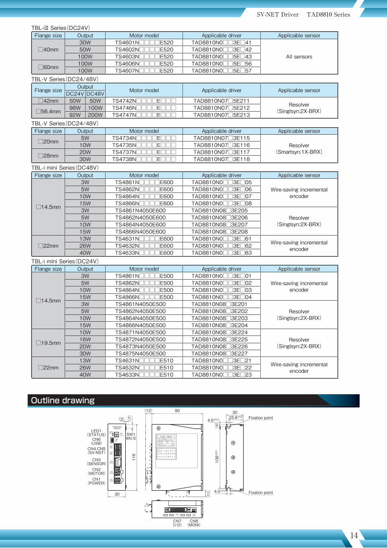
Applicable motors : TBL-iIV Series(Small Size), TBL-iII Series(Small Size), TBL-V Series and TBL-i mini SeriesApplicable sensors : Incremental encoder, serial encoder(17 to 23 bit) and brushless resolver
Applicability
Driver model designation
Sensor specifications Table1
AC Servo Driver TAD 8810 Series
TAD 8810 N 0 □□□ E □△△Driver series name
Sensors 1--- Wire-saving incremental encoder (INC-SE) 3--- Serial encoder (17 bit or 23 bit ABS/INC) 7--- Brushless resolver (Smartsyn) 8--- Brushless resolver (Singlsyn for 14.5 and 19.5 mm square motor)
Fixed number No indication on the name plate
Sensor specifications See Table 1 (Variable according to sensor type)
Motor type See Table 2
Rated driver output current (max. current) 3---4 Arms(12Arms) 5---8 Arms(24Arms)
Motor and driver applicability Table2
Options 0--- Standard
Outline drawing
TAMAGAWATAD8810
STATUS
CN6
SW1LED1MAC-ID SW1
MAC-ID
(2)
USB
CN5COM2
CN4COM1
CN3SENSOR
CN2MOTOR
CN1POWER
CN7I/O
CN8MONI
CN6(USB)
LED1(STATUS)
CN4,CN5(SV-NST)
CN3(SENSOR)
CN2(MOTOR)
CN1(POWER)
CN7(I/O)
CN8(MONI)
30
116
108±
0.5
(7)
(12) 90
(11
)
SV-NET DRIVERTYPE TAD8810N****E***
S/N ******INPUT(CONT.)
INPUT(DRV.)
OUTPUT *** W
DC24 V
DC** V
DATE ******.***.* A
*.* A
RoHSTAMAGAWA SEIKI CO., LTD. MADE IN JAPAN
A B C D E FG H K L M N O P QR S T U V W X Y Z
v e r .
(4)
4.5±0.2 25.8±0.5
4.5±0.2
30Fixation point
Fixation point
DC Power Type
SV-NET Driver TAD8810 Series SV-NET Driver TAD8810 Series
Sensor specificationsN01□□ N03□□ N07□□ N08□□
E1△△ 2000 C/T 17bit-ABS 1X-BRX -E2△△ 2048 C/T 17bit-INC 2X-BRX 2X-BRXE3△△ 2500 C/T - (4X-BRX) -E4△△ - - - -E5△△ - 23bit-ABS - -E6△△ - 23bit-INC - -
TBL-iⅣ Series(DC48V)Flange size Output Motor model Applicable driver Applicable sensor
□40mm30W TSM3101N□□□□E040 TAD8810N0□03E□84
All sensors
50W TSM3102N□□□□E040 TAD8810N0□03E□85100W TSM3104N□□□□E040 TAD8810N0□05E□86
□60mm 100W TSM3201N□□□□E040 TAD8810N0□05E□87200W TSM3202N□□□□E040 TAD8810N0□05E□88
□80mm 200W TSM3301N□□□□E040※ TAD8810N0□05E□89TBL-iⅣ Series(DC24V)Flange size Output Motor model Applicable driver Applicable sensor
□40mm30W TSM3101N□□□□E020 TAD8810N0□03E□44
All sensors50W TSM3102N□□□□E020 TAD8810N0□05E□45100W TSM3104N□□□□E020 TAD8810N0□05E□46
□60mm 100W TSM3201N□□□□E020※ TAD8810N0□05E□47TBL-iⅡ Series(DC48V)Flange size Output Motor model Applicable driver Applicable sensor
□40mm30W TS4601N□□□□E620 TAD8810N0□□3E□81
All sensors50W TS4602N□□□□E620 TAD8810N0□□3E□82100W TS4603N□□□□E620 TAD8810N0□□3E□83
□60mm 100W TS4606N□□□□E620 TAD8810N0□□3E□96200W TS4607N□□□□E620 TAD8810N0□□5E□97
Maximum output is limited when the motor having ※ mark is combined with TAD8810.
・ Those in ( ) refer to products that we will develop and launch in the near future.
・17 bit absolute encoder is indicated as“17bit-ABS”・17 bit incremental encoder is indicated as “17bit-INC”・Brushless resolver is indicated as “BRX”
13 14
Applicable motors : TBL-iIV Series(Small Size), TBL-iII Series(Small Size), TBL-V Series and TBL-i mini SeriesApplicable sensors : Incremental encoder, serial encoder(17 to 23 bit) and brushless resolver
Applicability
Driver model designation
Sensor specifications Table1
AC Servo Driver TAD 8810 Series
TAD 8810 N 0 □□□ E □△△Driver series name
Sensors 1--- Wire-saving incremental encoder (INC-SE) 3--- Serial encoder (17 bit or 23 bit ABS/INC) 7--- Brushless resolver (Smartsyn) 8--- Brushless resolver (Singlsyn for 14.5 and 19.5 mm square motor)
Fixed number No indication on the name plate
Sensor specifications See Table 1 (Variable according to sensor type)
Motor type See Table 2
Rated driver output current (max. current) 3---4 Arms(12Arms) 5---8 Arms(24Arms)
Motor and driver applicability Table2
Options 0--- Standard
Outline drawing
TAMAGAWATAD8810
STATUS
CN6
SW1LED1MAC-ID SW1
MAC-ID
(2)
USB
CN5COM2
CN4COM1
CN3SENSOR
CN2MOTOR
CN1POWER
CN7I/O
CN8MONI
CN6(USB)
LED1(STATUS)
CN4,CN5(SV-NST)
CN3(SENSOR)
CN2(MOTOR)
CN1(POWER)
CN7(I/O)
CN8(MONI)
30
116
108±
0.5
(7)
(12) 90
(11
)
SV-NET DRIVERTYPE TAD8810N****E***
S/N ******INPUT(CONT.)
INPUT(DRV.)
OUTPUT *** W
DC24 V
DC** V
DATE ******.***.* A
*.* A
RoHSTAMAGAWA SEIKI CO., LTD. MADE IN JAPAN
A B C D E FG H K L M N O P QR S T U V W X Y Z
v e r .
(4)
4.5±0.2 25.8±0.5
4.5±0.2
30Fixation point
Fixation point
DC Power Type
SV-NET Driver TAD8810 Series SV-NET Driver TAD8810 Series
TBL-iⅡ Series(DC24V)Flange size Output Motor model Applicable driver Applicable sensor
□40mm30W TS4601N□□□□E520 TAD8810N0□□3E□41
All sensors50W TS4602N□□□□E520 TAD8810N0□□3E□42100W TS4603N□□□□E520 TAD8810N0□□5E□43
□60mm 100W TS4606N□□□□E520 TAD8810N0□□5E□56100W TS4607N□□□□E520 TAD8810N0□□5E□57
TBL-V Series(DC24/48V)
Flange size Output Motor model Applicable driver Applicable sensorDC24V DC48V□42mm 50W 50W TS4742N□□□□E□□□ TAD8810N07□5E211 Resolver
(Singlsyn:2X-BRX)□56.4mm 98W 100W TS4746N□□□□E□□□ TAD8810N07□5E21292W 200W TS4747N□□□□E□□□ TAD8810N07□5E213
TBL-V Series(DC24/48V)Flange size Output Motor model Applicable driver Applicable sensor
□20mm 5W TS4734N□□□□E□□□ TAD8810N07□3E115Resolver
(Smartsyn:1X-BRX)10W TS4735N□□□□E□□□ TAD8810N07□3E116
□28mm 20W TS4737N□□□□E□□□ TAD8810N07□3E11730W TS4738N□□□□E□□□ TAD8810N07□3E118
TBL-i mini Series(DC48V)Flange size Output Motor model Applicable driver Applicable sensor
□14.5mm
3W TS4861N□□□□E600 TAD8810N0□□3E□05Wire-saving incremental
encoder5W TS4862N□□□□E600 TAD8810N0□□3E□0610W TS4864N□□□□E600 TAD8810N0□□3E□0715W TS4866N□□□□E600 TAD8810N0□□3E□083W TS4861N4050E600 □ TAD8810N08□3E205□
Resolver(Singlsyn:2X-BRX)
5W TS4862N4050E600 □ TAD8810N08□3E206□10W TS4864N4050E600 □ TAD8810N08□3E207□15W TS4866N4050E600 □ TAD8810N08□3E208□
□22mm13W TS4631N□□□□E600 TAD8810N0□□3E□61 Wire-saving incremental
encoder26W TS4632N□□□□E600 TAD8810N0□□3E□6240W TS4633N□□□□E600 TAD8810N0□□3E□63
TBL-i mini Series(DC24V)Flange size Output Motor model Applicable driver Applicable sensor
□14.5mm
3W TS4861N□□□□E500 TAD8810N0□□3E□01Wire-saving incremental
encoder5W TS4862N□□□□E500 TAD8810N0□□3E□0210W TS4864N□□□□E500 TAD8810N0□□3E□0315W TS4866N□□□□E500 TAD8810N0□□3E□043W TS4861N4050E500 □ TAD8810N08□3E201□
Resolver(Singlsyn:2X-BRX)
5W TS4862N4050E500 □ TAD8810N08□3E202□10W TS4864N4050E500 □ TAD8810N08□3E203□15W TS4866N4050E500 □ TAD8810N08□3E204□
□19.5mm
10W TS4871N4050E500 □ TAD8810N08□3E224□Resolver
(Singlsyn:2X-BRX)16W TS4872N4050E500 □ TAD8810N08□3E225□20W TS4873N4050E500 □ TAD8810N08□3E226□30W TS4875N4050E500 □ TAD8810N08□3E227□
□22mm13W TS4631N□□□□E510 TAD8810N0□□3E□21 Wire-saving incremental
encoder26W TS4632N□□□□E510 TAD8810N0□□3E□2240W TS4633N□□□□E510 TAD8810N0□□3E□23

15 16
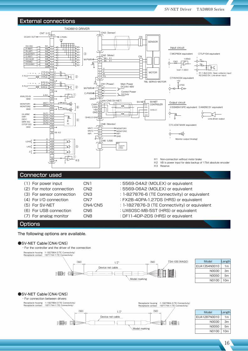
External connectionsSpecifications
SV-NET Driver TAD8810 Series SV-NET Driver TAD8810 Series
(SV-ON)
DC24V OUT
(F-RMT)(R-LMT)(ALM-RST)(C-RST)(EX-ALM)(HOME)(PLS-INH)
IN1IN2IN3IN4IN5IN6IN7IN8GND
CN7 (I/O) CN3 (Sensor)
CN2 (Motor)
CN
CN
F-PLS
F-PLS1+F-PLS+F-PLS-
F-PLS
R-PLS1+R-PLS+R-PLS-
A-IN1
MNT1
ANALOG-INGND
GND
GND
MONITOR1MNT2MONITOR2
OUT1(ALARM)OUT2(INP)OUT3(RDY)OUT4(BRK-SG)OUT5
VB ※2
AA
ZZ
BB
(STOP-SG)
LEAD
LAG
Z
1
2345678910
11
56
21
34
1234
A1B1A2B2
1234
A3B3
12131415161718
1920
212223
242526272829
30
333435363738
3940
TAD8810 DRIVER
C-PWR++5V
③
M-PWR+
FG CN1(Power)
CN4/CN5(SV-NET)
CN8 (Monitor)
CN6 (USB)
SV-NET
Main PowerDC24V/48V
Control PowerDC24V
②++-
R1R2
②
①
⑥
④
⑤
++-
R1R2
R1
R2
-+
①-+
-+
MNT1
MNT2
X5
SV-NETCONTROLER
TBL SERVOーMOTOR
M-PWR+
C-PWR+
GND
BK+BK-
UVWFG
※1※1
+-+-
CAN+CAN-+5VGND
(SHIELD)GND
MNT1 MONITOR1MONITOR2MNT2
INP/ INP/GND
GND
GNDCAN-
CAN++24V
(SHIELD)
PCParametercontrol& TEST
※1 Non-connection without motor brake※2 VB is power input for data backup of 17bit absolute encoder※3 Reserve
Input circuit
Output circuit
12kΩ
470Ω
1.65kΩ
②TLP104 equivalent①MCP604 equivalent
③74VHC04 equivalent
④SSM5N15FE equivalent ⑤AM26C31 equivalent
⑥TLV2474AIW equivalent
Vref+(1.65V)
+5V
R1:1.6kΩ(24V, Open collector input)R2:240Ω(5V, Line-driver input)
Line-driver output
Monitor output(Analog)
Options
Connector used (1)For power input CN1 :5569-04A2(MOLEX)or equivalent (2)For motor connection CN2 :5569-06A2(MOLEX)or equivalent (3)For sensor connection CN3 :1-827876-6(TE Connectivity)or equivalent (4)For I/O connection CN7 :FX2B-40PA-1.27DS(HRS)or equivalent (5)For SV-NET CN4/CN5 :1-1827876-3(TE Connectivity)or equivalent (6)For USB connection CN6 :UX60SC-MB-5ST(HRS)or equivalent (7)For analog monitor CN8 :DF11-4DP-2DS(HRS)or equivalent
※3
The following options are available.
●SV-NET Cable(CN4/CN5)・For connection between drivers
●SV-NET Cable(CN4/CN5)・For the controller and the driver of the connection
-0
Receptacle housing :1-1827864-3(TE Connectivity)Receptacle contact :1871744-1(TE Connectivity)
Model marking
Device net cable
734-105(WAGO)
12345
L+5% (50)(50)
B3B2B1
A3A2A1
ModelEUA1354N0010
N0030N0050N0100
1m3m5m
10m
Length
ModelEUA1287N0010
N0030N0050N0100
1m3m5m
10m
LengthDevice net cable
Model marking
Receptacle housing :1-1827864-3(TE Connectivity)Receptacle contact :1871744-1(TE Connectivity)
-0
Receptacle housing :1-1827864-3(TE Connectivity)Receptacle contact :1871744-1(TE Connectivity)
(50) (50)L+5%
B3B2B1
A3A2A1
B1B2B3
A1A2A3
SENSOR
MOTOR
1. General specifications
Basic specifications
Power input Driving power DC24V±10% / DC48V±10%Control power DC24V±10%
Motor driving system Transistor PWM system(sine wave drive)Structure Base mounting type(back-to-back mounting only)Sensor specifications N1** Incremental encoder(Wire-saving)
N3** Serial encoder(Smart-ABS/INC)N7** Brushless resolver(Smartsyn) 1X, 2X -BRX
Operating environment conditions Temperature: 0~40℃ / Humidity: 90%RH or lower(no condensation)External connection diagram CND000414W00CE mark Declaration planningRoHS directive RoHS compliant
Functions
Communication software specification SV-NETControl mode ①Position control ②Speed control ③Current control(Parameter selection)Pulse command input Pulse mode ①CCW/CW pulse ②PULSE/Direction(Parameter selection)
Positioning accuracy Within ±1 pulse(Command standard)Analog command input(±10V)
Velocity command inputCurrent command input
Command scale and polarity depend on parameters.6000rpm/10V or maximum current of motor/10V(Factory setting)
Command resolution ±11bitAuto tuning Executed by switching of mode
Electronic gearControl the position by multiplying the command pulse by “N” or M”N: Number of command pulse inputted to rotate the motor shaft M times(1 to 230)M: Rotation number of motor shaft per number of command pulse “N”(1 to 214)
Gain switching function Switching of control gain is possible via positional error and velocity command value; switching via signal input also possible.
Recommended load inertia Within 30 times of motor inertiaRotation direction CCW as viewed from the motor axis is considered forward rotation.Parameters Parameter setting is possible by connecting to PC(USB, SV-NET)
・Control mode ・Analog command scale・Position loop gain ・Analog command offset・Velocity loop gain ・Zero clamp voltage・Velocity loop integral time ・Acceleration limit・Feedforward quantity ・Setting for encoder frequency-divided output・Resonator filter ・Electronic gear ratio・Velocity limit ・Over-speed alarm level・Current limit ・Over-load alarm level・In-position range Among others
Protection Hardware error Over-speed, power device abnormality (over-current), sensor abnormality,driving power abnormality, EEPROM abnormality, CPU abnormality, etc.
Software error Over-load, excessive error, etc.Alarm history Capable of memorizing up to 8 alarms
Display 2-color LEDControl mode, alarm, warning indication
2. Input/output signalsI/O Name Description(Factory setting)
Input signals
IN1(SV-ON) Servo is ON at “1” and OFF at “0”.8ch universal inputFunctions of this can be modified by changing parameters.
I/F voltage: DC 5V to 24V
“1” L level"“0” H level or open
IN2(F-LMT)IN3(R-LMT)
CCW operation is disabled at “0”. Logic alteration is possible.CW operation is disabled at “0”. Logic alteration is possible.
IN4(ALM-RST) Alarm is reset at “1”.IN5(C-RST) Error counter is reset at “1”.IN6(EX_ALM) External alarm at “1”IN7(HOME) Origin signal is ON at “1”.IN8(PLS-INH) Pulse input is ignored at “1”.F-PLSR-PLS
CCW pulse/PULSE inputCW pulse/Direction(via parameter)
f ≦ 500kHz:Fig.1f ≦ 200kHz:Fig.2
ANALOG-IN1 Analog command input(± 10V)ANALOG-IN2 Analog command input(± 10V) Reserve
Output signals
OUT1(ALM) “0” during alarm and “1” during normal operation 5ch universal inputFunctions of this can be modified by changing parameters.
Open-drain output
OUT2(INP) “1” when position error is set value or below.OUT3(RDY) “1” when servo is ready.OUT4(BRK-SG) “1” when motor stops.
OUT5(STOP-SG) “1” when brake is released.
LEADLAG
Outputs frequency-divided sensor signals.(Refer to instruction manual for details) Line-driver output
Z Outputs Z signal.(Refer to instruction manual for details)
MONITOR-1MONITOR-2
Monitors ① current command, ② velocity feedback, etc.Parameter-based setting for monitoring content and scale
15 16
External connectionsSpecifications
SV-NET Driver TAD8810 Series SV-NET Driver TAD8810 Series
(SV-ON)
DC24V OUT
(F-RMT)(R-LMT)(ALM-RST)(C-RST)(EX-ALM)(HOME)(PLS-INH)
IN1IN2IN3IN4IN5IN6IN7IN8GND
CN7 (I/O) CN3 (Sensor)
CN2 (Motor)
CN
CN
F-PLS
F-PLS1+F-PLS+F-PLS-
F-PLS
R-PLS1+R-PLS+R-PLS-
A-IN1
MNT1
ANALOG-INGND
GND
GND
MONITOR1MNT2MONITOR2
OUT1(ALARM)OUT2(INP)OUT3(RDY)OUT4(BRK-SG)OUT5
VB ※2
AA
ZZ
BB
(STOP-SG)
LEAD
LAG
Z
1
2345678910
11
56
21
34
1234
A1B1A2B2
1234
A3B3
12131415161718
1920
212223
242526272829
30
333435363738
3940
TAD8810 DRIVER
C-PWR++5V
③
M-PWR+
FG CN1(Power)
CN4/CN5(SV-NET)
CN8 (Monitor)
CN6 (USB)
SV-NET
Main PowerDC24V/48V
Control PowerDC24V
②++-
R1R2
②
①
⑥
④
⑤
++-
R1R2
R1
R2
-+
①-+
-+
MNT1
MNT2
X5
SV-NETCONTROLER
TBL SERVOーMOTOR
M-PWR+
C-PWR+
GND
BK+BK-
UVWFG
※1※1
+-+-
CAN+CAN-+5VGND
(SHIELD)GND
MNT1 MONITOR1MONITOR2MNT2
INP/ INP/GND
GND
GNDCAN-
CAN++24V
(SHIELD)
PCParametercontrol& TEST
※1 Non-connection without motor brake※2 VB is power input for data backup of 17bit absolute encoder※3 Reserve
Input circuit
Output circuit
12kΩ
470Ω
1.65kΩ
②TLP104 equivalent①MCP604 equivalent
③74VHC04 equivalent
④SSM5N15FE equivalent ⑤AM26C31 equivalent
⑥TLV2474AIW equivalent
Vref+(1.65V)
+5V
R1:1.6kΩ(24V, Open collector input)R2:240Ω(5V, Line-driver input)
Line-driver output
Monitor output(Analog)
Options
Connector used (1)For power input CN1 :5569-04A2(MOLEX)or equivalent (2)For motor connection CN2 :5569-06A2(MOLEX)or equivalent (3)For sensor connection CN3 :1-827876-6(TE Connectivity)or equivalent (4)For I/O connection CN7 :FX2B-40PA-1.27DS(HRS)or equivalent (5)For SV-NET CN4/CN5 :1-1827876-3(TE Connectivity)or equivalent (6)For USB connection CN6 :UX60SC-MB-5ST(HRS)or equivalent (7)For analog monitor CN8 :DF11-4DP-2DS(HRS)or equivalent
※3
The following options are available.
●SV-NET Cable(CN4/CN5)・For connection between drivers
●SV-NET Cable(CN4/CN5)・For the controller and the driver of the connection
-0
Receptacle housing :1-1827864-3(TE Connectivity)Receptacle contact :1871744-1(TE Connectivity)
Model marking
Device net cable
734-105(WAGO)
12345
L+5% (50)(50)
B3B2B1
A3A2A1
ModelEUA1354N0010
N0030N0050N0100
1m3m5m
10m
Length
ModelEUA1287N0010
N0030N0050N0100
1m3m5m
10m
LengthDevice net cable
Model marking
Receptacle housing :1-1827864-3(TE Connectivity)Receptacle contact :1871744-1(TE Connectivity)
-0
Receptacle housing :1-1827864-3(TE Connectivity)Receptacle contact :1871744-1(TE Connectivity)
(50) (50)L+5%
B3B2B1
A3A2A1
B1B2B3
A1A2A3
SENSOR
MOTOR
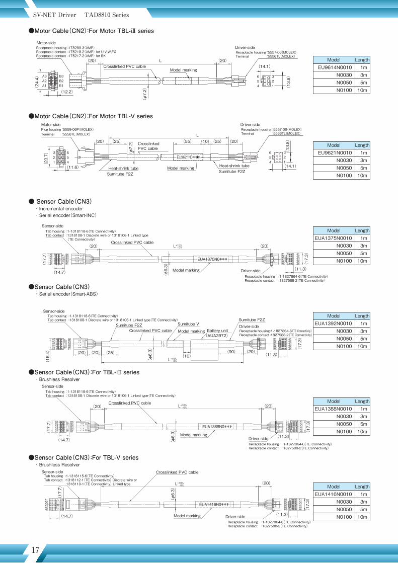
17 18
SV-NET Driver TAD8810 Series SV-NET Driver TAD8810 Series
Model marking
B1B2B3B4B5B6
A1A2A3A4A5A6
EUA1375N0***
Driver-sideReceptacle housing :1-1827864-6(TE Connectivity)Receptacle contact :1827588-2(TE Connectivity)
Sensor-sideTab housing :1-1318118-6(TE Connectivity)Tab contact :1318108-1 Discrete wire or 1318106-1 Linked type (TE Connectivity)
Crosslinked PVC cable(20) (20)
(11.3)
(17
.3)
(φ
6.3)(
17.7
)
(14.7)
L+10%- 0%
● Sensor Cable(CN3)・Incremental encoder・Serial encoder(Smart-INC)
●Sensor Cable(CN3)・Serial encoder(Smart-ABS)
(24
.4)
(φ
7.2) (
13.8
)A3A2A1
B3B2B1
654
321
(12.2)
(23
.7) (
13.8
)
(φ
7.2)
321
654
321
654
(11.6) (14.1)
(20) (20)(25) Crosslinked PVC cable
Heat-shrink tube Model marking Heat-shrink tubeSumitube F2ZSumitube F2Z
(55) (10)(25)
(20) (20)(14.1)
L
L
Crosslinked PVC cableModel marking
●Motor Cable(CN2):For Motor TBL-iⅡ series
●Motor Cable(CN2):For Motor TBL-V series
Motor-sideReceptacle housing :178289-3(AMP)Receptacle contact :175218-2(AMP) for U,V,W,FGReceptacle contact :175217-2(AMP) for BK
Motor-sidePlug housing :5559-06P(MOLEX)Terminal :5558TL(MOLEX)
Driver-sideReceptacle housing :5557-06(MOLEX)Terminal :5556TL(MOLEX)
Driver-sideReceptacle housing :5557-06(MOLEX)Terminal :5556TL(MOLEX)
Sumitube F2Z
Battery unit(AUA3972)
Sensor-sideTab housing :1-1318118-6(TE Connectivity)Tab contact :1318108-1 Discrete wire or 1318106-1 Linked type(TE Connectivity)
Sumitube F2ZCrosslinked PVC cable Model marking
Sumitube V Driver-sideReceptacle housing :1-1827864-6(TE Connectivity)Receptacle contact :1827588-2(TE Connectivity)
(17
.3)
(11.3)
(16
.4) (20) (20) (20)
L+10%-0%
(25)(10)
(φ
6.3) (90)
ModelEU9614N0010
N0030N0050N0100
1m3m5m
10m
Length
ModelEU9621N0010
N0030N0050N0100
1m3m5m
10m
Length
ModelEUA1375N0010
N0030N0050N0100
1m3m5m
10m
Length
ModelEUA1392N0010
N0030N0050N0100
1m3m5m
10m
Length
●I/O Cable
●Analog monitor Cable(CN8)
●Regenerative resistor connection cable
●Power Cable(CN1)
FLEX-B(20)7/0.127 2651PAWG#28 UL2651 or equivalentFlat Cable × 2
FX2B-40SA-1.27R(Hirose)Cable pressure contact connector
Driver-side
1
20
21
40
121
2040
※Flat cable consists of 2 pieces of 20-core cable. (They are separated between 1 to 20 pin and 21 to 40 pin of connector.)
L+10%-0%
734-105(WAGO)
2 4
Driver-sideReceptacle housing :5557-04R(MOLEX)Terminal :5556TL(MOLEX)
1 3
UL1007 AWG18 ×421
Regenerative resistor-sideHousing :5557-02R(MOLEX)Terminal :5556(MOLEX)
54321
L1+10%-0%
L2+10%-0%
(9.
4)
(14.1)
UL1007 AWG18×4
Driver-sideReceptacle housing :5557-04R(MOLEX)Terminal :5556TL(MOLEX)L
(5)
●USB Cable(CN6)
●SV-NET terminal connector(CN4/CN5) :EUA1294●Backup battery(Smart-ABS) :EUA1284●Connector set :EUA1380
Mini USB cable(SANWA SUPPLY)KU-AMB5**
(φ
4.2)
(φ
13)
(φ
13)
L±T
ModelEUA1376N0005
N0010N0030N0050
0.5m1 m3 m5 m
Length
ModelEUA1387N0010
N0020N0030
1m2m3m
Length
Model(The last 2 digits of N number)
N□□05N□□10N□□20N□□30
0.5m1 m2 m3 m
L2Length
Model(The first 2 digits of N number)EUA1417N05□□
N10□□N20□□N30□□
0.5m1 m2 m3 m
L1Length
ModelEUA1357N0010
N0030N0050N0100
1m3m5m
10m
Length
●Sensor Cable(CN3):For TBL-iⅡ series・Brushless Resolver
●Sensor Cable(CN3):For TBL-V series・Brushless Resolver
Model marking
B1B2B3B4B5B6
A1A2A3A4A5A6
EUA1388N0***
Driver-sideReceptacle housing :1-1827864-6(TE Connectivity)Receptacle contact :1827588-2(TE Connectivity)
Sensor-sideTab housing :1-1318118-6(TE Connectivity)Tab contact :1318108-1 Discrete wire or 1318106-1 Linked type(TE Connectivity)
A6A5A4A3A2A1
B6B5B4B3B2B1
Crosslinked PVC cable
(φ
6.3)
L+10%- 0%(20) (20)
(14.7)
(17
.7)
(11.3)
(17
.3)
Model marking
Crosslinked PVC cable
Driver-sideReceptacle housing :1-1827864-6(TE Connectivity)Receptacle contact :1827588-2(TE Connectivity)
EUA1416N0***
AMP
D-2
100
43
25
16
Sensor-sideTab housing :1-1318115-6(TE Connectivity)Tab contact :1318112-1(TE Connectivity) Discrete wire or 1318110-1(TE Connectivity) Linked type
(17
.3)
(11.3)
(20)L+10%- 0%
(14.7)
(17
.7)
(φ
6.3)
ModelEUA1388N0010
N0030N0050N0100
1m3m5m
10m
Length
ModelEUA1416N0010
N0030N0050N0100
1m3m5m
10m
Length
A6A5A4A3A2A1
B6B5B4B3B2B1
B1B2B3B4B5B6
A1A2A3A4A5A6
A6A5A4A3A2A1
B6B5B4B3B2B1
A1A2A3A4A5A6
B1B2B3B4B5B6
A1A2A3A4A5A6
B1B2B3B4B5B6
42
31
Housing :DF11-4DS-2C(Hirose)Crimp terminal :DF11-2428SC(Hirose)
L+10%- 0
USB A TYPE MALE MINI USB B TYPE MALE
Model
EUA1442N0010
N0018
N0030
1.0m
1.8m
3.0m
Length+0.05m‒0 +0.05m‒0 +0.10m‒0
T
3 14 2

! SAFETY PRECAUTIONSTo ensure proper and safe use of our products, please read the “SAFETY PRECAUTIONS” carefully before using them.
WARRANTYTamagawa Seiki sets a warranty period of one (1) year from the date of factory shipment, during which period we warrant
that our products are free of defects, except quality degradation by design or by accident on the part of the user. Even after
the warranty period, however, we will be willing to offer repair services necessary for maintaining the product quality. Even
though each of our products has a very long MTBF (mean time between failures) that is based on meticulous prediction, the
predictable failure rate is not zero. It is advised, therefore, that you take into account possible aftereffects due to
malfunctions of our products, and incorporate multiple safety measures in your systems and/or products so as to prevent
any consequential trouble.
'17.8Information contained in this catalog is subject to change
without notice.T12-1692N3 17.8
All information contained in this catalog is as of August. 2017.
A COMPANY OF TAMAGAWA SEIKI CO., LTD.
Headquarters:1-3-1 Haba-cho, Iida, Nagano Pref. 395-0063 JapanPHONE : +81-265-56-5423FAX : +81-265-56-5427URL : http://www.tamagawa-seiki.co.jp
■Overseas Sales Department ◆Taiwan Resident Office: 436 Bo-Ai 3rd Road, Kaohsiung City 813 Taiwan, R.O.C Mobile Phone : +886-922-0214-645 Phone&FAX : +886-7-3502257
◆TAMAGAWA EUROPE GmbH Magirus-Deutz-Str. 14,89077 Ulm Germany Phone : +49 731 96 33 89 52 FAX : +49 731 96 33 89 57
◆Representative office in USA 3838W. Carson Street, Suite 380 Torrance, California 90503 U.S.A Phone : +1-424-275-4060