access control safety light curtains - em
TRANSCRIPT

access control safety light curtains
product catalogue

Color-coding
Color-codedconnectorsfor easyinstallation
2 ACCESS CONTROL SAFETY LIGHT CURTAINS
Fully scalable Change configuration at any time
Type 4 Muting Integrated Access Control Barrier
Integrated Status and Muting lamp
Flexible configuration Hardware or Software configuration to cover all Muting applications
Vast range of accessories Including
connection boxes, special mounting
brackets and floor mouting columns
3 pre-configured Muting logics Exit-only (parallel/crossed), Entry-Exit (parallel), Entry-Exit (crossed)
Models with passive retro-reflector element
E S P E
3ACCESS CONTROL SAFETY LIGHT CURTAINS
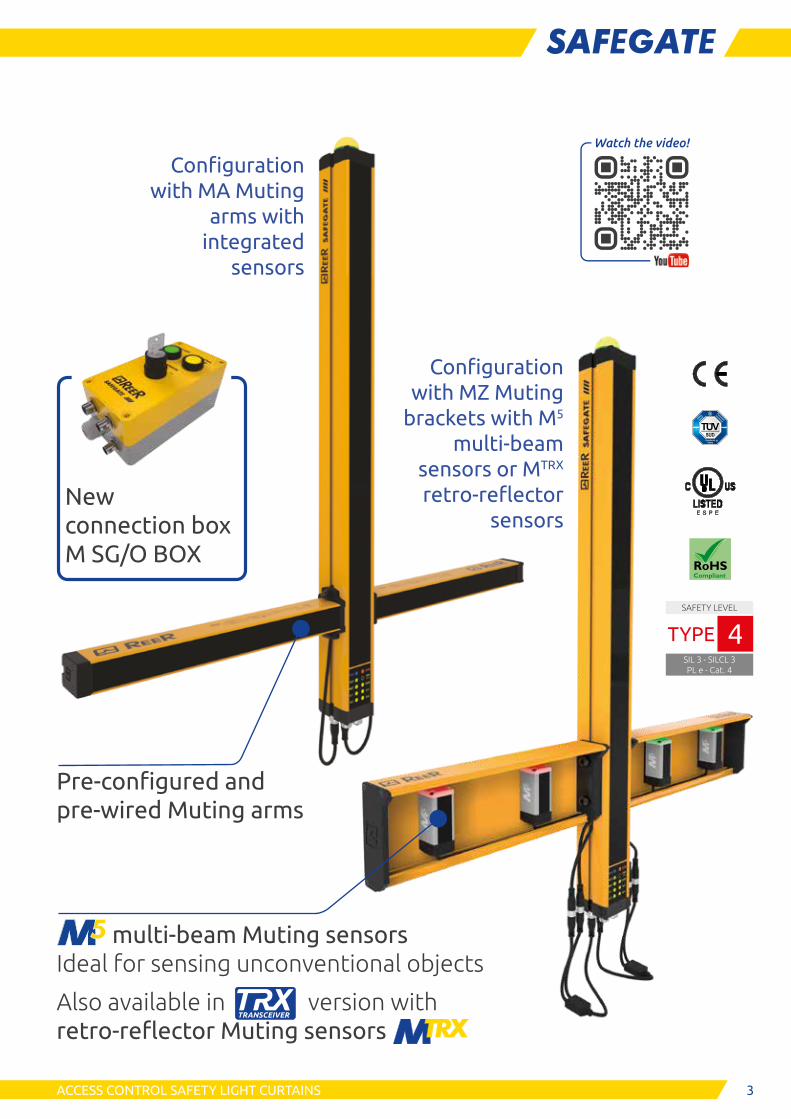
multi-beam Muting sensors Ideal for sensing unconventional objects
Also available in version with retro-reflector Muting sensors
Pre-configured and pre-wired Muting arms
Configuration with MA Muting
arms with integrated
sensors
SAFETY LEVEL
SIL 3 - SILCL 3PL e - Cat. 4
TYPE 4
New connection box M SG/O BOX
Configuration with MZ Muting
brackets with M5 multi-beam
sensors or MTRX
retro-reflector sensors

4 ACCESS CONTROL SAFETY LIGHT CURTAINS
Safegate Type 4 range of access control barriers is the ideal solution for the protection of a vast number of high-risk in-dustrial applications, in particular those requiring a high level of integration of the Muting functions.
Safegate guarantees the perfect integration of all Muting sensors, directly connected to the access control barrier
Each barrier can be configured as:
- Exit-only (L-Muting) with crossed (X) or pallalel (P) beams
- Entry-Exit (T-Muting) with crossed (X) beams
- Entry-Exit (T-Muting) with pallalel (P) beams
Configuration can be changed at any time.
Hardware configurable models (SM/SMO/SMPO) allow configuration of Muting logics and functional parameters via the Master connector wiring
Software configurable models (SMPO) allow configuration of Muting logics and additional functional parameters (i.e. Partial Muting) via Safegate Configuration Software (SCS)
Programmable models (SMPO) allow further configuration parameters, ideal to address particular issues in more complicated application scenarios
Safegate can be used with MA Muting arms (with pre-aligned and pre-configured integrated Muting sensors), with MZ Muting brackets (with M5 multi-beam photocells) or with any other Muting sensor
Sensors can be upgraded, added or removed at any time
Models with integrated status lamp allow to easily recognise the status of the barrier
Models (S) without Muting functions are also available
MAIN FEATURES
Operating temperature: -30 ... +55 °C
Protection rate: IP65 and IP67
SMPO models can be configured via the SCS software
Showing Exit-only configuration
2 crossed or parallel beams
(One-way, L-Muting)
Showing Entry-Exit configuration
2 crossed or 4 parallel beams
(Two-way, T-Muting)
Color-coded connectors for easy wiring.
5ACCESS CONTROL SAFETY LIGHT CURTAINS
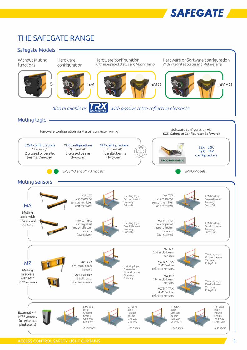
THE SAFEGATE RANGE
Safegate Models
Muting logic
Hardware configuration via Master connector wiring
L2XP configurations “Exit-only”
2 crossed or parallel beams (One-way)
T2X configurations “Entry-Exit”
2 crossed beams (Two-way)
T4P configurations “Entry-Exit”
4 parallel beams (Two-way)
Software configuration via SCS (Safegate Configurator Software)
PROGRAMMABLE
L2X, L2P, T2X, T4P
configurations
Muting sensors
MA L2X 2 integrated
sensors (emitter and receiver)
L Muting logic Crossed beams One-way Exit-only
MA T2X 2 integrated
sensors (emitter and receiver)
T Muting logic Crossed beams Two-way Entry-Exit
MA L2P TRX 2 integrated
retro-reflector sensors
(tranceiver)
L Muting logic Parallel beams One-way Exit-only
MA T4P TRX 4 integrated
retro-reflector sensors
(transceiver)
T Muting logic Parallel beams Two-way Entry-Exit
MZ L2XP 2 M5 multi-beam
sensors
MZ L2XP TRX 2 MTRX retro-
reflector sensors
L Muting logic Crossed or Parallel beams One-way Exit-only
MZ T2X 2 M5 multi-beam
sensors
MZ T2X TRX 2 MTRX retro-
reflector sensors
T Muting logic Crossed beams Two-way Entry-Exit
MZ T4P 4 M5 multi-beam
sensors
MZ T4P TRX 4 MTRX retro-
reflector sensors
T Muting logic Parallel beams Two-way Entry-Exit
MAMuting
arms with integrated
sensors
MZMuting
brackets with M5 or
MTRX sensors
L Muting logic Crossed beams One-way Exit-only 2 sensors
L Muting logic Parallel beams One-way Exit-only 2 sensors
T Muting logic Crossed beams Two-way Entry-Exit 2 sensors
T Muting logic Parallel beams Two-way Entry-Exit 4 sensors
External M⁵ , MTRX sensors (or external photocells)
Also available as with passive retro-reflective elements
SM, SMO and SMPO models SMPO Models
SM
Hardware configuration
Hardware configuration With integrated Status and Muting lamp
Hardware or Software configuration With integrated Status and Muting lamp
SMO SMPOS
Without Muting functions

6 ACCESS CONTROL SAFETY LIGHT CURTAINS
MUTING TYPES
L2X LOGIC WITH CROSSED BEAMS - ONE-WAY MUTING WITH 2 SENSORS
• Max. time between the 2 Muting activation signals: 4 sec. • Possibility to use with photocells, proximity sensors, and limit switches • Operative range: 1 ... 3,5 m (depending on Muting sensor type) • Muting sensor elements adjustable in height and angle • Max. Muting time-out time: 30 sec. or 9 hours selectable • Muting enable input available
Characteristics Suitable solution for any applications of pallet exit.
L2P LOGIC WITH PARALLEL BEAMS - ONE-WAY MUTING WITH 2 SENSORS
• Max. time between the 2 Muting activation signals: 4 sec. • Possibility to use with photocells, proximity sensors, and limit switches • Operative range: 0 ... 3,5 m (depending on Muting sensor type) • Muting sensor elements adjustable in height and angle • Max. Muting time-out time: 30 sec. or 9 hours selectable • Muting enable input available
Characteristics Suitable solution for pallet exit with transparent material applications: i.e. glass.
T2X LOGIC WITH CROSSED BEAMS - TWO-WAY MUTING WITH 2 SENSORS
• Max. time between the 2 Muting activation signals: 4 sec. • Possibility to use with photocells, proximity sensors, and limit switches • Operative range: 1 ... 3,5 m (depending on Muting sensor type) • Muting sensor elements adjustable in height and angle • Max. Muting time-out time: 30 sec. or 9 hours selectable • Muting enable input available
Characteristics Suitable solution for the most common pallet infeed/outfeed applications. Ideal solution in case of a continuous flow of pallets even without separation between the pallets.
SEQUENTIAL T4P LOGIC WITH PARALLEL BEAMS - TWO-WAY MUTING WITH 4 SENSORS
• Max. time between the 2 Muting activation signals: 4 sec. • Possibility to use with photocells, proximity sensors, and limit switches • Operative range: 0 ... 3,5 m (depending on Muting sensor type) • Muting sensor elements adjustable in height and angle • Max. Muting time-out time: 30 sec., 9 hours or infinite selectable • Muting enable input available
Characteristics Suitable solution for transparent material and application with presence of a pallet with reduced width or not centred with respect to the conveyor. Through the verification of the 4 sensors, allows to set infinite Muting time-out. Please note: this configuration needs a separation between two consecutive pallets equal to the distance between the two external Muting sensors.

7ACCESS CONTROL SAFETY LIGHT CURTAINS
PARTIAL MUTING
The SMPO programmable models allows the "Partial Muting" function, hence the possi-bility of interdicting a number of beams in relation to the size and shape of the pallet in order to prevent dangerous access when the light curtains is in muting condition.
E S P E
SAFETY LEVEL
SIL 3 - SILCL 3PL e - Cat. 4
TYPE 4
APPROVALS • 2006/42/EC: “Machine Directive” • 2014/30/EU: “Electromagnetic Compatibility Directive”
Type 4 Safety Level
• EN 61496-1:2013 “Safety of machinery - Electro-sensitive protective equipment - General requirements and tests” • EN 61496-2:2013 “Safety of machinery - Electro-sensitive protective equipment - Particular requirements for
equipment using active opto-electronic protective devices (AOPDs)"
SIL 3 Safety Level
• EN 61508-1:2010 “Functional safety of electrical/electronic programmable electronic safety related systems - General requirements”
• EN 61508-2:2010 “Functional safety of electrical/electronic/programmable electronic safety related systems - Requi-rements for electrical/electronic/programmable electronic safety-related systems”
• EN 61508-3:2010 “Functional safety of electrical/electronic programmable electronic safety related systems: Softwa-re requirements”
• EN 61508-4:2010 “Functional safety of electrical/electronic programmable electronic safety related systems - Defini-tions and abbreviations"
SILCL 3 Safety Level
• EN 62061:2005/A2:2015 “Safety of machinery - Functional safety of safety-related electrical, electronic and programmable electronic control systems”
PL e - Cat. 4 Safety Level
• EN ISO 13849-1:2015 “Safety of machinery - Safety-related parts of control systems - Part 1: General principles for design”
• UL (C+US) mark for USA and Canada • ANSI / UL 1998: “Safety Software in Programmable Components”
NOTE: Muting arms and Muting brackets are quick and easy to install. They also comply with regulatory requirements on Muting sensors geometry and all other safety-related parameters, as per IEC TS 62046 and other current standards.
Palletizer with irregular pallets transit showing a Safegate with MZ Muting brackets (M5 multi-beam photocells)

8 ACCESS CONTROL SAFETY LIGHT CURTAINS
Muting arms (MA) with pre-wired and pre-aligned sensors for all Muting logics configurations:
■ MA L2X - 2 crossed beams sensors (emitter and receiver)■ MA L2P TRX - 2 parallel beams retro-reflective sensors (TRX)■ MA L2P TRX G - 2 parallel beams retro-reflective sensors (TRX) with reduced op-
erative range to optimise correct detection of transparent materials (i.e. glass)■ MA L2P TRX V - 2 parallel beams retro-reflective sensors (TRX) with longer
Muting arms for high-speed conveyors■ MA T2X - 2 crossed beams sensors (emitter and receiver)■ MA T4P TRX - 4 parallel beams retro-reflective sensors (TRX)■ MA T4P TRX G - 4 parallel beams retro-reflective sensors (TRX) with reduced op-
erative range to optimise correct detection of transparent materials (i.e. glass)■ MA L4P TRX V - 4 parallel beams retro-reflective sensors (TRX) with longer
Muting arms for high-speed conveyors
Muting brackets (MZ) with M⁵ multi-beam sensors for all Muting logics configurations:
■ MZ L2XP / MZ L2XP H - 2 M5 or M5H sensors (H version with range up to 5 m). Ac-ting on the position of the sensors, it can be configured with crossed or parallel beams
■ MZ L2P V - 2 M5 sensors with parallel beams with longer brackets available for high-speed conveyors
■ MZ T2X / MZ T2X H - 2 M5 or M5H sensors (H version with range up to 5 m) with crossed beams
■ MZ T4P / MZ T4P H - 4 M5 or M5H sensors (H version with range up to 5 m) with parallel beams
■ MZ T4P V - 4 M5 sensors with parallel beams with longer brackets for high-speed conveyors
Muting brackets (MZ) with MTRX retro-reflector single beams sensors for all Muting logics configurations:
■ MZ L2XP TRX / MZ L2XP TRX H - 2 MTRX sensors. Acting on the position of the sensors, it can be configured with crossed or parallel beams. H version with range up to 5 m using the CD8 reflector.
■ MZ L2P TRX G - 2 MTRX sensors with parallel beams with reduced operative range to optimise correct detection of transparent materials (i.e. glass)
■ MZ T2X TRX / MZ T2X TRX H - 2 MTRX sensors with crossed beams. H version with range up to 5 m using the CD8 reflector.
■ MZ T4P TRX / MZ T4P TRX H - 4 MTRX sensors with parallel beams. H version with range up to 5 m using the CD8 reflector.
■ MZ T4P TRX G - 4 MTRX sensors with parallel beams with reduced operative range to optimise correct detection of transparent materials (i.e. glass)
MUTING SENSORS
Four muting inputs integrated into two muting connectors (red and blue)*.
Muting sensor connector (M12 5-pole)
Muting sensor connector (M12 5-pole)
M12 5-pole Y-splitter to for the connection of 2 Muting sensors on each connector
MA
MA TRX
MZ
MZ TRX
*When 4 Muting sensors are installed, the use of a Y-splitter is mandatory
9
E S P E
ACCESS CONTROL SAFETY LIGHT CURTAINS
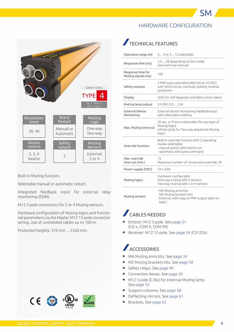
SMHARDWARE CONFIGURATION
TECHNICAL FEATURES
Operative range (m) 0 ... 4 or 3 ... 12 selectable
Response time (ms)5,5 ... 28 depending on the model (see technical manual)
Response time for Muting signals (ms)
100
Safety outputs2 PNP auto-controlled (400 mA at 24 VDC) with short-circuit, overload, polarity reversal protection
Display LEDs for self-diagnosis and light curtain status
Muting lamp output 24 VDC; 0,5 ... 5 W
External Device Monitoring
External device monitoring feedback input with selectable enabling
Max. Muting time-out
30 sec. or 9 hours selectable (for any type of Muting logic). Infinite (only for Two-way sequential Muting logic)
Override function
Built-in override function with 2 operating modes selectable: - manual action with hold to run - automatic with pulse command
Max. override time-out (min.)
15 Maximum number of consecutive override: 30
Power supply (VDC) 24 ± 20%
Muting logicsHardware configurable One-way muting with 2 sensors Two-way muting with 2 or 4 sensors
Muting sensors
- MA Muting arms kits - MZ Muting brackets kits - External, with relay or PNP output (dark-on logic)
CABLES NEEDED■ Emitter: M12 5-pole. See page 51
(CD x, CDM 9, CDM 99)■ Receiver: M12 12-pole. See page 54 (CS12Dx)
ACCESSORIES■ MA Muting arms kits. See page 34■ MZ Muting brackets kits. See page 38■ Safety relays. See page 49■ Connection boxes. See page 50■ M12 5-pole (CJSx) for external Muting lamp.
See page 55■ Support columns. See page 58■ Deflecting mirrors. See page 61■ Brackets. See page 62
Built-in Muting function.
Selectable manual or automatic restart.
Integrated feedback input for external relay monitoring (EDM).
M12 5-pole connectors for 2 or 4 Muting sensors.
Hardware configuration of Muting logics and functio-nal parameters via the Master M12 12-pole connector wiring. Use of unshielded cables up to 100 m.
Protected heights: 310 mm ... 2260 mm.
SAFETY LEVEL
SIL 3 - SILCL 3PL e - Cat. 4
TYPE 4
Resolution (mm)
30, 40
Start/ Restart
Manual or Automatic
Access control
2, 3, 4 beams
Safety output
2
Muting Logic
One-way Two-way
Muting Sensors
External 2 or 4

10 ACCESS CONTROL SAFETY LIGHT CURTAINS
SMHARDWARE CONFIGURATION
CONNECTORS
PART NUMBERS
Hand detection Max. range: selectable 4 or 12 m
SM Resolution 30 mm
SM 303
SM 453
SM 603
SM 753
SM 903
SM 1053
SM 1203
SM 1353
SM 1503
SM 1653
SM 1803
SM 1953
SM 2103
SM 2253
Ordering codes 1390221 1390222 1390223 1390224 1390225 1390226 1390227 1390228 1390229 1390230 1390231 1390232 1390233 1390234
Protected height (mm) 310 460 610 760 910 1060 1210 1360 1510 1660 1810 1960 2110 2260
Number of beams 16 23 31 38 46 53 61 68 76 83 91 98 106 113
Overall height (mm) 395 545 695 845 995 1145 1295 1445 1595 1745 1895 2045 2195 2345
SM Resolution 40 mm
SM 304
SM 454
SM 604
SM 754
SM 904
SM 1054
SM 1204
SM 1354
SM 1504
SM 1654
SM 1804
SM 1954
SM 2104
SM 2254
Ordering codes 1390321 1390322 1390323 1390324 1390325 1390326 1390327 1390328 1390329 1390330 1390331 1390332 1390333 1390334
Protected height (mm) 310 460 610 760 910 1060 1210 1360 1510 1660 1810 1960 2110 2260
Number of beams 11 16 21 26 31 36 41 46 51 56 61 66 71 76
Overall height (mm) 395 545 695 845 995 1145 1295 1445 1595 1745 1895 2045 2195 2345
Access control Max. range: selectable 4 or 12 m
SM 2, 3, 4 beamsSM 2B
SM 3B
SM 4B
Ordering codes 1390620 1390621 1390622
Number of beams 2 3 4
Beam spacing (mm) 500 400 300
Protected height (mm) 510 810 910
Overall height (mm) 685 985 1085
21
4
3 5
1 - 24 VDC 2 - RANGE 0 3 - 0 VDC 4 - RANGE 1 5 - PE
Emitter M12 5-pole - Male
1 - 24 VDC_A 2 - SYNCRO_A 3 - 0 VDC 4 - 0 VDC 5 - PE
Muting sensors 1 - 2 (blu) M12 5-pole - Female
1 - 24 VDC_B 2 - SYNCRO_B 3 - 0 VDC 4 - 0 VDC 5 - PE
Muting sensors 3 - 4 (red) M12 5-pole - Female
3
21
45
123
54
21
4
3 5
32
1
45
1 - 24 VDC 2 - Sensor 4 3 - 0 VDC 4 - Sensor 3 5 - PE
Muting sensors 3 - 4 (red) M12 5-pole - Female
1 - 24 VDC 2 - Sensor 2 3 - 0 VDC 4 - Sensor 1 5 - PE
Muting sensors 1 - 2 (blu) M12 5-pole - Female
10198
7
126
1154
32
Receiver M12 12-pole - Male
1 - 24 VDC 2 - 0 VDC 3 - OSSD 1 4 - OSSD 2 5 - PE 6 - SEL_A / Partial_Control 7 - MUT_ENABLE 8 - EDM 9 - OVERRIDE 2 10 - OVERRIDE 1/ RESTART 11 - SEL_B 12 - STATUS
1 2
5
3
3
1 - MUT_LAMP 2 - nc 3 - 0 VDC 4 - nc 5 - nc
External Muting lamp M12 5-pole - Female
M5, MTRX and MA Muting arms are set to avoid interference
Light curtain's Muting Sensor connectors can also allow the direct connection of external photocells
SYNCRO
11
E S P E
ACCESS CONTROL SAFETY LIGHT CURTAINS
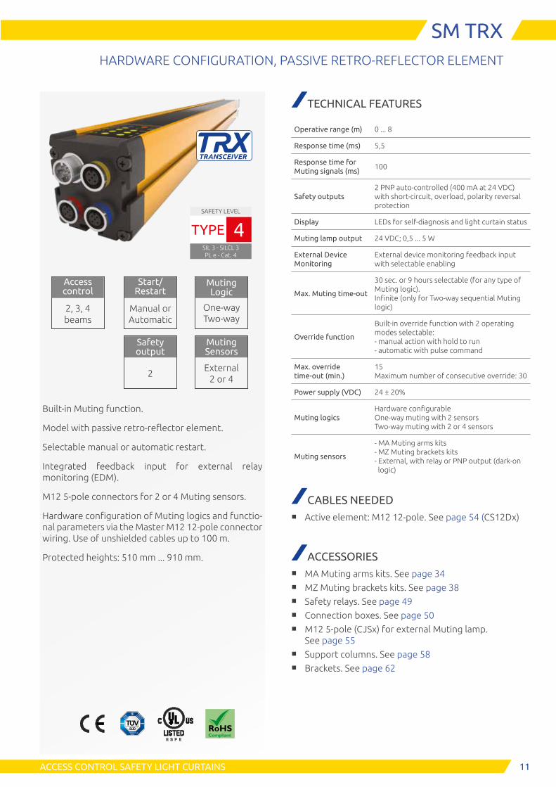
SM TRXHARDWARE CONFIGURATION, PASSIVE RETRO-REFLECTOR ELEMENT
SAFETY LEVEL
SIL 3 - SILCL 3PL e - Cat. 4
TYPE 4
Start/ Restart
Manual or Automatic
Access control
2, 3, 4 beams
Safety output
2
Muting Logic
One-way Two-way
Muting Sensors
External 2 or 4
Built-in Muting function.
Model with passive retro-reflector element.
Selectable manual or automatic restart.
Integrated feedback input for external relay monitoring (EDM).
M12 5-pole connectors for 2 or 4 Muting sensors.
Hardware configuration of Muting logics and functio-nal parameters via the Master M12 12-pole connector wiring. Use of unshielded cables up to 100 m.
Protected heights: 510 mm ... 910 mm.
TECHNICAL FEATURES
Operative range (m) 0 ... 8
Response time (ms) 5,5
Response time for Muting signals (ms)
100
Safety outputs2 PNP auto-controlled (400 mA at 24 VDC) with short-circuit, overload, polarity reversal protection
Display LEDs for self-diagnosis and light curtain status
Muting lamp output 24 VDC; 0,5 ... 5 W
External Device Monitoring
External device monitoring feedback input with selectable enabling
Max. Muting time-out
30 sec. or 9 hours selectable (for any type of Muting logic). Infinite (only for Two-way sequential Muting logic)
Override function
Built-in override function with 2 operating modes selectable: - manual action with hold to run - automatic with pulse command
Max. override time-out (min.)
15 Maximum number of consecutive override: 30
Power supply (VDC) 24 ± 20%
Muting logicsHardware configurable One-way muting with 2 sensors Two-way muting with 2 or 4 sensors
Muting sensors
- MA Muting arms kits - MZ Muting brackets kits - External, with relay or PNP output (dark-on logic)
CABLES NEEDED■ Active element: M12 12-pole. See page 54 (CS12Dx)
ACCESSORIES■ MA Muting arms kits. See page 34■ MZ Muting brackets kits. See page 38■ Safety relays. See page 49■ Connection boxes. See page 50 ■ M12 5-pole (CJSx) for external Muting lamp.
See page 55■ Support columns. See page 58■ Brackets. See page 62

21
4
3
5
32
1
4
5
1 - 24 VDC 2 - Sensor 4 3 - 0 VDC 4 - Sensor 3 5 - PE
Muting sensors 3 - 4 (red) M12 5-pole - Female
1 - 24 VDC 2 - Sensor 2 3 - 0 VDC 4 - Sensor 1 5 - PE
Muting sensors 1 - 2 (blu) M12 5-pole - Female
10198
7
126
1154
32
Active element M12 12-pole - Male
1 - 24 VDC 2 - 0 VDC 3 - OSSD 1 4 - OSSD 2 5 - PE 6 - SEL_A / Partial_Control 7 - MUT_ENABLE 8 - EDM 9 - OVERRIDE 2 10 - OVERRIDE 1/ RESTART 11 - SEL_B 12 - STATUS
1 2
5
3
1 - MUT_LAMP 2 - nc 3 - 0 VDC 4 - nc 5 - nc
External Muting lamp M12 5-pole - Female
4
12
SM TRXHARDWARE CONFIGURATION, PASSIVE RETRO-REFLECTOR ELEMENT
CONNECTORS
PART NUMBERS
Access control Max. range: 8 m
SM TRX 2, 3, 4 beams SM 2B TRX SM 3B TRX SM 4B TRX
Ordering codes 1390630 1390631 1390632
Number of beams 2 3 4
Beam spacing (mm) 500 400 300
Protected height (mm) 510 810 910
Overall height (mm) 685 985 1085
Light curtain's Muting Sensor connectors can also allow the direct connection of external photocells
ACCESS CONTROL SAFETY LIGHT CURTAINS

13
E S P E
STATUS LAMP
ACCESS CONTROL SAFETY LIGHT CURTAINS
SMOHARDWARE CONFIGURATION, WITH INTEGRATED STATUS AND MUTING LAMP
Resolution (mm)
30 - 40
Start/ Restart
Manual or Automatic
Access control
2, 3, 4 beams
Safety output
2
Muting Logic
One-way Two-way
Muting Sensors
External 2 or 4
SAFETY LEVEL
SIL 3 - SILCL 3PL e - Cat. 4
TYPE 4
Built-in Muting function.
Selectable manual or automatic restart .
Integrated feedback input for external relay monitoring (EDM).
Integrated Status and Muting lamp.
M12 5-pole connectors for 2 or 4 Muting sensors.
Hardware configuration of Muting logics and functio-nal parameters via the Master M12 12-pole connector wiring. Use of unshielded cables up to 100 m.
Protected heights: 310 mm ... 2260 mm.
TECHNICAL FEATURES
Operative range (m) 0 ... 4 or 3 ... 12 selectable
Response time (ms)5,5 ... 28 depending on the model (see technical manual)
Response time for Muting signals (ms)
100
Safety outputs2 PNP auto-controlled (400 mA at 24 VDC) with short-circuit, overload, polarity reversal protection
Display LEDs for self-diagnosis and light curtain status
Muting lamp output 24 VDC; 0,5 ... 5 W
Integrated Status and Muting lamp
Multicolor LED
External Device Monitoring
External device monitoring feedback input with selectable enabling
Max. Muting time-out
30 sec. or 9 hours selectable (for any type of Muting logic). Infinite (only for Two-way sequential Muting logic)
Override function
Built-in override function with 2 operating modes, selectable: - manual action with hold to run - automatic with pulse command
Max. override time-out (min.)
15 Maximum number of consecutive override: 30
Power supply (VDC) 24 ± 20%
Muting logicsHardware configurable One-way muting with 2 sensors Two-way muting with 2 or 4 sensors
Muting sensors
- MA Muting arms kits - MZ Muting brackets kits - External, with relay or PNP output (dark-on logic)
CABLES NEEDED■ Emitter: M12 5-pole. See page 51
(CD x, CDM 9, CDM 99)■ Receiver: M12 12-pole. See page 54 (CS12Dx)
ACCESSORIES■ MA Muting arms kits. See page 34■ MZ Muting brackets kits. See page 38■ Safety relays. See page 49■ Connection boxes. See page 50■ M12 5-pole (CJSx) for external Muting lamp.
See page 55■ Support columns. See page 58■ Deflecting mirrors. See page 61■ Brackets. See page 62

14 ACCESS CONTROL SAFETY LIGHT CURTAINS
SMOHARDWARE CONFIGURATION, WITH INTEGRATED STATUS AND MUTING LAMP
PART NUMBERS
Hand detection Max. range: selectable 4 or 12 m
SMO Resolution 30 mm
SMO 303
SMO 453
SMO 603
SMO 753
SMO 903
SMO 1053
SMO 1203
SMO 1353
SMO 1503
SMO 1653
SMO 1803
SMO 1953
SMO 2103
SMO 2253
Ordering codes 1390241 1390242 1390243 1390244 1390245 1390246 1390247 1390248 1390249 1390250 1390251 1390252 1390253 1390254
Protected height (mm) 310 460 610 760 910 1060 1210 1360 1510 1660 1810 1960 2110 2260
Number of beams 16 23 31 38 46 53 61 68 76 83 91 98 106 113
Overall height (mm) 420 570 720 870 1020 1170 1320 1470 1620 1770 1920 2070 2220 2370
SMO Resolution 40 mm
SMO 304
SMO 454
SMO 604
SMO 754
SMO 904
SMO 1054
SMO 1204
SMO 1354
SMO 1504
SMO 1654
SMO 1804
SMO 1954
SMO 2104
SMO 2254
Ordering codes 1390341 1390342 1390343 1390344 1390345 1390346 1390347 1390348 1390349 1390350 1390351 1390352 1390353 1390354
Protected height (mm) 310 460 610 760 910 1060 1210 1360 1510 1660 1810 1960 2110 2260
Number of beams 11 16 21 26 31 36 41 46 51 56 61 66 71 76
Overall height (mm) 420 570 720 870 1020 1170 1320 1470 1620 1770 1920 2070 2220 2370
Access control Max. range: selectable 4 or 12 m
SMO 2, 3, 4 beamsSMO 2B
SMO 3B
SMO 4B
Ordering codes 1390640 1390641 1390642
Number of beams 2 3 4
Beam spacing (mm) 500 400 300
Protected height (mm) 510 810 910
Overall height (mm) 710 1010 1110
2
1
4
3 5
1 - 24 VDC 2 - RANGE 0 3 - 0 VDC 4 - RANGE 1 5 - PE
Emitter M12 5-pole - Male
1 - 24 VDC_A 2 - SYNCRO_A 3 - 0 VDC 4 - 0 VDC 5 - PE
Muting sensors 1 - 2 (blu) M12 5-pole - Female
1 - 24 VDC_B 2 - SYNCRO_B 3 - 0 VDC 4 - 0 VDC 5 - PE
Muting sensors 3 - 4 (red) M12 5-pole - Female
3
21
45
123
54
1
4
3 5
32
1
45
1 - 24 VDC 2 - Sensor 4 3 - 0 VDC 4 - Sensor 3 5 - PE
Muting sensors 3 - 4 (red) M12 5-pole - Female
1 - 24 VDC 2 - Sensor 2 3 - 0 VDC 4 - Sensor 1 5 - PE
Muting sensors 1 - 2 (blu) M12 5-pole - Female
10198
7
126
1154
32
Receiver M12 12-pole - Male
1 - 24 VDC 2 - 0 VDC 3 - OSSD 1 4 - OSSD 2 5 - PE 6 - SEL_A / Partial_Control 7 - MUT_ENABLE 8 - EDM 9 - OVERRIDE 2 10 - OVERRIDE 1/ RESTART 11 - SEL_B 12 - STATUS
1 2
5
3
3
1 - MUT_LAMP 2 - nc 3 - 0 VDC 4 - nc 5 - nc
External Muting lamp M12 5-pole - Female
CONNECTORS
2
M5, MTRX and MA Muting arms are set to avoid interference.
SYNCRO Light curtain's Muting Sensor connectors can also allow the direct connection of external photocells
15ACCESS CONTROL SAFETY LIGHT CURTAINS
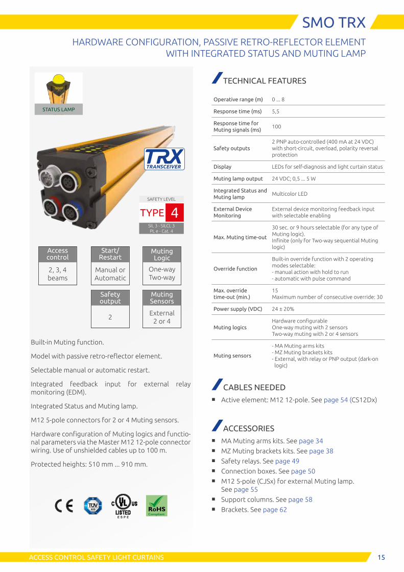
SMO TRXHARDWARE CONFIGURATION, PASSIVE RETRO-REFLECTOR ELEMENT
WITH INTEGRATED STATUS AND MUTING LAMP
STATUS LAMP
SAFETY LEVEL
SIL 3 - SILCL 3PL e - Cat. 4
TYPE 4
Start/ Restart
Manual or Automatic
Access control
2, 3, 4 beams
Safety output
2
Muting Logic
One-way Two-way
Muting Sensors
External 2 or 4
Built-in Muting function.
Model with passive retro-reflector element.
Selectable manual or automatic restart.
Integrated feedback input for external relay monitoring (EDM).
Integrated Status and Muting lamp.
M12 5-pole connectors for 2 or 4 Muting sensors.
Hardware configuration of Muting logics and functio-nal parameters via the Master M12 12-pole connector wiring. Use of unshielded cables up to 100 m.
Protected heights: 510 mm ... 910 mm.
E S P E
TECHNICAL FEATURES
Operative range (m) 0 ... 8
Response time (ms) 5,5
Response time for Muting signals (ms)
100
Safety outputs2 PNP auto-controlled (400 mA at 24 VDC) with short-circuit, overload, polarity reversal protection
Display LEDs for self-diagnosis and light curtain status
Muting lamp output 24 VDC; 0,5 ... 5 W
Integrated Status and Muting lamp
Multicolor LED
External Device Monitoring
External device monitoring feedback input with selectable enabling
Max. Muting time-out
30 sec. or 9 hours selectable (for any type of Muting logic). Infinite (only for Two-way sequential Muting logic)
Override function
Built-in override function with 2 operating modes selectable: - manual action with hold to run - automatic with pulse command
Max. override time-out (min.)
15 Maximum number of consecutive override: 30
Power supply (VDC) 24 ± 20%
Muting logicsHardware configurable One-way muting with 2 sensors Two-way muting with 2 or 4 sensors
Muting sensors
- MA Muting arms kits - MZ Muting brackets kits - External, with relay or PNP output (dark-on logic)
CABLES NEEDED■ Active element: M12 12-pole. See page 54 (CS12Dx)
ACCESSORIES■ MA Muting arms kits. See page 34■ MZ Muting brackets kits. See page 38■ Safety relays. See page 49■ Connection boxes. See page 50■ M12 5-pole (CJSx) for external Muting lamp.
See page 55■ Support columns. See page 58■ Brackets. See page 62

21
4
3
5
32
1
4
5
1 - 24 VDC 2 - Sensor 4 3 - 0 VDC 4 - Sensor 3 5 - PE
Muting sensors 3 - 4 (red) M12 5-pole - Female
1 - 24 VDC 2 - Sensor 2 3 - 0 VDC 4 - Sensor 1 5 - PE
Muting sensors 1 - 2 (blu) M12 5-pole - Female
10198
7
126
1154
32
Active element M12 12-pole - Male
1 - 24 VDC 2 - 0 VDC 3 - OSSD 1 4 - OSSD 2 5 - PE 6 - SEL_A / Partial_Control 7 - MUT_ENABLE 8 - EDM 9 - OVERRIDE 2 10 - OVERRIDE 1/ RESTART 11 - SEL_B 12 - STATUS
1 2
5
3
1 - MUT_LAMP 2 - nc 3 - 0 VDC 4 - nc 5 - nc
External Muting lamp M12 5-pole - Female
4
16 ACCESS CONTROL SAFETY LIGHT CURTAINS
SMO TRXHARDWARE CONFIGURATION, PASSIVE RETRO-REFLECTOR ELEMENT WITH INTEGRATED STATUS AND MUTING LAMP
CONNECTORS
PART NUMBERS
Access control Max. range: 8 m
SMO TRX 2, 3, 4 beams SMO 2B TRX SMO 3B TRX SMO 4B TRX
Ordering codes 1390650 1390651 1390652
Number of beams 2 3 4
Beam spacing (mm) 500 400 300
Protected height (mm) 510 810 910
Overall height (mm) 710 1010 1110
Light curtain's Muting Sensor connectors can also allow the direct connection of external photocells

17
E S P E
STATUS LAMP
ACCESS CONTROL SAFETY LIGHT CURTAINS
SMPOPROGRAMMABLE, WITH INTEGRATED STATUS AND MUTING LAMP
Built-in Muting function.
Selectable manual or automatic restart.
Integrated feedback input for external relay monitoring (EDM).
Integrated Status and Muting lamp.
M12 5-pole connectors for 2 or 4 Muting sensors.
Hardware configuration via the Master M12 12-pole connector wiring.
Software Configuration via Safegate Configura-tion Software (SCS) (PC connection with USB-M12 cable).
Use of unshielded cables up to 100 m.
Protected heights: 310 mm ... 2260 mm.
SAFETY LEVEL
SIL 3 - SILCL 3PL e - Cat. 4
TYPE 4
Resolution (mm)
30, 40
Start/ Restart
Manual or Automatic
Access control
2, 3, 4 beams
Safety output
2
Muting Logic
One-way Two-way
Muting Sensors
External 2 or 4
PROGRAMMABLE
TECHNICAL FEATURES
Operative range (m) 0 ... 4 or 3 ... 12 selectable
Response time (ms)5,5 ... 28 depending on the model (see technical manual)
Response time for Muting signals (ms)
100
Safety outputs2 PNP auto-controlled (400 mA at 24 VDC) with short-circuit, overload, polarity reversal protection
Display LEDs for self-diagnosis and light curtain status
Muting lamp output 24 VDC; 0,5 ... 5 W
Integrated Status and Muting lamp
Multicolor LED
External Device Monitoring
External device monitoring feedback input with selectable enabling
Max. Muting time-out Hardware or software configurable
Partial MutingSoftware configurable. Possibility to inhibit only a selected number of beams
Override functionBuilt-in override function with 2 operating modes. Hardware or software configurable
Max. override time-out (min.)
15 Maximum number of consecutive override: 30
Power supply (VDC) 24 ± 20%
Muting logicsHardware or software configurable One-way muting with 2 sensors Two-way muting with 2 or 4 sensors
Muting sensors
- MA Muting arms kits - MZ Muting brackets kits - External with relay or PNP output (dark-on logic)
CABLES NEEDED■ Emitter: M12 5-pole. See page 51
(CD x, CDM 9, CDM 99)■ Receiver: M12 12-pole. See page 54 (CS12Dx)■ Programming: USB-M12 5-pole adapter. See page
53 (CS12USB)
ACCESSORIES■ MA Muting arms kits. See page 34■ MZ Muting brackets kits. See page 38■ Safety relays. See page 49■ Connection boxes. See page 50■ M12 5-pole (CJSx) for external Muting lamp.
See page 55■ Support columns. See page 58■ Deflecting mirrors. See page 61■ Brackets. See page 62

18 ACCESS CONTROL SAFETY LIGHT CURTAINS
SMPOPROGRAMMABLE, WITH INTEGRATED STATUS AND MUTING LAMP
CONNECTORS
PART NUMBERS
Hand detection Max. range: selectable 4 or 12 m
SMPO Resolution 30 mm
SMPO 303
SMPO 453
SMPO 603
SMPO 753
SMPO 903
SMPO 1053
SMPO 1203
SMPO 1353
SMPO 1503
SMPO 1653
SMPO 1803
SMPO 1953
SMPO 2103
SMPO 2253
Ordering codes 1390281 1390282 1390283 1390284 1390285 1390286 1390287 1390288 1390289 1390290 1390291 1390292 1390293 1390294
Protected height (mm) 310 460 610 760 910 1060 1210 1360 1510 1660 1810 1960 2110 2260
Number of beams 16 23 31 38 46 53 61 68 76 83 91 98 106 113
Overall height (mm) 420 570 720 870 1020 1170 1320 1470 1620 1770 1920 2070 2220 2370
SMPO Resolution 40 mm
SMPO 304
SMPO 454
SMPO 604
SMPO 754
SMPO 904
SMPO 1054
SMPO 1204
SMPO 1354
SMPO 1504
SMPO 1654
SMPO 1804
SMPO 1954
SMPO 2104
SMPO 2254
Ordering codes 1390381 1390382 1390383 1390384 1390385 1390386 1390387 1390388 1390389 1390390 1390391 1390392 1390393 1390394
Protected height (mm) 310 460 610 760 910 1060 1210 1360 1510 1660 1810 1960 2110 2260
Number of beams 11 16 21 26 31 36 41 46 51 56 61 66 71 76
Overall height (mm) 420 570 720 870 1020 1170 1320 1470 1620 1770 1920 2070 2220 2370
Access control Max. range: selectable 4 or 12 m
SMPO 2, 3, 4 beamsSMPO
2BSMPO
3BSMPO
4B
Ordering codes 1390680 1390681 1390682
Number of beams 2 3 4
Beam spacing (mm) 500 400 300
Protected height (mm) 510 810 910
Overall height (mm) 710 1010 1110
2
1
4
3 5
1 - 24 VDC 2 - RANGE 0 3 - 0 VDC 4 - RANGE 1 5 - PE
Emitter M12 5-pole - Male
1 - 24 VDC_A 2 - SYNCRO_A 3 - 0 VDC 4 - 0 VDC 5 - PE
Muting sensors 1 - 2 (blu) M12 5-pole - Female
1 - 24 VDC_B 2 - SYNCRO_B 3 - 0 VDC 4 - 0 VDC 5 - PE
Muting sensors 3 - 4 (red) M12 5-pole - Female
3
2
1
45
123
54
21
4
3 5
32
1
45
1 - 24 VDC 2 - Sensor 4 3 - 0 VDC 4 - Sensor 3 5 - PE
Muting sensors 3 - 4 (red) M12 5-pole - Female
1 - 24 VDC 2 - Sensor 2 3 - 0 VDC 4 - Sensor 1 5 - PE
Muting sensors 1 - 2 (blu) M12 5-pole - Female
10198
7
126
1154
32
Receiver M12 12-pole - Male
1 - 24 VDC 2 - 0 VDC 3 - OSSD 1 4 - OSSD 2 5 - PE 6 - SEL_A / Partial_Control 7 - MUT_ENABLE 8 - EDM 9 - OVERRIDE 2 10 - OVERRIDE 1/ RESTART 11 - SEL_B 12 - STATUS
1 2
5
3
3
1 - MUT_LAMP 2 - USB + 3 - 0 VDC 4 - VBUS 5 - USB -
Programming and external Muting lamp M12 5-pole - Female
M5, MTRX and MA Muting arms are set to avoid interference.
Light curtain's Muting Sensor connectors can also allow the direct connection of external photocells
SYNCRO

19
E S P E
ACCESS CONTROL SAFETY LIGHT CURTAINS
SMPO TRXPROGRAMMABLE, PASSIVE RETRO-REFLECTOR ELEMENT
WITH INTEGRATED STATUS AND MUTING LAMP
STATUS LAMP PROGRAMMABLE
SAFETY LEVEL
SIL 3 - SILCL 3PL e - Cat. 4
TYPE 4
Start/ Restart
Manual or Automatic
Access control
2, 3, 4 beams
Safety output
2
Muting Logic
One-way Two-way
Muting Sensors
External 2 or 4
Built-in Muting function.
Model with passive retro-reflector element.
Selectable manual or automatic restart.
Integrated feedback input for external relay monitoring (EDM).
Integrated Status and Muting lamp.
M12 5-pole connectors for 2 or 4 Muting sensors.
Hardware configuration via the Master M12 12-pole connector wiring.
Software Configuration via Safegate Configura-tion Software (SCS) (PC connection with USB-M12 cable).
Use of unshielded cables up to 100 m.
Protected heights: 510 mm ... 910 mm.
TECHNICAL FEATURES
Operative range (m) 0 ... 8
Response time (ms) 5,5
Response time for Muting signals (ms)
100
Safety outputs2 PNP auto-controlled (400 mA at 24 VDC) with short-circuit, overload, polarity reversal protection
Display LEDs for self-diagnosis and light curtain status
Muting lamp output 24 VDC; 0,5 ... 5 W
Integrated Status and Muting lamp
Multicolor LED
External Device Monitoring
External device monitoring feedback input with selectable enabling
Max. Muting time-out Hardware or software configurable
Partial MutingSoftware configurable. Possibility to inhibit only a selected number of beams (3 and 4 beams only)
Override functionBuilt-in override function with 2 operating modes. Hardware or software configurable
Max. override time-out (min.)
15 Maximum number of consecutive override: 30
Power supply (VDC) 24 ± 20%
Muting logicsHardware configurable One-way muting with 2 sensors Two-way muting with 2 or 4 sensors
Muting sensors
- MA Muting arms kits - MZ Muting brackets kits - External, with relay or PNP output (dark-on logic)
CABLES NEEDED■ Active element: M12 12-pole. See page 54 (CS12Dx)■ Programming: USB-M12 5-pole adapter. See page
53 (CS12USB)
ACCESSORIES■ MA Muting arms kits. See page 34■ MZ Muting brackets kits. See page 38■ Safety relays. See page 49■ Connection boxes. See page 50■ M12 5-pole (CJSx) for external Muting lamp.
See page 55■ Support columns. See page 58■ Brackets. See page 62

21
4
3
5
32
1
4
5
1 - 24 VDC 2 - Sensor 4 3 - 0 VDC 4 - Sensor 3 5 - PE
Muting sensors 3 - 4 (red) M12 5-pole - Female
1 - 24 VDC 2 - Sensor 2 3 - 0 VDC 4 - Sensor 1 5 - PE
Muting sensors 1 - 2 (blu) M12 5-pole - Female
10198
7
126
1154
32
Active element M12 12-pole - Male
1 - 24 VDC 2 - 0 VDC 3 - OSSD 1 4 - OSSD 2 5 - PE 6 - SEL_A / Partial_Control 7 - MUT_ENABLE 8 - EDM 9 - OVERRIDE 2 10 - OVERRIDE 1/ RESTART 11 - SEL_B 12 - STATUS
1 2
5
3
1 - MUT_LAMP 2 - nc 3 - 0 VDC 4 - nc 5 - nc
External Muting lamp M12 5-pole - Female
4
20 ACCESS CONTROL SAFETY LIGHT CURTAINS
SMPO TRXPROGRAMMABLE, PASSIVE RETRO-REFLECTOR ELEMENT WITH INTEGRATED STATUS AND MUTING LAMP
CONNECTORS
PART NUMBERS
Access control Max. range: 8 m
SMPO 2, 3, 4 beams SMPO 2B TRX SMPO 3B TRX SMPO 4B TRX
Ordering codes 1390690 1390691 1390692
Number of beams 2 3 4
Beam spacing (mm) 500 400 300
Protected height (mm) 510 810 910
Overall height (mm) 710 1010 1110
Light curtain's Muting Sensor connectors can also allow the direct connection of external photocells
21ACCESS CONTROL SAFETY LIGHT CURTAINS
S
E S P E
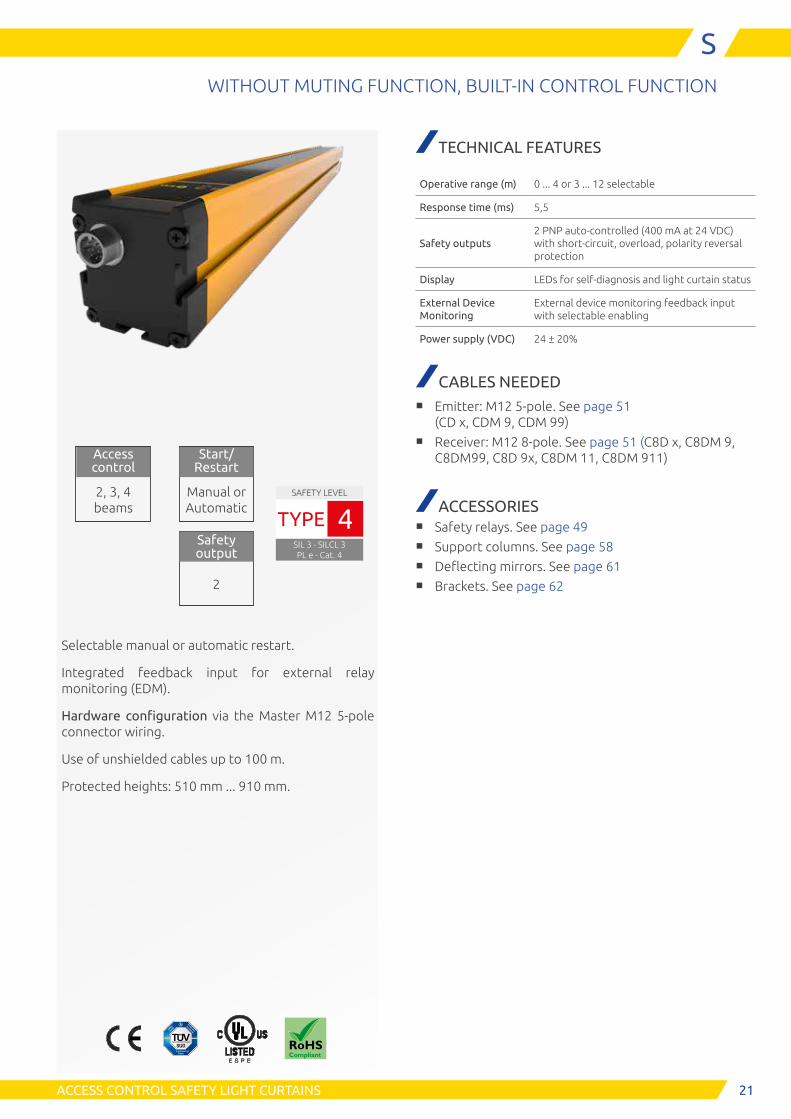
WITHOUT MUTING FUNCTION, BUILT-IN CONTROL FUNCTION
Selectable manual or automatic restart.
Integrated feedback input for external relay monitoring (EDM).
Hardware configuration via the Master M12 5-pole connector wiring.
Use of unshielded cables up to 100 m.
Protected heights: 510 mm ... 910 mm.
Start/ Restart
Manual or Automatic
Access control
2, 3, 4 beams
Safety output
2
TECHNICAL FEATURES
Operative range (m) 0 ... 4 or 3 ... 12 selectable
Response time (ms) 5,5
Safety outputs2 PNP auto-controlled (400 mA at 24 VDC) with short-circuit, overload, polarity reversal protection
Display LEDs for self-diagnosis and light curtain status
External Device Monitoring
External device monitoring feedback input with selectable enabling
Power supply (VDC) 24 ± 20%
CABLES NEEDED■ Emitter: M12 5-pole. See page 51
(CD x, CDM 9, CDM 99)■ Receiver: M12 8-pole. See page 51 (C8D x, C8DM 9,
C8DM99, C8D 9x, C8DM 11, C8DM 911)
ACCESSORIES■ Safety relays. See page 49■ Support columns. See page 58■ Deflecting mirrors. See page 61■ Brackets. See page 62
SAFETY LEVEL
SIL 3 - SILCL 3PL e - Cat. 4
TYPE 4

22 ACCESS CONTROL SAFETY LIGHT CURTAINS
SWITHOUT MUTING FUNCTION, BUILT-IN CONTROL FUNCTION
1 - 24 Vcc 2 - RANGE 0 3 - 0 Vcc 4 - RANGE 1 5 - PE
Emitter M12 5-pole - Male
12
354
1
8
7
6
5
4
32
Receiver M12 8-pole - Male
1 - OSSD 1 2 - 24 Vcc 3 - OSSD 2 4 - EDM 5 - SEL_A 6 - SEL_B 7 - 0 Vcc 8 - PE
CONNECTORS
PART NUMBERS
Access control Max. range: selectable 4 or 12 m
S 2, 3, 4 beams S 2B S 3B S 4B
Ordering codes 1390600 1390601 1390602
Number of beams 2 3 4
Beam spacing (mm) 500 400 300
Protected height (mm) 510 810 910
Overall height (mm) 685 985 1085

23
E S P E
ACCESS CONTROL SAFETY LIGHT CURTAINS
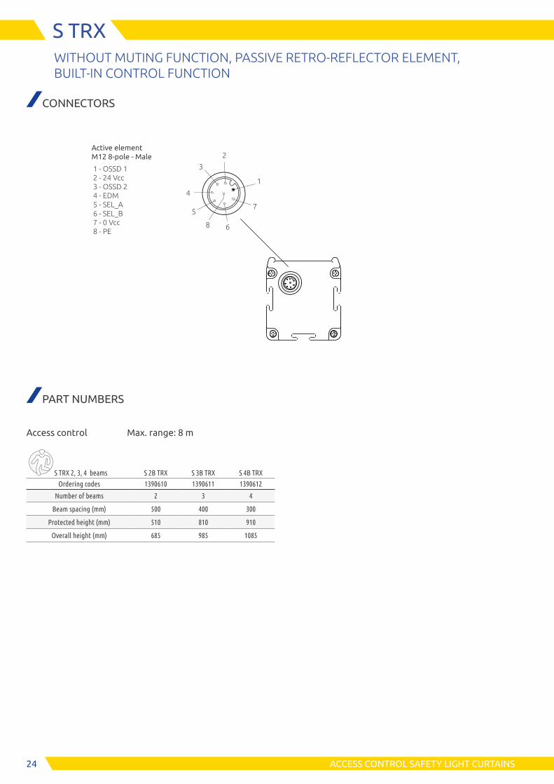
S TRXWITHOUT MUTING FUNCTION, PASSIVE RETRO-REFLECTOR ELEMENT,
BUILT-IN CONTROL FUNCTION
SAFETY LEVEL
SIL 3 - SILCL 3PL e - Cat. 4
TYPE 4
Start/ Restart
Manual or Automatic
Access control
2, 3, 4 beams
Safety output
2
Model with passive retro-reflector element.
Selectable manual or automatic restart.
Integrated feedback input for external relay monitoring (EDM).
Hardware configuration via the Master M12 8-pole connector wiring. Use of unshielded cables up to 100 m.
Protected heights: 510 mm ... 910 mm.
TECHNICAL FEATURES
Operative range (m) 0 ... 8
Response time (ms) 5,5
Safety outputs2 PNP auto-controlled (400 mA at 24 VDC) with short-circuit, overload, polarity reversal protection
Display LEDs for self-diagnosis and light curtain status
External Device Monitoring
External device monitoring feedback input with selectable enabling
Power supply (VDC) 24 ± 20%
CABLES NEEDED■ Active element: M12 8-pole. See page 51 (C8D x,
C8DM 9, C8DM99, C8D 9x, C8DM 11, C8DM 911)
ACCESSORIES■ Safety relays. See page 49■ Support columns. See page 58■ Connection boxes. See page 50■ Brackets. See page 62
24 ACCESS CONTROL SAFETY LIGHT CURTAINS
S TRXWITHOUT MUTING FUNCTION, PASSIVE RETRO-REFLECTOR ELEMENT, BUILT-IN CONTROL FUNCTION
CONNECTORS
Active element M12 8-pole - Male
PART NUMBERS
Access control Max. range: 8 m
S TRX 2, 3, 4 beams S 2B TRX S 3B TRX S 4B TRX
Ordering codes 1390610 1390611 1390612
Number of beams 2 3 4
Beam spacing (mm) 500 400 300
Protected height (mm) 510 810 910
Overall height (mm) 685 985 1085
1
8
7
6
5
4
3
2
1 - OSSD 1 2 - 24 Vcc 3 - OSSD 2 4 - EDM 5 - SEL_A 6 - SEL_B 7 - 0 Vcc 8 - PE
25
E S P E
ACCESS CONTROL SAFETY LIGHT CURTAINS
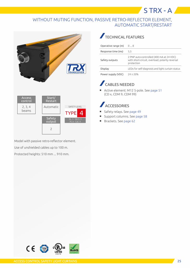
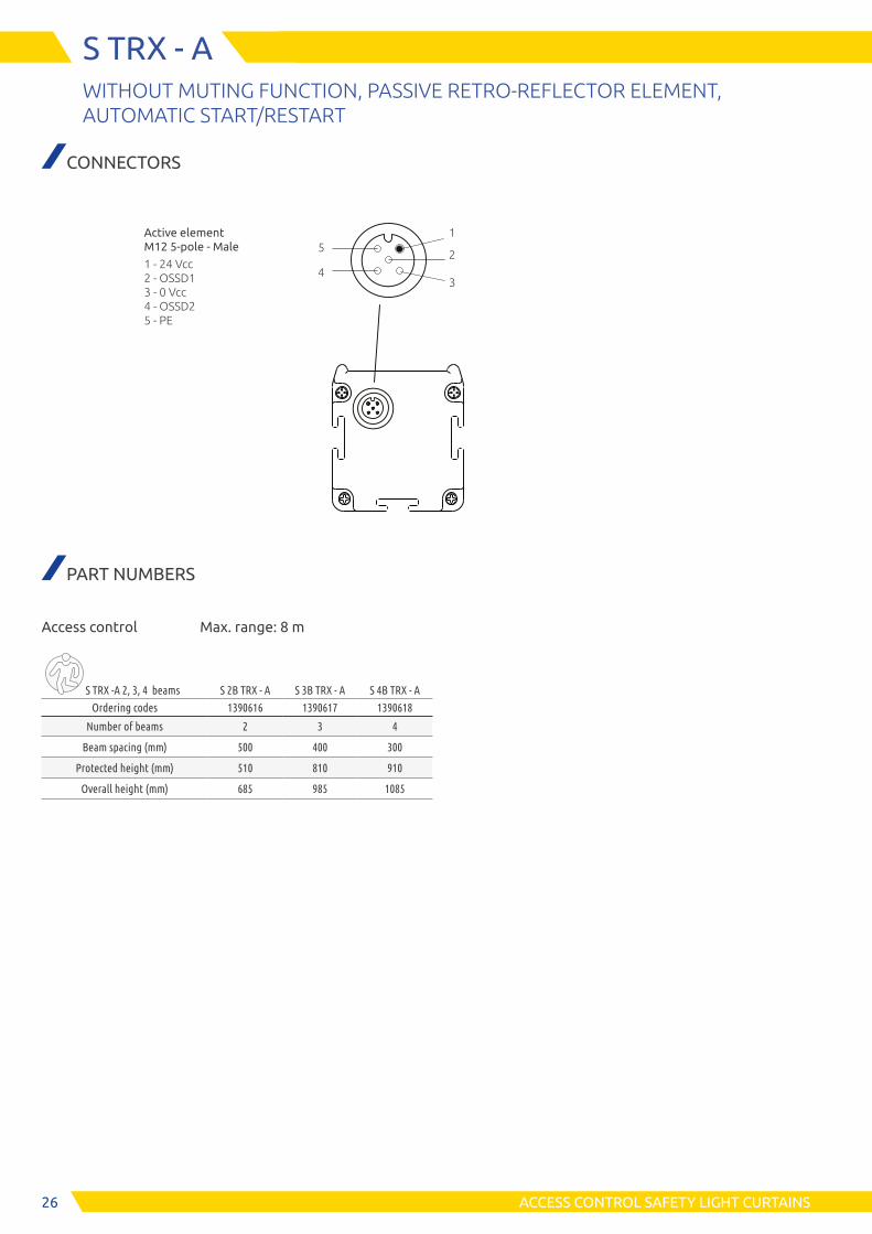
S TRX - AWITHOUT MUTING FUNCTION, PASSIVE RETRO-REFLECTOR ELEMENT,
AUTOMATIC START/RESTART
SAFETY LEVEL
SIL 3 - SILCL 3PL e - Cat. 4
TYPE 4
Start/ Restart
Automatic
Access control
2, 3, 4 beams
Safety output
2
Model with passive retro-reflector element.
Use of unshielded cables up to 100 m.
Protected heights: 510 mm ... 910 mm.
TECHNICAL FEATURES
Operative range (m) 0 ... 8
Response time (ms) 5,5
Safety outputs2 PNP auto-controlled (400 mA at 24 VDC) with short-circuit, overload, polarity reversal protection
Display LEDs for self-diagnosis and light curtain status
Power supply (VDC) 24 ± 20%
CABLES NEEDED■ Active element: M12 5-pole. See page 51
(CD x, CDM 9, CDM 99)
ACCESSORIES■ Safety relays. See page 49■ Support columns. See page 58■ Brackets. See page 62
26 ACCESS CONTROL SAFETY LIGHT CURTAINS
S TRX - AWITHOUT MUTING FUNCTION, PASSIVE RETRO-REFLECTOR ELEMENT, AUTOMATIC START/RESTART
CONNECTORS
Active element M12 5-pole - Male
1 - 24 Vcc 2 - OSSD1 3 - 0 Vcc 4 - OSSD2 5 - PE
15
43
2
PART NUMBERS
Access control Max. range: 8 m
S TRX -A 2, 3, 4 beams S 2B TRX - A S 3B TRX - A S 4B TRX - A
Ordering codes 1390616 1390617 1390618
Number of beams 2 3 4
Beam spacing (mm) 500 400 300
Protected height (mm) 510 810 910
Overall height (mm) 685 985 1085

27ACCESS CONTROL SAFETY LIGHT CURTAINS
MECHANICAL DATA
EMITTER - RECEIVER MODELS (S, SM, SMO AND SMPO)
Model 300 450 600 750 900 1050 1200 1350 1500 1650 1800 1950 2100 2250 2B 3B 4B
A1 (mm) 420 570 720 870 1020 1170 1320 1470 1620 1770 1920 2070 2220 2370 710 1010 1110
A2 (mm) 395 545 695 845 995 1145 1295 1445 1595 1745 1895 2045 2195 2345 685 985 1085
B (mm) 300 450 600 750 900 1050 1200 1350 1500 1650 1800 1950 2100 2250 590 890 990
Mounting Set of 4 brackets included Set of 6 brackets includedSet of 4 brackets
included
50
55
10,5
B
A2
66,5
Receiver
A1
With integrated Status and Muting lamp
10,5
72
Top
50
55
Top
72
66,5
50
55
50
55
TopTop
10,5
10,5
112
112
A2A1B B B
Access control models (2, 3, 4 beams)
Hand detection models (resolution 30, 40 mm)
66,5
66,5
Emitter Receiver Emitter
With integrated Status and Muting lamp
Note: S models without Muting sensor and lamp connectors

28 TECHNICAL FEATURES
50
55
50
55
TopTop
10,5
112
112
A2A1 B B
Access control models (2, 3, 4 beams)
66,5
66,5
Active element
Passive element
With integrated Status and Muting lamp
TRX MODELS (S, SM, SMO AND SMPO)
Model 2B 3B 4B
A1 (mm) 710 1010 1110
A2 (mm) 685 985 1085
B (mm) 590 890 990
MountingSet of 4 brackets
included
Note: S models without Muting sensor and lamp connectors

29
Maximum vertical adjustment allowed: ± 70 mm
Maximum angular adjustment allowed: ± 8°
Maximum vertical adjustment allowed: ± 70 mm
Maximum angular adjustment allowed: ± 8°
Maximum angular adjustment allowed: ± 8°
TECHNICAL FEATURES
MA and MA TRXMuting arms
MZ and MZ TRX Muting brackets
SENSORS ADJUSTMENT
All MA Muting arms are adjustable in height and angle.
This unique feature, allows to control the angle of the detection plane, facilitating the detection of irregular materials in transit.
The reference ruler on the side of the barrier facilitates the alignment of the arms.
MZ Muting brackets with M5 multi-beams or MTRX re-tro-reflection photocells, in addition to the height and angular adjustment, also allow angular adjustment of the M5 / MTRX sensors on their vertical axis.
MZ brackets are equipped with 2 fixing rails for Muting sensors. One allows angular adjustments, the other no. By using this second track to fix the Muting sensors, alignment is achieved automatically on the normal plane of the bracket.

30 TECHNICAL FEATURES
INTEGRATED STATUS AND MUTING LAMP
Flashing
Flashing
Flashing
Flashing
GUARD Normal operations
CLEAR Waiting for restart
MUTING Muting in progress
OVERRIDE Override in progress
OVERRIDE REQUEST Waiting for an override
BREAK Occupied curtain (at least one beam occupied)
FAIL Error condition
DISPLAYEmitter SM - SMO - SMPO Models
1 - Tri-colour LED Description
Power on - Initial Test
Flashing Fail condition
Test condition
Normal operation
Receiver SM - SMO - SMPO Models Active element SM TRX - SMO TRX - SMPO TRX
PRG COM CLRLED bi-colour
MUT OVR S1 S2 S3 S4 Description
Power on - Initial Test
Regular operations
LED LED status Description
PROG Light curtain programmed via USB
COM Communication with active PC
CLR Light curtain awaiting for RESTART (clear gate)
LED bi-colourOSSD outputs set to OFF - Occupied light curtain condition
GUARD condition
MUT Muting active
OVROverride active
Flashing Override request
S1Interruption Sensor 1
Sensor 1 clear
S2Interruption Sensor 2
Sensor 2 clear
S3Interruption Sensor 3
Sensor 3 clear
S4Interruption Sensor 4
Sensor 4 clear
PRG
CLR
MUT
S 1
S 3
OVR
S 2
S 4
COM PRG
CLR
COM
PRG
CLR
MUT
S 1
S 3
OVR
S 2
S 4
COM PRG
CLR
COM

31TECHNICAL FEATURES
Fault operations
Number of flashes
DescriptionLED bi-colour CLR MUT OVR S1 S2 S3 S4
2 Configuration error SEL_A/SEL_B/EDM
3 Wrong EDM configuration
3 3 EDM feedback failure
3 3 STATUS input failure
3 3 OVERRIDE_1 / OVERRIDE_1 input failure
3 3 Sensor input failure
3 3 3 3 3 Muting lamp failure
4 OSSD1 / OSSD2 error
5 Main card error
5 5 Base sheet (EEPROM) error
5 5 Main card error
6 Main card (Microcontroller) error
6 6 Generic default board error
6 6 Beams error
6 6 24 VDC power supply overload
6 6 6 6 Lamp/status over current
7 Receiving beams failure
8 Interfering emitter detected
Receiver S model Active element S TRX - S TRX-A Model
WEAK CLRLED bi-colore
Descrizione
Power on - Initial Test
Durante il funzionamento normale
LED Stato LED Descrizione
WEAK Weak signal
CLR Light curtain awaiting for RESTART (clear gate)
LED bi-coloreOSSD outputs set to OFF - Occupied light curtain condition
GUARD condition
PRG
CLR
MUT
S 1
S 3
OVR
S 2
S 4
COM PRG
CLR
COM
PRG
CLR
MUT
S 1
S 3
OVR
S 2
S 4
COM WEAK
CLR

32 TECHNICAL FEATURES
CODE LEGEND
Resolution
3 - 30 mm 4 - 40 mm
Protected height
30x - 310 mm 105x - 1060 mm 180x - 1810 mm 45x - 460 mm 120x - 1210 mm 195x - 1969 mm 60x - 610 mm 135x - 1360 mm 210x - 2110 mm 75x - 760 mm 150x - 1510 mm 225x - 2260 mm 90x - 910 mm 165x - 1660 mm
Number of beams
2B - 2 beams 3B - 3 beams 4B - 4 beams
Status and muting lamp
O Integrated
Programmability of the light curtain
P Programmable light curtain
Emitter or receiver
E Emitter R Receiver
Palletizer with regular pallets transit showing a Safegate with MA Muting arms (integrated sensors)
Model with passive retro-reflector element
PM O E
R
30
2B
3 TRX A Automatic Start/RestartS
Funzioni di Muting Integrate

33TECHNICAL FEATURES
SAFEGATE CONFIGURATION SOFTWARE (SCS)
Software configurable models (SMPO) allow configuration of Muting logics and additional functional parameters (i.e. Partial Muting) via Safegate Configuration Software (SCS). Programmable models (SMPO) allow managing further con-figuration parameters, ideal to address particular issues in more complicated application scenarios.
Access to the programming functions of the light curtains protected by two-level password
Possibility of downloading the existing configuration of the light curtain
Uploading of the light curtain configuration
Light curtains general parameter configuration
- Automatic or manual restart - K1/K2 feedback enabling
- K1/K2 feedback reading time
Muting logic configuration - L Muting logic with parallel or
crossed beams - T Muting logic with crossed beams
- T Muting logic with parallel beams (sequential) - T Muting logic with parallel beams (concurrent)
Muting parameters configuration - Muting enable
- Occupancy order of the sensors (direction)
- Sensor gap for non-homogeneous pallet materials - Muting closure and Muting time-out
Partial Muting configuration Can be activated and configured 2
thresholds to define the number of beens in Muting condition.
Override function configuration
Check and configuration validation
Light curtain status monitoring
Status monitor
Configuration

34
70
45
70
320
Emitter Receiver
250
320
25045
35
Dimensions: mm
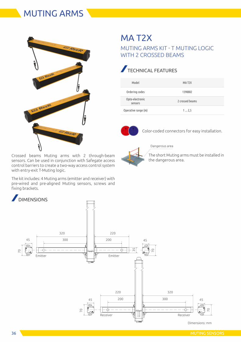
MUTING SENSORS
MUTING ARMS
Crossed beams Muting arms with 2 through-beam sensors.
Can be used in conjunction with Safegate access control barriers to create a one-way access control system with exit-only L-Muting logic.
The kit includes: 2 Muting arms (emitter and receiver) with pre-wired and pre-aligned Muting sensors, screws and fixing brackets.
MA L2XMUTING ARMS KIT - L MUTING LOGIC WITH 2 CROSSED BEAMS
TECHNICAL FEATURES
Model MA L2X
Ordering codes 1390800
Opto-electronic sensors
2 crossed beams
Operative range (m) 1 ... 2,5
DIMENSIONS
Color-coded connectors for easy installation.
The Muting arms must be installed in the dangerous area.
Dangerous area

35
Active element
35
430
120 250
Passive element
430
70
45
70
45
Dimensions: mm
Active element
35
360
50 250
Passive element
360
70
45
70
45
MA L2P TRX and MA L2P TRX G
MA L2P TRX V
MUTING SENSORS
MUTING ARMS
Parallel beams Muting arms with 2 retro-reflective sen-sors. Can be used in conjunction with Safegate access control barriers to create a one-way access control system with exit-only L-Muting logic.
The kit includes: 2 Muting arms (active and passive ele-ments) with pre-wired and pre-aligned Muting sensors, screws and fixing brackets.
Special versions
MA L2P TRX G with special built-in Muting sensors to opti-mise correct and consistent detection of transparent ma-terials (i.e. glass).
MA L2P TRX V with longer built-in Muting arms for high-speed conveyors.
MA L2P TRX / G / V / VGTRX MUTING ARMS KIT - L MUTING LOGIC WITH 2 PARALLEL BEAMS
TECHNICAL FEATURES
Model
MA L2P TRX MA L2P TRX G (transparent material) MA L2P TRX V (high-speed conveyors)
MA L2P TRX VG (high speed for transparent material)
Ordering codes
MA L2P TRX - 1390804 MA L2P TRX G - 1390813 MA L2P TRX V - 1390806
MA L2P TRX VG - 1390821
Opto-electronic sensors
2 parallel beams
Operative range (m)
0 ... 3,5 (MA L2P TRX) 0 ... 2 (MA L2P TRX G)
0 ... 3,5 (MA L2P TRX V) 0 ... 2 (MA L2P TRX VG)
DIMENSIONS
Color-coded connectors for easy installation.
The Muting arms must be installed in the dangerous area.
Dangerous area
36
220
Receiver
Emitter
35
320
300 200
70
45
70
45
Dimensions: mm
Emitter
Receiver
220
200
320
300
70
45
70
45
MUTING SENSORS
MUTING ARMS
Crossed beams Muting arms with 2 through-beam sensors. Can be used in conjunction with Safegate access control barriers to create a two-way access control system with entry-exit T-Muting logic.
The kit includes: 4 Muting arms (emitter and receiver) with pre-wired and pre-aligned Muting sensors, screws and fixing brackets.
MA T2XMUTING ARMS KIT - T MUTING LOGIC WITH 2 CROSSED BEAMS
TECHNICAL FEATURES
Model MA T2X
Ordering codes 1390802
Opto-electronic sensors
2 crossed beams
Operative range (m) 1 ... 2,5
DIMENSIONS
Color-coded connectors for easy installation.
The short Muting arms must be installed in the dangerous area.
Dangerous area
37
35
Dimensions: mm
Active element (right)
45
70
Active element (left)
430
430 430
430
250
35
Passive element (right)
Passive element (left)
Active element (right)
45
45
7070
Active element (left)
360
360 360
360
250
250
Passive element (right)
Passive element (left)
250
70
45
70
45
70
45
70
45
70
45
120 120
MA T4P TRX V
MA T4P TRX and MA T4P TRX G
50 50
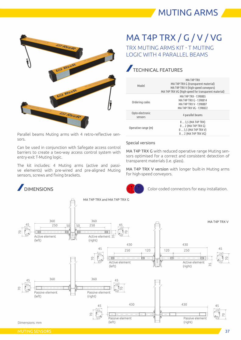
MUTING SENSORS
MUTING ARMS
Parallel beams Muting arms with 4 retro-reflective sen-sors.
Can be used in conjunction with Safegate access control barriers to create a two-way access control system with entry-exit T-Muting logic.
The kit includes: 4 Muting arms (active and passi-ve elements) with pre-wired and pre-aligned Muting sensors, screws and fixing brackets.
MA T4P TRX / G / V / VGTRX MUTING ARMS KIT - T MUTING LOGIC WITH 4 PARALLEL BEAMS
TECHNICAL FEATURES
Model
MA T4P TRX MA T4P TRX G (transparent material) MA T4P TRX V (high-speed conveyors)
MA T4P TRX VG (high-speed for transparent material)
Ordering codes
MA T4P TRX - 1390805 MA T4P TRX G - 1390814 MA T4P TRX V - 1390807
MA T4P TRX VG - 1390822
Opto-electronic sensors
4 parallel beams
Operative range (m)
0 ... 3,5 (MA T4P TRX) 0 ... 2 (MA T4P TRX G)
0 ... 3,5 (MA T4P TRX V) 0 ... 2 (MA T4P TRX VG)
Special versions
MA T4P TRX G with reduced operative range Muting sen-sors optimised for a correct and consistent detection of transparent materials (i.e. glass).
MA T4P TRX V version with longer built-in Muting arms for high-speed conveyors.
DIMENSIONS Color-coded connectors for easy installation.

38
Receiver
105
Emitter
420420
Receiver
105
Emitter
360360
18,5
250
86,5
250
7,5
60
Dimensions: mm
60 37,52,5
Ø6
11
18,5
250
86,5
250
7,5
120120 37,52,5
11 Ø6
MZ L2XP
MZ L2P V
MUTING SENSORS
MUTING BRACKETS
Crossed or parallel beams Muting brackets with 2 M5 or M5H multi-beam photocells. Can be used in conjunction with Safegate access control barriers to create a one-way access control system with exit-only L-Muting logic.
The kit includes: 2 Muting brackets with 2 M5 or M5H multi-beam photocells (emitter and receiver), screws and fixing brackets.
Special versions
MZ L2P V with longer Muting brackets for high-speed con-veyors.
MZ L2XP / H / VMUTING BRACKETS KIT - L LOGIC WITH CROSSED OR PARALLEL BEAMS
TECHNICAL FEATURES
ModelMZ L2XP
MZ L2XP H MZ L2P V (high speed conveyors)
Ordering codesMZ L2XP - 1390808
MZ L2XP H - 1390823 MZ L2XP V - 1390811
Opto-electronic sensors
MZ L2XP - 2 M5 crossed or parallel beams MZ L2XP H - 2 M5H crossed or parallel beams
MZ L2P V - 2 M5 crossed or parallel beams
Operative range (m)0 ... 3,5 (MZ L2XP and MZ L2P V)
0 ... 5 (MZ L2XP H)
NOTE
This model defaults in P (parallel beams) configuration. To change to X (crossed beams) configuration, the multi-beam photocells, on one of the brackets, must be rever-sed and re-oriented accordingly. To avoid any interference, the two M5 or M5H multi-beam photocells use different encodings.
DIMENSIONS Color-coded connectors for easy installation.

39MUTING SENSORS
MUTING BRACKETS
Crossed or parallel beams Muting brackets with 2 MTRX re-tro-reflector single-beam photocells. Can be used in con-junction with Safegate access control barriers to create a one-way access control system with exit-only L-Muting logic.
The kit includes: 2 Muting brackets with 2 MTRX retro- reflector single-beam photocells and 2 reflectors, screws and fixing brackets.
Special versions
MZ L2P TRX G with reduced operative range Muting sen-sors optimised for a correct and consistent detection of transparent materials (i.e. glass).
MZ L2XP TRX / H / GTRX MUTING BRACKETS KIT - L LOGIC WITH CROSSED OR PARALLEL BEAMS
TECHNICAL FEATURES
ModelMZ L2XP TRX
MZ L2XP TRX H MZ L2P TRX G (transparent material)
Ordering codesMZ L2XP TRX - 1390815
MZ L2XP TRX H - 1390826 MZ L2XP TRX G - 1390818
Opto-electronic sensors
2 MTRX crossed or parallel beams
Operative range (m)0 ... 3,5 (MZ L2XP TRX) 0 ... 5 (MZ L2XP TRX H) 0 ... 2 (MZ L2XP TRX G)
NOTE
This model defaults in P (parallel beams) configuration. To change to X (crossed beams) configuration, the photo-cells must be re-oriented. To avoid any interference, the two MTRX photocells use different encodings.
DIMENSIONS
Color-coded connectors for easy installation.
C8D reflectors. Range up to 5 m MZ L2XP TRX H
C3F8 reflectors. Range up to 3,5 m
MZ L2XP TRX
Active element
105
Passive element
360360
18,5
250
86,5
250
7,5
60
Dimensions: mm
60 37,52,5
Ø6
11
Passive element
360250 60
C3F8 reflectors. Range up to 3,5 m
MZ L2XP TRX
C8D reflectors. Range up to 5 m MZ L2XP TRX H

40
Receiver
Emitter 360
360
18,5
300
86,5
300
7,5
200
Dimensions: mm
240
37,52,5
11
200
240
105
Ø6
MUTING SENSORS
MUTING BRACKETS
Crossed beams Muting brackets with 2 M5 or M5H multi-beam photocells. Can be used in conjunction with Safe-gate access control barriers to create a two-way access control system with entry-exit T-Muting logic.
The kit includes: 4 Muting brackets with 2 M5 or M5H multi-beam photocells (emitter and receiver), screws and fixing brackets.
MZ T2X / HMUTING BRACKETS KIT - T LOGIC WITH CROSSED BEAMS
TECHNICAL FEATURES
ModelMZ T2X
MZ T2X H
Ordering codesMZ T2X - 1390809
MZ T2X H - 1390824
Opto-electronic sensors
2 M5 crossed beams 2 M5H crossed beams
Operative range (m)0 ... 3,5 (MZ T2X) 0 ... 5 (MZ T2X H)
DIMENSIONS
Color-coded connectors for easy installation.
The short Muting brackets must be instal-led in the dangerous area.
Dangerous area

41
Active element
Passive element 360
360
18,5
300
86,5
300
7,5
200
240
37,52,5
11
200
240
105
Passive element
360300 200
240
MUTING SENSORS
MUTING BRACKETS
DIMENSIONS
MZ T2X TRX / H / GTRX MUTING BRACKETS KIT - T LOGIC WITH CROSSED BEAMS
TECHNICAL FEATURES
ModelMZ T2X TRX
MZ T2X TRX G (transparent material)
Ordering codesMZ T2X TRX - 1390816
MZ T2X TRX G - 1390819
Opto-electronic sensors
2 MTRX crossed beams
Operative range (m)0 ... 3,5 (MZ T2X TRX) 0 ... 2 (MZ T2X TRX G)
Special versions
MZ T2X TRX G with reduced operating range Muting sen-sors optimised for a correct and consistent detection of transparent materials (i.e. glass).
Crossed beams Muting brackets with 2 MTRX retro- reflector single-beam photocells. Can be used in conjun-ction with Safegate access control barriers to create a two-way access control system with entry-exit T-Muting logic.
The kit includes: 4 Muting brackets with 2 MTRX retro- reflector single-beam photocells and 2 reflectors, screws and fixing brackets.
Dimensions: mm
Color-coded connectors for easy installation.
The short Muting brackets must be instal-led in the dangerous area.
Dangerous area.
C3F8 reflectors. Range up to 3,5 m MZ T2XP TRX
C8D reflectors. Range up to 5 m MZ T2XP TRX H

424242 MUTING SENSORS
MUTING BRACKETS
NOTE
To avoid any interference, the two M5 multi-beam photo-cells use different encodings.
MZ T4P / H / VMUTING BRACKETS KIT - T LOGIC WITH PARALLEL BEAMS
TECHNICAL FEATURES
ModelMZ T4P
MZ T4P H MZ T4P V (high speed conveyors)
Ordering codesMZ T4P - 1390810
MZ T4P H - 1390825 MZ T4P V - 1390812
Opto-electronic sensors4 M5 parallel beams
4 M5H parallel beams
Operative range (m)0 ... 3,5 (MZ T4P) 0 ... 5 (MZ T4P H)
Parallel beams Muting brackets with 4 M5 or M5H multi- beam photocells. Can be used in conjunction with Safe-gate access control barriers to create a two-way access control system with entry-exit T-Muting logic.
The kit includes: 4 Muting brackets with 4 M5 or M5H multi-beam photocells (emitter and receiver), screws and fixing brackets.
The kit does not include the Y-splitter cables that must be ordered separately.
Special versions
MZ T4P V with longer Muting brackets for high-speed conveyors.
CABLES NEEDED
Y-splitter: M12 5-pole for the connection of 4 Muting sensors. See page 57. For this configuration, the use of the following is necessary: - two Y-splitter cables CSY12RX (1390904) for receiver - two Y-splitter cables CSY12TX (1390903) for emitter
Color-coded connectors for easy installation.

43MUTING SENSORS
MUTING BRACKETS
DIMENSIONS
Dimensions: mmReceiver
Emitter
105
250
420
120
MZ T4P V
18,5
86,5
7,5
37,52,5
11
Ø6
250
420
120
250
420
120 250
420
120
Receiver
Emitter
360
18,5
250
86,5
7,5
37,52,5
11
105
Ø6
60
360
250 60
120
MZ T4P
360
25060
360
25060
44 MUTING SENSORS
MUTING BRACKETS
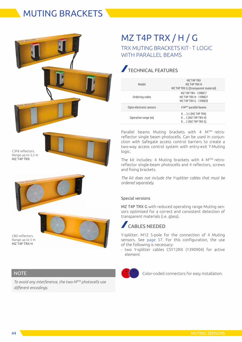
NOTE
To avoid any interference, the two MTRX photocells use different encodings.
MZ T4P TRX / H / GTRX MUTING BRACKETS KIT - T LOGIC WITH PARALLEL BEAMS
TECHNICAL FEATURES
ModelMZ T4P TRX
MZ T4P TRX H MZ T4P TRX G ((transparent material)
Ordering codesMZ T4P TRX - 1390817
MZ T4P TRX H - 1390827 MZ T4P TRX G - 1390820
Opto-electronic sensors 4 MTRX parallel beams
Operative range (m)0 ... 3,5 (MZ T4P TRX) 0 ... 5 (MZ T4P TRX H) 0 ... 2 (MZ T4P TRX G)
Parallel beams Muting brackets with 4 MTRX retro- reflector single beam photocells. Can be used in conjun-ction with Safegate access control barriers to create a two-way access control system with entry-exit T-Muting logic.
The kit includes: 4 Muting brackets with 4 MTRX retro- reflector single-beam photocells and 4 reflectors, screws and fixing brackets.
The kit does not include the Y-splitter cables that must be ordered separately.
Special versions
MZ T4P TRX G with reduced operating range Muting sen-sors optimised for a correct and consistent detection of transparent materials (i.e. glass).
CABLES NEEDED
Y-splitter: M12 5-pole for the connection of 4 Muting sensors. See page 57. For this configuration, the use of the following is necessary: - two Y-splitter cables CSY12RX (1390904) for active element
C8D reflectors. Range up to 5 m MZ T4P TRX H
C3F8 reflectors. Range up to 3,5 m MZ T4P TRX
Color-coded connectors for easy installation.

45MUTING SENSORS
MUTING BRACKETS
DIMENSIONS
Active element
Passiv element
360
18,5
25086
,57,
5250
Dimension: mm
360
37,52,5
11
70
Ø6
60 60
360
250 60
360
25060
Passive element
360
250 60
360
25060
C3F8 reflectors. Range up to 3,5 m MZ T4P TRX
C8D reflectors. Range up to 5 m MZ T4P TRX H

46
Dimensions: mm
MUTING SENSORS
M5
MULTI-BEAM PHOTOCELL
TECHNICAL FEATURES
Operative range (m) 0 ... 3,5 (0 ... 5 M5H models)
Measurement time (ms) < 100
Power supply (VDC) 24 ± 20%
Power comsumption at 24 VDC (W) 1
Number of beams 5
Beam spacing (mm) 10
Outputs on receiver 0 or 24V (PNP 100 mA 24 VDC) dark-on
Immunity to the ambient light (lx) > 10000 (solar)
Emission angle ± 5°
Emission wavelenght (nm) 940 (modulated infrared)
Electrical connectionsPigtail cable with M12 5-pole (emitter and receiver)
Fastening Back slot with L brackets
Dimension h x w x d (mm) 70 x 28 x 30
Cable length (mm) 900
PART NUMBERS
M5 (A coding): 1250910 M5H (A coding): 1250916 M5 (B coding): 1250911 M5H (B coding): 1250917
Note: The use of different coding is recommended for the installation of two M5 multi-beam photocells next to each other in order to avoid interference.
DIMENSIONS
Through-beam barrier type photocell with 5 beams.
Ideal for installation as Muting sensor, allows to detect also the most difficoult objects like, for exam-ple, piles of pallets.
With a compact metal housing and a polycarbonate protective front window, it offers the right degree of robustness ideal also in the most demanding envi-ronments.
The integrated status signaling lamp allows to easily verify the status of the system.
STATUS DISPLAY
LED State Description
EmitterON Beam emitted
OFF No beam
Receiver
ON Controlled area is free
ONBreak condition (controlled area is obstucted)
Blinking Fault detect
Protection rate: IP65
Operating temperature: -30 ... +55 °C
506
14
5
70
==
28
30
Backlit top cover with status LED

47MUTING SENSORS
Backlit top cover with status LED
MTRX
RETRO-REFLECTOR PHOTOCELL
TECHNICAL FEATURES
Operative range (m) It varies de-pending on the model of the reflector
Reflector M TRX M TRX G
C3F10 0 ... 2,5 0 ... 1,5
C3F8 0 ... 3,5 0 ... 2
CD8 0 ... 5 0 ... 3
Measurement time (ms) 65
Power supply (VDC) 24 ± 20%
Power coms. at 24 VDC (W) 0,2
Number of beams 1
Outputs 0 or 24 VDC (PNP 100 mA dark-on)
Emission angle ± 5°
Emission wavelenght (nm) 660 (modulated infrared)
Electrical connections Pigtail cable with M12 5-pole
Fastening Back slot with L bracket
Dimension h x w x d (mm) 70 x 28 x 30
Cable length (mm) 900
PART NUMBERS
MTRX (A coding): 1250912 MTRX G (A coding): 1250914 MTRX (B coding): 1250913 MTRX G (B coding): 1250915
NOTE: The use of different coding is recommended for the installation of two MTRX photocells next to each other in order to avoid interference.
Reflectors. See page 40
Single-beam retro-reflection photocell, consisting of:■ Active TX/RX■ Reflector (to be ordered separately)
With a compact metal housing and a polycarbonate protective front window, it offers the right degree of robustness ideal also in the most demanding envi-ronments.
Two models are available: MTRX and MTRX GLASS with low scanning range to optimise correct and consi-stent detection of transparent materials (i.e. glass).
The integrated status signaling lamp allows to easily verify the status of the system.
STATUS DISPLAY
LED State Description
Active element
ON Controlled area is free
ONBreak condition (controlled area is obstucted)
Blinking Fault detect
Protection rate: IP65
Operating temperature: -30 ... +55 °C
Dimension: mm
506
14 5
70
==
28
30
DIMENSIONS
1029

48 MUTING SENSORS
REFLECTOR
Ø 84
Ø 4,8
8
r 430
Reflector CD8
30
59 79
15
8
Ø 10
r 10
r 223
7,2
2
Mounting: with provided brackets Operative range (m): 0 ... 3,5
106
114
30
==
8Ø
3
45°
Reflector C3F10
Reflector C3F8
Mounting: with fixing screws (not provided) Operative range (m): 0 ... 5
Mounting: with fixing screws (not provided) Operative range (m): 0 ... 2,5
PART NUMBERS
Reflector CD8: 1210032
Reflector C3F8: 1210221
Reflector C3F10: 1210035
SFB 4M BRACKETS
BRAKETS FOR PHOTOCELLS M5 AND MTRX
Set of 4 swivel brackets for MZ SAFEGATE Muting sensor support. For correct fixing of the M5 and MTRX photocells on the SAFEGATE MZ support
PART NUMBER
SFB 4M brackets: 1250901

49ACCESSORIES
INTERFACES
AD SR0 and AD SR0A safety relay modules. Can be connected to Safegate safety light curtains or with any light curtain equipped with feedback input for monitoring external relays (EDM).
■ Guided-contact safety relays■ Additional NC contact line for the monitoring by
light curtain (EDM)
This product uses two guided con-tact safety relays manufactured by DOLD (type OA or OA 5643 5644) and certified by TUEV Rheinland.
AD SR0 - AD SR0ASAFETY RELAY MODULES FOR DEVICES WITH INTEGRATED FEEDBACK INPUT FOR EDM
TECHNICAL FEATURES
Safety relay outputs
AD SR0 2 NO + 1 NC - 2 A 250 VAC Each NO safety output line is inter-rupted twice by the two relays
AD SR0A 2 NO - 2 A 250 VAC
Response time (ms) ≤ 20
Power supply (VDC) 24 ± 20%
Electrical connections On terminal block
Operating temperature (°C) 0 ... +55
Protection ratingIP20 for housing IP2X for terminal block
FasteningDIN rail fastening according to EN 50022-35 standard
Dimensions h x w x d (mm) 101 x 35 x 120
PART NUMBERS
AD SR0 and AD SR0A module includes multi-language in-struction manual and CE declaration of conformity.
Ordering codes AD SR0: 1330902 AD SR0A: 1330903
E S P E
Certi�ed byTÜV Rheinland
Product Safety GmbH

50
M SG / M SGO BOXCONNECTION BOX FOR SAFEGATE SAFETY LIGHT CURTAINS
TECHNICAL FEATURES
ModelM SG BOX
M SGO BOX
M SG BOX RST
M SG BOX PLUS
M SGO BOX PLUS
M SG BOX
OSSD
M SGO BOX
OSSD
M SG BOX
RST P
Ordering code 1390953 1390952 1390959 1390955 1390556 1390957 1390958 1390960
Integrated Muting lamp
no yes no no yes no yes no
Safety outputRelay
2 NO + 1 NC * 2A - 250 VAC
Relay 4 NO + 1 NC * 2A - 250 VAC
OSSD 2 static PNP
400mA - 24VCC
Override yes no yes no
I/O modules connection
no yes
Start/Restart yes
Dimensions h x w x d (mm)
210 x 110 x 95
* Each NO safety output line is interrupted twice by the integrated relays.
CABLES NEEDED
Model Connectors Cables neededConnectable
models
M SG BOX M12 12-pole for receiver (active TRX element) connection
M12 5-pole for emitter connection
See page 55 (CFF12Px)
See page 54 (CFM5Px)
All excepted model S
M SG BOX PLUS
M SG BOX OSSD
M SGO BOX M12 12-pole for receiver (active TRX element) connection
M12 5-pole for emitter connection
M12 5-pole for Muting lamp connection
See page 55 (CFF12Px)
See page 54 (CFM5Px)
See page 54 (CFM5Px)
All excepted model S
M SGO BOX PLUS
M SGO BOX OSSD
M SG BOX RST
M12 8-pole for receiver (active TRX element) connection
M12 5-pole for emitter connection
See page 56 (CFF8Px)
See page 54 (CFM5Px)
Model S and S TRX only
M SG BOX RST P
M12 5-pole for active TRX-A element connection
M12 5-pole for profisafe I/O modules
See page 56 (CJBEx)
See page 54 (CFM5Px)
Model S TRX-A only
M SG and M SGO connection boxes are accessory devices designed for a quick and reliable connection of Safegate light curtains and to provide all major operating controls in the guarded area.■ Lighted button for Start/Restart function with
green LED indicating output status■ Key switch controlling the override function■ Pilot lamp indicating Muting function active
(M SGO BOX model only)■ Connection to the light curtain via connectors■ Dip switches for configuration of light curtain and
Muting functions■ 2 built-in safety relays with guided contacts
driven and controlled by the light curtain■ Internal terminal blocks for cable connections■ Electrical connection through cable gland:
- Power supply
- Connection to the internal relays output contacts and related EDM signal input
- External Muting enable and partial Muting signals
- Light curtains status signal
APPROVALS■ 2014/30/EU: “Electromagnetic Compatibility
Directive”■ UL (C+US) mark for USA and Canada
E S P E
M SG BOX
M SGO BOX
M SG BOX RST
ACCESSORIES
CONNECTION BOXES

51
Ø 14,5
M 12x1
461 - Brown
2 - White
3 - Blue
4 - Black
5 - Grey
2
3
54
1
Ø 13,8
M 12x1
1 - White
2 - Brown
3 - Green
4 - Yellow
5 - Grey
6 - Pink
7 - Blue
8 - Red
2
3
54
1
6
8
7
46
ACCESSORIES
CABLES
CD xM12 FEMALE STRAIGHT CONNECTOR 5-POLE
Model Code Description
CD 5 1330950 Pre-wired cable 5 m
CD 10 1330956 Pre-wired cable 10 m
CD 15 1330952 Pre-wired cable 15 m
CD 20 1330957 Pre-wired cable 20 m
CD 25 1330949 Pre-wired cable 25 m
CD 50 1330965 Pre-wired cable 50 m
Emitter connection.
C8D xM12 FEMALE STRAIGHT CONNECTOR 8-POLE
Model Code Description
C8D 5 1330980 Pre-wired cable 5 m
C8D 10 1330981 Pre-wired cable 10 m
C8D 15 1330982 Pre-wired cable 15 m
C8D 25 1330967 Pre-wired cable 25 m
C8D 40 1330966 Pre-wired cable 40 m
Models S receiver connection.
CJSxM12 MALE STRAIGHT CONNECTOR 5-POLE
Modello Codice Descrizione
CJS1 1390915 Pre-wired cable 1 m
CJS3 1390916 Pre-wired cable 3 m
External Muting lamp
External photocells connection
46
M 12x1
2
3 5
4
1
1 - Brown
2 - White
3 - Blue
4 - Black
5 - Gray

Ø 20
≈ 60
M 12x1
Ø 20
35
M 12x1
30,5
52
CDM 9M12 FEMALE STRAIGHT CONNECTOR 5-POLE SCREW TERMINAL, PG9 CABLE GLAND
Model Code
CDM 9 1330954
Emitter connection.
CDM 99M12 FEMALE 90° ANGLE CONNECTOR 5-POLE SCREW TERMINAL, PG9 CABLE GLAND
Model Code
CDM 99 1330955
Emitter connection.
C8DM 9M12 FEMALE STRAIGHT CONNECTOR 8-POLE SCREW TERMINAL, PG9 CABLE GLAND
Model Code
C8DM 9 1330986
Models S receiver connection.
C8DM 99M12 FEMALE 90° ANGLE CONNECTOR 8-POLE SCREW TERMINAL, PG9 CABLE GLAND
Model Code
C8DM 99 1330987
Models S receiver connection.
Ø 20
≈ 60
M 12x1
Ø 20
35
M 12x1
30,5
ACCESSORIES
CABLES
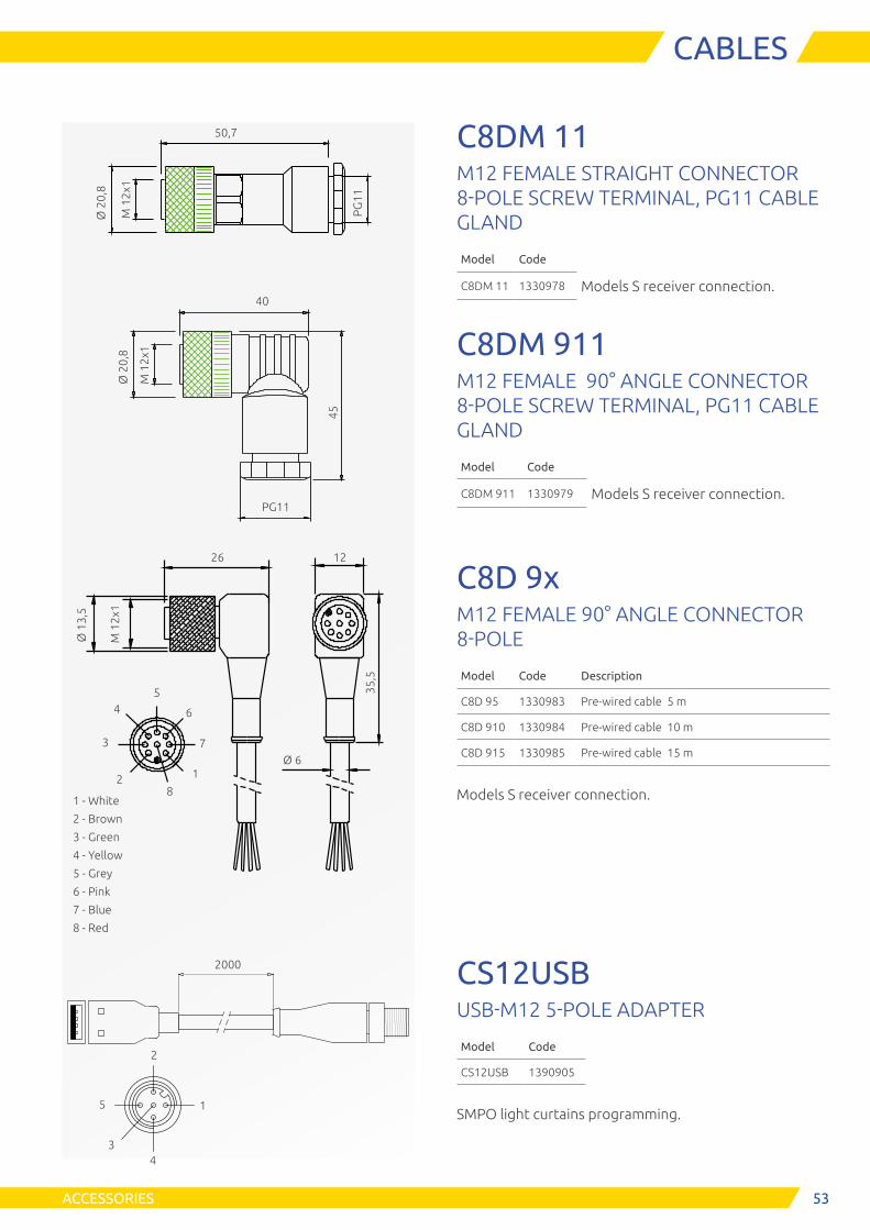
53ACCESSORIES
CABLESØ
13,
5
M 1
2x1
35,5
1 - White
2 - Brown
3 - Green
4 - Yellow
5 - Grey
6 - Pink
7 - Blue
8 - Red
2
3
54
1
6
8
7Ø 6
26 12
Ø 2
0,8
M 1
2x1
PG
11
50,7Ø
20,
8
40
M 1
2x1
45
PG11
C8DM 11M12 FEMALE STRAIGHT CONNECTOR 8-POLE SCREW TERMINAL, PG11 CABLE GLAND
Model Code
C8DM 11 1330978 Models S receiver connection.
C8DM 911M12 FEMALE 90° ANGLE CONNECTOR 8-POLE SCREW TERMINAL, PG11 CABLE GLAND
Model Code
C8DM 911 1330979 Models S receiver connection.
C8D 9xM12 FEMALE 90° ANGLE CONNECTOR 8-POLE
Model Code Description
C8D 95 1330983 Pre-wired cable 5 m
C8D 910 1330984 Pre-wired cable 10 m
C8D 915 1330985 Pre-wired cable 15 m
Models S receiver connection.
CS12USBUSB-M12 5-POLE ADAPTER
Model Code
CS12USB 1390905
SMPO light curtains programming.
2
1
3
5
4
2000

54 ACCESSORIES
CABLES
Ø 14,5
M 12x1
46
102
3
47
116
12
7
8
9
1
1 - Brown 2 - Blue 3 - White 4 - Green 5 - Pink 6 - Yellow 7 - Black 8 - Grey 9 - Red 10 - Violet 11 - Grey/Pink 12 - Red/Blue
5
CS12DxM12 FEMALE STRAIGHT CONNECTOR 12-POLE
Model Code Description
CS12D3 1390900 Pre-wired cable 3 m
CS12D5 1390901 Pre-wired cable 5 m
CS12D10 1390902 Pre-wired cable 10 m
CS12D15 1390906 Pre-wired cable 15 m
CS12D20 1390907 Pre-wired cable 20 m
Receiver connection.
CFM5PxCABLE WITH 2 M12 5-POLE MALE/ FEMALE STRAIGHT CONNECTORS
Model Code Description
CFM5P3 1390908 Pre-wired cable 3 m
CFM5P5 1390909 Pre-wired cable 5 m
CFM5P10 1390911 Pre-wired cable 10 m
Connection between:
Safegate emitter and boxes: M SG, M SGO, M SG PLUS, M SGO PLUS, M SG OSSD, M SGO OSSD.
Auxiliary Muting lamp connector and boxes: M SGO, M SGO PLUS, M SGO OSSD.
Profisafe I/O modules and box: M SG RST P.
Ø 14,5
M 12x1
46
2
3
54
1
46
2
3
54
1
1 - Brown
2 - White
3 - Blue
4 - Black
5 - Gray
1 - Brown
2 - White
3 - Blue
4 - Black
5 - Gray

55ACCESSORIES
CABLES
CFF12PxCABLE WITH 2 M12 12-POLE FEMALE STRAIGHT CONNECTORS
Model Code Description
CFF12P3 1390912 Pre-wired cable 3 m
CFF12P5 1390913 Pre-wired cable 5 m
CFF12P10 1390914 Pre-wired cable 10 m
Connection between Safegate reciver or active element (TRX model) main connector and boxes: M SG, M SGO, M SG PLUS, M SGO PLUS, M SG OSSD, M SGO OSSD.
Ø 14,5
M 12x1
46
102
3
47
116
12
7
8
9
1
5
Ø 14,5
M 12x1
46
102
3
47
116
12
7
8
9
1
5
1 - Brown 2 - Blue 3 - White 4 - Green 5 - Pink 6 - Yellow 7 - Black 8 - Grey 9 - Red 10 - Violet 11 - Grey/Pink 12 - Red/Blue
1 - Brown 2 - Blue 3 - White 4 - Green 5 - Pink 6 - Yellow 7 - Black 8 - Grey 9 - Red 10 - Violet 11 - Grey/Pink 12 - Red/Blue

56
Ø 14,5
M 12x1
4646
1 - White
2 - Brown
3 - Green
4 - Yellow
5 - Grey
6 - Pink
7 - Blue
8 - Red
2
3
54
1
6
8
7
2
3
54
1
6
8
7
Ø 14,5
M 12x1
4646
1 -Brown
2 - White
3 - Blue
4 - Black
5 - Grey
2
3
54
1
2
3
54
1
ACCESSORIES
CABLES
CFF8PxCABLE WITH 2 M12 8-POLE FEMALE STRAIGHT CONNECTORS
Model Code Description
CFF8P3 1390918 Pre-wired cable 3 m
CFF8P5 1390919 Pre-wired cable 5 m
CFF8P10 1390920 Pre-wired cable 10 m
Connection between Safegate reciver or active element (TRX model) main connector and boxes: M SG RST.
CJBExCABLE WITH 2 M12 5 POLE FEMALE STRAIGHT CONNECTORS
Model Code Description
CJBE3 1360960 Pre-wired cable 3 m
CJBE5 1360961 Pre-wired cable 5 m
CJBE10 1360962 Pre-wired cable 10 m
Connection between Safegate active element (TRX-A mo-del) main connector and boxes: M SG RST P.

3
15
2
4
3
15
2
4
200
mm
200
mm
3
1
5
24
5757ACCESSORIES
CABLES
CSY12RXM12 5-POLE Y-SPLITTER FOR THE CON-NECTION OF 4 MUTING SENSORS RECEIVER / ACTIVE ELEMENT (TRX)
Model Code
CSY12RX 1390904 TX
RX
24 V
24 V
24 V Sensor 1-2
24 V
24 V Sensor 1-2
24 V
Sync A
Sync A
0 VDC
Sync A
0 VDC
0 VDC
0 VDC
0 VDC0 VDC
0 VDC
PE
PE
PE
PE
PE
PE
M12 Male
M12 Female
M12 Female
M12 Female
M12 Female
M12 Male
Sensor 2
Sensor 1
Sensor 2
Sensor 1
CSY12TXM12 5-POLE Y-SPLITTER FOR THE CON-NECTION OF 4 MUTING SENSORS EMITTER
Model Code
CSY12TX 1390903
Y-splitter for Muting sensors.
TX
RX
24 V
24 V
24 V Sensor 1-2
24 V
24 V Sensor 1-2
24 V
Sync A
Sync A
0 VDC
Sync A
0 VDC
0 VDC
0 VDC
0 VDC0 VDC
0 VDC
PE
PE
PE
PE
PE
PE
M12 Male
M12 Female
M12 Female
M12 Female
M12 Female
M12 Male
Sensor 2
Sensor 1
Sensor 2
Sensor 1

58
FMC CB
FMC CBL
A: column height
B: column height with base FMC CB or FMC CBL
A
202
B
224
ACCESSORIES
COLUMNS
Support columns for Safegate safety light curtains, designed to provide secure fastening to the floor, fast installation, and a simple and precise adjustment of the optical alignment of the system.
Steel base with spring system for a perfect adjustment of the column vertical axis.
Made by aluminium extrusion poles, with adjustable angular orientation. Easy assembling and disassem-bling of the light curtain with easy adjustment of the first beam’s height.
Allow the installation of the MA Muting arms or MZ Muting brackets to the column itself.
FMC SG BR Models complete with PG11 rear union for light curtain cable sheath.
FMC SGFLOOR-MOUNTED SUPPORT COLUMNS
PART NUMBERS
Columns*
ModelFMC SGB2
FMC SGB3
FMC SGB4
FMC SG1700
FMC SG2000
Ordering codes 1200700 1200701 1200702 1200703 1200704
Model with PG11 rear union for cable sheath
FMC SGB2 R
FMC SGB3 R
FMC SGB4 R
FMC SG1700 R
FMC SG2000 R
Ordering codes 1200705 1200706 1200707 1200708 1200709
A - Height (mm) 1000 1200 1330 1670 1970
B - Overall height with FMC CB base (mm)
1055 1255 1385 1725 2025
B - Overall height with FMC CBL base (mm)
1037 1237 1367 1707 2007
For light curtains with: 2 beams 3 beams 4 beams
Controlled height up
to 1360 mm
Controlled height up
to 1660 mm
Bases for columns*
Model FMC CB FMC CBL
Ordering codes 1200500 1200501
Description Base for columnBase for column with
reduced height
Height (mm) 55 37
Steel foundation inserts included with the product.
*Note for ordering
Column ordering codes do not include the base which must be ordered separately (FMC CB and FMC CBL models).
MA Muting arms and
MZ Muting brackets can be mounted
directly to the column
Built-in spirit level for a correct posi-tioning of the vertical axis on the upper cover of the column.
PG11 rear union FMC EBR models

59ACCESSORIES
COLUMNS
FMC SG CAP-OUPPER COVER WITH CENTRAL HOLE FOR MUTING LAMPAn upper cover without spirit level is available as an accessory. The central hole allows the light curtain to move upwards making the Status / Muting lamp visible.
Ordering code: 1390954
NOTE: The upward movement of the light curtains must respect the standards. (distances and beams positioning).
Ø 6
,5 x
3
3
Ø 40
90
75,3
43,5
9,5
90
71
63,9
411
,5
30°
The following table shows the correct position of the light curtain (distance between the first beam and ground):
Column model H, distance between first beam and ground (mm)
FMC-SGB2 FMC-SGB2R
≤ 400 mm
FMC-SGB3 FMC-SGB3R FMC-SGB4 FMC-SGB4R FMC-SG1700 FMC-SG1700R FMC-SG2000 FMC-SG2000R
≤ 300 mm
POSITIONING OF THE LIGHT CURTAINS
MA Muting arms or MZ Muting brackets can be mounted directly to the column

60 ACCESSORIES
COLUMNS
FMC S / FMC SBCOLUMNS WITH DEFLECTING MIRRORS
PART NUMBERS
Model FMC S2 FMC S3 FMC S4 FMC S 1700 FMC S 2000
Ordering codes 1200620 1200621 1200622 1200625 1200623
Description
Single mirror for 2 beams and controlled
height up to 700 mm light curtains
Single mirror for 3 beams and controlled
height up to 900 mm light curtains
Single mirror for 4 beams and controlled
height up to 900 mm light curtains
Single mirror for controlled height up
to 1360 mm
Single mirror for controlled height up
to 1660 mm
A - Height (mm) 1000 1200 1330 1670 1970
B - Overall height with FMC
CB base (mm)1055 1255 1385 1725 2025
B - Overall height with FMC
CBL base (mm)1037 1237 1367 1707 2007
Model FMC SB2 FMC SB3 FMC SB4
Ordering codes 1200645 1200646 1200647
Description2 mirrors for 2 beams light
curtains
3 mirrors for 3 beams light
curtains
4 mirrors for 4 beams light
curtains
A - Height (mm) 1000 1200 1330
B - Overall height with FMC
CB base (mm)1055 1255 1385
B - Overall height with FMC
CBL base (mm)1037 1237 1367
Note for ordering
Column ordering codes do not include the base which must be ordered separately (FMC CB and FMC CBL models). See page 48 "Bases for columns"
Support columns with deflecting mirrors, designed to provide secure fastening to the floor, fast installation, and a simple and precise adjustment of the optical alignment of the system.
FMC S models with pre-assembled deflecting mirrors, allow perimeter protections of up to 4 sides.
FMC SB models with pre-installed independent adjustable deflecting mirrors for safety light grids with 2, 3 and 4 beams. For applications with multi-ple sides and/or with a large protected perimeter is recomended the use of this models.
Optical power reduction factor: 15% for each mirror.
Special models equipped with mirror with protective anti-fragmentation film available on request.
NOTE: for more information on how to chose mirrors, please refers to ReeR website, section “Light Curtains - Applications”.
FMC CB
FMC CBL
A: column height
B: column height with base FMC CB or FMC CBL
A
202
B22
4
FMC S
FMC SB
FMC CB

61ACCESSORIES
MIRRORS
The SP deflecting mirrors allow to create perimeter protection of areas with access points on multiple sides, with a considerable reduction of costs.
This solution eliminates the need to use more than one safety light curtain. Can be used to create perimeter protection of up to 4 sides.
SPDEFLECTING MIRRORS
TECHNICAL FEATURES
Material Extruded aluminium
Mirror pre-fitted with heights (mm) 250 ... 1900
Angular orientationAdjustable using supplied brackets
Optical power reduction factor 15% (for each mirror)
Protective anti-fragmentation film Available on request
PART NUMBERS
ModelOrdering
codesHeight
H in picture (mm)
For light curtains with protected
height (mm)For light
grids with:
SP 300 S 1201806 400 310
SP 400 S 1201801 540 460
SP 600 S 1201811 715 610 2 beams
SP 700 S 1201802 885 760
SP 900 S 1201812 1065 910 3 beams
SP 1100 S 1201803 1230 1060 4 beams
SP 1200 S 1201810 1400 1210
SP 1300 S 1201807 1450 1360
SP 1500 S 1201808 1600 1510
SP 1600 S 1201813 1750 1660
SP 1800 S 1201809 1900 1810
The following rules should be taken into consideration when using deflecting mirrors:
■ Total working distance (range) given by the sum of the lengths of all sides giving access to the protected area
■ Each mirror used will decrease the maximum working range between the Emitter and the Receiver by 15%
■ In order to ensure compliance mirrors must be placed at the minimum safety distance on each side from the danger zone
■ The use of the LAD laser alignement device is reco-mended for a quick and reliable alignment of the sys-tem expecially when using longer range light curtains or grids
NOTE: for more information on how to chose mirrors, please refers to ReeR website, section “Light Curtains - Applications”.
30H
30
33 33
1230
°
40
M8
110

62 ACCESSORIES
OTHERS
SFB SGADJUSTABLE BRACKETS
PARTS NUMBERS
Model Ordering codes Description
SFB 4SG 1390950Set of 4 adjustable brackets for protected heights up
to 1050 mm
SFB 6SG 1390951Set of 6 adjustable brackets for protected heights from
1200 mm
The SFB swivel brackets allow the rotation of the light curtain around its longitudinal axis, as well as the adjustment of its vertical and horizontal position.
The use of swivel brackets is recommended to align light curtains in long range applications or when deflecting mirrors are used and mild adjustment is necessary.
The test rod is an opaque cylinder to test the light curtain checking that no beams are bypassed due to the presence of reflecting surfaces.
The test is carried out by slowly moving the test rod (Ø = Resolution of the light curtain) in the centre and then along each side of the protected area. During this procedure the Green LED on the Receiver must always remain switched off.
TRTEST RODS
PART NUMBERS
Model Ordering codes Diameter
TR 30 1330962 ø 30 mm
TR 40 1330963 ø 40 mm

63
We put our Customers first
ReeR after sales service is committed to support all customers that need technical guidance regarding functionality, handling and installation of our products.
Customer Service Helpline +39 011 24 82 215
Monday to Friday 8.30 - 12.30 and 13.30-18.00 (CET)
or contact [email protected]
For product returns please visit www.reersafety.com for further information.
CUSTOMER SERVICE
ReeR SpA Via Carcano, 32 10153 Torino, Italy T +39 011 248 2215F +39 011 859 867
More than 60 years of quality and innovation
Founded in Turin (Italy) in 1959, ReeR distinguished itself for its strong commitment to innovation and technology.
A steady growth throughout the years allowed ReeR to become a point of reference in the safety automation industry at a worldwide level.
The Safety Division is in fact today a world leader in the development and manufacturing of safety optoelectronic sensors and controllers.
ReeR is ISO 9001, ISO 14001 and ISO 45001 certified.
Issue 2 - Rev. 1.4 March 2020
8946279 SAFEGATE - English
Printed in Italy
ReeR SpA does not guarantee that product information in this catalogue are the most current available.ReeR SpA reserves the right to make changes to the products described without notice and assumes no liability as a result of their use or application. Our goal is to keep the information on this catalogue timely and accurate, however ReeR SpA accepts no responsibility or liability whatsoever with regard to the information on this catalogue. Reproduction is not authorised, except with the expressed permission of ReeR SpA.
Made in Italysince 1959
www.reersafety.com | [email protected]