safety light curtains - air-oil · safety light curtains complies with osha, ansi, ... messages...
TRANSCRIPT

Safety Mat Systems
Safety Sensors and Controls for Industry
Safety Light Curtains
Complies with OSHA, ANSI,UL, and CE Standards P/N: 28-034
Customized sizes, shapes, and/orangles our specialty!
ErgonomicPalm Buttons
Quickview diagnostic displays forincreased productivity andmaximum operator safety!
The safest and only“control reliable” palm button that canbe used as a two-hand control device!
Air-O
il Sy
stems,
Inc.
www.a
iroil.co
m
© Pinnacle Systems, Inc. 2004 All Rights Reserved
Safety Light CurtainsMicroGuard Metal Box (Model MG) and DIN-rail (Model DR) ............................ A-1-A13MicroGuard Solid State (Model SS) ......................................................................... A-14-A-20PPG Series (Perimeter Guarding) ................................................................................ A21-A22
Safety Mat SystemsMat Comparison Chart ............................................................................................................. B1STTS (Soft Tactile Transducer System; completely monitored system) .................... B2-B15NSD (New Switching Device) .....................................................................................B16-B24
Ergonomic Palm ButtonsUltraTouch ...........................................................................................................................C1-C9
Safety Codes and Standards .....................................................................................D1
Domestic and International Standards’ Organizations ............D2-D4
Pinnacle Systems, Inc. reserves the right to make changes to the products and/ordocumentation without further notification.
Air-O
il Sy
stems,
Inc.
www.a
iroil.co
m

User friendly
Continual systemstatus checks
Easily viewedmessage display
Fits tight spaces
Highly reliable solidstate performance
Meets OSHA, UL,ANSI, CSA, RIA,and CE standards
DeviceNetTM
capable
Designed to meetinternationalstandards
DIN-rail and MetalBox Controllersavailable
Advanced control technologythin profile safety light curtain
A-1
Air-O
il Sy
stems,
Inc.
www.a
iroil.co
m
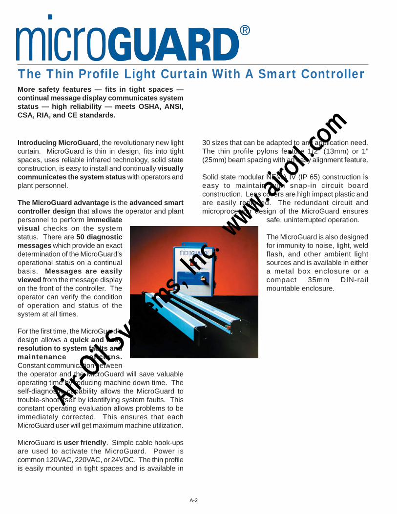
Introducing MicroGuard, the revolutionary new lightcurtain. MicroGuard is thin in design, fits into tightspaces, uses reliable infrared technology, solid stateconstruction, is easy to install and continually visuallycommunicates the system status with operators andplant personnel.
The MicroGuard advantage is the advanced smartcontroller design that allows the operator and plantpersonnel to perform immediatevisual checks on the systemstatus. There are 50 diagnosticmessages which provide an exactdetermination of the MicroGuard’soperational status on a continualbasis. Messages are easilyviewed from the message displayon the front of the controller. Theoperator can verify the conditionof operation and status of thesystem at all times.
For the first time, the MicroGuard’sdesign allows a quick and easyresolution to system faults andmaintenance concerns.Constant communication betweenthe operator and the MicroGuard will save valuableoperating time by reducing machine down time. Theself-diagnostic capability allows the MicroGuard totrouble-shoot itself by identifying system faults. Thisconstant operating evaluation allows problems to beimmediately corrected. This ensures that eachMicroGuard user will get maximum machine utilization.
MicroGuard is user friendly. Simple cable hook-upsare used to activate the MicroGuard. Power iscommon 120VAC, 220VAC, or 24VDC. The thin profileis easily mounted in tight spaces and is available in
30 sizes that can be adapted to any application need.The thin profile pylons feature 1/2” (13mm) or 1”(25mm) beam spacing with an easy alignment feature.
Solid state modular NEMA IV (IP 65) construction iseasy to maintain with snap-in circuit boardconstruction. Lens covers are high impact plastic andare easily replaced. The redundant circuit andmicroprocessor design of the MicroGuard ensures
safe, uninterrupted operation.
The MicroGuard is also designedfor immunity to noise, light, weldflash, and other ambient lightsources and is available in eithera metal box enclosure or acompact 35mm DIN-railmountable enclosure.
The Thin Profile Light Curtain With A Smart ControllerMore safety features — fits in tight spaces —continual message display communicates systemstatus — high reliability — meets OSHA, ANSI,CSA, RIA, and CE standards.
A-2
Air-O
il Sy
stems,
Inc.
www.a
iroil.co
m
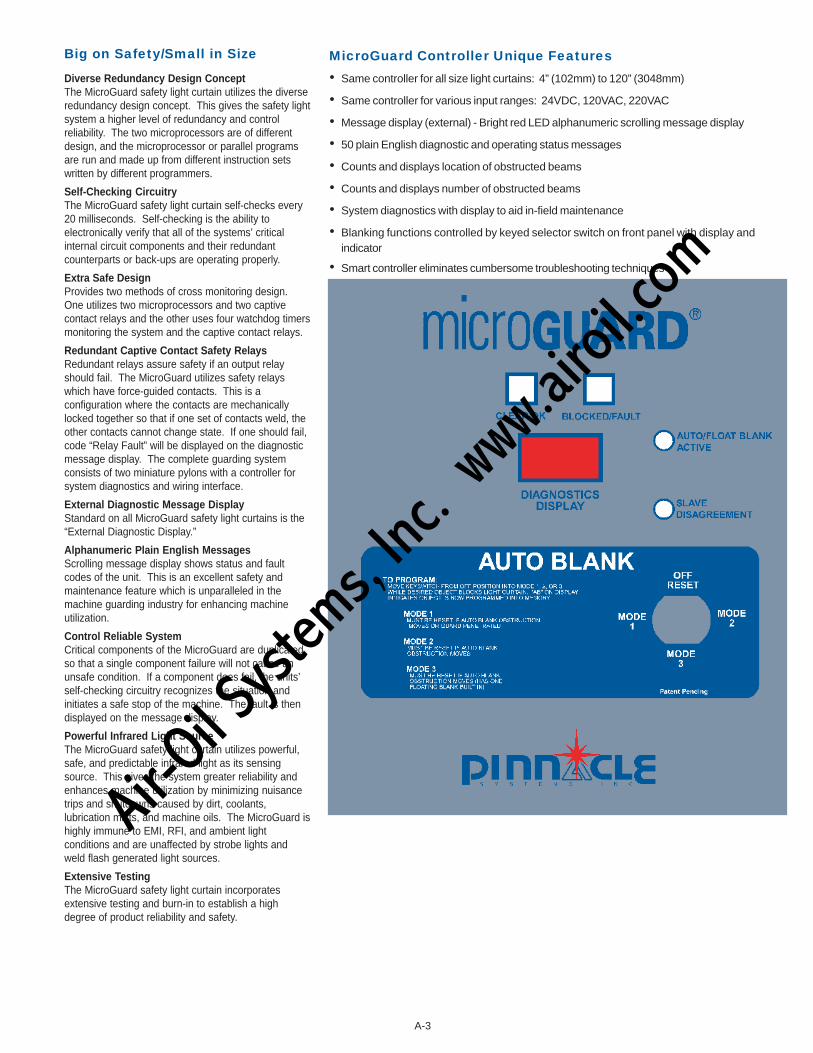
MicroGuard Controller Unique Features• Same controller for all size light curtains: 4” (102mm) to 120” (3048mm)
• Same controller for various input ranges: 24VDC, 120VAC, 220VAC
• Message display (external) - Bright red LED alphanumeric scrolling message display
• 50 plain English diagnostic and operating status messages
• Counts and displays location of obstructed beams
• Counts and displays number of obstructed beams
• System diagnostics with display to aid in-field maintenance
• Blanking functions controlled by keyed selector switch on front panel with display andindicator
• Smart controller eliminates cumbersome troubleshooting techniques
Big on Safety/Small in Size
Diverse Redundancy Design ConceptThe MicroGuard safety light curtain utilizes the diverseredundancy design concept. This gives the safety lightsystem a higher level of redundancy and controlreliability. The two microprocessors are of differentdesign, and the microprocessor or parallel programsare run and made up from different instruction setswritten by different programmers.
Self-Checking CircuitryThe MicroGuard safety light curtain self-checks every20 milliseconds. Self-checking is the ability toelectronically verify that all of the systems’ criticalinternal circuit components and their redundantcounterparts or back-ups are operating properly.
Extra Safe DesignProvides two methods of cross monitoring design.One utilizes two microprocessors and two captivecontact relays and the other uses four watchdog timersmonitoring the system and the captive contact relays.
Redundant Captive Contact Safety RelaysRedundant relays assure safety if an output relayshould fail. The MicroGuard utilizes safety relayswhich have force-guided contacts. This is aconfiguration where the contacts are mechanicallylocked together so that if one set of contacts weld, theother contacts cannot change state. If one should fail,code “Relay Fault” will be displayed on the diagnosticmessage display. The complete guarding systemconsists of two miniature pylons with a controller forsystem diagnostics and wiring interface.
External Diagnostic Message DisplayStandard on all MicroGuard safety light curtains is the“External Diagnostic Display.”
Alphanumeric Plain English MessagesScrolling message display shows status and faultcodes of the unit. This is an excellent safety andmaintenance feature which is unparalleled in themachine guarding industry for enhancing machineutilization.
Control Reliable SystemCritical components of the MicroGuard are duplicatedso that a single component failure will not cause anunsafe condition. If a component does fail, the units’self-checking circuitry recognizes the situation andinitiates a safe stop of the machine. The fault is thendisplayed on the message display.
Powerful Infrared Light SourceThe MicroGuard safety light curtain utilizes powerful,safe, and predictable infrared light as its sensingsource. This gives the system greater reliability andenhances machine utilization by minimizing nuisancetrips and shutdowns caused by dirt, coolants,lubrication mists, and machine oils. The MicroGuard ishighly immune to EMI, RFI, and ambient lightconditions and are unaffected by strobe lights andweld flash generated light sources.
Extensive TestingThe MicroGuard safety light curtain incorporatesextensive testing and burn-in to establish a highdegree of product reliability and safety.
A-3
Air-O
il Sy
stems,
Inc.
www.a
iroil.co
m
MicroGuard Smart ControllerWith the “Quickview Diagnostic Message Display”
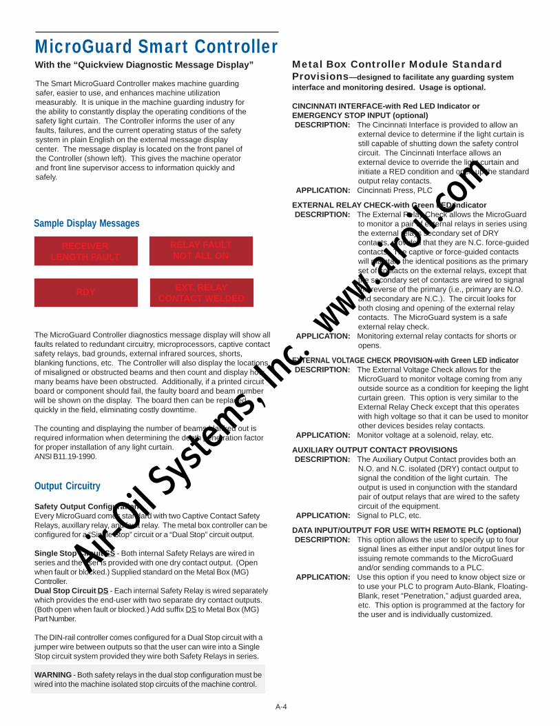
The Smart MicroGuard Controller makes machine guardingsafer, easier to use, and enhances machine utilizationmeasurably. It is unique in the machine guarding industry forthe ability to constantly display the operating conditions of thesafety light curtain. The Controller informs the user of anyfaults, failures, and the current operating status of the safetysystem in plain English on the external message displaycenter. The message display is located on the front panel ofthe Controller (shown left). This gives the machine operatorand front line supervisor access to information quickly andsafely.
Sample Display Messages
The MicroGuard Controller diagnostics message display will show allfaults related to redundant circuitry, microprocessors, captive contactsafety relays, bad grounds, external infrared sources, shorts,blanking functions, etc. The Controller will also display the locationsof misaligned or obstructed beams and then count and display howmany beams have been obstructed. Additionally, if a printed circuitboard or component should fail, the faulty board and beam numberwill be shown on the display. The board then can be replacedquickly in the field, eliminating costly downtime.
The counting and displaying the number of beams blanked out isrequired information when determining the depth penetration factorfor proper installation of any light curtain.ANSI B11.19-1990.
Output Circuitry
Safety Output ConfigurationEvery MicroGuard comes standard with two Captive Contact SafetyRelays, auxillary relay, and fault relay. The metal box controller can beconfigured for a “Single Stop” circuit or a “Dual Stop” circuit output.
Single Stop Circuit SS - Both internal Safety Relays are wired inseries and the user is provided with one dry contact output. (Openwhen fault or blocked.) Supplied standard on the Metal Box (MG)Controller.Dual Stop Circuit DS - Each internal Safety Relay is wired separatelywhich provides the end-user with two separate dry contact outputs.(Both open when fault or blocked.) Add suffix DS to Metal Box (MG)Part Number.
The DIN-rail controller comes configured for a Dual Stop circuit with ajumper wire between outputs so that the user can wire into a SingleStop circuit system provided they wire both Safety Relays in series.
WARNING - Both safety relays in the dual stop configuration must bewired into the machine isolated stop circuits of the machine control.
Metal Box Controller Module StandardProvisions—designed to facilitate any guarding systeminterface and monitoring desired. Usage is optional.
CINCINNATI INTERFACE-with Red LED Indicator orEMERGENCY STOP INPUT (optional)DESCRIPTION: The Cincinnati Interface is provided to allow an
external device to determine if the light curtain isstill capable of shutting down the safety controlcircuit. The Cincinnati Interface allows anexternal device to override the light curtain andinitiate a RED condition and open up the standardoutput relay contacts.
APPLICATION: Cincinnati Press, PLC
EXTERNAL RELAY CHECK-with Green LED IndicatorDESCRIPTION: The External Relay Check allows the MicroGuard
to monitor a pair of external relays in series usingthe external relays secondary set of DRYcontacts, provided that they are N.C. force-guidedcontacts. The captive or force-guided contactswill maintain the identical positions as the primaryset of contacts on the external relays, except thatthe secondary set of contacts are wired to signalthe reverse of the primary (i.e., primary are N.O.and secondary are N.C.). The circuit looks forboth closing and opening of the external relaycontacts. The MicroGuard system is a safeexternal relay check.
APPLICATION: Monitoring external relay contacts for shorts oropens.
EXTERNAL VOLTAGE CHECK PROVISION-with Green LED indicatorDESCRIPTION: The External Voltage Check allows for the
MicroGuard to monitor voltage coming from anyoutside source as a condition for keeping the lightcurtain green. This option is very similar to theExternal Relay Check except that this operateswith high voltage so that it can be used to monitorother devices besides relay contacts.
APPLICATION: Monitor voltage at a solenoid, relay, etc.
AUXILIARY OUTPUT CONTACT PROVISIONSDESCRIPTION: The Auxiliary Output Contact provides both an
N.O. and N.C. isolated (DRY) contact output tosignal the condition of the light curtain. Theoutput is used in conjunction with the standardpair of output relays that are wired to the safetycircuit of the equipment.
APPLICATION: Signal to PLC, etc.
DATA INPUT/OUTPUT FOR USE WITH REMOTE PLC (optional)DESCRIPTION: This option allows the user to specify up to four
signal lines as either input and/or output lines forissuing remote commands to the MicroGuardand/or sending commands to a PLC.
APPLICATION: Use this option if you need to know object size orto use your PLC to program Auto-Blank, Floating-Blank, reset “Penetration,” adjust guarded area,etc. This option is programmed at the factory forthe user and is individually customized.
RECEIVERLENGTH FAULT
RDY
RELAY FAULTNOT ALL ON
EXT. RELAYCONTACT WELDED
A-4
Air-O
il Sy
stems,
Inc.
www.a
iroil.co
m
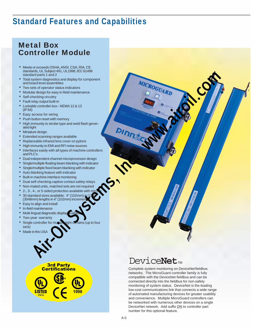
Standard Features and Capabilities
• Meets or exceeds OSHA, ANSI, CSA, RIA, CEstandards, UL Subject 491, UL1998, IEC 61496standard parts 1 and 2
• Total system diagnostics and display for componentand board level assemblies
• Two sets of operator status indicators• Modular design for easy in-field maintenance• Self-checking circuitry• Fault relay output built-in• Lockable controller box - NEMA 12 & 13
(IP 64)• Easy access for wiring• Push button reset with memory• High immunity to strobe type and weld flash gener-
ated light• Miniature design• Extended scanning ranges available• Replaceable infrared lens cover on pylons• High immunity to EMI and RFI noise sources• Interfaces easily with all types of machine controllers
and PLC’s• Dual independent channel microprocessor design• Single/multiple floating beam blanking with indicator• Single/multiple fixed beam blanking with indicator• Auto blanking feature with indicator• Built-in machine interface monitoring• Dual self-checking captive contact safety relays• Non-mated units, matched sets are not required• 2-, 3-, 4-, or 5-sided protection available with mirrors• 30 standard sizes available: 4" (102mm) to 120"
(3048mm) lengths in 4" (102mm) increments• Easy to align and install• In-field maintenance• Multi-lingual diagnostic display available• Two-year warranty• Single controller for multiple light curtains (up to four
sets)• Made in the USA
Metal BoxController Module
Complete system monitoring on DeviceNet fieldbusnetworks. The MicroGuard controller family is fullycompatible with the DeviceNet fieldbus and can beconnected directly into the fieldbus for non-safetymonitoring of system status. DeviceNet is the leadinglow-cost communications link that connects a wide rangeof automated manufacturing devices for greater usabilityand convenience. Multiple MicroGuard controllers canbe networked with numerous other devices on a singleDeviceNet network. Add suffix DN to controller partnumber for this optional feature.
DeviceNetTM
A-5
Air-O
il Sy
stems,
Inc.
www.a
iroil.co
m
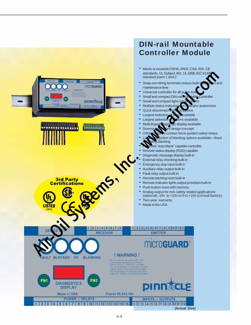
• Meets or exceeds OSHA, ANSI, CSA, RIA, CEstandards, UL Subject 491, UL1998, IEC 61496standard parts 1 and 2
• Snap-out wiring terminals reduce both installation andmaintenance time
• Universal controller for all pylon sizes• Small and compact DIN-rail Mountable Controller• Small and compact light curtain pylons• Multiple status indicators for operator awareness• Quick disconnect wiring at pylons• Largest selection of sizes available• Largest selection of options available• Multi-lingual diagnostic display available• Diverse redundant design concept• Utilizes captive contact force-guided safety relays• Largest selection of blanking options available—fixed
or floating blanking• Patented “auto blank” capable controller• Remote status display (RSD) capable• Diagnostic message display built-in• External relay checking built-in• Emergency stop input built-in• Auxiliary relay output built-in• Fault relay output built-in• Remote latching reset built-in• Remote indicator lights output provision built-in• Push button reset with memory• Analog output for non-safety related applications
(optional) -10v to +10v or 0 to +10v (consult factory)• Two-year warranty• Made in the USA
DIN-rail MountableController Module
(Actual Size)
A-6
Air-O
il Sy
stems,
Inc.
www.a
iroil.co
m

DIN-rail Remote Status Display (RSD)The optional Remote Status Display (RSD) may beused in conjunction with the MicroGuard DIN-railController. The RSD provides the machine operator andfront line supervisor immediate system status anddiagnostics when the DIN-rail Controller is mounted insidethe machine control panel. The RSD can also control allblanking options if that style light curtain is used.
Remote Status Display (RSD) Components:l Red/Green/Yellow indicator lightsl Diagnostic scrolling message display with 5' (1.5m) of
connector cablel Keyed selector switch and yellow blanking active
indicator supplied if blanking is used
The RSD components are mounted on a steel plate andare designed to be exterior panel mounted. The RSDoption enhances safety and is a time saver at machine set-up and when maintenance diagnostics are required.
(The RSD’s shown are actual size)
TM
Requires 3" (76mm) x 3" (76mm) Panel CutoutMounting Hole Dimensions 3.7" (94mm) x 3.7" (94mm) Center to Center
Requires 3" (76mm) x 5.10" (130mm) Panel Cutout — Mounting Hole Dimensions 3.7" (94mm) x 5.8" (147mm) Center to CenterA-7
KeyedSelectorSwitch
KeyedSelectorSwitch
Air-O
il Sy
stems,
Inc.
www.a
iroil.co
m
A-8
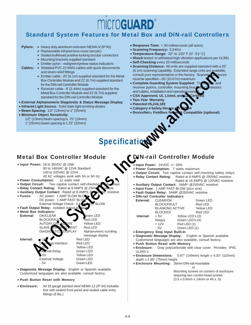
Pylons: • Heavy duty aluminum extrusion NEMA IV (IP 65)• Replaceable infrared lens cover (acrylic)• Sealed bulkhead positive locking circular connectors• Mounting brackets supplied standard• Emitter pylon - red/green/yellow status indicators
Cables: • Shielded PVC 22 AWG cables with quick disconnectsand strain relief fittings
• Emitter cable - 20' (6.1m) supplied standard for the MetalBox Controller Module and 22' (6.7m) supplied standardfor the DIN-rail Controller Module
• Receiver cable - 8' (2.44m) supplied standard for theMetal Box Controller Module and 22' (6.7m) suppliedstandard for the DIN-rail Controller Module
•External Alphanumeric Diagnostic & Status Message Display• Infrared Light Source: Solid state light emitting diodes•Beam Spacing: 1/2" (13mm) or 1" (25mm)•Minimum Object Sensitivity:
1/2" (13mm) beam spacing is .75" (19mm)1" (25mm) beam spacing is 1.25" (32mm)
Standard System Features for Metal Box and DIN-rail Controllers
•Response Time: < 30 milliseconds (all sizes)•Scanning Frequency: 5.9 Khz• Temperature Range: 32o to 120o F (0o -51o C)•Shock tested to withstand high vibration applications per UL991•Self-Checking every 20 milliseconds•Scanning Distance: All units are supplied standard with a 20'
(6.1m) scanning capability. Extended range units are available,consult your representative or the factory. Scanning distancesmust be specified—35' (10.67m) maximum.
•Complete Guarding System Supplied: Transmitter andreceiver pylons, controller, mounting brackets, connectorsand cables, installation and operation manual.
•CSA Approved, UL Listed, and CE Certified• Two-Year Warranty•Patented #5,243,183•Category 4 Safety Device per EN954•DeviceNetTM Fieldbus Network Compatible (optional)
Metal Box Controller Module• Input Power: 18 to 35VDC @ 10W
90 to 140VAC @ 12VA Standard140 to 220VAC @ 12VAAll AC voltages work with 50 or 60 Hz
• Power Consumption: 11 watts total• Output Circuit: Two captive contact self-checking safety relays• Relay Contact Rating: Rated at 8 AMPS @ 250VAC resistive• Auxiliary Output Contact: Rated at 8 AMPS @ 250VAC resistive• Fuses: AC power: 1 AMP SLOW BLOW
DC power: 1 AMP FAST BLOWExternal Voltage Check: 5 AMP FAST BLOW
• Fault Output Relay: Isolated output for faults• Metal Box Indicators:
External: OK/CLEAR Green LEDBLOCK/FAULT Red LEDAUTO/FLOAT ACTIVE Yellow LEDSLAVE DISAGREEMENT Red LEDDIAGNOSTICS DISPLAY Alphanumeric scrolling
message displayInternal: + 12V Red LED
Cincinnati Interface Red LED+ 5V Yellow LEDExternal Relay Green LED+ 5V Yellow LEDExternal Voltage Green LED- 5V Green LED
• Diagnostic Message Display: English or Spanish available.Customized languages are also available, consult factory.
• Push Button Reset with Memory
• Enclosure: All 18 gauge painted steel NEMA 12 (IP 64) lockablebox with sealed front panel and sealed cable entryfittings (8 lbs.)
• Input Power: 24VDC +/- 20%• Power Consumption: 7 watts maximum• Output Circuit: Two captive contact self-checking safety relays• Relay Contact Rating: Rated at 8 AMPS @ 250VAC resistive
Rated at 16 AMPS @ 120VAC resistive• Auxiliary Output Contact: 5AMP @250VAC resistive• Input Fuse: 1 AMP FAST BLOW (pico size)• Fault Output Relay: 5AMP @250VAC resistive• DIN-rail Controller Indicators
External: CLEAR/OK Green LEDBLOCK/FAULT Red LEDBLANKING ACTIVE Yellow LEDBLOCKED Red LED
Internal: + 5V Yellow LED’s (2)Relays Green LED’s (4)+ 12V Red LED (1)- 5V Green LED (1)
• Emergency Stop Input Built-In• Diagnostic Message Display: English or Spanish available.
Customized languages are also available, consult factory.• Push Button Reset with Memory• Enclosure: Gray polycarbonate with clear cover. Provides IP40,
UL94V-1• Enclosure Dimensions: 5.87" (149mm) length x 4.33" (110mm)
depth x 2.95" (75mm) height• Enclosure Mounting: 35mm DIN-rail mountable
orMounting screws on corners of enclosurerequiring two combo-head screws(3.5 x 0.6mm x 14mm or #6 x .5)
DIN-rail Controller Module
Specifications
Air-O
il Sy
stems,
Inc.
www.a
iroil.co
m
A-9
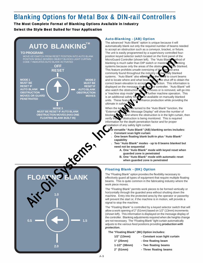
Blanking Options for Metal Box & DIN-rail ControllersTTTTThe Most Complete Fhe Most Complete Fhe Most Complete Fhe Most Complete Fhe Most Complete Fororororormamamamamat oft oft oft oft of Blanking Options Blanking Options Blanking Options Blanking Options Blanking Options AAAAAvvvvvailaailaailaailaailabbbbble in Industrle in Industrle in Industrle in Industrle in IndustryyyyySelect the Style Best Suited fSelect the Style Best Suited fSelect the Style Best Suited fSelect the Style Best Suited fSelect the Style Best Suited for or or or or YYYYYour our our our our AAAAApplicapplicapplicapplicapplicationtiontiontiontion
Auto-Blanking - (AB) OptionThe advanced “Auto Blank” option is unique because it willautomatically blank out only the required number of beams neededto accept an obstruction such as a conveyor, bracket, or fixture.The unit is easily programmed by a supervisory controlled four-position keyed selector switch located on the front panel of theMicroGuard Controller (shown left). The “Auto Blank” method ofblanking is much safer than DIP switch or master/slave blankingsystems because only the areas of the obstruction will be blanked.This feature prohibits unsafe oversizing of the blanked areacommonly found throughout the industry on manually blankedsystems. “Auto Blank” also eliminates the need to count beamsand to locate where and what beams are to be shut off to obtain thecorrect beam elevation to accept an obstruction. This information isdisplayed on the message display of the controller. “Auto Blank” willalso watch the obstruction and, if it moves or is removed, will go intoa “machine stop mode” to prevent further machine operation. Thisis an additional safety feature not available on manually blankedunits. These features truly enhance production while providing theultimate in safety.
When the key switch is turned to the “Auto Blank” function, the“External Diagnostic Message Display” will show the number ofblocked beams and where the obstruction is in the light curtain, thenverify that the obstruction is being monitored. This is requiredinformation for the depth penetration factor and for properinstallation of any safety light curtain.
The versatile “Auto Blank” (AB) blanking series includes:l Constant scan light curtainl One beam floating blank built-in plus “Auto Blank”
capabilityl Two “Auto Blank” modes - up to 8 beams blanked but
need not be sequentialA. One “Auto Blank” mode with keyed reset when
guarded zone is penetratedB. One “Auto Blank” mode with automatic reset
when guarded zone is penetrated
Floating Blank - (8K) OptionThe “Floating Blank” option provides the flexibility necessary toeffectively guard all types of equipment that require multiple floatingbeams. This is quite common in the fabricating industry where thework piece moves.
The “Floating Blank” permits work pieces to be formed vertically orhorizontally through the guarded area without shutting down themachine. Entry into the protected area by the operator or passerbywill prevent the start or, if the machine is in motion, will provide asignal to stop the machine.
The “Floating Blank” is controlled by a keyed selector switch that willallow a work opening of 2" (51mm) based on 1/2" (13mm) increments(shown left). This information is displayed on the message display ofthe controller. Blanking adjustments required when die heights changeare not necessary. The “Floating Blank” light curtain automaticallyadjusts to the various feed positions providing production withprotection.
The “Floating Blank” (8K) Option includes:
1/2" (13mm) - Constant scan light curtain
1" (25mm) - One floating beam
1-1/2" (38mm) - Two floating beams
2" (51mm) - Three floating beams
FLOATING BLANK
0.5
2.0
1.0
1.5
TO PROGRAM:MOVE KEYSWITCH FROM RESET POSITION INTO AUTO BLANKPOSITION WHILE DESIRED OBJECT BLOCKS LIGHT CURTAINCODE 7 INDICATES AUTO BLANK ACTIVATED
AUTO BLANKINGT M
MODE 1MUST BERESET IFAUTO BLANKOBSTRUCTIONMOVES OR GUARDPENETRATED
MODE 3MUST BE RESET IF AUTO BLANKOBSTRUCTION MOVES (HAS ONE
FLOATING BLANK BUILT IN)
MODE 2MUST BERESET IF
AUTO BLANKOBSTRUCTION
MOVES
OFFRESET
Air-O
il Sy
stems,
Inc.
www.a
iroil.co
m
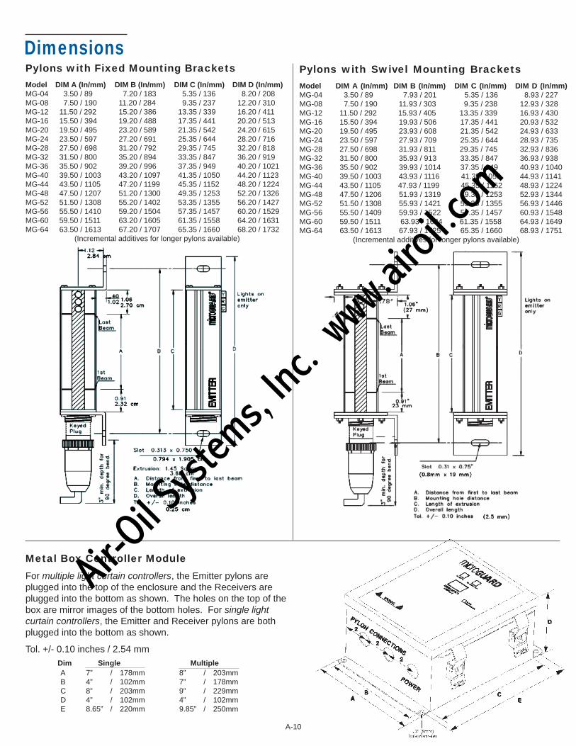
Pylons with Fixed Mounting BracketsModel DIM A (In/mm) DIM B (In/mm) DIM C (In/mm) DIM D (In/mm)MG-04 3.50 / 89 7.20 / 183 5.35 / 136 8.20 / 208MG-08 7.50 / 190 11.20 / 284 9.35 / 237 12.20 / 310MG-12 11.50 / 292 15.20 / 386 13.35 / 339 16.20 / 411MG-16 15.50 / 394 19.20 / 488 17.35 / 441 20.20 / 513MG-20 19.50 / 495 23.20 / 589 21.35 / 542 24.20 / 615MG-24 23.50 / 597 27.20 / 691 25.35 / 644 28.20 / 716MG-28 27.50 / 698 31.20 / 792 29.35 / 745 32.20 / 818MG-32 31.50 / 800 35.20 / 894 33.35 / 847 36.20 / 919MG-36 35.50 / 902 39.20 / 996 37.35 / 949 40.20 / 1021MG-40 39.50 / 1003 43.20 / 1097 41.35 / 1050 44.20 / 1123MG-44 43.50 / 1105 47.20 / 1199 45.35 / 1152 48.20 / 1224MG-48 47.50 / 1207 51.20 / 1300 49.35 / 1253 52.20 / 1326MG-52 51.50 / 1308 55.20 / 1402 53.35 / 1355 56.20 / 1427MG-56 55.50 / 1410 59.20 / 1504 57.35 / 1457 60.20 / 1529MG-60 59.50 / 1511 63.20 / 1605 61.35 / 1558 64.20 / 1631MG-64 63.50 / 1613 67.20 / 1707 65.35 / 1660 68.20 / 1732
(Incremental additives for longer pylons available)
Dimensions
Metal Box Controller ModuleFor multiple light curtain controllers, the Emitter pylons areplugged into the top of the enclosure and the Receivers areplugged into the bottom as shown. The holes on the top of thebox are mirror images of the bottom holes. For single lightcurtain controllers, the Emitter and Receiver pylons are bothplugged into the bottom as shown.
Tol. +/- 0.10 inches / 2.54 mmDim Single MultipleA 7” / 178mm 8” / 203mmB 4” / 102mm 7” / 178mmC 8” / 203mm 9” / 229mmD 4” / 102mm 4” / 102mmE 8.65” / 220mm 9.85” / 250mm
A-10
Pylons with Swivel Mounting BracketsModel DIM A (In/mm) DIM B (In/mm) DIM C (In/mm) DIM D (In/mm)MG-04 3.50 / 89 7.93 / 201 5.35 / 136 8.93 / 227MG-08 7.50 / 190 11.93 / 303 9.35 / 238 12.93 / 328MG-12 11.50 / 292 15.93 / 405 13.35 / 339 16.93 / 430MG-16 15.50 / 394 19.93 / 506 17.35 / 441 20.93 / 532MG-20 19.50 / 495 23.93 / 608 21.35 / 542 24.93 / 633MG-24 23.50 / 597 27.93 / 709 25.35 / 644 28.93 / 735MG-28 27.50 / 698 31.93 / 811 29.35 / 745 32.93 / 836MG-32 31.50 / 800 35.93 / 913 33.35 / 847 36.93 / 938MG-36 35.50 / 902 39.93 / 1014 37.35 / 949 40.93 / 1040MG-40 39.50 / 1003 43.93 / 1116 41.35/ 1050 44.93 / 1141MG-44 43.50 / 1105 47.93 / 1199 45.35 / 1152 48.93 / 1224MG-48 47.50 / 1206 51.93 / 1319 49.35 / 1253 52.93 / 1344MG-52 51.50 / 1308 55.93 / 1421 53.35 / 1355 56.93 / 1446MG-56 55.50 / 1409 59.93 / 1522 57.35 / 1457 60.93 / 1548MG-60 59.50 / 1511 63.93 / 1624 61.35 / 1558 64.93 / 1649MG-64 63.50 / 1613 67.93 / 1725 65.35 / 1660 68.93 / 1751 (Incremental additives for longer pylons available)
Air-O
il Sy
stems,
Inc.
www.a
iroil.co
m

Cornering Mirror DimensionsThrough the use of cornering mirrors, multiple sides orwork envelopes can be guarded which enhance safetyand down-time related to mechanical and electricalinterlock systems. Be sure to include a 5% reflectivity lossper mirror when calculating total scanning distance of lightcurtain.
Note: Mirrors are surface coated.
AccessoriesPedestal Dimensions (Model 8000)The heavy duty, all-welded steel pedestal floor mounts canbe used for mounting either the emitter pylons, receiverpylons, and/or cornering mirrors. Sliding mounts on thepedestal are universal in design and are supplied standard.Unique floating base on pedestal is designed tocompensate for uneven floors.
Note: Pedestals must be bolted to the floor afterinstallation; they must not be movable.
1) Sliding mounts supplied2) Standard height = 72" (1829mm) Model 8000
Optional 96" (2438mm), Model 80963) Painted OSHA yellow4) Pedestal - 12 gauge steel
Base Plate - .25" (6mm) steel plateOrdering Procedure: Specify PedestalModel # and Quantity
DIM A (in/ mm) DIM B (in/mm) DIM C (in/mm)MODEL (hole to hole) (mirror length) (total length)
MGM-04 7.45 / 189 6.25 / 159 8.50 / 216MGM-08 11.45 / 291 10.25 / 260 12.50 / 318MGM-12 15.45 / 392 14.25 / 362 16.50 / 419MGM-16 19.45 / 494 18.25 / 464 20.50 / 521MGM-20 23.45 / 596 22.25 / 565 24.50 / 622MGM-24 27.45 / 697 26.25 / 667 28.50 / 724MGM-28 31.45 / 799 30.25 / 768 32.50 / 826MGM-32 35.45 / 900 34.25 / 870 36.50 / 927MGM-36 39.45 / 1002 38.25 / 972 40.50 / 1029MGM-40 43.45 / 1104 42.25 / 1073 44.50 / 1130MGM-44 47.45 / 1205 46.25 / 1175 48.50 / 1232MGM-48 51.45 / 1307 50.25 / 1276 52.50 / 1334MGM-52 55.45 / 1408 54.25 / 1378 56.50 / 1435MGM-56 59.45 / 1510 58.25 / 1480 60.50 / 1537MGM-60 63.45 / 1612 62.25 / 1581 64.50 / 1638MGM-64 67.45 / 1713 66.25 / 1683 68.50 / 1740
Swing Mount Brackets (Model 9000)Excellent method of mounting the light guard for pressbrakes or when the light guard is to be moved for diesetups or machine maintenance. Model 9000 consists ofthree, 180° - pivot points along with light guard diagonalmovement capability for virtually unlimited light guardpositioning. Two-inch square tubing 3/16” (5mm) thickpainted OSHA yellow which mounts directly onto themachine housing and makes for a heavy duty yet versatilemounting bracket.
Ordering Procedure: Specify Pedestal Model # andQuantity.
• Specify Model 9000 Swing Mount Brackets andquantity.
• Specify B & C dimensions required.• Specify light curtain or mirror size to be mounted.
A-11
Air-O
il Sy
stems,
Inc.
www.a
iroil.co
m

A-12
Ordering Procedure
Light Curtain Controller Module HousingMG - NEMA 12 & 13 (IP 64) stand alone Metal Box Controller ModuleDR - 35mm DIN-rail Mountable Controller Module (24VDC Input Power Only)
Pylon Sizes (Protected Area in inches)1/2" (13mm) Beam Spacing: 04,08,12,16,20,24,28,32,36,40,44,48,52,56,60,64
1" (25mm) Beam Spacing: 04,08,12,16,20,24,28,32,36,40,44,48,52,56,60,64,68,72,76,80,84,88,92,96,100,104,108,112,116,120
Light Curtain Style and Beam Spacing
1/2" (13mm) Spacing of BeamsOF - Constant scan - no blanking.1F - 1 beam floating blank built-in.8K - Up to 3 beam floating blank adjustable by the use of a keyswitch removable in all positions. Capable
of constant scan or one, two, or three floating beams.AB - Includes constant scan light curtain, one beam floating blank, and two auto blank modes.CE - No blanking, 24VDC input power, 2° angle of divergence, and CE certified (designed to conform to the
European Market and worldwide IEC 61496 Parts 1 & 2 Standards).
1" ( 25mm) Spacing of BeamsOF1 - Constant scan - no blanking.1F1 - 1 beam floating blank built-in.8K1 - Up to 3 beam floating blank adjustable by the use of a keyswitch removable in all positions. Capable
of constant scan or one, two, or three floating beams.AB1 - Includes constant scan light curtain, one beam floating blank, and two auto blank modes.CE1 - No blanking, 24VDC input power, 2° angle of divergence, and CE certified (designed to conform to the
European Market and worldwide IEC 61496 Parts 1 & 2 Standards).
Options (Add underlined suffix to part number)
AVAILABLE ON BOTH METAL BOX & DIN-RAIL CONTROLLERS
SMB - Swivel Mounting Brackets for Pylons: Replaces the fixed mounting brackets normally supplied.Provides a 360o rotation of pylons.
MO - Guarding Mute-Out: Mutes out the light curtain during the non-hazardous portion of the machine cycle.DN - DeviceNetTM: Fieldbus network compatible.
Extended Range Units: 21' (6.4m) to 35' (10.67m) scanning distances (specify desired scanning distance).
AVAILABLE ON THE METAL BOX CONTROLLER
DS - Dual Individual Stop Outputs, description on page A-4LR - Resettable Latching Relays: Requires the light curtain to be manually reset every time the sensing
field is penetrated (built-in standard on the DIN-rail Controller Module).SC - Single Controller for Multiple Light Curtains: Cost effective approach when a machine requires
multiple light curtains. All curtains are controlled by a single MicroGuard controller. Up to four sets ofpylons can be connected to the controller.
ES - Emergency Stop Input: E-Stop input requiring the MicroGuard to issue a stop command (built-in standardon the DIN-rail Controller Module).
24VDC - 24VDC Input Power: Required for 24VDC input power.220VAC - 220VAC Input Power: Required for 220VAC input power.
AVAILABLE ON THE DIN-RAIL CONTROLLER
RSD - DIN-rail Remote Status Display (RSD): Remote mounting plate providing a single location to mountthe following on existing panel door: light curtain scrolling diagnostic message display, blanking optionkeyswitch (if applicable), and status indicator lights (all styles).
CI - Cincinnati Interface: Requires the MicroGuard to issue a stop command every machine cycle (built-in standardon the Metal Box Controller Module).
AO - Analog Output for Non-Safety Applications: -10VDC to +10VDC or 0VDC to +10VDC.
Light CurtainController ModuleHousing
PylonSize
Scanning distancein feet–20' (6.1m)standard, 35'(10.67m) maximum
Light CurtainStyle andBeam Spacing
MG - 04 - OF - 20 - (Options)ExamplePart #
Air-O
il Sy
stems,
Inc.
www.a
iroil.co
m

A-13
Formula for calculating lightcurtain safety distance
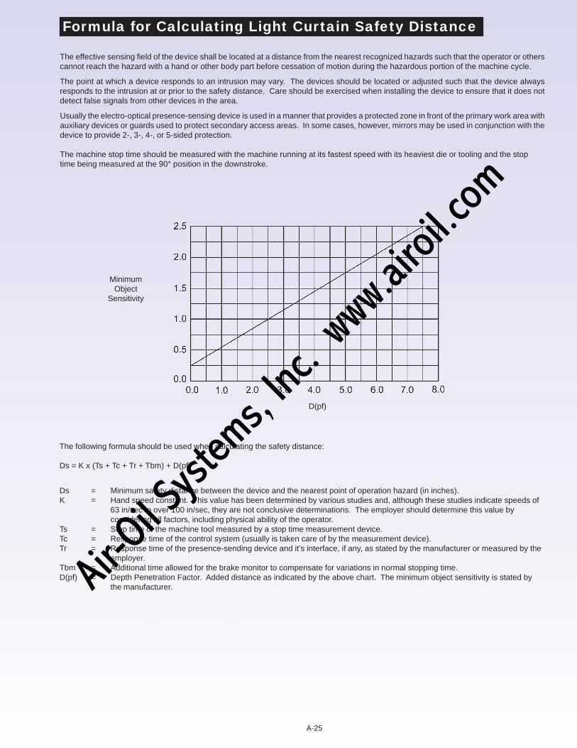
The effective sensing field of the device shall be located at a distance from the nearest recognized hazards such that the operator or otherscannot reach the hazard with a hand or other body part before cessation of motion during the hazardous portion of the machine cycle.
The point at which a device responds to an intrusion may vary. The devices should be located or adjusted such that the device alwaysresponds to the intrusion at or prior to the safety distance. Care should be exercised when installing the device to ensure that it does notdetect false signals from other devices in the area.
Usually the electro-optical presence-sensing device is used in a manner that provides a protected zone in front of the primary work area withauxiliary devices or guards used to protect secondary access areas. In some cases, however, mirrors may be used in conjunction with thedevice to provide 2-, 3-, 4-, or 5-sided protection.
The machine stop time should be measured with the machine running at its fastest speed with its heaviest die or tooling and the stop timebeing measured at the 90° position in the downstroke.
The following formula should be used when calculating the safety distance:
Ds = K x (Ts + Tc + Tr + Tbm) + D(pf)
Ds = Minimum safety distance between the device and the nearest point of operation hazard (in inches).K = Hand speed constant. This value has been determined by various studies and, although these studies indicate speeds of 63
in/sec to over 100 in/sec, they are not conclusive determinations. The employer should determine this value by considering allfactors, including physical ability of the operator.
Ts = Stop time of the machine tool measured by a stop time measurement device.Tc = Response time of the control system (usually is taken care of by the measurement device).Tr = Response time of the presence-sending device and it’s interface, if any, as stated by the manufacturer or measured by the
employer.Tbm = Additional time allowed for the brake monitor to compensate for variations in normal stopping time.D(pf) = Depth Penetration Factor. Added distance as indicated by the above chart. The minimum object sensitivity is stated by the
manufacturer.
MinimumObject
Sensitivity
D(pf)
EXTRA PYLON PROTECTION (OPTIONAL)
PT - Polycarbonate tube which will encase the pylons for high impact protection.
AT - Acrylic Tube which will encase the pylons for protection from caustic and/or chemical agents.
Air-O
il Sy
stems,
Inc.
www.a
iroil.co
m

MicroGuardModel SSSafety Light Curtainwith Solid State Outputs
®
Low Cost Solutionfor OEM’s/Integrators
Compact “Control Reliable”Category 4 Design
The Easiest IntelligentBlanking Setup Available
No Dip Switches orPylon Entry Required for Blanking
System Designed toEliminate Time ConsumingLockout/Tagout Proceduresfor Blanking Adjustments
Total System Diagnostics
Made in USA
A-14
Air-O
il Sy
stems,
Inc.
www.a
iroil.co
m
2
Model SS -- The Ultimate in Safety – Quality – Value
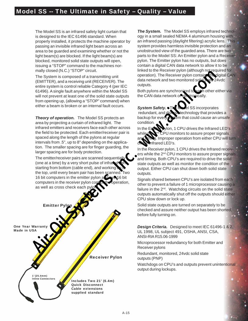
The Model SS is an infrared safety light curtain thatis designed to the IEC 61496 standard. Whenproperly installed, it protects the machine operator bypassing an invisible infrared light beam across anarea to be guarded and examining whether or not thelight beam(s) are blocked. If the light beam(s) areblocked, monitored solid state outputs will open,issuing a “STOP” command to the machines nor-mally closed (N.C.) “STOP” circuit.
The System is composed of a transmitting unit(EMITTER), and a receiving unit (RECEIVER). Theentire system is control reliable Category 4 (per IEC61496). A single fault anywhere within the Model SSwill not prevent at least one of the solid state outputsfrom opening up, (allowing a “STOP” command) wheneither a beam is broken or an internal fault occurs.
Theory of operation. The Model SS protects anarea by projecting a curtain of infrared light. Theinfrared emitters and receivers face each other acrossthe field to be protected. Each emitter/receiver pair isspaced along the length of the pylons at regularintervals from .5", up to 8" depending on the applica-tion. The smaller spacing are for finger guarding, thelarger spacing are for body protection.
The emitter/receiver pairs are scanned sequentially(one at a time) by a very short pulse of infrared lightstarting from bottom (cable end), and working up tothe top, until every beam pair has been scanned. Two16 bit computers in the emitter pylon and two 16 bitcomputers in the receiver pylon control the operation,as well as cross check each pylon.
The System. The Model SS employs infrared technol-ogy in a small sealed NEMA 4 aluminum housing withan infrared passing (daylight filtering) acrylic lens. Thissystem provides harmless invisible protection and anunobstructed view of the guarded area. There are twoparts to the Model SS: An Emitter pylon and a Receiverpylon. The Emitter pylon has no outputs, but doescontain a digital CAN data network to allow it to belinked to the Receiver pylon (although not required foroperation). The Receiver pylon contains the digital CANdata network and two monitored solid state 24vdcoutputs.
Both pylons are synchronized to each other either viathe CAN data network or electronically.
System Safety. The Model SS incorporates redundant, and diverse technology that provides abackup for every system that could cause an unsafecondition.
In the Emitter pylon, 1 CPU drives the Infrared LED’swhile the 2nd CPU monitors to assure proper signalsand timing. Improper operation from either CPU will turnoff the Infrared LED’s.
In the Receiver pylon, 1 CPU drives the Infrared receiv-ers while the 2nd CPU monitors to assure proper signalsand timing. Both CPU’s are required to drive the solidstate outputs as well as monitor the condition of theoutput. Either CPU can shut down both solid stateoutputs.
Signals shared between CPU’s are isolated from eachother to prevent a failure of 1 microprocessor causing afailure in the 2nd. Watchdog circuits on the solid stateoutputs automatically shut off the outputs should eitherCPU slow down or lock up.
Solid state outputs are turned on separately to bechecked and assure neither output has been shorted,before fully turning on.
Design Criteria. Designed to meet IEC 61496-1 & 2,UL 1998, UL subject 491, OSHA, ANSI, CSA,ANSI-RIA R15.06-1999
Microprocessor redundancy for both Emitter andReceiver pylons
Redundant, monitored, 24vdc solid stateoutputs (PNP)
Watchdogs on CPU’s and outputs prevent unintentionaloutput during lockups.
Emitter Pylon
Receiver Pylon
Includes Two 21’ (6.4m)Quick DisconnectCable extensionssupplied standard
One Year WarrantyMade in USA
1’ (25.4mm)Inline Connectors
A-15
Air-O
il Sy
stems,
Inc.
www.a
iroil.co
m
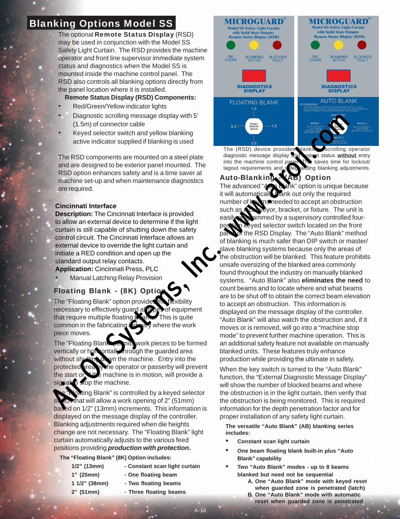
Blanking Options Model SSThe optional Remote Status Display (RSD)may be used in conjunction with the Model SSSafety Light Curtain. The RSD provides the machineoperator and front line supervisor immediate systemstatus and diagnostics when the Model SS ismounted inside the machine control panel. TheRSD also controls all blanking options directly fromthe panel location where it is installed.
Remote Status Display (RSD) Components:• Red/Green/Yellow indicator lights• Diagnostic scrolling message display with 5’
(1.5m) of connector cable• Keyed selector switch and yellow blanking
active indicator supplied if blanking is used
The RSD components are mounted on a steel plateand are designed to be exterior panel mounted. TheRSD option enhances safety and is a time saver atmachine set-up and when maintenance diagnosticsare required.
Floating Blank - (8K) OptionThe “Floating Blank” option provides the flexibilitynecessary to effectively guard all types of equipmentthat require multiple floating beams. This is quitecommon in the fabricating industry where the workpiece moves.
The “Floating Blank” permits work pieces to be formedvertically or horizontally through the guarded areawithout shutting down the machine. Entry into theprotected area by the operator or passerby will preventthe start or, if the machine is in motion, will provide asignal to stop the machine.
The “Floating Blank” is controlled by a keyed selectorswitch that will allow a work opening of 2” (51mm)based on 1/2” (13mm) increments. This information isdisplayed on the message display of the controller.Blanking adjustments required when die heightschange are not necessary. The “Floating Blank” lightcurtain automatically adjusts to the various feedpositions providing production with protection.
The “Floating Blank” (8K) Option includes:
1/2” (13mm) - Constant scan light curtain
1” (25mm) - One floating beam
1 1/2” (38mm) - Two floating beams
2” (51mm) - Three floating beams
The (RSD) device provides blanking scrolling operatordiagnostic message display and system status without entryinto the machine control panel. This saves time for lockout/tagout requirements and safeguarding blanking adjustments.
Cincinnati InterfaceDescription: The Cincinnati Interface is providedto allow an external device to determine if the lightcurtain is still capable of shutting down the safetycontrol circuit. The Cincinnati Interface allows anexternal device to override the light curtain andinitiate a RED condition and open up thestandard output relay contacts.Application: Cincinnati Press, PLC• Manual Latching Relay Provision
Auto-Blanking - (AB) OptionThe advanced “Auto Blank” option is unique becauseit will automatically blank out only the requirednumber of beams needed to accept an obstructionsuch as a conveyor, bracket, or fixture. The unit iseasily programmed by a supervisory controlled four-position keyed selector switch located on the frontpanel of the RSD Display. The “Auto Blank” methodof blanking is much safer than DIP switch or master/slave blanking systems because only the areas ofthe obstruction will be blanked. This feature prohibitsunsafe oversizing of the blanked area commonlyfound throughout the industry on manually blankedsystems. “Auto Blank” also eliminates the need tocount beams and to locate where and what beamsare to be shut off to obtain the correct beam elevationto accept an obstruction. This information isdisplayed on the message display of the controller.“Auto Blank” will also watch the obstruction and, if itmoves or is removed, will go into a “machine stopmode” to prevent further machine operation. This isan additional safety feature not available on manuallyblanked units. These features truly enhanceproduction while providing the ultimate in safety.
When the key switch is turned to the “Auto Blank”function, the “External Diagnostic Message Display”will show the number of blocked beams and wherethe obstruction is in the light curtain, then verify thatthe obstruction is being monitored. This is requiredinformation for the depth penetration factor and forproper installation of any safety light curtain.
The versatile “Auto Blank” (AB) blanking seriesincludes:
• Constant scan light curtain
• One beam floating blank built-in plus “AutoBlank” capability
• Two “Auto Blank” modes - up to 8 beamsblanked but need not be sequential
A. One “Auto Blank” mode with keyed resetwhen guarded zone is penetrated (latch)
B. One “Auto Blank” mode with automaticreset when guarded zone is penetrated
A-16
Air-O
il Sy
stems,
Inc.
www.a
iroil.co
m

4
· Base device to IEC 60204-1 and EN 954-1 for single-channel and two- channel emergency stop monitoring.· Category 4 to EN954-1· Stop category 0 to EN 60204-1· Manual or automatic start· With/without cross monitoring· Feedback circuit for monitoring external contactors· 3 enabling current paths, NO contacts, positively driven safety relays· For processing signals from the output signal switching devices (OSSD) of a light curtain acc. to DIN EN 61496-1· Input Power - 24VDC· Rated Frequency - 50-60 Hz· Outputs Rated Voltage - DC 22V Rated· Output Current - 100 MA
Part # SSSR
Converts the solid state PNPOutputs to force guided safetyrelay outputs (dry)
Mod
el S
S
Mod
el S
S
Mod
el S
S
Mod
el S
S
Mod
el S
S
Mod
el S
S
Mod
el S
S
Mod
el S
S
Mod
el S
S
Mod
el S
S
Mod
el S
S
Mod
el S
S
Mod
el S
S
Mod
el S
S
Mod
el S
S
Mod
el S
S
Model SSA Size to Meet Allof Your Guarding Needs
4”(102mm)
64”(1626mm)
Model SS Safety Relay Interface
A-17
Air-O
il Sy
stems,
Inc.
www.a
iroil.co
m
5
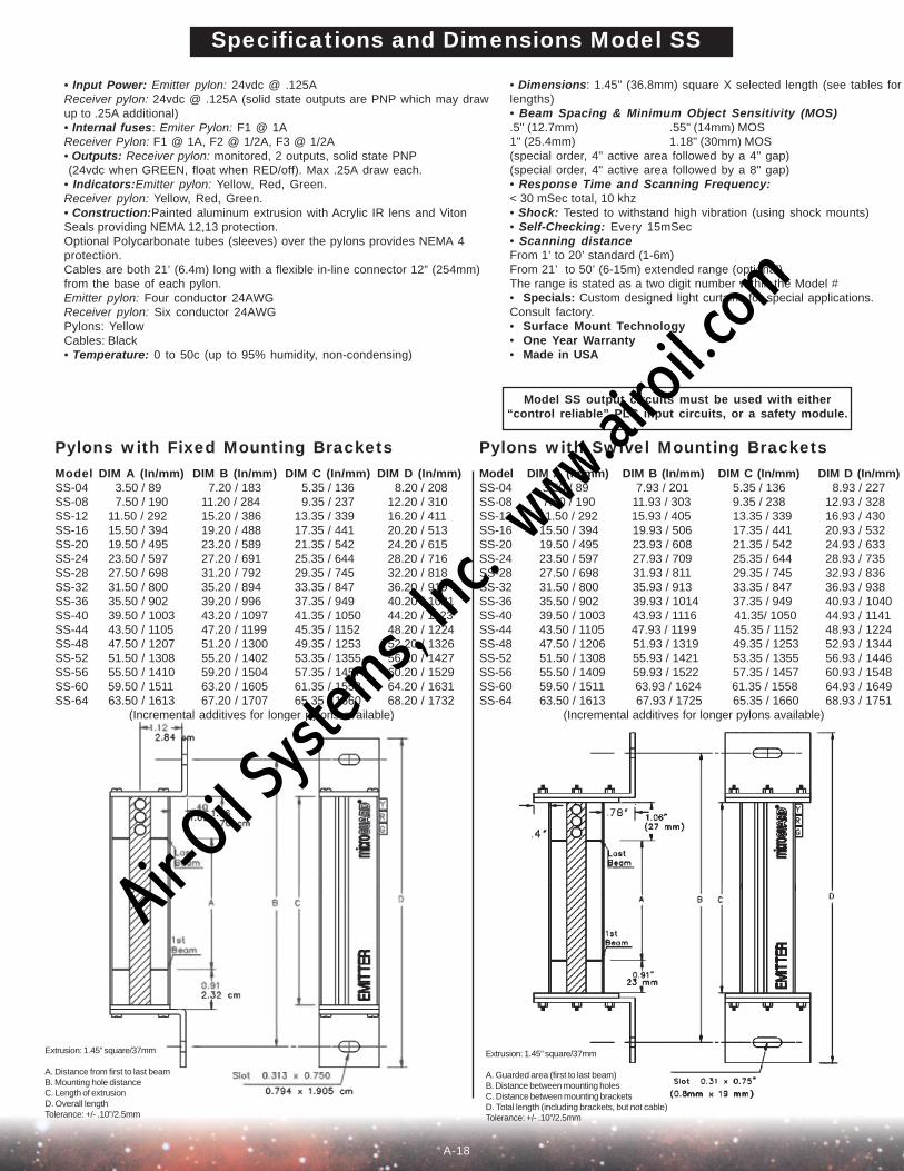
• Dimensions: 1.45" (36.8mm) square X selected length (see tables forlengths)• Beam Spacing & Minimum Object Sensitivity (MOS).5" (12.7mm) .55" (14mm) MOS1" (25.4mm) 1.18" (30mm) MOS(special order, 4" active area followed by a 4" gap)(special order, 4" active area followed by a 8" gap)• Response Time and Scanning Frequency:< 30 mSec total, 10 khz• Shock: Tested to withstand high vibration (using shock mounts)• Self-Checking: Every 15mSec• Scanning distanceFrom 1’ to 20’ standard (1-6m)From 21’ to 50’ (6-15m) extended range (optional)The range is stated as a two digit number within the Model #• Specials: Custom designed light curtains for special applications.Consult factory.• Surface Mount Technology• One Year Warranty• Made in USA
• Input Power: Emitter pylon: 24vdc @ .125AReceiver pylon: 24vdc @ .125A (solid state outputs are PNP which may drawup to .25A additional)• Internal fuses: Emiter Pylon: F1 @ 1AReceiver Pylon: F1 @ 1A, F2 @ 1/2A, F3 @ 1/2A• Outputs: Receiver pylon: monitored, 2 outputs, solid state PNP (24vdc when GREEN, float when RED/off). Max .25A draw each.• Indicators:Emitter pylon: Yellow, Red, Green.Receiver pylon: Yellow, Red, Green.• Construction:Painted aluminum extrusion with Acrylic IR lens and VitonSeals providing NEMA 12,13 protection.Optional Polycarbonate tubes (sleeves) over the pylons provides NEMA 4protection.Cables are both 21’ (6.4m) long with a flexible in-line connector 12” (254mm)from the base of each pylon.Emitter pylon: Four conductor 24AWGReceiver pylon: Six conductor 24AWGPylons: YellowCables: Black• Temperature: 0 to 50c (up to 95% humidity, non-condensing)
Specifications and Dimensions Model SS
Model SS output circuits must be used with either“control reliable” PLC input circuits, or a safety module.
Pylons with Swivel Mounting BracketsModel DIM A (In/mm) DIM B (In/mm) DIM C (In/mm) DIM D (In/mm)SS-04 3.50 / 89 7.93 / 201 5.35 / 136 8.93 / 227SS-08 7.50 / 190 11.93 / 303 9.35 / 238 12.93 / 328SS-12 11.50 / 292 15.93 / 405 13.35 / 339 16.93 / 430SS-16 15.50 / 394 19.93 / 506 17.35 / 441 20.93 / 532SS-20 19.50 / 495 23.93 / 608 21.35 / 542 24.93 / 633SS-24 23.50 / 597 27.93 / 709 25.35 / 644 28.93 / 735SS-28 27.50 / 698 31.93 / 811 29.35 / 745 32.93 / 836SS-32 31.50 / 800 35.93 / 913 33.35 / 847 36.93 / 938SS-36 35.50 / 902 39.93 / 1014 37.35 / 949 40.93 / 1040SS-40 39.50 / 1003 43.93 / 1116 41.35/ 1050 44.93 / 1141SS-44 43.50 / 1105 47.93 / 1199 45.35 / 1152 48.93 / 1224SS-48 47.50 / 1206 51.93 / 1319 49.35 / 1253 52.93 / 1344SS-52 51.50 / 1308 55.93 / 1421 53.35 / 1355 56.93 / 1446SS-56 55.50 / 1409 59.93 / 1522 57.35 / 1457 60.93 / 1548SS-60 59.50 / 1511 63.93 / 1624 61.35 / 1558 64.93 / 1649SS-64 63.50 / 1613 67.93 / 1725 65.35 / 1660 68.93 / 1751 (Incremental additives for longer pylons available)
Pylons with Fixed Mounting BracketsModel DIM A (In/mm) DIM B (In/mm) DIM C (In/mm) DIM D (In/mm)SS-04 3.50 / 89 7.20 / 183 5.35 / 136 8.20 / 208SS-08 7.50 / 190 11.20 / 284 9.35 / 237 12.20 / 310SS-12 11.50 / 292 15.20 / 386 13.35 / 339 16.20 / 411SS-16 15.50 / 394 19.20 / 488 17.35 / 441 20.20 / 513SS-20 19.50 / 495 23.20 / 589 21.35 / 542 24.20 / 615SS-24 23.50 / 597 27.20 / 691 25.35 / 644 28.20 / 716SS-28 27.50 / 698 31.20 / 792 29.35 / 745 32.20 / 818SS-32 31.50 / 800 35.20 / 894 33.35 / 847 36.20 / 919SS-36 35.50 / 902 39.20 / 996 37.35 / 949 40.20 / 1021SS-40 39.50 / 1003 43.20 / 1097 41.35 / 1050 44.20 / 1123SS-44 43.50 / 1105 47.20 / 1199 45.35 / 1152 48.20 / 1224SS-48 47.50 / 1207 51.20 / 1300 49.35 / 1253 52.20 / 1326SS-52 51.50 / 1308 55.20 / 1402 53.35 / 1355 56.20 / 1427SS-56 55.50 / 1410 59.20 / 1504 57.35 / 1457 60.20 / 1529SS-60 59.50 / 1511 63.20 / 1605 61.35 / 1558 64.20 / 1631SS-64 63.50 / 1613 67.20 / 1707 65.35 / 1660 68.20 / 1732
(Incremental additives for longer pylons available)
Extrusion: 1.45” square/37mm
A. Distance from first to last beamB. Mounting hole distanceC. Length of extrusionD. Overall lengthTolerance: +/- .10”/2.5mm
Extrusion: 1.45” square/37mm
A. Guarded area (first to last beam)B. Distance between mounting holesC. Distance between mounting bracketsD. Total length (including brackets, but not cable)Tolerance: +/- .10”/2.5mm
A-18
Air-O
il Sy
stems,
Inc.
www.a
iroil.co
m
6
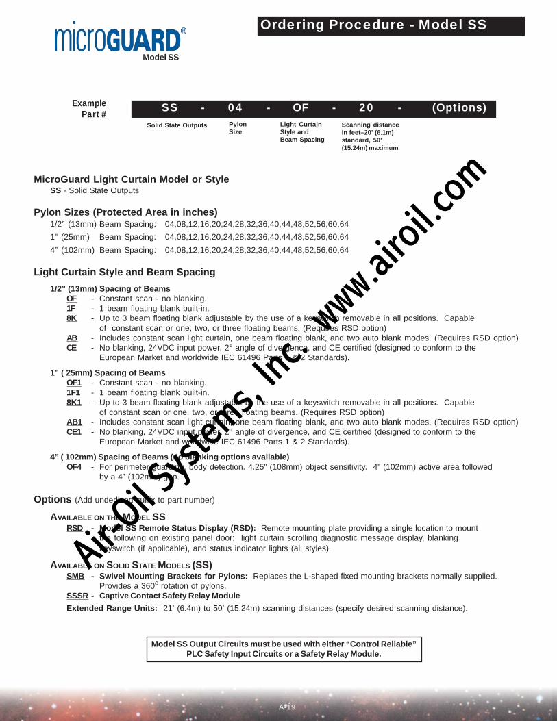
Ordering Procedure - Model SS
MicroGuard Light Curtain Model or StyleSS - Solid State Outputs
Pylon Sizes (Protected Area in inches)1/2” (13mm) Beam Spacing: 04,08,12,16,20,24,28,32,36,40,44,48,52,56,60,64
1” (25mm) Beam Spacing: 04,08,12,16,20,24,28,32,36,40,44,48,52,56,60,64
4” (102mm) Beam Spacing: 04,08,12,16,20,24,28,32,36,40,44,48,52,56,60,64
Light Curtain Style and Beam Spacing
1/2” (13mm) Spacing of BeamsOF - Constant scan - no blanking.1F - 1 beam floating blank built-in.8K - Up to 3 beam floating blank adjustable by the use of a keyswitch removable in all positions. Capable
of constant scan or one, two, or three floating beams. (Requires RSD option)AB - Includes constant scan light curtain, one beam floating blank, and two auto blank modes. (Requires RSD option)CE - No blanking, 24VDC input power, 2° angle of divergence, and CE certified (designed to conform to the
European Market and worldwide IEC 61496 Parts 1 & 2 Standards).
1” ( 25mm) Spacing of BeamsOF1 - Constant scan - no blanking.1F1 - 1 beam floating blank built-in.8K1 - Up to 3 beam floating blank adjustable by the use of a keyswitch removable in all positions. Capable
of constant scan or one, two, or three floating beams. (Requires RSD option)AB1 - Includes constant scan light curtain, one beam floating blank, and two auto blank modes. (Requires RSD option)CE1 - No blanking, 24VDC input power, 2° angle of divergence, and CE certified (designed to conform to the
European Market and worldwide IEC 61496 Parts 1 & 2 Standards).
4” ( 102mm) Spacing of Beams (no blanking options available)OF4 - For perimeter guarding, body detection. 4.25” (108mm) object sensitivity. 4” (102mm) active area followed
by a 4” (102mm) gap.
Options (Add underlined suffix to part number)
AVAILABLE ON THE MODEL SSRSD - Model SS Remote Status Display (RSD): Remote mounting plate providing a single location to mount
the following on existing panel door: light curtain scrolling diagnostic message display, blankingkeyswitch (if applicable), and status indicator lights (all styles).
AVAILABLE ON SOLID STATE MODELS (SS)SMB - Swivel Mounting Brackets for Pylons: Replaces the L-shaped fixed mounting brackets normally supplied.
Provides a 360o rotation of pylons.SSSR - Captive Contact Safety Relay Module
Extended Range Units: 21’ (6.4m) to 50’ (15.24m) scanning distances (specify desired scanning distance).
Solid State Outputs PylonSize
Scanning distancein feet–20’ (6.1m)standard, 50’(15.24m) maximum
Light CurtainStyle andBeam Spacing
SS - 04 - OF - 20 - (Options)ExamplePart #
Model SS
Model SS Output Circuits must be used with either “Control Reliable”PLC Safety Input Circuits or a Safety Relay Module.
A-19
Air-O
il Sy
stems,
Inc.
www.a
iroil.co
m
7
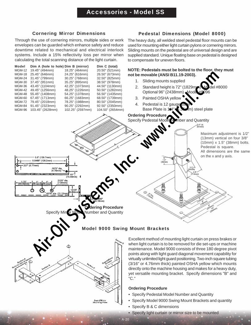
Cornering Mirror Dimensions Pedestal Dimensions (Model 8000)Through the use of cornering mirrors, multiple sides or workenvelopes can be guarded which enhance safety and reducedowntime related to mechanical and electrical interlocksystems. Include a 15% reflectivity loss per mirror whencalculating the total scanning distance of the light curtain.
Model Dim A (hole to hole) Dim B (mirror) Dim C (total)MGM-12 19.45" (494mm) 18.25" (464mm) 20.50" (521mm)MGM-18 25.45" (646mm) 24.25" (616mm) 26.50" (673mm)MGM-24 31.45" (799mm) 30.25" (768mm) 32.50" (825mm)MGM-30 37.45" (951mm) 35.25" (895mm) 38.50" (978mm)MGM-36 43.45" (1104mm) 42.25" (1073mm) 44.50" (1130mm)MGM-42 49.45" (1256mm) 48.25" (1226mm) 50.50" (1282mm)MGM-48 55.45" (1408mm) 54.25" (1378mm) 56.50" (1435mm)MGM-60 67.45" (1713mm) 66.25" (1683mm) 68.50" (1739mm)MGM-72 79.45" (2018mm) 78.25" (1988mm) 80.50" (2045mm)MGM-84 91.45” (2323mm) 90.25” (2292mm) 92.50” (2350mm)MGM-96 103.45” (2628mm) 102.25” (2597mm) 104.50” (2654mm)
Ordering ProcedureSpecify Mirror Model Number and Quantity
Model 9000 Swing Mount Brackets
Excellent method of mounting light curtain on press brakes orwhen light curtain is to be removed for die set-ups or machinemaintenance. Model 9000 consists of three 180 degree pivotpoints along with light guard diagonal movement capability forvirtually unlimited light guard positioning. Two-inch square tubing(3/16" or 4.76mm thick) painted OSHA yellow which mountsdirectly onto the machine housing and makes for a heavy duty,yet versatile mounting bracket. Specify dimensions "B" and"C."
Ordering Procedure
• Specify Pedestal Model Number and Quantity
• Specify Model 9000 Swing Mount Brackets and quantity
• Specify B & C dimensions
• Specify light curtain or mirror size to be mounted
Accessories - Model SS
Maximum adjustment is 1/2”(13mm) vertical on four 3/8”(10mm) x 1.5” (38mm) bolts.Pedestal is square.All dimensions are the sameon the x and y axis.
The heavy duty, all welded steel pedestal floor mounts can beused for mounting either light curtain pylons or cornering mirrors.Sliding mounts on the pedestal are of universal design and aresupplied standard. Unique floating base on pedestal is designedto compensate for uneven floors.
NOTE: Pedestals must be bolted to the floor, they mustnot be movable (ANSI B11.19-2003).
1. Sliding mounts supplied
2. Standard height is 72" (1829mm) - Model #8000Optional 96" (2438mm) - Model #8096
3. Painted OSHA yellow
4. Pedestal is 12 gauge steelBase Plate is 1/4" (6.35mm) steel plate
Ordering ProcedureSpecify Pedestal Model Number and Quantity
A-20
Air-O
il Sy
stems,
Inc.
www.a
iroil.co
m
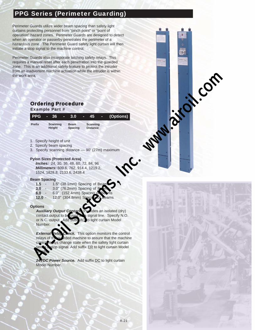
Perimeter Guards utilize wider beam spacing than safety lightcurtains protecting personnel from “pinch point” or “point ofoperation” hazard zones. Perimeter Guards are designed to detectwhen an operator or passerby penetrates the perimeter of ahazardous zone. The Perimeter Guard safety light curtain will theninitiate a stop signal to the machine control.
Perimeter Guards also incorporate latching safety relays. Thisrequires a manual reset after each penetration into the guardedzone. This is an additional safety feature to protect the intruderfrom an inadvertent machine actuation while the intruder is withinthe work area.
PPG Series (Perimeter Guarding)
OrOrOrOrOrdering Prdering Prdering Prdering Prdering ProcedurocedurocedurocedurocedureeeeeExample Part #
Prefix ScanningHeight
ScanningDistance
BeamSpacing
PPG - 36 - 3.0 - 45 - (Options)
1. Specify height of unit2. Specify beam spacing3. Specify scanning distance — 90' (27m) maximum
Pylon Sizes (Protected Area) Inches: 24, 30, 36, 48, 60, 72, 84, 96 Millimeters: 609.6, 762, 914.4, 1219.2, 1524, 1828.8, 2133.6, 2438.4
Beam Spacing1.5 - 1.5" (38.1mm) Spacing of Beams3.0 - 3.0" (76.2mm) Spacing of Beams6.0 - 6.0" (152.4mm) Spacing of Beams12.0 - 12.0" (304.8mm) Spacing of Beams
OptionsAuxiliary Output Contact. Provides an isolated (dry)contact output to be used as a signal line. Specify N.O.or N.C. output. Add suffix AO to light curtain ModelNumber.
External Relay Check. This option monitors the controlrelays of the guarded machine to assure that the machinecontrol relays change state when the safety light curtainsends a stop signal. Add suffix ER to light curtain ModelNumber.
24VDC Power Source. Add suffix DC to light curtainModel Number.
A-21
Air-O
il Sy
stems,
Inc.
www.a
iroil.co
m

All ModelsDim A 3.00" (76mm)Dim B 4.25" (108mm)Dim C 1.00" (25mm)Dim D 1.87" (48mm)Dim E 0.62" (16mm)Dim F 1.00" (25mm)Dim G 1.00" (25mm)Dim I 3.25" (83mm)Dim J 0.62" (16mm)Dim M 4.25" (108mm)
Dim H Dim K Dim LModel (box length) (last to end) (first to last beam)PPG-24 28.87" (733mm) 1.87" (48mm) 25.22" (641mm)PPG-30 36.25" (921mm) 2.87" (73mm) 31.52" (801mm)PPG-36 42.12" (1070mm) 2.87" (73mm) 37.82" (961mm)PPG-42 48.37" (1229mm) 2.87" (73mm) 44.12" (1121mm)PPG-48 54.75" (1391mm) 2.87" (73mm) 50.42" (1281mm)PPG-60 67.25" (1708mm) 2.87" (73mm) 63.02" (1601mm)PPG-72 79.75" (2026mm) 2.87" (73mm) 75.62" (1921mm)PPG-84 91.75" (2330mm) 2.87" (73mm) 88.22" (2241mm)PPG-96 103.75" (2635mm) 2.87" (73mm) 100.82" (2561mm)
Receiver Pylon
Emitter Pylon
PPG Series Dimensions
A-22
Air-O
il Sy
stems,
Inc.
www.a
iroil.co
m

Safe
ty L
ight
Cur
tain
s“A
sys
tem
des
igne
d sp
ecif
ical
ly f
or y
our
mac
hine
gua
rdin
g ne
eds.
”
Des
crip
tion
Con
trol
ler
Enc
losu
re
Pyl
on C
onst
ruct
ion
Inpu
t V
olta
ges
Size
s
Bea
m S
paci
ng
Bla
nkin
g St
yle
-
Aut
o B
lank
-
Flo
atin
g B
lank
Scan
ning
Ran
ges
War
rant
y
“Thi
n Pr
ofile
” w
ith N
ema
12 (
IP 6
4) E
nclo
sure
and
two
Qui
ck D
isco
nnec
tca
bles
Met
al B
ox
Alu
min
um E
xtru
sion
NE
MA
4 (I
P 65
)12
0VA
C, 2
4VD
C, 2
20V
AC
4”(1
02m
m) -
120”
(3,0
48m
m)
in 4
” (1
02m
m) i
ncre
men
ts
1/2”
(13m
m) o
r 1”
(25m
m)
beam
cen
ters
yes
yes
1’-5
0’ (
.3-1
6m)
2 Y
ears
“Thi
n Pr
ofile
” w
ith“I
ntel
ligen
t Saf
ety
Rel
ay”
DIN
-rai
l Con
trol
ler a
nd 2
2’(6
,705
mm
) Qui
ck D
isco
nnec
tca
bles
Gra
y Po
lyca
rbon
ate
(IP
40)
UL
94 V
-1A
lum
inum
Ext
rusi
onN
EM
A 4
(IP
65)
24V
DC
4”(1
02m
m) -
120”
(3,0
48m
m)
in 4
” (1
02m
m) i
ncre
men
ts
1/2”
(13m
m) o
r 1”
(25m
m)
beam
cen
ters
yes
yes
1’-5
0’ (
.3-1
6m)
2 Y
ears
“Thi
n Pr
ofile
” w
ith S
olid
-St
ate
Out
puts
and
two
21’
(6,0
96m
m) Q
uick
Dis
conn
ect
cabl
es w
ithm
ulti-
dire
ctio
nal p
igta
ilsN
/A
Alu
min
um E
xtru
sion
NE
MA
4 (I
P 65
)24
VD
C4”
(102
mm
) -12
0” (3
,048
mm
)
in 4
” (1
02m
m) i
ncre
men
ts
1/2”
(13m
m),
1” (2
5mm
)
or 4
” (1
02m
m) b
eam
cen
ters
yes
yes
1’-5
0’ (.
3-16
m)
1 Y
ear
sale
s@pi
nnac
lesy
stem
s.co
mT
oll F
ree:
(800
) 569
-769
7P
hone
: (41
2) 2
62-3
950
Fax
: (41
2) 2
62-4
055
Mad
e in
USA
Safe
ty L
ight
Cur
tain
s
Safe
ty M
at S
yste
ms
Erg
onom
ic P
alm
But
tons
Pun
ch P
ress
Aut
omat
ion
Con
trol
s P
unch
Pre
ss G
uard
s an
d C
ontr
ols
Pre
ss B
rake
Gua
rds
and
Con
trol
s
R
obot
ic, A
utom
atio
n an
dSp
ecia
l Mac
hine
Gua
rdin
g Sy
stem
s
Add
ition
al P
rodu
cts
Ava
ilabl
e
Mod
el M
G
M
odel
DR
Mod
el S
S
Air-O
il Sy
stems,
Inc.
www.a
iroil.co
m
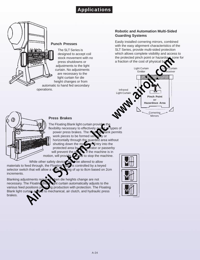
Punch Presses
The SLT Series isdesigned to accept coilstock movement with nopress shutdowns or
adjustments to the lightcurtain. No adjustments
are necessary to thelight curtain for die
height changes or fromautomatic to hand fed secondary
operations.
Robotic and Automation Multi-SidedGuarding Systems
Easily installed cornering mirrors, combinedwith the easy alignment characteristics of theSLT Series, provide multi-sided protectionwhich allows complete visibility and access tothe protected pinch point or hazardous zone fora fraction of the cost of physical barriers.
Press Brakes
The Floating Blank light curtain provides theflexibility necessary to effectively guard all types of
power press brakes. The Floating Blank permitswork pieces to be formed vertically orhorizontally through the guarded area withoutshutting down the machine. Entry into theprotected area by the operator or passerby
will prevent the start or, if the machine is inmotion, will provide a signal to stop the machine.
While other safety devices must be altered to allowmaterials to feed through, the Floating Blank is controlled by a keyedselector switch that will allow a work opening of up to 8cm based on 2cmincrements.
Blanking adjustments required when die heights change are notnecessary. The Floating Blank light curtain automatically adjusts to thevarious feed positions providing production with protection. The FloatingBlank light curtain adapts to mechanical, air clutch, and hydraulic pressbrakes.
Applications
Pinch Pointor
Hazardous Area
Light CurtainEmitter
Light CurtainReceiver
CorneringMirrors
InfraredLight Curtain
A-24
Air-O
il Sy
stems,
Inc.
www.a
iroil.co
m
The effective sensing field of the device shall be located at a distance from the nearest recognized hazards such that the operator or otherscannot reach the hazard with a hand or other body part before cessation of motion during the hazardous portion of the machine cycle.
The point at which a device responds to an intrusion may vary. The devices should be located or adjusted such that the device alwaysresponds to the intrusion at or prior to the safety distance. Care should be exercised when installing the device to ensure that it does notdetect false signals from other devices in the area.
Usually the electro-optical presence-sensing device is used in a manner that provides a protected zone in front of the primary work area withauxiliary devices or guards used to protect secondary access areas. In some cases, however, mirrors may be used in conjunction with thedevice to provide 2-, 3-, 4-, or 5-sided protection.
The machine stop time should be measured with the machine running at its fastest speed with its heaviest die or tooling and the stoptime being measured at the 90° position in the downstroke.
The following formula should be used when calculating the safety distance:
Ds = K x (Ts + Tc + Tr + Tbm) + D(pf)
Ds = Minimum safety distance between the device and the nearest point of operation hazard (in inches).K = Hand speed constant. This value has been determined by various studies and, although these studies indicate speeds of
63 in/sec to over 100 in/sec, they are not conclusive determinations. The employer should determine this value byconsidering all factors, including physical ability of the operator.
Ts = Stop time of the machine tool measured by a stop time measurement device.Tc = Response time of the control system (usually is taken care of by the measurement device).Tr = Response time of the presence-sending device and it’s interface, if any, as stated by the manufacturer or measured by the
employer.Tbm = Additional time allowed for the brake monitor to compensate for variations in normal stopping time.D(pf) = Depth Penetration Factor. Added distance as indicated by the above chart. The minimum object sensitivity is stated by
the manufacturer.
Formula for Calculating Light Curtain Safety Distance
MinimumObject
Sensitivity
D(pf)
A-25
Air-O
il Sy
stems,
Inc.
www.a
iroil.co
m

SmartMats™ Available Yes NoPPPPPinnacinnacinnacinnacinnacle Safle Safle Safle Safle Safety Maety Maety Maety Maety MatststststsWe offer the largest selection of safety mat styles and sizes available in the world.
Customized shapes and sizes are our specialty.
Highest level of Monitored at theMonitoring available level of a normally
Open SPST four-wire
Dead Zones None/100% Active None/100% Active
Active Edging Yes YesPlace mats side-to-side or end-to-end by slidingan active coupler in place; eliminates thresholds,close-out, and uniting strips. Prevents dead zones.
Customized Activation Thresholds Available Yes Yes
Customized Mat Sizes Available Yes Yes
Types of Controllers Available:Metal Box Controller Yes YesDIN-rail Controller Yes Yes
Multi-Lingual Controller with Built-InDiagnostic Message Display Yes Yes
Maximum Intermittent Load on Mat 3000 PSI 3000 PSI
Meets or Exceeds all current standards of OSHA, Yes YesANSI, CSA, and RIA, including the European 1760-1Standard used for CE acceptance
Category 4 Safety System Controller Pulsed Mat Monitoring Yes
Category 3 Safety System Yes Yes
Utilizes the Patented STTS Sensor Technology Yes No
Designed Specifically for the RigorousIndustrial Environment Yes Yes
“Homerun Plug Connector or Wire Capable” Yes Yes
Easy System to Install/Troubleshoot Yes Yes
Welding Safety Mats Available Yes Yes
No Steel Components that Rust or Deform None None
Can Absorb Punctures Yes Yes
Mat Provides Arc-Free Switching Yes Yes
Dual Ribbed Mat Housing Yes Yes
Ribbed, Non-Skid, or High-Temperature/Wet Environment Surfaces Yes Yes
Hermetically Sealed Sensor System Yes Yes
The Mat Electrodes are: Yes YesNon-Corrosive FlexibleNon-Magnetic Anti-Static
Adapts Well to Uneven Factory Floors Yes Yes
Custom Engineered Sensor Systems Available Yes Yes
Computer Interfaced SmartFloors™ andSmartMats™ Available Yes No
STTSSTTSSTTSSTTSSTTS
B-1
Air-O
il Sy
stems,
Inc.
www.a
iroil.co
m
STTSSTTSSTTSSTTSSTTSSafSafSafSafSafety Maety Maety Maety Maety Mat Systemt Systemt Systemt Systemt System
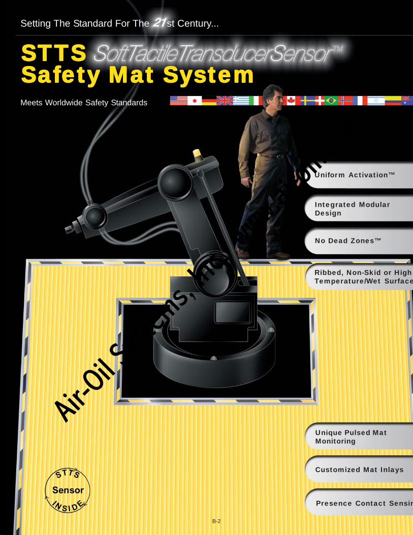
Uniform Activation™
No Dead Zones™
Integrated ModularDesign
Unique Pulsed MatMonitoring
Customized Mat Inlays
Presence Contact Sensin
Meets Worldwide Safety Standards
Setting The Standard For The st Century...
Ribbed, Non-Skid or HighTemperature/Wet Surface
B-2
Air-O
il Sy
stems,
Inc.
www.a
iroil.co
m

The STTS Safety Mat System™ is a technological paradigm in the field of presence-contact sensing/pressure sensitive safety mat systems. This revolutionary mat systemis a hybrid design that combines features to meet and surpass both domestic andinternational safety standards. Through its advanced technology and state-of-the-artdesign features, the STTS Safety Mat System sets a new World Class Standard forthe mat detection industry.
The
STTS system is a tactile sensorthat provides informationregarding the distribution andmagnitude of tactile forceapplied to its surface. Thispatented technology involvesthe continuous and variablemeasuring of tactile forces ofpressure. In some respects,tactile sensing for electro-mechanical devices isanalogous to the human senseof touch--information about theamount and distribution oftactile pressure over a surfacecan be received andtransmitted. When an objectcomes in contact with thesensor, tactile sensingprovides information about theobject's shape, texture,position, orientation,deformation, center of mass,and presence of torque orslippage. If you have specialneeds or applications for usesof the technology, please
contact the factory for ourintelligent products.
Unique Pulsed MatUnique Pulsed MatUnique Pulsed MatUnique Pulsed MatUnique Pulsed MatMonitoringMonitoringMonitoringMonitoringMonitoringAll STTS mats are homerunwired back to the controller andare continuously pulsed. Thisverifies that each safety mat iswired properly and is connectedto the mat controller. Unlikeopen switch steel mat systemsthe STTS controller pulses &monitors the safety system.This verifies that the mat wiringhas not been bypassed,jumpered or shorted outside ofthe control box and preventsagainst an automatic reset ofthe control (green) with anunsafe condition present.
Each STTS mat in the safetysystem has a specific value andaddress that must be
recognized and verified as theSTTS controller monitors thesafety zone. The STTScontinuous pulsed monitoringsystem provides a higher levelof safety mat guarding. Thispulsed system eliminates thepossibility of wire tampering orjumpering out of safety mats vs.open switch non-pulsedsystems.
This feature provides a uniformactivation threshold (on/offsignal) throughout the entire matsurface area. Our uniquedesign of uniform activationalso provides a guardingsystem that contains no deadzones. This provides the userwith a much safer guardingsystem as well as compliancewith domestic and internationalstandards.
B-3
par•a•digm (par’ dim,-dim), noun 1. an example servingas a model; pattern: 2. in technology; a hybrid product that possesses advancedtechnological advantages and inherent design features over current products andtechnologies in the marketplace...the
e
STTSSTTSSTTSSTTSSTTSSafetyMatSystemTM
STTSSoft Tactile TransducerSensorTM Technology
Why the STTSSAFETY MAT SYSTEMTM
is the safest
Uniform ActivationTM
Air-O
il Sy
stems,
Inc.
www.a
iroil.co
m
Uniform activation means thatthe “STTS SAFETY MATSYSTEM” has no dead zoneson the mat surface--it is 100%ACTIVE. Other mats that usedouble-backed foam tape, O-rings, or large perimeter seal-ing techniques for elementencasement create a deadzone around the entire perim-eter of the product. Deadzones are also found directlyabove and below the manysilicone spacers, elastomers,or insulators used as standoffswithin the element assembly offorce style mats. With theadvent of specific safety matpositioning and layout formulasbased on international safety
standards, the “STTS SAFETYMAT SYSTEM” gives you thepeace of mind of a mat detec-tion system with no dead zones.
An “Intelligent Mat” is the sameas the standard STTS safetymat--with the addition of apressure-activated, “on/off”analog-controlled switch sen-sor, for areas based on force/area (psi). An “Intelligent Mat”provides a broad understandingof the kind of tactile event that isoccurring and, in the same wayas the standard mat, is scalablebecause of its analog outputand natural psi characteristics.
What makes the “Intelligent Mat”unique is that it can be pro-grammed by varying the elec-trode pattern to determine wherethe contact has occurred on amultiple position basis (in width“x” and length “y”), and the basisof mass point loading (“z”).
This standard feature of the“STTS SAFETY MAT SYSTEM”enables the user to place themats side-to-side or end-to-end.Simply sliding the active couplerin place enables the active edg-ing feature of the “STTS SAFETYMAT SYSTEM.”This solves cumbersome mul-tiple mat installation problemsnormally associated with mats.It also eliminates the need forthresholds, closeout and unitingstrips that create dead zones,which increase substantiallyboth product costs and installa-tion time.
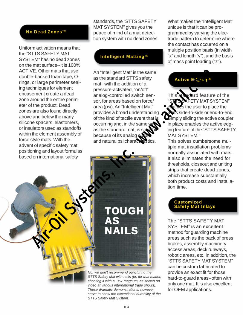
The “STTS SAFETY MATSYSTEM” is an excellentmethod for guarding machineareas such as the back of pressbrakes, assembly machineryaccess areas, deck runways,robotic areas, etc. In addition, the“STTS SAFETY MAT SYSTEM”can be custom fabricated toprovide an exact fit for thosehard-to-guard areas--often withonly one mat. It is also excellentfor OEM applications.
TTTTTOUGHOUGHOUGHOUGHOUGHASASASASASNNNNNAILSAILSAILSAILSAILS
No, we don’t recommend puncturing theSTTS Safety Mat with nails (or, for that matter,shooting it with a .357 magnum, as shown onvideo at various international trade shows).These dramatic demonstrations, however,serve to show the exceptional durability of theSTTS Safety Mat System.
B-4
No Dead ZonesTM
Intelligent MattingTM
Active EdgingTM
CustomizedSafety Mat Inlays
Air-O
il Sy
stems,
Inc.
www.a
iroil.co
m
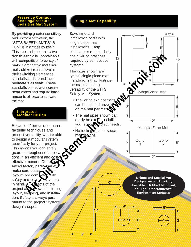
By providing greater sensitivityand uniform activation, the“STTS SAFETY MAT SYS-TEM” is in a class by itself.This true and uniform activa-tion threshold is unobtainablewith competitive “force-style”mats. Competitive mats nor-mally utilize insulators withintheir switching element asstandoffs and around theirperimeters as seals. Thesestandoffs or insulators createdead zones and require largeamounts of force to activatethe mat.
Because of our unique manu-facturing techniques andproduct versatility, we are ableto design a modular systemspecifically for your project.This means you can safelyguard the toughest of applica-tions in an efficient and cost-effective manner. Our experi-enced factory personnel willmake sure detailed systemlayouts are completed withsafety and cost-effectivenessin mind. All aspects of theproject are reviewed includinglayout, shipping, and installa-tion. Safety is always para-mount to the project "systemdesign" scope.
B-5
Presence ContactSensing/PressureSensitive Mat System
IntegratedModular Design
Save time andinstallation costs withsingle piece matinstallations. Helpeliminate or reduce daisychain wiring practicesrequired by competitivesystems.
The sizes shown aretypical single piece matinstallations that illustratethe manufacturingversatility of the STTSSafety Mat System.
• The wiring exit positionscan be located anywhereon the mat perimeter.
• The mat sizes shown caneasily be altered to fulfillyour specific project needs.
• No tooling fees for specialmat designs.
Single Mat Capability
Unique and Special MatDesigns are our Specialty.
Available in Ribbed, Non-Skid,or High Temperature/Wet
Environment SurfacesAir-O
il Sy
stems,
Inc.
www.a
iroil.co
m

• "Control Reliable" Safety Mat System incorporates unique Pulsed Mat Monitoring
• Utilizes the patented STTS sensor technology
• Designed specifically for the rigorous industrialenvironment
• Provides "Uniform Activation™"
• Contains "No Dead Zones™” – 100% Active MatSurface
• "Active Edging™" feature
• "Intelligent Matting™" capability
• "Homerun plug connector or wire capable"
• Multi-lingual mat controller with built-in diagnosticmessage display available
• A true uniform pressure sensitive (PSI) mat system
• Easy system to install/Easy to troubleshoot
• No adjustments required
• Contains no steel components to rust or deform
• No vacuum seal to break which induces rust andleads to dead zones
• Can absorb punctures
• Mat provides arc-free switching
• Dual ribbed mat housing
• Ribbed, non-skid, or high temperature/wetenvironment surfaces
• Hermetically sealed sensor system
• The STTS Mat Electrodes are:Non-Corrosive FlexibleNon-Magnetic ArcFreeAnti-Static Non-Metallic
• Adapts well to uneven factory floors
• Custom engineered sensor systems available
• Customized activation thresholds available
• Largest selection of sizes and capabilities available
• Intelligent floors and mats (zone/force sensitiverelationships)
• Computer interfaced SmartFloors™ andSmartMats™ available
• Multiple patents pending
• High-temp/non-skid welding safety mat
STTS Safety Mat System™
B-6
STTSSystem
Yes _____ _____
Yes _____ _____
Yes _____ _____
Yes _____ _____
Yes _____ _____
Yes _____ _____
Yes _____ _____
Yes _____ _____
Yes _____ _____
Yes _____ _____
Yes _____ _____
Yes _____ _____
Yes _____ _____
Yes _____ _____
Yes _____ _____
Yes _____ _____
Yes _____ _____
Yes _____ _____
Yes _____ _____
Yes _____ _____
Yes _____ _____
Yes _____ _____
Yes _____ _____
Yes _____ _____
Yes _____ _____
Yes _____ _____
Yes _____ _____
Design Criteria
Yes _____ _____NEW!
Air-O
il Sy
stems,
Inc.
www.a
iroil.co
m
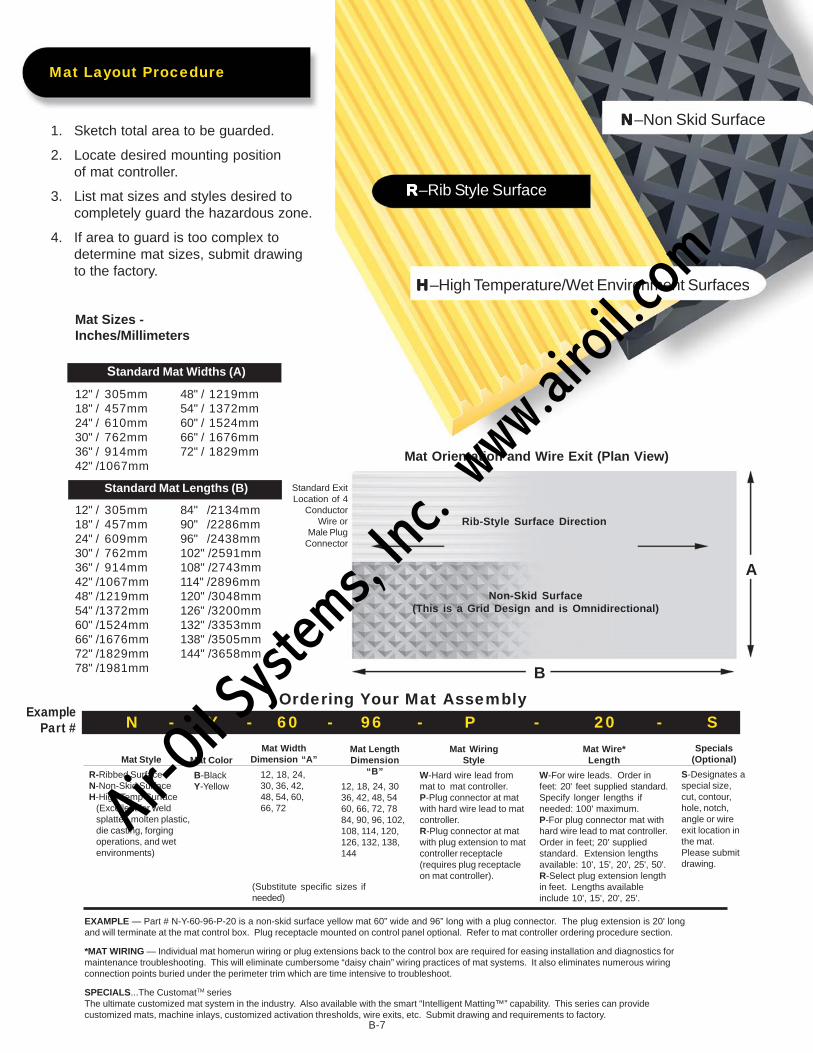
1. Sketch total area to be guarded.
2. Locate desired mounting positionof mat controller.
3. List mat sizes and styles desired tocompletely guard the hazardous zone.
4. If area to guard is too complex todetermine mat sizes, submit drawingto the factory.
Mat Sizes -Inches/Millimeters
Standard Mat Widths (A)
12" / 305mm 48" / 1219mm18" / 457mm 54" / 1372mm24" / 610mm 60" / 1524mm30" / 762mm 66" / 1676mm36" / 914mm 72" / 1829mm42" /1067mm
Standard Mat Lengths (B)
12" / 305mm 84" /2134mm18" / 457mm 90" /2286mm24" / 609mm 96" /2438mm30" / 762mm 102" /2591mm36" / 914mm 108" /2743mm42" /1067mm 114" /2896mm48" /1219mm 120" /3048mm54" /1372mm 126" /3200mm60" /1524mm 132" /3353mm66" /1676mm 138" /3505mm72" /1829mm 144" /3658mm78" /1981mm
EXAMPLE — Part # N-Y-60-96-P-20 is a non-skid surface yellow mat 60” wide and 96” long with a plug connector. The plug extension is 20' longand will terminate at the mat control box. Plug receptacle mounted on control panel optional. Refer to mat controller ordering procedure section.
*MAT WIRING — Individual mat homerun wiring or plug extensions back to the control box are required for easing installation and diagnostics formaintenance troubleshooting. This will eliminate cumbersome “daisy chain” wiring practices of mat systems. It also eliminates numerous wiringconnection points buried under the perimeter trim which are time intensive to troubleshoot.
SPECIALS...The CustomatTM seriesThe ultimate customized mat system in the industry. Also available with the smart “Intelligent Matting™” capability. This series can providecustomized mats, machine inlays, customized activation thresholds, wire exits, etc. Submit drawing and requirements to factory.
B-7
Mat Layout Procedure
NNNNN–Non Skid Surface
RRRRR–Rib Style Surface
Mat Orientation and Wire Exit (Plan View)
Rib-Style Surface Direction
Non-Skid Surface(This is a Grid Design and is Omnidirectional)
Standard ExitLocation of 4
ConductorWire or
Male PlugConnector
B
A
Mat Wire*Length
W-For wire leads. Order infeet: 20' feet supplied standard.Specify longer lengths ifneeded: 100' maximum.P-For plug connector mat withhard wire lead to mat controller.Order in feet; 20' suppliedstandard. Extension lengthsavailable: 10', 15', 20', 25', 50'.R-Select plug extension lengthin feet. Lengths availableinclude 10', 15', 20', 25'.
Mat Style
R-Ribbed SurfaceN-Non-Skid SurfaceH-High Temp Surface
(Excellent for weldsplatter, molten plastic,die casting, forgingoperations, and wetenvironments)
Mat Color
B-BlackY-Yellow
Mat WidthDimension “A”
12, 18, 24,30, 36, 42,48, 54, 60,66, 72
Mat LengthDimension
“B”
12, 18, 24, 3036, 42, 48, 5460, 66, 72, 7884, 90, 96, 102,108, 114, 120,126, 132, 138,144
Mat WiringStyle
W-Hard wire lead frommat to mat controller.P-Plug connector at matwith hard wire lead to matcontroller.R-Plug connector at matwith plug extension to matcontroller receptacle(requires plug receptacleon mat controller).
Specials(Optional)
S-Designates aspecial size,cut, contour,hole, notch,angle or wireexit location inthe mat.Please submitdrawing.
N - Y - 60 - 96 - P - 20 - SExample
Part #
(Substitute specific sizes ifneeded)
Ordering Your Mat Assembly
HHHHH–High Temperature/Wet Environment Surfaces
Air-O
il Sy
stems,
Inc.
www.a
iroil.co
m

Perimeter Trim (Part #M001) isused for anchoring the outsideperimeter of the safety mat assem-bly to the floor and to run the matwiring back to a location near themat controller. The unique wireraceway is built into the perimetertrim and is supplied standard withall Part #M001 orders. Theperimeter trim adds 2.5" (64mm)to mat dimension per edge.
Ordering Procedure: Specifylinear feet or dimensions followed byone of the following:
TK: (picture frame trim kit)M001: (bulk)M001-M: (bulk/machined)Custom Trim Kit: (consult factory)
Example: Part # 2442TKA 24" x 42" mat with a 24" x 42"picture frame trim kit; total areais 29" x 47".
Built-in Wire Raceway(Part # M002)
This innovative design concept providesexcellent wiring protection for your safety matsystem. The design provides an elevated offthe floor wire raceway to protect the wiringand connections from fluids and causticmaterials on the floor. It also provides awiring harness to protect the mat wires frombeing pinched by improper perimeter triminstallations commonly found in the industry.
The built-in raceway promotes individualhomerun mat wiring back to the mat control-ler to ease installation and aid systemtroubleshooting diagnostics via the messagedisplay. The wire raceway provides enoughspace for six wire/plug assemblies to be runindividually within the raceway back to themat controller. The wire raceway componentis supplied standard with the perimeter trimPart #M001.
ALL SAFETY MAT ASSEMBLIES ARE REQUIRED BY LAW TO BE “FIXED” INPROPER LOCATION FOR MACHINE GUARDING APPLICATIONS.
Surface Metal RacewayUsed to shield wire runs across the floor between the perimeter trim and the matcontroller.
PPPPPararararar tttttNo.No.No.No.No. ItemItemItemItemItem DescriptionDescriptionDescriptionDescriptionDescription
M005
M006
Baseand
Cover
Baseand
Cover
.040" (1mm) galvanized steel.Base has 9/32" (7mm) diametermounting holes on centers ofapproximately 8" (203mm) and isscored every 3" (76mm).Available in 10’ (3.05m) lengths.
Wire Capacity - 1 to 4 Mat Wires
Cover: .050" (1mm) galvanizedsteel.Base: .040" (1mm) galvanizedsteel. Base has 9/32" (7mm)mounting holes on centers ofapproximately 8" (203mm) and isscored every 3" (76mm).Available in 10’ (3.05m) lengths.
Wire Capacity--5 to 8 Mat Wires
Ordering Procedure — Specify Part # and total length required in feet.
B-8
Trim Kits for Mats
Recessed Areafor 1” (25mm)
Colored Safety Marking
Perimeter TrimPart #M001
Aluminum Active CouplerPart #M003
MAT
Typical Cross SectionView of Mat Assembly
Built-in Wire RacewayPart # M002
Active Coupler (Part #M003) is usedwhenever the mats are placed side to side orend to end. This will activate the "ActiveEdgingTM" feature which will eliminate deadzones between mats. The active coupleradds .25" (6.35mm) to the mat system’soverall dimension.Ordering Procedure - Specify Part # andtotal length required in feet.
Air-O
il Sy
stems,
Inc.
www.a
iroil.co
m
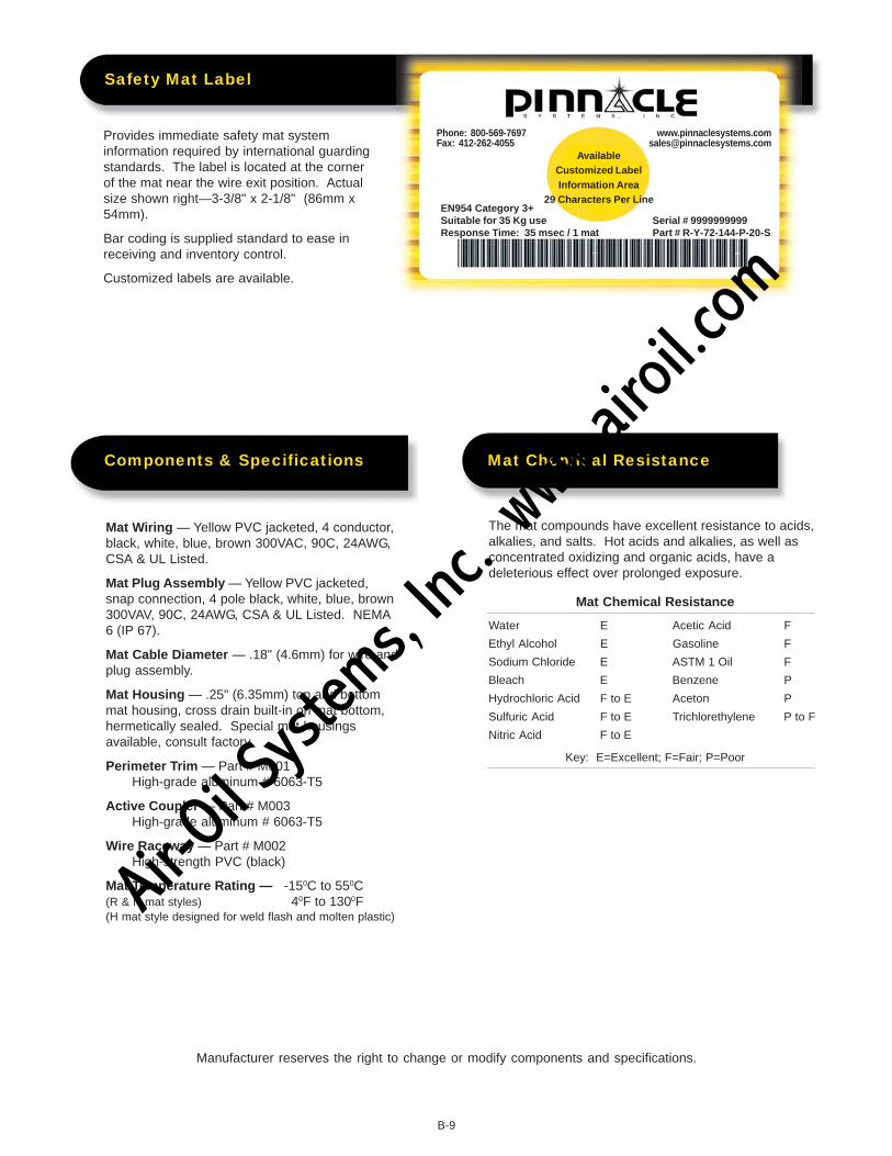
Provides immediate safety mat systeminformation required by international guardingstandards. The label is located at the cornerof the mat near the wire exit position. Actualsize shown right—3-3/8" x 2-1/8" (86mm x54mm).
Bar coding is supplied standard to ease inreceiving and inventory control.
Customized labels are available.
Mat Wiring — Yellow PVC jacketed, 4 conductor,black, white, blue, brown 300VAC, 90C, 24AWG,CSA & UL Listed.
Mat Plug Assembly — Yellow PVC jacketed,snap connection, 4 pole black, white, blue, brown300VAV, 90C, 24AWG, CSA & UL Listed. NEMA6 (IP 67).
Mat Cable Diameter — .18" (4.6mm) for wire andplug assembly.
Mat Housing — .25" (6.35mm) top and bottommat housing, cross drain built-in on mat bottom,hermetically sealed. Special mat housingsavailable, consult factory.
Perimeter Trim — Part # M001High-grade aluminum # 6063-T5
Active Coupler — Part # M003High-grade aluminum # 6063-T5
Wire Raceway — Part # M002High-strength PVC (black)
Mat Temperature Rating — -150C to 550C(R & N mat styles) 40F to 1300F(H mat style designed for weld flash and molten plastic)
The mat compounds have excellent resistance to acids,alkalies, and salts. Hot acids and alkalies, as well asconcentrated oxidizing and organic acids, have adeleterious effect over prolonged exposure.
Mat Chemical Resistance
Water E Acetic Acid F
Ethyl Alcohol E Gasoline F
Sodium Chloride E ASTM 1 Oil F
Bleach E Benzene P
Hydrochloric Acid F to E Aceton P
Sulfuric Acid F to E Trichlorethylene P to F
Nitric Acid F to E
Key: E=Excellent; F=Fair; P=Poor
Safety Mat Label
Components & Specifications Mat Chemical Resistance
AvailableCustomized LabelInformation Area
29 Characters Per Line
Serial # 9999999999Part # R-Y-72-144-P-20-S
EN954 Category 3+Suitable for 35 Kg useResponse Time: 35 msec / 1 mat
Phone: 800-569-7697Fax: 412-262-4055
B-9
Manufacturer reserves the right to change or modify components and specifications.
Air-O
il Sy
stems,
Inc.
www.a
iroil.co
m
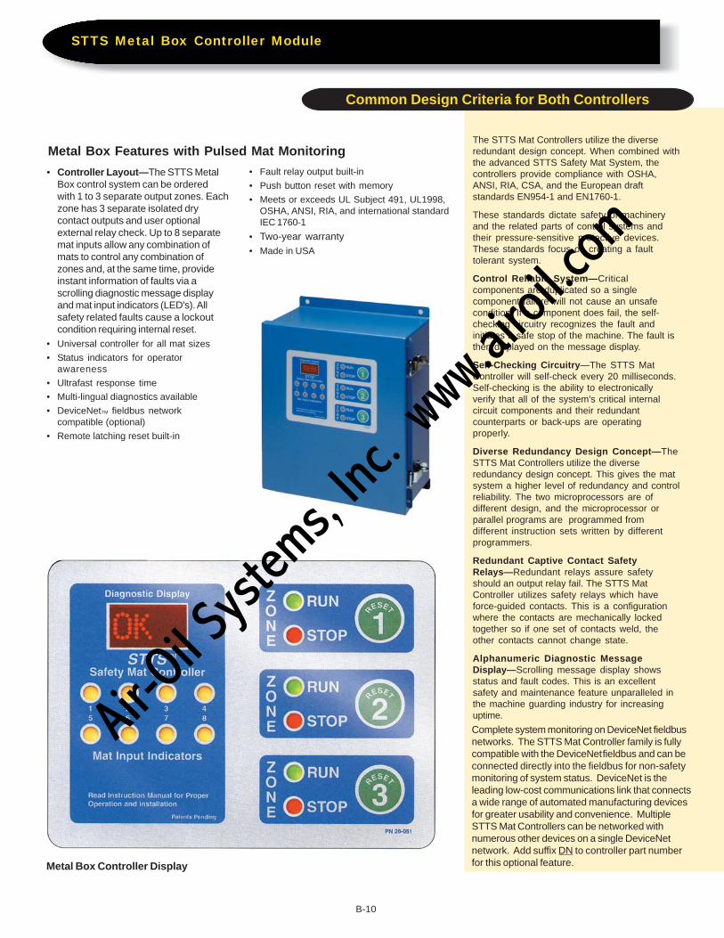
Complete system monitoring on DeviceNet fieldbusnetworks. The STTS Mat Controller family is fullycompatible with the DeviceNet fieldbus and can beconnected directly into the fieldbus for non-safetymonitoring of system status. DeviceNet is theleading low-cost communications link that connectsa wide range of automated manufacturing devicesfor greater usability and convenience. MultipleSTTS Mat Controllers can be networked withnumerous other devices on a single DeviceNetnetwork. Add suffix DN to controller part numberfor this optional feature.
The STTS Mat Controllers utilize the diverseredundant design concept. When combined withthe advanced STTS Safety Mat System, thecontrollers provide compliance with OSHA,ANSI, RIA, CSA, and the European draftstandards EN954-1 and EN1760-1.
These standards dictate safety of machineryand the related parts of control systems andtheir pressure-sensitive protective devices.These standards focus on creating a faulttolerant system.
Control Reliable System—Criticalcomponents are duplicated so a singlecomponent failure will not cause an unsafecondition. If a component does fail, the self-checking circuitry recognizes the fault andinitiates a safe stop of the machine. The fault isthen displayed on the message display.
Self-Checking Circuitry—The STTS MatController will self-check every 20 milliseconds.Self-checking is the ability to electronicallyverify that all of the system's critical internalcircuit components and their redundantcounterparts or back-ups are operatingproperly.
Diverse Redundancy Design Concept—TheSTTS Mat Controllers utilize the diverseredundancy design concept. This gives the matsystem a higher level of redundancy and controlreliability. The two microprocessors are ofdifferent design, and the microprocessor orparallel programs are programmed fromdifferent instruction sets written by differentprogrammers.
Redundant Captive Contact SafetyRelays—Redundant relays assure safetyshould an output relay fail. The STTS MatController utilizes safety relays which haveforce-guided contacts. This is a configurationwhere the contacts are mechanically lockedtogether so if one set of contacts weld, theother contacts cannot change state.
Alphanumeric Diagnostic MessageDisplay—Scrolling message display showsstatus and fault codes. This is an excellentsafety and maintenance feature unparalleled inthe machine guarding industry for increasinguptime.
• Controller Layout—The STTS MetalBox control system can be orderedwith 1 to 3 separate output zones. Eachzone has 3 separate isolated drycontact outputs and user optionalexternal relay check. Up to 8 separatemat inputs allow any combination ofmats to control any combination ofzones and, at the same time, provideinstant information of faults via ascrolling diagnostic message displayand mat input indicators (LED's). Allsafety related faults cause a lockoutcondition requiring internal reset.
• Universal controller for all mat sizes
• Status indicators for operatorawareness
• Ultrafast response time
• Multi-lingual diagnostics available
• DeviceNetTM fieldbus networkcompatible (optional)
• Remote latching reset built-in
Metal Box Features with Pulsed Mat Monitoring
Metal Box Controller Display
• Fault relay output built-in
• Push button reset with memory
• Meets or exceeds UL Subject 491, UL1998,OSHA, ANSI, RIA, and international standardIEC 1760-1
• Two-year warranty• Made in USA
STTS Metal Box Controller Module
Common Design Criteria for Both Controllers
B-10
Air-O
il Sy
stems,
Inc.
www.a
iroil.co
m
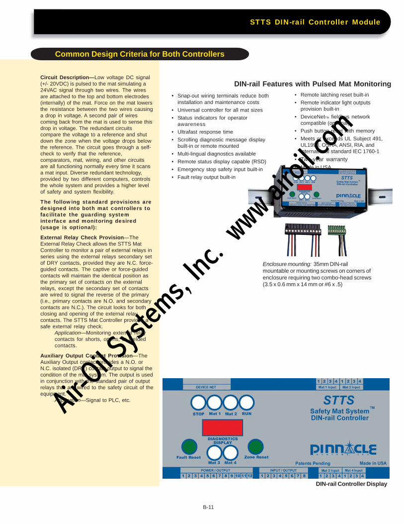
• Snap-out wiring terminals reduce bothinstallation and maintenance costs
• Universal controller for all mat sizes
• Status indicators for operatorawareness
• Ultrafast response time
• Scrolling diagnostic message displaybuilt-in or remote mounted
• Multi-lingual diagnostics available
• Remote status display capable (RSD)
• Emergency stop safety input built-in
• Fault relay output built-in
Circuit Description—Low voltage DC signal(+/- 20VDC) is pulsed to the mat simulating a24VAC signal through two wires. The wiresare attached to the top and bottom electrodes(internally) of the mat. Force on the mat lowersthe resistance between the two wires causinga drop in voltage. A second pair of wirescoming back from the mat is used to sense thisdrop in voltage. The redundant circuitscompare the voltage to a reference and shutdown the zone when the voltage drops belowthe reference. The circuit goes through a self-check to verify that the reference,comparators, mat, wiring, and other circuitsare all functioning normally every time it scansa mat input. Diverse redundant technology,provided by two different computers, controlsthe whole system and provides a higher levelof safety and system flexibility.
The following standard provisions aredesigned into both mat controllers tofacilitate the guarding systeminterface and monitoring desired(usage is optional):
External Relay Check Provision—TheExternal Relay Check allows the STTS MatController to monitor a pair of external relays inseries using the external relays secondary setof DRY contacts, provided they are N.C. force-guided contacts. The captive or force-guidedcontacts will maintain the identical position asthe primary set of contacts on the externalrelays, except the secondary set of contactsare wired to signal the reverse of the primary(i.e., primary contacts are N.O. and secondarycontacts are N.C.). The circuit looks for bothclosing and opening of the external relaycontacts. The STTS Mat Controller provides asafe external relay check.
Application—Monitoring external relaycontacts for shorts, opens, or weldedcontacts.
Auxiliary Output Contact Provision—TheAuxiliary Output contact provides a N.O. orN.C. isolated (DRY) contact output to signal thecondition of the mat system. The output is usedin conjunction with the standard pair of outputrelays that are wired to the safety circuit of theequipment.
Application—Signal to PLC, etc.
• Remote latching reset built-in
• Remote indicator light outputsprovision built-in
• DeviceNetTM fieldbus networkcompatible (optional)
• Push button reset with memory
• Meets or exceeds UL Subject 491,UL1998, OSHA, ANSI, RIA, andinternational standard IEC 1760-1
• Two-year warranty• Made in USA
DIN-rail Features with Pulsed Mat Monitoring
DIN-rail Controller Display
Enclosure mounting: 35mm DIN-railmountable or mounting screws on corners ofenclosure requiring two combo-head screws(3.5 x 0.6 mm x 14 mm or #6 x .5)
STTS DIN-rail Controller Module
Common Design Criteria for Both Controllers
B-11
Air-O
il Sy
stems,
Inc.
www.a
iroil.co
m
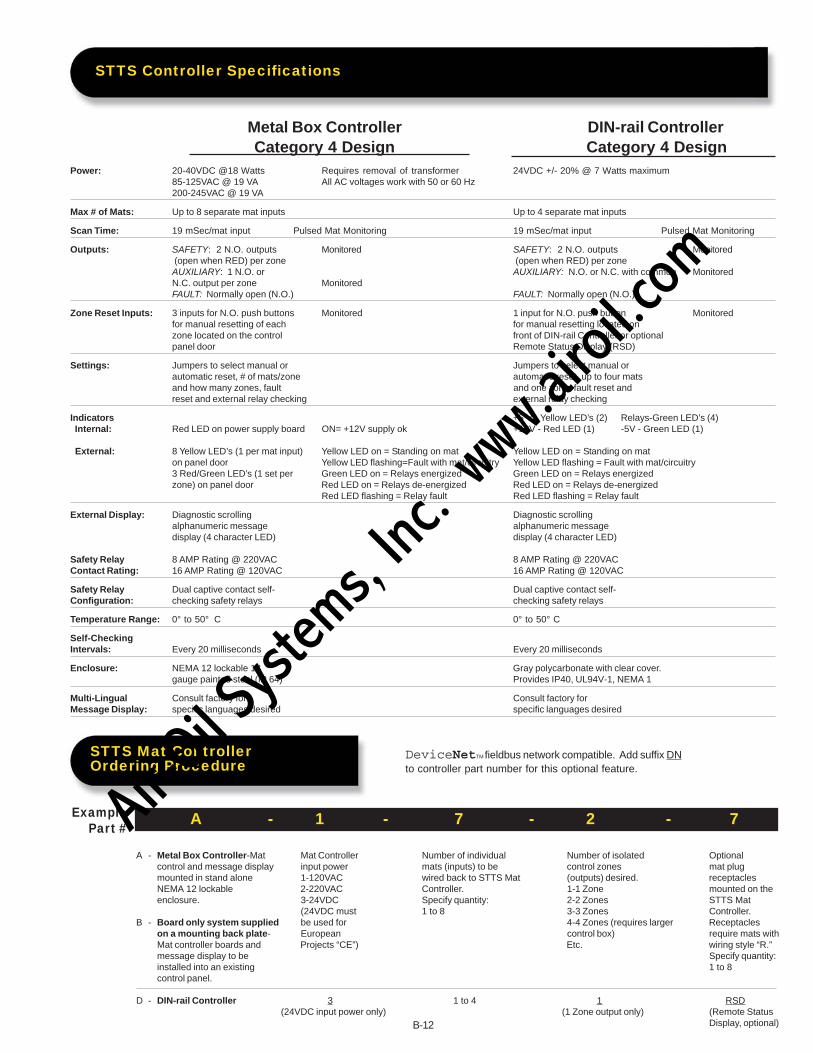
Category 4 Design Category 4 DesignPower: 20-40VDC @18 Watts Requires removal of transformer 24VDC +/- 20% @ 7 Watts maximum
85-125VAC @ 19 VA All AC voltages work with 50 or 60 Hz200-245VAC @ 19 VA
Max # of Mats: Up to 8 separate mat inputs Up to 4 separate mat inputs
Scan Time: 19 mSec/mat input Pulsed Mat Monitoring 19 mSec/mat input Pulsed Mat Monitoring
Outputs: SAFETY: 2 N.O. outputs Monitored SAFETY: 2 N.O. outputs Monitored (open when RED) per zone (open when RED) per zoneAUXILIARY: 1 N.O. or AUXILIARY: N.O. or N.C. with common MonitoredN.C. output per zone MonitoredFAULT: Normally open (N.O.) FAULT: Normally open (N.O.)
Zone Reset Inputs: 3 inputs for N.O. push buttons Monitored 1 input for N.O. push button Monitoredfor manual resetting of each for manual resetting located onzone located on the control front of DIN-rail Controller or optionalpanel door Remote Status Display (RSD)
Settings: Jumpers to select manual or Jumpers to select manual orautomatic reset, # of mats/zone automatic reset, up to four matsand how many zones, fault and one zone, fault reset andreset and external relay checking external relay checking
Indicators +5 V - Yellow LED’s (2) Relays-Green LED’s (4) Internal: Red LED on power supply board ON= +12V supply ok +12V - Red LED (1) -5V - Green LED (1)
External: 8 Yellow LED’s (1 per mat input) Yellow LED on = Standing on mat Yellow LED on = Standing on maton panel door Yellow LED flashing=Fault with mat/circuitry Yellow LED flashing = Fault with mat/circuitry3 Red/Green LED’s (1 set per Green LED on = Relays energized Green LED on = Relays energizedzone) on panel door Red LED on = Relays de-energized Red LED on = Relays de-energized
Red LED flashing = Relay fault Red LED flashing = Relay fault
External Display: Diagnostic scrolling Diagnostic scrollingalphanumeric message alphanumeric messagedisplay (4 character LED) display (4 character LED)
Safety Relay 8 AMP Rating @ 220VAC 8 AMP Rating @ 220VACContact Rating: 16 AMP Rating @ 120VAC 16 AMP Rating @ 120VAC
Safety Relay Dual captive contact self- Dual captive contact self-Configuration: checking safety relays checking safety relays
Temperature Range: 0° to 50° C 0° to 50° C
Self-CheckingIntervals: Every 20 milliseconds Every 20 milliseconds
Enclosure: NEMA 12 lockable 18 Gray polycarbonate with clear cover.gauge painted steel (IP 64) Provides IP40, UL94V-1, NEMA 1
Multi-Lingual Consult factory for Consult factory forMessage Display: specific languages desired specific languages desired
ExamplePart #
A - Metal Box Controller-Mat Mat Controller Number of individual Number of isolated Optionalcontrol and message display input power mats (inputs) to be control zones mat plugmounted in stand alone 1-120VAC wired back to STTS Mat (outputs) desired. receptaclesNEMA 12 lockable 2-220VAC Controller. 1-1 Zone mounted on theenclosure. 3-24VDC Specify quantity: 2-2 Zones STTS Mat
(24VDC must 1 to 8 3-3 Zones Controller.B - Board only system supplied be used for 4-4 Zones (requires larger Receptacles
on a mounting back plate- European control box) require mats withMat controller boards and Projects “CE”) Etc. wiring style “R.”message display to be Specify quantity:installed into an existing 1 to 8control panel.
D - DIN-rail Controller 3 1 to 4 1 RSD(24VDC input power only) (1 Zone output only) (Remote Status
Display, optional)
A - 1 - 7 - 2 - 7
DeviceNetTM fieldbus network compatible. Add suffix DN
to controller part number for this optional feature.
STTS Controller Specifications
STTS Mat ControllerOrdering Procedure
B-12
Metal Box Controller DIN-rail Controller
Air-O
il Sy
stems,
Inc.
www.a
iroil.co
m
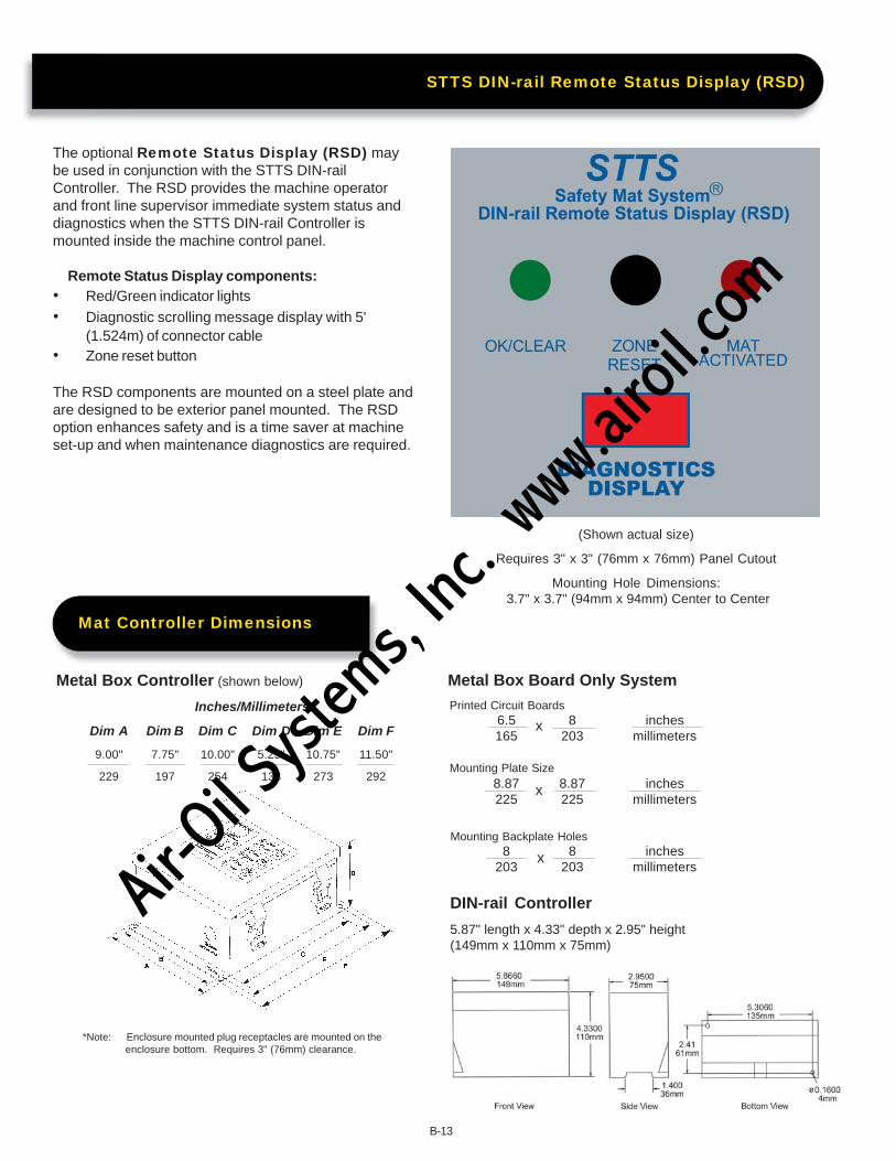
The optional Remote Status Display (RSD) maybe used in conjunction with the STTS DIN-railController. The RSD provides the machine operatorand front line supervisor immediate system status anddiagnostics when the STTS DIN-rail Controller ismounted inside the machine control panel.
Remote Status Display components:• Red/Green indicator lights• Diagnostic scrolling message display with 5'
(1.524m) of connector cable• Zone reset button
The RSD components are mounted on a steel plate andare designed to be exterior panel mounted. The RSDoption enhances safety and is a time saver at machineset-up and when maintenance diagnostics are required.
(Shown actual size)
Requires 3" x 3" (76mm x 76mm) Panel Cutout
Mounting Hole Dimensions: 3.7" x 3.7" (94mm x 94mm) Center to Center
Metal Box Board Only SystemPrinted Circuit Boards
Mounting Plate Size
Mounting Backplate Holes
6.5 8 inches165 203 millimeters
8.87 8.87 inches225 225 millimeters
8 8 inches203 203 millimeters
x
x
x
DIN-rail Controller
5.87" length x 4.33" depth x 2.95" height(149mm x 110mm x 75mm)
*Note: Enclosure mounted plug receptacles are mounted on theenclosure bottom. Requires 3" (76mm) clearance.
Metal Box Controller (shown below)
Inches/Millimeters
Dim A Dim B Dim C Dim D Dim E Dim F
9.00" 7.75" 10.00" 5.25" 10.75" 11.50"
229 197 254 133 273 292
STTS DIN-rail Remote Status Display (RSD)
Mat Controller Dimensions
B-13
Air-O
il Sy
stems,
Inc.
www.a
iroil.co
m

How to Properly Size YourSafety Mat Guarding System
The following formula is aninternational draft guideline forthe proper positioning andapplication of safety mats formachine guarding. This formulamust be followed for all safetymat applications supplied to theEuropean Community (CE)member nations. CEN is theEuropean Committee forStandardization. Final draft#prEN999.
The minimum distance from the dangerzone shall be calculated by using thegeneral formula:
S = (K x T) + C
S is the safety mat minimum distance ininches/millimeters in a horizontal plane,from the danger zone to the detectingedge of the safety mat furthest from thedanger zone.
K is a parameter in inches/millimetersper second, derived from data onapproach speeds of the body or parts ofthe body. K = 63 inches/second or 1600mm/second.
T is the total system stopping timeperformance, which includes activatingthe safety mat, the mat controller outputsignal switching device, and the timerequired to stop the machine andremove risk.
C is an additional distance in inches/millimeters, based on intrusion towardsthe danger zone prior to actuation of theprotective safety mat equipment. C =48" (1219mm).
Annex B (informative)
Walking speeds and stride lengths.The positioning of equiment which isactivated by a person walking into thedetection zone by stepping onto apressure senstive mat is affected byspeed of approach and stride length.The walking speed and stride lengthdepend on the physical andanthropometric data of the population.
Speed of Approach. This standadassumes the approach of personstowards the danger zone will be atwalking speed.
Stride Length. Available researchdata has shown that the 95thpercentile of two steps (i.e., startingand finishing with the same foot)measured from heel contact at walkingspeed is approximately 7" (1905mm).By dividing by two and subtracting the5th percentile shoe length provides astride length of 28" (711mm). If it isassumed that an allowance has to bemade, for example, between thedetection zone and the stride length of2" (50mm) this gives a minimum widthof 30" (762 mm) for the detection zone.
B-14
Sizing Your System
Air-O
il Sy
stems,
Inc.
www.a
iroil.co
m
B-15
Safety Mat Layout Grid Worksheet
Fax to 412-262-4055 for ProposalFax to 412-262-4055 for ProposalFax to 412-262-4055 for ProposalFax to 412-262-4055 for ProposalFax to 412-262-4055 for Proposal
Submitted By:
Name: ___________________________________________________________________
Company: ___________________________________________________________________
Phone Number: ___________________________________________________________________
Fax Number _____________________ Email: ___________________________________
Air-O
il Sy
stems,
Inc.
www.a
iroil.co
m

B-16
Complies with ANSI/RIA StandardR15.06-1999, ANSI/B11.19-1990OSHA 1910.217b, CSA andUL 508 RequirementsDesigned to EN1760-1, EN954-1Category 4 Controllers &EN60204-1 for CE certificationHazardous area presence sensingdetectionCross monitored systemNEMA 6 (IP 67) rated mat systemHigh-grade vinyl plastisol sealed housing
Customized Safety MatSystems are our Specialtyand are available in Ribbed,Non-Skid or High-Temperature/Wet Environment Surfaces
N S Dew
witchingevice
Air-O
il Sy
stems,
Inc.
www.a
iroil.co
m

Revolutionary Switching Mechanism is Changing the Safety Mat Industry
Break through technology provides digital (on/off) switching for safety mat applications. The advanced
switching mechanism provides the following:
• safety mats are designed to be machine interfaced with only controllers for normally open SPST4-wire safety mats.
• The safety mat has no rigid steel electrodes used in the switching mechanism that can rust and dent.
• The safety mat contains no wiring solder joints within the mat assembly that could degrade or shortout. Wiring solder joints can fail under loads such as fork truck or hand cart traffic.
• flexible electrodes life cycle over 5,000,000 switch activations.
• safety mats provide increased reliability and safety with longer product life.
• Customized wire exit positions available with no additional tooling costs.
• flexible electrodes provide a product that is flexible and won’t kink or short out like rigid steelelectrodes when bent.
• The mat electrodes are:Non-Corrosive FlexibleNon-Magnetic Anti-Static
• safety mats can use AC or DC input power.
• Large single mat manufacturing process helps eliminate additional interconnect pieces required by othersand simplifies installation.
• Dual 20’ (6.1m) lengths of two-conductor, 22 gauge multistrand 300 VAC (four conductors total), CSA & ULListed wiring per mat eases installation time.
• Fast delivery on custom shapes and sizes with no need for special tooling costs.
• Multiple zones in one mat housing available.
• Designed specifically for the rigorous industrial environment.
• Easy system to install.
• No vacuum seal to break which induces rust and leads to dead zones.
• Can absorb punctures.
• Dual ribbed mat housing.
• High-temp welding mats available
• Non-skid or high temperature/wet environment mats available.
• Hermetically sealed sensor system (NEMA 6, IP67).
• Adapts well to uneven factory floor installations.
• Custom engineered systems available.
• Large selection of sizes and capabilities.
• Maximum intermittent load on an mat is 3000 PSI.
• Patents pending.
• Warranty - 2 years.
B-17
N S Dew
witchingevice
Air-O
il Sy
stems,
Inc.
www.a
iroil.co
m

QuestionsQuestionsQuestionsQuestionsQuestions for the Rigid “Steel Electrode” Safety Mat
1. How are rust pockets (dead zones) monitored within the mat switching electrode?
2. How much can you bend a steel mat before it kinks the steel electrode and shorts out (fails)?
3. How flexible is the system for specials, unique sizes, and wire exits?
4. What happens when a heavy load (fork truck) rides along side a raised elastomer that distorts the steel andshorts out the electrode?
5. What happens when the steel used in the electrode element isn’t perfectly flat?
6. Does the steel electrode have a pocket of air (oxygen = rust) between the two steel electrodes?
7. What happens when a steel electrode mat is installed on uneven floors?
8. Does the steel electrode mat manufacturer pull a vacuum and inject an inert gas between the steel electrodeswitch assembly to assure that no oxygen is exposed to the steel electrode to prevent rusting?(Remember, oxygen = rust, rust = dead zones, and dead zones = loss of safety)
9. What happens when the vacuum seal is broken?
10. What happens when the elastomer’s glue releases and slides out of position?
11. How many switch cycles can be made at the same point before carbon deposits are created by arcing?
FFFFFactsactsactsactsacts on the Use of “Steel Electrode” Safety Mats
Tired of rigid electrode (steel or copper) style mats? No wonder, steel electrode safety mats were designed inthe mid 1950’s. Some of their disadvantages include:
• Bend with subsequent short outs, especially in the corners of steel mats.
• Naturally rust which creates dead zones.
• Have multiple dead zones on the mat surface where elastomers are installed.
• Cannot handle heavy loads.
• Fail at a high rate.
• Are not flexible.
• Have limited sizes available.
• Are heavy and awkward to install.
• Require multiple wiring connections buried in perimeter trim.
• Require long lead times for special sizes and shapes, if possible at all.
• Have limited wire exit positions available.
• Are extremely difficult to troubleshoot a daisy chained system.
• A punctured steel mat immediately shorts out and will fail due to the metal roll over at the point ofpuncture.
• Continued switching in the same area “arcing” creates carbon deposits and potentially creates a deadzone and an unsafe condition.
• Steel mats are not PSI based switches but rather “force” related switching.
• Cannot be installed on uneven floors.
B-18
Air-O
il Sy
stems,
Inc.
www.a
iroil.co
m
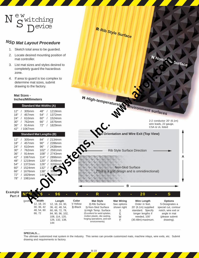
NSD Mat Layout Procedure1. Sketch total area to be guarded.
2. Locate desired mounting position ofmat controller.
3. List mat sizes and styles desired tocompletely guard the hazardouszone.
4. If area to guard is too complex todetermine mat sizes, submitdrawing to the factory.
B-19
Mat Sizes -Inches/Millimeters
Standard Mat Widths (A)
12" / 305mm 48" / 1219mm18" / 457mm 54" / 1372mm24" / 610mm 60" / 1524mm30" / 762mm 66" / 1676mm36" / 914mm 72" / 1829mm42" / 1067mm
Standard Mat Lengths (B)
12" / 305mm 84" / 2134mm18" / 457mm 90" / 2286mm24" / 610mm 96" / 2438mm30" / 762mm 102" / 2591mm36" / 914mm 108" / 2743mm42" / 1067mm 114" / 2896mm48" / 1219mm 120" / 3048mm54" / 1372mm 126" / 3200mm60" / 1524mm 132" / 3353mm66" / 1676mm 138" / 3505mm72" / 1829mm 144" / 3658mm78" / 1981mm
ExamplePart # NSD - 36 - 96 - Y - R - X - 20 - S
(prefix)
SPECIALS....The ultimate customized mat system in the industry. This series can provide customized mats, machine inlays, wire exits, etc. Submitdrawing and requirements to factory.
Width12, 18, 2430, 36, 4248, 54, 6066, 72
Length12, 18, 24, 30,36, 42, 48, 54,60, 66, 72, 78,84, 90, 96, 102,108, 114, 120,126, 132, 138,144
ColorY-YellowB-Black
Mat StyleR-Rib Surface
N-Non-Skid SurfaceH-High Temp. Surface(Excellent for weld splatter,molten plastic, die casting,forging operations, and wet
environments)
Mat WiringSee optionsshown right
XEWP
Wire LengthOrder in feet.
20' (6.1m) suppliedstandard. Specifylonger lengths if
needed, 100’(30.48m) maximum.
OptionsS-Designates a
special cut, contournotch, wire exit or
angle in mat(please submit
drawing).
RRRRR-Rib Style Surface
NNNNN-Non-Skid Surface
Mat Orientation and Wire Exit (Top View)
Rib Style Surface Direction
Non-Skid Surface(This is a grid design and is omnidirectional)
2-2 conductor 20' (6.1m)wire leads, 22 gauge,CSA & UL listed
A
B
N S Dew
witchingevice
HHHHH-High-temperature/wet environment surfaces
Air-O
il Sy
stems,
Inc.
www.a
iroil.co
m
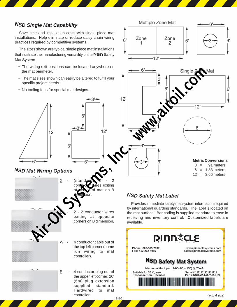
NSD Mat Wiring Options
X - (standard) 2 - 2conductor wires exitingat center of mat on Bdimension.
E - 2 - 2 conductor wiresexiting at oppositecorners on B dimension.
W - 4 conductor cable out ofthe top left corner (homerun wiring to matcontroller).
P - 4 conductor plug out ofthe upper left corner; 20'(6m) plug extensionsupplied standard.Hardwired to matcontroller.
B-20
Metric Conversions 3' = .91 meters 6' = 1.83 meters12' = 3.66 meters
NSD Safety Mat LabelProvides immediate safety mat system information required
by international guarding standards. The label is located onthe mat surface. Bar coding is supplied standard to ease inreceiving and inventory control. Customized labels areavailable.
(actual size)
NSD Single Mat CapabilitySave time and installation costs with single piece mat
installations. Help eliminate or reduce daisy chain wiringpractices required by competitive systems.
The sizes shown are typical single piece mat installationsthat illustrate the manufacturing versatility of the SafetyMat System.
• The wiring exit positions can be located anywhere onthe mat perimeter.
• The mat sizes shown can easily be altered to fulfill yourspecific project needs.
• No tooling fees for special mat designs.
Phone: 800-569-7697Fax: 412-262-4055
Suitable for 35 Kg useResponse Time: 35 msec
Serial # 1111111111111111Part # NSD-72-144-Y-R-X-20
Maximum Mat Input: 24V (AC or DC) @ 75mA
Air-O
il Sy
stems,
Inc.
www.a
iroil.co
m

B-21
Safety mats are required by law to be “fixed” inposition for machine guarding applications.
Chemical ResistenceThe mat housing has excellent resistance to acids, alkalies,
and salts. Hot acids and alkalies, as well as concentratedoxidizing and organic acids, have a deleterious affect overprolonged exposure.
Mat Chemical Resistance
Water E Acetic Acid FEthyl Alcohol E Gasoline FSodium Chloride E ASTM 1 Oil FBleach E Benzene PHydrochloric Acid F to E Aceton PSulfuric Acid F to E Trichlorethylene P to FNitric Acid F to E
Key: E=Excellent; F=Fair; P=Poor
Mat Wiring: Dual 20' (6.1m) 2 conductor, 22 gauge (wiringstyles X and E) and 24 gauge (wiring styles W and P),multistrand wires. CSA & UL Listed.
Mat Cable Diameter: .18" (5mm)
Mat Housing: .25" (6mm) top and bottom mat housing, crossdrain built-in on mat bottom, hermetically sealed, NEMA 6 IP(67)rated. Special mat housings available, consult factory.
Perimeter Trim: Part # M001 High-grade aluminum #6063-T5
Active Coupler: Part # M003D High-grade aluminum #6063-T5
Wire Raceway: Part # M002 High-strength PVC (black)
Mat Temperature Rating: -150C to 550C / 40F to 1300F
Maximum Mat Input: 24V (AC or DC) @ 75 mA
Perimeter Trim for NSD MatsPerimeter Trim (Part #M001) is used for anchoring the outside
perimeter of the safety mat assembly to the floor and to run themat wiring back to a location near the mat controller. The uniquewire raceway is built into theperimeter trim and is suppliedstandard with all Part #M001 orders.The perimeter trim adds 2.5"(64mm) to mat dimension per edge.
Ordering Procedure: Specifylinear feet or dimensions followedby one of the following:
TK: (picture frame trim kit)M001: (bulk)M001-M: (bulk/machined)Custom Trim Kit: (consult factory)
Example: Part # 2442TK.This example is a 24" x 42" mat with a24" x 42" picture frame trim kit; total area is 29" x 47".
Active Coupler (Part #M003D) is used whenever the mats areplaced side to side or end to side. This will activate the “ActiveEdging™” feature which will eliminate dead zones between mats.The active coupler adds .25" (6mm) to mat system’s overalldimension.
Ordering Procedure: Specify Part Number and total lengthrequired in feet.
Built-in Wire Raceway (Part #M002)
This innovative design concept provides excellent wiringprotection for your safety mat system. The design provides anelevated off the floor wire raceway to protect the wiring andconnections from fluids and caustic materials on the floor. It alsoprovides a wiring harness to protect the mat wires from beingpinched by improper perimeter trim installations commonly foundin the industry.
Recessed AreaFor 1” (25mm)
Colored Safety Marking
Perimeter TrimPart #M001
Aluminum Active CouplerPart #M003D
MAMAMAMAMATTTTT
Typical Cross SectionView of Mat Assembly
Built-in Wire RacewayPart # M002
Simple in-house tests foryou to try!!!
1. Stab or puncture with nails,ice pick, etc. approximately tentimes in various areas on themat sensing surface.
2. Bend the mat corners and seewhat happens.
3. Place on uneven floors andcompare.
NSD vs. Steel Electrode Durability Test
Air-O
il Sy
stems,
Inc.
www.a
iroil.co
m

System Overview
The Safety Mat Systemcontrollers contain two independentcontrol circuits which allow for shut downdue to any single failure in one of thecontrol circuits. The N.O. output circuitis controlled by two captive contactrelays in series which are bothmonitored. If the contact in one relayshould stick closed (i.e., contact weld),the other relay will shut down and theLED will indicate the fault; if the contacton the bad relay opens back up, youmust reset the power to clear the fault.This relay contact monitoring provides ahigh degree of user safety.
Circuit DescriptionA low voltage (24VAC or 24VDC)
signal is sent out to the safety mat(s)through two wires. Two special optically-isolated diverse redundant circuits lookat the signals coming back from themat(s) detecting the presence of properpositive and negative voltage (AC) levelsand output their signals to redundantmissing pulse detectors. If the voltagecoming back is too high or low, themissing pulse detectors will drop out andde-energize the relay circuit. If thevoltage coming back is not AC (missingeither positive or negative peaks), thenthe signal going to the missing pulsedetector will disappear which will, in turn,drop out and de-energize the relaycircuit.
Redundant relay position detectorswatch for a relay contact stuck in thewrong position. The circuits will lock outthe reset feature of the control unitif a relay contact is closed when it shouldbe open.
Each relay has its own driver circuit tocomplete the redundancy of the circuits.
Specifications
Enclosure: NEMA 12, 13, IP 54
Input Power: 120VAC +/- 10% @ 3 watts50-60 Hz fused
Category/Type: 4
Relay Style: Monitored force-guided captive contactsafety relays
Relay Configuration: 2 N.O. Safety Relays (closed when
circuit activated)
1 Aux. Output N.O. or N.C
Safety Relay Rating: 4A @ 220VAC
Reset Provisions: Manual or Automatic
Controller Response Time: 15 ms
Self-Checking Intervals: Every 20 ms
Number of Isolated Zones: 1 to 13 (customer specified)
Maximum Number of Mats: 20 with daisy chain wiring
External Reset Provision: Green push button
Indicators:
Internal (on board): Yellow LED = +5VDC power supplyRed LED = Normally dim, brighterwhen mat is stepped on. Cut wiredetected when not lit.Green LED = Relay contact detectedclosed when it should have been openwhen not lit. Must reset power to clear.
External: Red LED = 1 or both relays arede-energized.Green LED = All relays are energized.
Diagnostic Message Display: N/A
DeviceNet: N/A
Warranty: 2 years
Model NSD-TR-01Metal Box Controller
Safety Mat Controllers
B-22
Air-O
il Sy
stems,
Inc.
www.a
iroil.co
m
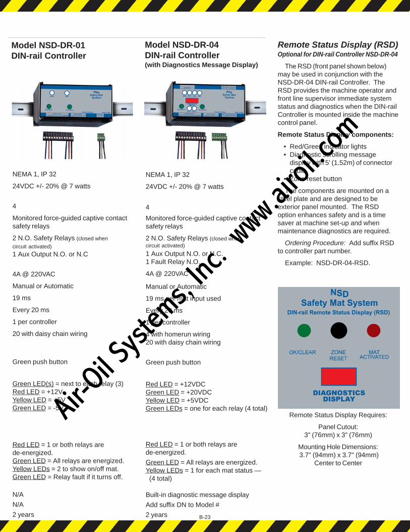
Remote Status Display (RSD)Optional for DIN-rail Controller NSD-DR-04
The RSD (front panel shown below)may be used in conjunction with theNSD-DR-04 DIN-rail Controller. TheRSD provides the machine operator andfront line supervisor immediate systemstatus and diagnostics when the DIN-railController is mounted inside the machinecontrol panel.
Remote Status Display components:
• Red/Green indicator lights• Diagnostic scrolling message
display with 5' (1.52m) of connectorcable
• Zone reset button
The components are mounted on asteel plate and are designed to beexterior panel mounted. The RSDoption enhances safety and is a timesaver at machine set-up and whenmaintenance diagnostics are required.
Ordering Procedure: Add suffix RSDto controller part number.
Example: NSD-DR-04-RSD.
Remote Status Display Requires:
Panel Cutout:3" (76mm) x 3" (76mm)
Mounting Hole Dimensions: 3.7" (94mm) x 3.7" (94mm)
Center to Center
Model NSD-DR-01DIN-rail Controller
Model NSD-DR-04DIN-rail Controller(with Diagnostics Message Display)
NEMA 1, IP 32
24VDC +/- 20% @ 7 watts
4
Monitored force-guided captive contactsafety relays
2 N.O. Safety Relays (closed whencircuit activated)
1 Aux Output N.O. or N.C.1 Fault Relay N.O.
4A @ 220VAC
Manual or Automatic
19 ms per mat input used
Every 20 ms
1 per controller
4 with homerun wiring20 with daisy chain wiring
Green push button
Red LED = +12VDCGreen LED = +20VDCYellow LED = +5VDCGreen LEDs = one for each relay (4 total)
Red LED = 1 or both relays arede-energized.
Green LED = All relays are energized.Yellow LEDs = 1 for each mat status — (4 total)
Built-in diagnostic message display
Add suffix DN to Model #
2 years
NEMA 1, IP 32
24VDC +/- 20% @ 7 watts
4
Monitored force-guided captive contactsafety relays
2 N.O. Safety Relays (closed when
circuit activated)
1 Aux Output N.O. or N.C
4A @ 220VAC
Manual or Automatic
19 ms
Every 20 ms
1 per controller
20 with daisy chain wiring
Green push button
Green LED(s) = next to each relay (3)Red LED = +12VYellow LED = +5VGreen LED = -5V
Red LED = 1 or both relays arede-energized.Green LED = All relays are energized.Yellow LEDs = 2 to show on/off mat.Green LED = Relay fault if it turns off.
N/A
N/A
2 years B-23
Air-O
il Sy
stems,
Inc.
www.a
iroil.co
m
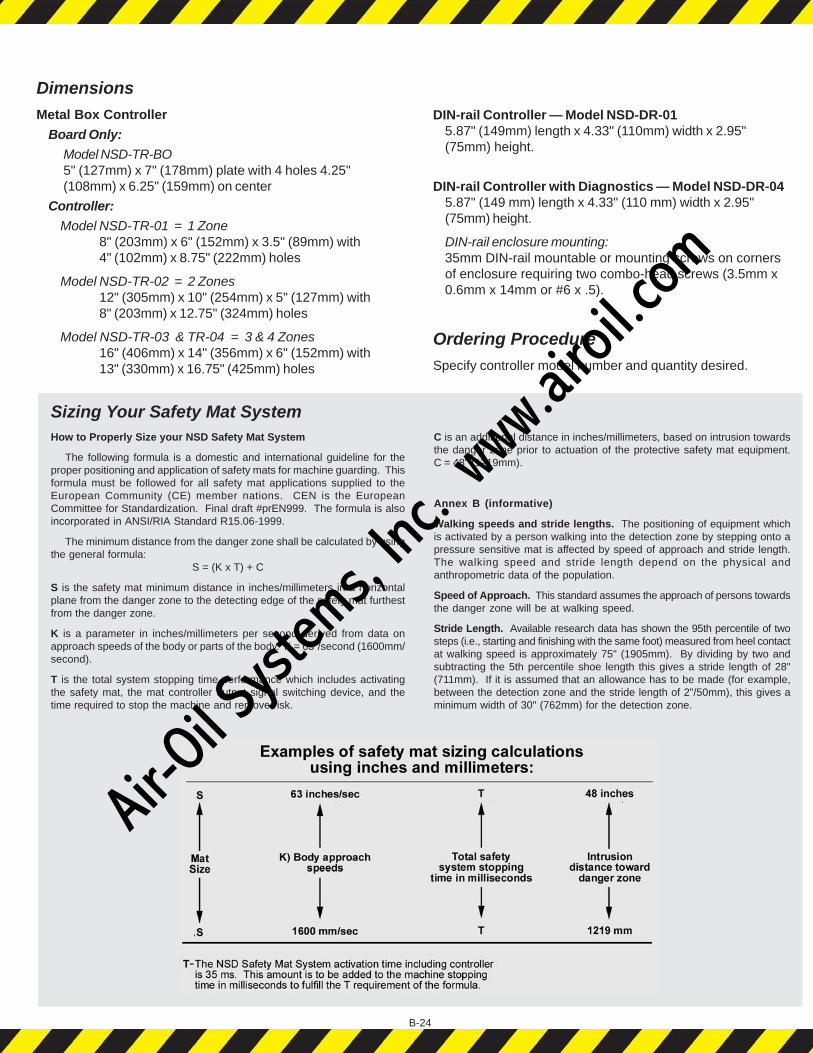
Sizing Your Safety Mat SystemHow to Properly Size your NSD Safety Mat System
The following formula is a domestic and international guideline for theproper positioning and application of safety mats for machine guarding. Thisformula must be followed for all safety mat applications supplied to theEuropean Community (CE) member nations. CEN is the EuropeanCommittee for Standardization. Final draft #prEN999. The formula is alsoincorporated in ANSI/RIA Standard R15.06-1999.
The minimum distance from the danger zone shall be calculated by usingthe general formula:
S = (K x T) + C
S is the safety mat minimum distance in inches/millimeters in a horizontalplane from the danger zone to the detecting edge of the safety mat furthestfrom the danger zone.
K is a parameter in inches/millimeters per second derived from data onapproach speeds of the body or parts of the body. K = 63”/second (1600mm/second).
T is the total system stopping time performance which includes activatingthe safety mat, the mat controller output signal switching device, and thetime required to stop the machine and remove risk.
DimensionsMetal Box Controller
Board Only:
Model NSD-TR-BO5" (127mm) x 7" (178mm) plate with 4 holes 4.25"(108mm) x 6.25" (159mm) on center
Controller:
Model NSD-TR-01 = 1 Zone8" (203mm) x 6" (152mm) x 3.5" (89mm) with4" (102mm) x 8.75" (222mm) holes
Model NSD-TR-02 = 2 Zones12" (305mm) x 10" (254mm) x 5" (127mm) with8" (203mm) x 12.75" (324mm) holes
Model NSD-TR-03 & TR-04 = 3 & 4 Zones16" (406mm) x 14" (356mm) x 6" (152mm) with13" (330mm) x 16.75" (425mm) holes
DIN-rail Controller — Model NSD-DR-015.87" (149mm) length x 4.33" (110mm) width x 2.95"(75mm) height.
DIN-rail Controller with Diagnostics — Model NSD-DR-045.87" (149 mm) length x 4.33" (110 mm) width x 2.95"(75mm) height.
DIN-rail enclosure mounting:35mm DIN-rail mountable or mounting screws on cornersof enclosure requiring two combo-head screws (3.5mm x0.6mm x 14mm or #6 x .5).
Ordering ProcedureSpecify controller model number and quantity desired.
C is an additional distance in inches/millimeters, based on intrusion towardsthe danger zone prior to actuation of the protective safety mat equipment.C = 48" (1219mm).
Annex B (informative)
Walking speeds and stride lengths. The positioning of equipment whichis activated by a person walking into the detection zone by stepping onto apressure sensitive mat is affected by speed of approach and stride length.The walking speed and stride length depend on the physical andanthropometric data of the population.
Speed of Approach. This standard assumes the approach of persons towardsthe danger zone will be at walking speed.
Stride Length. Available research data has shown the 95th percentile of twosteps (i.e., starting and finishing with the same foot) measured from heel contactat walking speed is approximately 75" (1905mm). By dividing by two andsubtracting the 5th percentile shoe length this gives a stride length of 28"(711mm). If it is assumed that an allowance has to be made (for example,between the detection zone and the stride length of 2"/50mm), this gives aminimum width of 30" (762mm) for the detection zone.
B-24
Air-O
il Sy
stems,
Inc.
www.a
iroil.co
m
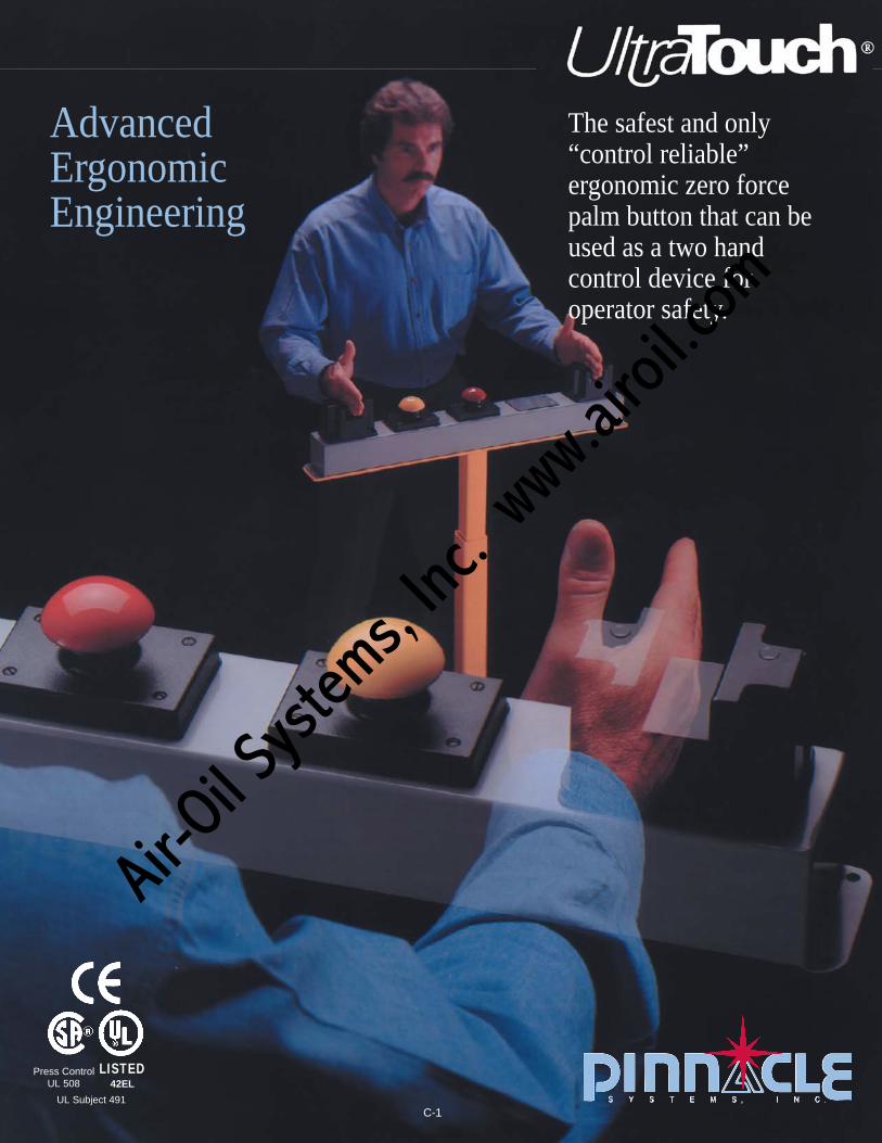
AdvancedErgonomicEngineering
The safest and only“control reliable”ergonomic zero forcepalm button that can beused as a two handcontrol device foroperator safety.
Press ControlUL 508
LISTED42EL
UL Subject 491C-1
Air-O
il Sy
stems,
Inc.
www.a
iroil.co
m

C-2
The Industrial Problem ofCumulative TraumaDisorders (CTDs)and Carpal TunnelSyndrome (CTS)
WhatUltraTouch®
Does For You
BenefitsHuman Factor Engineering (Ergonomics)UltraTouch® has been designed to interact with theoperator, machine operation, and the work place in a safeand efficient way. This effective design of equipment willbe most helpful in the controlling of Carpal TunnelSyndrome and other Cumulative Trauma Disorders.
Productivity IncreasesIncreases in productivity are achieved by a reduction inoperator fatigue and operator injury along with basicproduction line cycle time decreases.
Employee MoraleEasier job related actions and movements with both workmethods analysis and ergonomic checklist analysisprovide a healthier and more positive work environment.
Fatigue ControlEase of safe machine activation enables the machine
operators to utilize their energy for more productiveefforts. The reduction of fatigue is an essential elementwhen trying to control Cumulative Trauma Disorderssuch as Carpal Tunnel Syndrome.
The patented soundergonomic design criteria ofUltraTouch® advances machinecycle initiation into the 21stcentury. The UltraTouchsystem has been designed so themachine operator can initiatethe machine cycle with theirhand and wrist area in theneutral position and with noexertion of force or pressure.
This minimizes hand,wrist, and arm stresses relatedto the potentially harmfulextension and flexion positionsof the hand required to activateconventional spring-loadedpalm buttons. No flexing ofthe wrist is necessary withUltraTouch.
Wrist and hand positionsare most important as contrib-uting elements of CarpalTunnel Syndrome. Wristposition is important because itaffects the length and tensionrelationship of contractingmuscles. As the angle of thejoint (wrist) increases ordecreases beyond its midpoint(neutral position), there is aproportional decrease in themachine operators effectivestrength. This means thatmore exertion or tendon tensionis required to do a task with abent wrist than the same taskwith the wrist in the neutralposition. Hand and wristposture along with forcerequired are base contributingelements to Carpal TunnelSyndrome.
PalmarSide
DorsalSide
Median Nerve
Red shaded areas normally affected by symptons of carpal tunnel syndrome,which include tingling or burning sensation, clumsiness, hand pain andnumbness.
What are Cumulative Trauma Disorders (CTDs)?Cumulative Trauma Disorders (CTDs) is the mostcommon term used to refer to the diseases related to theupper limbs. Similar terms used to describe these problemareas are:
• repetitive strain injuries• occupational cervicobrachial disorders• occupational overuse syndromes
Cumulative Trauma Disorders are caused by repetitivestresses on a particular body part after periods of jobrelated micro-trauma. Basically there are three types ofinjuries to the machine operator. These injuries includenerve disorders, tendon disorders or neuro-vasculardisorders.
Nerve Disorders-Carpal Tunnel Syndrome (CTS)
Common Tendon Disorders-Tendinitis, Tenosynovitis,DeQuervain's disease, Stenosing Tendsynovitas, StenosingTenosynovitas Crepitans.
Neurovascular Disorders-Thoracic outlet syndrome.
Air-O
il Sy
stems,
Inc.
www.a
iroil.co
m
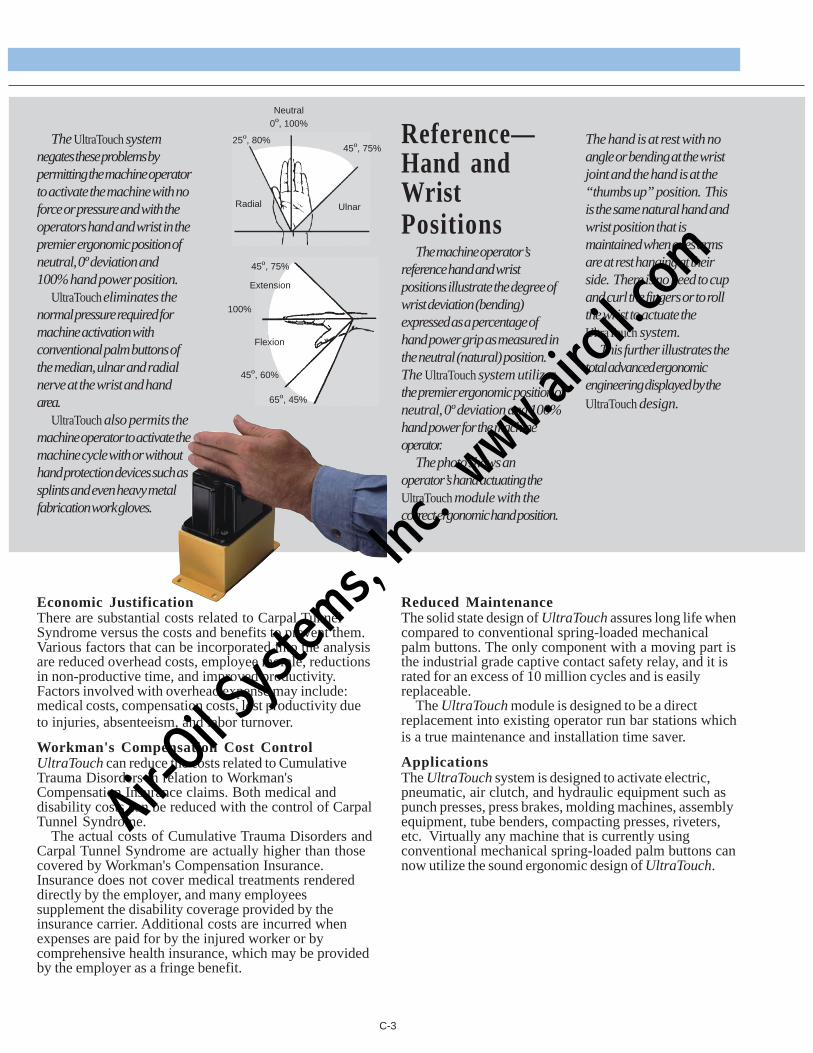
C-3
Economic JustificationThere are substantial costs related to Carpal TunnelSyndrome versus the costs and benefits to prevent them.Various factors that can be incorporated into the analysisare reduced overhead costs, employee morale, reductionsin non-productive time, and improved productivity.Factors involved with overhead expense may include:medical costs, compensation costs, lost productivity dueto injuries, absenteeism, and labor turnover.
Workman's Compensation Cost ControlUltraTouch can reduce the costs related to CumulativeTrauma Disorders in relation to Workman'sCompensation Insurance claims. Both medical anddisability costs can be reduced with the control of CarpalTunnel Syndrome.
The actual costs of Cumulative Trauma Disorders andCarpal Tunnel Syndrome are actually higher than thosecovered by Workman's Compensation Insurance.Insurance does not cover medical treatments rendereddirectly by the employer, and many employeessupplement the disability coverage provided by theinsurance carrier. Additional costs are incurred whenexpenses are paid for by the injured worker or bycomprehensive health insurance, which may be providedby the employer as a fringe benefit.
Reduced MaintenanceThe solid state design of UltraTouch assures long life whencompared to conventional spring-loaded mechanicalpalm buttons. The only component with a moving part isthe industrial grade captive contact safety relay, and it israted for an excess of 10 million cycles and is easilyreplaceable.
The UltraTouch module is designed to be a directreplacement into existing operator run bar stations whichis a true maintenance and installation time saver.
ApplicationsThe UltraTouch system is designed to activate electric,pneumatic, air clutch, and hydraulic equipment such aspunch presses, press brakes, molding machines, assemblyequipment, tube benders, compacting presses, riveters,etc. Virtually any machine that is currently usingconventional mechanical spring-loaded palm buttons cannow utilize the sound ergonomic design of UltraTouch.
Reference—Hand andWristPositions
The machine operator’sreference hand and wristpositions illustrate the degree ofwrist deviation (bending)expressed as a percentage ofhand power grip as measured inthe neutral (natural) position.The UltraTouch system utilizesthe premier ergonomic position ofneutral, 0º deviation and 100%hand power for the machineoperator.
The photo shows anoperator’s hand actuating theUltraTouch module with thecorrect ergonomic hand position.
The hand is at rest with noangle or bending at the wristjoint and the hand is at the“thumbs up” position. Thisis the same natural hand andwrist position that ismaintained when ones armsare at rest hanging at theirside. There is no need to cupand curl the fingers or to rollthe wrist to actuate theUltraTouch system.
This further illustrates thetotal advanced ergonomicengineering displayed by theUltraTouch design.
The UltraTouch systemnegates these problems bypermitting the machine operatorto activate the machine with noforce or pressure and with theoperators hand and wrist in thepremier ergonomic position ofneutral, 0º deviation and100% hand power position.
UltraTouch eliminates thenormal pressure required formachine activation withconventional palm buttons ofthe median, ulnar and radialnerve at the wrist and handarea.
UltraTouch also permits themachine operator to activate themachine cycle with or withouthand protection devices such assplints and even heavy metalfabrication work gloves.
Neutral0º, 100%
25º, 80%45º, 75%
Radial Ulnar
Extension
Flexion
45º, 75%
100%
45º, 60%
65º, 45%
Air-O
il Sy
stems,
Inc.
www.a
iroil.co
m

C-4
SensorsActuationTunnel
InfraredBeam Sensor
Patented—U.S. Patent and Trademark Office
UltraTouch® DesignThe patented UltraTouch® system has been designed asa direct replacement for standard spring-loadedmechanical palm buttons and is designed to fit intoexisting operator palm button stations withoutmodification.
The UltraTouch enclosure is a molded high strengthNEMA 4 polycarbonate module designed to meet thehigh impact and vibration requirements of industry. Thesolid state electronics of the UltraTouch switchincorporates an advanced redundant diverse sensordesign. This means that each module has two differentsensors with isolated circuits along with a monitoringredundant circuit. The circuitry of UltraTouch is alsodesigned to provide second-order failure protection. Thisgives the UltraTouch an unparalleled level of safety andassurance against inadvertent actuation, or failing in the"on" or conducting mode, which is a common problemfound throughout industry with competitive ergonomicswitch replacements. The UltraTouch design is so safeagainst inadvertent actuation that two UltraTouch moduleswhen spaced and located properly in accordance toOSHA and ANSI hand control distance formulas (the
same formula is used for mechanical palm buttons),permit its use as an operator safety two-hand controldevice. The UltraTouch dual dissimilar sensor format isdesigned for the machine operator to actuate the switch,and that no inadvertent foreign objects such as sleeves,insects, broomsticks, playing cards, rags, mists or dropletscan activate or trigger the switch. This gives UltaTouch anunparalleled level of safety while giving the operator thebenefit of using the correct ergonomic hand position ofneutral, 0º deviation and 100% hand power.
UltraTouch ConfigurationThe UltraTouch dual dissimilar sensor ergonomic palmswitch is configured in the following manner:
A U-shaped sensors actuation channel (shown below)provides a triggering point for the machine operatorshand. This is where the invisible infrared light beam islocated and is crossing the channel. There is also a uniqueU-shaped location sensor mounted on the inside of theUltraTouch enclosure that hugs the sensor channel and isinsulated by the enclosure itself. When the machineoperator inserts their hand into the sensor actuationtunnel, both the infrared sensor and the location sensormust be satisfied in order to energize an electro-
Module
(Actual Size, Top View)
NEMA 4Sealed Housing
GreenStatusIndicator
Location,Sensor Field
RedStatusIndicator
MountingHoles (4)
Press ControlUL 508
LISTED42EL
UL Subject 491
(continued)
Air-O
il Sy
stems,
Inc.
www.a
iroil.co
m

C-5
mechanical relay to send a cycle start signal to themachine. Both individual sensors within each moduleare time interlocked, and if both sensors are nottriggered concurrently by the operator’s hand, theUltraTouch output will be inhibited to the machinecontrol. The module also contains two visible LEDindicators which informs the status of the UltraTouchmodule to the operator. A green LED indicates that therelay contacts are closed, both sensors have beenactivated, and no failures have been detected. The redLED indicates that the relay contacts are open and nosatisfactory conditions were detected on both sensors.This advanced patented UltraTouch design is notavailable on any competitive unit and gives theUltraTouch user an unparalleled level of safety whenusing ergonomic zero force actuation devices.Additionally, the operator will be activating themachine properly by using the correct ergonomic handposition of neutral, 0º deviation, and 100% handpower.
Easy to InstallUltraTouch installs with ease and comes with complete
installation instructions.Simple module design permits direct exchange for
existing spring-loaded mechanical palm buttons and evenutilizes the existing screw holes on the run bar. All systemshave normally open (N.O.) and normally closed (N.C.)contacts, and are also available in a four pole wiringconfiguration depending on the machine controlrequirements. The ultimate in versatility!
New installations and retrofit projects are completely
installed in minutes by a qualified electrician. Alsosupplied is a toll free 800 number if any questions shouldarise by your installation personnel.
UltraSafe DesignEach UltraTouch switch module incorporates the
following safety design features:• Two dissimilar sensors
a) Infrared sensorb) Positive location sensor
• Redundant circuitry• Chatterfree design circuit• Anti-noise circuit• No false trip on power up circuit• Captive contact safety relays• Operator status indicators• Interlock circuit between the diverse sensors• Immune to EMI and RFI noise• Immune to weld field interference• Control reliable design
OSHA, ANSI & CSA StandardsThe mounting locations of UltraTouch must conform to
all State, Province, and Federal codes and all regulationspertaining to the subject machine on which the UltraTouchis to be applied.
Point of Operation GuardingThe UltraTouch system is a machine cycle initiation
component that is designed to be a two-hand controldevice for the machine operator. If a point of operationguarding device is desired or required, please contact yourlocal distributor or the factory for devices to comply withANSI B11.1 or the various OSHA regulations.
American National Standard B11.19-19904.2.4.2.3 Two-Hand Control Devices. The two-hand control shall be designed to
protect each hand control against accidental or unintentional operation.The two-hand control shall have the individual operator's hand controls arranged by
design, construction, or separation to require the use of both hands to cycle the machine tool.The two-hand control shall be designed to require concurrent operation of both the
operator's hand controls to cycle the machine tool.If more than one operator is to be safeguarded by the use of two-hand controls, each
operator shall have individual operator hand controls. The selection of the operator's controlsshall be capable of being supervised by the employer. Additionally, each selected two-handcontrol shall be concurrently operated before the machine tool is cycled. The two-hand controlsystem shall be designed and constructed so as to prevent cycling of the machine tool if all theoperator's stations are deselected.
The two-hand control shall be designed to require the release of all selected operator'shand controls and the reactuation of all operator's controls before a machine cycle can beinitiated.
4.2.4.3 Operation4.2.4.3.1 It shall be the responsibility of the employer to ensure that the two-hand
operating lever, trip, or control device is installed, operated, and maintained in accordance withthis standard.
4.2.4.3.2 The device shall be located at a distance from the nearest hazard suchthat the operator cannot reach the hazard with a hand or other body part before cessation ofmotion of the hazardous portion of the machine cycle. The two-hand operating lever, trip, orcontrol device shall require concurrent actuation of both of the operating levers or hand controlsto initiate a machine cycle.
4.2.4.3.3 The two-hand control device shall require the concurrent actuation of theoperator's hand controls during the hazardous portion of the machine cycle such that theoperator cannot reach the hazard before the hazardous motion has ceased.
OSHA Federal Register Section 1910.217(v) Two-hand controls for single stroke shall conform to the following requirements:(a) Each hand control shall be protected against unintended operation and arranged by
design, construction, and/or separation so that the concurrent use of both hands is required totrip the press.
(b) The control system shall be designed to permit an adjustment which will requireconcurrent pressure from both hands during the die closing portion of the stroke.
(c) The control system shall incorporate an anti-repeat feature.(d) The control system shall be designed to require release of all operators' hand controls
before an interrupted stroke can be resumed. This requirement pertains only to those single-stroke, two-hand controls manufactured and installed on or after August 31, 1971.
* * * * *(vii) The two-hand control device shall protect the operator as specified in paragraph
(c)(3)(i)(e) of Section 1910.217.(a) When used in press operations requiring more than one operator, separate two-hand
controls shall be provided for each operator, and shall be designed to require concurrentapplication of all operators' controls to activate the slide. The removal of a hand from any controlbutton shall cause the slide to stop.
(b) Each two-hand control shall meet the construction requirements of paragraph (b)(7)(v)of this section.
(c) The safety distance (Ds) between each two-hand control device and the point ofoperation shall be greater than the distance determined by the following formula:
Ds=63 inches/second X Ts;where: Ds = minimum safety distance (inches); 63 inches/second-hand speed constant;and Ts = stopping time of the press measured at approximately 90º position of crankshaft
rotation (seconds).(d) Two-hand controls shall be fixed in position so that only a supervisor or safety
engineer is capable of relocating the controls.
(Below standards are only partial reprint)
Air-O
il Sy
stems,
Inc.
www.a
iroil.co
m

Ergonomic Palm Button Replacement Grid Checklist
“Compare the Difference” UltraTouch
* Requires two UltraTouch modules spaced and mounted in accordance with current OSHA and ANSI standards. OSHA andANSI standards also require machines to have “control reliable” control circuitry.
C-6
YES ________ ________
YES ________ ________
YES ________ ________
YES ________ ________
YES ________ ________
YES ________ ________
YES ________ ________
YES ________ ________
YES ________ ________
YES ________ ________
YES ________ ________
YES ________ ________
YES ________ ________
YES ________ ________
YES ________ ________
YES ________ ________
YES ________ ________
YES ________ ________
YES ________ ________
YES ________ ________
YES ________ ________
YES ________ ________
YES ________ ________
YES ________ ________
YES ________ ________
YES ________ ________
YES ________ ________
YES ________ ________
YES ________ ________
YES ________ ________
YES ________ ________
• Diverse dual sensor design
• Control reliable design of sensor circuits
• Redundant circuitry
• Incorporates second-order circuit failure protection
• Internal self-checking of infrared sensor and system circuits
• Built-in timed interlock within each module for the two diversesensors
• Utilizes captive contact safety relays
• Diagnostics of sensor circuits and diverse sensors interlock circuit
• Not affected by external infrared light sources
• Built-in hysteresis
• No false trip on power up
• Anti-noise circuitry built-in
• Chatter free design built in
• Weld field immune
• EMI and RFI immune
• Completely self-contained unit, requires no additional relays orinterface boards
• Operator status indicator lights– A. Red – Ready to cycleB. Green – Cycle initiated
• Fast reacting–Less than 20 ms
• NEMA 4 enclosure
• Designs available for all machines:110 VAC – 2 pole or 4 pole configuration24 VDC – 2 pole or 4 pole configuration
• Directly interchangeable with existing mechanical palm buttons:A. ElectricallyB. Mechanically
• Requires correct ergonomic hand position for zero force machineactuation of neutral, 0º deviation, and 100% hand power
• Cannot be actuated by screwdrivers, playing cards, rags, sleeves,broomsticks, mists or droplets
• Tactile feedback feel requires the operator to have the proper handlocation for both safety and ergonomics
• Cannot be actuated by the operator’s elbows
• Can be used as an operator two-hand safety control device*
• Complies with all applicable sections of OSHA, ANSI and CSAstandards for operator two-hand control devices
• Repairable unit–not a disposable design
• Captive screws and gaskets supplied to ease installation
• Two-year warranty
• Made in USA
DesignCriteria
Press ControlUL 508
LISTED42EL
UL Subject 491
Air-O
il Sy
stems,
Inc.
www.a
iroil.co
m
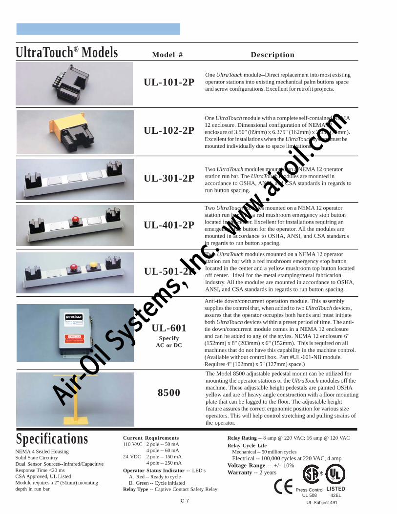
UltraTouch® Models Model # Description
UL-101-2P
UL-102-2P
UL-301-2P
UL-401-2P
UL-501-2P
UL-601Specify
AC or DC
8500
Two UltraTouch modules mounted on a NEMA 12 operatorstation run bar. The UltraTouch modules are mounted inaccordance to OSHA, ANSI, and CSA standards in regards torun button spacing.
Two UltraTouch modules mounted on a NEMA 12 operatorstation run bar with a red mushroom emergency stop buttonlocated in the center. Excellent for installations requiring anemergency stop button for the operator. All the modules aremounted in accordance to OSHA, ANSI, and CSA standardsin regards to run button spacing.
Two UltraTouch modules mounted on a NEMA 12 operatorstation run bar with a red mushroom emergency stop buttonlocated in the center and a yellow mushroom top button locatedoff center. Ideal for the metal stamping/metal fabricationindustry. All the modules are mounted in accordance to OSHA,ANSI, and CSA standards in regards to run button spacing.
Anti-tie down/concurrent operation module. This assemblysupplies the control that, when added to two UltraTouch devices,assures that the operator occupies both hands and must initiateboth UltraTouch devices within a preset period of time. The anti-tie down/concurrent module comes in a NEMA 12 enclosureand can be added to any of the styles. NEMA 12 enclosure 6"(152mm) x 8" (203mm) x 6" (152mm). This is required on allmachines that do not have this capability in the machine control.(Available without control box. Part #UL-601-NB module.Requires 4" (102mm) x 5" (127mm) space.)
One UltraTouch module with a complete self-contained NEMA12 enclosure. Dimensional configuration of NEMA 12enclosure of 3.50" (89mm) x 6.375" (162mm) x 2.95" (75mm).Excellent for installations when the UltraTouch system must bemounted individually due to space limitations.
The Model 8500 adjustable pedestal mount can be utilized formounting the operator stations or the UltraTouch modules off themachine. These adjustable height pedestals are painted OSHAyellow and are of heavy angle construction with a floor mountingplate that can be lagged to the floor. The adjustable heightfeature assures the correct ergonomic position for various sizeoperators. This will help control stretching and pulling strains ofthe operator.
C-7
One UltraTouch module--Direct replacement into most existingoperator stations into existing mechanical palm buttons spaceand screw configurations. Excellent for retrofit projects.
SpecificationsNEMA 4 Sealed HousingSolid State CircuitryDual Sensor Sources--Infrared/CapacitiveResponse Time <20 msCSA Approved, UL ListedModule requires a 2" (51mm) mountingdepth in run bar
Current Requirements110 VAC 2 pole -- 50 mA
4 pole -- 60 mA24 VDC 2 pole -- 150 mA
4 pole -- 250 mA
Operator Status Indicator -- LED'sA. Red -- Ready to cycleB. Green -- Cycle initiated
Relay Type -- Captive Contact Safety Relay
Relay Rating -- 8 amp @ 220 VAC; 16 amp @ 120 VAC
Relay Cycle LifeMechanical -- 50 million cyclesElectrical -- 100,000 cycles at 220 VAC, 4 amp
Voltage Range -- +/- 10%Warranty -- 2 years
Press ControlUL 508
LISTED42EL
UL Subject 491
Air-O
il Sy
stems,
Inc.
www.a
iroil.co
m
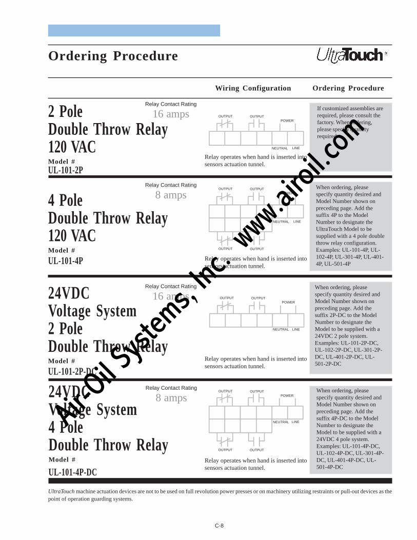
Ordering Procedure
Wiring Configuration Ordering Procedure
2 PoleDouble Throw Relay120 VACModel #UL-101-2P
4 PoleDouble Throw Relay120 VACModel #
UL-101-4P
24VDCVoltage System2 PoleDouble Throw RelayModel #
UL-101-2P-DC
24VDCVoltage System4 PoleDouble Throw RelayModel #
UL-101-4P-DC
UltraTouch machine actuation devices are not to be used on full revolution power presses or on machinery utilizing restraints or pull-out devices as thepoint of operation guarding systems.
C-8
Relay Contact Rating
16 amps
Relay Contact Rating
8 amps
Relay Contact Rating
16 amps
Relay Contact Rating
8 amps
When ordering, pleasespecify quantity desired andModel Number shown onpreceding page. Add thesuffix 4P to the ModelNumber to designate theUltraTouch Model to besupplied with a 4 pole doublethrow relay configuration.Examples: UL-101-4P, UL-102-4P, UL-301-4P, UL-401-4P, UL-501-4P
When ordering, pleasespecify quantity desired andModel Number shown onpreceding page. Add thesuffix 2P-DC to the ModelNumber to designate theModel to be supplied with a24VDC 2 pole system.Examples: UL-101-2P-DC,UL-102-2P-DC, UL-301-2P-DC, UL-401-2P-DC, UL-501-2P-DC
If customized assemblies arerequired, please consult thefactory. When ordering,please specify quantityrequired.
When ordering, pleasespecify quantity desired andModel Number shown onpreceding page. Add thesuffix 4P-DC to the ModelNumber to designate theModel to be supplied with a24VDC 4 pole system.Examples: UL-101-4P-DC,UL-102-4P-DC, UL-301-4P-DC, UL-401-4P-DC, UL-501-4P-DC
Relay operates when hand is inserted intosensors actuation tunnel.
Relay operates when hand is inserted intosensors actuation tunnel.
Relay operates when hand is inserted intosensors actuation tunnel.
Relay operates when hand is inserted intosensors actuation tunnel.
OUTPUT OUTPUTPOWER
NEUTRAL LINE
OUTPUT OUTPUTPOWER
NEUTRAL LINE
OUTPUT OUTPUT
OUTPUT OUTPUTPOWER
NEUTRAL LINE
OUTPUT OUTPUTPOWER
NEUTRAL LINE
OUTPUT OUTPUT
Air-O
il Sy
stems,
Inc.
www.a
iroil.co
m
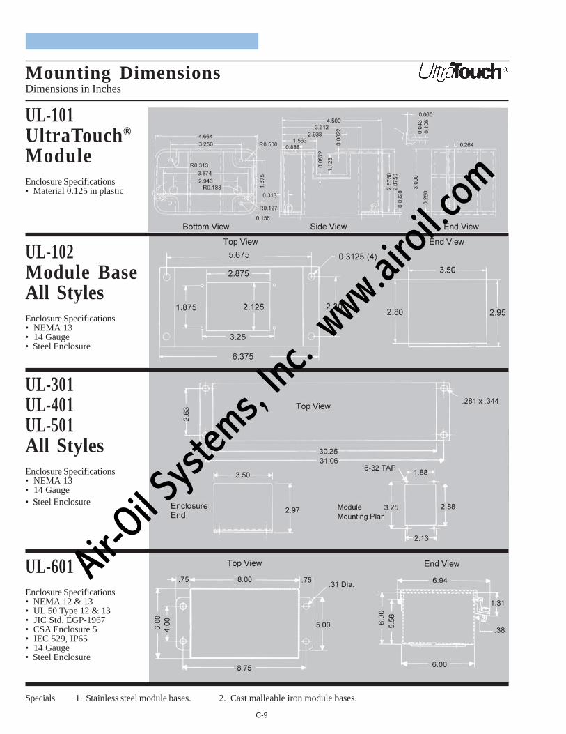
UL-101UltraTouch®
ModuleEnclosure Specifications• Material 0.125 in plastic
UL-102Module BaseAll StylesEnclosure Specifications• NEMA 13• 14 Gauge• Steel Enclosure
C-9
Specials 1. Stainless steel module bases. 2. Cast malleable iron module bases.
UL-301UL-401UL-501All StylesEnclosure Specifications• NEMA 13• 14 Gauge• Steel Enclosure
UL-601Enclosure Specifications• NEMA 12 & 13• UL 50 Type 12 & 13• JIC Std. EGP-1967• CSA Enclosure 5• IEC 529, IP65• 14 Gauge• Steel Enclosure
Mounting DimensionsDimensions in Inches
Air-O
il Sy
stems,
Inc.
www.a
iroil.co
m

Occupational Safety and HealthAdministration (OSHA)
29 CFR Part 1910 Subpart OMachinery and Machine Guarding
1910.211 - Definitions.1910.212 - General requirements for all machines.1910.213 - Woodworking machinery requirements.1910.214 - Cooperage machinery. [Reserved]1910.215 - Abrasive wheel machinery.1910.216 - Mills and calenders in the rubber and plastics
industries.1910.217 - Mechanical power presses.1910.217 - (Appendix A) Mandatory requirements for
certification/validation of safety systems forpresence sensing device initiation ofmechanical power presses
1910.217 - (Appendix B) Nonmandatory guidelines forcertification/validation of safety systems forpresence sensing device initiation ofmechanical power presses
1910.217 - (Appendix C) Mandatory requirements forOSHA recognition of third-party validationorganizations for the PSDI standard
1910.217 - (Appendix D) Nonmandatory supplementaryinformation
1910.218 - Forging machines.1910.219 - Mechanical power-transmission apparatus.
American National Standards Institute(ANSI)ANSI B11 TR1-1993 Ergonomic Guidelines for theDesign, Installation and Use of Machine Tools (NOT ANAMERICAN NATIONAL STANDARD)ANSI B11 TR2-1997 Mist Control Considerations for theDesign, Installation and Use of Machine ToolsMetalworking FluidsANSI B11 TR3-2000 Risk Assessment and RiskReduction - A Guide to Estimate, Evaluate and ReduceRisks Associated with Machine ToolsANSI B11.1-1988 Machine Tools - Mechanical PowerPresses - Safety Requirements for Construction, Care,and UseANSI B11.2-1995 (R2000) Machine Tools - HydraulicPower Presses, Safety Requirements for Construction,Care, and UseANSI B11.3-1982 (R1994) Power Press Brakes, SafetyRequirements for the Construction, Care, and Use ofANSI B11.4-1993 Machine Tools - Shears - SafetyRequirements for Construction, Care, and UseANSI B11.5-1988 (R1994) Machine Tools - Iron Workers -Safety Requirements for Construction, Care, and Use
Safety Codes and Standards
ANSI B11.6-1984 (R1994) Lathes, Safety Requirementsfor the Construction, Care, and Use ofANSI B11.7-1995 Machine Tools - Cold Headers andCold Formers, Safety Requirements for Construction,Care, and UseANSI B11.8-1983 (R1994) Drilling, Milling, and BoringMachines, Safety Requirements for the Construction,Care, and Use ofANSI B11.9-1975 (R1997) Grinding Machines, SafetyRequirements for the Construction, Care, and Use ofANSI B11.10-1990 Metal Sawing Machines, SafetyRequirements for Construction, Care, and Use ofANSI B11.11-1985 Gear Cutting Machines, SafetyRequirements for the Construction, Care, and Use ofANSI B11.12-1996 Machine Tools - Roll-Forming andRoll-Bending Machines - Safety Requirements for theConstruction, Care, and UseANSI B11.13-1992 (R1998) Machine Tools - Single- andMultiple-Spindle Automatic Bar and Chucking Machines -Safety Requirements for Construction, Care and UseANSI B11.14-1996 Machine Tools - Coil-Slitting MachinesSafety Reqirements for Construction, Care, and UseANSI B11.15-1984 (R1994) Pipe, Tube, and ShapeBending Machines, Safety Requirements for Construction,Care, and UseANSI B11.16-1988 Metal Powder Compacting Presses,Safety Requirements for Construction, Care, and UseAdministratively Withdrawn 7/28/2000ANSI B11.17-1996 Machine Tools - Horizontal HydraulicExtrusion Presses,- Safety Requirements for Construction,Care, and UseANSI B11.18-1997 Machine Tools - Machines andMachinery Systems for Processing Strip, Sheet, or Platefrom Coiled Configuration - Safety Requirements forConstruction, Care, and UseANSI B11.19-1990 (R1997) Performance Criteria for theDesign, Construction, Care, and Operation ofSafeguarding When Referenced by the Other B11Machine Tool Safety StandardsANSI B11.20-1991 (R1997) Machine Tools -Manufacturing Systems/Cells - Safety Requirements forConstruction, Care, and UseANSI B11.21-1997 Machine Tools - Machine Tools UsingLasers for Processing Materials - Safety Requirements forDesign, Construction, Care, and UseANSI/RIA R15.06-1999 Industrial Robots and RobotSystems - Safety Requirements
D-1
Air-O
il Sy
stems,
Inc.
www.a
iroil.co
m

Domestic and International Standards’ Organizations
American National Standards Institute (ANSI)25 West 43rd Street, 4th FloorNew York, NY 10036PHONE (Domestic): (212) 642-4900PHONE (Foreign/International): (212) 642-4995FAX: (212) 398-0023WEBSITE: www.ansi.org
Association for Manufacturing Technology (AMT)7901 Westpark DriveMcLean, VA 22101-4269PHONE: (703) 893-2900FAX: (703) 893-1151WEBSITE: www.mfgtech.org
ASME InternationalThree Park AvenueNew York, NY 10016-5990PHONE: (800) 843-2763 (U.S/Canada)
(95) (800) 843-2763 (Mexico)(973) 882-1167 (outside North America)
FAX: (212) 591-7674WEBSITE: www.asme.org
American Society for Nondestructive Testing (ASNT)1711 Arlingate LaneColumbus, OH 43228-0518PHONE: (800) 222-2768 or (614) 274-6003FAX: (614) 274-6899WEBSITE: www.asnt.org
American Society for Testing and Materials (ASTM)100 Barr Harbor DriveWest Conshohocken, PA 19428-2959PHONE: (610) 832-9500FAX: (610) 832-9555WEBSITE: www.astm.org
British Standards Institution (BSI)389 Chiswick High RoadLondonW4 4ALUnited KingdomPHONE: +44 (0)20 8996 9000FAX: +44 (0)20 8996 7400WEBSITE: www.bsi-global.com
Institute for Reference Materials and Measurements(IRRM)European Commission Joint Research CentreInstitute for Reference Materials and MeasurementsRetieseweg, B-2440 Geel, BelgiumPHONE: 32(0)14 571-272FAX: 32(0)14 584-273WEBSITE: www.irmm.jrc.be
Bureau Veritas Quality International (North America)509 North Main StreetJamestown, New York 14701PHONE: (716) 484-9002FAX: (716) 484-9003WEBSITE: www.bvqi.com
Canadian Standards Association (CSA)178 Rexdale BoulevardToronto, OntarioM9W 1R3 CANADAPHONE: (416) 747-4000 or (800) 463-6727FAX: (416) 747-4149WEBSITE: www.csa-international.org
Comite' Europeen de Normalisation (CEN)36, rue de StassartB-1050 BrusselsPHONE: 32 2 550 08 11FAX: 32 2 550 08 19WEBSITE: www.cenorm.be
Comite' Europeen de Normalisation Electrotechnique(CENELEC)Rue de Stassart, 35B-1050 Brussels, BelgiumPHONE: (32) 2-519-6871FAX: (32) 2-519-6919WEBSITE: www.cenelec.org
Electronic Industries Alliance2500 Wilson BoulevardArlington, VA 22201PHONE: (703) 907-7500FAX: (703) 907-7501WEBSITE: www.eia.org
European Community Standards (EN)Available from CEN, CENELEC, ANSI, and from GlobalEngineering Documents.
European Strategic Program for Research and Devel-opment in Information Technology (ESPRIT)2300 M Street, NW, 3rd FloorWashington, D.C. 20037PHONE: (202) 862-9500FAX: (202) 492-1766WEBSITE: www.eurunion.org
Global Engineering Documents15 Ienveress Way EastEnglewood, CO 80112PHONE: (800) 854-7179 or (303) 397-2695FAX: (303) 397-2740WEBSITE: www.global.ihs.com
D-2
Air-O
il Sy
stems,
Inc.
www.a
iroil.co
m

Domestic and International Standards’ Organizations (Cont.)
Institute of Electrical and Electronic Engineers, Inc.(IEE)3 Park Avenue, 17th FloorNew York, NY 10016-5997PHONE: (212) 419-7900FAX: (212) 752-4929WEBSITE: www.ieee.org
Institute of Environmental Sciences and Technology(IEST)940 East Northwest HighwayMount Prospect, Illinois 60056PHONE: (847) 255-1561FAX: (847) 255-1699WEBSITE: www.iest.org
Instrument Society of America (ISA)67 Alexander DriveResearch Triangle Park, NC 27709PHONE: (919) 549-8411FAX: (919) 549-8288WEBSITE: www.isa.org
International Electrochemical Commission (IEC)3, rue de Varembre'P.O. Box 131CH-1211 Geneva 20SwitzerlandPHONE: (41) 22-919-0211FAX: (41) 22-919-0300WEBSITE: www.iec.ch
International Organization for Standardization (ISO)1, rue de Varembe'Case Postale 56CH-1211 Geneva 20SwitzerlandPHONE: (41) 22-749-0111FAX: (41) 22-733-3430WEBSITE: www.iso.ch
Manufacturers Standardization Society of theValve and Fitting Industry (MSS)127 Park Street, NEVienna, VA 22180PHONE: (703) 281-6613FAX: (703) 281-6671WEBSITE: www.mss-hq.com
National Conference of Standards Laboratories(NCSL)1800 30th Street, Suite 305BBoulder, Colorado 80301PHONE: (303) 440-3339FAX: (303) 440-3384WEBSITE: www.ncslinternational.org
National Electrical Manufacturers Association (NEMA)1300 North 17th StreetSuite 1847Rosslyn, VA 22209PHONE: (703) 841-3200FAX: (703) 841-5900WEBSITE: www.nema.org
National Fire Protection Association (NFPA)1 Batterymarch ParkP.O. Box 9101Quincy, MA 02269-9101PHONE: (800) 344-3555FAX: (617) 770-0700WEBSITE: www.nfpa.org
National Institute of Standards and Technology (NIST)US Department of CommerceSemiconductor Electronics DivisionBldg. 225, Room B344Gaithersburg, MD 20899PHONE: (301) 975-2054FAX: (301) 926-1630WEBSITE: www.nist.gov
National Safety Council (NSC)1121 Spring Lake DriveItasca, IL 60143-3201PHONE: (630) 285-1121FAX: (630) 628-1315WEBSITE: www.nsc.org
Occupational Safety & Health Administration (OSHA)United States Inquiries:U.S. Department of LaborOffice of Public Affairs - Room N3647200 Constitution AvenueWashington, D.C. 20210PHONE: (202) 693-1999
International Inquiries:Jacquelyn DeMesme-GrayOSHA Coordinator for International AffairsU.S. Department of LaborOccupational Safety & Health AdministrationDivision of International Affairs - Room N3641200 Constitution AvenueWashington, D.C. 20210PHONE: (202) 693-2400
Robotics Industries Association (RIA)900 Victors Way, P.O. Box 3724Ann Arbor, MI 48106PHONE: (734) 994-6088FAX: (734) 994-3338WEBSITE: www.roboticsonline.com
D-3
Air-O
il Sy
stems,
Inc.
www.a
iroil.co
m
Society of Automotive Engineers, Inc. (SAE)SAE World Headquarters400 Commonwealth DriveWarrendale, PA 15096-0001PHONE: (724) 776-4841FAX: (724) 776-5760WEBSITE: www.sae.org
Underwriters Laboratories, Inc. (UL)333 Pfingsten RoadNorthbrook, IL 60062-2096PHONE: 847-272-8800FAX: 847-728-8219WEBSITE: www.ul.com
Domestic and International Standards’ Organizations (Cont.)
D-4
Air-O
il Sy
stems,
Inc.
www.a
iroil.co
m
WARRANTY
Manufacturer warrants that these products will be free from defects inmaterial and workmanship for a period of two years from the date ofshipment thereof. Within the warranty period, manufacturer will repairor replace such products which are returned to it with shipping chargesprepaid and which will be disclosed as defective upon examination bythe manufacturer. This warranty will not apply to any product which willhave been subject to misuse, negligence, accident, restriction, and usenot in accordance with manufacturer’s instructions or which will havebeen altered or repaired by persons other than the authorized agent oremployees of the manufacturer.
DISCLAIMER
The provisions of the paragraph “Warranty” are the sole obligations ofthe manufacturer and exclude all other warranties of merchantability,expressed or implied.
Further, there are no warranties which extend beyond the above warranty.
LIMITATION OF LIABILITY
In the event of any claim or breach of any obligations of manufacturerunder any order, whether expressed or implied, and particularly in theevent of any claim or a breach of the warranty or warranties containedin the paragraph “Warranty” or of any other warranties, expressed orimplied which might, despite the paragraph entitled “Disclaimer,” bedetermined to be incorporated in any order, the company shall underno circumstances be liable for any consequential or special damages,either in law or in equity, or for losses or expenses or claims for thesame arising from the use of, or inability to use, the products of themanufacturer for any purpose whatsoever.Ai
r-Oil Sy
stems,
Inc.
www.a
iroil.co
m

11/01 P/N: 28-034
We have designed our equipment to the very highestperformance and safety standards known to thecurrent technological state of the art, as evidencedby our U.S.A. and foreign patents issued and pending.However, the installation, usage, suitability, and fitnessof our equipment for any purpose, known or unknown,is interdependent upon the performance of otherequipment not manufactured, installed, secured ormaintained by Pinnacle Systems, Inc.
We cannot and do not accept responsibility for anyoverall system performance when factors, such asthese, are beyond our control.
www.pinnaclesystems.com
[email protected]@pinnaclesystems.com
Sales and Marketing Offices
United StatesPinnacle Systems, Inc.P.O. Box 9305Pittsburgh, PA 15225
Toll Free Number: 800-569-7697Direct Number: 412-262-3950Fax: 412-262-4055
CanadaPinnacle Systems, Inc.8-1734 Orangebrook CourtPickering, Ontario L1W 3G8
Toll Free Number: 888-285-8885Direct Number: 905-831-1111Fax: 905-831-4064
Air-O
il Sy
stems,
Inc.
www.a
iroil.co
m