acquired experiences with computational tool ms 2sv...
TRANSCRIPT
Electrical and Electronic Engineering 2013, 3(4): 97-108 DOI: 10.5923/j.eee.20130304.01
Acquired Experiences with Computational Tool MS2SV Used in Electronic Circuit Design
Tiago da Silva Almeida1,*, Alexandre César Rodrigues da Silva1, Ian Andrew Grout2
1Department of Electrical Engineering, Univ. Estadual Paulista - UNESP, Ilha Solteira, 15.385-000, Brazil 2Department of Electrical and Computer Engineering, University of Limerik, Limerick, Republic of Ireland
Abstract The top-down methodology and CAD tools are important in development of electronic circuits. Mainly when design is in high level of abstraction and many levels of representation can be used to modeling the electron ic circuits. Th is way is necessary to use a tool to execute the synthesis of models, i.e ., changing a representation in high level of abstraction in another in lower level. This paper presents the experiences in use synthesis computational tools to support the synthesis of digital-to-analog converter models by translating between different tools used in modeling systems and electronic circuits. This tool is named MS2SV and works direct ly with the following two commercial tools: MATLAB / Simulink and SystemVision. The MS2SV synthetizes block diagram developed in Simulink representing a mixed-signal circuit into a lower level of abstraction in VHDL-AMS. To compare the simulation results was used SystemVision environment, because the MS2SV generates all design structure to SystemVision. The method validation was performed by analyzing the power spectral of signal obtained by discrete Fourier transform of three d ifferent kinds of digital-to-analog converters.
Keywords Synthesis, Digital-to-analog Converter, Computational Tool, CAD, VHDL-AMS
1. Introduction Nowadays, computational tools are indispensable in
electronic circuits design due to the increase in complexity of design and the necessity to manage a large amounts data. Advances in the development of new design methodologies and computational tools have led to the emergence of ever more complex designs, i.e., the necessity for more complex electronic circu its in a greater range of applications has added to advances in computational tool development.
The development of new methodologies and new tools has become a strategic area of concern in development of new technologies, in particular the development of CAD (Computer Aided Design) tools[1].
CAD tools can be best understood as design informat ion management systems, along with graphic creation based design entry and simulation of designs created. These simulations can be used, shared, published, republished and reused in different fo rmats, scales and levels of detail. Further reference on the operation of CAD tools can be seen in[2].
Commercial CAD too ls work typ ically with several different possible design description formats. In order to incre-ase designer efficiency and to allow a designer to
* Corresponding author: [email protected] (Tiago da Silva Almeida) Published online at http://journal.sapub.org/eee Copyright © 2013 Scientific & Academic Publishing. All Rights Reserved
utilize different design tools within a part icular design, it has become necessary to automate the steps involved in the synthesis of a design or to aid the translation between different formats. According to[3] there are two design methodologies. Firstly, the bottom-up methodology, where the modeling of the project is init iated at a low level of abstraction with many details about physical structure of the final system being added to until reaching a high level behavioral or functional model of a system. Secondly, the top-down methodology, where the modeling is always initiated at a high level of abstraction and it considers initially only the behavior of the system with details then added until the physical and a detailed implementation is created.
The top-down approach has been focus of many reported works and also this paper. In[3] and[4], the importance of using hardware description languages (HDLs) is considered in many aspects of design of electronic circuits and systems, ranging from documentation through to simulat ion and synthesis into physical implementation. However, in[4] there is a particular focus on the VHDL-AMS (VHSIC Hardware Description Language - Analog and Mixed Signals).
In this context, this paper presents an improvement of a computational tool named MS2SV (MATLAB/Simulink to SystemVision) which was developed to support the development of projects presented in[5] and[6]. Th is tool works d irectly with two commercial tools: MATLAB / Simulink from Mathworks and SystemVision from Mentor
98 Tiago da Silva Almeida et al. : Acquired Experiences with Computational Tool MS2SV Used in Electronic Circuit Design
Graphics. Model translation of an electronic circuit is achieved by translating a mixed-signal block diagram developed in MATLAB / Simulink into a lower level of abstraction in VHDL-AMS and simulation project structure in SystemVision.
The case studies of digital-to-analog converters (DAC) design were considered expanding the paper[1]. Data converters are circuits that transform a g iven representation to another. The ADC (analog to dig ital converter) is used to convert analog signals to digital data. The digital to analogue converter works in the opposite manner to the ADC, converting digital data input to analogue signal output proportional to value of input digital[1].
Considering the DAC operation, n binary input bits (which can be considered as representing the binary code of a decimal value) are received and there are 2n possible combinations of binary input. There is also an additional input to the circuit design that is used as a reference signal, represented by Vref and the reference is a voltage level, which is used to determine the maximum value that converter can generate on its output. The analog value is generated by the weighted sum of n inputs, multip lied by the reference voltage.
Inputs are weighted according to magnitude of each bit, where n is the magnitude of input bit, x is total number of inputs, and b is DAC input value contained in the b it of n magnitude, where bn ∈ {0,1}, as described in:
1
12
x
P nnn
V b=
=∑ (1)
Using Equation (1), the analogue output voltage from the data converter is obtained by multiply ing the result of Equation (1) by the reference voltage to obtain:
out P refV V V= × (2)
There are several methods possible to implement the DAC operation (i.e., there are several different DAC design architectures possible). One common method used is R/2R ladder circu it, where only two values for resistors in circuit are used (R and 2R), and output current depends on positions of switches that are controlled by inputs[7].
2. Related Research The research in synthesis of electronic systems is
multi-disciplinary area and presented a lot of papers with different goals. One of the most important papers is the[8], where it was presented a matching algorithm based on time to ext ract the probability distribution of the stochastic behavior of the circuit. The proposed method has been extended to deal with h igh dimension problems with almost linear complexity. Experiments showed the proposed method can provide up to 1666X runtime speedup with the same accuracy when compared with Monte Carlo method.
[9] proposed an approach to automatic synthesis of additional decoders. The method attempts to find and remove cases where there are no equivalent decoders. To
discover all decoders that can exist simultaneously, an algorithm based on functional dependency has also been proposed. To select the correct decoder another algorithm is used to infer fo rmula of each decoder precondition.
[10] has developed a framework for synthesis of electronic systems at high level based on abstract finite state mach ines. The framework called synASM is capable of generating a CDFG (Control Data Flow Graph) from hardware descriptions based on C language The authors extended the definitions of abstract state machines to support the parallelis m and timing. After generating the CDFG extended, it was possible the automatic generation of optimizab le hardware descriptions in VHDL and implementation in FPGA.
[11] presented a complete approach decoder for communication systems. The modelling was based on finite state mach ines and the method was capable of identifying whether decode exists or not, by observing the input sequence and output of encoder.[12] presented a method of representation and synthesis of Boolean expressions recursively. The method performs a sequence of operations denial implications of using two memristors. With the method proved possible to reduce the number of necessary implications for the expression representation and inference using mult iple inputs can reduce the computation of memristor implementation.
[13] p roposed an algorithm for identifying flowcharts structure. Twelve structures were identified and then the algorithm was used to generate the code flowchart identified using recursion. The technologies and algorithms were used in an integrated development platform.[14] presented a approach of output bit selection based on counter for output response compaction in test systems observable. The hardware implementation requires only a counter and a multip lexer. Thus, the complexity was reduced and the control area was simplified. Furthermore, since no change in the ATPG (Automat ic Test Pattern Generation) tool was not required. Two output selection algorithms have been developed in several operations which counters can be employed.
[15] discussed some work and the importance of developing CAD tools for the synthesis and design of systems and mult i-core architectures, highlighting the importance of multi-core optimized and efficient resource allocation. In[16] was rev ised performance measures of some data type converters ADC (Analog-to-Digital Converter), such as SNR (Signal to Noise Ratio), SINAD (Signal to Noise Ratio more d istortion), SFDR (Spurious free Dynamic Range), THD (Total Harmonic Distortion) and ENOB (Effective Number of Bits). These metrics were analyzed with the case study of an ideal 14-b it converter in MATLAB and a converter with 12-b it commercial manufactured by Analog Devices.
In[17] was developed a methodology to implement processors FFT (Fast Fourier Transform) on reprogrammable devices using VHDL language. The description used in the implementation in VHDL is called FFT rad ix-2 and
Electrical and Electronic Engineering 2013, 3(4): 97-108 99
decimation in time.[18] p roposed a classification model tools electronic systems design known as ESL (Electronic System Level). The paper details the features and approaches that differ computational tools for both modeling the hardware level and at the level of software. At work was still pointed the incompatibility problems between tools and weaknesses they have.
[19] has developed an algorithm for automatic generation of analog circu it models for modeling of circuit failures on high level. The algorithm was written in MATLAB and generates a description in VHDL-AMS for the simulation and analysis of model failures SystemVision environment. In[20] was presented a methodology for genetic optimization based on VHDL-AMS for Fuzzy Logic controllers. The fuzzy logic controller was used for modeling work in automotive systems in mixed physical domain. A genetic algorithm was developed and simulated in SystemVision environment, is employed in the generation of rough fuzzy sets.
Thus, this paper follows the same tendency in these papers. Thus, it was built computational tools demonstrate in section 3.
3. Methodology Two key features were then added to the tool: 1. The designer is able to add new components from the
Simulink libraries. With this feature, the designer can use
different elements previously defined in the standard Simulink libraries.
2. The addition of new Simulink libraries developed by the designer with more complex models, or to change the lib rary named LIB_MS2SV also used in previously paper[1].
This added flexib ility is made possible by creating a directory structure and configuration. From the root directory bin configuration files are split between configurations of elements from libraries of MATLAB / Simulink (lib directory) and elements of toolbox Simulink (blk directory) subject to translation. The pseudo-code concerning the VHDL-AMS models are also arranged between directories.
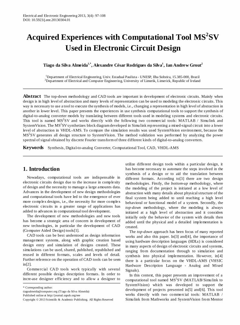
The translation of the model starts with reading a Simulink generated file with an .mdl extension. Initially, a check is made of elements and libraries used in model. If there are no unknown libraries or elements, the translation process starts. The tool stores a list of components in model, the list of connections between these components and other important informat ion for generation of circuit netlist. Then, p roject structure required for simulat ion and analysis in SystemVision is generated too[1]. Finally, all descriptions in VHDL - AMS and files for debugging for pro ject needs are generated. Figure 1 shows the functional diagram of the MS2SV tool.
If subsystems are used, a VHDL-AMS model for each subsystem used is generated. The MS2SV enables the relationship between elements in the same library by creating hierarchical models.
Figure 1. Functional diagram of the MS2SV tool illustrating the steps involved in translating the model to generate input file structure in SystemVision environment[1]
100 Tiago da Silva Almeida et al. : Acquired Experiences with Computational Tool MS2SV Used in Electronic Circuit Design
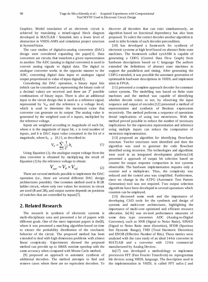
Figure 2. Class diagram of translations rules of MS2SV
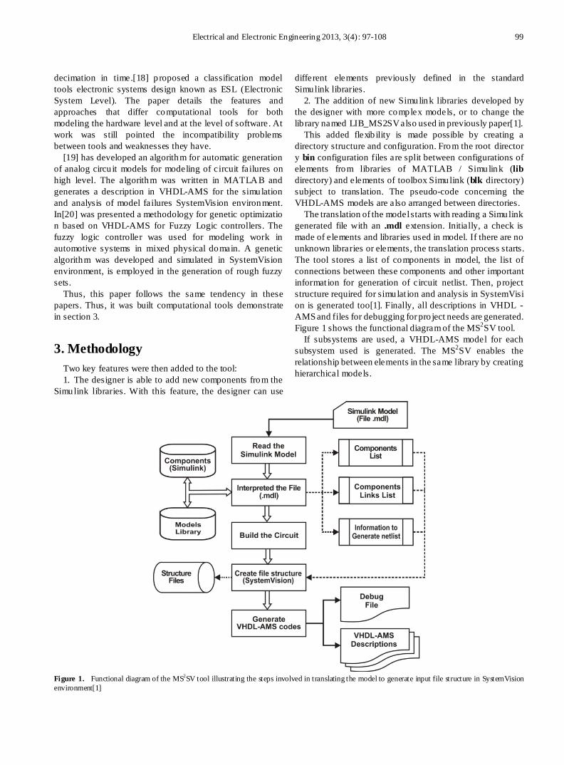
Figure 3. Sequence diagram of MS2SV tool illustrating translation process elements being primitive toolbox of Simulink without interaction with user libraries
Electrical and Electronic Engineering 2013, 3(4): 97-108 101
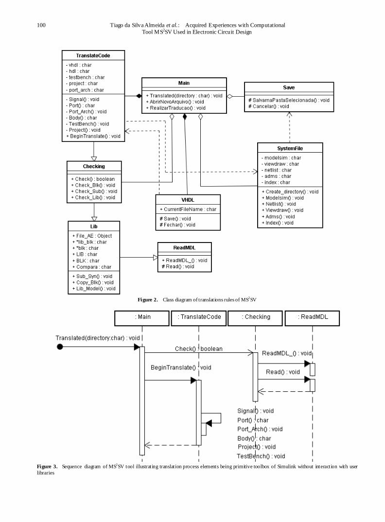
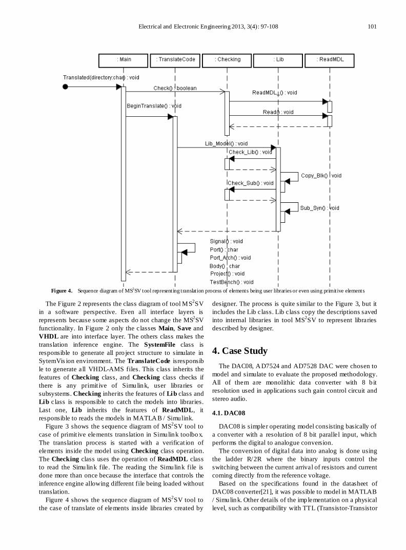
Figure 4. Sequence diagram of MS2SV tool representing translation process of elements being user libraries or even using primitive elements
The Figure 2 represents the class diagram of tool MS2SV in a software perspective. Even all interface layers is represents because some aspects do not change the MS2SV functionality. In Figure 2 only the classes Main, Save and VHDL are into interface layer. The others class makes the translation inference engine. The SystemFile class is responsible to generate all pro ject structure to simulate in SytemVis ion environment. The TranslateCode isresponsible to generate all VHDL-AMS files. This class inherits the features of Checking class, and Checking class checks if there is any primit ive of Simulink, user libraries or subsystems. Checking inherits the features of Lib class and Lib c lass is responsible to catch the models into libraries. Last one, Lib inherits the features of ReadMDL, it responsible to reads the models in MATLAB / Simulink.
Figure 3 shows the sequence diagram of MS2SV tool to case of primit ive elements translation in Simulink toolbox. The translation process is started with a verificat ion of elements inside the model using Checking class operation. The Checking class uses the operation of ReadMDL class to read the Simulink file . The reading the Simulink file is done more than once because the interface that controls the inference engine allowing different file being loaded without translation.
Figure 4 shows the sequence diagram of MS2SV tool to the case of translate of elements inside libraries created by
designer. The process is quite similar to the Figure 3, but it includes the Lib class. Lib class copy the descriptions saved into internal libraries in tool MS2SV to represent libraries described by designer.
4. Case Study The DAC08, AD7524 and AD7528 DAC were chosen to
model and simulate to evaluate the proposed methodology. All of them are monolithic data converter with 8 b it resolution used in applications such gain control circuit and stereo audio.
4.1. DAC08
DAC08 is simpler operating model consisting basically of a converter with a resolution of 8 bit parallel input, which performs the digital to analogue conversion.
The conversion of digital data into analog is done using the ladder R/2R where the binary inputs control the switching between the current arrival of resistors and current coming directly from the reference voltage.
Based on the specifications found in the datasheet of DAC08 converter[21], it was possible to model in MATLAB / Simulink. Other details of the implementation on a physical level, such as compatibility with TTL (Transistor-Transistor
102 Tiago da Silva Almeida et al. : Acquired Experiences with Computational Tool MS2SV Used in Electronic Circuit Design
Logic) and CMOS (Complementary Metal Oxide Semiconductor) technology were not considered, because the focus of this paper is modelling at high level of abstraction.
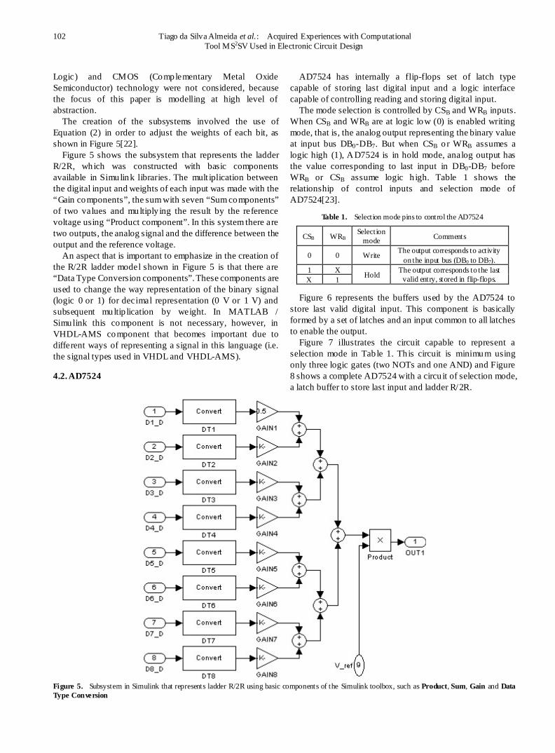
The creation of the subsystems involved the use of Equation (2) in order to adjust the weights of each bit, as shown in Figure 5[22].
Figure 5 shows the subsystem that represents the ladder R/2R, which was constructed with basic components available in Simulink libraries. The mult iplication between the digital input and weights of each input was made with the “Gain components”, the sum with seven “Sum components” of two values and multiply ing the result by the reference voltage using “Product component”. In this system there are two outputs, the analog signal and the difference between the output and the reference voltage.
An aspect that is important to emphasize in the creation of the R/2R ladder model shown in Figure 5 is that there are “Data Type Conversion components”. These components are used to change the way representation of the binary signal (logic 0 or 1) for decimal representation (0 V or 1 V) and subsequent multip lication by weight. In MATLAB / Simulink this component is not necessary, however, in VHDL-AMS component that becomes important due to different ways of representing a signal in this language (i.e. the signal types used in VHDL and VHDL-AMS).
4.2. AD7524
AD7524 has internally a flip-flops set of latch type capable of storing last digital input and a logic interface capable of controlling reading and storing digital input.
The mode selection is controlled by CSB and WRB inputs. When CSB and WRB are at logic low (0) is enabled writing mode, that is, the analog output representing the binary value at input bus DB0-DB7. But when CSB or WRB assumes a logic high (1), AD7524 is in hold mode, analog output has the value corresponding to last input in DB0-DB7 before WRB or CSB assume logic h igh. Table 1 shows the relationship of control inputs and selection mode of AD7524[23].
Table 1. Selection mode pins to control the AD7524
CSB WRB Selection mode Comments
0 0 Write The output corresponds to activity on the input bus (DB0 to DB7).
1 X Hold The output corresponds to the last valid entry, stored in flip-flops. X 1
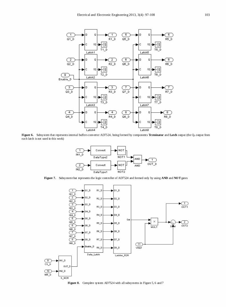
Figure 6 represents the buffers used by the AD7524 to store last valid digital input. This component is basically formed by a set of latches and an input common to all latches to enable the output.
Figure 7 illustrates the circuit capable to represent a selection mode in Tab le 1. Th is circuit is minimum using only three logic gates (two NOTs and one AND) and Figure 8 shows a complete AD7524 with a circu it of selection mode, a latch buffer to store last input and ladder R/2R.
Figure 5. Subsystem in Simulink that represents ladder R/2R using basic components of the Simulink toolbox, such as Product, Sum, Gain and Data Type Conversion
Electrical and Electronic Engineering 2013, 3(4): 97-108 103
Figure 6. Subsystem that represents internal buffers converter AD7524, being formed by components Terminator and Latch output (the Qb output from each latch is not used in this work)
Figure 7. Subsystem that represents the logic controller of AD7524 and formed only by using AND and NO T gates
Figure 8. Complete system AD7524 with all subsystems in Figure 5, 6 and 7
104 Tiago da Silva Almeida et al. : Acquired Experiences with Computational Tool MS2SV Used in Electronic Circuit Design
4.3. AD7528
AD7528 is equivalent to two AD7524 converters in a single IC (integrated circu it). The data bus of the AD7528 is also numbered from DB0 to DB7. Each internal converter (DAC A and DAC B) has an individual reference pin, both can vary ± 25 V. The AD7528 has only three control p ins called DACA/DACB, CSB and WRB. The relationship between control pins is illustrated in the Table 2. At a moment when the AD7528 is in hold mode the last valid input is stored in buffers individually in each internal converter[24].
Table 2. Selection mode pin to control the AD7528 indicating write mode of the DAC A with all pins active low logic level or in write mode DAC B only with pin in DACA/DACB active-high level, any change in the CSB pin or WRB both converters are in hold mode
DACA/DACB WRB CSB DAC A DAC B
0 0 0 Write Hold
1 0 0 Hold Write X 1 X Hold Hold X X 1 Hold Hold
According to the approach described in[24], we created two identical blocks to represent the ladder R/2R, one for the DAC A and one for the DAC B. Similar to R/2R ladder subsystem of Figure 5, the subsystem of Figure 6 was used twice in the complete system, i.e . one for each block of the AD7528 internal converter (DAC A and DAC B).
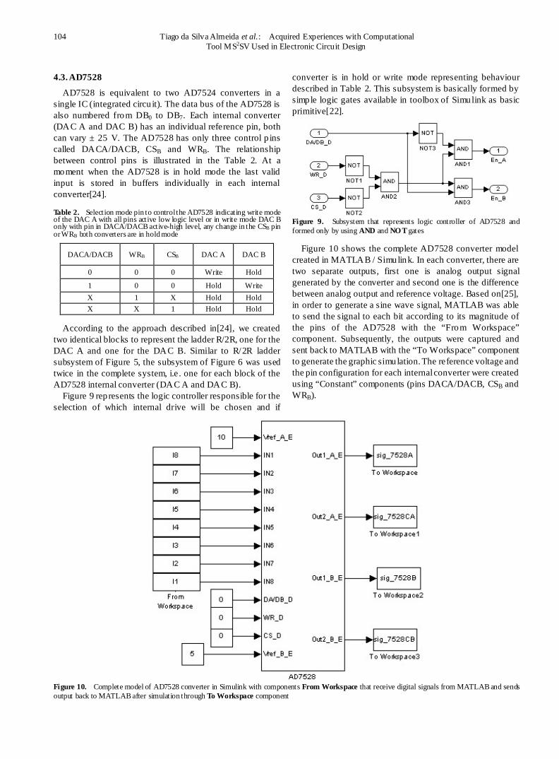
Figure 9 represents the logic controller responsible for the selection of which internal drive will be chosen and if
converter is in hold or write mode representing behaviour described in Table 2. This subsystem is basically formed by simple logic gates available in toolbox of Simulink as basic primitive[22].
Figure 9. Subsystem that represents logic controller of AD7528 and formed only by using AND and NO T gates
Figure 10 shows the complete AD7528 converter model created in MATLAB / Simulink. In each converter, there are two separate outputs, first one is analog output signal generated by the converter and second one is the difference between analog output and reference voltage. Based on[25], in order to generate a sine wave signal, MATLAB was able to send the signal to each bit according to its magnitude of the pins of the AD7528 with the “From Workspace” component. Subsequently, the outputs were captured and sent back to MATLAB with the “To Workspace” component to generate the graphic simulation. The reference voltage and the pin configuration for each internal converter were created using “Constant” components (pins DACA/DACB, CSB and WRB).
Figure 10. Complete model of AD7528 converter in Simulink with components From Workspace that receive digital signals from MATLAB and sends output back to MATLAB after simulation through To Workspace component
Electrical and Electronic Engineering 2013, 3(4): 97-108 105
The DACA/DACB pin could have been used to carry out switching between two converters internally creating two different waveforms from one input. However, as the converters are exactly the same, the kind of simulation does not alter the analysis of signal generated.
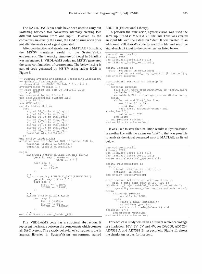
After construction and simulation in MATLAB / Simulink, the MS2SV translates model to the SystemVision environment. The h ierarchy structure of model in Simulink was maintained in VHDL-AMS codes and MS2SV generated the same configuration of components. The below listing is part of code generated by MS2SV using ladder R/2R in Figure 5.
-- Digital Systems and Signals Processing Laboratory -- genhdl\..\Ladder_R2R.vhd -- Generated by MS2SV (Matlab / Simulink to SystemVision) version 1.7 -- File created Tue Sep 08 16:00:12 2009 library IEEE; use ieee.std_logic_1164.all; use ieee.electrical_systems.all; library EduLib; use WORK.all; entity Ladder_R2R is port ( signal D1_D: in std_logic; signal D2_D: in std_logic; signal D3_D: in std_logic; signal D4_D: in std_logic; signal D5_D: in std_logic; signal D6_D: in std_logic; signal D7_D: in std_logic; signal D8_D: in std_logic; terminal A1: electrical ); end entity Ladder_R2R; architecture arch_Ladder_R2R of Ladder_R2R is terminal \1$N0\: electrical; terminal \1$N1\: electrical; ... begin DataType: entity EDULIB.D2A_BIT(IDEAL) generic map ( VHIGH => 1.0, VLOW => 0.0 ) port map ( D => D1_D, A => \1$N0\ ); ... E_Gain: entity EDULIB.E_GAIN(BEHAVIORAL) generic map ( K => 0.5 ) port map ( INPUT => \1$N0\, OUTPUT => \1$N8\ ); ... E_Sum: entity EDULIB.E_SUM port map ( IN1 => \1$N8\, IN2 => \1$N9\, OUTPUT => \1$N16\ ); ... end architecture arch_Ladder_R2R;
This VHDL-AMS code has a structural abstraction. It represent the linkage between the components which compos all DAC system. The exactly behavior o f components are in internal libraries in SystemVision environment named
EDULIB (Educational Library). To perform the simulat ion, SystemVis ion was used the
same input used in MATLAB / Simulink. Thus was created an input file with the extension “.dat”. It was created to an additional VHDL-AMS code to read this file and send the signal each bit input to the converters, as listed below.
use std.textio.all; library IEEE; use ieee.std_logic_1164.all; use IEEE.std_logic_textio.all; entity lerarqp is port (relogio: in std_logic; saida: out std_ulogic_vector (8 downto 1)); end entity lerarqp; architecture behavior of lerarqp is begin testing: process file f_in: text open READ_MODE is "input.dat"; variable L: LINE; variable L_BIT: std_ulogic_vector (8 downto 1); begin while not endfile(f_in) loop readline (f_in,L); hread (L,L_BIT); wait until (relogio'event) and (relogio='1'); saida <= L_BIT; end loop; end process testing; end architecture behavior;
It was used to save the simulation results in SystemVision in another file with the extension “.dat” to that was possible to analysis the signal generated also in MATLAB, as listed below.
use std.textio.all; library IEEE; use IEEE.std_logic_1164.all; use IEEE.std_logic_textio.all; --use IEEE.electrical_systems.all; entity writewaveform is port ( signal relogio: in std_logic; entrada: in real); end entity writewaveform; architecture behavior of writewaveform is file f_out: text open WRITE_MODE is "C:\Mentor_Projects\DAC08_Test\hdl\output.dat"; --quantity escreve_sinal across entrada to ref; begin writying: process variable L: LINE; begin write(L,REAL'(entrada)); writeline(f_out,L); wait until (relogio'event) and (relogio='1'); end process writying; end architecture behavior;
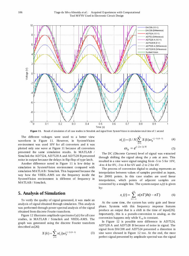
For each case study was used a different reference voltage in simulation, 10V, 8V, 6V and 4V, for DAC08, AD7524, AD7528 A and AD7528 B, respectively. Figure 11 shows the simulat ion results for 1 second.
106 Tiago da Silva Almeida et al. : Acquired Experiences with Computational Tool MS2SV Used in Electronic Circuit Design
Figure 11. Result of simulation of all case studies in Simulink and signal from SystemVision in simulation total t ime of 1 second
The different voltages were used to a better view waveform in Figure 11. However, in SystemVision environment was used 10V for all converters and it was plotted only one wave at Figure 11 because all converters presented the same simulation results. In MATLAB / Simulink the AD7524, AD7528 A and AD7528 B presented noise in output because the delays in flip-flop of type latch.
Another difference noted in Figure 11 is low delay in simulation in SystemVision environment compared with simulation MATLAB / Simulink. Th is happened because the way how the VHDL-AMS see the frequency inside the SystemVision environment is different of frequency in MATLAB / Simulink.
5. Analysis of Simulation To verify the quality of signal generated, it was made an
analysis of signal obtained through simulat ion. This analysis was performed through power spectral analysis of the signal obtained from discrete Fourier transform.
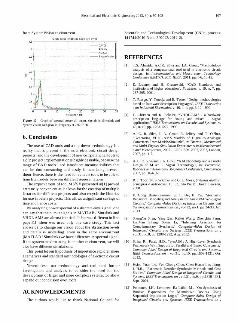
Figure 12 illustrates amplitude spectrum of y(t) for all case studies, in MATLAB / Simulink and VHDL-AMS. The graph was generated using the discrete Fourier transform described as[26]:
( 1) ( 1)
1( ) ( )
Nj k
Nj
X k x j ω − −
==∑ (3)
( 1) ( 1)
1( ) (1/ ) ( )
Nj k
Bk
x j N X k ω− − −
== ∑ (4)
( 2 )/i NN e πω −= (5)
The DC (Discrete Current) level of signal was extracted through shifting the signal along the y axis at zero. This resulted in a sine wave signal ranging from -5 to 5 for 10V, -4 to 4 for 8V, -3 to 4 for 6V and -2 to 2 for 4V.
The process of conversion digital to analog represents an interpolation between values of samples provided as inputs, for 20001 points. In this case studies are used linear interpolation, which points of adjacent samples are connected by a straight line. The system output xr(t) is given by:
( ) ( ) ( )rn
x t x nT h t nT+∞
−∞== −∑ (6)
At the same time, the system has unity gain and linear phase. Systems with this frequency response features produce an output that is a shift in the time of input[26]. Importantly, this is a pseudo-conversion to analog, as the conversion happens only while Vref is constant.
In Figure 12 is possible note difference in AD7524, AD7528 A and AD7528 B because of noise in signal. The signal from DAC08 and AD7524 presented a distortion in sine wave showed in Figure 12 too. At the end, the most perfect signal presented by amplitude spectral was the signal
Electrical and Electronic Engineering 2013, 3(4): 97-108 107
from SystemVision environment.
Figure 12. Graph of spectral power all output signals in Simulink and SystemVision with peak in frequency at 2.9297 Hz
6. Conclusions The use of CAD tools and a top-down methodology is a
reality that is present in the most electronic circu it design projects, and the development of new computational tools to aid in pro ject implementation is h ighly desirable, because the range of CAD tools used introduces incompatibilities that can be time consuming and costly in translating between them. Hence, there is the need for suitable tools to be able to translate models between different representations.
The improvement of tool MS2SV presented in[1] proved extremely convenient as it allows for the creation of multip le lib raries for d ifferent projects and also recycle the libraries for use in others projects. This allows a significant savings of time and hence costs.
By analyzing power spectral of a discrete-time signal, one can say that the output signals in MATLAB / Simulink and VHDL-AMS are almost identical. It fact was d ifferent in first paper[1] when was used only one case study. This fact allows us to change our vision about the abstraction levels and details in modelling. Even in the same environment (MATLAB / Simulink) we have difference in spectral signal. If the system be simulating in another environment, we will also have different simulat ions.
This point let our hypothesis of importance explorer more alternatives and standard methodologies of electronic circu it design.
Nevertheless, our methodology and tool need further investigation and analysis to consider the need for the development of larger and more complex systems. To allow expand our conclusion even more.
ACKNOWLEDGMENTS The authors would like to thank National Council for
Scientific and Technological Development (CNPq, process: 141744/2010-3 and 309023/2012-2).
REFERENCES [1] T.S. Almeida, A.C.R. Silva and I.A. Grout, "Methodology
analysis of a computational tool used in electronic circuit design," in: Instrumentation and Measurement Technology Conference (I2MTC), 2011 IEEE , 2011, pp.1-6, 10-12.
[2] E. Erdener and H. Gruenwald, “CAD Standards and institutions of higher education”, Facilities, v. 19, n. 7, pp. 287-295, 2001.
[3] T. Riesgo, Y. Torroja and E. Torre, “Design methodologies based on hardware description languages”, IEEE Transactions on Industrial Electronics, v. 46, n. 1, pp. 3-12, 1999.
[4] E. Christen and K. Bakalar, “VHDL-AMS - a hardware description language for analog and mixed - signal applications” IEEE Transactions on Circuits and Systems, v. 46, n. 10, pp. 1263-1272, 1999.
[5] A. C. R. Silva, I. A. Grout, R. Jeffrey and T. O'Shea, “Generating VHDL-AMS Models of Digital-to-Analogue Converters From Matlab/Simulink”, in: Thermal, Mechanical and Multi-Physics Simulation Experiments in Microelectronic and Microsystems, 2007 - EUROSIM 2007, 2007, London, 2007, pp. 1-7.
[6] A. C. R. Silva and I. A. Grout, “A Methodology and a Tool to Design of Mixed - Signal Technology”, in: Electronic, Robotics and Automotive Mechanics Conference, Cuernavaca. 2007, pp. 164-169.
[7] R. J. Tocci, N. S. Widmer and G. L. Moss, Sistemas digitais: princípios e aplicações, 10. Ed, São Paulo, Brazil: Pearson, 2008.
[8] F. Gong; Basir-Kazeruni, S.; L. He; H. Yu, "Stochastic Behavioral Modeling and Analysis for Analog/Mixed-Signal Circuits," Computer-Aided Design of Integrated Circuits and Systems, IEEE Transactions on , vol.32, no.1, pp.24-33, Jan. 2013.
[9] ShengYu Shen; Ying Qin; KeFei Wang; Zhengbin Pang; JianMin Zhang; Sikun Li, "Inferring Assertion for Complementary Synthesis," Computer-Aided Design of Integrated Circuits and Sys tems, IEEE Transactions on , vol.31, no.8, pp.1288-1292, Aug. 2012.
[10] Sinha, R.; Patel, H.D., "synASM: A High-Level Synthesis Framework With Support for Parallel and Timed Constructs," Computer-Aided Design of Integrated Circuits and Systems, IEEE Transactions on , vol.31, no.10, pp.1508-1521, Oct. 2012.
[11] Hsiou-Yuan Liu; Yen-Cheng Chou; Chen-Hsuan Lin; Jiang, J.-H.R., "Automatic Decoder Synthesis: Methods and Case Studies," Computer-Aided Design of Integrated Circuits and Systems, IEEE Transactions on , vol.31, no.9, pp.1319-1331, Sept. 2001.
[12] Poikonen, J.H.; Lehtonen, E.; Laiho, M., "On Synthesis of Boolean Expressions for Memristive Devices Using Sequential Implication Logic," Computer-Aided Design of Integrated Circuits and Sys tems, IEEE Transactions on ,
108 Tiago da Silva Almeida et al. : Acquired Experiences with Computational Tool MS2SV Used in Electronic Circuit Design
vol.31, no.7, pp.1129-1134, July 2012.
[13] X. Wu et al, “Research and Application of Code Automatic Generation Algorithm Based on Structured Flowchart”, Journal of Software Engineering And Applications, v. 4, n. 9, pp.534-545, 2011.
[14] Wei-Cheng Lien; Kuen-Jong Lee; Tong-Yu Hsieh; Chakrabarty, K; Yu-Hua Wu, "Counter-Based Output Selection for Test Response Compaction," Computer-Aided Design of Integrated Circuits and Systems, IEEE Transactions on , vol.32, no.1, pp.152-164, Jan. 2013.
[15] D. Marculescu and P. Li, “Guest editorial special section on PAR-CAD: parallel CAD algorithms and CAD for parallel architecture / systems”, Computer-Aided Design of Integrated Circuits and Systems, IEEE Transactions on, v. 31, n. 1, p. 7-8, 2012.
[16] Pedroso Meloni, L.G.; Gusso Lenzi, K., "Performance Measurement Simulations for Analog-to-Digital Converters," Latin America Transactions, IEEE (Revista IEEE America Latina) , vol.10, no.1, pp.1168-1174, Jan. 2012.
[17] Correa, I. S.; Freitas, L.C.; Klautau, A.; Weyl Albuquerque Costa, J.C., "VHDL Implementation of a Flexible and Synthesizable FFT Processor," Latin America Transactions, IEEE (Revista IEEE America Latina), vol.10, no.1, pp.1180-1183, Jan. 2012.
[18] Gerstlauer, A.; Haubelt, C.; Pimentel, A.D.; Stefanov, T.P.; Gajski, D.D.; Teich, J., "Electronic System-Level Synthesis Methodologies," Computer-Aided Design of Integrated Circuits and Systems, IEEE Transactions on , vol.28, no.10, pp.1517-1530, Oct. 2009.
[19] Likun Xia; Bell, I.M.; Wilkinson, A.J., "Automated Model Generation Algorithm for High-Level Fault Modeling," Computer-Aided Design of Integrated Circuits and Systems, IEEE Transactions on , vol.29, no.7, pp.1140-1145, July 2010.
[20] L. Wang and T. J. Kazmierski, “VHDL-AMS based genetic optimization of fuzzy logic controllers’, The International Journal for Computation and Mathematics in Electrical and Electronic Engineering, v. 26, n. 2, pp. 447-460, 2007
[21] Analog Devices Inc. (2010) CMOS dual 8-bit buffered multiplying DAC: AD7528[Online]. Available http://www. datasheetcatalog.org/datasheet/analogdevices/78586868AD 7528_b.pdf.
[22] E. Y. Matsumoto, Simulink 7.2: Guia Prático, São Paulo, Brazil: Érica, 2008.
[23] Analog Devices Inc. (2002) CMOS 8-Bit Buffered Multiplying DAC: AD7524[Online]. Available http:// www. datasheetcatalog.org/datasheet/analogdevices/888358036ad7524.pdf.
[24] Analog Devices Inc. (2002) 8-Bit, High-Speed, Multiplying D/A Converter (Universal Digital Logic Interface) DAC: DAC08[Online]. Available http://www. datasheetcata log. Org / datasheet/ analogdevices/80487346DAC08_b.pdf.
[25] E. Y. Matsumoto, Matlab 7: Fundamentos, São Paulo, Brazil: Érica, 2010.
[26] A. V. Oppenheim, A. S. Willsky, Sinais e sistemas, São Paulo, Brazil: Person Education, 2010.