acs100um rev 1.0 09-22-09 - electrocraft · this manual covers the use and maintenance of the model...
TRANSCRIPT

ElectroCraft Incorporated
MODEL ACS100-XXXX
User’s Manual
Digital Velocity/Torque/Position Mode Servo Drive
This manual covers the use and maintenance of the model ACS100 series Torque, Velocity and Position mode brushless motor control product family.

ACS100 User Manual
ElectroCraft, Inc.
2
Title: ACS100 User Manual Installation and Operation
Type of Documentation: User Hardware Manual
Document Type code: ACS100UM Rev 1.0 09‐22‐09.doc
Internal File Reference: Document Number: A11013
Purpose of Documentation: This documentation describes…
• Installation and operation of the ACS100 family drive.
Record of Revisions: RELEASE NUMBER DATE DESCRIPTION COMMENTS 1.0 09/22/2009 ElectroCraft Mi Initial Release
Copyright: ©2009 ElectroCraft MI, Inc USA. All rights Reserved.
Copying this document, giving it to others and the use or communication of the contents there of without express authority, is forbidden. Offenders are liable for the payment of damages. We reserve the right to modify our products at any time. Information, specifications, and material data that appear within this user manual are subject to change without notice. For the latest revision of this manual, please check our web site or contact ElectroCraft.
Validity: The specified data is for product description purposes only and may not be deemed to be guaranteed unless expressly confirmed in the contract. All rights are reserved with respect to the content of this documentation and the availability of the product
Published by: ElectroCraft MI, Incorporated P.O. Box 7746, Ann Arbor, Michigan 48108 USA Tel.: 734‐662‐7771 • Fax: 734‐662‐3707
http://www.electrocraft.com
ACS100 User Manual
ElectroCraft, Inc.
3
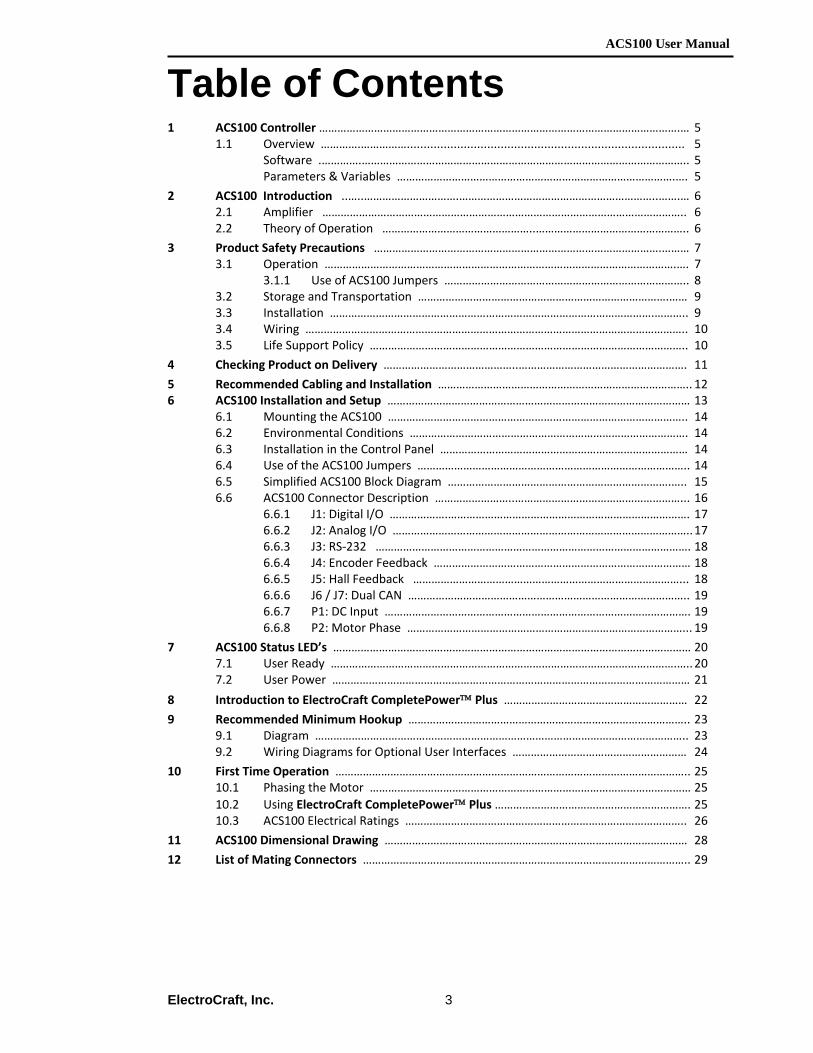
Table of Contents 1 ACS100 Controller ……………………………………………………………………………………………………….… 5
1.1 Overview ………….……………................................................................................... 5 Software .………….…………………………………………………………………………………………….. 5
Parameters & Variables ……………………………………………………………………………….…. 5
2 ACS100 Introduction ..…..………………………….………………………………………………………..…….… 6 2.1 Amplifier ……………………………………………………………………………………………………….. 6 2.2 Theory of Operation …………………………………………..………………………………………….. 6
3 Product Safety Precautions ………………………………………………………………………………….……… 7 3.1 Operation …………………………………………………………………………………………………….…. 7 3.1.1 Use of ACS100 Jumpers …………………………………………………………………….. 8 3.2 Storage and Transportation ……………………………………………………………………….…… 9 3.3 Installation …………………………………………………………………………………………….……….. 9 3.4 Wiring …………………………………………………………………………………………………………….. 10 3.5 Life Support Policy ………………………………………………………………………………………….. 10
4 Checking Product on Delivery ……………………………………..………………………………………………. 11
5 Recommended Cabling and Installation ……………………………………………………………………….. 12 6 ACS100 Installation and Setup ……………………………………………………………………………………… 13 6.1 Mounting the ACS100 …………………………………………………………………………………….. 14 6.2 Environmental Conditions ………………………………………………………………………………. 14 6.3 Installation in the Control Panel ……………………………………………………………………… 14 6.4 Use of the ACS100 Jumpers …………………………………………………………………………….. 14
6.5 Simplified ACS100 Block Diagram ……………………………………………………………….….. 15 6.6 ACS100 Connector Description ……………………..………………………………………………... 16 6.6.1 J1: Digital I/O ……………….……………………………………………………………………. 17 6.6.2 J2: Analog I/O …………………………………………………………………………………….. 17 6.6.3 J3: RS‐232 …………………………………………………………………………………………. 18 6.6.4 J4: Encoder Feedback ………………………………………………………………………… 18 6.6.5 J5: Hall Feedback ……………………………………………………………………………... 18 6.6.6 J6 / J7: Dual CAN ……………………………………………………………………………….. 19 6.6.7 P1: DC Input ………………………………………………………………………………………. 19 6.6.8 P2: Motor Phase ………………………………………………………………………………... 19
7 ACS100 Status LED’s ……………………………………………………………………………………………………… 20 7.1 User Ready ……………………………………………………………………………….………………….….. 20 7.2 User Power ……………………………………………………………………………………………………… 21
8 Introduction to ElectroCraft CompletePower™ Plus …………………………………………………… 22
9 Recommended Minimum Hookup ……………………………………………………………………………….. 23 9.1 Diagram ………………………………………………………………………………………………………….. 23 9.2 Wiring Diagrams for Optional User Interfaces ………………………………………………… 24
10 First Time Operation …………………………………………………………………………………………………….. 25 10.1 Phasing the Motor …………………………………………………………………………………………… 25 10.2 Using ElectroCraft CompletePower™ Plus ………………………………………………………. 25 10.3 ACS100 Electrical Ratings ……………………………………………………………………………….. 26
11 ACS100 Dimensional Drawing ……………………………………………………………………………………… 28
12 List of Mating Connectors …………………………………………………………………………………………….. 29

ACS100 User Manual
ElectroCraft, Inc.
4
13 ACS100 Interface Circuitry ……………………………………………………………………………………………. 30 13.1 J1: Digital I/O …………………………………………………………………………………………………… 30 13.2 J2: Analog I/O ………………………………………………………………………………………………….. 31 13.3 J3: RS‐232 Interface …………………………………………………………………………………………. 32 13.4 J4: Encoder Interface Overview ……………………………………………………………………… 33 13.4.1 J4: Encoder Interface ………………………………………………………………………… 33
13.5 J5: Hall Interface Overview …………………………………………………………………………….. 33 13.5.1 J5: Hall Interface ………………………………………………………………………………. 33
13.6 J6 and J7: CAN Interface …………………………………………………………………………………. 34 13.7 Motor Temperature Overview ………………………………………………………………………… 35 13.7.1 Motor Temperature ………………………………………………………………………….. 35
14 External Shunt ……………………………………………………………………………………………………………….. 36 14.1 Use & Selection ………………………………………………………………………………………………… 36 14.2 Connecting shunt board ………………………………………………………………………………….. 37
15 Model Identification ……………………………………………………………………………………………………... 38 16 Appendix A ……………………………………………………………………………………………………………………. 39
The remainder of this page is intentionally left blank.

ACS100 User Manual
ElectroCraft, Inc.
5
1 ACS100 Controller
1.1 Overview
This manual describes the installation and operation of the ACS100 series of digital high voltage servo‐amplifiers manufactured by ElectroCraft MI, Inc. This document applies to serial numbers ending with xxxx0105 and beyond. The ACS100 amplifier is: • Configurable operation modes: Torque, Velocity, and Position. • Selectable BLAC (sine wave, flux vector) or BLDC (Six step, trapezoidal)
commutation. • 4 Quadrant performance. • Phase output, PWM controlled output. • Full digital control of all loops • Variable servo rate from up to 16 kHz. • Loop tuning via serial interface (No potentiometers!). • Drive setup & status information available serially via RS232 link. • 12 – 48 VDC input power supply range. • Output current of 5.0 Amp continuous, 10 Amp peak. • Compact package size. • ElectroCraft CompletePower™ Plus graphical windows interface for Setup,
Configuration and Tuning.
Software For further documentation support of software and its usage, refer to the ElectroCraft
CompletePower™ Plus software user’s manual.
Parameters and Variables
For further documentation support of parameters, variables, commands and graphing refer to the ElectroCraft Parameter Guide.

ACS100 User Manual
ElectroCraft, Inc.
6
2 ACS100 Introduction
2.1 Amplifier The ACS100 is a fully digital servo amplifier that uses DSP technology to provide a powerful feature set that is fully configurable by means of a RS232 serial port. The ACS100 servo drive is configurable as a Torque, Velocity, or Position mode servo amplifier. The ACS100 is designed to operate a single 3 phase Brushed or Brushless DC or AC, permanent magnet motor. The motor may have either a WYE or Delta wound stator. The ACS100 provides commutation using Hall sensors or encoder feedback. The ACS100 Torque, Velocity or Position modes accept +/‐ 10 volt DC analog or digital PWM.
2.2 Theory of Operation The ACS100 operates as a “mode configurable” digital servo amplifier. This product is typically applied as a component within an end use industrial application. Within industry, application requirements for servo amplifiers vary widely. For example, one application may require an amplifier with an analog input reference for speed. Another application may require an amplifier that offers torque control and Hall sensor commutation only. For this reason the ACS100 offers a choice of many different servo‐operating modes. This flexibility is made possible because all of the control functions within the ACS100 are implemented in software. The ACS100 physical I/O and closed loop functionality are selected using the ElectroCraft CompletePower™ Plus software setup utility. See Section 7, Introduction to the ElectroCraft CompletePower™ Plus software, and the ElectroCraft CompletePower™ Plus software User Manual for additional information on using this software. The internal firmware architecture of the ACS100 is modular. ACS100 software is built as a series of components (or modules) that are linked together to form an ACS100 servo‐operating mode. ACS100 software components are stored in flash memory. These components exist as Reference input modules, Feedback modules, PI (D) control modules, commutation modules and firmware extension modules. An internal digital signal processor is used to read I/O signals, motor feedback signals and to process serial communication messages. Flash memory inside the ACS100 is used to store a library of modular software components. RAM memory is used for data logging and graphical tuning of the ACS100. The serial EEPROM provides nonvolatile memory for retention of user‐configured parameters and operating mode.

ACS100 User Manual
ElectroCraft, Inc.
7
3 Product Safety Precautions READ THIS ENTIRE SECTION BEFORE ATTEMPTING TO USE THE ACS100 SERVO DRIVE! GIVE SPECIAL ATTENTION TO ALL BOLD PRINT ITEMS.
WARNING! To operate your control successfully, these minimum safety precautions MUST be followed to insure proper performance without injury to the operator and damage to motor or control. FAILURE TO OBSERVE THESE SAFETY PRECAUTIONS COULD RESULT IN SERIOUS BODILY INJURY, INCLUDING DEATH IN EXTREME CASES.
3.1 Operation
1. Do not touch any of the output connector pins from connectors P1 (DC Input) or P2 (Motor Output) when power has been applied. The voltages at these connector pins are dangerous and can produce an electric shock. Bare wires from adjacent connector pins must never be allowed to touch one another.
2. P1 pin 4, must be connected to an external earth ground. Follow wiring procedures carefully. Know and understand which connectors are NOT electrically isolated from the DC voltages within the drive.
3. Read ElectroCraft’s Life Support Policy in section 3.5 for application limitations.
4. Follow precautionary guidelines in this manual with regard to proper installation of an external
shunt resistor. See Section 13 of this manual.
5. Do not operate the control in an explosive area or near explosive or flammable materials.
6. Do not use the control in environments where it is likely to be exposed to strong and/or frequent static discharge.
7. Conduct trial operations on the servo drive alone with the motor shaft disconnected from the machine to avoid any unexpected accidents. Motor shaft should be uncoupled and free to rotate without coming in contact with user or any stationary object during set up and preliminary operation.
8. Under no circumstances should a phase output from the control be connected to anything
other than a passive inductive/resistive motor load. Short circuit protection for the drive is limited to momentary conditions only! Repetitive short circuits on any of the output pins for P2 will likely cause permanent damage to the ACS100.
9. Never touch any moving parts while the motor is running. Failure to observe this warning may
result in injury. 10. Excessive speed and current can destroy some motors and possibly injure the user. Check the
motor manufacturer's specifications to ensure that the maximum current and voltage for your control model, does not exceed their limitations.

ACS100 User Manual
ElectroCraft, Inc.
8
11. External methods are advisable to limit both the top speed and travel motion of the motor and its load. Whenever the ACS100 drive is disabled for any reason, the motor is placed into a free/spinning coast mode.
12. When using the servomotor for a vertical axis, install safety devices to prevent work pieces from moving due to occurrences of over travel. Failure to do this may cause injury to work pieces or person.
13. Provide an appropriate stopping device on the machine side to ensure safety. A holding brake for a servomotor with brake is not a stopping device for ensuring safely. Failure to observe this warning may result in injury.
14. Do not parallel multiple motors off the same control. 15. Do not make any extreme adjustments or settings changes of parameters. Failure to observe
this caution may result in injury due to instable operation. 16. Do not turn the control on or off frequently unless necessary. Failure to observe this caution
may cause internal parts to deteriorate.
17. Avoid frequently plugging connector P1 into the control while live power is applied to the connecting cables. Ignoring this precaution will cause electrical arcing at the connector pins, which can cause permanent connector damage. ElectroCraft recommends using a disconnect switch ahead of P1 if the ACS100 must be disconnected often.
18. Do not remove the connectors on ports P1, P2, J1 through J6 from the control while the motor is operating.
19. Do not service or modify this product. Only authorized personnel must perform disassembly or repair of the drive. Failure to observe warning may result in injury or damage to product.
3.1.1 Use of ACS100 Jumpers
ACS100 Jumpers JU201 and JU202 – DC Operating Voltage
1. The ACS100 has two jumpers that must be set according to the desired input DC operating voltage range. Failure to set these jumpers correctly can result in permanent damage to the ACS100. Please see section 3.3 “Use of ACS100 Jumpers JU201 and JU202” and select the proper jumper setting for your application before applying power to the ACS100.
ACS100 Jumpers JU1, JU2, JU3, JU4 – Use of Encoder Feedback 1. The ACS100 has jumpers that must be set according to the type of feedback device used.
When a differential encoder feedback is used A, A!, B, and B!, you can leave Z and Z! unconnected. If a single ended encoder feedback A and B, (and not the A! and B!)is used, all four jumpers on the daughter card, right next to the encoder connector J4, must be shorted. These are JU1, JU2, JU3 and JU4. You can then leave Z and Z! unconnected.
2. If only Hall Effect is used and no encoder at all, leave the encoder connector unconnected. 3. See section 6.6.4, J4 Encoder Interface Circuitry, for additional information.

ACS100 User Manual
ElectroCraft, Inc.
9
3.2 Storage and Transportation
1. Do not store or install the product in the following place a. Locations subject to temperature outside of the range specified. b. Locations subject to humidity outside the range specified. c. Locations subject to condensation as the result of extreme changes in temperature. d. Locations subject to corrosive or flammable gases. e. Locations subject to dust, salts, or iron contaminants. f. Locations subject to exposure to water, oil, or chemicals. g. Locations subject to shock or vibration.
Failure to observe this caution may result in fire, electric shock, damage to the product.
2. Do not hold the product by the cables or motor shaft while transporting it. Failure to observe this caution may result in injury or malfunction.
3. Store the ACS100 drive when not in use, in temperatures between ‐20 to +85 degrees C.
3.3 Installation
4. Take appropriate and sufficient countermeasures when installing systems in the following locations.
a. Locations subject to static electricity or other forms of noise. b. Locations subject to strong electromagnetic fields and magnetic fields. c. Locations subject to possible exposure to radioactivity. d. Locations close to power supplies including power lines.
Failure to observe this caution may result in damage to the product. 5. Keep any external shunt resistor away from flammable materials. Read Section 13 carefully for
more shunt installation details. 6. Never use this product in an environment subject to liquids, corrosive chemicals or gases, or
combustibles, or where foreign materials are allowed to fall onto or collect inside the drive Failure to observe this caution may result in electric shock or fire.
7. Do not place heavy objects on the product. Failure to observe this warning may result in stopping operation of the product.
8. Do not cover or prevent air from escaping or entering through the vents with obstruction or foreign object. Failure to observe this caution may cause internal elements to deteriorate resulting in malfunction or fire.
9. Provide the specified clearance between the drive and the control panel or with other devices. Provide sufficient space around the drive for cooling by natural convection or provide cooling fans to prevent excessive heat, see section 6.3 for details. Failure to observe this caution may result in fire or malfunction.

ACS100 User Manual
ElectroCraft, Inc.
10
3.4 Wiring 1. Verify ALL wiring BEFORE applying power to the control and motor. Motor may RUN AWAY or
oscillate uncontrollably if improperly wired. Drive may be damage or improper wiring may prevent drive from operation.
2. The ground P1, pin 3 or 4, MUST always be connected to an appropriate external earth ground. 3. Connect the ground terminal to the electrical codes (ground resistance should be less than 100
ohms. Improper grounding may result in electric shock or fire. 4. Do not connect a three‐phases or any supply power to the U, V, and W terminals. Failure to
observe this caution may result in injury or fire. 5. Securely connect the power supply terminals and motor output terminals. Failure to observe this
caution may result in fire. 6. Do not bundle or run power and signal lines together in the same duct. Keep power and signal lines
separated by at least 30cm. 7. Use twisted‐pair shielded wires or multi‐core twisted pair shielded wires for signal and encoder
feedback lines. 8. Always use the specified power supply voltage. An incorrect voltage may result in burning. Be
particularly careful where the power supply is unstable. An incorrect power supply may result in damage to the product.
9. Install external breakers or other safety devices against short‐circuiting in external wiring. Failure to
observe this caution may result in fire or damage to the control.
3.5 Life Support Policy READ THIS ENTIRE SECTION BEFORE ATTEMPTING TO USE THE ACE SERVO DRIVE! GIVE SPECIAL ATTENTION TO ALL BOLD PRINT ITEMS. ElectroCraft’s products are not authorized for use as critical components in life support devices or systems without the express written approval from ElectroCraft MI, Incorporated. 1. Life support devices or systems, are devices or systems which are intended for surgical implant into
the body, or support or sustain life, and whose failure to perform, when properly used in accordance with instructions for use provided in the User's Manual and in the labeling, can be reasonable expected to result in a significant injury to the user.
2. A critical component is any component of a life support device or system whose failure to perform
can be reasonably expected to cause the failure of the life support device or system, or to affect its safety or effectiveness.

ACS100 User Manual
ElectroCraft, Inc.
11
4 Checking Product on Delivery When your package arrives, inspect the shipping box and the unit carefully, and save ALL packing materials. Compare the packing slip against all items included in the shipping box. Any shortages or other inspection problems should be reported to ElectroCraft immediately. The following procedure is used to check products upon delivery. Check the following items when your ACS100 is delivered.
• Verify that the model number marked on the nameplate of the drive(s) is the correct unit ordered.
• Check the overall appearance. Check for damage or scratches that may have occurred during shipping.
If any damage, or if the unit is the wrong type, contact your ElectroCraft sales representative immediately. Your ACS100 has arrived carefully packaged from ElectroCraft MI, in an antistatic bag. As you unseal this bag, inspect the contents carefully. There should not be any loose or damaged parts inside. Never attempt to operate or power‐up the drive if there is any visible external damage or if it sounds as though there are loose materials inside the chassis. While unpacking, if you discover any loose or damaged parts, notify ElectroCraft within two working days. ElectroCraft recommends that all packing materials be saved in the event that the ACS100 needs to be shipped back. Always place the ACS100 in the same antistatic bag used in the original shipment. Abundant anti‐static filler material should always be placed around the ACS100 so that it cannot shift inside the box. Extreme care should be exercised when placing packing material around all external connectors to prevent mechanical stress damage. All material to be returned to ElectroCraft must have a Return Material Authorization (RMA) tracking number assigned before shipment. This may be obtained by contacting the ElectroCraft Service Dept. Any product returned without this number will be rejected by ElectroCraft. Always insure your shipment for the proper replacement value of its contents. ElectroCraft will not assume responsibility for any returned goods that have been damaged outside of our factory because of improper packaging or handling. All goods shipped to ElectroCraft must be shipped FREIGHT PREPAID.
ACS100 User Manual
ElectroCraft, Inc.
12
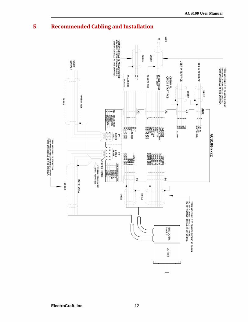
5 Recommended Cabling and Installation
ACS100-xxxx
USER SUPPLY
OPTIONALQUICK START PCB
KEEP FRAME GROUND WIRESAS SHORT AS POSSIBLE
POWER
INPUTM
OTORPHASE
ENC
OD
ER /
HALLS
MO
TOR
USER INTERFACE
USER INTERFACE
12345678910
+5VDC OUT+5VDC OUTENABLE / RESETRUN / STOPSTEPDIRECTIONENABLEDREADYDIGITAL GNDDIGITAL GND
123456
+5VDC HALL
HALL 3
HALL 1HALL 2
DIGITAL GNDDIGITAL GND
123456789
+5VDC ENC
ENCODER B
ENCODER AENCODER !A
ENCODER !BENCODER Z
DIGITAL GNDENCODER !Z
DIGITAL GND
WV
UF
J4J1
J5
P1
P2
SHIELD
SHIELD
SHIELD
SHIELD
SHIELD
SHIELD
AN1+AN1-
ANALOG GND
COMM
ON GND
1234567
AN1+AN1-ANALOG GNDAN2+AN2-ANALOG GNDANALOG GND
J2
ENABLE / RESETRUN / STOP
+-
PHASE U
TEMP +
PHASE VPHASE W
TEMP -
FRAME
123456
PINDESCRIPTION
VDC LOGIC+
MOTOR -
MOTOR+
VDC LOGIC -
1234
PINDESCRIPTION
POWER CABLE
MOTOR CABLE
12345
TXD
RTS
RXDCTS
DIGITAL GND
J3SHIELD
123
CAN HICAN LODIGITAL GND
J6/7SHIELD
+5VDC
TO PIN 6 (FRAME)
41
23
61
34
P/N 1001436
TERMINATE SHIELD TO ANALOG GROUND
SEPARATELY FROM COM
MON GROUND.
TERMINATE SHIELD AT THIS END ONLY.
TERMINATE SHIELD TO COM
MON GROUND
SEPARATELY FROM ANALOG GROUND .
TERMINATE SHIELD AT THIS END ONLY.
TERMINATE SHIELD TO COM
MON GROUND AS SHOW
N.DO NOT CONNECT SHIELD TO FRAM
E.DO NOT CONNECT SHIELD AT M
OTOR END.
TERMINATE SHIELDS FOR M
OTORAND POW
ER CABLE TO FRAME GROUND.
TERMINATE SHIELD AT THIS END ONLY.

ACS100 User Manual
ElectroCraft, Inc.
13
6 ACS100 Installation and Setup
READ ENTIRE USER MANUAL FIRST BEFORE ATTEMPTING TO USE THIS PRODUCT.
If you require further assistance then provided within this manual, please email, call, or fax:
ElectroCraft MI, Incorporated®
P.O. Box 7746 Ann Arbor, MI USA 48107
(734) 662-7771
Fax #(734) 662-3707
www.electrocraft.com
This chapter presents installation procedures and instructions on how to setup your ACS100 drive.
The remainder of this page is intentionally left blank.

ACS100 User Manual
ElectroCraft, Inc.
14
6.1 Mounting the ACS100
Use this preferred hardware type, see table below, for mounting your ACS100 drive. Mount your ACS100 in the following manner. Base Mounted: Two M3/ No. 6 pan head screws. Include spring (locking) washer with plain washer. Weight: 182g (0.40lb) Size: 3.0” (76.2mm) x 4.5” (114.3mm) x 0.942” (23.93mm).
6.2 Environmental Conditions in the Control Panel
• Storage Temperature: ‐20‐85 degree C • Humidity: 5‐95%RH, Non‐condensing • Operating Temperature range: 0‐50 degree C • Vibration Install a vibration isolator beneath the drive to avoid
subjecting it to vibration
6.3 Installation in the Control Panel Base Mount When installing the ACS100, provide at least 10 mm (0.39 in) between units or control panel and at least 50 mm (1.97 in) above and below each drive. Install cooling fans above or below the drive to maintain a constant temperature inside the control panel and to prevent an excess temperature rise around the drive.
6.4 Use of the ACS100 Jumpers JU201 and JU202
Jumpers JU201 and JU202 are located next to the power input connector P1; See Figure 2. JU201: Install JU201 when powering the ACS100 motor and logic inputs with the same supply.
JU202: Install JU202 when the voltage supplied to the logic power input (P1 pin 1) is between +12Vdc and +24Vdc. Remove JU202 when the voltage supplied to the logic power input is greater than +24Vdc. The standard configuration is that JU202 is NOT installed (left open). When installed, JU202 bypasses some circuitry that protects the internal logic power supplies from voltages above +48V.
Note: When JU201 is installed it is recommended that JU202 is NOT installed.
ACS100 User Manual
ElectroCraft, Inc.
15
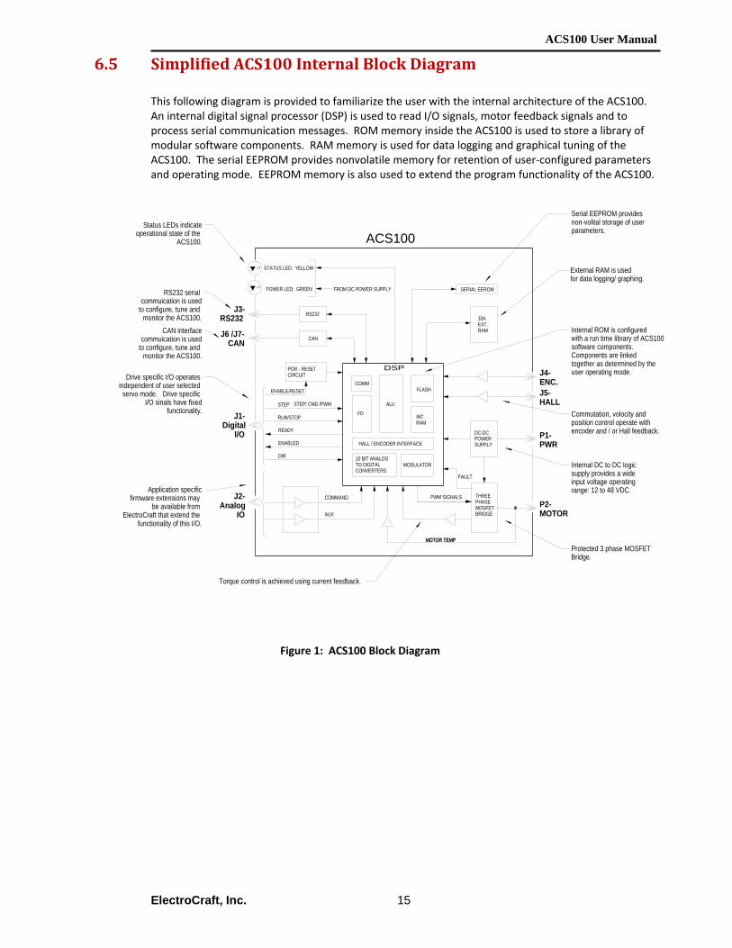
6.5 Simplified ACS100 Internal Block Diagram
This following diagram is provided to familiarize the user with the internal architecture of the ACS100. An internal digital signal processor (DSP) is used to read I/O signals, motor feedback signals and to process serial communication messages. ROM memory inside the ACS100 is used to store a library of modular software components. RAM memory is used for data logging and graphical tuning of the ACS100. The serial EEPROM provides nonvolatile memory for retention of user‐configured parameters and operating mode. EEPROM memory is also used to extend the program functionality of the ACS100.
Figure 1: ACS100 Block Diagram
DSP
FLASH
INT.RAM
MODULATOR
ALU
COMM
THREEPHASEMOSFETBRIDGE
I/O
10 BIT ANALOGTO DIGITALCONVERTERS
RS232
AUX
COMMAND
HALL / ENCODER INTERFACE
PWM SIGNALS
POR - RESETCIRCUIT
SERIAL EEROM
ENABLE/RESET
32KEXT.RAM
DC-DCPOWERSUPPLY
P1-PWR
P2-MOTOR
J5-HALL
J4-ENC.
J2-Analog
IO
J3-RS232
ACS100
Serial EEPROM provides non-volital storage of userparameters.
Internal ROM is configured with a run time library of ACS100software components. Components are linked together as determined by the user operating mode.
Status LEDs indicateoperational state of the
ACS100.
RS232 serial commuication is used
to configure, tune and monitor the ACS100.
Drive specific I/O operates independent of user selected servo mode. Drive specific
I/O sinals have fixedfunctionality.
RUN/STOP
READY
STEP
Commutation, volocity and position control operate with encoder and / or Hall feedback.
Internal DC to DC logic supply provides a wide input voltage operating range: 12 to 48 VDC.
Protected 3 phase MOSFET Bridge.
Torque control is achieved using current feedback.
ENABLED
DIR
J1-Digital
I/O
MOTOR TEMP
CANJ6 /J7-CAN
CAN interfacecommuication is used
to configure, tune and monitor the ACS100.
STATUS LED: YELLOW
POWER LED: GREEN
External RAM is usedfor data logging/ graphing.
STEP/ CMD /PWM
Application specificfirmware extensions may
be available from ElectroCraft that extend the
functionality of this I/O.
MOTOR TEMP
FROM DC POWER SUPPLY
FAULT

ACS100 User Manual
ElectroCraft, Inc.
16
6.6 ACS100 Connector Description Drive specific I/O operates independent of the user selected operating mode. Dive specific I/O signals have fixed functionality. These signals are used to interface the ACS100 to an outside control system. They provide signals for enabling, disabling, and monitoring the status of the ACS100. For visual reference to the ACS100 connectors, see Figure 2 below.
Figure 2: ACS100 Connector Layout
1 2
3 4
1 2 34 5 6
J1
J2
J3
J6
J7
J5 J4
P1 P2JU201JU202
LED 1LED 2
P2 - MOTOR POWER
P1 - DRIVE POWER
J1 - DIGITAL I/O
J5 - MOTOR HALL FEEDBACK
J3: RS-232 INTERFACE
J4 - MOTOR ENCODER FEEDBACK
LED1 - USER POWER
J2 - ANALOG I/O
J6/7 - CAN INTERFACE
LED2 - READY "STATUS"
ACS100-xxxx
ACS100 User Manual
ElectroCraft, Inc.
17
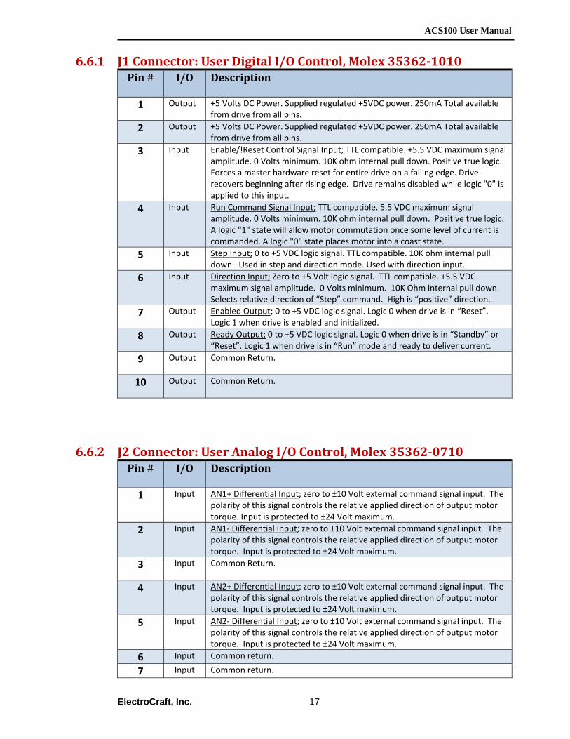
6.6.1 J1 Connector: User Digital I/O Control, Molex 353621010 Pin #
I/O Description
1 Output +5 Volts DC Power. Supplied regulated +5VDC power. 250mA Total available
from drive from all pins.
2 Output +5 Volts DC Power. Supplied regulated +5VDC power. 250mA Total available from drive from all pins.
3 Input Enable/!Reset Control Signal Input; TTL compatible. +5.5 VDC maximum signal amplitude. 0 Volts minimum. 10K ohm internal pull down. Positive true logic. Forces a master hardware reset for entire drive on a falling edge. Drive recovers beginning after rising edge. Drive remains disabled while logic "0" is applied to this input.
4 Input Run Command Signal Input; TTL compatible. 5.5 VDC maximum signal amplitude. 0 Volts minimum. 10K ohm internal pull down. Positive true logic. A logic "1" state will allow motor commutation once some level of current is commanded. A logic "0" state places motor into a coast state.
5 Input Step Input; 0 to +5 VDC logic signal. TTL compatible. 10K ohm internal pulldown. Used in step and direction mode. Used with direction input.
6 Input Direction Input; Zero to +5 Volt logic signal. TTL compatible. +5.5 VDC maximum signal amplitude. 0 Volts minimum. 10K Ohm internal pull down. Selects relative direction of “Step” command. High is “positive” direction.
7 Output Enabled Output; 0 to +5 VDC logic signal. Logic 0 when drive is in “Reset”. Logic 1 when drive is enabled and initialized.
8 Output Ready Output; 0 to +5 VDC logic signal. Logic 0 when drive is in “Standby” or “Reset”. Logic 1 when drive is in “Run” mode and ready to deliver current.
9 Output Common Return.
10 Output Common Return.
6.6.2 J2 Connector: User Analog I/O Control, Molex 353620710 Pin # I/O Description
1 Input AN1+ Differential Input; zero to ±10 Volt external command signal input. The
polarity of this signal controls the relative applied direction of output motor torque. Input is protected to ±24 Volt maximum.
2 Input AN1‐ Differential Input; zero to ±10 Volt external command signal input. The polarity of this signal controls the relative applied direction of output motor torque. Input is protected to ±24 Volt maximum.
3 Input Common Return.
4 Input AN2+ Differential Input; zero to ±10 Volt external command signal input. The polarity of this signal controls the relative applied direction of output motor torque. Input is protected to ±24 Volt maximum.
5 Input AN2‐ Differential Input; zero to ±10 Volt external command signal input. The polarity of this signal controls the relative applied direction of output motor torque. Input is protected to ±24 Volt maximum.
6 Input Common return.
7 Input Common return.
ACS100 User Manual
ElectroCraft, Inc.
18
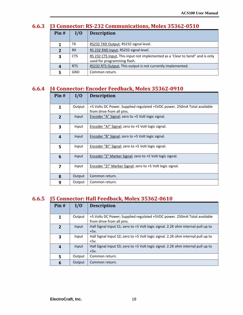
6.6.3 J3 Connector: RS232 Communications, Molex 353620510 Pin # I/O Description
1 TX RS232 TXD Output, RS232 signal level.
2 RX RS 232 RXD Input, RS232 signal level.
3 CTS RS 232 CTS Input, This input not implemented as a ‘Clear to Send” and is only used for programming flash.
4 RTS RS232 RTS Output, This output is not currently implemented.
5 GND Common return.
6.6.4 J4 Connector: Encoder Feedback, Molex 353620910 Pin # I/O Description
1 Output +5 Volts DC Power. Supplied regulated +5VDC power. 250mA Total available
from drive from all pins.
2 Input Encoder "A" Signal; zero to +5 Volt logic signal.
3 Input Encoder "A!" Signal; zero to +5 Volt logic signal.
4 Input Encoder "B" Signal; zero to +5 Volt logic signal.
5 Input Encoder "B!" Signal; zero to +5 Volt logic signal.
6 Input Encoder "Z" Marker Signal; zero to +5 Volt logic signal.
7 Input Encoder "Z!" Marker Signal; zero to +5 Volt logic signal.
8 Output Common return.
9 Output Common return.
6.6.5 J5 Connector: Hall Feedback, Molex 353620610 Pin # I/O Description
1 Output +5 Volts DC Power; Supplied regulated +5VDC power. 250mA Total available
from drive from all pins.
2 Input Hall Signal Input S1; zero to +5 Volt logic signal. 2.2K ohm internal pull up to +5v.
3 Input Hall Signal Input S2; zero to +5 Volt logic signal. 2.2K ohm internal pull up to +5v.
4 Input Hall Signal Input S3; zero to +5 Volt logic signal. 2.2K ohm internal pull up to +5v.
5 Output Common return.
6 Output Common return.
ACS100 User Manual
ElectroCraft, Inc.
19
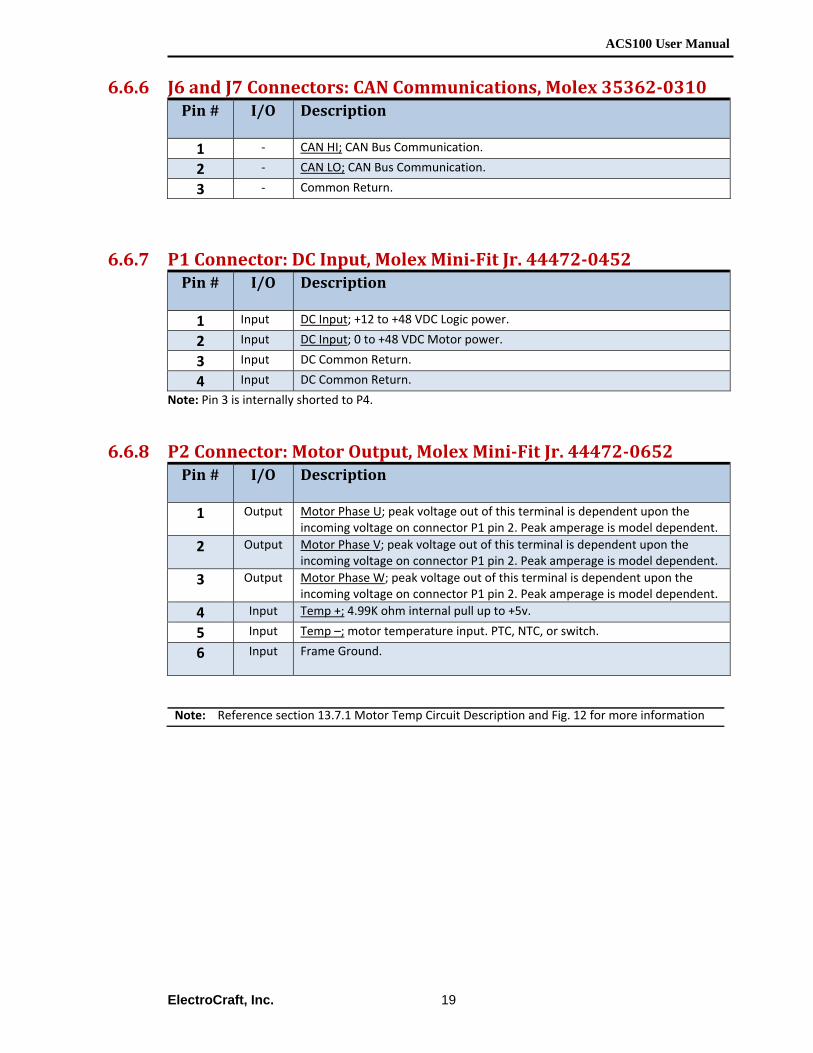
6.6.6 J6 and J7 Connectors: CAN Communications, Molex 353620310 Pin # I/O Description
1 ‐ CAN HI; CAN Bus Communication.
2 ‐ CAN LO; CAN Bus Communication.
3 ‐ Common Return.
6.6.7 P1 Connector: DC Input, Molex MiniFit Jr. 444720452 Pin # I/O Description
1 Input DC Input; +12 to +48 VDC Logic power.
2 Input DC Input; 0 to +48 VDC Motor power.
3 Input DC Common Return.
4 Input DC Common Return.
Note: Pin 3 is internally shorted to P4.
6.6.8 P2 Connector: Motor Output, Molex MiniFit Jr. 444720652 Pin # I/O Description
1 Output Motor Phase U; peak voltage out of this terminal is dependent upon the
incoming voltage on connector P1 pin 2. Peak amperage is model dependent.
2 Output Motor Phase V; peak voltage out of this terminal is dependent upon the incoming voltage on connector P1 pin 2. Peak amperage is model dependent.
3 Output Motor Phase W; peak voltage out of this terminal is dependent upon the incoming voltage on connector P1 pin 2. Peak amperage is model dependent.
4 Input Temp +; 4.99K ohm internal pull up to +5v.
5 Input Temp –; motor temperature input. PTC, NTC, or switch.
6 Input Frame Ground.
Note: Reference section 13.7.1 Motor Temp Circuit Description and Fig. 12 for more information
ACS100 User Manual
ElectroCraft, Inc.
20
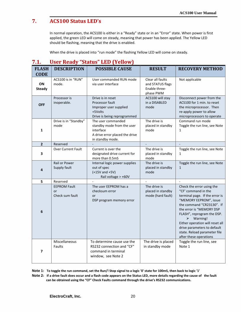
7. ACS100 Status LED’s In normal operation, the ACS100 is either in a “Ready” state or in an “Error” state. When power is first applied, the green LED will come on steady, meaning that power has been applied. The Yellow LED should be flashing, meaning that the drive is enabled. When the drive is placed into “run mode” the flashing Yellow LED will come on steady.
7.1. User Ready “Status” LED (Yellow) FLASH CODE
DESCRIPTION POSSIBLE CAUSE RESULT RECOVERY METHOD
ON Steady
ACS100 is in “RUN” mode.
User commanded RUN mode via user interface
Clear all faults and STATUS flags Enable three‐phase PWM
Not applicable
OFF
Processor is inoperable.
Drive is in reset Processor fault Improper user supplied +5Volts Drive is being reprogrammed
ACS100 will stay in a DISABLED mode
Disconnect power from the ACS100 for 1 min. to reset the microprocessor. Then re‐apply power to allow microprocessors to operate
1
Drive is in “Standby” mode
The user commanded standby mode from the user interface A drive error placed the drive in standby mode.
The drive is placed in standby mode
Command run mode Toggle the run line, see Note 1
2 Reserved ‐ ‐ ‐
3 Over Current Fault Current is over the
designated drive current for more than 0.5mS
The drive is placed in standby mode
Toggle the run line, see Note 1
4
Rail or Power Supply fault
Internal logic power supplies out of spec (+15V and +5V)
Rail voltage > +60V
The drive is placed in standby mode
Toggle the run line, see Note 1
5 Reserved ‐ ‐ ‐
6
EEPROM Fault or Check sum fault
The user EEPROM has a checksum error or DSP program memory error
The drive is placed in standby mode (hard fault)
Check the error using the “CF’ command in the terminal page. If the error is “MEMORY EEPROM”, issue the command “CR23130”. If the error is “MEMORY DSP FLASH”, reprogram the DSP.
Warning! Either operation will reset all drive parameters to default state. Reload parameter file after these operations
7
Miscellaneous Faults
To determine cause use the RS232 connection and “CF” command in terminal window, see Note 2
The drive is placed in standby mode
Toggle the run line, see Note 1
Note 1: To toggle the run command, set the Run/! Stop signal to a logic '0' state for 100mS, then back to logic '1' Note 2: If a drive fault does occur and a flash code appears on the Status LED, more details regarding the cause of the fault
can be obtained using the “CF” Check Faults command through the drive’s RS232 communications.

ACS100 User Manual
ElectroCraft, Inc.
21
7.2. User Power LED (Green) LED Description Possible Cause Result Recovery Method
ON
+5 VDC Power Indicator
• On if user power is on
• Required to Run
• N/A
OFF +5 VDC Power Indicator
• No logic power • Drive will not Run
• Apply +12 – 48VDC
DIM +5 VDC Power Indicator
• Logic voltage input to low
• Drive may not run properly
• Apply +12VDC minimum
The remainder of this page is intentionally left blank.

ACS100 User Manual
ElectroCraft, Inc.
22
8. Introduction to ElectroCraft CompletePower™ Plus Software
ElectroCraft CompletePower™ Plus is a Windows® ‐based program used for setup, parameterization, system diagnostics and motion control management. ElectroCraft CompletePower™ Plus will lead the user through an 8‐Step Wizard to create the correct parameter configuration and information required for the user to run a particular motor with a particular drive. The result will be an “Application” containing all of the parameter information required to run the motor with the drive. This section is described within the software user manual: ElectroCraft CompletePower™ Plus software users manual. Please refer to the user’s manual for full documentation support to properly configure and operate your drive. Windows® is a registered trademark of the Microsoft Corporation.
The remainder of this page is intentionally left blank.
ACS100 User Manual
ElectroCraft, Inc.
23
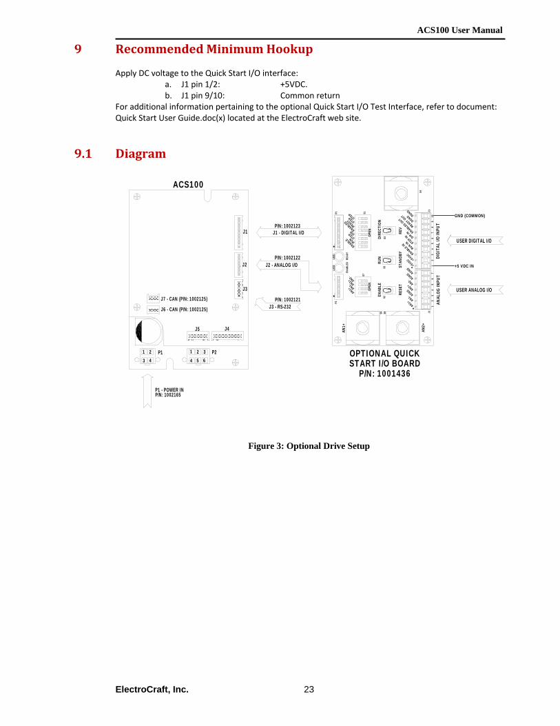
9 Recommended Minimum Hookup Apply DC voltage to the Quick Start I/O interface:
a. J1 pin 1/2: +5VDC. b. J1 pin 9/10: Common return
For additional information pertaining to the optional Quick Start I/O Test Interface, refer to document: Quick Start User Guide.doc(x) located at the ElectroCraft web site.
9.1 Diagram
Figure 3: Optional Drive Setup
J6 - CAN (P/N: 1002125)
J2
J3
J4J5
P2P11 23 4
1 2 34 5 6
J1
J7 - CAN (P/N: 1002125)
J1 - DIGITAL I/O
J2 - ANALOG I/O
P/N: 1002123
P/N: 1002122
P/N: 1002121J3 - RS-232
P1 - POWER INP/N: 1002165
+5 VDC IN
GND (COMMON)
S2S5
S3
P1
J1
S1S7
P2
S4
S6 S8 J2
OPEN
OPEN
OPTIONAL QUICKSTART I/O BOARD
P/N: 1001436
DIGI
TAL
I/O IN
PUT
ANAL
OG IN
PUT
USER DIGITAL I/O
USER ANALOG I/O
12
3
AN1-
45
AN1-
71
24
6STEP
89
READY
10DGND
RUN
AN2+
6
AN1+
AN2+AN2-
AGND
RESE
T
AN1+AN2+ AN2-
35
7
DIR IN
STEP IN
RUN IN
STAN
DBY
ENABLE RUNDIR
READ
YEN
ABLE
D
DGNDSTEP STEP
AN1+
ENAB
LE
+5VDC
+5VDC
ENABLE IN
AGND AGND
READY OUT
ENABLED OUT
DIRE
CTIO
N
ENABLED
REV
LED2
LED1
ACS100
ACS100 User Manual
ElectroCraft, Inc.
24
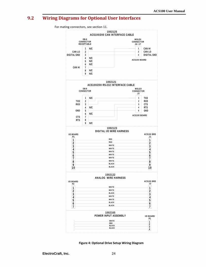
9.2 Wiring Diagrams for Optional User Interfaces
For mating connectors, see section 11.
Figure 4: Optional Drive Setup Wiring Diagram
123
MOLEXCONNECTOR
J6 / J7
DB-9CONNECTORRECEPTABLE
N/CCAN LO
3N/C
N/CCAN HI
89
CAN HI
DIGITAL GNDCAN LO
4567
12
DIGITAL GND
N/CN/C
N/C
WHITE
RED
BLACKBLACK
REDWHITE
WHITE
WHITEWHITE
3
12
4
65
7
98
10
WHITE3
12
4
65
7
98
10
3
12
4
65
7
3
12
4
65
7BLACKBLACK
WHITE
WHITE
BLACKWHITE
WHITE
1002122ANALOG WIRE HARNESS
1002123DIGITAL I/O WIRE HARNESS
12345
MOLEXCONNECTOR
J3
DB-9CONNECTOR
N/CTXD
3N/C
GNDN/C
CTS89
ACS100 BOARD
TXD
CTSRTS
RXD
GND4567
12
RXD
RTSN/C
3
WHITERED 1
2
4BLACKBLACK
ACS100 BOARD
ACS100 BRDJ1
I/O BOARDP1
ACS100 BRDJ2
I/O BOARDP2
1002165POWER INPUT ASSEMBLY I/O BOARD
P1
1002125ACS100/200 CAN INTERFACE CABLE
1002121ACS100/200 RS-232 INTERFACE CABLE

ACS100 User Manual
ElectroCraft, Inc.
25
10 First Time Operation
10.1 Phasing the Motor ElectroCraft has determined the correct motor phasing for all ElectroCraft motors. If your drive was ordered with an ElectroCraft motor specified, the correct parameter set for the mating ElectroCraft motor was loaded into your drive at the factory prior to shipment. Alternate ElectroCraft motor parameters can be selected from the motor selection file on the software disk supplied with your drive, or you can contact ElectroCraft for these files. In addition, ElectroCraft has established the correct motor phasing relationships for many other popular US and foreign motor manufacturers. A listing of these additional motor manufacturers may be obtained from ElectroCraft upon request.
10.2 Using ElectroCraft CompletePower™ Plus
To establish the correct motor phasing for a new or unknown motor ElectroCraft has provided a Window based setup utility. Please refer to the ElectroCraft CompletePower™ Plus software user manual to setup your drive and analyze the performance of the drive as well as the motor. Getting Started To make use of this feature proceed as follows:
1. Install ElectroCraft CompletePower™ Plus software onto user PC. 2. Connect all phase and hall wires to the drive. 3. Place drive into standby 4. Connect power and establish communications 5. Load a starting parameter set (Use default supplied in drive, user saved parameter set, or
contact ElectroCraft for assistance) 6. The motor should now be properly phased for the ACS100. You can now proceed with drive
loop tuning.
ACS100 User Manual
ElectroCraft, Inc.
26
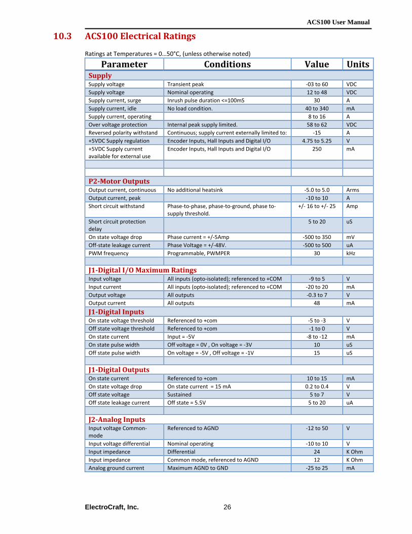
10.3 ACS100 Electrical Ratings
Ratings at Temperatures = 0…50°C, (unless otherwise noted)
Parameter Conditions Value Units Supply Supply voltage Transient peak ‐03 to 60 VDC Supply voltage Nominal operating 12 to 48 VDC Supply current, surge Inrush pulse duration <=100mS 30 A Supply current, idle No load condition. 40 to 340 mA Supply current, operating 8 to 16 A Over voltage protection Internal peak supply limited. 58 to 62 VDC Reversed polarity withstand Continuous; supply current externally limited to: ‐15 A +5VDC Supply regulation Encoder Inputs, Hall Inputs and Digital I/O 4.75 to 5.25 V +5VDC Supply current available for external use
Encoder Inputs, Hall Inputs and Digital I/O 250 mA
P2Motor Outputs Output current, continuous No additional heatsink ‐5.0 to 5.0 Arms Output current, peak ‐10 to 10 A Short circuit withstand Phase‐to‐phase, phase‐to‐ground, phase to‐
supply threshold. +/‐ 16 to +/‐ 25 Amp
Short circuit protection delay
5 to 20 uS
On state voltage drop Phase current = +/‐5Amp ‐500 to 350 mV Off‐state leakage current Phase Voltage = +/‐48V. ‐500 to 500 uA PWM frequency Programmable, PWMPER 30 kHz
J1Digital I/O Maximum Ratings Input voltage All inputs (opto‐isolated); referenced to +COM ‐9 to 5 V Input current All inputs (opto‐isolated); referenced to +COM ‐20 to 20 mA Output voltage All outputs ‐0.3 to 7 V Output current All outputs 48 mA
J1Digital Inputs On state voltage threshold Referenced to +com ‐5 to ‐3 V Off state voltage threshold Referenced to +com ‐1 to 0 V On state current Input = ‐5V ‐8 to ‐12 mA On state pulse width Off voltage = 0V , On voltage = ‐3V 10 uS Off state pulse width On voltage = ‐5V , Off voltage = ‐1V 15 uS
J1Digital Outputs On state current Referenced to +com 10 to 15 mA On state voltage drop On state current = 15 mA 0.2 to 0.4 V Off state voltage Sustained 5 to 7 V Off state leakage current Off state = 5.5V 5 to 20 uA
J2Analog Inputs Input voltage Common‐mode
Referenced to AGND ‐12 to 50 V
Input voltage differential Nominal operating ‐10 to 10 V Input impedance Differential 24 K Ohm Input impedance Common mode, referenced to AGND 12 K Ohm Analog ground current Maximum AGND to GND ‐25 to 25 mA
ACS100 User Manual
ElectroCraft, Inc.
27
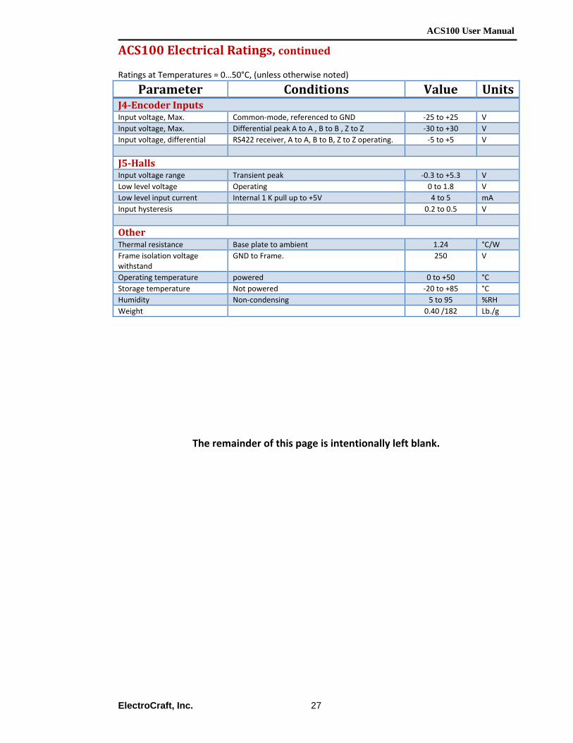
ACS100 Electrical Ratings, continued Ratings at Temperatures = 0…50°C, (unless otherwise noted)
Parameter Conditions Value Units J4Encoder Inputs Input voltage, Max. Common‐mode, referenced to GND ‐25 to +25 V Input voltage, Max. Differential peak A to A , B to B , Z to Z ‐30 to +30 V Input voltage, differential RS422 receiver, A to A, B to B, Z to Z operating. ‐5 to +5 V
J5Halls Input voltage range Transient peak ‐0.3 to +5.3 V Low level voltage Operating 0 to 1.8 V Low level input current Internal 1 K pull up to +5V 4 to 5 mA Input hysteresis 0.2 to 0.5 V
Other Thermal resistance Base plate to ambient 1.24 °C/W Frame isolation voltage withstand
GND to Frame. 250 V
Operating temperature powered 0 to +50 °C Storage temperature Not powered ‐20 to +85 °C Humidity Non‐condensing 5 to 95 %RH Weight 0.40 /182 Lb./g
The remainder of this page is intentionally left blank.
ACS100 User Manual
ElectroCraft, Inc.
28
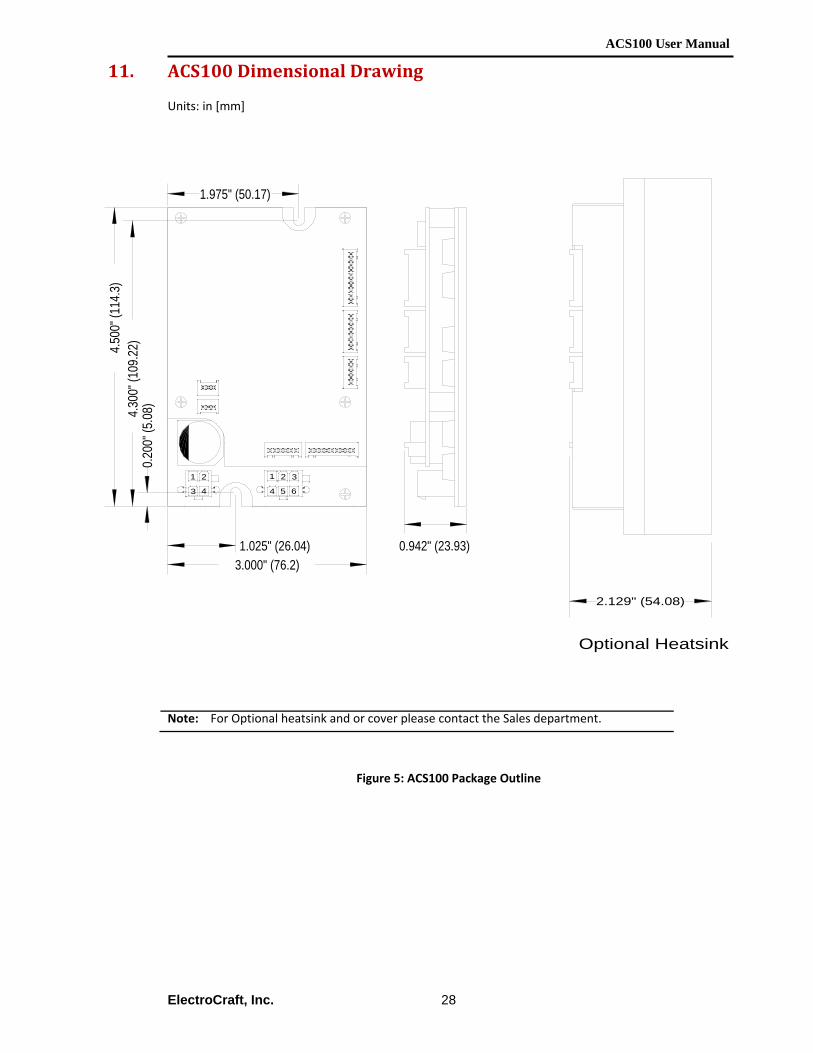
11. ACS100 Dimensional Drawing Units: in [mm]
Figure 5: ACS100 Package Outline
Note: For Optional heatsink and or cover please contact the Sales department.
1 2
3 4
1 2 3
4 5 6
1.025" (26.04)3.000" (76.2)
0.20
0" (5
.08)4.30
0" (1
09.2
2)4.50
0" (1
14.3
)
1.975" (50.17)
0.942" (23.93)
Optional Heatsink
2.129" (54.08)

ACS100 User Manual
ElectroCraft, Inc.
29
12. List of Mating Connectors
Ref. Connector Name
Manufacturer P/N P/N Crimp Pin
J1 User Digital I/O Control
10 Pin Molex Sherlock 35507-1000 50212-8100
J2 User Analog I/O Control
7 Pin Molex Sherlock 35507-0700 50212-8100
J3 RS232 Communications
5 Pin Molex Sherlock 35507-0500 50212-8100
J4 Encoder Interface
9 Pin Molex Sherlock 35507-0900 50212-8100
J5 Hall Interface
6 Pin Molex Sherlock 35507-0600 50212-8100
J6 & J7 CAN Communications
3 Pin Molex Sherlock 35507-0300 50212-8100
P1 DC Input 4 Pin Molex Mini-Fit Jr. 3901-3042 5556 or 44476(HC)
P2 Motor Output 6 Pin Molex Sherlock 3901-2060 5556 or 44476(HC)
The remainder of this page is intentionally left blank.
ACS100 User Manual
ElectroCraft, Inc.
30
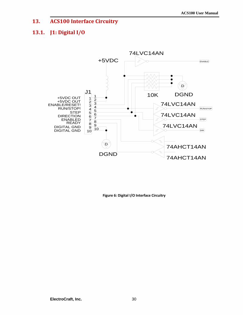
13. ACS100 Interface Circuitry
13.1. J1: Digital I/O
Figure 6: Digital I/O Interface Circuitry
DIR
STEP
RUN/STOP
+5VDC
D
DGND
ENABLE
D
DGND
88
55
22
77
44
11
99
66
33
1010
J1
74LVC14AN
74AHCT14AN
74LVC14AN
74LVC14AN
74LVC14AN
74AHCT14AN
10K
DIGITAL GND
READYENABLED
STEPRUN/STOP!
+5VDC OUT+5VDC OUT
DIGITAL GND
DIRECTION
ENABLE/RESET!

ACS100 User Manual
ElectroCraft, Inc.
31
13.2. J2: Analog I/O
Figure 7: Analog I/O Interface Circuitry
A
AGND
16.9K
6.8K
6.8K
16.9K
6.8K
2.10K
BAW56
+5VDC
BAV70
BAW56
+5VDC
BAV70
8.45K
27pF
27pF
8.45K
6.8K
2.10K
TLE2142CD
+3.3VDC
6.8K
16.9K
6.8K
+3.3VDC
16.9K
6.8K
77
44
11
55 66
22 33
J2
A AGND
TLE2142CD
6.8K
AAGND
AGNDAN2-
AGNDAN1-
AGND
AN2+
AN1+
ACS100 User Manual
ElectroCraft, Inc.
32
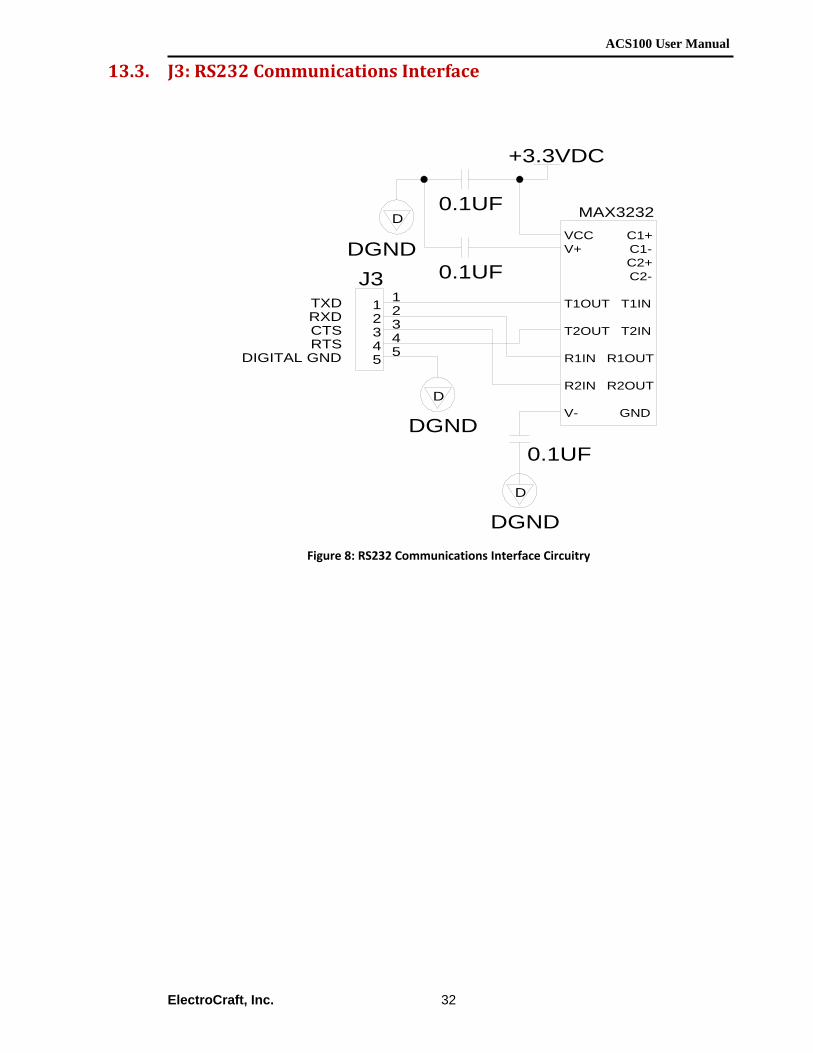
13.3. J3: RS232 Communications Interface
Figure 8: RS232 Communications Interface Circuitry
3355
2244
11
J3
+3.3VDC
D
DGND
D
DGND
D
DGND
0.1UF
0.1UF
0.1UFVCCV+
T1OUT
T2OUT
R1IN
R2IN
V- GND
R2OUT
R1OUT
T2IN
T1IN
C2-
C1-C1+
C2+
MAX3232
RTS
RXDTXD
CTS
DIGITAL GND
ACS100 User Manual
ElectroCraft, Inc.
33
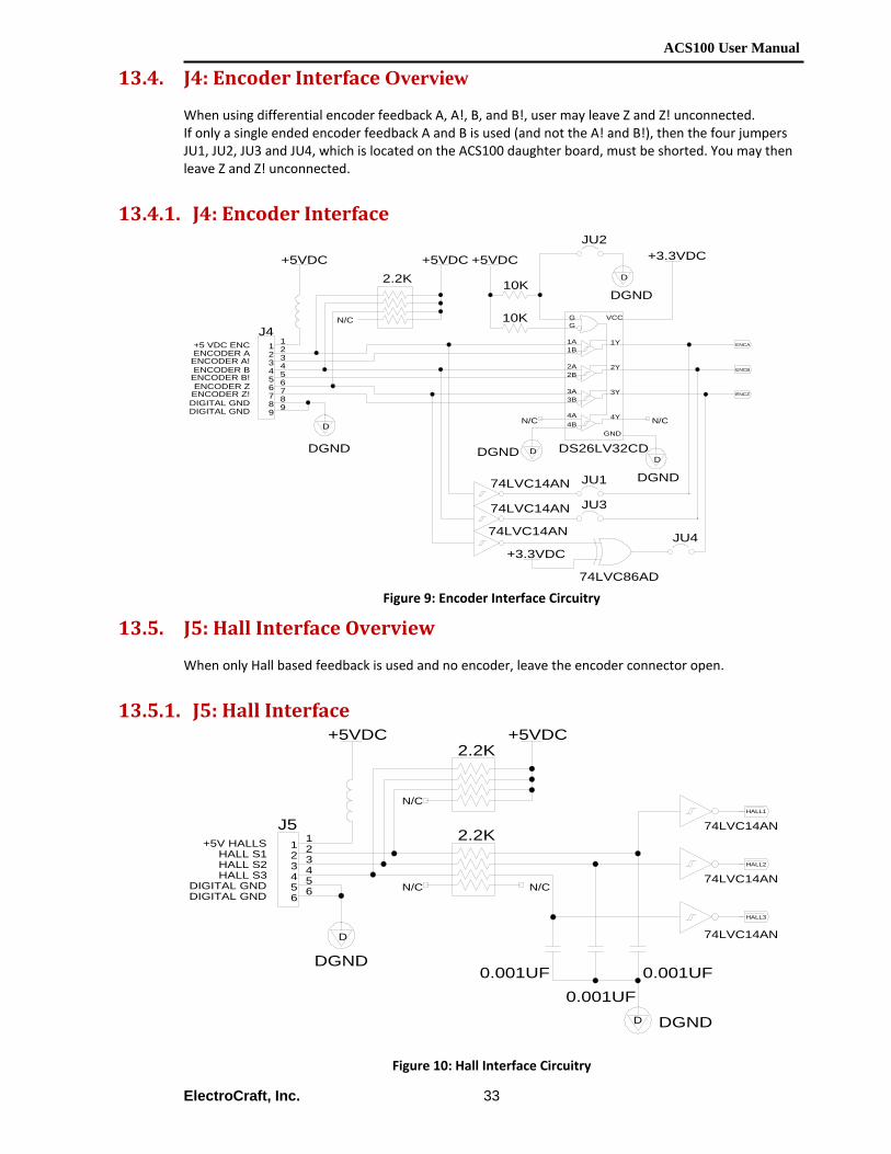
13.4. J4: Encoder Interface Overview When using differential encoder feedback A, A!, B, and B!, user may leave Z and Z! unconnected. If only a single ended encoder feedback A and B is used (and not the A! and B!), then the four jumpers JU1, JU2, JU3 and JU4, which is located on the ACS100 daughter board, must be shorted. You may then leave Z and Z! unconnected.
13.4.1. J4: Encoder Interface
Figure 9: Encoder Interface Circuitry
13.5. J5: Hall Interface Overview When only Hall based feedback is used and no encoder, leave the encoder connector open.
13.5.1. J5: Hall Interface
Figure 10: Hall Interface Circuitry
+5VDC
+3.3VDC
10K
D
DGND
D
DGND
ENCA
ENCZ
ENCB
D
DGND DDGND
10K
+5VDC
74LVC86AD
74LVC14AN
JU3
JU1
+3.3VDC+5VDC2.2K
88
55
22
77
44
11
66
33
99
J4
4A4B
3A3B
2A2B
1A1B
GG
GND
4Y
3Y
2Y
1Y
VCC
DS26LV32CD
JU4
74LVC14AN
74LVC14AN
JU2
N/CDIGITAL GNDDIGITAL GND
ENCODER ZENCODER B!
ENCODER A!ENCODER A
ENCODER Z!
ENCODER B
+5 VDC ENC
N/C
N/C
HALL3
HALL1
D
DGND0.001UF
HALL2
+5VDC +5VDC
D DGND
0.001UF0.001UF
74LVC14AN
74LVC14AN
44
11
55 66
22 33
J52.2K
2.2K
74LVC14ANN/C N/C
N/C
HALL S3DIGITAL GND
+5V HALLSHALL S1
DIGITAL GND
HALL S2
ACS100 User Manual
ElectroCraft, Inc.
34
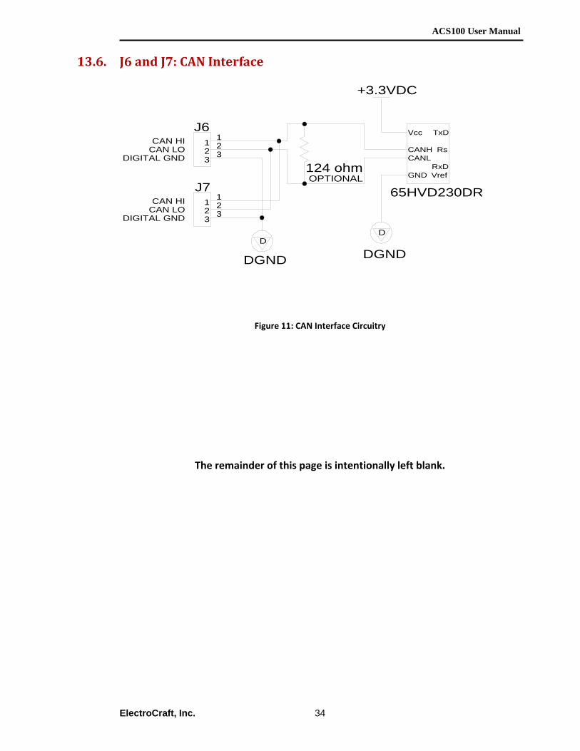
13.6. J6 and J7: CAN Interface
Figure 11: CAN Interface Circuitry
The remainder of this page is intentionally left blank.
11 22 33
J6
124 ohm
11 22 33
J7
D
DGND
D
DGND
+3.3VDC
Vcc
CANHCANL
GND VrefRxD
Rs
TxD
65HVD230DROPTIONAL
DIGITAL GND
CAN HI
CAN LOCAN HI
CAN LO
DIGITAL GND
ACS100 User Manual
ElectroCraft, Inc.
35
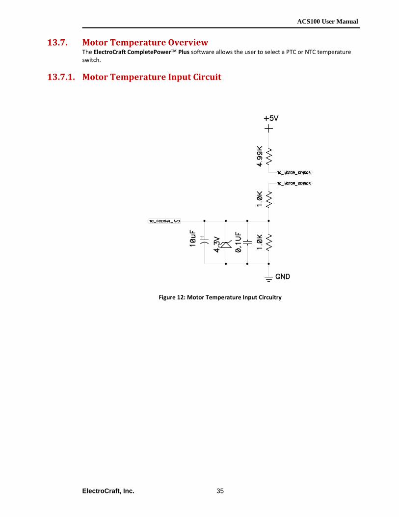
13.7. Motor Temperature Overview
The ElectroCraft CompletePower™ Plus software allows the user to select a PTC or NTC temperature switch.
13.7.1. Motor Temperature Input Circuit
Figure 12: Motor Temperature Input Circuitry

14.
14.1.
ElectroCra
Externa
Use and
CAUWHEN THMUST BE Never mouliquid and/any type, inmaterials th
THIS PROUSER.
Shunt resiswhenever tthe precautfire hazard.may be pre In most apACS100 wiloptional AC
aft, Inc.
al Shunt
d Selectio
UTIONHIS PRODUE FOLLOWE
unt the extern/or flammable n an explosivehat could melt
ODUCT USE
tors function uthe ACS100 hation statemen. The electricaesent on these
pplications whll require an eCS100 Shunt bo
Figure 13:
on of the O
N! UCT USES THED TO PREV
nal shunt whechemicals. Ne atmosphere.t or drop upon
ES ELECTRIC
using high voltas power applits, and in conjl terminals of terminals whe
hen heavy dynexternal shuntoard. See Figur
36
Optional Shu
Optional S
HE OPTIONVENT A POS
ere it can makever use the A. Never place n the shunt res
C POWER A
tage electric poed. Shunt resijunction with tshunt resistorenever the AC
namic brakingt resistor. To re 13 above.
nt Assembly
Shunt Ass
AL SHUNT SSIBLE FIRE
ke contact witACS100, eitherthe shunt ressistor body or t
AND POSES
ower. Avoid pistor(s) can alsthe manufactus are also a shCS100 has pow
g and/or regeconnect such
A
sembly
ASSEMBLYHAZARD.
th flammable r with or withosistor in the prthe ACS100 dr
A SHOCK H
physical contacso become extures precautioock hazard. H
wer applied.
enerative braka resistor req
ACS100 User
Y, PRECAUT
materials, flaout a shunt reroximity of flarive.
HAZARD TO
ct with them tremely hot. Fns, to help preHigh voltage ele
king are involvquires the use
Manual
TIONS
mmable sistor of mmable
THE
Follow event a ectricity
ved, the e of the

ACS100 User Manual
ElectroCraft, Inc.
37
The minimum permissible combined resistance value for the shunt resistor(s) is 4 Ohms. Higher resistance values may be used. The resistor(s) should be rated for high momentary overloads. The External Shunt Board is supplied with a 40 watt / 50 ohm shunt resistor. When the ACS100 shunt board is used it is wired between the P1 DC Input connector and the DC power source. Please refer to section 6.6.7 for connector wiring. The optional ACS100 shunt board operates in conjunction with a transistor switch that places the resistor(s) across the DC power rail. Should the transistor ever fail in the ON condition the resistor would remain powered continuously. This could result in the shunt resistor becoming very hot. The selected wattage rating for the shunt resistor is application dependent. Usually a heavy‐duty wire wound resistor will work best. However, not all wire wound resistors are suitable for shunt service. ElectroCraft has found the Ohmite type 250 series works reliably in many shunt applications. If the user is supplying their own shunt resistor contact ElectroCraft for further application advice. Ask for Field Application Bulletin #101‐0195.
14.2. Connecting the Optional Shunt Board The shunt board is designed to plug directly between the ACS100 and the users power supply. To install, plug a cable (Part No. 1001734) from the power supply directly into P1 on the shunt board. Then plug cable (Part No. 1001730) from P2 of the optional shunt board to P1 of the ACS100. Both P1 and P2 connectors, of the optional shunt board, have the same pin out. Shunt Board: P1 ‐ Power input from Power Supply. P2 ‐ Power output to ACS100.
Pin1: +12v to +48v drive logic supply (pass through connection from P1 to P2). Pin2: 0 to +48v drive motor supply.
(Blocking diode at P1 isolates all shunt board operations from power supply). Pin3: Drive logic supply common (pass through connection from P1 to P2). Pin4: Motor supply common (pass through connection from P1 to P2).
The shunt “turn‐on” threshold is approximately 56V and the “turn‐off” threshold is approximately 52V. A blocking diode in the shunt board prevents the excess voltage from feeding back to the power supply. As the drive “regenerates”, the shunt board will cycle on and off to dispose of the excess energy through the shunt resistor. Care should be taken to ensure the shunt resistor is not mounted next to any flammable material, as it could get hot.
Note: If the ACS100 is setup to operate from a single supply for both logic and motor, only the motor supply (pins 2 and 4) need to be connected.
ACS100 User Manual
ElectroCraft, Inc.
38
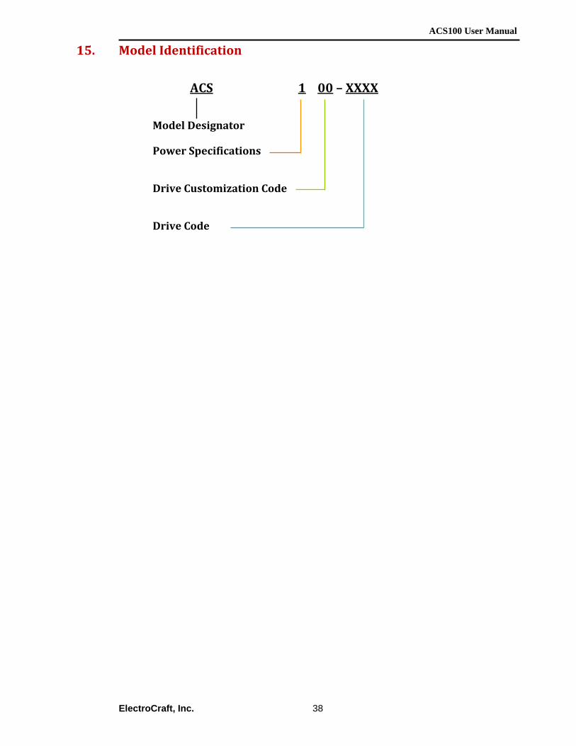
15. Model Identification
ACS 1 00 – XXXX
Model Designator
Power Specifications Drive Customization Code Drive Code
ACS100 User Manual
ElectroCraft, Inc.
39
16. Appendix A Optional Accessories
Name Length mm (inch)
Description Part No.
ACS100/200 Mating connectors and cable Kit
(305mm(12”)
ACS100/200 (7 cable assembly) to wire ends: Loose wires at user end.
1002115
Quick‐Start I/O Test Board
108 x 65 x 36mm
(4.25 x 2.5 x 1.4”)
(W x H x D)
Test Board
1001436
1002999 (set)
Quick Start to ACS100/200 Digital I/O Cable
305mm(12”)
Quick Start Test Board P1 to ACS100 J1.
1002119 Quick Start to ACS100/200 Analog I/O Cable
305mm(12”)
Quick Start Test Board P2 to ACS100 J2.
RS232 Interface Cable (Interface cable for PC)
356mm(14”)
D‐sub 9 pin plug to ACS100 J3.1
1002121
Motor Interface Test Board
96 x 65 x 21mm
(3.8 x 2.5 x 0.83”)
(W x H x D
Test Board used to easily wire motor to the ACS100 drive.
1001732
Hall Cable 305mm(12”)
Interface board J3 to ACS100 J5.
1002112
Encoder Cable 305mm(12”)
Interface board J2 to ACS100 J4.
1002113
Motor Phase Cable 356mm(14”)
Interface board J1 to ACS100 P2.
1002118
Power Input Cable 356mm(14”)
Interface board J1 to ACS100 P2.
1002165
1
S6
11
MOTOR INTERFACE BOARD
11
1
4123
ACS100 User Manual
ElectroCraft, Inc.
40
Note: Custom lengths or applications may be ordered.
Name Length inch (mm)
Description Part No.
ACS to R/D or Dual Encoder Interface Cable
356mm(14”)
D‐sub 15 pin to ACS100 J4. Used with R/D or Dual Encoder option boards.
1
1002129
ACS Connector Board 76.20 x 99.06mm 3.0 x 3.9”
Adapter Board with spring terminals to easily wire perifual devices to the ACS100 drive.
1001203
Can Interface – Wire ends
305mm(12”)
Loose wires at user end to ACS100 J6/J7.
1002159
CAN Interface – DB9F (Interface cable for PC)
356mm(14”)
D‐sub 9 pin Plug to ACS100 J6/J7.
1002125
CAN Terminating Resistor
n/a 120 ohm resistor between ACS100 J6/J7 pins 1 and 2.
1002127
Shunt Board Assembly 114.3 x 64 x 35.56 mm (4.5 x 2.5 x 1.40”) (W x H x D)
External Shunt Board
1001193
1002991 (set)
Shunt Board wire harness assemblies
356mm(14”)
Shunt board P2 to ACS100 P1.
1001730
356mm(14”)
Shunt board P1 to user supply: Loose wires at user end.
1002165
P6: CAN
PCB S/N
PCB Rev. 0
P3: RS232
Sub-Asm # 100
PCB Part # 320216
P5: HALLS
P2: ANALOG I/O
P1: DIGITAL I/O
P4: ENCODER
1
1
1
1
4123
4123