acuta standard gps antenna - digikey
TRANSCRIPT

Integrated Antenna and RF Solutions
1 Product Specification 11MD-0041-2-PS
Acuta Standard GPS Antenna Part No. A10415 Product Specification
1 Features • GPS antenna designed for embedded applications • Small size and light weight (0.5g) • High performance • Upward hemispherical RHCP pattern • Simple matching circuit tuning • Works in many different positions in the device • No extra mechanical support required 2 Description Acuta GPS antenna is an innovative high performance GPS antenna designed to replace ceramic patch antennas, reduce development costs and improve time-to-market – all without compromising performance. The very slim A10415 allows a substantial reduction in the minimum thickness of the host device compared to a solution using a 12x12mm² ceramic patch antenna. Acuta is intended to be mounted at the edge of the host PCB facing the sky, in a similar way to a conventional patch antenna, which generates an almost hemispherical radiation pattern towards the sky - achieving optimal GPS performance. Acuta GPS antenna is intended for reception of GPS signals at 1575 MHz and is easily tuned using a simple matching circuit on the host PCB, allowing the same antenna to be used in different devices without physical modifications. The antenna is soldered directly onto the host PCB, without the need of expensive coaxial cables, RF connectors or mounting frames, significantly reducing the total BOM of the GPS solution. The antenna uses a ground plane in order to radiate efficiently, which should be at least 30 x 30 mm. 3 Applications • Portable Navigation Devices (PNDs) • GPS Trackers • Mobile phones/ Smart phones • Notebooks / Tablets / eReaders • M2M

Acuta Standard GPS Antenna Part No. A10415
4 Part number Acuta: A10415
(Bottom View)
5 General data
Product name Acuta
Part Number A10415
Frequency GPS - 1575 MHz
Polarization Linear
Operating temperature -40 ºC to +85 ºC
Impedance with matching 50 Ω
Weight 0.5 g
Antenna type Metal
Dimensions (LxWxH) 25.0 x 5.0 x 4.3 [mm] (Effective) 29.6 x 5.0 x 6.8 [mm] (Total)
6 Electrical characteristics
Typical performance Reference Board A10415-U1 Conditions
Bandwidth (Typical) 30 MHz at –10 dB Return Loss
Peak gain (Linear) +0.4 dB
Average gain (Linear) -2.2 dB
Average efficiency (Linear) 60%
Peak gain (RHCP) -1.0 dB
Average gain (RHCP) -3.9dB
Average efficiency (RHCP) 40%
Maximum Return Loss -10 dB
Maximum VSWR 2:1
All data measured on Antenova’s reference board, part number
A10415-U1
Data given for the 1573.42 – 1577.42 MHz
frequency range
Integrated Antenna and RF Solutions 2
Product Specification 11MD-0041-2-PS
Acuta Standard GPS Antenna Part No. A10415
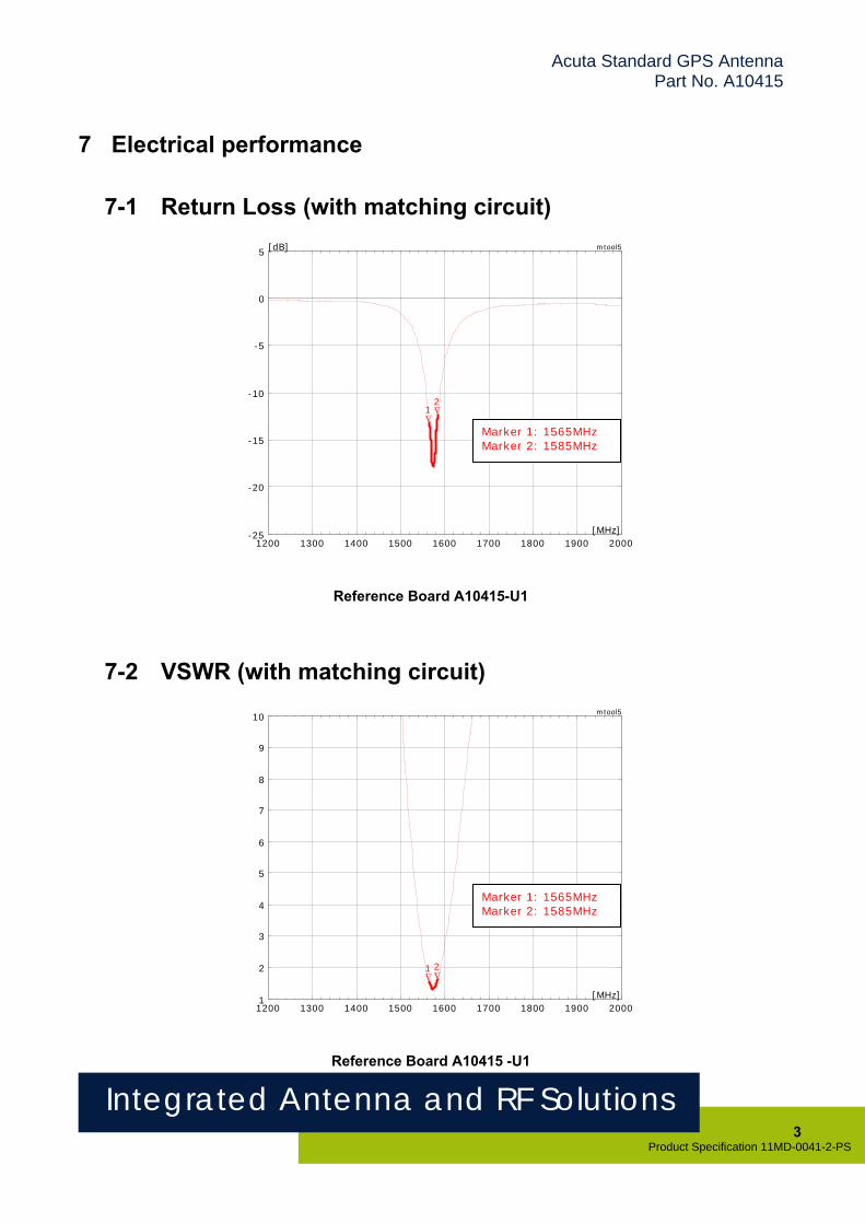
7 Electrical performance
7-1 Return Loss (with matching circuit)
Integrated Antenna and RF Solutions 3
Product Specification 11MD-0041-2-PS
1200 1300 1400 1500 1600 1700 1800 1900 2000
-25
-20
-15
-10
-5
0
5
∇ 1
∇ 2
[MHz]
[dB] mtool5
Marker 1: 1565MHz Marker 2: 1585MHz
Reference Board A10415-U1
7-2 VSWR (with matching circuit)
1200 1300 1400 1500 1600 1700 1800 1900 20001
2
3
4
5
6
7
8
9
10
∇ 1
∇ 2
[MHz]
mtool5
Marker 1: 1565MHz Marker 2: 1585MHz
Reference Board A10415 -U1

Acuta Standard GPS Antenna Part No. A10415
7-3 Antenna patterns 1575MHz
A10415-U1 Ref Board
TOTAL (RHCP+LHCP) RHCP ONLY
Integrated Antenna and RF Solutions 4
Product Specification 11MD-0041-2-PS
-35 -25 -15 -5 5
0°
90°
180°
270°
Radial Scale: dBi
XY Plane

Acuta Standard GPS Antenna Part No. A10415
TOTAL (RHCP+LHCP) RHCP ONLY
-35 -25 -15 -5 5
0°
90°
Integrated Antenna and RF Solutions 5
Product Specification 11MD-0041-2-PS
-35 -25 -15 -5 5
0°
90°
180°
270°
Radial Scale: dBi
180°
270°
Radial Scale: dBi
ZY Plane
TOTAL (RHCP+LHCP) RHCP ONLY
XZ Plane

Acuta Standard GPS Antenna Part No. A10415
8 Antenna dimensions
Front View Side View
L1 L2 W H1 H2 H3
Length1 Length2 Width Height1 Height2 Height3
29.6. ± 0.2 25.0 ± 0.2 5.0 ± 0.2 6.8 ± 0.15 4.0 ± 0.15 0.3 ± 0.1
Dimensions in mm
Integrated Antenna and RF Solutions 6
Product Specification 11MD-0041-2-PS

Acuta Standard GPS Antenna Part No. A10415
9 Antenna footprint GPS Antenna (Part No: A10415)
Integrated Antenna and RF Solutions 7
Product Specification 11MD-0041-2-PS
A B C D E F G J K M
1.4 1.2 5.1 19.5 0.8 23.9 0.3 2.0 0.2 1.5
Dimensions in mm. Tolerances for all dimensions on this table are ± 0.1 mm.
* CAD files of the antenna footprint are available from Antenova on request. Please contact [email protected] for further details.
Acuta Standard GPS Antenna Part No. A10415
Integrated Antenna and RF Solutions 8
Product Specification 11MD-0041-2-PS
10 Electrical interface
10-1 Transmission lines • All transmission lines should be designed to have a characteristic impedance of 50 Ω
• The length of the transmission lines should be kept to a minimum
• Any other parts of the RF system like transceivers, power amplifiers, etc, should also be designed to have an impedance of 50 Ω
Once the material for the PCB has been chosen (PCB thickness and dielectric constant), a co-planar transmission line can easily be designed using any of the commercial software packages for transmission line design. For the chosen PCB thickness, copper thickness and substrate dielectric constant, the program will calculate the appropriate transmission line width and gaps on either side of the track so the characteristic impedance of the coplanar transmission line is 50 Ω.

Acuta Standard GPS Antenna Part No. A10415
10-2 Matching circuit The A10415 antenna is designed to resonate at a frequency slightly higher than the GPS band, and a matching circuit is required to tune the antenna to the exact frequency; in this way the antenna can be used in many different devices just by changing the matching circuit.
The matching circuit typically required just two passive components (inductors/capacitors); however, a three component PI-network like the one in the picture below is recommended for safe-proofing. The matching circuit must be placed as close as possible to the feed pin of the antenna.
Integrated Antenna and RF Solutions 9
Product Specification 11MD-0041-2-PS

Acuta Standard GPS Antenna Part No. A10415
A1
C1
L1 L2
50 Ω ne to GPS Receive li r
In a typical application, the following values for the components could be used as a starting point in the matching process:
Designator Value
L1 6.8nH
C1 1.0pF
L2 Not fitted
Use of reasonable high Q inductors (e.g. Murata LQW15 series) is recommended for the inductors; as typically the value of the series capacitor is quite small, the use of tight tolerance capacitors is recommended.
Note: The component values for the matching circuit will vary depending on how close to the antenna the device’s plastic case is, the size of the host PCB and surrounding components. The impedance of the antenna should be measured before selecting suitable matching components. Antenova offers this service on request. Contact [email protected] for further information.
Integrated Antenna and RF Solutions 10
Product Specification 11MD-0041-2-PS

Acuta Standard GPS Antenna Part No. A10415
10-3 Antenna placement The A10415 is designed to give optimal performance when mounted along the top-edge of the device PCB, facing the sky during the normal use scenario. Recommended position is indicated on the Acuta reference board A10415-U1 (shown below).
However, the antenna can also work well when placed in other locations in the device. Please contact Antenova FAE for recommendations about alternative antenna placements or unusual use scenarios.
Integrated Antenna and RF Solutions 11
Product Specification 11MD-0041-2-PS
Acuta Standard GPS Antenna Part No. A10415
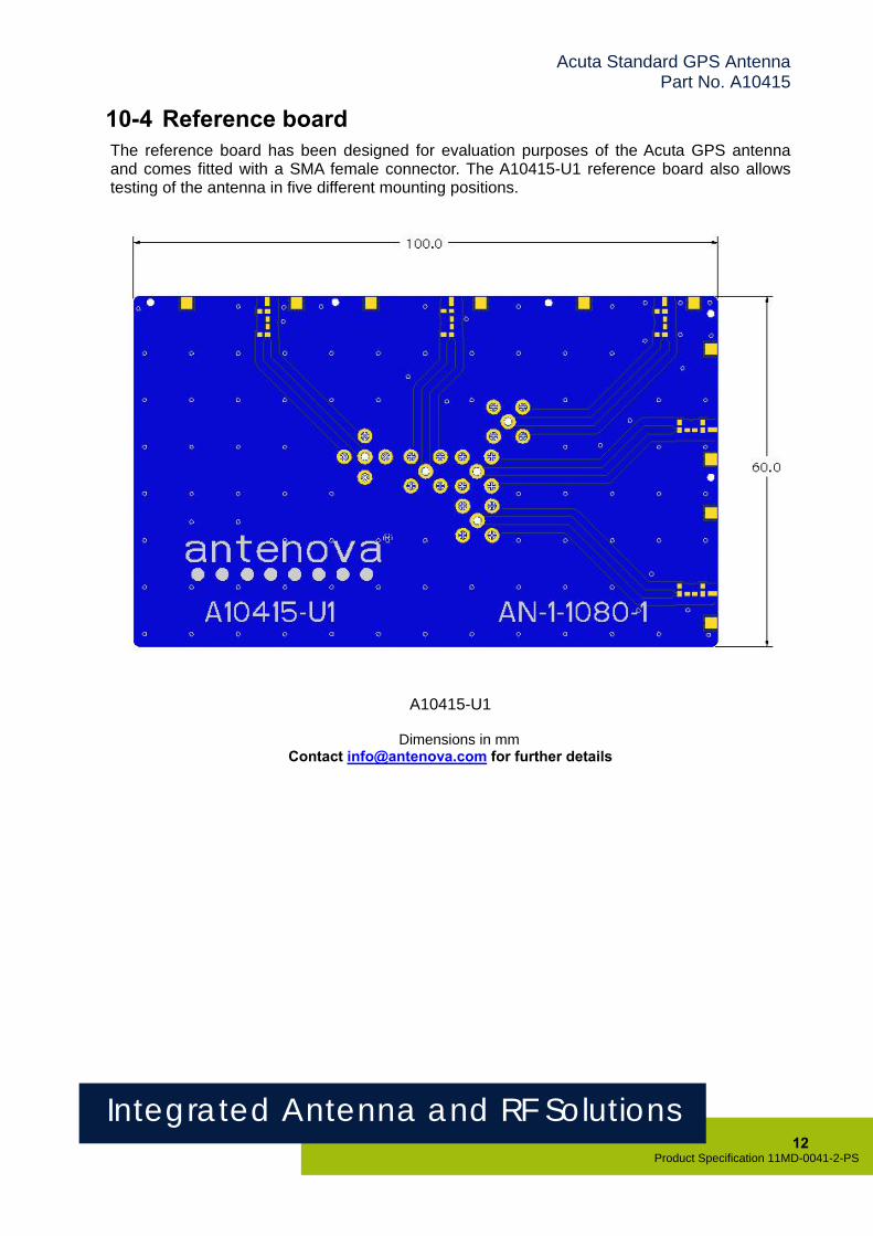
10-4 Reference board The reference board has been designed for evaluation purposes of the Acuta GPS antenna and comes fitted with a SMA female connector. The A10415-U1 reference board also allows testing of the antenna in five different mounting positions.
A10415-U1
Dimensions in mm Contact [email protected] for further details
Integrated Antenna and RF Solutions 12
Product Specification 11MD-0041-2-PS

Acuta Standard GPS Antenna Part No. A10415
Integrated Antenna and RF Solutions 13
Product Specification 11MD-0041-2-PS
11 Soldering The antenna is designed for hand-soldering; reflow soldering must not be used at it could damage the antenna.
This antenna is suitable for lead free soldering.
12 Hazardous material regulation conformance The antenna has been tested to conform to RoHS requirements. A certificate of conformance is available from Antenova’s website. 13 Packaging
13-1 Optimal storage conditions for packaged trays
Temperature -10ºC to 40ºC
Humidity Less than 75% RH
Shelf Life 18 Months
Storage place Away from corrosive gas and direct sunlight
Packaging Trays should be stored in unopened sealed manufacturer’s boxes.

Acuta Standard GPS Antenna Part No. A10415
13-2 Tray characteristics
Acuta
LT WT DT Wall T Quantity
330 ± 2.0 229 ± 2.0 12 ± 1.0 0.7 ± 0.1 100 pcs/tray Dimensions in mm
Integrated Antenna and RF Solutions 14
Product Specification 11MD-0041-2-PS

Acuta Standard GPS Antenna Part No. A10415
13-3 Box dimensions
LB WB DB Quantity
370 240 100 1000 pcs/box Dimensions in mm
Integrated Antenna and RF Solutions 15
Product Specification 11MD-0041-2-PS

Acuta Standard GPS Antenna Part No. A10415
www.antenova.com
Corporate Headquarters Antenova Ltd. Far Field House Albert Road Stow-cum-Quy Cambridge CB25 9AR Tel: +44 1223 810600 Fax: +44 1223 810650 Email: [email protected]
North America Headquarters Antenova Ltd. Rogers Business Park 2541 Technology Drive Suite 403 Elgin, IL 60124 Tel: +1 (847) 551 9710 Fax +1 (847) 551 9719 Email: [email protected]
Asia Headquarters Antenova Asia Ltd. 4F, No. 324, Sec. 1, Nei-Hu Road Nei-Hu District Taipei 11493 Taiwan, ROC Tel: +886 (0) 2 8797 8630 Fax: +886 (0) 2 8797 6890 Email: [email protected]
Copyright® 2011 Antenova Ltd. All Rights Reserved. Antenova® is a trademark of Antenova Ltd. Any other names and/or trademarks belong to their respective companies.
The materials provided herein are believed to be reliable and correct at the time of print. Antenova does not warrant the accuracy or completeness of the information, text, graphics or other items contained within these
information. Antenova further assumes no responsibility for the use of this information, and all such information shall be entirely at the user’s risk.
Integrated Antenna and RF Solutions 16
Product Specification 11MD-0041-2-PS Release Date 08 July 2011