adaptive terminal sliding mode control of a redundantly
TRANSCRIPT

HAL Id: lirmm-01084648https://hal-lirmm.ccsd.cnrs.fr/lirmm-01084648
Submitted on 19 Nov 2014
HAL is a multi-disciplinary open accessarchive for the deposit and dissemination of sci-entific research documents, whether they are pub-lished or not. The documents may come fromteaching and research institutions in France orabroad, or from public or private research centers.
L’archive ouverte pluridisciplinaire HAL, estdestinée au dépôt et à la diffusion de documentsscientifiques de niveau recherche, publiés ou non,émanant des établissements d’enseignement et derecherche français ou étrangers, des laboratoirespublics ou privés.
Adaptive Terminal Sliding Mode Control of aRedundantly-Actuated Cable-Driven Parallel
Manipulator: CoGiRoGamal El-Ghazaly, Marc Gouttefarde, Vincent Creuze
To cite this version:Gamal El-Ghazaly, Marc Gouttefarde, Vincent Creuze. Adaptive Terminal Sliding Mode Controlof a Redundantly-Actuated Cable-Driven Parallel Manipulator: CoGiRo. CableCon: Cable-DrivenParallel Robots, Tobias Bruckmann; Andreas Pott, Aug 2014, Duisburg, Germany. pp.179-200,�10.1007/978-3-319-09489-2_13�. �lirmm-01084648�

Adaptive terminal sliding mode control of aredundantly-actuated cable-driven parallelmanipulator: CoGiRo
Gamal El-Ghazaly, Marc Gouttefarde, and Vincent Creuze
Abstract This paper presents an extended adaptive control scheme viaterminalsliding mode (TSM) for cable-driven parallel manipulators(CDPM). Comparedwith linear hyperplane-based sliding mode control, TSM is able to guarantee high-precision and robust tracking performances which arise from its main feature offinite-time convergence. This motivates applying TSM to robotic manipulators ingeneral and, as presented in this paper, to CDPM in particular. The scheme pre-sented in this paper extends early developed TSM control schemes which are basedon partial knowledge of system dynamics. Instead, making use of the property thatthe dynamic models of mechanical manipulators are linear ininertial parameters,an adaptive control law is synthesised based on an appropriate choice of Lyapunovfunction which guarantees finite-time convergence to neighborhoodof sliding mode.A key challenge of the control of CDPM is that cable tensions must be admissible,i.e. lying in a non-negative range of admissible values. As long as cable tensionsare admissible, the overall dynamics of CDPM can be easily written in either ac-tuator space or operational space which in turn facilitatescontrol system design.The extended adaptive control scheme has been applied to a large redundantly ac-tuated CDPR prototype, CoGiRo. Simulation results show theeffectiveness of theproposed control method.
1 Introduction
Cable-driven parallel manipulator (CDPM) is a particular type of robots in whichthe motion of the platform (end-effector) is provided by varying the length of the ca-bles. Compared with classical parallel manipulators whichare characterised by their
Gamal El-Ghazaly, Marc Gouttefarde, and Vincent CreuzeLaboratoire d’Informatique, de Robotique et de Microelectronique de Montpellier (LIRMM,CNRS-UM2), 161 Rue Ada, 34392, Montpellier, France e-mail:{gamal.elghazaly,marc.gouttefarde, vincent.creuze}@lirmm.fr
1
2 Gamal El-Ghazaly, Marc Gouttefarde, and Vincent Creuze
limited workspace, CDPMs can have a very large workspace andalso capable ofmanipulating heavy loads at high operating speed [1] which make them useful char-acteristics for many potential industrial applications. For crane-like applications [2]such as pick and place tasks [3], suspended CDPM are usually used as they reducethe risk of cable collisions in the workspace area. Cable-suspended CDPM are notfully-constrained and cannot have wrench closure over the entire workspace. How-ever, a suspended CDPM uses the mobile platform and payload weights to keep thecables in tension. Furthermore, using more cables than DOFsin cable-suspendedCDPM can allow the robot to have a significantly wider workspace [3, 4, 5]. In thispaper, a 6-DOF suspended CDPM prototype with two degrees of actuation redun-dancy is used to evaluate the performance of the proposed TSMcontrol scheme.
Many challenges arise in CDPMs among which control design isa difficult one.These challenges stem from the fact that cables can only apply tension forces im-posing a strict constraint on control inputs. For redundantly actuated CDPM, aninfinite number of cable tension distributions exist for a given external forces ap-plied to the platform. The redundancy resolution has attracted the attention of manyresearchers. The proposed algorithms to resolve redundancy can be categorised intotwo main classes namely, iterative algorithms and non-iterative algorithms. Iterativealgorithms are usually based on optimization and are not always suitable for realtime implementations [6, 7, 8]. On the other hand, non-iterative algorithms give asolution in a reasonable amount of time and can be more easilyimplemented inreal-time [9, 10, 5].
Compared to the great deal of attention that has been paid to motion controlof rigid-link manipulators, only relatively few results ofcontrol of CDPM exist inthe literature. Gholamiet-al. [11] proposed an operational-space PD controller fortrajectory tracking. Kawamuraet-al. proposed a PD controller with gravity com-pensation in [1]. The PD controller is designed in the actuator-space with Lyapunovstability. A robust Lyapunov-based design of PID tracking controller has been in-troduced for a fully-constrained planar CDPM in [12]. A PD controller with adap-tive compensation has been applied to fully-constrained CDPM in [13]. Computed-torque control methods appeared in [14]. To make use of the advantages of both theactuator-space and operational-space formulations, a dual space adaptive controllerhas been proposed in [15].
Sliding mode control (SMC) has been found effective to deal with dynamicsystems with uncertainties, time-varying parameters, andbounded external distur-bances [16]. The main idea of SMC is to force the states of the system to stay ina chosen switching manifold satisfying a desired dynamic behavior. The choice oflinear hyperplanes as switching manifolds guarantee asymptotic stability i.e. theclosed-loop error converges to the neighborhood of the origin as the time approachsto infinity. Although classical SMC gave reasonable performance for robotic manip-ulators, only few results for CDPMs exist in the literature [17]. The performance ofclassical SMC could be enhanced if the closed-loop errors are forced to reach theorigin in finite time. SMC with finite-time stabilization arecalled terminal slidingmode (TSM). Several ideas of designing TSM based control schemes have been de-veloped to achieve finite-time stabilization in [18, 19, 20,21]. The control schemes

Adaptive terminal sliding mode control of a redundantly-actuated of CDPM 3
based on those ideas are able to guarantee high-precision and robust tracking per-formances due to finite-time convergence even with high uncertainty. This prop-erty justifies adopting TSM based control schemes for robotic manipulators andmotivates us to use it for CDPMs. TSM control schemes developed for rigid-linkmanipulators may not exploit their properties very well. Even adaptive TSM controlschemes developed for rigid-link manipulators do not rely on the linearity of inertialparameters [22]. In [18], a robust TSM control has been developed for robotics ma-nipulators. However, the main problem of this scheme is thatcontroller singularitymay be reached in sliding mode. A non-singular TSM has been proposed for roboticmanipulators in [19] where a new terminal sliding manifold has been proposed toavoid controller singularity. However, this control scheme did not eliminate chatter-ing in control inputs. A continuous and non-singular TSM control scheme has beenproposed also for robotic manipulators in [20] to avoid bothchattering and singular-ity. However, the proposed schemes in [18, 19, 20] did not consider the aforemen-tioned property of the dynamic model of robotics manipulator and therefore cannotbe directly applied to control CDPM for which high uncertainty may appear spe-cially when manipulating payloads of varying sizes and weights. Instead, adaptiveTSM control scheme has been proposed also for robotic manipulators in [23] wherethe Coriolis, centrifugal and gravity terms are approximated by polynomials of firstorder. The role of the adaptive mechanism is to estimate the coefficients of thesepolynomials which approximate the manipulator dynamics. However, [23] did notestimate the true inertial parameters of the manipulator which may give relativelylarge control inputs specially when loads are introduced.
This paper extends an early developed non-singular continuous TSM controlscheme for robotic manipulators proposed in [20] by incorporating an adaptivemechanism to estimate dynamic parameters and by applying itto CDPM. Thescheme in [20] is based on the assumption that the nominal values of inertial ma-trix components as well as of Coriolis, centrifugal and gravity forces are knownand their corresponding uncertainties have known bounds. It is worth noting thatthe CDPMs considered in this paper are designed to carry heavy payloads havingdifferent weights so that the mobile platform inertial parameters are subjected tolarge variations. Therefore, if the scheme in [20] is directly applied, very high con-trol input torques may be required especially during loading situations. The mostappropriate solution to this problem is to estimate online the dynamic parametersof the CDPM via an adaptive mechanism. In this paper, the overall dynamics ofCDPMs (both winches and platform) is formulated to be linearin all inertial andfriction parameters. Thereby, it facilitates the design ofthe adaptive control scheme.The whole control scheme is synthesised and analysed based on Lyapunov stabil-ity theory. Moreover, it guarantees the finite-time convergence of the closed-loopsystem. To show its effectiveness, the proposed control scheme is applied to a largeredundantly actuated CDPM, CoGiRo [3].
The paper is organised as follows. In Section 2, kinematic and dynamic model-ing of CDPMs are presented and some properties of the dynamicmodel are recalled.Section 3 focuses on the proposed adaptive terminal slidingmode control schemewhere finite-time convergence stability of the overall closed-loop system is analysed

4 Gamal El-Ghazaly, Marc Gouttefarde, and Vincent Creuze
via Lyapunov direct method. Finally, to show the effectiveness of the proposed con-trol scheme, a simulation study for pick-and-place task is performed on the CoGiRoCDPM in Section 4. Section 5 concludes this paper.
2 Kinematic and Dynamic Modeling of CDPM
Fig. 1: Schematic Diagram of a General CDPM
In this section, kinematic and dynamic modeling of CDPM are presented. We as-sume that the elasticity of cables is negligible and cables almost behave as masslessrigid strings. Modeling of CDPM has been presented in many research work beforee.g. [24, 25, 26, 3]. However, in this section, our main objective is to present theoverall dynamics of CDPM (bothwinchesandplatform) in compact form and linearin all dynamic parameters. This compact form facilitates the design of adaptive con-trol schemes in general [22, 27] and is particularly suitable for the adaptive controlscheme introduced in this paper. The notations of a general CDPM for kinematicmodeling is shown in Fig. 1.

Adaptive terminal sliding mode control of a redundantly-actuated of CDPM 5
2.1 Kinematic Model
As shown in Fig. 1, CDPM is composed of a moving platform linked to a fixed basethrough cables with varying lengths via winches which are generally attached to thebase structure. LetRb andRp denote two frames assigned to the base and movingplatform, respectively. In the case of CDPM withm cables, let cablei connects thepointAi at which it extends from the base frame to pointBi at which it is attached tothe moving platform. The position and orientationRp with respect toRb is definedby the configuration vectorx = [ pT ϕT ]T wherep= [x y z]T is the position vectorandϕ = [φ θ ψ ]T is a vector representing the orientation ofRp with respect toRb
using Euler angles. The rotation matrix fromRb to Rp denoted byRpb is represented
by three successive rotations as
Rpb(φ ,θ ,ψ) = Rot(x,φ)Rot(y,θ )Rot(z,ψ). (1)
Using the definition of elementary rotations around coordinate axes,Rpb can be
written as
Rpb(φ ,θ ,ψ) =
CθCψ −CθSψ SθCφSψ +SφSθCψ CφCψ −SφSθSψ −SφCθSφSψ −CφSθCψ SφCψ +CφSθSψ CφCθ
, (2)
whereC(·) = cos(·) andS(·) = sin(·). If qi denotes motori angular position andr i
represents motori angular position to cable length transmission ratio, then the cablelengthl i can be expressed as
l i = r iqi. (3)
Let q =[
q1 q2 . . . qm]T
∈ Rm, and L =
[
l1 l2 . . . lm]T
∈ Rm be two vectors
gathering angular position variables and cable lengths, respectively. Then, one canwrite (3) in a vector matrix form as
L = Rq, (4)
whereR is a diagonal matrix containing the transmission ratiosr i i.e.
R = diag{r1, r2, . . . , rm}. (5)
Let ai denotes the position vector corresponding to pointAi expressed inRb, bi
denotes the position vector corresponding to pointBi expressed inRp, andui is avector along the direction of cablei and has the same magnitude of the cable length.Given the position and orientation of the moving platformx, the loop closure ofcablei expressed inRb can be written as follows
ui = p−ai +Rpbbi. (6)
The length of cablei is then computed as
l2i = uTi ui = [p+Rp
b bi −ai]T [p+Rp
b bi −ai]. (7)

6 Gamal El-Ghazaly, Marc Gouttefarde, and Vincent Creuze
Differentiating (7) with respect to time together with (4) gives
L = Rq = J(x)x, (8)
whereJ(x) defines a 6×mJacobian matrix of the CDPM. The second-order deriva-tive (7) with respect is then written as
L = Rq = J(x)x+ J(x, x)x. (9)
2.2 Platform Dynamics
Let S=[
Sx Sy Sz]T
be a position vector of the platform COMG in Rp. Let I p =
Io−MSS be the inertia tensor of the platform with respect to the origin of Rp andexpressed in the same frame, whereIo is the inertia tensor with respect to COM ofthe platform, M is the total platform mass, andS denotes the 3×3 skew-symmetricmatrix associated toS. Let us denote the matrixI p as
I p =
XX XY XZXY YY YZXZ YZ ZZ
. (10)
Let MS be a vector representing the first moment of the moving platform whichcan be expressed as
MS = M[
Sx Sy Sz]T
=[
MX MY MX]T
. (11)
The dynamics of the platform can be written in the following form
A(x)x+C(x, x)x+Q(x) =−JTt, (12)
whereA(x) denotes the generalized inertia matrix,C(x, x) is the Coriolis and cen-trifugal matrix,Q(x) is a vector of gravity forces, andt is a vector of cable tensions.It is worth noting that the dynamics of the platform is linearin the inertial param-eters i.e. inI p, MS, and M [22]. Letχp ∈ R
10 be a vector collecting the inertialparameters of the platform as
χp =[
XX XY XZ YY YZ ZZ MX MY MZ M]T
. (13)
Consequently, one can easily express the dynamics of the platform in the follow-ing regression form
Φp(x, x, x)χp =−JT t. (14)
The details of the regressorΦp(x, x, x) is given in [15].

Adaptive terminal sliding mode control of a redundantly-actuated of CDPM 7
2.3 Winches Dynamics
The dynamics of the winches can be written as follows [15]
ΓΓΓa = Iaq+Fvq+Fcsign(q)+Rt (15)
whereIa ∈ Rm×m, Fv ∈ R
m×m, andFc ∈ Rm×m are diagonal matrices denoting, re-
spectively, the inertia, the viscous friction coefficients, and the dry friction coeffi-cients of the motors, drums and other other rotating parts. Let Ia,Fv, and Fc ∈ R
m
be vectors corresponding to the diagonal elements ofIa, Fv, andFc, respectively.Then, one can gather all dynamic parameters of the winches inone vectorχa ∈R
3m
defined as followsχa =
[
ITa FT
v FTc
]T(16)
Now, the winch dynamics can be written in a regression form asfollows
ΓΓΓa = Φa(q, q, q)χa+Rt (17)
whereΦa(q, q, q) is given by
Φa(q, q, q) =[
diag(q) | diag(q) | diag(sign(q))]
(18)
As cable tensions must be within admissible non-negative ranges i.e. 0≤ tmin ≤t ≤ tmax, the limits of the actuator torques should be within a lower and upper limitsdefined respectively as follows
ΓΓΓmina = Φa(q, q, q)χa+Rtmin (19)
and
ΓΓΓmaxa = Φa(q, q, q)χa+Rtmax (20)
In this paper, the dynamics of winches will be projected ontothe operationalspace and then cable tensions will not be directly accessible. Instead, the tension dis-tribution algorithm will be applied on the bounds defined by Eq. (19) and Eq. (20).
2.4 CDPM Dynamics in Operational Space
Using the first-order and second-order differential modelsdefined by Eq. (8) andEq. (9), one can compute the winch regression matrix in termsof either the plat-form or the winch acceleration, velocity, and position vectors e.g.Φa(q, q, q) ⇔Φa(x, x, x). Using Eq. (17), the cable tension can be expressed as
t = R−1(ΓΓΓa−Φa(x, x, x)χa) (21)
8 Gamal El-Ghazaly, Marc Gouttefarde, and Vincent Creuze
Substituting cable tensions in Eq. (21) into platform dynamics given by Eq. (14)yields
Φp(x, x, x)χp− JTR−1Φa(x, x, x)χa =−JTR−1ΓΓΓa (22)
Eq. (22) can be written in a more compact form as
Φ(x, x, x)χ =−JTR−1ΓΓΓa (23)
where
Φ(x, x, x) =[
Φp(x, x, x) − JT R−1Φa(x, x, x)]
and χ =[
χTp χT
a
]T(24)
Solving Eq. (23) for the actuator torquesΓΓΓa taking into account the torque limitsdefined by Eq. (19) and Eq. (20), gives the following general solution
ΓΓΓa = RW+Φ(x, x, x)χ +RNλ , (25)
whereW+ ∈Rm×6 andN∈R
m×m−6 are the Moore-Penrose pseudo-inverse and thenull-space basis matrix of−JT , respectively.λ ∈ R
m−6 is an arbitrary vector to beobtained such that cable tensions (and actuator torques) are admissible. For the sakeof controller synthesis and analysis, the dynamic model of the CDPM expressed interms of an inertia matrix, Coriolis, centrifugal, gravityforces, and friction forcesare needed. Straightforward manipulations after substituting Eq. (15) into Eq. (12),and considering an external disturbancesFd, allow us to write the dynamics of theCDPM in the following form
Aeq(x)x+Ceq(x, x)x+Qeq(x)+Feq(x, x, x) = Fext+Fd (26)
whereAeq(x)=A(x)−JTR−1IaR−1J, Ceq(x, x)=C(x, x)−JTR−1IaR−1J, Qeq(x)=Q(x), Feq(x, x, x)=−JTR−1FvR−1Jx−JTR−1Fcsign(R−1Jx), andFext=−JTR−1ΓΓΓa.
2.5 Properties of the Dynamic Model
Some properties of the dynamic model (26) are recalled [12].These properties arenecessary for the controller synthesis and stability analysis.
Property1 The inertia matrixAeq(x) is a positive-definite symmetric matrix andbounded away from singularity whatever the uncertainties in inertialparameters. The boundedness ofAeq(x) implies
λmI6 ≤ Aeq(x)≤ λMI6 (27)
orλm ≤ ‖Aeq(x)‖ ≤ λM (28)
whereI6 is the 6×6 identity matrix andλm andλM are positive scalars.

Adaptive terminal sliding mode control of a redundantly-actuated of CDPM 9
Property2 The external disturbance force vectorFd is assumed to be bounded i.e.
‖Fd‖ ≤ ζ (29)
whereζ is a positive constant.
3 Adaptive TSM Control of CDPM
In this section, an adaptive TSM control is synthesized for the CDPM dynamicmodel given in (26). The main idea of TSM is first presented assuming that thedynamic parameters of the CDPM are known. Then, the idea is extended to theadaptive case where the dynamic parameters are assumed to beunknown and mustbe estimated.
3.1 TSM Control
For CDPM dynamics given by (26), letxd, xd, andxd be a desired trajectory anddefinee= x−xd as the tracking error. The control objective is to design a feedbackcontrol lawFext such that the platform posturex tracks the desired trajectoryxd infinite time.
In order to have a terminal convergence of tracking errors, asliding surface isdefined as follows [18]
s= e+βe p/q (30)
whereβ > 0 is a design constant parameter,p andq are positive odd integers satis-fying p> q. In order to ensure that the terminal sliding mode exists on the switchingsurface and equilibrium is reached in finite time, the following η-reachability con-dition must be satisfied [28]
12
ddt
sTs<−η∣
∣s∣
∣ (31)
whereη > 0 is a constant. If the dynamic parametersχ of the CDPM are knownand the bounds on disturbanceζ are also known, then, one can choose the followingcontrol law to satisfy theη-reachability condition [19].
Fext = Φ(x, x,v)χ (32)
wherev is an auxiliary control input defined by
v = xd +βqp
e p/q−1e+(ρ +η)sign(s) (33)

10 Gamal El-Ghazaly, Marc Gouttefarde, and Vincent Creuze
whereρ = λmζ . If s(0) 6= 0, then the sliding modes= 0 will be reached in finitetime tr which satisfiestr ≤
∣
∣s∣
∣/η . When the sliding mode is reached, the systemdynamics is described by the following nonlinear differential equation
e+βe p/q = 0 (34)
Eq. (34) has an equilibrium at e= 0 which is a globally finite-time stable attractor.And the convergence time for any initial condition x= x(tr) is finite and given by
ts ≤p
β (p−q)
∣
∣x(tr)∣
∣
1−q/p(35)
However, the choice of such terminal sliding surface may cause singularity atconvergence due to fractional powerp/q. In addition, the control laws (32) and (33)is discontinuous and may cause chattering [19].
3.2 Non-Singular TSM Control
In order to avoid the singularity problem of (30), another choice of terminal slidingmode is defined as follows [20]
s= e+β∣
∣e∣
∣
γsign(e) (36)
whereβ > 0 and 1< γ < 2.
Remark 1.The terminal sliding mode defined by (36) has a global finite-time equi-librium i.e. for any given initial conditione(0) 6= 0, the variablee reaches zero in afinite timetr given by [20]
tr ≤γβ 1/γ
(γ −1)
∣
∣e(0)∣
∣
(γ−1)/γ(37)
Remark 2.The terminal sliding mode defined by (36) is continuous and time differ-entiable. Its first time derivative is written as [20]
s= e+β γ∣
∣e∣
∣
γ−1 e (38)
Remark 3.Finite time stability is guaranteed for a given Lyapunov function candi-date V(s) if it satisfies [20]
V(s)+aV(s)+bVc(s)≤ 0; a> 0,b> 0, and 0< c< 1 (39)
Moreover, the finite reaching time is given by
tr ≤1
a(1− c)ln
aVc(s(0))+bb
(40)

Adaptive terminal sliding mode control of a redundantly-actuated of CDPM 11
Now, if we assume that the dynamic parameters of CDPM i.e.χ are known andthe disturbanceFd = 0, then to design a non-singular TSM controller, let us choosethe following Lyapunov function candidate
V =12
sTs (41)
The time derivative of the non-singular TSM (38) can be rewritten as follows
s= β γ∣
∣e∣
∣
γ−1(β−1γ−1
∣
∣e∣
∣
2−γsign(e)+ e) (42)
Let us choose a control law which is defined by
Fext = Φ(x, x,v)χ −K1s−K2∣
∣s∣
∣
ρsign(s) (43)
whereK1 = diag(k11, k12, . . . k16), K2 = diag(k21, k22, . . . k26), with ki j > 0, i ∈{1,2}, j ∈ {1,2, . . . ,6}, andρ < 1, and
v = xd −1
β γ∣
∣e∣
∣
2−γsign(e) (44)
The control laws (43) and (44) reduces the time-derivative of V to
V =−sTH1s− sTH2∣
∣s∣
∣
ρ sign(s) (45)
where
H1 = diag(h11, h12, . . . h16) = β γλm∣
∣e∣
∣
γ−1K1 (46)
and
H2 = diag(h21, h22, . . . h26) = β γλm∣
∣e∣
∣
γ−1K2 (47)
are positive diagonal matrices anywhere except at sliding mode. After straightfor-ward manipulations of (45), one can get
V ≤−2h1V −2(ρ+1)/2−h2V(ρ+1)/2 (48)
According to the finite-time stability (39), it is clear that(48) ensures that thetracking errore converges to zero along TSM in finite time. However, in practice,the vector of dynamic parametersχ is not exactly known since it changes with pay-loads. Also, external disturbances exist and must be taken into account in controllerdesign. Therefore, an adaptive control scheme is recommended to cope with loadchanges and at the same time to guarantee robustness of performances. The maincontribution of this paper is to extend the non-singular TSMcontrol scheme ex-plained above such that the dynamic parameters of CDPM are updated online via anadaptation mechanism to ensure convergence.

12 Gamal El-Ghazaly, Marc Gouttefarde, and Vincent Creuze
3.3 Adaptive TSM Control Scheme
In this section, a non-singular adaptive TSM is developed for CDPM based on theclassical formulations presented in Sections 3.1 and 3.2. The dynamic parametersare assumed to be unknown and have to be estimated. The main results of the pro-posed non-singular adaptive TSM control scheme are summarised through the fol-lowing theorem.
Theorem 1.Consider a CDPM described by (23) and (26) and satisfying (27), (28),and (29) and assume that the vector of dynamic parametersχ is unknown. If thenon-singular TSM (36) is chosen and the following control scheme is applied:
Fext = Φ(x, x,v)χ +us (49)
whereχ is an estimate ofχ , and
v = xd −1
β γ∣
∣e∣
∣
2−γsign(e), (50)
us =−K1s−K2∣
∣s∣
∣
ρsign(s), (51)
and
˙χ = β γΛΦT(x, x,v)∣
∣e∣
∣
1−γ s (52)
whereΛ is a positive-definite diagonal matrix with appropriate dimensions, then theclosed-loop system reaches a neighborhood of TSM in finite time and the trackingerror reaches the neighborhood of the origin also in finite time.
Proof. Let χ = χ − χ be dynamic parameters estimation error. Let us choose aLyapunov function candidate as follows
V =12
sTs+12
χTΛΛΛ−1χ (53)
The time derivative of V is given by
V = sTs− χTΛΛΛ−1 ˙χ (54)
The time derivative of the terminal slidings can be rewritten in the followingform
s= β γ∣
∣e∣
∣
γ−1A−1eq (Aeq(β−1γ−1
∣
∣e∣
∣
2−γ sign(e))+Aeqe) (55)
whereAeq, Ceq, Qeq, andFeq are the inertia matrix, Coriolis and centrifugal matrix,gravity forces, and friction forces where the arguments aresuppressed for simplicity.The second-order time derivative of tracking errore can be written as
Aeqe=−Aeqxd −Ceqx−Qeq−Feq+Fext+Fd (56)
Substituting (56) into (55) gives
Adaptive terminal sliding mode control of a redundantly-actuated of CDPM 13
s= β γ∣
∣e∣
∣
γ−1A−1eq (Aeq(β−1γ−1
∣
∣e∣
∣
2−γsign(e)− xd)−Ceqx−Qeq−Feq+Fext+Fd)
(57)By definition ofv in (50), Eq. (57) can rewritten as
s= β γ∣
∣e∣
∣
γ−1 A−1eq (−Φ(x, x,v)χ +Fext+Fd) (58)
Substituting the control law (51) and (49), then (58) can be simplified to
s= β γ∣
∣e∣
∣
γ−1A−1eq (Φ(x, x,v)χ −K1s−K2
∣
∣s∣
∣
ρsign(s)+Fd) (59)
Substituting (59) intoV in (60) and substituting with the adaptive law (52), onecan easily get
V ≤ β γsT∣
∣e∣
∣
γ−1A−1eq (−K1s−K2
∣
∣s∣
∣
ρsign(s)+Fd) (60)
Using the properties (28) and (29), then one can simplify (60) as
V ≤ β γsT∣
∣e∣
∣
γ−1 λm(−K1s−K2∣
∣s∣
∣
ρsign(s)+ ζ ) (61)
Following the same line of proof as in [20], we can see that thesystem can reachneighborhood sliding-mode in finite-time which is defined by
‖s‖ ≤ δ = min(δ1,δ2) (62)
whereδ1 = λmζ/h1, δ2 = (λmζ/h2)(1/ρ). In addition, once the sliding variable is
within the regionδ , the tracking error can reach the neighborhood of the originalsoin finite time as well. This completes the proof.
4 Simulation Study: Control of CoGiRo
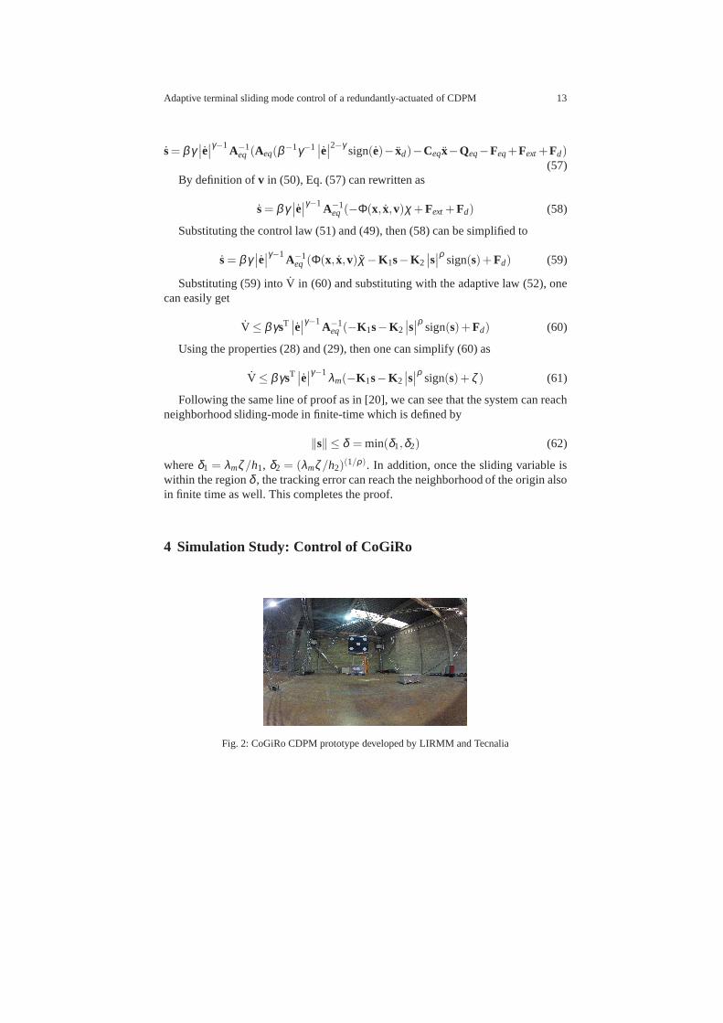
Fig. 2: CoGiRo CDPM prototype developed by LIRMM and Tecnalia

14 Gamal El-Ghazaly, Marc Gouttefarde, and Vincent Creuze
Table 1: Cable Attach Points
Base Points Platform Points
xb yb zb xp yp zp
a1 -7.5 -5.5 6 b1 0.5 -0.5 0a2 -7.5 -5.5 6 b2 -0.5 0.5 1a3 -7.5 5.5 6 b3 -0.5 -0.5 0a4 -7.5 5.5 6 b4 0.5 0.5 1a5 7.5 5.5 6 b5 -0.5 0.5 0a6 7.5 5.5 6 b6 0.5 -0.5 1a7 7.5 -5.5 6 b7 0.5 0.5 0a8 7.5 -5.5 6 b8 -0.5 -0.5 1
units are inm
Table 2: Platform inertial parameters
Parameter XX YY ZZ XY XZ YZ MX MY MZ M
χPNL 62.00 60.00 22.00 -0.32 -0.02 4.50 0.00 -7.50 0.00 79.00χPL 132.00 135.00 45.00 0.00 -3.00 -2.00 -28.00 -7.50 0.00 200.00
a χPNL andχPL denote platform inertial parameters without and with load,respectively. Units arein kg.m2, kg.m, andkg
Table 3: Winch dynamic parameters
Parameter Ia Fv Fc r
Value 0.0311 0.0200 3.0000 0.0225
units are inkg.m2, N.m.rad−1.sec, N.m, m
4.1 CoGiRo Prototype
The CoGiRo prototype shown in Fig. 2 is a redundantly-actuated cable-suspendedCDPM developed by LIRMM and Tecnalia. CoGiRo occupies a space characterisedby a 15m in length, 11m in width, and 15m in length giving a potential workspaceof 677m3. The mobile platform is a cube with 1mside length with a total mass of 79kg. CoGiRo has 8-actuators with a 6-DOF moving platform i.e. ithas 2-degrees ofactuation redundancy. CoGiRo is capable of manipulating payloads of 300kg overthe entire workspace and up to 500kg if the task to be performed is not too closeto the boundaries of the workspace. The lower limit of cable tension istmin = 0 Nand the upper limit istmax= 5000N. The base and platform cable attachment pointsof CoGiRo which are given Table 1 in units ofm. The inertial parametersχPNL of

Adaptive terminal sliding mode control of a redundantly-actuated of CDPM 15
the moving platform from the CAD model of CoGiRO are given in Table 2. Theinertial parametersχPL of the platform with a typical payload previously used in anexperimental study are used to assess the robustness of the proposed control schemein this simulation study. The dynamic parameters of CoGiRo winches are shown inTable 3.
4.2 Simulation Results
Table 4: Interpolated trajectory point sequence
Point x y z φ θ ψ
x0 0.000 0.000 1.296 0.000 0.000 0.000x1 0.000 0.000 2.296 0.000 0.000 0.000x2 -3.850 1.200 2.296 0.000 0.000 -45.840x3 -3.850 1.200 1.307 0.000 0.000 -45.840x4 -3.000 2.000 1.307 0.000 0.000 -45.840x5 -3.000 2.000 1.796 0.000 0.000 -45.840x6 4.000 -1.000 1.796 0.000 0.000 11.460x7 4.000 -1.000 1.307 0.000 0.000 11.460x8 4.300 -2.000 1.307 0.000 0.000 11.460x9 4.300 -2.000 2.296 0.000 0.000 11.460x10 0.000 0.000 2.296 0.000 0.000 0.000x11 0.000 0.000 1.296 0.000 0.000 0.000
Table 5: Maximum velocity and acceleration along the trajectory
DOF x y z φ θ ψ
Maximum velocityK v [{m, rad}/sec] 1.0000 1.0000 1.0000 1.5708 1.5708 1.5708Maximum accelerationKa [{m, rad}/sec2] 0.1000 0.1000 0.1000 0.1571 0.1571 0.1571
CoGiRo is supposed to perform pick-and-place tasks. In thissimulation study,a trajectory of 11 mobile platform poses corresponding to a pick-and-place task isgiven in Table 4. It has been generated by a 5th-order polynomial interpolation sub-jected to the velocity and acceleration constraints given in Table 5. In order to assessthe performance of the proposed adaptive TSM control scheme, we consider twosimulation cases. InCase A, the adaptive TSM controller is simulated consideringonly 20% of parametric uncertainty where inCase B, we consider loading the plat-form at configurationx3 and releasing the load at configurationx6 and, at the same

16 Gamal El-Ghazaly, Marc Gouttefarde, and Vincent Creuze
Table 6: Adaptive TSM Controller Parameters
Parameter Value
β 1.00γ 1.50ρ 0.33
K1 diag{70.00, 70.00, 105.00, 105.00, 105.00, 70.00}K2 diag{25.00, 25.00, 37.50, 25.00, 25.00, 30.00}ΛI p diag{1000.00, 1000.00, 1000.00, 1000.00, 1000.00, 1000.00}ΛMS diag{200.00, 200.00, 200.00}ΛIa diag{0.10, 0.10, 0.10, 0.10, 0.10, 0.10, 0.10, 0.10}ΛFv diag{0.01, 0.01, 0.01, 0.01, 0.01, 0.01, 0.01, 0.01}ΛFc diag{0.10, 0.10, 0.10, 0.10, 0.10, 0.10, 0.10, 0.10}
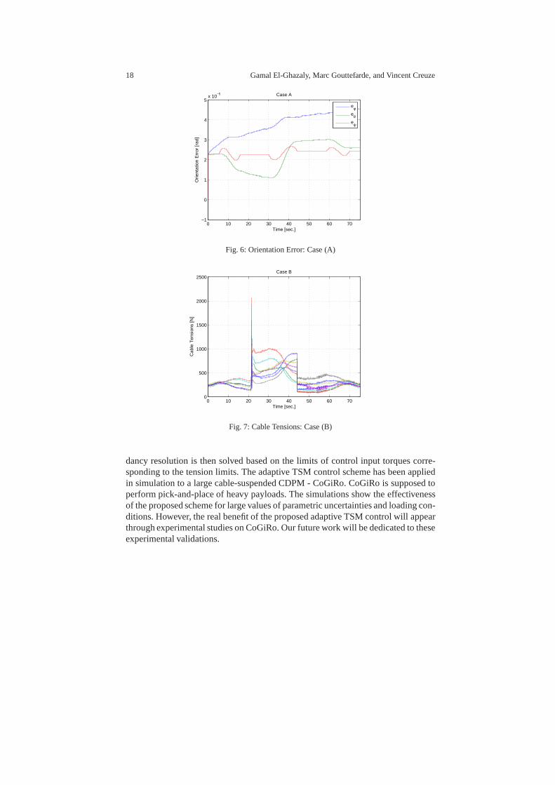
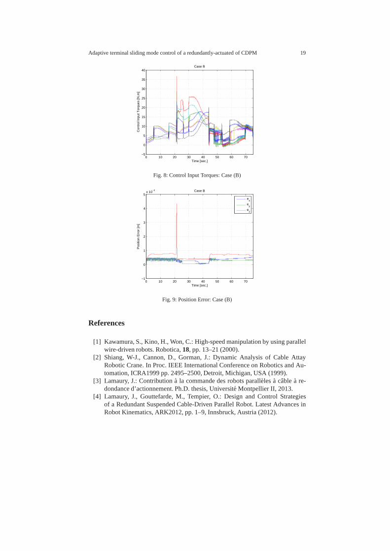
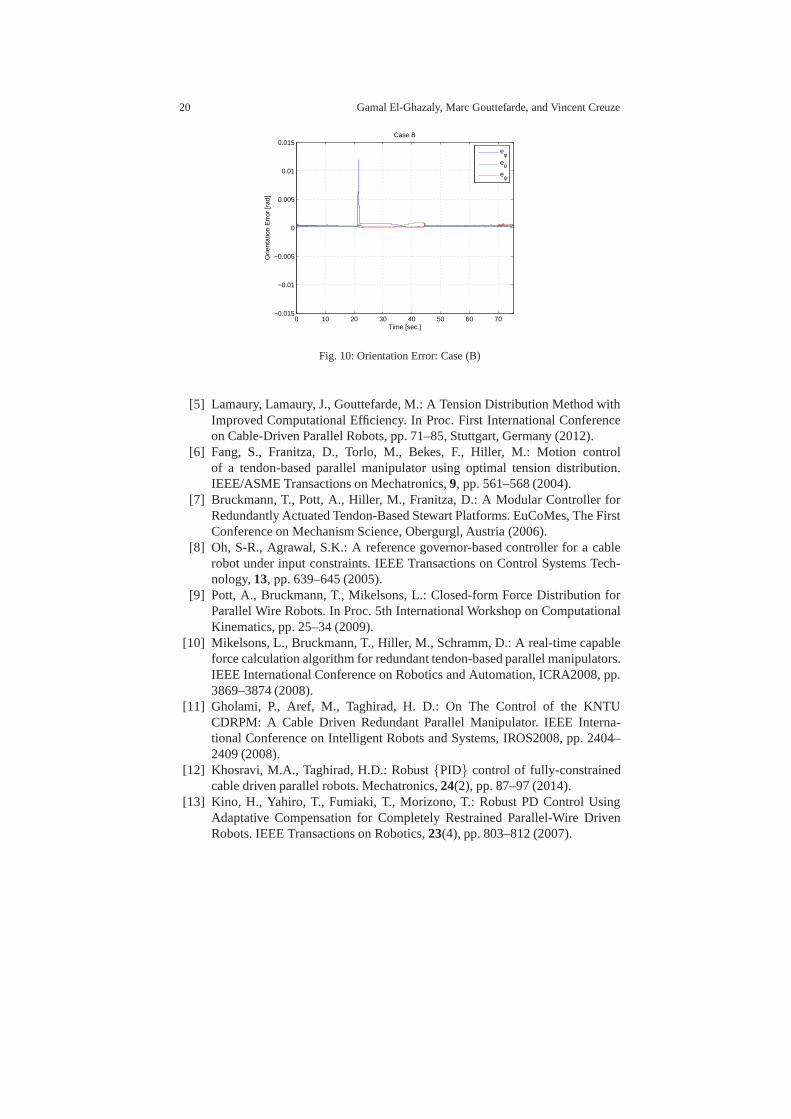
time, the adaptive TSM control algorithm is initialised with 20% of parametric un-certainty for the no-load platform inertial parametersχPNL. The parameters shownin Table 6 have been used in simulation of both cases whereΛi is the adaptationgains corresponding to the parameters ofi.
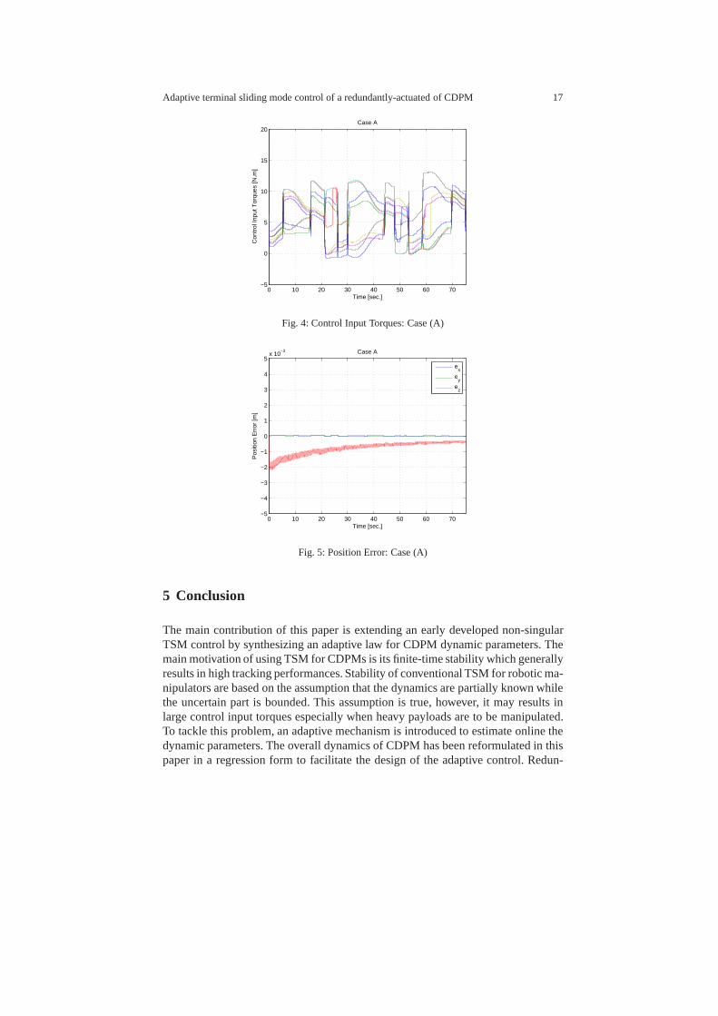
Fig. 3, 4, 5, and 6 show the simulation results ofCase A. It can be seen thatthe proposed adaptive TSM control scheme is able to achieve good tracking perfor-mance even with parametric uncertainty. Fig. 7, 8, 9, and 10 show the simulationresults ofCase B. It can be seen that at the loading instant, both cable-tension andcontrol input torques increase instantaneously. However the adaptive TSM is ableto restore the tracking error in short period of time and achieves a good trackingperformance over the whole trajectory.
0 10 20 30 40 50 60 700
100
200
300
400
500
600
700
Time [sec.]
Cab
le T
ensi
ons
[N]
Case A
Fig. 3: Cable Tensions: Case (A)
Adaptive terminal sliding mode control of a redundantly-actuated of CDPM 17
0 10 20 30 40 50 60 70−5
0
5
10
15
20
Time [sec.]
Con
trol
Inpu
t Tor
ques
[N.m
]
Case A
Fig. 4: Control Input Torques: Case (A)
0 10 20 30 40 50 60 70−5
−4
−3
−2
−1
0
1
2
3
4
5x 10
−3
Time [sec.]
Pos
ition
Err
or [m
]
Case A
e
x
ey
ez
Fig. 5: Position Error: Case (A)
5 Conclusion
The main contribution of this paper is extending an early developed non-singularTSM control by synthesizing an adaptive law for CDPM dynamicparameters. Themain motivation of using TSM for CDPMs is its finite-time stability which generallyresults in high tracking performances. Stability of conventional TSM for robotic ma-nipulators are based on the assumption that the dynamics arepartially known whilethe uncertain part is bounded. This assumption is true, however, it may results inlarge control input torques especially when heavy payloadsare to be manipulated.To tackle this problem, an adaptive mechanism is introducedto estimate online thedynamic parameters. The overall dynamics of CDPM has been reformulated in thispaper in a regression form to facilitate the design of the adaptive control. Redun-
18 Gamal El-Ghazaly, Marc Gouttefarde, and Vincent Creuze
0 10 20 30 40 50 60 70−1
0
1
2
3
4
5x 10
−5
Time [sec.]
Orie
ntat
ion
Err
or [r
ad]
Case A
eφeθeψ
Fig. 6: Orientation Error: Case (A)
0 10 20 30 40 50 60 700
500
1000
1500
2000
2500
Time [sec.]
Cab
le T
ensi
ons
[N]
Case B
Fig. 7: Cable Tensions: Case (B)
dancy resolution is then solved based on the limits of control input torques corre-sponding to the tension limits. The adaptive TSM control scheme has been appliedin simulation to a large cable-suspended CDPM - CoGiRo. CoGiRo is supposed toperform pick-and-place of heavy payloads. The simulationsshow the effectivenessof the proposed scheme for large values of parametric uncertainties and loading con-ditions. However, the real benefit of the proposed adaptive TSM control will appearthrough experimental studies on CoGiRo. Our future work will be dedicated to theseexperimental validations.
Adaptive terminal sliding mode control of a redundantly-actuated of CDPM 19
0 10 20 30 40 50 60 70−5
0
5
10
15
20
25
30
35
40
Time [sec.]
Con
trol
Inpu
t Tor
ques
[N.m
]
Case B
Fig. 8: Control Input Torques: Case (B)
0 10 20 30 40 50 60 70−1
0
1
2
3
4
5x 10
−3
Time [sec.]
Pos
ition
Err
or [m
]
Case B
e
x
ey
ez
Fig. 9: Position Error: Case (B)
References
[1] Kawamura, S., Kino, H., Won, C.: High-speed manipulation by using parallelwire-driven robots. Robotica,18, pp. 13–21 (2000).
[2] Shiang, W-J., Cannon, D., Gorman, J.: Dynamic Analysis of Cable AttayRobotic Crane. In Proc. IEEE International Conference on Robotics and Au-tomation, ICRA1999 pp. 2495–2500, Detroit, Michigan, USA (1999).
[3] Lamaury, J.: Contribution a la commande des robots paralleles a cable a re-dondance d’actionnement. Ph.D. thesis, Universite Montpellier II, 2013.
[4] Lamaury, J., Gouttefarde, M., Tempier, O.: Design and Control Strategiesof a Redundant Suspended Cable-Driven Parallel Robot. Latest Advances inRobot Kinematics, ARK2012, pp. 1–9, Innsbruck, Austria (2012).
20 Gamal El-Ghazaly, Marc Gouttefarde, and Vincent Creuze
0 10 20 30 40 50 60 70−0.015
−0.01
−0.005
0
0.005
0.01
0.015
Time [sec.]
Orie
ntat
ion
Err
or [r
ad]
Case B
eφeθeψ
Fig. 10: Orientation Error: Case (B)
[5] Lamaury, Lamaury, J., Gouttefarde, M.: A Tension Distribution Method withImproved Computational Efficiency. In Proc. First International Conferenceon Cable-Driven Parallel Robots, pp. 71–85, Stuttgart, Germany (2012).
[6] Fang, S., Franitza, D., Torlo, M., Bekes, F., Hiller, M.:Motion controlof a tendon-based parallel manipulator using optimal tension distribution.IEEE/ASME Transactions on Mechatronics,9, pp. 561–568 (2004).
[7] Bruckmann, T., Pott, A., Hiller, M., Franitza, D.: A Modular Controller forRedundantly Actuated Tendon-Based Stewart Platforms. EuCoMes, The FirstConference on Mechanism Science, Obergurgl, Austria (2006).
[8] Oh, S-R., Agrawal, S.K.: A reference governor-based controller for a cablerobot under input constraints. IEEE Transactions on Control Systems Tech-nology,13, pp. 639–645 (2005).
[9] Pott, A., Bruckmann, T., Mikelsons, L.: Closed-form Force Distribution forParallel Wire Robots. In Proc. 5th International Workshop on ComputationalKinematics, pp. 25–34 (2009).
[10] Mikelsons, L., Bruckmann, T., Hiller, M., Schramm, D.:A real-time capableforce calculation algorithm for redundant tendon-based parallel manipulators.IEEE International Conference on Robotics and Automation,ICRA2008, pp.3869–3874 (2008).
[11] Gholami, P., Aref, M., Taghirad, H. D.: On The Control ofthe KNTUCDRPM: A Cable Driven Redundant Parallel Manipulator. IEEEInterna-tional Conference on Intelligent Robots and Systems, IROS2008, pp. 2404–2409 (2008).
[12] Khosravi, M.A., Taghirad, H.D.: Robust{PID} control of fully-constrainedcable driven parallel robots. Mechatronics,24(2), pp. 87–97 (2014).
[13] Kino, H., Yahiro, T., Fumiaki, T., Morizono, T.: RobustPD Control UsingAdaptative Compensation for Completely Restrained Parallel-Wire DrivenRobots. IEEE Transactions on Robotics,23(4), pp. 803–812 (2007).

Adaptive terminal sliding mode control of a redundantly-actuated of CDPM 21
[14] Williams II, R.L., Gallina, P., Vadia, J.: Planar Translational Cable-Direct-Driven Robots. Journal of Robotic Systems,20(3), pp. 107–120 (2003).
[15] Lamaury, J., Gouttefarde, M., Chemori, A., Herve, P.E.: Dual-space adap-tive control of redundantly actuated cable-driven parallel robots. InternationalConference on Intelligent Robots and Systems (IROS), 2013 IEEE/RSJ, pp.4879–4886 (2013).
[16] Wijesoma, S. W., Richard, R.J.: Robust trajectory following of robots usingcomputed torque structure with VSS. International Journalof Control,52(4),pp. 935–962 (1990).
[17] Oh, S-R., Agrawal, S. K., Nonlinear Sliding Mode Control and FeasibleWorkspace Analysis for a Cable Suspended Robot with Input Constraints andDisturbances. In Proc. American Control Conference, pp. 4631–4636, Boston,MA, USA (2004).
[18] Man, Z., Paplinski, A.P., Wu, H.R.: A robust MIMO terminal sliding modecontrol scheme for rigid robotic manipulators. IEEE Transactions on Auto-matic Control,39(12), pp. 2464–2469 (1994).
[19] Feng, Y., Yu, X., Man, Z.: Non-singular terminal sliding mode control of rigidmanipulators. Automatica,38(12), pp. 2159–2167 (2002).
[20] Yu, S., Yu, X., Shirinzadeh, B., Man, Z.: Continuous finite-time control forrobotic manipulators with terminal sliding mode. Automatica, 41(11), pp.1957–1964 (2005).
[21] Feng, Y., Yu, X., Han, F.: On nonsingular terminal sliding-mode control ofnonlinear systems. Automatica,49(6), pp. 1715–1722 (2013).
[22] Khalil, W., Dombre, E.: Modeling, Identification and Control of Robots. El-sevier Science (2004).
[23] Mondal, S., Mahanta, C.: Adaptive second order terminal sliding mode con-troller for robotic manipulators. Journal of the Franklin Institute,351(4), pp.2356–2377 (2014).
[24] Bruckmann, T., Mikelsons, L., Brandt, T., Hiller, M., Schramm, D.: WireRobots Part I: Kinematics , Analysis & Design. In Parallel Manipulators -New Developments, pp. 109–132 (2008).
[25] Bruckmann, T., Mikelsons, L., Brandt, T., Hiller, M., Schramm, D.: WireRobots Part II: Dynamics , Control & Application. In Parallel Manipulators -New Developments, pp. 133–152 (2008).
[26] Diao, X., Ma, Ou.: Vibration analysis of cable-driven parallel manipulators.Multibody System Dynamics,21, pp. 347–360 (2009).
[27] Craig, J.: Adaptive Control of Merchanical Manipulators. Addison-Wesley(1988).
[28] Slotine, J-J.E., Li, W.: Applied Nonlinear Control. Prentice Hall (1991).