addendum to the operating instructions
TRANSCRIPT

*23112514_1216*Drive Technology \ Drive Automation \ System Integration \ Services
Addendum to the OperatingInstructions
Synchronous ServomotorsCMP40 – 100, CMPZ71 – 100Design without Encoder
Edition 12/2016 23112514/EN

SEW-EURODRIVE—Driving the world

Table of contents
Addendum to the Operating Instructions – CMP40 – 100, CMPZ71 – 100 3
Table of contents1 Safety notes .............................................................................................................................. 4
1.1 Lifting applications .......................................................................................................... 4
2 General information.................................................................................................................. 52.1 How to use this documentation....................................................................................... 52.2 Special feature of synchronous servomotors in design without encoder ........................ 5
3 Motor structure ......................................................................................................................... 63.1 Nameplate and type designation .................................................................................... 6
4 Electrical installation................................................................................................................ 74.1 Information on connector connection.............................................................................. 74.2 Connecting the motor in design without encoder via plug connector SH........................ 84.3 Options.......................................................................................................................... 24
2311
2514
/EN
– 1
2/20
16

1 Safety notesLifting applications
Addendum to the Operating Instructions – CMP40 – 100, CMPZ71 – 1004
1 Safety notes1.1 Lifting applications
CMP.. synchronous servomotors in design without encoder and with the ELSM® con-trol mode must not be used in lifting applications.In this control mode only applications with horizontal materials handling are permitted.
2311
2514
/EN
– 1
2/20
16

2General informationHow to use this documentation
Addendum to the Operating Instructions – CMP40 – 100, CMPZ71 – 100 5
2 General information2.1 How to use this documentation
This addendum to the operating instructions contains special information on the syn-chronous servomotor design without encoder.The documentation for synchronous servomotors in design without encoder consistsof:• The "Synchronous Servomotors" operating instructions.• The present addendum to the operating instructions "Synchronous Servomotors –
Design without Encoder".The operating instructions and the addendum to the operating instructions are an in-tegral part of the product and contain important information for operation and service.The operating instructions and the addendum to the operating instructions are inten-ded for staff responsible for the assembly, installation, startup and maintenance of theproduct.The operating instructions and the addendum to the operating instructions must belegible and accessible at all times. Make sure that staff responsible for the plant andits operation, as well as persons who work independently on the unit, have read theoperating instructions and the addendum to the operating instructions carefully andunderstood them.Make sure you always use the latest documentation and software version.Our documentation is available in various languages for download from the homepage(www.sew‑eurodrive.com). You can also order the printed documentation fromSEW‑EURODRIVE.Contact SEW‑EURODRIVE if you are unclear about any of the information in this doc-umentation, or if you require further information.
2.2 Special feature of synchronous servomotors in design without encoderServomotors of the CMP.. series can be designed without encoder. This design elim-inates the use of a separate encoder connection on the motor. The motor has a singlehybrid connector. This connector is installed at the center of the motor's B-side. To-gether with the insulation insert, the connector is the only visible feature distinguishingthe design without encoder from the standard design.
2.2.1 ELSM® control modeThe ELSM® control mode allows for operating CMP.. synchronous servomotorswithout encoder in speed control mode.The main features of the control mode are:• Synchronous servomotors without encoder are used in horizontal materials hand-
ling applications. Use in hoists and inclining tracks is not permitted.• The maximum motor torque is 150% of the continuous standstill torque M0 in the
entire speed range.• A flying start function is available for synchronization to the running motor.• Continuous operation below 2% of the rated motor speed is not permitted. This
value may be undershot for short time spans.• The maximum frequency inverter output current is 150% of the standstill current I0
of the motor.
2311
2514
/EN
– 1
2/20
16

3 Motor structureNameplate and type designation
Addendum to the Operating Instructions – CMP40 – 100, CMPZ71 – 1006
3 Motor structure3.1 Nameplate and type designation3.1.1 Nameplate on the servomotor
76646 Bruchsal/Germany3ph~IEC60034
CMP50M/BK/PK/SH1
01.7287028501.0001.16
M o I o2.4 Nm 1,68A
nN 0 - 3000 r/min
I max9.6 A
IP 65
U sys 400 V Th.Kl. F
Up 271 V Ubr 21,6-26,4 DCV Mbr2.4 Nm ohne
IM B5 kg3.2
1333 930 3 nur Umrichterbetrieb Made in Germany
M pk 10.3 Nm
VT fn 150 Hz
9007216679106187
3.1.2 Sample type designation of a servomotorThe following diagram shows an example of a type designation:
CMP50M/BK/PK/SH1Synchronous servomotor CMP50 Flange-mounted motor size 50
Length M Medium
Mechanical mount-on components /BK BK permanent magnet brake
Standard equipment temperaturesensor
/PK PT1000 temperature sensor
Motor connection option /SH1 M23 hybrid plug connectors for mo-tor and brakemotor, only socket onthe motor side
2311
2514
/EN
– 1
2/20
16

4Electrical installationInformation on connector connection
Addendum to the Operating Instructions – CMP40 – 100, CMPZ71 – 100 7
4 Electrical installation4.1 Information on connector connection
The cable is entered via an adjustable right-angle connector. SEW‑EURODRIVE re-commends to adjust the adjustable right-angle connector while the mating connectoris plugged in.
NOTICEDamage to the right-angle connector in case of rotation without mating connector.Damage to the plug connector and the sealing surface.• Adjust the right-angle connector only while the mating connector of the motor
cable is plugged in.• If you do not have a mating connector at hand, do NOT use pliers to adjust the
right-angle connector.
INFORMATION• Comply with the permitted bending radii of the cable.• When using low-capacity trailing cables, the bending radii are larger than for the
previously used standard cables.• SEW‑EURODRIVE recommends the use of a low-capacity cable.
INFORMATIONThe connector should only be rotated to install and connect the motor. Do not turnthe plug connector regularly once it has been installed.
4.1.1 Connector positions SH.The SH. right-angle plug connectors can be rotated to achieve the required position.The following figure illustrates an example of various plug connector alignments:
17186850315
2311
2514
/EN
– 1
2/20
16

4 Electrical installationConnecting the motor in design without encoder via plug connector SH.
Addendum to the Operating Instructions – CMP40 – 100, CMPZ71 – 1008
4.2 Connecting the motor in design without encoder via plug connector SH.CMP.. motors without encoder are delivered with the SH. plug connector system.In the basic version, SEW‑EURODRIVE delivers CMP.. motors without encoder with aconnector on the motor end and without mating connector.
NOTICEPotential damage to the right-angle connector.Possible damage to property.• Do not align the right-angle connector frequently.
All servomotors are equipped with quick-lock right-angle connectors (speedtec®). Ifyou use connectors without quick lock, the O-ring serves as vibration protection. Theconnector can only be screwed on until it reaches the O-ring. The connector is alwayssealed at the bottom. If you are using self-assembled cables with quick lock, you haveto remove the O-ring.
4.2.1 Plug connectors on cable side
Type designation of plug connectorsFollowing an example of a type designation:
S H 1 2S S: Connector
H H: Hybrid design (power rating and signals)
1 1: Connector size 1 (1.5 – 4 mm2) B: Connector size 1.5 (6 – 10 mm2)
2 Cross section1: 1.5 mm2, 2: 2.5 mm2, 4: 4 mm2, 6: 6 mm2, 10: 10 mm2
2311
2514
/EN
– 1
2/20
16
4Electrical installationConnecting the motor in design without encoder via plug connector SH.
Addendum to the Operating Instructions – CMP40 – 100, CMPZ71 – 100 9
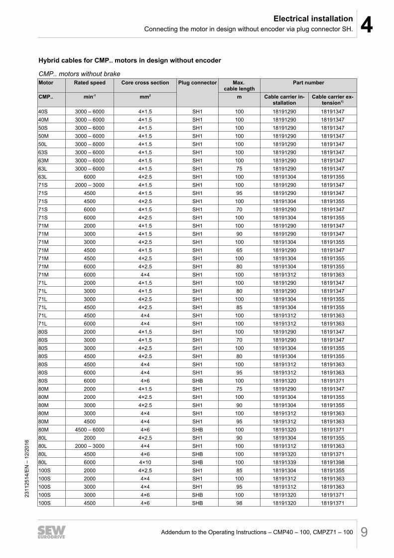
Hybrid cables for CMP.. motors in design without encoder
CMP.. motors without brakeMotor Rated speed Core cross section Plug connector Max.
cable lengthPart number
CMP.. min-1 mm2 m Cable carrier in-stallation
Cable carrier ex-tension1)
40S 3000 – 6000 4×1.5 SH1 100 18191290 1819134740M 3000 – 6000 4×1.5 SH1 100 18191290 1819134750S 3000 – 6000 4×1.5 SH1 100 18191290 1819134750M 3000 – 6000 4×1.5 SH1 100 18191290 1819134750L 3000 – 6000 4×1.5 SH1 100 18191290 1819134763S 3000 – 6000 4×1.5 SH1 100 18191290 1819134763M 3000 – 6000 4×1.5 SH1 100 18191290 1819134763L 3000 – 6000 4×1.5 SH1 75 18191290 1819134763L 6000 4×2.5 SH1 100 18191304 1819135571S 2000 – 3000 4×1.5 SH1 100 18191290 1819134771S 4500 4×1.5 SH1 95 18191290 1819134771S 4500 4×2.5 SH1 100 18191304 1819135571S 6000 4×1.5 SH1 70 18191290 1819134771S 6000 4×2.5 SH1 100 18191304 1819135571M 2000 4×1.5 SH1 100 18191290 1819134771M 3000 4×1.5 SH1 90 18191290 1819134771M 3000 4×2.5 SH1 100 18191304 1819135571M 4500 4×1.5 SH1 65 18191290 1819134771M 4500 4×2.5 SH1 100 18191304 1819135571M 6000 4×2.5 SH1 80 18191304 1819135571M 6000 4×4 SH1 100 18191312 1819136371L 2000 4×1.5 SH1 100 18191290 1819134771L 3000 4×1.5 SH1 80 18191290 1819134771L 3000 4×2.5 SH1 100 18191304 1819135571L 4500 4×2.5 SH1 85 18191304 1819135571L 4500 4×4 SH1 100 18191312 1819136371L 6000 4×4 SH1 100 18191312 1819136380S 2000 4×1.5 SH1 100 18191290 1819134780S 3000 4×1.5 SH1 70 18191290 1819134780S 3000 4×2.5 SH1 100 18191304 1819135580S 4500 4×2.5 SH1 80 18191304 1819135580S 4500 4×4 SH1 100 18191312 1819136380S 6000 4×4 SH1 95 18191312 1819136380S 6000 4×6 SHB 100 18191320 1819137180M 2000 4×1.5 SH1 75 18191290 1819134780M 2000 4×2.5 SH1 100 18191304 1819135580M 3000 4×2.5 SH1 90 18191304 1819135580M 3000 4×4 SH1 100 18191312 1819136380M 4500 4×4 SH1 95 18191312 1819136380M 4500 – 6000 4×6 SHB 100 18191320 1819137180L 2000 4×2.5 SH1 90 18191304 1819135580L 2000 – 3000 4×4 SH1 100 18191312 1819136380L 4500 4×6 SHB 100 18191320 1819137180L 6000 4×10 SHB 100 18191339 18191398100S 2000 4×2.5 SH1 85 18191304 18191355100S 2000 4×4 SH1 100 18191312 18191363100S 3000 4×4 SH1 95 18191312 18191363100S 3000 4×6 SHB 100 18191320 18191371100S 4500 4×6 SHB 98 18191320 18191371
2311
2514
/EN
– 1
2/20
16

4 Electrical installationConnecting the motor in design without encoder via plug connector SH.
Addendum to the Operating Instructions – CMP40 – 100, CMPZ71 – 10010
Motor Rated speed Core cross section Plug connector Max. cable length
Part number
CMP.. min-1 mm2 m Cable carrier in-stallation
Cable carrier ex-tension1)
100S 4500 4×10 SHB 100 18191339 18191398100M 2000 4×2.5 SH1 75 18191304 18191355100M 2000 4×4 SH1 100 18191312 18191363100M 3000 4×4 SH1 85 18191312 18191363100M 3000 4×6 SHB 100 18191320 18191371100M 4500 4×6 SHB 90 18191320 18191371100M 4500 4×10 SHB 100 18191339 18191398100L 2000 4×6 SHB 100 18191320 18191371100L 3000 4×6 SHB 90 18191320 18191371100L 3000 4×10 SHB 100 18191339 18191398100L 4500 4×10 SHB 98 18191339 181913981) Currently only cable carrier extension cables are offered
2311
2514
/EN
– 1
2/20
16

4Electrical installationConnecting the motor in design without encoder via plug connector SH.
Addendum to the Operating Instructions – CMP40 – 100, CMPZ71 – 100 11
CMP.. motors with brakeMotor Rated speed Brake Core cross section Plug con-
nectorMax.
cable lengthPart number
CMP.. min-1 mm2 m Cable carrier in-stallation
Cable carrierextension1)
40S 3000 – 6000 BK 4×1.5 + 3×1 SH1 100 18191290 1819134740M 3000 – 6000 BK 4×1.5 + 3×1 SH1 100 18191290 1819134750S 3000 – 6000 BK 4×1.5 + 3×1 SH1 100 18191290 1819134750M 3000 – 6000 BK 4×1.5 + 3×1 SH1 100 18191290 1819134750L 3000 – 6000 BK 4×1.5 + 3×1 SH1 100 18191290 1819134763S 3000 – 6000 BK 4×1.5 + 3×1 SH1 100 18191290 1819134763M 3000 – 6000 BK 4×1.5 + 3×1 SH1 100 18191290 1819134763L 3000 – 6000 BK 4×1.5 + 3×1 SH1 75 18191290 1819134763L 6000 BK 4×2.5 + 3×1 SH1 100 18191304 1819135571S 2000 – 4500 BP 4×1.5 + 3×1 SH1 80 18191290 1819134771S 4500 BP 4×2.5 + 3×1 SH1 80 18191304 1819135571S 6000 BP 4×1.5 + 3×1 SH1 70 18191290 1819134771S 6000 BP 4×2.5 + 3×1 SH1 80 18191304 1819135571M 2000 – 3000 BP 4×1.5 + 3×1 SH1 80 18191290 1819134771M 3000 BP 4×2.5 + 3×1 SH1 80 18191304 1819135571M 4500 BP 4×1.5 + 3×1 SH1 65 18191290 1819134771M 4500 – 6000 BP 4×2.5 + 3×1 SH1 80 18191304 1819135571M 6000 BP 4×4 + 3×1 SH1 80 18191312 1819136371L 2000 – 3000 BP 4×1.5 + 3×1 SH1 80 18191290 1819134771L 3000 – 4500 BP 4×2.5 + 3×1 SH1 80 18191304 1819135571M 4500 – 6000 BP 4×4 + 3×1 SH1 80 18191312 1819136380S 2000 – 3000 BP 4×1.5 + 3×1 SH1 55 18191290 1819134780S 3000 – 4500 BP 4×2.5 + 3×1 SH1 55 18191304 1819135580S 4500 BP 4×4 + 3×1 SH1 55 18191312 1819136380M 2000 BP 4×1.5 + 3×1 SH1 55 18191290 1819134780M 2000 – 3000 BP 4×2.5 + 3×1 SH1 55 18191304 1819135580M 3000 – 4500 BP 4×4 + 3×1 SH1 55 18191312 1819136380M 4500 BP 4×6 + 3×1.5 SHB 85 18191320 1819137180L 2000 BP 4×2.5 + 3×1 SH1 55 18191304 1819135580L 2000 – 3000 BP 4×4 + 3×1 SH1 55 18191312 1819136380L 4500 BP 4×6 + 3×1.5 SHB 85 18191320 18191371100S 2000 BP 4×2.5 + 3×1 SH1 45 18191304 18191355100S 2000 – 3000 BP 4×4 + 3×1 SH1 45 18191312 18191363100S 3000 – 4500 BP 4×6 + 3×1.5 SHB 70 18191320 18191371100S 4500 BP 4×10 + 3×1.5 SHB 70 18191339 18191398100M 2000 BP 4×2.5 + 2×1 SH1 45 18191304 18191355100M 2000 – 3000 BP 4×4 + 2×1 SH1 45 18191312 18191363100M 3000 – 4500 BP 4×6 + 3×1.5 SHB 70 18191320 18191371100M 4500 BP 4×10 + 3×1.5 SHB 70 18191339 18191398100L 2000 – 3000 BP 4×6 + 3×1.5 SHB 70 18191320 18191371100L 3000 – 4500 BP 4×10 + 3×1.5 SHB 70 18191339 181913981) Currently only cable carrier extension cables are offered
2311
2514
/EN
– 1
2/20
16

4 Electrical installationConnecting the motor in design without encoder via plug connector SH.
Addendum to the Operating Instructions – CMP40 – 100, CMPZ71 – 10012
CMPZ.. motors without brakeMotor Rated speed Core cross section Plug con-
nectorMax.
cable lengthPart number
CMPZ.. min-1 mm2 m Cable carrier installa-tion
Cable carrier exten-sion1)
71S 2000 – 3000 4×1.5 + 3×1 SH1 100 18191290 1819134771S 4500 4×1.5 + 3×1 SH1 96 18191290 1819134771S 4500 4×2.5 + 3×1 SH1 100 18191304 1819135571S 6000 4×1.5 + 3×1 SH1 73 18191290 1819134771S 6000 4×2.5 + 3×1 SH1 100 18191304 1819135571M 2000 4×1.5 + 3×1 SH1 100 18191290 1819134771M 3000 4×1.5 + 3×1 SH1 93 18191290 1819134771M 3000 4×2.5 + 3×1 SH1 100 18191304 1819135571M 4500 4×1.5 + 3×1 SH1 64 18191290 1819134771M 4500 4×2.5 + 3×1 SH1 100 18191304 1819135571M 6000 4×2.5 + 3×1 SH1 79 18191304 1819135571M 6000 4×4 + 3×1 SH1 100 18191312 1819136371L 2000 4×1.5 + 3×1 SH1 100 18191290 1819134771L 3000 4×1.5 + 3×1 SH1 74 18191290 1819134771L 3000 4×2.5 + 3×1 SH1 100 18191304 1819135571L 4500 4×2.5 + 3×1 SH1 83 18191304 1819135571L 4500 – 6000 4×4 + 3×1 SH1 100 18191312 1819136380S 2000 4×1.5 + 3×1 SH1 100 18191290 1819134780S 3000 4×1.5 + 3×1 SH1 70 18191290 1819134780S 3000 4×2.5 + 3×1 SH1 100 (75) 18191304 1819135580S 4500 4×2.5 + 3×1 SH1 76 (75) 18191304 1819135580S 6000 4×4 + 3×1 SH1 100 (75) 18191312 1819136380M 2000 4×1.5 + 3×1 SH1 75 18191290 1819134780M 2000 4×2.5 + 3×1 SH1 100 18191304 1819135580M 3000 4×2.5 + 3×1 SH1 87 (75) 18191304 1819135580M 3000 4×4 + 3×1 SH1 100 (75) 18191312 1819136380M 4500 4×4 + 3×1 SH1 93 (75) 18191312 1819136380M 4500 4×6 + 3×1.5 SHB 100 18191320 1819137180L 2000 4×2.5 + 3×1 SH1 93 18191304 1819135580L 2000 4×4 + 3×1 SH1 100 18191312 1819136380L 3000 4×4 + 3×1 SH1 100 (75) 18191312 1819136380L 4500 4×6 + 3×1.5 SHB 100 18191320 18191371100S 2000 4×2.5 + 3×1 SH1 88 18191304 18191355100S 2000 4×4 + 3×1 SH1 100 18191312 18191363100S 3000 4×4 + 3×1 SH1 95 (55) 18191312 18191363100S 3000 4×6 + 3×1.5 SHB 100 (80) 18191320 18191371100S 4500 4×6 + 3×1.5 SHB 93 (80) 18191320 18191371100S 4500 4×10 + 3×1.5 SHB 100 (80) 18191339 18191398100M 2000 4×2.5 + 3×1 SH1 79 18191304 18191355100M 2000 4×4 + 3×1 SH1 100 18191312 18191363100M 3000 4×4 + 3×1 SH1 85 (55) 18191312 18191363100M 3000 4×6 + 3×1.5 SHB 100 (80) 18191320 18191371100M 4500 4×6 + 3×1.5 SHB 84 (80) 18191320 18191371100M 4500 4×10 + 3×1.5 SHB 100 (80) 18191339 18191398100L 2000 4×4 + 3×1 SH1 85 18191312 18191363100L 2000 4×6 + 3×1.5 SHB 100 18191320 18191371100L 3000 4×6 + 3×1.5 SHB 87 (80) 18191320 18191371100L 3000 4×10 + 3×1.5 SHB 100 (80) 18191339 18191398100L 4500 4×10 + 3×1.5 SHB 96 (80) 18191339 181913981) Currently only cable carrier extension cables are offered 23
1125
14/E
N –
12/
2016

4Electrical installationConnecting the motor in design without encoder via plug connector SH.
Addendum to the Operating Instructions – CMP40 – 100, CMPZ71 – 100 13
CMPZ.. motors with brakeMotor Rated speed Brake Core cross section Plug con-
nectorMax.
cable lengthPart number
CMPZ.. min-1 mm2 m Cable carrier in-stallation
Cable carrierextension1)
71S 2000 – 3000 BY 4×1.5 + 3×1 SH1 100 18191290 1819134771S 4500 BY 4×1.5 + 3×1 SH1 96 18191290 1819134771S 4500 BY 4×2.5 + 3×1 SH1 100 18191304 1819135571S 6000 BY 4×1.5 + 3×1 SH1 73 18191290 1819134771S 6000 BY 4×2.5 + 3×1 SH1 100 18191304 1819135571M 2000 BY 4×1.5 + 3×1 SH1 100 18191290 1819134771M 3000 BY 4×1.5 + 3×1 SH1 93 18191290 1819134771M 3000 BY 4×2.5 + 3×1 SH1 100 18191304 1819135571M 4500 BY 4×1.5 + 3×1 SH1 64 18191290 1819134771M 4500 BY 4×2.5 + 3×1 SH1 100 18191304 1819135571M 6000 BY 4×2.5 + 3×1 SH1 79 18191304 1819135571M 6000 BY 4×4 + 3×1 SH1 100 18191312 1819136371L 2000 BY 4×1.5 + 3×1 SH1 100 18191290 1819134771L 3000 BY 4×1.5 + 3×1 SH1 74 18191290 1819134771L 3000 BY 4×2.5 + 3×1 SH1 100 18191304 1819135571L 4500 BY 4×2.5 + 3×1 SH1 83 18191304 1819135571L 4500 – 6000 BY 4×4 + 3×1 SH1 100 18191312 1819136380S 2000 BY 4×1.5 + 3×1 SH1 100 18191290 1819134780S 3000 BY 4×1.5 + 3×1 SH1 70 18191290 1819134780S 3000 BY 4×2.5 + 3×1 SH1 100 (75) 18191304 1819135580S 4500 BY 4×2.5 + 3×1 SH1 76 (75) 18191304 1819135580S 6000 BY 4×4 + 3×1 SH1 100 (75) 18191312 1819136380M 2000 BY 4×1.5 + 3×1 SH1 75 18191290 1819134780M 2000 BY 4×2.5 + 3×1 SH1 100 18191304 1819135580M 3000 BY 4×2.5 + 3×1 SH1 87 (75) 18191304 1819135580M 3000 BY 4×4 + 3×1 SH1 100 (75) 18191312 1819136380M 4500 BY 4×4 + 3×1 SH1 93 (75) 18191312 1819136380M 4500 BY 4×6 + 3×1.5 SHB 100 18191320 1819137180L 2000 BY 4×2.5 + 3×1 SH1 93 18191304 1819135580L 2000 BY 4×4 + 3×1 SH1 100 18191312 1819136380L 3000 BY 4×4 + 3×1 SH1 100 (75) 18191312 1819136380L 4500 BY 4×6 + 3×1.5 SHB 100 18191320 18191371100S 2000 BY 4×2.5 + 3×1 SH1 88 18191304 18191355100S 2000 BY 4×4 + 3×1 SH1 100 18191312 18191363100S 3000 BY 4×4 + 3×1 SH1 95 (55) 18191312 18191363100S 3000 BY 4×6 + 3×1.5 SHB 100 (80) 18191320 18191371100S 4500 BY 4×6 + 3×1.5 SHB 93 (80) 18191320 18191371100S 4500 BY 4×10 + 3×1.5 SHB 100 (80) 18191339 18191398100M 2000 BY 4×2.5 + 3×1 SH1 79 18191304 18191355100M 2000 BY 4×4 + 3×1 SH1 100 18191312 18191363100M 3000 BY 4×4 + 3×1 SH1 85 (55) 18191312 18191363100M 3000 BY 4×6 + 3×1.5 SHB 100 (80) 18191320 18191371100M 4500 BY 4×6 + 3×1.5 SHB 84 (80) 18191320 18191371100M 4500 BY 4×10 + 3×1.5 SHB 100 (80) 18191339 18191398100L 2000 BY 4×4 + 3×1 SH1 85 18191312 18191363100L 2000 BY 4×6 + 3×1.5 SHB 100 18191320 18191371100L 3000 BY 4×6 + 3×1.5 SHB 87 (80) 18191320 18191371100L 3000 BY 4×10 + 3×1.5 SHB 100 (80) 18191339 18191398100L 4500 BY 4×10 + 3×1.5 SHB 96 (80) 18191339 181913981) Currently only cable carrier extension cables are offered23
1125
14/E
N –
12/
2016

4 Electrical installationConnecting the motor in design without encoder via plug connector SH.
Addendum to the Operating Instructions – CMP40 – 100, CMPZ71 – 10014
Permitted cable lengths for DC 24 V BY working brakes are especially reduced.Note the following guidelines:CMPZ71 with /BY: maximum 8 mCMPZ80 with /BY: 6.4 to 9 m depending on cable cross sectionCMPZ100 with /BY: 4.5 to 7 m depending on cable cross sectionFor project planning with DC 24 V BY working brake, contact SEW‑EURODRIVE.
4.2.2 Prefabricated cablesPrefabricated cables are available from SEW‑EURODRIVE to connect the SH.. plugconnector system.For information on prefabricated cables and part numbers, refer to the document"Latest News - CMP40 – 100, CMPZ71 – 100 Synchronous Servomotors – Designwithout Encoder".
2311
2514
/EN
– 1
2/20
16
4Electrical installationConnecting the motor in design without encoder via plug connector SH.
Addendum to the Operating Instructions – CMP40 – 100, CMPZ71 – 100 15
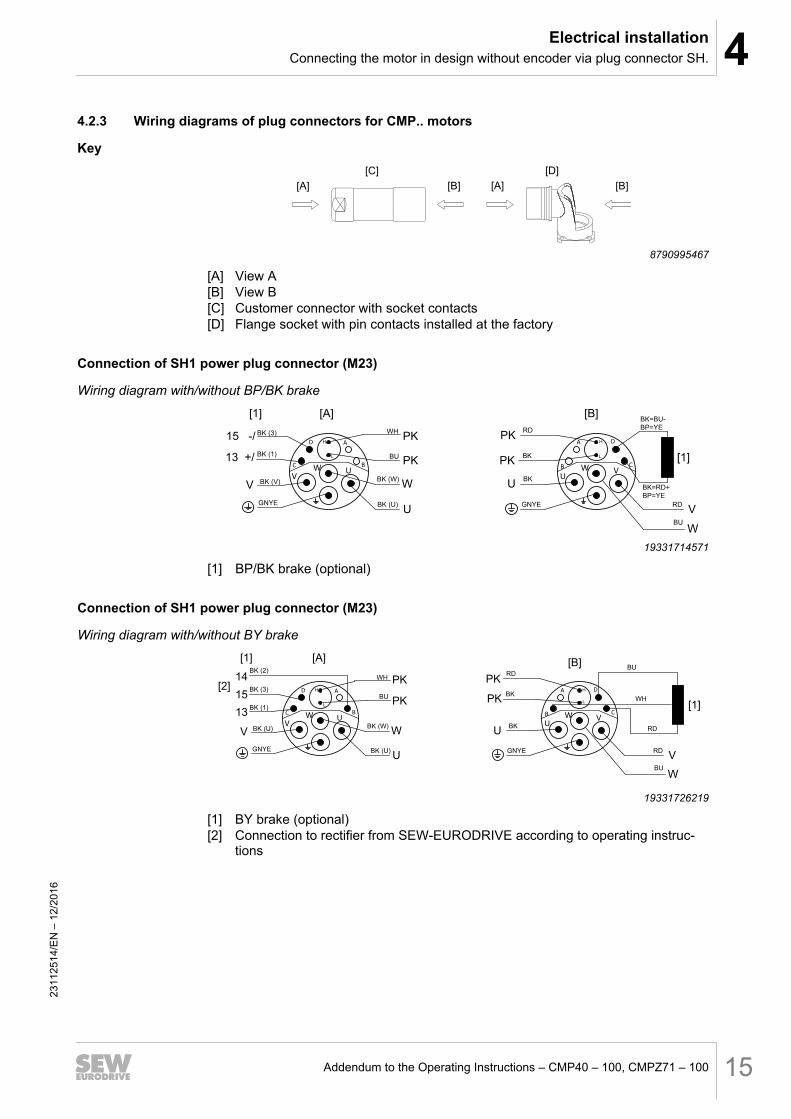
4.2.3 Wiring diagrams of plug connectors for CMP.. motors
Key
[A]
[C]
[B] [A]
[D]
[B]
8790995467
[A] View A[B] View B[C] Customer connector with socket contacts[D] Flange socket with pin contacts installed at the factory
Connection of SH1 power plug connector (M23)
Wiring diagram with/without BP/BK brake
BK=BU-
BP=YE
BK=RD+
BP=YE
RD
GNYE
BK
BKPK
U
[1]BU
BK (3)
BK (W)
GNYE
PK
U
W
PKWH
[1] [A]
PK
[B]
V
D
B
AH
L
C
V
W U
A
C
DH
L
B
U
W V
BK (V)
BK (U) RDV
BK (1)
15 -/
13 +/
BUW
19331714571
[1] BP/BK brake (optional)
Connection of SH1 power plug connector (M23)
Wiring diagram with/without BY brake
BURD
GNYE
BK
BKPK
U
[1]BU
BK (3)
BK (W)
GNYE
PK
U
W
PKWH
[A]
PK
[B]
V
D
B
AH
L
C
V
W U
A
C
DH
L
B
U
W V
BK (U)
BK (U) RDV
BK (1)
15
13
BUW
WH
RD
14BK (2)
[1]
[2]
19331726219
[1] BY brake (optional)[2] Connection to rectifier from SEW‑EURODRIVE according to operating instruc-
tions
2311
2514
/EN
– 1
2/20
16

4 Electrical installationConnecting the motor in design without encoder via plug connector SH.
Addendum to the Operating Instructions – CMP40 – 100, CMPZ71 – 10016
Connection of SHB (M40) power plug connectors
Wiring diagram with/without BP brake
RD
GNYEBU
BKPK
W
[1]
BUBK (3)
BK (1)
GNYE
PK
V
13PKWH
[1] [A]
PK
[B]
BK (U)BK (V)
BKU
15
RDV
W
1+
-
H
L2
U
N
V
-2
1
H
L+
V
W
U
N
BK (W)W
U
YE
YE
[2]
19331737867
[1] BP brake (optional)[2] Connection to rectifier from SEW‑EURODRIVE according to operating instruc-
tions
Connection of SHB (M40) power plug connectors
Wiring diagram with/without BY brake
RD
GNYEBU
BKPK
W
[1]
BU
BK (3)
BK (1)
GNYE
PK
V
13PKWH
[1]
PK
[B]
BK (U)BK (V)
BKU
BK (2)
15
14
RDV
W
1+
-
H
L2
U
N
V
-2
1
H
L+
V
W
U
N
BK (W)W
U
RD
WH
BU
[A]
[2]
19331749515
[1] BY brake (optional)[2] Connection to rectifier from SEW‑EURODRIVE according to operating instruc-
tions. For BY.D connection 14 is omitted.
2311
2514
/EN
– 1
2/20
16

4Electrical installationConnecting the motor in design without encoder via plug connector SH.
Addendum to the Operating Instructions – CMP40 – 100, CMPZ71 – 100 17
Wiring diagrams of the brake control – BP brakeIn every application, the BP holding brake can be controlled via the BMV brake relayor a customer relay with varistor overvoltage protection.If the system complies with the specifications for direct brake control, then a BP brakecan also be controlled directly via the brake output of a MOVIDRIVE® modular applica-tion inverter.However, the brakes of motors CMP.80 and CMP.100 can never be directly connec-ted to MOVIDRIVE® modular. For detailed information, refer to the "MOVIDRIVE®
modular Application Inverter" technology manual.
BMV brake controller
BMV
K12
1 2 3 4 13
14
15
BMV
1 2 3 4 13
14
15
+ -
K12
+ -U
DC 24 V
IN
DC 24 VU
DC 24 V
IN
DC 24 V
SH1[A]
D
B
AH
L
C
V
W U W
1+
-
H
L2
U
N
V
SHB[A]
+ -
BK3
BK1 +
-
+ -
BK3
BK1
+-
19331763339
Connection 1, 2 Power supplyConnection 3, 4 Signal (inverter)
2311
2514
/EN
– 1
2/20
16

4 Electrical installationConnecting the motor in design without encoder via plug connector SH.
Addendum to the Operating Instructions – CMP40 – 100, CMPZ71 – 10018
Direct 24 V brake supply with non-SEW inverters
If the brake is not controlled via BMV brake control unit, a contactor must be used thatis suitable for switching inductive DC loads. In this case a varistor circuit in parallel tothe brake coil is required as overvoltage protection and EMC interference suppressionof the 24 V supply. For brakes with external DC supply of more than 24 V and withoutBMV, a 300 V varistor must be used.Additional option: If the varistor circuit is not sufficient for EMC interference suppres-sion, an additional RC element can be switched via the contactor.
+DC 24 V
[2]
[1]
SHB
[A]
W
1+
-H
L2
U
N
V
-
[1]
[2]
D
B
AH
L
C
VW U
- +
DC 24 V
SH1
[A]
19331774987
[1] Varistor[2] RC element
Direct brake supply
with MOVIDRIVE®
modular
SH1
DC 24 V
DGND DBØØ
-
+
D
B
AH
L
C
V
W U
[A]
19331788299
2311
2514
/EN
– 1
2/20
16

4Electrical installationConnecting the motor in design without encoder via plug connector SH.
Addendum to the Operating Instructions – CMP40 – 100, CMPZ71 – 100 19
Wiring diagrams of the brake control – BK brakeIn every application, the BK holding brake can be controlled via the BMV brake relayor a customer relay with varistor overvoltage protection.If the system complies with the specifications for direct brake control, then a BK brakecan also be controlled directly via the brake output of a MOVIDRIVE® modular applica-tion inverter.For detailed information, refer to the "MOVIDRIVE® modular Application Inverter" tech-nology manual.
BMV brake controller
BMV
1 2 3 4 13
14
15
SH1
K12
+ -U
DC 24 V
IN
DC 24 V
+ -+ -
D
B
AH
L
C
V
W U
[A]
+
-BK3
BK1
19331813515
Connection 1, 2 Power supplyConnection 3, 4 Signal (inverter)
2311
2514
/EN
– 1
2/20
16

4 Electrical installationConnecting the motor in design without encoder via plug connector SH.
Addendum to the Operating Instructions – CMP40 – 100, CMPZ71 – 10020
Direct 24 V brake supply with non-SEW inverters
If the brake is not controlled via BMV brake control unit, a contactor must be used thatis suitable for switching inductive DC loads. In this case a varistor circuit in parallel tothe brake coil is required as overvoltage protection and EMC interference suppressionof the 24 V supply. For brakes with external DC supply of more than 24 V and withoutBMV, a 300 V varistor must be used.Additional option: If the varistor circuit is not sufficient for EMC interference suppres-sion, an additional RC element can be switched via the contactor.
+DC 24 V
[2]
[1]
SHB
[A]
W
1+
-H
L2
U
N
V
-
[1]
[2]
D
B
AH
L
C
VW U
- +
DC 24 V
SH1
[A]
19331774987
[1] Varistor[2] RC element
Direct 24 V brake supply
with MOVIDRIVE®
modular
SH1
DC 24 V
DGND DBØØ
-
+
D
B
AH
L
C
V
W U
[A]
19331788299
NOTICEDamage to the BK brake.Possible damage to property.• It is essential that you observe the correct polarity of BK brake supply. Check the
polarity when replacing the brake.
2311
2514
/EN
– 1
2/20
16

4Electrical installationConnecting the motor in design without encoder via plug connector SH.
Addendum to the Operating Instructions – CMP40 – 100, CMPZ71 – 100 21
Wiring diagrams of the brake control – BY brake
BME brake rectifier
Cut-off in the AC circuit / standard application of the brake with SH1, SHB.
K12
UAC
1 2 3 4 13
14
15
K12
UAC
1 2 3 4 13
14
15
D
B
AH
L
C
V
W UW
1+
-
H
L2
U
N
V
SH1[A]
BME BME
SHB [A]SH1
BK1
BK3
BK2
BK1
BK3
BK2
19331826571
Cut-off in the DC and AC circuits / rapid application of the brake with SH1, SHB.
K12
UAC
1 2 3 4 13
14
15
K12
UAC
1 2 3 4 13
14
15
D
B
AH
L
C
V
W U
SH1[A]
W
1+
-
H
L2
U
N
V
SHB [A]
BME BME
BK1
BK3
BK2
BK1
BK3
BK2
19331838475
BMP brake rectifier
Cut-off in the DC and AC circuits / rapid application of the brake / integrated voltagerelay with SH1 and SHB.
K12
UAC
1 2 3 4 13
14
15
K12
UAC
1 2 3 4 13
14
15
D
B
AH
L
C
V
W UW
1+
-
H
L2
U
N
V
SH1[A]
BMP BMP
SHB [A]
BK1
BK3
BK2
BK1
BK3
BK2
193318503792311
2514
/EN
– 1
2/20
16
4 Electrical installationConnecting the motor in design without encoder via plug connector SH.
Addendum to the Operating Instructions – CMP40 – 100, CMPZ71 – 10022
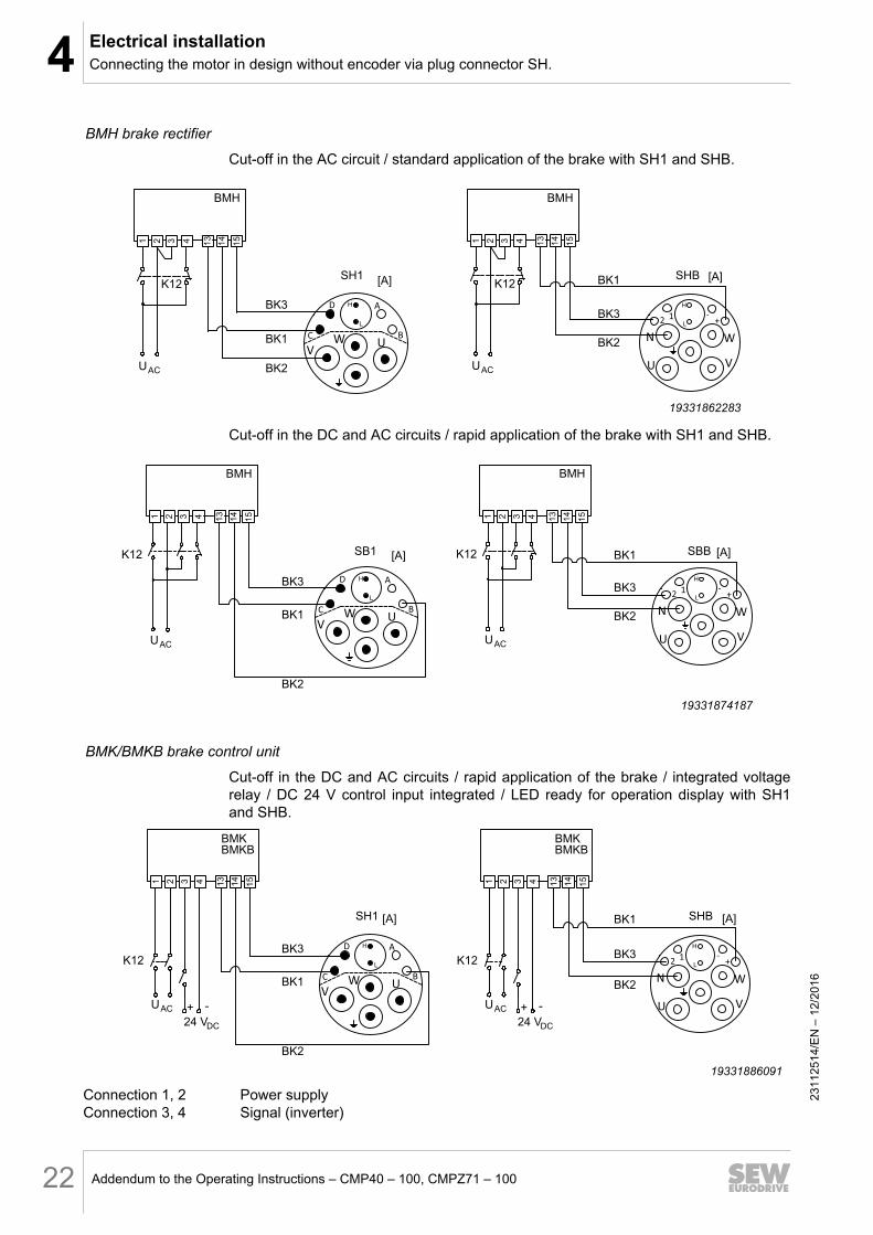
BMH brake rectifier
Cut-off in the AC circuit / standard application of the brake with SH1 and SHB.
BMH
K12
UAC
1 2 3 4 13
14
15
BMH
1 2 3 4 13
14
15
SHBK12
UAC
D
B
AH
L
C
V
W UW
1+
-
H
L2
U
N
V
SH1 [A] [A]
BK1
BK3
BK2
BK1
BK3
BK2
19331862283
Cut-off in the DC and AC circuits / rapid application of the brake with SH1 and SHB.
BMH
K12
UAC
1 2 3 4 13
14
15
SB1
BMH1 2 3 4 13
14
15
SBBK12
UAC
W
1+
-
H
L2
U
N
V
D
B
AH
L
C
V
W U
[A] [A]
BK1
BK3
BK2
BK1
BK3
BK2
19331874187
BMK/BMKB brake control unit
Cut-off in the DC and AC circuits / rapid application of the brake / integrated voltagerelay / DC 24 V control input integrated / LED ready for operation display with SH1and SHB.
BMK
K12
UAC
1 2 3 4 13
14
15
SH1
1 2 3 4 13
14
15
SHB
+ -
24 VDC
K12
UAC + -
24 VDC
D
B
AH
L
C
V
W UW
1+
-
H
L2
U
N
V
[A] [A]
BK1
BK3
BK2
BK1
BK3
BK2
BMKBBMKBMKB
19331886091
Connection 1, 2 Power supplyConnection 3, 4 Signal (inverter)
2311
2514
/EN
– 1
2/20
16

4Electrical installationConnecting the motor in design without encoder via plug connector SH.
Addendum to the Operating Instructions – CMP40 – 100, CMPZ71 – 100 23
BMV brake controller
Cut-off in the DC and AC circuits / rapid application of the brake / DC 24 V control in-put integrated with SH1, SHB.
24 VDC24 VDC
BMV
K12
1 2 3 4 13
14
15
SH1
BMV
1 2 3 4 13
14
15
SHB
+ -
24 VDC
K12
+ -
24 VDC
D
B
AH
L
C
V
W UW
1+
-
H
L2
U
N
V
[A] [A]
BK1
BK3
BK2
BK1
BK3
BK2
19331897995
Connection 1, 2 Power supplyConnection 3, 4 Signal (inverter)
2311
2514
/EN
– 1
2/20
16

4 Electrical installationOptions
Addendum to the Operating Instructions – CMP40 – 100, CMPZ71 – 10024
4.3 Options4.3.1 PT1000 thermal motor protection
Type designation/PK
DescriptionThermal motor protection in combination with the corresponding evaluation electronicsprevents the motor from overheating and consequently from being damaged. A tem-perature sensor provides only indirect protection as only one sensor value is determ-ined.The /PK design consists of a platinum sensor PT1000 installed in one of the three mo-tor windings. Unlike the /KY semiconductor sensor, the platinum sensor has an almostlinear characteristic curve and is more accurate. The frequency inverter can take onthe function of motor protection via the /PK, when it is used in combination with a fre-quency inverter containing the thermal motor model.
Technical dataThe PT1000 temperature sensor continuously detects the motor temperature.
PT1000Connection red – black
Total resistance at 20 – 25 °C 1050 Ω < R < 1150 Ω
Test current < 3 mA
INFORMATIONThe temperature sensor is unipolar which means that interchanging the incomingcables does not change the measurement result.
Typical characteristic curve of PT1000, F0.6
0
200
400
600
800
1000
1200
1400
1600
1800
2000
-50 0 50 100 150 200
[Ω]
[°C]
2311
2514
/EN
– 1
2/20
16


SEW-EURODRIVE—Driving the world
SEW-EURODRIVE GmbH & Co KGP.O. Box 302376642 BRUCHSALGERMANYPhone +49 7251 75-0Fax +49 7251 [email protected]