advanced combustion and emission control techical team … · 2014-02-21 · advanced combustion...
TRANSCRIPT

Hydrogen Storage Technologies Roadmap
Advanced Combustion and Emission Control Technical Team Roadmap June 2013
This roadmap is a document of the US DRIVE Partnership US DRIVE (Driving Research and Innovation for Vehicle efficiency and Energy sustainability) is a voluntary non‐binding and nonlegal partnership among the US Department of Energy USCAR representing Chrysler Group LLC Ford Motor Company and General Motors Tesla Motors five energy companies mdash BP America Chevron Corporation Phillips 66 Company ExxonMobil Corporation and Shell Oil Products US two utilities mdash Southern California Edison and DTE Energy and the Electric Power Research Institute (EPRI)
The Advanced Combustion and Emission Control Technical Team is one of 12 US DRIVE technical teams (ldquotech teamsrdquo) whose mission is to accelerate the development of pre‐competitive and innovative technologies to enable a full range of efficient and clean advanced light‐duty vehicles as well as related energy infrastructure
For more information about US DRIVE please see the US DRIVE Partnership Plan wwwvehiclesenergygovaboutpartnershipsusdrivehtml or wwwuscarorg
Advanced Combustion and Emission Control Tech Team Roadmap
Table of Contents Introduction 1
Low-Temperature Combustion (LTC) 1 Dilute Gasoline Combustion 2 Clean Diesel Combustion 2 Fuels Utilization 2
The Current Baseline Production Powertrain Technology 2 Fuel Economy and Emission Regulations and Trends 3
Fuel Economy 3 Emissions 4
State of Advanced Powertrain Technologies 4 Low-Temperature Combustion 4 Dilute Gasoline Combustion 5 Clean Diesel Combustion 7 Parasitic Loss Reduction and Waste Heat Recovery 8
Goals 8 Technological Pathways to Increases in Engine Efficiency 8 Engine Speeds and Loads for Efficiency Testing and Reporting 9 Baseline Engine Efficiencies 11 Goals for Engine Efficiency Increases 11 Goals for Aftertreatment to Enable Advanced Combustion Emission Compliance 12
BarriersTechnical Strategies 13 Low-Temperature Combustion 13 Dilute Gasoline Combustion 17 Clean Diesel Combustion 21 Parasitic Loss Reduction and Waste Heat Recovery 24 Cross-Cutting TechnologiesApproaches for Enabling Goals 25 Powertrain Systems Integration for Enabling Goals 26
Cost Strategy Discussions 27 Research Leveraging with Other DOE Activities 28
Vehicle Technologies Office (VT) 28 Office of Science Basic Energy Sciences (BES) Activities 29
Appendix A Hydrogen-Fueled Engines A-1 The Current Baseline Production Powertrain Technology A-1
Hydrogen-fueled SI Engines A-1 BarriersTechnical Strategies A-2
Hydrogen-fueled SI Engines A-2
iii
Advanced Combustion and Emission Control Tech Team Roadmap
Figure Figure 1 Technology Pathways to Improving Engine Efficiency and the Selected
Operating Conditions for Evaluating Efficiency Improvements 10
Table Table 1 Engine Efficiency Baselines and Goals for Multi‐cylinder Engines 12
iv
Advanced Combustion and Emission Control Tech Team Roadmap
Introduction The Advanced Combustion and Emission Control (ACEC) Technical Team is focused on removing technical barriers to the commercialization of advanced high-efficiency emission-compliant internal combustion (IC) engines for light-duty vehicle powertrains (ie passenger car minivan SUV and pickup trucks)1 Elimination of the technical barriers will enable light-duty engines with significantly higher fuel efficiency than current conventional port-fuel-injected (PFI) engines dominating the road today Increasing the efficiency of internal combustion engines is a technologically proven and cost effective approach to dramatically improving the fuel economy of the nationrsquos fleet of vehicles in the near- to mid-term with the corresponding benefits of reducing our dependence on foreign oil and reducing carbon emissions Efficiency can be increased by improving combustion processes minimizing engine losses such as friction reducing the energy penalty of the emission control system and using recovered waste energy in propulsion Compliance with exhaust emission regulations will be mandated and requires aftertreatment technologies integrated with the engine combustion approaches Fuels under consideration include hydrocarbon-based fuels (petroleum- and non-petroleum-based and gaseous fuels such as natural gas) Because of their relatively low cost high performance and ability to utilize renewable fuels internal combustion engines including those in hybrid vehicles will continue to be critical to our transportation infrastructure for decades The ACEC Technical Team efforts support the US DRIVE Partnership goal to ldquosignificantly improve the efficiency of vehicles powered by advanced internal combustion powertrains (including hybrids) and vehicle fuel systems while protecting the environmentrdquo As will be discussed the ACEC 2020 USDRIVE research target is as follows ldquoA 20 improvement in engine efficiency compared to a 2010 baseline Engine concepts shall be commercially viable and meet 2020 emissions standardsrdquo The ACEC focuses on advanced engine and aftertreatment technology for three major combustion strategies (1) Low-Temperature Combustion (2) Dilute Gasoline Combustion and (3) Clean Diesel Combustion Each of the above strategies are defined and introduced in the following subsections The advanced engine technology with the above strategies will most likely result in lower exhaust temperatures that are not compatible with conventional aftertreatment systems Thus appropriate advanced aftertreatment technology for the lower temperature exhaust environments is included as an integral part of the roadmap In addition waste heat recovery strategies to improve efficiency are included The final subsection of the roadmap discusses the very synergistic role that fuel utilization RampD plays with combustion strategies Low-Temperature Combustion (LTC) This novel strategy involves the flameless staged burning of the fuel in the combustion chamber at low temperatures LTC offers potential for achieving efficiencies as high as or higher than diesel engine combustion approaches Moreover an additional major attraction of LTC is its simultaneous potential for dramatically lower engine-out emissions and hence lower aftertreatment costs The LTC strategy has many variants (eg Homogeneous Charge Compression Ignition (HCCI) Partially-premixed Charge Compression Ignition (PCCI) etc) that are characterized by the degree of fuel-air mixing prior to the start of combustion Engines operating under LTC are attractive for light-duty applications because current research suggests they offer the highest engine fuel efficiency potential possible relative to current PFI gasoline engines dominating the road Although these technologies offer low engine out emissions they create significant aftertreatment challenges due to reduced exhaust temperatures in addition to the existing emission challenge during the cold-start
1 In this roadmap light-duty vehicles include Department of Transportation vehicle classes 1 and 2 and correspond
to gross vehicle weights less than 10000 lbs These vehicles meet US CAFECO2 and emission regulations
1
Advanced Combustion and Emission Control Tech Team Roadmap
Dilute Gasoline Combustion This strategy involves advanced efficient combustion of gasoline fuel which is dominated by the propagation of a flame through fuel and air that is largely premixed The efficiency gain is achieved through advanced combustion of dilute gasoline-air mixtures Even though engines employing flame-propagation combustion have been produced for more than a century they still have significant potential to contribute to fuel efficiency gains through elimination of part-load efficiency losses A key attraction of this strategy is its relatively small increase in complexity and cost Market analysts forecast that gasoline-fueled engines will continue to be the most-used option in the passenger car market in the United States for several decades and as a result will account for the largest fraction of fuel consumption In this roadmap ethanol (as E85) and natural gas combustion are included in this strategy because many physical properties of combustion are similar although fuel infrastructure and some hydrocarbon fuel specific emission challenges exist
Clean Diesel Combustion This strategy involves techniques for the clean advanced combustion of diesel fuel where burning predominantly takes place simultaneously with the mixing of fuel and air known as diffusion combustion Automotive diesel combustion enables very efficient engine architecture and is the key motivation behind this strategy Clean diesel engines reduce emissions via advanced diesel combustion and advanced aftertreatment systems Diesel engines are most popular for medium and heavy-duty applications1 but currently have a low penetration in light-duty vehicles Diesel engines are attractive for light-duty applications because they offer engine thermal efficiencies that are among the best possible (eg up to 33 higher peak thermal efficiency than the PFI engines dominating the road today) The combustion strategy has cross-cut linkages with heavy-duty engine manufacturers for maximum synergy
Fuels Utilization The ACEC powertrain RampD efforts are intended to be compatible with current and future hydrocarbon-based fuels (petroleum and non-petroleum) and gaseous (hydrogen and natural gas) fuels The ACEC research is conducted in coordination with DOE Vehicle Technologies Program fuel utilization research The fuel utilization RampD has two overall goals One goal is to reduce our nationrsquos dependence on petroleum for transportation by conducting RampD to enhance the use of drop-in fuels2 from alternative sources especially low-carbon fuel sources The second goal is to determine fuel characteristics that enable current and emerging advanced combustion engines and aftertreatment systems that meet program objectives Achieving these goals will require a greater understanding of how new drop-in fuels will impact advanced combustion strategies and aftertreatment systems in addition to identifying practical economic fuels and fuel-blending components with potential to directly displace significant amounts of petroleum
The Current Baseline Production Powertrain Technology Since 2000 the annual sales volume of light-duty vehicles ranged from 92 to 165 million vehicles with economic conditions strongly influencing the annual sales Nearly all light-duty vehicles are currently powered by internal combustion engines (ICEs) The ACEC Tech Team considers the ICE as the dominant propulsion system today and for many decades into the future ICEs are used in vehicles with manual and automatic transmissions hybrid plug-in hybrids and range-extended electric vehicles The only vehicles without an ICE are battery electric vehicles (BEV) and fuel cell vehicles (FCV) In 2010 an extremely limited number of BEV and FCV powered vehicles were available and were concentrated in regions with charging or hydrogen fueling infrastructure The volume of these non-ICE vehicles could
1 Medium- and heavy-duty vehicles have gross vehicle weight greater than 10000 lbs 2 Fuels from alternative sources that are chemically equivalent to petroleum fuels
2
Advanced Combustion and Emission Control Tech Team Roadmap
increase in the future depending on customer demand availability of technology cost of fuel and alternative vehicle cost compared to an ICE vehicle
The ICE in light-duty vehicles is either spark ignited (SI) or diesel with SI engine technology dominating in the United States Since 2000 the annual penetration of light-duty vehicles with diesel engines was 3 to 4 Trucks designed mainly for commercial use with gross vehicle weight (GVW) greater than 8500 lbs represented the majority of diesel applications The diesel penetration in cars and trucks less than 8500 lbs designed mainly for personal transportation was 05 in 2010 Because of these demographics the ACEC baseline is focused on vehicles with GVW less than 8500 lbs using an SI engine
The most common SI ICE configuration in the United States in this size class is the multi-valve port fuel injection (PFI) stoichiometric gasoline-fuelled engine with Variable Valve Timing (VVT) and Three-Way Catalyst (TWC) aftertreatment technology3 Based on its popularity the ACEC team has chosen this as the baseline engine configuration Multi-valve refers to 3- or 4-valves per cylinder to increase air flow and engine torque The VVT strategies commonly used change the phasing of intake andor exhaust valves relative to the crank shaft to increase internal EGR reduce pumping and optimize combustion for improved performance and efficiency In 2010 86 of vehicles had engines with some form of VVT (also referred to as cam phasing) technology5 The penetration of this overall SI technology has increased steadily over the last 20 years PFI refers to injection of fuel into the intake port in a manner that a stoichiometric mixture of fuel and air is inducted into the cylinder during the intake stroke In 2010 91 of vehicles used PFI engines All TWC technologies require a stoichiometric fueling strategy and close coordination with engine operation The engineTWC control system uses heated O2 sensors and sequential fuel injection to achieve high catalyst efficiency While most of these vehicles are currently certified at Bin 4 or 5 this technology strategy is achieving Tier 2 Bin 2 emission levels
Fuel Economy and Emission Regulations and Trends
Fuel Economy Light-duty-vehicle fuel economy regulations are now in place to 2025 The current regulations require a US fleet average of 250-g CO2 per mile in 2016 (equivalent to 355 miles per gallon) and 163-g CO2 per mile in 2025 (equivalent to 545 miles per gallon) This is a 40 increase and more than a 100 increase in miles per gallon versus a 2008 baseline of 25 miles per gallon for 2016 and 2025 respectively Each manufacturer has a different fuel economy target depending on the vehicle mix and volume sold and each vehicle has a fuel economy target based on the vehicle footprint4
Manufacturers do not assume that the engine alone will provide the necessary corporate average fuel economy (CAFE) improvements Instead a combination of technologies at a vehicle level will be used to meet the regulation Customer demand will play a role in technology selection Technology areas that will improve CAFE include Engine (dilute gasoline clean diesel LTC boosting and downsizing and other advanced fuel
injection and combustion approaches) Transmission (automatic manual dual clutch etc)
3 If properly designed this engine can operate with blends of ethanol and gasoline up to 85 ethanol or with gaseous fuels such as natural gas and petroleum gas
4 Credits for other CO2 reduction technologies and business decisions can reduce the CAFE target Examples of these credit and incentive opportunities are reduced refrigerant leakage from air conditioner flex fuel (credit declines to zero in 2016) BEV PHEV and fuel cell vehicles natural gas vehicles credit transfer between cartruck fleets or futureprevious model years credits purchased from other OEMs
3
Advanced Combustion and Emission Control Tech Team Roadmap
Vehicle (mass tires aerodynamics etc) Hybrid (strong mild etc)
Specific CAFE plans and technology selections for each manufacturer are confidential However achieving the goals of the ACEC Tech Team is critical for all OEMs to meet fuel economy mandates likely after 2016
Emissions Tier 2 emissions regulations apply to vehicles in the US fleet today Most light-duty vehicles today are certified to Bin 4 or Bin 5 levels to meet requirements Emission system warranty requirements are 120000 miles and 10 years California emission regulations are more stringent than federal with an emphasis on hydrocarbon (HC) emissions Their standard requires a decreasing level of HC in the fleet This is achieved by certifying a growing percentage of vehicles to below Bin 5 Today California vehicles certify at emission levels in the range from LEV to SULEV PZEV vehicles have SULEV emissions additional evaporative emission control and a 150000 mile warranty Future standards (ie Tier 3) are expected to be at the SULEV30 level 5 which corresponds to roughly Tier 2 Bin 2 and represents more than 80 reduction in the sum of NOx and non-methane hydrocarbons
Current particulate measurements are based on mass measurements (grammile) of particulate matter (PM) collected on a filter The baseline stoichiometric SI engine technology meets current PM regulations Advanced combustion strategies may result in higher engine out particulates which could require new emission control devices to comply with the existing regulations The size composition and morphology of PM vary with combustion strategies and fuels requiring sophisticated analytical techniques to properly characterize complex PM
State of Advanced Powertrain Technologies
Low‐Temperature Combustion RampD is being aggressively conducted worldwide on engines employing low-temperature combustion (LTC) because of the simultaneous potential for fuel efficiency and low emissions (ie reduced aftertreatment) that LTC offers Several different LTC strategies are being developed These strategies range from Homogeneous HCCI most applicable for gasoline-like fuels to Premixed Charge Compression Ignition (PCCI) often used for diesel-like fuels to dual fuel approaches like Reactivity Controlled Compression Ignition (RCCI) using a diesel-like and a gasoline-like fuel in combination
Laboratory research to-date has suggested that LTC is capable of enabling engines with diesel-like and potentially even higher fuel efficiency coupled with ultra-low PM and NOx emissions The lower engine out emissions suggest the potential for less costly NOx and PM aftertreatment relative to the advanced diesel option However research also suggests that effective engine control over a full load-speed range is difficult and needs further development In addition the combination of higher HC and CO emissions combined with lower exhaust temperatures (resulting from greater efficiency of fuel conversion to work) creates challenging conditions for emission control
Two companies (GM and Daimler) have recently built demonstration enginesvehicles employing HCCI in a mixed-mode approach HCCI at light-to-moderate loads and SI at high loads These engines show improved fuel economy largely through reduced pumping losses reduced heat transfer and faster-burning better-phased combustion under light-load conditions where the engine spends much of its duty cycle However no light-duty engines employing LTC are marketed as yet although advances in diesel engine
California Low Emission Vehicle Regulation ndash LEV III (proposed for model years 2017-2025)
4
5
Advanced Combustion and Emission Control Tech Team Roadmap
combustion such as higher injection pressure multi-pulse injection and increased use of EGR are pushing larger fractions of the reacting fuel-air mixtures in a diesel toward fuel-air mixtures characteristic of PCCI-type LTC This trend is helping reduce the burden on aftertreatment systems In the heavy-duty sector early mixed-mode diesel-LTC approaches included two commercial diesel fueled engines the late-injection MK system by Nissan and the early-injection UNIBUS system by Toyota
Additional details on the state of LTC technology can be summarized as follows Significant progress has been made understanding the fundamentals of LTC combustion processes for
various applications (eg fuel-air mixture preparation ignition progress of combustion and emissions formation)
Gasoline- and diesel-fueled LTC strategies under naturally aspirated conditions have been shown to work at light-to-moderate loads
Boosting EGR retarded combustion timing and thermal andor fuel stratification have been shown in the lab to enable very high load HCCI on pump grade gasoline opening the possibility for full time HCCI So far in the lab peak indicated thermal efficiencies of 48 and loads up to 16 bar IMEP were demonstrated in a single-cylinder engine representative of a Cummins B-series pickup-size engine
Recently HCCI achieved by dual fueling with gasoline and diesel fuel (called Reactivity Controlled Compression Ignition or RCCI) has been shown in the lab to have potential for thermal efficiencies even higher than conventional diesel approaches up to conditions representative of full load operation along with emissions below 2010 target levels This was demonstrated for both light and heavy-duty engines but is in the very early stages of research
Techniques for overcoming idle and very light load CO and HC emissions noted in early research on HCCI have been developed One approach is to induce partial fuel stratification through timing of the fuel injection Research is also suggesting that the operating range of LTC may be improved with an advanced fuel that has ignition and vaporization characteristics specifically tailored for LTC operation Research suggests a low-octane low-cetane fuel with volatility similar to gasoline (eg naphtha) may provide a better fuel for LTC but further research is required Such a fuel could also potentially improve energy efficiency at refineries providing additional reductions in oil use
Approaches for controlling LTC and for switching between LTC and SI or diesel combustion modes are progressing as indicated by the development of the GM and Daimler demonstration HCCI engines Control technologies being explored include advanced fuel-injection strategies VVT variable intake temperature controlled EGR and variable compression ratio (VCR)
The engineaftertreatment systems must function effectively as a system Some LTC relevant systems integration has been done as part of the development of current technology diesel engines Initial efforts are represented by the HCCI demonstration vehicles built by GM and Daimler
At present LTC regimes are mostly constrained to the use of gasoline or diesel fuel
Dilute Gasoline Combustion Dilute combustion in advanced gasoline SI engines offer the greatest potential for decreasing fossil fuel use since gasoline is the most widely produced and used fuel in the United States mdash a trend expected to continue for the foreseeable future Moreover the incremental cost of the added technology for a dilute gasoline combustion engine over the baseline PFI engine is potentially less than half the incremental cost of an emission compliant diesel relative to the same baseline PFI engine Recent technology improvements in engine fuel systems combustion system design controls and aftertreatment systems are further improving the potential for this engine-type A particularly significant development during the last decade has been the increasing use of direct fuel injection which is showing signs of displacing PFI systems Direct fuel injection is also a significant enabler for several dilute-combustion gasoline-engine designs described below
5
Advanced Combustion and Emission Control Tech Team Roadmap
Dilute combustion of gasoline and its benefits can be achieved in two major ways The first is the use of excess air (lean-burn) as the diluent The other is the use of EGR The current state of dilute combustion of gasoline engineaftertreatment technology can be summarized as follows
Advanced Lean-Burn Gasoline SI Engines Advanced lean-burn gasoline SI engines have been shown to offer efficiency gains at part load via
improved gas properties decreased throttling losses and decreased heat losses Over the past 15 years several OEMs have attempted to introduce lean-burn gasoline engines into
production in Europe and Asia with limited success Examples are Mitsubishi (1996) and Toyota and Nissan (1997) in Japan These products were terminated within a few short years due to the lack of significant fuel economy benefit to the customer and shortcomings of the exhaust aftertreatment system Latter attempts by Mercedes-Benz and BMW in Europe in 2006 met Euro 4 standards and achieved fuel economy improvements in the 12 to 20 range on the NEDC cycle relative to their counterpart stoichiometric baseline engine These latter introductions utilized improvements in combustion system design fuel systems (the piezo injector) engine-control systems and relied on increased availability of low-sulfur gasoline (less than 10 ppm) required by lean-NOx trap aftertreatment systems
Basic strategies for control eg cold-start warm-up and mode-switching between lean and stoichiometric engine operation have been developed over the last 15 years and are now standard Control schemes to improve the NOx performance of LNT aftertreatment systems are now becoming standard as well
Many combustion system designs for enabling spark-ignited gasoline engines to operate lean have been attempted The combinations of port configurations air-motions and fuel-spray characteristics mixing characteristics ignition and combustion characteristics investigated have been large Through these efforts significant improvements in combustion system performance and reductions in engine-out emissions have been achieved The most promising combustion system approach to-date is the spray-guided direct injection combustion system like that employed in Mercedes-Benz and BMW lean-burn engines introduced in Europe in 2006 Coupled with an LNT aftertreatment system these engines have now been able to meet Euro 5 standards
Advanced EGR-Diluted Gasoline SI Engines Like lean-burn dilution with EGR also offers improvements in efficiency via improvements in gas
properties decreased throttling losses and decreased heat losses Generally dilution with EGR offers slightly less maximum fuel economy improvement than dilution with excess air but more NOx
reduction Typically EGR dilution is used with stoichiometric fuel-air mixtures and therefore conventional TWC aftertreatment technology can be used EGR admitted into the intake manifold via an external EGR valve or via VVTVVL techniques offers less complexity but lower efficiency improvement Advanced techniques using cooled EGR in downsized boosted applications to mitigate knock could enable high degrees of downsizing and the full dilute burn fuel efficiency potential
Fuels for DiluteLean-Burn SI Engines Dilute gasoline engines can operate with the typical range of gasoline and ethanol blends sold today
as gasoline and do not need special gasoline or any special fuel other than lower sulfur content fuels if LNTs are to be used In fact some of the more sophisticated designs have boasted the potential for multi-fuel capability Most of the technical paths to dilute SI engines are also applicable to E85 fuel with some potential additional advantages provide by E85 In experimental studies with E85 ethanolrsquos higher octane number and latent heat of vaporization have shown the potential to enable higher thermal efficiency and thereby overcome some or all of the MPG reduction when using ethanol While the research has been largely conducted in PFI-type engines the potential E85 advantages should extend to dilute Fuel Flexible Vehicle (FFV) engines as well giving the consumer additional incentives to use E85
6
Advanced Combustion and Emission Control Tech Team Roadmap
Engines can also operate with natural gas Today light-duty natural gas engines are bi-fuel (gasoline and natural gas) due to limited natural gas fueling infrastructure The changes to the engine to enable natural gas use are known and consist of modified valve seats an injection system for both fuels and aftertreatment system with improved methane oxidation at lower temperatures On-board natural gas storage requirements impact vehicle packaging (unless the storage is well integrated into the vehicle) The energy density of the fuel either limits vehicle range or requires a large fuel storage tank Current vehicles with natural gas engines are commercial vehicles (vans and pickup trucks with gt8500 lbs GVWR) and one passenger car Engines in these vehicles have port injected natural gas spark ignition of well-mixed fuel and air and a three-way exhaust catalyst The largest engines for Class 8 applications use a single common-rail injector that injects two fuels (a diesel pilot which ignites by compression and natural gas) On-board fuel storage is generally compressed gas Liquefied natural gas is a potential for heavy-duty applications
Clean Diesel Combustion In 2010 ten passenger-car and light-truck vehicles (gross vehicle weight less than 8500 lbs) with a diesel engine were marketed in the United States Overall these state-of-the-art diesels provide the highest proven vehicle fuel economy for vehicles with only IC engines In addition these vehicles have dramatically lower NOx and particulate matter (PM) emissions compared with diesel vehicles from a decade ago and meet current emission regulations The dramatic decrease in emissions resulted from the combined advances in combustion and aftertreatment technologies The aftertreatment systems typically include a DPF for PM control an LNT or SCR for NOx control and a DOC to aid in CO and hydrocarbon emission control thermal management of the catalyst system and active regeneration of the DPF and LNT technologies Essential to the introduction of the diesel catalyst based aftertreatment technologies was the mandated introduction of low-sulfur diesel fuel (maximum 15 ppm) in 2006 Sulfur is a poison for catalyst technologies and although not completely eliminated the new sulfur level enabled implementation and cost reduction of catalytic aftertreatment systems Additional details on the state of dieselaftertreatment system technology can be summarized as follows Diesel engines provide improved engine thermal efficiency from part load to high load with peak
thermal efficiencies that are approaching 35 better than the conventional gasoline PFI engine that dominates the road today This has resulted in a large cost premium driven by aftertreatment fuel injection system and higher pressure engine structure costs
The light-duty diesel engines typically employ a swirl-supported direct-injection (DI) diesel combustion Dramatic engine-out emissions reductions have been achieved through improvements in intake air handling introduction of four valves per cylinder increased intake pressure boosting electronically controlled high-pressure fuel injection combustion chamber design and advanced controls
Traditional diesel deficiencies such as exhaust odor poor acceleration poor starting and noise vibration and harshness have been greatly reduced
Development of two effective NOx aftertreatment systems LNT and the urea-SCR technologies have enabled the advanced diesel engines which meet current emission requirements
Virtually all diesel vehicles sold for on-road applications utilize catalyst-based diesel particulate filter (DPF) technology to reduce PM by more than 95
Low sulfur diesel fuel mandated in 2006 has successfully enabled catalyst-based aftertreatment for diesel In addition oxygenated fuel has been shown to provide the potential for dramatically reducing PM emissions while minimally affecting NOx levels However other than biodiesel other oxygenated diesel fuels have yet to be developed or proven Other diesel fuel improvements for emissions reduction (eg modified composition blending agents that also minimize petroleum use and fuel composition tailored for optimal NOx-adsorber performance) continue to be investigated for future direction
7
Advanced Combustion and Emission Control Tech Team Roadmap
Parasitic Loss Reduction and Waste Heat Recovery Engine efficiency can be improved by reducing parasitic losses such as friction and by converting wasted energy to propulsion Current engines have reduced friction due to lower viscosity oil (5W30) roller rather than sliding elements in the valve train preferential heating of the oil to reduce viscosity after startup and variable capacity oil pumps which deliver only the volume of oil required Turbocharged engines recover energy from the exhaust and use it to compress the air entering the engine With the new emphasis on engine downsizing turbocharged engines are offered in an increasing volume of vehicles
Goals The ACEC goals are stated in terms of engine efficiency improvement Efficiency improvement can be achieved by the application of technologies to a system (engine or aftertreatment) to reduce the fuel consumption improve the torque or improve reduction of a pollutant Efficiency improvement is measured at a specific test condition or multiple test conditions For an engine efficiency is measured at specific speed and torque and reported using measures such as brake thermal efficiency or brake specific fuel consumption For an aftertreatment system the emissions reduction efficiency is measured at a specified flow rate temperature and gas composition For the last 10 years the ACEC efficiency goal was expressed as an improvement in engine peak brake thermal efficiency at a test point Our goal was to improve maximum brake thermal efficiency from 30 representative of PFI engines in 2000 to a 45 peak thermal efficiency representative of the potential of an advanced diesel engine
Recently DOE issued a project solicitation with goals to improve the fuel economy of a vehicle with a gasoline-fuelled engine by 25 and a diesel-fuelled engine by 40 relative to a current vehicle with a gasoline port injected engine by 2020 Tier 2 Bin 2 emissions were also required The ACEC goals could also be expressed in terms of fuel economy improvement following the intent of this solicitation and the increases in the Federal CAFECO2 requirements A goal based on fuel economy improvement involves two steps First the efficiency of the component is improved and studied at specific test conditions Second the improved component is integrated into a specific vehicle optimized for the vehicle application and the system is tested on a drive cycle Many vehicle specific assumptions including vehicle size aerodynamics transmission tires drive schedule and control system are required for a fuel economy test A poor integration or technology mismatched for the vehicle application may lead to little or no fuel economy improvement with the improved component
Given the engine and aftertreatment focus of the ACEC Tech Team and no significant focus on the overall vehicle we elected to continue to express our goals in terms of engine efficiency improvement This choice avoids specification of the many vehicle related assumptions and integration required as part of a vehicle fuel economy goal In addition since most companies consider fuel economy work as competitive technology our focus continues to be pre-competitive in nature
The ACEC Tech Team assigned a subcommittee to determine a methodology by which goals for engine efficiency can be set Several of the following sections are taken from the goals subcommittee report6 In addition the ACEC Tech Team aftertreatment sub-team has identified technical challenges and approaches of merit related to enabling the emissions goals for these advanced engines A subsequent section covers the corresponding emissions roadmap resulting from those activities
Technological Pathways to Increases in Engine Efficiency There are several pathways to increase engine efficiency that are typically determined by technology Technological pathways are also closely synonymous with megatrends or directions that a majority of the automotive industry is pursuing For example one megatrend that seems to be emerging is the
USDRIVE ACEC Tech Team ldquoA Methodology to Determine Engine Efficiency Goals and Baselinesrdquo 2012
8
6
Advanced Combustion and Emission Control Tech Team Roadmap
incorporation of stop-start technology Here the trend is to shut off the engine at idle and thus save fuel and increase vehicle fuel efficiency If this technology pathway or direction proves sustainable then engine efficiency at idle conditions will become moot The team accepted that stop-start technology is on a sustainable pathway and so idle was not included in any efficiency deliberations
Upon surveying the directions (or megatrends) that the automotive industry seems to be taking the team chose the following three pathways to increased engine efficiency that look credible robust and sustainable
Conventional Naturally Aspirated Engines This technology pathway has been around for decades and captures a very large collection of technologies aimed at reducing various part-load engine efficiency losses without boosting The most common part-load loss is due to throttling This pathway simultaneously addresses other losses such as heat transfer and losses associated with working fluid properties Thus this pathway would include technologies such as external EGR lean homogeneous-charge combustion lean stratified-charge combustion HCCI combustion etc It would also include all forms of cam-phasing variable-lift valve control and fully variable-valve actuation as well as cylinder deactivation Since no boosting is employed the power density of such engines is at conventional levels
Downsized Boosted Engines This technology has found favor in the last five years as a pathway to higher engine efficiency although the technology synergistically increases vehicle fuel economy also Like the conventional naturally aspirated engine this technology also addresses part-load losses not by reducing the losses directly but by increasing the load factor of the engine Further gains in efficiency are made by decreasing mechanical friction by replacing larger engines and higher cylinder counts with smaller engines and fewer cylinders The power densities of such engines are typically high
Engines for Hybrid Application Hybrid electric vehicles have appeared for more than a decade now and although they have had a slow start all indications are that they will see increased popularity The vehicle fuel economy gain is significant with hybrid technology The engine contribution to the vehicle fuel efficiency gain results from the engine operating in a narrower speed and load range Thus the engine better lends itself to be optimized for peak efficiency in that narrow range although its power density may be lower than conventional engines
Engine Speeds and Loads for Efficiency Testing and Reporting Engines operate over a wide range of speeds and loads To completely characterize the engine would require testing and reporting an efficiency map over the entire operating regime This will involve a large amount of time and expense and usually is not warranted during research and development of a concept On the contrary a single number like the peak efficiency of an engine may not capture the practical in-use behavior of the engine Choosing the above three technology pathways as a first step allows for easier assessment of engine efficiency
9
Advanced Combustion and Emission Control Tech Team Roadmap
Figure 1 Technology Pathways to Improving Engine Efficiency and the Selected Operating Conditions for Evaluating Efficiency Improvements (Color scale Transition
from red to blue represents transition from lowest to highest efficiency)
One aim of the team was to keep the testing brief and concise preferably having only a handful of operating conditions to test By having chosen technology pathways as mentioned above the task of choosing operating conditions was greatly simplified For each of the three technology pathways one operating condition stands out that epitomizes the genius of that pathway Typically it is anticipated that the engine efficiency will show large (or in some cases the largest) improvement at this one operating condition Figure 1 illustrates this idea which will be described in more detail in the following
An engine that is on the conventional naturally aspirated pathway operates a large fraction of the time under part-load conditions Under these part-load conditions throttling losses are especially significant Most research and development is aimed at reducing these part-load losses For this technological pathway therefore an engine speed of 2000 RPM and engine load of 20 bar BMEP was chosen This is illustrated in the middle part of Figure 1 This operating condition represents typical part-load operation for many engine-vehicle combinations What matters most for this technology pathway is the efficiency gain achieved at or around this part-load operating condition
For the down-sized boosted pathway which seeks to operate at heavier loads by down-sizing the engine an engine speed of 2000 RPM and 20 of peak BMEP was chosen This is illustrated in the right part of Figure 1 While engines of this type do not operate routinely at peak torque their design is such that a greater fraction of their duty cycle moves closer to the peak torque point Further since the degree of downsizing achievable depends on the extent of boost or low-speed torque obtained the peak torque was thought to be a good figure of merit for this concept The efficiency at 20 of peak torque (or BMEP) is used for our baseline purposes Very often this point for a typical boosted engine is around 40 bar BMEP at 2000 RPM
For the hybrid pathway the engine is augmented by battery power for parallel hybrids while for series hybrids it provides electricity for propulsion or simply charges the batteries For these reasons the engine
10
Advanced Combustion and Emission Control Tech Team Roadmap
operating range can be very narrow and the engine can be designed to be very efficient in the narrow range of operation What matters most is that the engine achieves its maximum efficiency in that narrow range Therefore for the hybrid pathway the peak efficiency point was chosen
Finally it is understood that in all discussions of engine efficiency emissions requirements whether tailshypipe or targeted engine-out values are always met
Baseline Engine Efficiencies Baseline engine efficiencies at the points chosen for each technology pathway are needed in order to set the amount of increase over the baseline as a goal It was decided that baseline efficiencies should be drawn from existing engines that are in production today and not from a development engine or concept engine in a laboratory situation It is usually very difficult to get robust efficiency values for the latter because of proprietary reasons and further such engines usually do not have all the emissions production assembly and cost considerations and compromises that affect the final thermodynamic efficiency of the engine Therefore the state-of-the art baseline efficiency was considered to be that which can be purchased in a vehicle showroom It was decided that the baseline engine should be model year 2010 multi-valve port-fuel injected equipped with variable valve timing operating stoichiometric on regular fuel with a 3-way catalyst Further the engines chosen as baselines were to be high-volume engines and not a niche or special one-of-a-kind engine
Obviously one would choose the engine with the highest efficiency in production today to establish the baseline This will mean that many existing engines will have to be tested and the one with the highest efficiency chosen This is a monumental task in itself so the possibility of using existing databases was pursued The team decided to use USCARrsquos Engine Benchmarking Teamrsquos database for this purpose For each Technology Pathway engines from the USCAR database were chosen subject to the constraints described above Values for engine efficiency andor peak load were determined from the database and Table 1 was populated with the baseline efficiency values
Goals for Engine Efficiency Increases Armed with baseline efficiencies the final task is to set the increment over the baseline as a goal for future engine research and development This task is equally challenging since there can be a variety of investigations conclusions andor opinions on how much improvement in efficiency is possible with a given technology One reason for the varied opinions is the fact that baselines are varied The improvement in efficiency that can be possible is typically directly dependent on how low the baseline efficiency is Hence the importance of choosing a single relevant and highest possible baseline as described earlier
A second reason for the varied conclusions is the varied maturity of the same technology among the different OEMs and RampD institutions As a development program on any technology progresses the efficiency gain can increase because the concept is being tapped for its maximum potential On the other hand the efficiency gain can also decrease with program progress as more of the real world practical limitations and compromises of the concept are realized The more mature a development program the more robust the estimate for the efficiency gain
For the above reasons the team came to the conclusion that it would be futile to depend on experimental-program based estimates of efficiency gains as the numbers would be as varied as the opinions sought A more scientific and analytic process that was easier to defend and would better stand the test of time was desired Therefore a second-law approach is proposed where the maximum upper-bound efficiency gain possible is estimated This will entail conducting a second-law analysis at the operating conditions where the baseline efficiency is determined
11
Advanced Combustion and Emission Control Tech Team Roadmap
It is not anticipated that a true upper-bound in efficiency is desired Allowance will be made in the analysis for only a fraction of the losses to be recoverable based on practical considerations Therefore there will be uncertainty in this approach also since there are various approaches and opinions as to how much each loss can be minimized Thus it is understood that this approach in determining goals is sensitive to this aspect At the time of this writing Oak Ridge National Laboratory has agreed to undertake the second-law analysis In the meantime a stretch goal of 20 engine efficiency improvement across the board over the entire baseline is set to drive engine research It is envisioned that the right side of Table 1 for multi cylinder engines can be readjusted appropriately after the goals for the three technology pathways are established according to the thermodynamic analysis described above
Table 1 Engine Efficiency Baselines and Goals for Multi-cylinder Engines (The stretch goals are intended to drive engine research Goals are to be confirmed in CY 2012 by
thermodynamic analysis)
2010 Baselines 2020 Stretch Goals
Efficiency1
at 2 bar
Efficiency1
at 20 of the Peak
Peak Load2
Efficiency3
at 2 bar
Efficiency3
at 20 of the Peak
Technology Pathway Fuel
Peak Efficiency1
BMEP and 2000 RPM
Load at 2000 RPM
at 2000 RPM
Peak Efficiency3
BMEP and 2000 RPM
Load at 2000 RPM
Hybrid Application
Gasoline 38 25 24 93 46 30 29
Naturally Aspirated
Gasoline 36 24 24 109 43 29 29
Downsized Boosted
Gasoline4 36 22 29 190 43 26 35
Diesel 42 26 34 220 50 31 36
1 Entries in percent Brake Thermal Efficiency (BTE) 2 Entries in bars of Brake Mean Effective Pressure (BMEP) 3 Entries in percent BTE that are equal to 12 times the corresponding baseline BTE 4 Downsized Boosted engine used premium grade fuel and direct injection
Goals for Aftertreatment to Enable Advanced Combustion Emission Compliance The overarching emissions goals for the powertrain technologies shown in Table 1 are US EPA Tier 2 Bin 2 emission levels which represent a gt70 reduction in NOx and gt85 reduction in HCs compared with the Tier 2 Bin 5 standard In order to achieve these extremely low emission levels for advanced engines with greater efficiency catalyst and emission control system improvements are required A primary challenge is the lower exhaust temperatures produced by the more efficient advanced engines which challenge the operating temperatures of current catalyst technologies Due to this challenge a general goal has been established to achieve gt90 conversion of criteria pollutants (NOx CO HCs) at 150degC until the system reaches the legally-defined end of its useful life (eg 10 yrs120000 miles for Tier 2 emission standards) under normal operation conditions Technologies to achieve this goal should also be aimed at lower precious metal usage and lower greenhouse gas emissions including N2O and CH4
The catalyst sub-team of the ACEC Tech Team hosted a workshop in November 2012 to discuss the ldquo150ordmC Challengerdquo identified above A report from the workshop (in draft form as of March 2013) entitled ldquoFuture Automotive Aftertreatment Solutions The 150degC Challenge Workshop Reportrdquo will serve as a technical roadmap for research and development activities to address these challenges In
12
Advanced Combustion and Emission Control Tech Team Roadmap
addition to the emission-related barriers and technical strategies shown below the workshop roadmap report will serve as a reference for relevant technical challenges and approaches Four main areas of research and development are addressed in the report consistent with the four breakout sessions conducted at the workshop7 Modeling Development of models and simulation tools ranging from the molecular level to the
system level to predict performance and better understand catalytic processes Materials Research and development of new and novel material combinations that will enable lower
temperature catalytic performance increased selectivity to inert species and optimal storage of pollutant and reductant species
Industry and Supplier Needs Definition of critical performance and durability specific requirements and boundary conditions for auto industries to commercialize advanced emission control systems
System Integration Research and development of non-catalytic emission control components (eg thermal management reductant supply advanced substrates) and integrated systems to enable Tier 2 Bin 2 emissions
BarriersTechnical Strategies Significant progress has been made on the various advanced engine technologies as discussed in the State of the Advanced Powertrain Technologies Section but barriers remain In the following the barriers and strategies for overcoming the barriers are discussed The discussions are organized by first stating specific strategies which are followed by further details and discussion of the specific barrier(s) addressed
Low‐Temperature Combustion Critical barriers remain that are inhibiting the commercial viability and wide spread implementation of LTC Barriers include the need for improved (a) understanding and further development of LTC technology for operation with either gasoline or diesel fuel including control methodologies and technologies especially for mixed-mode operation (b) aftertreatment technologies compatible with LTC including control methodologies and technologies that will integrate with overall engine operation and (c) understanding of the impact of likely future fuels on LTC and whether LTC can be more fully enabled by fuel specifications different from gasoline and diesel fuel Within these barrier topics are barriers that overlap with those for diesel technology including the need for improvements in air handling and fuel injection systems
Specific technical strategies for overcoming the technical barriers and more detailed discussions of the barriers include
Combustion Technology Improve the fundamental knowledge-base for gasoline- and diesel-fueled LTC processes An
expanded knowledge-base is required to tailor LTC processes for maximum fuel economy and emission compliance ndash Inadequate understanding of LTC fundamentals for a range of conditions continues to inhibit
development of LTC The expanded knowledge-base should include the effects of chamber geometry air motion fuel injection and chemical kinetic processes on fuel-air mixing autoshyignition and combustion and emission formation processes Effects of advanced fuel injection strategies (eg multiple fuel injections higher injection pressure smaller orifices orifice geometry and patterns etc) should be included Both experimental and advanced high-fidelity modeling tools are required to develop the knowledge-base
USDRIVE Workshop ldquoFuture Automotive Aftertreatment Solutions The 150degC Challengerdquo 2012
13
7
Advanced Combustion and Emission Control Tech Team Roadmap
Use the knowledge-base to support the development of advanced engine simulation tools required to speed the development and optimization LTC ndash Inadequate simulation tools for accurately and robustly simulating advanced LTC processes are a
barrier to engine development Determine the factors limiting the upper load andor speed ranges over which various types of LTC
work and develop methods for extending the limits ndash Initial research has shown that the highest load operation for LTC operation is typically limited to
moderate loads under naturally aspirated conditions due to excessive combustion rates at higher loads The high combustion rates induce unacceptable noise and eventually engine damage Recent research is revealing pathways for extending the load range capability by staging autoignition and heat release Examples include intake pressure boosting coupled with EGR tailored thermal stratification tailored fuel-air stratification for two-stage ignition fuels (eg diesel fuel) and dual-fuel injection using high and low reactivity fuels
Develop methods for controlling combustion inefficiencies and the associated hydrocarbon (HC) and carbon monoxide (CO) emissions at low loads near idle especially for operation in an HCCI mode ndash Highly premixed HCCI-type combustion near idle conditions results in very low temperatures
and as a result combustion inefficiency with high CO and HC emissions Research has shown that use of controlled charge stratification negative-valve-overlap fueling and spark-assist are approaches that can significantly improve combustion efficiency at lower loads but further development is needed
Improve fundamental understanding of stochastic and deterministic phenomena which may limit LTC operation ndash Many LTC strategies are very sensitive to boundary conditions and operate near the edge of
stability The ability to operate near this edge for maximum efficiency and lowest emissions is strongly influenced by stochastic phenomena associated with mixing and other physical processes as well as deterministic impacts from prior engine cycles
Improve cold starting technologies for LTC ndash During cold start with LTC the fuelair charge receives no preheating from warm intake
manifolds and ports resulting in low compressed-gas temperatures and misfiring Solutions to ignition challenges could include promoting compression ignition by increasing the compression ratio with a VVT or VCR system during cold start or use of spark-ignition or glow plug ignition until the engine warms up
Develop full time LTC operation ndash Using LTC combustion over the entire speed load range could eliminate the need for exhaust gas
PM and NOx aftertreatment systems providing a lower cost option for high efficiency engines Some of technologies for load range extension already described are suggesting the potential for full-load operation on LTC in the laboratory on gasoline or gasolinediesel fuel combinations Cold start solutions transient operation and all the other facets of LTC already described are also critical Additionally a new fuel tailored for optimal LTC operation offers longer range potential
Characterize wall heat transfer during LTC operation especially during transients such as loadspeed changes for effectively designing engine performance and developing control strategies ndash The heat transfer characteristics for LTC are very different than for SI and DI diesel combustion
They are lower and therefore potentially afford an important efficiency advantage for LTC However because of the sensitivity of the LTC processes to temperature there is a strong need for improved understanding of heat transfer especially during transients Because of the transients and the thermal inertia of cylinder walls wall temperatures and heat transfer during transients will not match those during steady state operation
Develop technologies for rapid control of ignition timing and engine operation especially during engine transients ndash Methods for rapidly controlling LTC combustion timing are not well developed Ignition timing
is heavily dependent on chemical-kinetic reaction rates which are controlled by temperature and
14
Advanced Combustion and Emission Control Tech Team Roadmap
mixture composition histories during the ignition period Examples of potential technologies for rapidly controlling combustion timing and engine operation include VVT to control hot residuals and effective compression ratio VCR hot EGR multi-pulse fuel injection fuel injection during negative-valve-overlap for HCCI and as recently shown independent dual fuel injection using low and high reactivity fuels (eg gasoline and diesel or gasoline plus gasoline with ignition enhancer) Spark-assisted-ignition is another path to improved ignition timing control as well as wider operating ranges for LTC Combustion and emissions sensor technology for feedback control will also be essential
Mixed-mode operation can utilize the higher efficiency and reduced emission potential of LTC at light to moderate loads to both achieve fuel efficiency improvement and reduce the aftertreatment system requirements relative to conventional engine technologies and thereby cost However there are many challenges to mixed-mode operation Development of combustion systems that are effective across conventional and LTC modes of operation and control strategiestechnologies that allow the engine to transition and operate smoothly in either LTC and conventional diesel or SI combustion modes are needed ndash The knowledge-base and modeling capabilities for both conventional and LTC combustion
modes are inadequate to develop and design combustion systems that operate effectively on different modes of combustion over the entire speed-load range Research on all aspects of optimal mixed-mode combustion systems is required It is critical that use of conventional diesel combustion at high loads in a mixed-mode combustion system produce emissions that are as low or lower than current diesel engines Development of effective fuel injection and fuel-air mixing strategies (eg multiple injections) will be especially critical to achieving optimal operation over entire speed-load range
ndash Strategies and technologies for controlling mixed-mode operation with smooth transitions need continued improvement These might include strategies and technologies already discussed for LTC control like use of VVT VCR multi-pulse fuel injection or spark-assisted combustion These technologies will be essential for improving and optimizing efficiency and emissions control without compromising the power density under conventional engine combustion modes at high loads
Aftertreatment Technology Although NOx and particulate emissions are dramatically reduced for LTC NOx and perhaps particulate emissions may still need to be controlled to achieve regulation compliance The burden on NOx
aftertreatment in particular is reduced but operating conditions such as cold start and high-load operation where advanced combustion becomes difficult to control will force additional catalytic control The general consensus is that conventional aftertreatment systems are likely not suitable for lower exhaust temperatures (ie lower than 150degC) Furthermore CO and hydrocarbon emissions can be higher during advanced combustion modes while exhaust temperature will likely be lower Thus CO and HC emission control becomes more of a challenge and there is an increased risk for higher greenhouse gas emissions (ie N2O CH4) Optimal performance of the engine could also involve utilizing both advanced and conventional combustion modes in mixed-mode operation While advanced LTC combustion modes provide unique opportunities for reducing engine out NOx and PM emissions and improved fuel economy emission control and system integration issues continue to require investigation so that synergistic LTC and mixed-mode combustion and effective aftertreatment can be developed
Oxidation Catalyst (OC) Improve low temperature control of CO and hydrocarbon emissions
ndash Advanced combustion techniques have been shown to produce higher CO and hydrocarbon emissions which are difficult to control at low temperatures Improved OC catalyst formulations are required Of particular importance formaldehyde emissions from LTC can be higher and need to be controlled as well as methane
15
Advanced Combustion and Emission Control Tech Team Roadmap
ndash Lower exhaust gas temperatures coupled with higher the HCNOx engine-out ratios may exacerbate N2O creation due to HC + NOx reactions on the OC
Optimize NONO2 control ndash Optimal SCR performance andor passive soot oxidation depends on balancing the ratio of NO to
NO2 species Varying HC and NOx emissions and exhaust temperatures with LTC will alter the OC NO2 production and make this a greater challenge Effective control of NONO2 by the OC is favorable and must be understood for LTC conditions
Exotherm Generation for thermal management ndash In exhaust systems the OC often generates extra heat to manage the performance in downstream
(ie soot oxidation in filter) LTC may result in lower exhaust gas temperatures that will make it difficult to ignite the larger amounts of fuel required for efficient filter regeneration
Particulate Filter (PF) Characterize particulate from advanced LTC combustion techniques and its impact on particulate
filter performance relative to diesel conditions ndash LTC combustion can generate a different level and type of particulate than particulate from
conventional diesel combustion Specifically particulate from LTC combustion is smaller in size and has higher organic content Characterizing the particulate from various combustion techniques at different engine operating conditions is critical to optimizing the PF emission control
Selective Catalytic Reduction (SCR) Improved low temperature NOx reduction
ndash Lower NOx emissions resulting from advanced LTC combustion will still require NOx reduction to meet future regulations Improving SCR performance for low temperature exhaust will be needed A high selectivity to N2 over N2O is favored
Mitigate hydrocarbon fouling ndash Hydrocarbon emissions can increase during advanced combustion and the chemistry of the
hydrocarbon emissions can differ significantly Improved Cu-zeolite SCR catalysts have minimized the impact of hydrocarbon fouling but further research will be required to understand and mitigate the potential impact of higher HC concentrations and HC composition resulting from advanced combustion
Optimize NONO2 control (also see discussion in OC section above) Varying the NONO2 ratio under LTC conditions will affect SCR performance Therefore
formulations insensitive to the NONO2 ratio are favored High NO2 in the SCR catalyst feed often results in increased N2O emissions and should be avoided
Suitability of aqueous urea reductant Aqueous urea used on current diesel truck systems in the US needs at least 150degC to decompose
urea into ammonia for reducing NOx on the catalyst Lower exhaust gas temperatures will be a challenge and new methods of introducing ammonia may be needed
Lean NOx Trap (LNT) Reduce precious metal loading and volume
ndash Lower NOx emissions from advanced combustion strategies offer an excellent opportunity for reducing the size of LNT catalysts since the NOx storage capacity of the LNT is proportional to catalyst size Reduction in Platinum Group Metal (PGM) content andor reduction in catalyst volume will be favored for advanced aftertreatment system development
Improve temperature-dependent optimization for transient operation ndash Changes in exhaust temperature during advanced LTC combustion and the related variation in
NOx provide new challenges and opportunities for managing the engine-LNT synergistic
16
Advanced Combustion and Emission Control Tech Team Roadmap
operation These control strategies must be effective for transient operation that will likely involve mixed-mode combustion
System Control Optimization Optimize control of engine and emission control system for transient performance
ndash Mixed-mode operation is likely for commercial vehicles that employ advanced LTC combustion techniques but controlling when the engine operates in conventional or advanced LTC combustion modes becomes more complicated when considering various states of the emission control system Thus studies related to optimizing the engine and emission control system under mixed-mode operation are needed
Fuel Technology As refinery feedstock continues to trend away from light-sweet crude and biofuel use and blending in gasoline and diesel fuel grows opportunities may exist to adjust some fuel properties if they are proven to be highly advantageous for LTC operation An improved understanding and coupling of fuel formulation with LTC strategy will both enable
development of more robust LTC approaches and potentially broader usage of LTC in the market place ndash Optimal LTC operation over the full speedload range remains a barrier Fuel formulation offers
one pathway and opportunity to expand LTC The understanding of fuel property effects on LTC processes must be improved for a range of formulations spanning gasoline to diesel and current to next-generation bio-fuels as well as blending of conventional and biofuels DOE and CRC are sponsoring research on Fuels for Advanced Combustion Engines (FACE) to make available a common set of petroleum-based fuels with controlled parameter variations for LTC research The use of these fuels across many institutions will serve to accelerate the understanding of fuel formulation effects on LTC and enable expanded advanced combustion regimes of operation Additional efforts regarding biofuels are needed The use of ethanol has for example been shown to reduce exhaust dilution requirements for enabling expanded high load operation
Fully explore dual-fuel injection using two fuels (a low-reactivity gasoline-like fuel and a high reactivity diesel-like fuel) for enabling full loadspeed range LTC operation ndash The use of two fuels of differing reactivity to foster controlled heat release through reactivity
stratification shows promise for high efficiency clean operation through simulation and single-cylindermulti-cylinder engine experiments in the laboratory Understanding of the modes of combustion progress and the fuel reactivity and other requirements are not understood Transient operation and emission control requirements remain be evaluated
Low-cost efficient onboard means of tailoring fuel properties may be a desirable path for generating optimal LTC fuel properties or for enabling the dual-fuel reactivity controlled LTC combustion ndash However technologies for onboard reforming have not been developed
Dilute Gasoline Combustion While the efficiency potential is not as high as the LTC and clean diesel combustion strategies dilute gasoline combustion strategies provide an option for lower cost fuel efficiency improvement on a broad scale providing the potential for a major reduction in oil usage through large market penetration An overall strategy for developing dilute-burn engines has to capitalize on the benefits of the technology be cognizant of the technology trends and address the barriers that have prevented the technology from being successful thus far The overall barriers inhibiting the introduction of high-efficiency dilute gasoline engine technology are (a) robust lean-burn and EGR-diluted combustion technology and controls especially relevant to the growing trend of boosting and down-sizing engines (b) the lack of cost-effective commercially viable aftertreatment technologies for lean-burn systems and controls that allow compliance with EPA Tier 2 emissions regulations and (c) lack of understanding of the impact of ethanolgasoline blends
17
Advanced Combustion and Emission Control Tech Team Roadmap
Detailed strategies and barrier discussions can be summarized as follows
Combustion Technology for Advanced Dilute Combustion Gasoline Engines The three important combustion challenges are combustion robustness (stochastic cycle-to-cycle combustion variations partial burns and misfires) operating lean or EGR-diluted over a wide speed and load range and controlling engine-out emissions of hydrocarbons (HCs) at light loads and nitrogen oxides (NOx) at heavy load A comprehensive understanding of intake air flows fuel sprays combustion and emissions formation
as well as their interaction with chamberpiston geometry and fuel injection strategies over a wide operating range is needed to develop optimal combustion system designs The knowledge-base must be embodied in robust modeling tools ndash Understanding and robust modeling tools for rapidly screening proposed designs based on sound
metrics are lacking The number of proposed combustion system designs (eg port configurations air-motions fuel-spray characteristics mixing characteristics ignition and combustion characteristics) for enabling gasoline engines to operate lean is large making the field fertile for research and development
ndash A significant barrier is an incomplete understanding of the dynamics of fuel-air mixture preparation that result in stochastic combustion problems (partial burns misfire and cycle-toshycycle variations) Consistently creating optimal combustible mixtures near the spark plug and away from walls in an overall lean environment is a challenge Generating appropriate turbulence for enhancement of flame speed is a further complexity Research to provide a comprehensive understanding of intake air flows and fuel sprays over a wide operating range is best undertaken with significant support from optical diagnostics and advanced high-fidelity modeling tools
New ignition systems should be systematically investigated ndash In addition to proper fuel-air mixture preparation and control at the sparkplug more robust
ignition systems for lean and EGR as well as boosted conditions that reduce combustion variability are needed Several new ignition systems have been proposed (high-energy inductive systems plasma corona laser etc) and should be investigated
Expand efforts to broaden the lean and EGR-diluted operating range ndash At high loads and speeds knock is a limiting condition that needs to be addressed through
combustion chamber design ignition strategies and fuel composition tailoring At low loads combustion variability misfire and HC emissions are primary obstacles that can be addressed via mixing control and robust ignition systems
Understand and improve dilute combustion strategies during cold start and cold operation to reduce emissions ndash It is generally more difficult to tap into the high efficiency potential of dilute combustion during
cold operation Combustion efficiency suffers and emissions increase when lean or EGR-diluted engines are operated under cold conditions
Improve NOx emission control at medium and heavy load operation for boosted as well as non-boosted engines ndash Cooled EGR for reducing in-cylinder NOx has potential but its integration with the stratified
combustion system is not well developed ndash Optimal exhaust temperature and conditions for optimal integration with aftertreatment need to be
explored An advanced control system to manage transient operation needs to be developed The control system
should be capable of handling intake boost OBD and aftertreatment management ndash Dilute combustion gasoline engines will have significant variation in operating conditions over
their speed-load range Requirements for control will be expanded when pressure boost is added Sensors such as misfire detectors may need to be incorporated into predictive model-based control
18
Advanced Combustion and Emission Control Tech Team Roadmap
For longer term higher efficiency goals developing VVT and VCR strategies for dilute combustion gasoline engines could provide further benefits ndash Direct injection spark ignition (DISI) operation with VVT and VCR and the detailed impacts on
combustion and emissions are relatively unknown DISI engine combustion modes and regimes enabled with the use of multiple pulsing injection
techniques that deliver higher thermodynamic efficiency should be investigated ndash The use of multiple pulsing and multiple fuels in the same combustion cycle is a new field that is
currently not well understood
Aftertreatment Technology for Lean-Burn Gasoline The overall and cold start efficiency durability sulfur tolerance and cost-effectiveness of the catalyst-based aftertreatment systems for lean-burn DISI have not been proven beyond Tier 2 Bin 5 emission levels In addition PM emissions from lean DISI engines in urban drive cycles can be higher than from PFI engines with three-way catalysts or from diesels with DPFs necessitating PM control
Selective Catalytic Reduction (SCR) Optimize control of NOx and temperature for lean-burn gasoline combustion
ndash Higher NOx emissions result from SI lean-burn gasoline engine combustion Optimizing SCR performance for the higher engine out NOx levels will be necessary to minimize fuel penalty and catalyst volume The range of exhaust flows and temperatures in gasoline-based engines are also challenges
Determine the potential of HC-SCR and how fuel ethanol content effects performance (also see discussion for diesel aftertreatment) ndash Effects of gasoline as a reductant and various levels of ethanol in gasoline are required for
optimizing the performance HC-SCR The ethanol content of gasoline may provide unique opportunities for optimizing HC-SCR
Stoichiometric operation effects ndash During stoichiometric operation NH3 storage on SCR catalysts and other surface reactions may
be affected Such changes may have a dramatic effect on NOx reduction when lean operation occurs thus studies of these issues are needed
Optimize NONO2 control (also see discussion for LTC aftertreatment) ndash Lean-burn gasoline engine exhaust temperatures are higher than diesel exhaust where most lean
aftertreatment has been developed Modern TWC uses Pd which is far less active than Pt for producing NO2 therefore SCR catalysts insensitive to NONO2 ratio will be ideal Higher NO2 in the feed often leads to higher N2O emissions Selectivity to N2 is favored
Direct utilization of NH3 stored on solid state materials ndash Aqueous urea used on current diesel truck systems in the US needs at least 150degC to decompose
urea into ammonia for reducing NOx on the catalyst Lower exhaust gas temperatures will be a challenge and new methods of introducing ammonia may be needed
Lean NOx Trap (LNT) Improve robustness with low fuel penalty
ndash The applicability of LNTs for the lean-burn gasoline engine application is not well-established The higher NOx emissions from lean-burn gasoline engines (relative to diesel engines) will challenge LNT technology However relative to diesel combustion higher exhaust temperatures and reduced emission control during cold start (assuming stoichiometric control) will be beneficial for LNT
ndash New catalyst materials and regeneration strategies may be needed to maintain high efficiency and low fuel penalty over a wide exhaust temperature range typical of gasoline-based engines
Fuel sulfur effects and mitigation
19
Advanced Combustion and Emission Control Tech Team Roadmap
ndash Gasoline contains higher sulfur levels This is a barrier to LNT for applications using current gasoline Impacts from the higher sulfur level (vs diesel) must be determined and potential mitigation strategies analyzed (including reduction of fuel sulfur or onboard filtering)
ndash Improving LNT sulfur tolerance and reducing fuel usage for sulfur regeneration strategies fuel usage should also be pursued
HC Oxidation New catalyst materials that efficiently oxidize HCs at lower temperatures should be researched
ndash The efficient oxidation of HC emissions produced at low temperatures by highly-efficient and dilute gasoline combustion engines is essential for meeting future emissions standards
Particulate Filtration (PF) Characterize and improve understanding of particulate emission from dilute DISI combustion
ndash Particulate emission from dilute combustion gasoline engines is not fully understood These particulates are generally smaller in diameter and are emitted at higher levels than those produced by diesel engines The morphology and chemical composition of the particulates is also affected by combustion
Develop durable PF systems for smaller diameter particles with low regeneration fuel economy penalty ndash Feasible for meeting US regulations is unconfirmed ndash PM aftertreatment causes reduced engine efficiency through increased back pressure and fuel
economy penalties associated with regeneration ndash PM aftertreatment effectiveness can be sensitive to fuel sulfur or other contaminants (eg ash)
extended durability needs to be established
Aftertreatment System Integration Active thermal management of the exhaust aftertreatment system to maximize lean-NOx conversion
HC oxidation and possibly particulate trap regeneration with minimal fuel economy penalty is required ndash Thermal management of the overall exhaust aftertreatment system is a challenge that will become
more complex if particulate trap regeneration becomes necessary ndash An overall greenhouse gas emission assessment will be needed to account for any system
interactions
Combined Aftertreatment Systems Enable reduction of higher NOx concentration via combinations of catalyst aftertreatment systems Investigate potential for the use of NH3 production over TWC or LNT to drive SCR emission control
in a hybrid catalyst system ndash It is well known that NH3 is generated onboard by a TWC or LNT under rich operation There is
potential to utilize the passively formed NH3 for SCR NOx emission control but the approach is relatively unexplored
ndash Information on combined systems and their effective use of precious metal for lean-burn gasoline engine is lacking These approaches will be studied to determine if combined catalyst approaches are effective for the higher NOx level requirements for this application
ndash The effectiveness of combined systems for meeting the most stringent NOx and HC emissions standards is also unknown but should be explored as a potential solution
Fuel Technology Combustion and emission control management strategies to enable efficient and clean operation over
the range of gasoline to E85 under dilute-burn conditions must be developed E85rsquos specific fuel
20
Advanced Combustion and Emission Control Tech Team Roadmap
properties (eg higher octane number higher latent heat of vaporization and greater lean-limit and flame speed) should be exploited for maximum fuel efficiency with E85 ndash The knowledge-base must be extended to include ethanolgasoline blend effects to effectively
design optimal engines for E85 use Cold start is an increased concern with E85 Exploit ethanolrsquos exceptional NOx reductant properties in lean-NOx traps for optimal NOx control
ndash Further understanding of ethanolrsquos interaction with LNT catalysts is required The aging and deactivation processes for lean-NOx aftertreatment control technologies for lean-burn
gasoline are not fully established Effort should be spent in understanding sulfur poisoning of these catalyst systems to determine if it is a roadblock and if lower gasoline sulfur levels are required ndash Sulfur levels in US gasoline average about 30 ppm yet samples in excess of 200 ppm are found
and are presently legal Ultra-low sulfur gasoline (lt10 ppm) is required and already available in parts of Europe (since 2009) Lubricant sulfur contributions must also be considered
Establish the compatibility of aftertreatment systems with ethanol ndash Alcohols are excellent catalyst reductants and have been effectively used to reduce NOx over
hydrocarbon-SCR catalysts in lean engine exhaust Barriers for use of natural gas are infrastructure and on-board storage With more natural gas fueling
stations interest from customers and demand for this technology may increase Current light-duty natural gas vehicles mainly for commercial applications with dedicated fuel stations Future heavy-duty applications for Class 8 vehicles will require new fueling stations along the main truck routes Lack of infrastructure forces manufacturers to offer bi-fuel vehicles and prevents engine optimization (such as higher compression ratio) for natural gas Natural gas has a lower energy storage density than current liquid fuels and causes either compromised vehicle packaging (fuel tank decreases space in the vehicle) or reduced vehicle range on a fuel fill Increased fuel storage density is necessary In addition it is widely accepted that the state-of-art TWC technology is not capable of removing CH4 at temperatures below 400 degC under normal conditions
Clean Diesel Combustion Clean high-efficiency diesels compliant with 2010 emissions regulations have been introduced into the market However cost remains an overall challenge for the wide-spread adoption of these high-efficiency engines Moreover further improvement in fuel efficiency is required to achieve the targets outlined in the previous section The higher cost of diesels relative to gasoline PFI technology is primarily attributable to the cost of air handling high-pressure fuel injection higher pressure engine operation and emission control equipment Reducing costs and achieving the fuel efficiency targets will require overcoming barriers in combustion system technology (eg air handling fuel injection combustion strategy) and emission control technology Overcoming the barriers will help maximize fuel economy improve aftertreatment system effectiveness and durability and reduce overall costs In addition understanding the impacts of emerging fuel changes dictated by mandates to blend biodiesel with diesel is critical
Specific technical strategies to address major barriers are
Combustion System Technology for Advanced Diesels Improve the fundamental knowledge-base for combustion and emissions processes and develop more
robust computationally-efficient models for combustion system design for improved efficiency and reduced CO2 emission The knowledge-base and modeling tools are required to design combustion systems for maximum fuel economy and minimum emissions Areas of weakness include ndash Inadequate understanding of the fundamentals of the effects of fuel injection air motion (eg
swirl turbulence) thermodynamic state and composition and combustion chamber geometry on fuel-air mixing combustion and emission formation processes over the full load range inhibits progress
21
Advanced Combustion and Emission Control Tech Team Roadmap
ndash Poor understanding of fuel spray fundamentals and accurate fuel spray submodels This includes inadequate understanding of fuel injector parameters (eg timing spray-type orifice geometry injection pressure single pulse versus multi-pulse etc) on diesel spray and combustion development spray interaction with walls Research on spray development including the development of spray flows inside the injector and entrainment process and the effects of injection rate (ramp-up and ramp-down) on combustionemissionsefficiency are required
ndash Lack of quantitative databases on the engine combustion system and the various combustion subprocesses for model verification and validation Use of advanced diagnostics tools will be critical in developing these New collaborativeleveraged approaches for developing vetted databases such as the Engine Combustion Network are essential
ndash Robust and accurate soot models are lacking especially that capture the impacts of EGR and boost Soot formation and oxidation processes under diesel conditions are not well enough understood to develop robust soot models for CFD
ndash Radiant heat transfer is largely ignored or modeled in very rudimentary ways for diesels yet it is an important mechanism for heat transfer with changes in combustion strategies dramatically affecting radiation heat transfer through the amount of soot formed It is especially important for determining local temperatures that control NO formation
ndash Tailoring of combustion for exhaust aftertreatment devices to allow better control engineaftertreatment system performance for both emissions and fuel consumption
Develop improved engine-out NOx control using higher levels of EGR ndash Technology for delivery of cooled high EGR levels needs to be further developed Back pressure
and fouling problems must be overcome ndash Technology for increased boosting to improve EGR tolerance and mitigate soot formation
associated with EGR NOx control is needed ndash The effects of high EGR on diesel combustion and emissions (NOx and soot) are not well enough
understood ndash Fouling of cooler systems with particulate is problematic and needs to be addressed
Provide the understanding and air handling equipment required to further downsize diesel engine technology and better enable higher EGR operation ndash Understanding of diesel combustion under very challenging highly boosted conditions is largely
unknown and must be developed ndash Significant challenges exist with developing low cost durable multi-stage turbochargers
Stoichiometric diesel combustion offers a pathway for using a conventional TWC on a diesel for NOx CO and UHC emission control Some heavy-duty engine RampD is occurring but further research is required ndash Combustion system requirements for stoichiometric diesel combustion for light-duty engine are
largely unknown
Aftertreatment Technology for Advanced Diesels
Diesel Oxidation Catalyst (DOC) Lower HC light-off temperature with reduced PGM
ndash Future US emission standards require nearly zero HC emissions while efforts are underway to reduce the use of high cost precious metals such as Pt Pd is a good substitute for Pt while it also stabilizes Pt dispersions Materialsstrategies to improve low temperature performance will necessitate further investigations
Develop cold-start emission trapping technologies ndash The DOC is the first component in the aftertreatment system and is the ideal place to integrate
additional components that store HC and NOx during cold start However the added components should not interfere with the primary functions of the DOC which are HC and CO oxidation as well as exotherm generation for periodic DPF soot oxidation The impact of adding HC and NOx
22
Advanced Combustion and Emission Control Tech Team Roadmap
trapping materials with minimal PGM loading in the DOC package will need to be developed for advanced diesel aftertreatment
Monitor greenhouse gas emissions from new DOC formulations ndash Pt is well known to produce large amounts of N2O at lower exhaust gas temperatures especially
at higher HCNOx ratios experienced during rapid warm-up of the catalyst system during cold start and initiation of filter regeneration Current DOCs are also relatively ineffective at burning methane Formulations that minimize N2O and CH4 emissions are favored
Diesel Particulate Filter (DPF) Optimize substrate material for lower weight and thermal durability
ndash DPFs made of cordierite and SiC materials have demonstrated reliable performance in field use but newer materials may offer improvements in thermal durability PM trapping efficiency and weight reduction Implementation of such materials will be investigated
Reduce fuel efficiency penalty ndash A significant barrier is the fuel penalty required for regeneration or soot oxidation of the DPF
which results from heating the DPF to elevated temperatures (gt550ordmC) Control and DPF-based strategies for fuel penalty reduction will be pursued
Develop and improve on-board diagnostics to reduce the fuel penalty associated with regeneration and enable cost-effective emission compliance ndash Currently back pressure sensors are employed in conjunction with control maps to identify when
regeneration (soot oxidation) is needed but more advanced sensors may enable reducing the regeneration frequency andor shortening the length of the process (both of which will reduce fuel penalty) These sensors may also be required by regulations for on-board diagnostics
Selective Catalytic Reduction (SCR) Develop SCR approaches directly utilizing NH3 stored on solid state materials
ndash Urea-SCR requires extra cost for urea storage and injection systems Utilizing NH3 directly as the NOx reductant could reduce costs associated with urea handling eliminate urea deposit formation and improve low temperature NOx reduction performance Some companies are marketing solid state NH3 storage devices to enable NH3-SCR but further research is needed to implement solid state NH3 storage for the highly transient diesel engine application Understanding the temperature dependence of NH3 release rates will be critical to this approach Light-off temperatures of SCR catalysts need to be lowered from state-of-the art Cu-based SCR catalyst at 200degC to 150degC or lower to take advantage of non-urea based ammonia reductants N2 selectivity of any new materials should be measured and NO2 dependency should be minimized as discussed in previous sections
Further develop hydrocarbon SCR approaches ndash Hydrocarbon-SCR (HC-SCR also known as ldquoLean NOx Catalysisrdquo) has been examined as an
alternative to urea- and NH3-SCR While previous attempts demonstrated narrow temperature ranges and comparatively low NOx reduction efficiency and N2 selectivity recent research has shown promise by combining HC-SCR and NH3-SCR catalysts where NH3 is produced by the upstream HC-SCR catalyst The ldquodual SCRrdquo approach is further advanced with the assistance of H2 which increases overall NOx reduction performance Greenhouse gas production especially N2O should be carefully monitored as early HC-SCR technology was often 90 selective to N2O
Lean NOx Trap (LNT) Reduce the Platinum Group Metal (PGM) content to reduce commercial risk due to PGM market
volatility ndash LNTs contain platinum group metals (PGMs) which substantially contribute the cost of the LNT
approach In addition to the magnitude of cost large fluctuations in PGM market pricing have made technology selection processes difficult for companies since development time frames span
23
Advanced Combustion and Emission Control Tech Team Roadmap
years Thus a major barrier to address for LNTs is reducing PGM content Novel formulations for LNT PGM reduction need to be investigated (such as Perovskite-based LNTs)
Expand the operation temperature window ndash Another formulation dependent area of LNT to address is the temperature window for NOx
reduction Expansion (particularly to lower temperatures) would reduce both overall LNT size requirements and cost
ndash Lowering the temperature required for sulfur regeneration will reduce the fuel penalty associated with these events New materials will focus on achieving this capability
Improved N2 selectivity over N2O
Combined Aftertreatment Systems Combine catalyst systems for reducing weight and size
ndash Several opportunities for overall weight and size reduction in aftertreatment systems are possible if individual elements can be combined Combining DPF and NOx catalysts has been investigated The combination of DPF and SCR will entail different challenges than the combination of DPF and LNT technologies but both have potential for reducing system volume
Combine LNT and SCR catalysts for onboard NH3 production and utilization ndash Combinations of LNT and SCR catalysts have been investigated as LNTs have the capability to
produce NH3 for the downstream SCR catalyst Further investigation of this approach is warranted as the LNT+SCR approach offers potential for lowering precious metal loadings expanding the temperature window of operation and elimination of urea as a NOx reductant
Aftertreatment System Simulation on Multiple Scales Model Validation and Fundamental Science Support Develop robust simulation tools for individual catalyst aftertreatment and particulate filtration
componentssystems ndash While significant progress has been made in developing models of aftertreatment components and
systems more progress is needed in this important area as engineaftertreatment manufacturers have become increasingly reliant on simulation for design and development of products
Validate models with experimental approaches that further fundamental understanding ndash A highly interactive CLEERS (Cross-Cut Lean Exhaust Emissions Reduction Simulations)
consortium of industry national labs and universities is already working effectively to advance simulation capabilities These activities will be continued and will include experimental validation of models and other experimental tasks that provide the underlying fundamental understanding needed to build detailed catalyst models
Fuel Technology Determine the effects of biodiesel on the combustion system and aftertreatment operation and
performance ndash Fundamental understanding of the impact of biodiesels on combustion and emission processes
and systems and emission control technology is lacking
Parasitic Loss Reduction and Waste Heat Recovery Parasitic loss reduction and waste heat recovery are potential technologies to study provided the loss reduction results in improved propulsion efficiency Reduction in parasitic losses is needed provided the efficiency improvement is achieved at a
reasonable cost New oil formulations are one example of possible research An increasing volume of engines will use turbocharger systems to increase the torque and power from
a small engine This is the downsized engine trend discussed previously Improvements in the efficiency of the turbine and compressor and surgechoke limits are beneficial and improve the capabilities and boosting of the system
24
Advanced Combustion and Emission Control Tech Team Roadmap
Other mechanical exhaust energy recovery systems including Rankine Cycle systems are feasible However the packaging and cost of this system for a light-duty vehicle are not proven
Exhaust waste energy can be recovered electrically with a thermoelectric device Challenges for these devices are to identify materials with high efficiency in the temperature range of the exhaust Current material property changes with potential to increase efficiency include a ball-milling process to increase grain boundaries and skutterudites to improve thermal conductivity Other materials with better efficiency are required A thermoelectric system also consists of many thermal and electrical junctions Decreasing the contact resistance between junctions will improve efficiency Waste heat recovery from the exhaust of a light-duty vehicle is challenging since the urban drive cycle used for fuel-economy evaluation is a relatively load-load highly transient cycle and exhaust heat availability is limited
An alternate waste heat recovery strategy is to use a thermoelectric device to cool the passenger compartment This strategy has potential to remove the refrigerant which is a greenhouse gas and eliminate the mechanically driven HVAC compressor
Cross‐Cutting TechnologiesApproaches for Enabling Goals High-value cross-cutting technologies and approaches for helping enable the full emission compliant efficiency potential of engine technologies discussed in the prior sections include both hardware (eg sensors for monitoring and closed loop feedback Variable Valve Timing (VVT) and Variable Compression Ratio (VCR)) and thermodynamic analyses to identify promising directions for meeting targets Develop andor improve NOx and PM sensors for closed-loop control of engineaftertreatment system
and for determining aftertreatment breakthrough or poor performance Closed-loop control will provide the ability to optimize the engineaftertreatment system for performance and minimize aftertreatment fuel economy penalties Urea SCR systems will need an NH3 sensor insensitive to NOx
for optimizing operation ndash Real-time sensors and measurement tools for exhaust NOx and PM and for NH3 are lacking
Sensitive real-time PM measurement and sensor development are especially needed Moreover conventional oxygen sensors being used for air-fuel ratio monitoring have been found to have interference from hydrogen during fuel-rich LNT regeneration
Develop combustion sensors that can be used for feedback and control of combustion and for determining the combustion mode Such capabilities will be needed for fully implementing and controlling advanced combustion approaches especially mixed-mode engine operation and integration of engineaftertreatment systems ndash Combustion sensor technologies (eg pressure measurement) are under development but
improved durability and cost effectiveness are critical VVT and VCR technologies for enabling full utilization of LTC combustion strategies and for
maximizing engine efficiency ndash Highly flexible durable robust low-cost technologies are not ready for market implementation
Update the baseline energy and exergy distribution and loss data for modern diesel LTC lean burn DISI and hydrogen engines using models and experiments Understanding these data for various engine technologies is key to determining effective strategies for achieving higher efficiency ndash Baselines analysis of energy balances and availability (exergy) losses for modern engines are
inadequate Precompetitive data for such analyses especially for engines in LTC and stratified lean-burn gasoline modes is very limited
Develop and validate systematic strategies for mitigating the quantified losses using the resulting baseline energy and exergy data and track progress against strategies Place high priority on part load efficiency improvements since this is where more gain in over-the-road fuel economy can be achieved Specific examples include
25
Advanced Combustion and Emission Control Tech Team Roadmap
ndash Determine the extent that advanced combustion can be exploited to mitigate inherent exergy losses in combustion and heat transfer The inherent exergy losses in conventional combustion processes are among the largest losses in internal combustion engines
ndash Examine improvements to the base engine thermodynamic operation through greater expansion ratio recuperation reduced heat transfer combustion phasing downsizing and downspeeding Most strategies for efficiency improvement lack guidance from coupled energyexergy balance analyses Heat transfer and the impact on efficiency have been extensively addressed in ldquolow-heat rejection enginerdquo RampD but it remains a challenge
ndash Develop and validate new effective approaches to utilizing low-temperature energy from exhaust and EGR coolers Exhaust energy in high-efficiency engines especially diesel engines with coolers for EGR is of low-quality making effective heat recovery challenging
ndash Develop and validate novel approaches to reduce parasitic losses associated with accessories fueling systems and friction Friction reduction is a mature technology It has been the focus of substantial private sector research making further efficiency gains challenging Down speeding is one approach Diesel engine fuel injection has trended to higher injection pressure for emission controls This carries a notable parasitic loss especially at part load but also potential for optimization
ndash Improvements in boosting and exhaust energy utilization efficiency should be examined It is generally accepted that the efficiency of boosting systems affects overall engine efficiency Small turbochargers have inherent efficiency disadvantage
Powertrain Systems Integration for Enabling Goals Integration is the process of combining all the elements of the vehicle into a working system that meets customer requirements such as durability quality and performance and also meets regulatory requirements such as emissions safety and efficiency Complete vehicle systems integration is beyond the scope for the ACEC technical team This work is performed by each OEM during the design engineering and manufacture of a vehicle
The ACEC technical team can however address a subset of vehicle systems integration namely engine aftertreatment and fuel systems integration Effective integration of these systems with a focus on reducing the sizemass of components increasing robustness of the system over a wide range of inputs and discovering enablers such as sensors for control and diagnostics can further enable overall fuel economy emission compliance performance and durability requirements Some examples of ways in which we can improve the potential for integration of these systems into a vehicle are as follows Develop and validate robust mathematical models for each technology These models can be
combined in a total vehicle model during the OEM integration Use system level modeling for the engine transmission vehicle and fuel systems to identify the
optimal powertrain engine map and fuel characteristics for different vehicle scenario assumption This modeling gives direction to the technology development to ensure the result has potential for vehicle applications
Implementation of a technology requires sensors both for control and for diagnostics Suitable sensors and their control code should be developed as a part of a technology study Sensors are needed for combustion performance to detect specific species in the aftertreatment system and measure the fuel quality (as previously discussed)
Aftertreatment systems involve multiple catalyst devices (DOC LNT SCR DPF) If multiple aftertreatment functions can be performed by a single catalyst then fewer devices require packaging and integration improves
Catalysts in aftertreatment systems require specific temperatures for maximum efficiency Improvement in the catalyst conversion efficiency at lower temperatures improves potential for vehicle use
26
Advanced Combustion and Emission Control Tech Team Roadmap
Achievement of Tier 2 Bin 2 standards implies that aftertreatment systems must be capable of handling emissions immediately after engine startup for all varieties of combustion strategies In addition alternative fuel economy approaches employing hybrid powertrains that use intermittent engine operation will deprive downstream aftertreatment systems of heat Therefore in general engine strategies and aftertreatment technologies that reduce the catalyst light-off time and temperature (eg 150degC) and produce exhaust energy are important areas of research and development
Cost Strategy Discussions Cost assessments and strategies for engine technologies are a challenge for three reasons (1) The technologies content necessary to achieve the efficiency and emission objectives are not defined (2) Actual cost data is proprietary for each manufacturer and not publically disclosed And (3) the price of platinum group metals (PGMs) which are required for aftertreatment systems is extremely volatile which greatly complicates predicting future PGM-based catalyst costs
As stated previously the ACEC objectives are to achieve a 20 improvement in engine efficiency and Tier 2 Bin 2 emissions We propose three engine technology paths dilute gasoline clean diesel and low-temperature combustion Gasoline direct injection and clean diesel are in production but do not achieve the efficiency objective Only premixed stoichiometric spark-ignited combustion achieves the emission target Low-temperature combustion is not in production
Some public studies focused on fuel economyCO2 improvement estimate the cost of production ready technologies8 One publicly available cost study was done in 2008 by Martec They released a study of incremental costs relative to a gasoline PFI baseline for three technology paths relevant for the ACEC team projected to the 2013 to 2015 time frame The technologies included diesel stratified direct injection gasoline and turbocharged gasoline engines (LTC strategies were not covered) Martec assumed high-volume production accounted for current prices of materials such as precious metals and assumed Bin 5 emissions The incremental cost of the technology for 4 6 and 8 cylinder engines was estimated The cost of the base engine was not assessed The main results were as follows The largest incremental cost was for the diesel The smallest was for the turbocharged engine The largest contributors to the diesel engine incremental cost were boosting fuel injection and
aftertreatment systems The largest contributors to incremental cost were aftertreatment and fuel injection for the stratified direct injection engine and boosting for the turbocharged engine
Compared to the incremental cost of added technology for a turbocharged engine the incremental added-technology cost for the stratified direct injection engine was 12 to 17 times larger The incremental added-technology cost for the diesel engine was 3-4 times larger than that for the turbocharged engine The cost range corresponds to different content in the base engine and different assumed content depending on engine size
The cost changes from the Martec study were estimated at a point in time and with specified assumptions A manufacturer determines cost including development of the technologies to a production ready state calibration for vehicle operation and emissions integration in a vehicle and manufacturing tooling to the desired volume Manufacturer cost is proprietary and not disclosed publically
2017 and Later Model Year Light-Duty Vehicle Greenhouse Gas Emissions and Corporate Average Fuel Economy Standards EPA and NHTSA 2012 ldquoVariable Costs of Fuel Economy Technologiesrdquo Martec prepared for The Alliance of Automobile Manufacturers and public comment to NHTSA 2008 ldquoAssessment of Fuel Economy Technologies for Light-Duty Vehiclesrdquo National Academy of Science 2011 ldquoLight-Duty Vehicle Greenhouse Gas Emission Standards and Corporate Average Fuel Economy Standards Final Rulerdquo EPA and NHTSA Federal Register 2010
27
8
Advanced Combustion and Emission Control Tech Team Roadmap
Since the technology content to achieve the objectives is not defined and the costs cannot be quantified the ACEC technology development includes strategies that favor cost reduction The Martec study suggests some examples One is increase volume to reduce unit cost Unfortunately most added technologies cited for the systems considered are in high volume production and are in the second or later generation of production Some exceptions in their first generation are lean NOx aftertreatment for gasoline and diesel piezoelectric injectors for gasoline on-board diagnostics for diesel A second strategy is to eliminate or reduce content in one of the key components aftertreatment boosting and fuel injection Some examples cited previously in this document are Use LTC strategies with high efficiency to lower engine-out emissions and reduce aftertreatment
content and cost vs diesel Develop and improve efficiency of lean-burn DISI which has lower cost fuel injection components vs
diesel Develop new catalyst materials for NOx and PM reduction to improve the cost effectiveness of
aftertreatment systems vs todayrsquos lean systems Combine discrete aftertreatment elements into one component that accomplishes multiple
aftertreatment functions Focus on either naturally aspirated or slightly boosted engines to reduce the requirements for the
boosting device vs diesel or multiple stage turbocharged engine
A major element of the aftertreatment cost is the amount and price of PGMs PGM market volatility is greatly affected by mining and processing operations in foreign (and often less stable) countries Thus critical material supplies are subject to worldwide government stability and in general form a national point of economic concern Optimization of catalyst PGM is included in the research for different aftertreatment systems
In summary definition of detailed cost targets is a challenge for the ACEC Tech team due to the highly proprietary nature of costs for each OEM However cost minimization is clearly a critical goal Our team objective is to find commercially viable technology solutions that achieve the efficiency and emissions objectives
Research Leveraging with Other DOE Activities
Vehicle Technologies Office (VT) Significant leveraging of research in support of the ACEC Tech Team roadmap and goals occurs with other DOE VT activities These include the light-duty and heavy-duty truck projects propulsion materials activities and fuel technology subprogram The following are major areas of leveraging
Light Truck and Heavy Truck Diesel RampD Projects Light and heavy truck projects include substantial activity on engine technology combustion aftertreatment and related enabling technologies for the special requirements of these applications The potential cross-cutting application to passenger car vehicles is a key basis for creating the Advanced Engine Crosscut team that helps guide the research for maximum leveraged benefit The Advanced Engine Crosscut team includes the ACEC Tech team members and major truck engine OEMs Most of the effort in light- and heavy-duty truck programs is conducted via cooperative agreements with the engine OEMs or through CRADAs In addition the VT engine activities support health-effects studies of exhaust from diesel and spark-ignition engines of all size classes These health-effects efforts have resulted in an overall improvement in perspective concerning the health impacts of diesel engine exhaust
28
Advanced Combustion and Emission Control Tech Team Roadmap
Propulsion Materials Activity VTrsquos Propulsion Materials activity is addressing materials needs for catalytic aftertreatment systems sensors EGR components fuel systems and particle filter media that have direct application to emissions barriers for all engine technologies Furthermore the program supports materials RampD for lightweight valve trains low-inertia turbochargers and components for high bmep engines all being significant for higher efficiency Materials requirements for less friction yet adequate cylinder sealing are addressed as well
Fuels Technology Subprogram The Fuels Technology Subprogram conducts RampD in two significant thrusts (1) determine fuels characteristics that can help enable high-efficiency low-emission engine technologies and (2) conduct research that will stimulate or enable use of non-petroleum fuels emphasizing renewable fuels such as ethanol biodiesel and renewable diesel With respect to fuels as enablers the program has supported extensive studies of diesel fuel sulfur
effects on emission control devices and systems These efforts were cited in the EPA rules requiring low sulfur diesel fuel and have resulted in several complete test beds for fuel and emission control aging studies including a passenger car and a light-truck each equipped with NOx adsorber systems Methods are also being developed to study the fate of phosphorous compounds in aftertreatment systems
Research capabilities for determining the fundamental effects of fuel composition (including oxygenation) on combustion and emission processes in-cylinder have been developed and research is underway to determine fuel composition effects on diesel combustion and LTC regimes
Non-petroleum fuel options are also being examined as part of the program to determine their emissions characteristics and general compatibility with diesel and advanced combustion technologies
Research on how to tailor fuel composition to create optimal NOx catalyst reductants is underway Ethanol utilization research is focused on increasing E85 engine thermal efficiency (described in
previous sections of this report) and the feasibility of using up to E20 in certain segments of the legacy vehicle fleet
Office of Science Basic Energy Sciences (BES) Activities The BES activities provide the combustion and catalysis science underpinnings necessary for supporting the VT applied combustion and aftertreatment RampD activities
Gas-Phase Chemical Physics Activity Research on gas-phase combustion chemistry complex reacting flows and laser diagnostics for investigating complex reacting flows are critical research areas that are helping form a foundation for engine combustion research In addition the BES activities are developing high-fidelity modeling tools such as Direct Numerical Simulation and Large Eddy Simulation (LES) tools LES is now being directly leveraged by VT VT activities are funding efforts to extend and apply LES in close coordination with critical engine combustion experiments to provide new understanding about advanced engine combustion strategies not obtainable through experiments alone Moreover the high-fidelity computational tools being developed and applied will help improve engineering CFD tools such as KIVA and will lead to a new generation of engine simulation tools required for simulating stochastic challenges that face engine designers (eg misfire for stratified charge DISI engines and low-speed preignition for downsized boosted engines) Recently BES and VT jointly funded a Combustion Research and Computational Visualization facility at the Combustion Research Facility for jointly developing and applying the new high-fidelity simulation tools in close coordination with fundamental and applied experimental combustion research
29
Advanced Combustion and Emission Control Tech Team Roadmap
Catalysis Science Activity This program office within BES funds the largest fraction of basic research in catalysis in the Federal government and produces research outcomes of relevance to programs of the Office of Energy Efficiency and Renewable Energy including the VT programs and of the Office of Fossil Energy This activity develops the fundamental scientific principles enabling rational catalyst design and chemical transformation control Research includes the identification of the elementary steps of catalytic reaction mechanisms and their kinetics and the construction and determination of active catalytic sites at the atomic level The Advanced Combustion and Emission Control activities are leveraged with the BESCatalysis Science (BESCS) program in two important ways First recent BESCS funded studies have identified novel catalyst materials and structures that provide for significantly lower temperature reactivity For example the BESCS program has funded several studies of new supported gold catalysts which display excellent activity for the CO oxidation reaction even at room temperature A considerable number of their currently funded efforts are devoted to determining the specific chemical and physical nature of these supported gold catalysts as well as how these unique properties can be maintained under more harsh and realistic conditions Secondly the BESCS program continues to invest considerable resources aimed at the development of theory modeling and simulation of catalyst materials and catalytic pathways These developments are directly applicable to the VT-funded Cross-Cut Lean Exhaust Emissions Reduction Simulations (CLEERS) activity
30
Advanced Combustion and Emission Control Tech Team Roadmap
Appendix A Hydrogen‐Fueled Engines The ACEC Technical Team has been considering hydrogen as a fuel for enabling high-efficiency clean engines Hydrogen has a high flame speed very lean ignitability limits and contains no carbon giving it the potential for diesel-engine like efficiencies conventional spark-ignition control of combustion timing and very low engine-out emissions including CO2 emissions9 Hydrogen ICEs offer a bridging opportunity to hydrogen fuel-cells If these engines were mass-marketed in the near-term they could stimulate the hydrogen infrastructure storage dispensing and safety technologies thus promoting the longer term US DRIVE goal of transitioning to a hydrogen economy
Significant progress has been made on hydrogen-fuelled ICEs While technical barriers remain the potential for direct-injection hydrogen ICEs with 45 brake thermal efficiency and low emissions was demonstrated in the lab This fuel efficiency potential is close to that of fuel cells However due to changes in research funding priorities the lack of an emerging hydrogen fueling infrastructure research on hydrogen-fueled ICEs has been tabled The following discussion in this appendix documents the current state of hydrogen ICE technology and the remaining barriers requiring research should research on this technology direction be reestablished
The Current Baseline Production Powertrain Technology
Hydrogen‐fueled SI Engines The Hydrogen-fueled Internal Combustion Engine (H2ICE) efforts have been focused on utilizing the unique combustion characteristics of hydrogen to achieve an advanced SI-based engine that has a high efficiency (comparable to a diesel engine) performance characteristics comparable to a conventional PFI gasoline engine and emissions that are effectively zero The unique combustion characteristics of hydrogen include a very low lower-flammability limit and a high flame speed These characteristics allow very dilute (ie very low-temperature) stable SI combustion with drastically reduced NOx production High dilution also enables efficient part-load operation (ie operation without the throttling losses of conventional PFI engines) Engine-out hydrocarbon CO and CO2 emissions are also limited to trace amounts resulting from lubricating oil Design advancements such as higher boost pressure and downsizing offer even higher efficiencies and power densities possibly exceeding those of hydrocarbonshyfuelled engines The current state of hydrogen-fueled IC engine technology can be summarized as follows A number of test demonstration and commercial PFI H2ICE vehicles using premixed SI engine
technology have been built by Ford BMW Mazda Quantum and others Recent examples that include light-duty and some heavy-duty engines all in very small quantities include the BMW Hydrogen 7 demonstration vehicle (~100 vehicles) with emissions well below SULEV standards QuantumFord Escape and Prius H2ICE hybrid vehicles and a Silverado H2ICE conversion by Electric Transportation Energy Corporation and the commercially sold Ford E-450 shuttle bus (30 vehicles) with premixed supercharged hydrogen SI engine technology meeting Phase II heavy-duty 2010 emission standards with over 997 reduction of CO CO and NMHC In Japan Mazda is also leasing RX8 vehicles with rotary gasolineH2 and mono H2 fueling In Europe H2ICE activity includes MAN with the HyFleet Cute Program described at httpwwwglobal-hydrogen-busshyplatformcomTechnologyHydrogenInternalCombustionEngines)
Gen-sets powered by hydrogen-fueled engines are commercially available in low volume (Hydrogen Engine Company others)
While tail-pipe CO2 emissions may be zero CO2 emissions incurred by the generation of hydrogen must be considered
A-1
9
Advanced Combustion and Emission Control Tech Team Roadmap
Premixed H2ICE technology operating under lean conditions with intake air pressure boosting to produce power densities approaching conventional gasoline PFI technology have been demonstrated under research conditions with peak brake thermal efficiencies of over 40 by Ford with emissions below SULEV
Turbo-charged direct-injection (DI) H2ICE technology with power density greater than a comparable naturally aspirated gasoline engine has been demonstrated in the lab with peak brake thermal efficiencies of 455 (based on single-cylinder research engine data) Vehicle level simulations based on these results suggest a potential for meeting 2016 CAFE targets and Tier 2 Bin 2 (SULEV) emissions without aftertreatment Further fuel economy improvement potential through engine downsizing is also a possibility
Costs for H2 engines are comparable to conventional gasoline fueled SI engine10
When hybridized advanced H2ICE powertrains are projected to offer driving cycle efficiency comparable to advanced fuel cell vehicles with acceptable performance and all weather capability Current Hybrid H2ICEs in demonstration fleets have shown similar fuel economy to current fuel cells (South Coast Air Quality Management District fleet usage reports)
BarriersTechnical Strategies
Hydrogen‐fueled SI Engines The primary path to high efficiency use of hydrogen in ICEs is direct-injection (DI) spark-ignited (SI) H2ICEs DI-H2ICE offers the potential for fuel efficiency approaching or exceeding that of current high-efficiency diesel engines power densities comparable to or greater than conventional PFI gasoline engines and emissions compliant with EPA Tier 2 Bin 2 all in a cost effective durable manner DIshyH2ICE also has the potential to largely overcome the pre-ignition and flashback challenges for PFI-type H2ICEs Major barriers related to DI-H2ICE engines include (a) developing a robust durable cost-effective DI hydrogen combustion system including hydrogen fuel injectors and boosting technologies and (b) hydrogen compatible emission control technologies that are also robust and cost effective
Specific technical strategies with associated barrier discussion are as follows
Combustion Technology Develop the fundamental knowledge-base and simulation tools for DI-H2ICE SI combustion
and NOx emission processes This includes ultra-lean (for idle) to stoichiometric conditions and use of boosted high EGR at stoichiometric conditions as a potential NOx control strategy including both premixed and stratified conditions
ndash The knowledge-base for supporting the development of DI-H2ICEs and the simulation tools for designing and optimizing them is limited The required lean or dilute high-pressure and high-temperature in-cylinder conditions push combustion into a parameter space where hydrogen combustion stability combustion duration and pre-ignition phenomena are not well understood Improved understanding of hydrogen SI combustion progress and stability pre-ignition phenomena and NOx emission formation over the expected range engine speeds and loads combustion chamber geometries and in-cylinder air motions (eg swirl) is required
Improve the understanding of DI hydrogen injection and hydrogen-air mixing processes and models for simulation ndash DI offers the highest engine power density as well as reduced pre-ignition problems and
improved safety by eliminating the possibility for flashback By timing the direct injection after
10 It should be noted that the same as for fuel cells commercially viable on-board hydrogen storage and hydrogen production distribution and fueling infrastructure must be developed and add to vehicle cost
A-2
Advanced Combustion and Emission Control Tech Team Roadmap
intake-valve closure 20-30 improvement in power density can be achieved relative to injection before intake-valve closure However a lean or dilute and nearly homogeneous mixture must be created by the hydrogen jet and in-cylinder gas motion before spark ignition and combustion of mixtures rich enough to form significant NOx occurs
Aggressive use of EGR (levels up to 50) and boosting to achieve dilute stoichiometric combustion at high-loads coupled with low-NOx lean combustion at light to moderate loads has potential as an H2ICE strategy Another strategy is stoichiometric combustion coupled with a more conventional TWC for high loads and low-NOx lean combustion at light to moderate loads ndash The load range capabilities for these options are unknown and must be determined
Develop hydrogen compatible technologies for high-power-density high-efficiency SI H2ICE eg turbosuper-chargers intercoolers high compression ratios high EGR delivery components hydrogen injectors for DI operation pistons and rings spark-plugs and lubricant technology ndash Commercially viable DI hydrogen injectors do not exist Reliability durability and lubrication
(hydrogen has no lubricity) are significant challenges Additionally the high diffusivity and small molecular size of hydrogen makes injector leakage an issue Electronic actuationcontrol will be essential for integration into modern engine control systems
ndash Compatibility with hydrogen and effectiveness for DI H2ICE conditions are largely unknown Hydrogen embrittles many materials
ndash Components to deliver high EGR levels without throttling do not exist ndash Lubricants will be the only source of hydrocarbon emissions additionally very effective
lubricant control is needed to minimize deposits in the combustion chamber that can lead to preignition problems and deposits on valve heads that can affect breathing performance and emissions
Aftertreatment Technology for Hydrogen Engines The primary pollutant from H2ICEs is NOx if undiluted fuel-air mixture equivalence ratios from about 06 to stoichiometric are present in the combustion strategy Envisioned strategies try to avoid equivalence ratios in the 06 to 10 range If stoichiometric combustion is used to achieve high loads a conventional-type TWC is currently the envisioned aftertreatment technology If combustion in the 06 to close to stoichiometric range is required lean combustion aftertreatment like the LNT may be required
Determine optimal TWC catalyst composition requirements for operation with stoichiometric hydrogen combustion exhaust streams ndash Integration of TWC with stoichiometric hydrogen for optimal low cost performance has not been
done If EGR-dilution is not used lean SI combustion in approximately the 06 to 10 range is required for
an effective combustion system other lean burn NOx technologies must be pursued eg SCRs LNTs hybrid LNT and SCR systems ndash The performance of these technologies in a hydrogen-fueled ICE system is not understood and
development for the application is required Compatibility with hydrogen is unknown Development associated with other engine technologies must be extended to include hydrogen ICE conditions to achieve optimal cost effective operation An example is determining LNT performance with H2 as the reductant during regeneration and optimal LNT catalyst formulations Another would be exploring a hybrid LNTSCR system using rich hydrogen exhaust gas to generate NH3 for the SCR
A-3
- Cover
- Table of Contents
- Introduction
-
- Low‐Temperature Combustion (LTC)
- Dilute Gasoline Combustion
- Clean Diesel Combustion
- Fuels Utilization
-
- The Current Baseline Production Powertrain Technology
- Fuel Economy and Emission Regulations and Trends
-
- Fuel Economy
- Emissions
-
- State of Advanced Powertrain Technologies
-
- Low‐Temperature Combustion
- Dilute Gasoline Combustion
- Clean Diesel Combustion
- Parasitic Loss Reduction and Waste Heat Recovery
-
- Goals
-
- Technological Pathways to Increases in Engine Efficiency
- Engine Speeds and Loads for Efficiency Testing and Reporting
- Baseline Engine Efficiencies
- Goals for Engine Efficiency Increases
- Goals for Aftertreatment to Enable Advanced Combustion Emission Compliance
-
- BarriersTechnical Strategies
-
- Low‐Temperature Combustion
- Dilute Gasoline Combustion
- Clean Diesel Combustion
- Parasitic Loss Reduction and Waste Heat Recovery
- Cross‐Cutting TechnologiesApproaches for Enabling Goals
- Powertrain Systems Integration for Enabling Goals
-
- Cost Strategy Discussions
- Research Leveraging with Other DOE Activities
-
- Vehicle Technologies Office (VT)
- Office of Science Basic Energy Sciences (BES) Activities
-
- Appendix A Hydrogen‐Fueled Engines
-
- The Current Baseline Production Powertrain Technology
-
- Hydrogen‐fueled SI Engines
-
- BarriersTechnical Strategies
-
- Hydrogen‐fueled SI Engines
-

Advanced Combustion and Emission Control Tech Team Roadmap
Dilute Gasoline Combustion This strategy involves advanced efficient combustion of gasoline fuel which is dominated by the propagation of a flame through fuel and air that is largely premixed The efficiency gain is achieved through advanced combustion of dilute gasoline-air mixtures Even though engines employing flame-propagation combustion have been produced for more than a century they still have significant potential to contribute to fuel efficiency gains through elimination of part-load efficiency losses A key attraction of this strategy is its relatively small increase in complexity and cost Market analysts forecast that gasoline-fueled engines will continue to be the most-used option in the passenger car market in the United States for several decades and as a result will account for the largest fraction of fuel consumption In this roadmap ethanol (as E85) and natural gas combustion are included in this strategy because many physical properties of combustion are similar although fuel infrastructure and some hydrocarbon fuel specific emission challenges exist
Clean Diesel Combustion This strategy involves techniques for the clean advanced combustion of diesel fuel where burning predominantly takes place simultaneously with the mixing of fuel and air known as diffusion combustion Automotive diesel combustion enables very efficient engine architecture and is the key motivation behind this strategy Clean diesel engines reduce emissions via advanced diesel combustion and advanced aftertreatment systems Diesel engines are most popular for medium and heavy-duty applications1 but currently have a low penetration in light-duty vehicles Diesel engines are attractive for light-duty applications because they offer engine thermal efficiencies that are among the best possible (eg up to 33 higher peak thermal efficiency than the PFI engines dominating the road today) The combustion strategy has cross-cut linkages with heavy-duty engine manufacturers for maximum synergy
Fuels Utilization The ACEC powertrain RampD efforts are intended to be compatible with current and future hydrocarbon-based fuels (petroleum and non-petroleum) and gaseous (hydrogen and natural gas) fuels The ACEC research is conducted in coordination with DOE Vehicle Technologies Program fuel utilization research The fuel utilization RampD has two overall goals One goal is to reduce our nationrsquos dependence on petroleum for transportation by conducting RampD to enhance the use of drop-in fuels2 from alternative sources especially low-carbon fuel sources The second goal is to determine fuel characteristics that enable current and emerging advanced combustion engines and aftertreatment systems that meet program objectives Achieving these goals will require a greater understanding of how new drop-in fuels will impact advanced combustion strategies and aftertreatment systems in addition to identifying practical economic fuels and fuel-blending components with potential to directly displace significant amounts of petroleum
The Current Baseline Production Powertrain Technology Since 2000 the annual sales volume of light-duty vehicles ranged from 92 to 165 million vehicles with economic conditions strongly influencing the annual sales Nearly all light-duty vehicles are currently powered by internal combustion engines (ICEs) The ACEC Tech Team considers the ICE as the dominant propulsion system today and for many decades into the future ICEs are used in vehicles with manual and automatic transmissions hybrid plug-in hybrids and range-extended electric vehicles The only vehicles without an ICE are battery electric vehicles (BEV) and fuel cell vehicles (FCV) In 2010 an extremely limited number of BEV and FCV powered vehicles were available and were concentrated in regions with charging or hydrogen fueling infrastructure The volume of these non-ICE vehicles could
1 Medium- and heavy-duty vehicles have gross vehicle weight greater than 10000 lbs 2 Fuels from alternative sources that are chemically equivalent to petroleum fuels
2
Advanced Combustion and Emission Control Tech Team Roadmap
increase in the future depending on customer demand availability of technology cost of fuel and alternative vehicle cost compared to an ICE vehicle
The ICE in light-duty vehicles is either spark ignited (SI) or diesel with SI engine technology dominating in the United States Since 2000 the annual penetration of light-duty vehicles with diesel engines was 3 to 4 Trucks designed mainly for commercial use with gross vehicle weight (GVW) greater than 8500 lbs represented the majority of diesel applications The diesel penetration in cars and trucks less than 8500 lbs designed mainly for personal transportation was 05 in 2010 Because of these demographics the ACEC baseline is focused on vehicles with GVW less than 8500 lbs using an SI engine
The most common SI ICE configuration in the United States in this size class is the multi-valve port fuel injection (PFI) stoichiometric gasoline-fuelled engine with Variable Valve Timing (VVT) and Three-Way Catalyst (TWC) aftertreatment technology3 Based on its popularity the ACEC team has chosen this as the baseline engine configuration Multi-valve refers to 3- or 4-valves per cylinder to increase air flow and engine torque The VVT strategies commonly used change the phasing of intake andor exhaust valves relative to the crank shaft to increase internal EGR reduce pumping and optimize combustion for improved performance and efficiency In 2010 86 of vehicles had engines with some form of VVT (also referred to as cam phasing) technology5 The penetration of this overall SI technology has increased steadily over the last 20 years PFI refers to injection of fuel into the intake port in a manner that a stoichiometric mixture of fuel and air is inducted into the cylinder during the intake stroke In 2010 91 of vehicles used PFI engines All TWC technologies require a stoichiometric fueling strategy and close coordination with engine operation The engineTWC control system uses heated O2 sensors and sequential fuel injection to achieve high catalyst efficiency While most of these vehicles are currently certified at Bin 4 or 5 this technology strategy is achieving Tier 2 Bin 2 emission levels
Fuel Economy and Emission Regulations and Trends
Fuel Economy Light-duty-vehicle fuel economy regulations are now in place to 2025 The current regulations require a US fleet average of 250-g CO2 per mile in 2016 (equivalent to 355 miles per gallon) and 163-g CO2 per mile in 2025 (equivalent to 545 miles per gallon) This is a 40 increase and more than a 100 increase in miles per gallon versus a 2008 baseline of 25 miles per gallon for 2016 and 2025 respectively Each manufacturer has a different fuel economy target depending on the vehicle mix and volume sold and each vehicle has a fuel economy target based on the vehicle footprint4
Manufacturers do not assume that the engine alone will provide the necessary corporate average fuel economy (CAFE) improvements Instead a combination of technologies at a vehicle level will be used to meet the regulation Customer demand will play a role in technology selection Technology areas that will improve CAFE include Engine (dilute gasoline clean diesel LTC boosting and downsizing and other advanced fuel
injection and combustion approaches) Transmission (automatic manual dual clutch etc)
3 If properly designed this engine can operate with blends of ethanol and gasoline up to 85 ethanol or with gaseous fuels such as natural gas and petroleum gas
4 Credits for other CO2 reduction technologies and business decisions can reduce the CAFE target Examples of these credit and incentive opportunities are reduced refrigerant leakage from air conditioner flex fuel (credit declines to zero in 2016) BEV PHEV and fuel cell vehicles natural gas vehicles credit transfer between cartruck fleets or futureprevious model years credits purchased from other OEMs
3
Advanced Combustion and Emission Control Tech Team Roadmap
Vehicle (mass tires aerodynamics etc) Hybrid (strong mild etc)
Specific CAFE plans and technology selections for each manufacturer are confidential However achieving the goals of the ACEC Tech Team is critical for all OEMs to meet fuel economy mandates likely after 2016
Emissions Tier 2 emissions regulations apply to vehicles in the US fleet today Most light-duty vehicles today are certified to Bin 4 or Bin 5 levels to meet requirements Emission system warranty requirements are 120000 miles and 10 years California emission regulations are more stringent than federal with an emphasis on hydrocarbon (HC) emissions Their standard requires a decreasing level of HC in the fleet This is achieved by certifying a growing percentage of vehicles to below Bin 5 Today California vehicles certify at emission levels in the range from LEV to SULEV PZEV vehicles have SULEV emissions additional evaporative emission control and a 150000 mile warranty Future standards (ie Tier 3) are expected to be at the SULEV30 level 5 which corresponds to roughly Tier 2 Bin 2 and represents more than 80 reduction in the sum of NOx and non-methane hydrocarbons
Current particulate measurements are based on mass measurements (grammile) of particulate matter (PM) collected on a filter The baseline stoichiometric SI engine technology meets current PM regulations Advanced combustion strategies may result in higher engine out particulates which could require new emission control devices to comply with the existing regulations The size composition and morphology of PM vary with combustion strategies and fuels requiring sophisticated analytical techniques to properly characterize complex PM
State of Advanced Powertrain Technologies
Low‐Temperature Combustion RampD is being aggressively conducted worldwide on engines employing low-temperature combustion (LTC) because of the simultaneous potential for fuel efficiency and low emissions (ie reduced aftertreatment) that LTC offers Several different LTC strategies are being developed These strategies range from Homogeneous HCCI most applicable for gasoline-like fuels to Premixed Charge Compression Ignition (PCCI) often used for diesel-like fuels to dual fuel approaches like Reactivity Controlled Compression Ignition (RCCI) using a diesel-like and a gasoline-like fuel in combination
Laboratory research to-date has suggested that LTC is capable of enabling engines with diesel-like and potentially even higher fuel efficiency coupled with ultra-low PM and NOx emissions The lower engine out emissions suggest the potential for less costly NOx and PM aftertreatment relative to the advanced diesel option However research also suggests that effective engine control over a full load-speed range is difficult and needs further development In addition the combination of higher HC and CO emissions combined with lower exhaust temperatures (resulting from greater efficiency of fuel conversion to work) creates challenging conditions for emission control
Two companies (GM and Daimler) have recently built demonstration enginesvehicles employing HCCI in a mixed-mode approach HCCI at light-to-moderate loads and SI at high loads These engines show improved fuel economy largely through reduced pumping losses reduced heat transfer and faster-burning better-phased combustion under light-load conditions where the engine spends much of its duty cycle However no light-duty engines employing LTC are marketed as yet although advances in diesel engine
California Low Emission Vehicle Regulation ndash LEV III (proposed for model years 2017-2025)
4
5
Advanced Combustion and Emission Control Tech Team Roadmap
combustion such as higher injection pressure multi-pulse injection and increased use of EGR are pushing larger fractions of the reacting fuel-air mixtures in a diesel toward fuel-air mixtures characteristic of PCCI-type LTC This trend is helping reduce the burden on aftertreatment systems In the heavy-duty sector early mixed-mode diesel-LTC approaches included two commercial diesel fueled engines the late-injection MK system by Nissan and the early-injection UNIBUS system by Toyota
Additional details on the state of LTC technology can be summarized as follows Significant progress has been made understanding the fundamentals of LTC combustion processes for
various applications (eg fuel-air mixture preparation ignition progress of combustion and emissions formation)
Gasoline- and diesel-fueled LTC strategies under naturally aspirated conditions have been shown to work at light-to-moderate loads
Boosting EGR retarded combustion timing and thermal andor fuel stratification have been shown in the lab to enable very high load HCCI on pump grade gasoline opening the possibility for full time HCCI So far in the lab peak indicated thermal efficiencies of 48 and loads up to 16 bar IMEP were demonstrated in a single-cylinder engine representative of a Cummins B-series pickup-size engine
Recently HCCI achieved by dual fueling with gasoline and diesel fuel (called Reactivity Controlled Compression Ignition or RCCI) has been shown in the lab to have potential for thermal efficiencies even higher than conventional diesel approaches up to conditions representative of full load operation along with emissions below 2010 target levels This was demonstrated for both light and heavy-duty engines but is in the very early stages of research
Techniques for overcoming idle and very light load CO and HC emissions noted in early research on HCCI have been developed One approach is to induce partial fuel stratification through timing of the fuel injection Research is also suggesting that the operating range of LTC may be improved with an advanced fuel that has ignition and vaporization characteristics specifically tailored for LTC operation Research suggests a low-octane low-cetane fuel with volatility similar to gasoline (eg naphtha) may provide a better fuel for LTC but further research is required Such a fuel could also potentially improve energy efficiency at refineries providing additional reductions in oil use
Approaches for controlling LTC and for switching between LTC and SI or diesel combustion modes are progressing as indicated by the development of the GM and Daimler demonstration HCCI engines Control technologies being explored include advanced fuel-injection strategies VVT variable intake temperature controlled EGR and variable compression ratio (VCR)
The engineaftertreatment systems must function effectively as a system Some LTC relevant systems integration has been done as part of the development of current technology diesel engines Initial efforts are represented by the HCCI demonstration vehicles built by GM and Daimler
At present LTC regimes are mostly constrained to the use of gasoline or diesel fuel
Dilute Gasoline Combustion Dilute combustion in advanced gasoline SI engines offer the greatest potential for decreasing fossil fuel use since gasoline is the most widely produced and used fuel in the United States mdash a trend expected to continue for the foreseeable future Moreover the incremental cost of the added technology for a dilute gasoline combustion engine over the baseline PFI engine is potentially less than half the incremental cost of an emission compliant diesel relative to the same baseline PFI engine Recent technology improvements in engine fuel systems combustion system design controls and aftertreatment systems are further improving the potential for this engine-type A particularly significant development during the last decade has been the increasing use of direct fuel injection which is showing signs of displacing PFI systems Direct fuel injection is also a significant enabler for several dilute-combustion gasoline-engine designs described below
5
Advanced Combustion and Emission Control Tech Team Roadmap
Dilute combustion of gasoline and its benefits can be achieved in two major ways The first is the use of excess air (lean-burn) as the diluent The other is the use of EGR The current state of dilute combustion of gasoline engineaftertreatment technology can be summarized as follows
Advanced Lean-Burn Gasoline SI Engines Advanced lean-burn gasoline SI engines have been shown to offer efficiency gains at part load via
improved gas properties decreased throttling losses and decreased heat losses Over the past 15 years several OEMs have attempted to introduce lean-burn gasoline engines into
production in Europe and Asia with limited success Examples are Mitsubishi (1996) and Toyota and Nissan (1997) in Japan These products were terminated within a few short years due to the lack of significant fuel economy benefit to the customer and shortcomings of the exhaust aftertreatment system Latter attempts by Mercedes-Benz and BMW in Europe in 2006 met Euro 4 standards and achieved fuel economy improvements in the 12 to 20 range on the NEDC cycle relative to their counterpart stoichiometric baseline engine These latter introductions utilized improvements in combustion system design fuel systems (the piezo injector) engine-control systems and relied on increased availability of low-sulfur gasoline (less than 10 ppm) required by lean-NOx trap aftertreatment systems
Basic strategies for control eg cold-start warm-up and mode-switching between lean and stoichiometric engine operation have been developed over the last 15 years and are now standard Control schemes to improve the NOx performance of LNT aftertreatment systems are now becoming standard as well
Many combustion system designs for enabling spark-ignited gasoline engines to operate lean have been attempted The combinations of port configurations air-motions and fuel-spray characteristics mixing characteristics ignition and combustion characteristics investigated have been large Through these efforts significant improvements in combustion system performance and reductions in engine-out emissions have been achieved The most promising combustion system approach to-date is the spray-guided direct injection combustion system like that employed in Mercedes-Benz and BMW lean-burn engines introduced in Europe in 2006 Coupled with an LNT aftertreatment system these engines have now been able to meet Euro 5 standards
Advanced EGR-Diluted Gasoline SI Engines Like lean-burn dilution with EGR also offers improvements in efficiency via improvements in gas
properties decreased throttling losses and decreased heat losses Generally dilution with EGR offers slightly less maximum fuel economy improvement than dilution with excess air but more NOx
reduction Typically EGR dilution is used with stoichiometric fuel-air mixtures and therefore conventional TWC aftertreatment technology can be used EGR admitted into the intake manifold via an external EGR valve or via VVTVVL techniques offers less complexity but lower efficiency improvement Advanced techniques using cooled EGR in downsized boosted applications to mitigate knock could enable high degrees of downsizing and the full dilute burn fuel efficiency potential
Fuels for DiluteLean-Burn SI Engines Dilute gasoline engines can operate with the typical range of gasoline and ethanol blends sold today
as gasoline and do not need special gasoline or any special fuel other than lower sulfur content fuels if LNTs are to be used In fact some of the more sophisticated designs have boasted the potential for multi-fuel capability Most of the technical paths to dilute SI engines are also applicable to E85 fuel with some potential additional advantages provide by E85 In experimental studies with E85 ethanolrsquos higher octane number and latent heat of vaporization have shown the potential to enable higher thermal efficiency and thereby overcome some or all of the MPG reduction when using ethanol While the research has been largely conducted in PFI-type engines the potential E85 advantages should extend to dilute Fuel Flexible Vehicle (FFV) engines as well giving the consumer additional incentives to use E85
6
Advanced Combustion and Emission Control Tech Team Roadmap
Engines can also operate with natural gas Today light-duty natural gas engines are bi-fuel (gasoline and natural gas) due to limited natural gas fueling infrastructure The changes to the engine to enable natural gas use are known and consist of modified valve seats an injection system for both fuels and aftertreatment system with improved methane oxidation at lower temperatures On-board natural gas storage requirements impact vehicle packaging (unless the storage is well integrated into the vehicle) The energy density of the fuel either limits vehicle range or requires a large fuel storage tank Current vehicles with natural gas engines are commercial vehicles (vans and pickup trucks with gt8500 lbs GVWR) and one passenger car Engines in these vehicles have port injected natural gas spark ignition of well-mixed fuel and air and a three-way exhaust catalyst The largest engines for Class 8 applications use a single common-rail injector that injects two fuels (a diesel pilot which ignites by compression and natural gas) On-board fuel storage is generally compressed gas Liquefied natural gas is a potential for heavy-duty applications
Clean Diesel Combustion In 2010 ten passenger-car and light-truck vehicles (gross vehicle weight less than 8500 lbs) with a diesel engine were marketed in the United States Overall these state-of-the-art diesels provide the highest proven vehicle fuel economy for vehicles with only IC engines In addition these vehicles have dramatically lower NOx and particulate matter (PM) emissions compared with diesel vehicles from a decade ago and meet current emission regulations The dramatic decrease in emissions resulted from the combined advances in combustion and aftertreatment technologies The aftertreatment systems typically include a DPF for PM control an LNT or SCR for NOx control and a DOC to aid in CO and hydrocarbon emission control thermal management of the catalyst system and active regeneration of the DPF and LNT technologies Essential to the introduction of the diesel catalyst based aftertreatment technologies was the mandated introduction of low-sulfur diesel fuel (maximum 15 ppm) in 2006 Sulfur is a poison for catalyst technologies and although not completely eliminated the new sulfur level enabled implementation and cost reduction of catalytic aftertreatment systems Additional details on the state of dieselaftertreatment system technology can be summarized as follows Diesel engines provide improved engine thermal efficiency from part load to high load with peak
thermal efficiencies that are approaching 35 better than the conventional gasoline PFI engine that dominates the road today This has resulted in a large cost premium driven by aftertreatment fuel injection system and higher pressure engine structure costs
The light-duty diesel engines typically employ a swirl-supported direct-injection (DI) diesel combustion Dramatic engine-out emissions reductions have been achieved through improvements in intake air handling introduction of four valves per cylinder increased intake pressure boosting electronically controlled high-pressure fuel injection combustion chamber design and advanced controls
Traditional diesel deficiencies such as exhaust odor poor acceleration poor starting and noise vibration and harshness have been greatly reduced
Development of two effective NOx aftertreatment systems LNT and the urea-SCR technologies have enabled the advanced diesel engines which meet current emission requirements
Virtually all diesel vehicles sold for on-road applications utilize catalyst-based diesel particulate filter (DPF) technology to reduce PM by more than 95
Low sulfur diesel fuel mandated in 2006 has successfully enabled catalyst-based aftertreatment for diesel In addition oxygenated fuel has been shown to provide the potential for dramatically reducing PM emissions while minimally affecting NOx levels However other than biodiesel other oxygenated diesel fuels have yet to be developed or proven Other diesel fuel improvements for emissions reduction (eg modified composition blending agents that also minimize petroleum use and fuel composition tailored for optimal NOx-adsorber performance) continue to be investigated for future direction
7
Advanced Combustion and Emission Control Tech Team Roadmap
Parasitic Loss Reduction and Waste Heat Recovery Engine efficiency can be improved by reducing parasitic losses such as friction and by converting wasted energy to propulsion Current engines have reduced friction due to lower viscosity oil (5W30) roller rather than sliding elements in the valve train preferential heating of the oil to reduce viscosity after startup and variable capacity oil pumps which deliver only the volume of oil required Turbocharged engines recover energy from the exhaust and use it to compress the air entering the engine With the new emphasis on engine downsizing turbocharged engines are offered in an increasing volume of vehicles
Goals The ACEC goals are stated in terms of engine efficiency improvement Efficiency improvement can be achieved by the application of technologies to a system (engine or aftertreatment) to reduce the fuel consumption improve the torque or improve reduction of a pollutant Efficiency improvement is measured at a specific test condition or multiple test conditions For an engine efficiency is measured at specific speed and torque and reported using measures such as brake thermal efficiency or brake specific fuel consumption For an aftertreatment system the emissions reduction efficiency is measured at a specified flow rate temperature and gas composition For the last 10 years the ACEC efficiency goal was expressed as an improvement in engine peak brake thermal efficiency at a test point Our goal was to improve maximum brake thermal efficiency from 30 representative of PFI engines in 2000 to a 45 peak thermal efficiency representative of the potential of an advanced diesel engine
Recently DOE issued a project solicitation with goals to improve the fuel economy of a vehicle with a gasoline-fuelled engine by 25 and a diesel-fuelled engine by 40 relative to a current vehicle with a gasoline port injected engine by 2020 Tier 2 Bin 2 emissions were also required The ACEC goals could also be expressed in terms of fuel economy improvement following the intent of this solicitation and the increases in the Federal CAFECO2 requirements A goal based on fuel economy improvement involves two steps First the efficiency of the component is improved and studied at specific test conditions Second the improved component is integrated into a specific vehicle optimized for the vehicle application and the system is tested on a drive cycle Many vehicle specific assumptions including vehicle size aerodynamics transmission tires drive schedule and control system are required for a fuel economy test A poor integration or technology mismatched for the vehicle application may lead to little or no fuel economy improvement with the improved component
Given the engine and aftertreatment focus of the ACEC Tech Team and no significant focus on the overall vehicle we elected to continue to express our goals in terms of engine efficiency improvement This choice avoids specification of the many vehicle related assumptions and integration required as part of a vehicle fuel economy goal In addition since most companies consider fuel economy work as competitive technology our focus continues to be pre-competitive in nature
The ACEC Tech Team assigned a subcommittee to determine a methodology by which goals for engine efficiency can be set Several of the following sections are taken from the goals subcommittee report6 In addition the ACEC Tech Team aftertreatment sub-team has identified technical challenges and approaches of merit related to enabling the emissions goals for these advanced engines A subsequent section covers the corresponding emissions roadmap resulting from those activities
Technological Pathways to Increases in Engine Efficiency There are several pathways to increase engine efficiency that are typically determined by technology Technological pathways are also closely synonymous with megatrends or directions that a majority of the automotive industry is pursuing For example one megatrend that seems to be emerging is the
USDRIVE ACEC Tech Team ldquoA Methodology to Determine Engine Efficiency Goals and Baselinesrdquo 2012
8
6
Advanced Combustion and Emission Control Tech Team Roadmap
incorporation of stop-start technology Here the trend is to shut off the engine at idle and thus save fuel and increase vehicle fuel efficiency If this technology pathway or direction proves sustainable then engine efficiency at idle conditions will become moot The team accepted that stop-start technology is on a sustainable pathway and so idle was not included in any efficiency deliberations
Upon surveying the directions (or megatrends) that the automotive industry seems to be taking the team chose the following three pathways to increased engine efficiency that look credible robust and sustainable
Conventional Naturally Aspirated Engines This technology pathway has been around for decades and captures a very large collection of technologies aimed at reducing various part-load engine efficiency losses without boosting The most common part-load loss is due to throttling This pathway simultaneously addresses other losses such as heat transfer and losses associated with working fluid properties Thus this pathway would include technologies such as external EGR lean homogeneous-charge combustion lean stratified-charge combustion HCCI combustion etc It would also include all forms of cam-phasing variable-lift valve control and fully variable-valve actuation as well as cylinder deactivation Since no boosting is employed the power density of such engines is at conventional levels
Downsized Boosted Engines This technology has found favor in the last five years as a pathway to higher engine efficiency although the technology synergistically increases vehicle fuel economy also Like the conventional naturally aspirated engine this technology also addresses part-load losses not by reducing the losses directly but by increasing the load factor of the engine Further gains in efficiency are made by decreasing mechanical friction by replacing larger engines and higher cylinder counts with smaller engines and fewer cylinders The power densities of such engines are typically high
Engines for Hybrid Application Hybrid electric vehicles have appeared for more than a decade now and although they have had a slow start all indications are that they will see increased popularity The vehicle fuel economy gain is significant with hybrid technology The engine contribution to the vehicle fuel efficiency gain results from the engine operating in a narrower speed and load range Thus the engine better lends itself to be optimized for peak efficiency in that narrow range although its power density may be lower than conventional engines
Engine Speeds and Loads for Efficiency Testing and Reporting Engines operate over a wide range of speeds and loads To completely characterize the engine would require testing and reporting an efficiency map over the entire operating regime This will involve a large amount of time and expense and usually is not warranted during research and development of a concept On the contrary a single number like the peak efficiency of an engine may not capture the practical in-use behavior of the engine Choosing the above three technology pathways as a first step allows for easier assessment of engine efficiency
9
Advanced Combustion and Emission Control Tech Team Roadmap
Figure 1 Technology Pathways to Improving Engine Efficiency and the Selected Operating Conditions for Evaluating Efficiency Improvements (Color scale Transition
from red to blue represents transition from lowest to highest efficiency)
One aim of the team was to keep the testing brief and concise preferably having only a handful of operating conditions to test By having chosen technology pathways as mentioned above the task of choosing operating conditions was greatly simplified For each of the three technology pathways one operating condition stands out that epitomizes the genius of that pathway Typically it is anticipated that the engine efficiency will show large (or in some cases the largest) improvement at this one operating condition Figure 1 illustrates this idea which will be described in more detail in the following
An engine that is on the conventional naturally aspirated pathway operates a large fraction of the time under part-load conditions Under these part-load conditions throttling losses are especially significant Most research and development is aimed at reducing these part-load losses For this technological pathway therefore an engine speed of 2000 RPM and engine load of 20 bar BMEP was chosen This is illustrated in the middle part of Figure 1 This operating condition represents typical part-load operation for many engine-vehicle combinations What matters most for this technology pathway is the efficiency gain achieved at or around this part-load operating condition
For the down-sized boosted pathway which seeks to operate at heavier loads by down-sizing the engine an engine speed of 2000 RPM and 20 of peak BMEP was chosen This is illustrated in the right part of Figure 1 While engines of this type do not operate routinely at peak torque their design is such that a greater fraction of their duty cycle moves closer to the peak torque point Further since the degree of downsizing achievable depends on the extent of boost or low-speed torque obtained the peak torque was thought to be a good figure of merit for this concept The efficiency at 20 of peak torque (or BMEP) is used for our baseline purposes Very often this point for a typical boosted engine is around 40 bar BMEP at 2000 RPM
For the hybrid pathway the engine is augmented by battery power for parallel hybrids while for series hybrids it provides electricity for propulsion or simply charges the batteries For these reasons the engine
10
Advanced Combustion and Emission Control Tech Team Roadmap
operating range can be very narrow and the engine can be designed to be very efficient in the narrow range of operation What matters most is that the engine achieves its maximum efficiency in that narrow range Therefore for the hybrid pathway the peak efficiency point was chosen
Finally it is understood that in all discussions of engine efficiency emissions requirements whether tailshypipe or targeted engine-out values are always met
Baseline Engine Efficiencies Baseline engine efficiencies at the points chosen for each technology pathway are needed in order to set the amount of increase over the baseline as a goal It was decided that baseline efficiencies should be drawn from existing engines that are in production today and not from a development engine or concept engine in a laboratory situation It is usually very difficult to get robust efficiency values for the latter because of proprietary reasons and further such engines usually do not have all the emissions production assembly and cost considerations and compromises that affect the final thermodynamic efficiency of the engine Therefore the state-of-the art baseline efficiency was considered to be that which can be purchased in a vehicle showroom It was decided that the baseline engine should be model year 2010 multi-valve port-fuel injected equipped with variable valve timing operating stoichiometric on regular fuel with a 3-way catalyst Further the engines chosen as baselines were to be high-volume engines and not a niche or special one-of-a-kind engine
Obviously one would choose the engine with the highest efficiency in production today to establish the baseline This will mean that many existing engines will have to be tested and the one with the highest efficiency chosen This is a monumental task in itself so the possibility of using existing databases was pursued The team decided to use USCARrsquos Engine Benchmarking Teamrsquos database for this purpose For each Technology Pathway engines from the USCAR database were chosen subject to the constraints described above Values for engine efficiency andor peak load were determined from the database and Table 1 was populated with the baseline efficiency values
Goals for Engine Efficiency Increases Armed with baseline efficiencies the final task is to set the increment over the baseline as a goal for future engine research and development This task is equally challenging since there can be a variety of investigations conclusions andor opinions on how much improvement in efficiency is possible with a given technology One reason for the varied opinions is the fact that baselines are varied The improvement in efficiency that can be possible is typically directly dependent on how low the baseline efficiency is Hence the importance of choosing a single relevant and highest possible baseline as described earlier
A second reason for the varied conclusions is the varied maturity of the same technology among the different OEMs and RampD institutions As a development program on any technology progresses the efficiency gain can increase because the concept is being tapped for its maximum potential On the other hand the efficiency gain can also decrease with program progress as more of the real world practical limitations and compromises of the concept are realized The more mature a development program the more robust the estimate for the efficiency gain
For the above reasons the team came to the conclusion that it would be futile to depend on experimental-program based estimates of efficiency gains as the numbers would be as varied as the opinions sought A more scientific and analytic process that was easier to defend and would better stand the test of time was desired Therefore a second-law approach is proposed where the maximum upper-bound efficiency gain possible is estimated This will entail conducting a second-law analysis at the operating conditions where the baseline efficiency is determined
11
Advanced Combustion and Emission Control Tech Team Roadmap
It is not anticipated that a true upper-bound in efficiency is desired Allowance will be made in the analysis for only a fraction of the losses to be recoverable based on practical considerations Therefore there will be uncertainty in this approach also since there are various approaches and opinions as to how much each loss can be minimized Thus it is understood that this approach in determining goals is sensitive to this aspect At the time of this writing Oak Ridge National Laboratory has agreed to undertake the second-law analysis In the meantime a stretch goal of 20 engine efficiency improvement across the board over the entire baseline is set to drive engine research It is envisioned that the right side of Table 1 for multi cylinder engines can be readjusted appropriately after the goals for the three technology pathways are established according to the thermodynamic analysis described above
Table 1 Engine Efficiency Baselines and Goals for Multi-cylinder Engines (The stretch goals are intended to drive engine research Goals are to be confirmed in CY 2012 by
thermodynamic analysis)
2010 Baselines 2020 Stretch Goals
Efficiency1
at 2 bar
Efficiency1
at 20 of the Peak
Peak Load2
Efficiency3
at 2 bar
Efficiency3
at 20 of the Peak
Technology Pathway Fuel
Peak Efficiency1
BMEP and 2000 RPM
Load at 2000 RPM
at 2000 RPM
Peak Efficiency3
BMEP and 2000 RPM
Load at 2000 RPM
Hybrid Application
Gasoline 38 25 24 93 46 30 29
Naturally Aspirated
Gasoline 36 24 24 109 43 29 29
Downsized Boosted
Gasoline4 36 22 29 190 43 26 35
Diesel 42 26 34 220 50 31 36
1 Entries in percent Brake Thermal Efficiency (BTE) 2 Entries in bars of Brake Mean Effective Pressure (BMEP) 3 Entries in percent BTE that are equal to 12 times the corresponding baseline BTE 4 Downsized Boosted engine used premium grade fuel and direct injection
Goals for Aftertreatment to Enable Advanced Combustion Emission Compliance The overarching emissions goals for the powertrain technologies shown in Table 1 are US EPA Tier 2 Bin 2 emission levels which represent a gt70 reduction in NOx and gt85 reduction in HCs compared with the Tier 2 Bin 5 standard In order to achieve these extremely low emission levels for advanced engines with greater efficiency catalyst and emission control system improvements are required A primary challenge is the lower exhaust temperatures produced by the more efficient advanced engines which challenge the operating temperatures of current catalyst technologies Due to this challenge a general goal has been established to achieve gt90 conversion of criteria pollutants (NOx CO HCs) at 150degC until the system reaches the legally-defined end of its useful life (eg 10 yrs120000 miles for Tier 2 emission standards) under normal operation conditions Technologies to achieve this goal should also be aimed at lower precious metal usage and lower greenhouse gas emissions including N2O and CH4
The catalyst sub-team of the ACEC Tech Team hosted a workshop in November 2012 to discuss the ldquo150ordmC Challengerdquo identified above A report from the workshop (in draft form as of March 2013) entitled ldquoFuture Automotive Aftertreatment Solutions The 150degC Challenge Workshop Reportrdquo will serve as a technical roadmap for research and development activities to address these challenges In
12
Advanced Combustion and Emission Control Tech Team Roadmap
addition to the emission-related barriers and technical strategies shown below the workshop roadmap report will serve as a reference for relevant technical challenges and approaches Four main areas of research and development are addressed in the report consistent with the four breakout sessions conducted at the workshop7 Modeling Development of models and simulation tools ranging from the molecular level to the
system level to predict performance and better understand catalytic processes Materials Research and development of new and novel material combinations that will enable lower
temperature catalytic performance increased selectivity to inert species and optimal storage of pollutant and reductant species
Industry and Supplier Needs Definition of critical performance and durability specific requirements and boundary conditions for auto industries to commercialize advanced emission control systems
System Integration Research and development of non-catalytic emission control components (eg thermal management reductant supply advanced substrates) and integrated systems to enable Tier 2 Bin 2 emissions
BarriersTechnical Strategies Significant progress has been made on the various advanced engine technologies as discussed in the State of the Advanced Powertrain Technologies Section but barriers remain In the following the barriers and strategies for overcoming the barriers are discussed The discussions are organized by first stating specific strategies which are followed by further details and discussion of the specific barrier(s) addressed
Low‐Temperature Combustion Critical barriers remain that are inhibiting the commercial viability and wide spread implementation of LTC Barriers include the need for improved (a) understanding and further development of LTC technology for operation with either gasoline or diesel fuel including control methodologies and technologies especially for mixed-mode operation (b) aftertreatment technologies compatible with LTC including control methodologies and technologies that will integrate with overall engine operation and (c) understanding of the impact of likely future fuels on LTC and whether LTC can be more fully enabled by fuel specifications different from gasoline and diesel fuel Within these barrier topics are barriers that overlap with those for diesel technology including the need for improvements in air handling and fuel injection systems
Specific technical strategies for overcoming the technical barriers and more detailed discussions of the barriers include
Combustion Technology Improve the fundamental knowledge-base for gasoline- and diesel-fueled LTC processes An
expanded knowledge-base is required to tailor LTC processes for maximum fuel economy and emission compliance ndash Inadequate understanding of LTC fundamentals for a range of conditions continues to inhibit
development of LTC The expanded knowledge-base should include the effects of chamber geometry air motion fuel injection and chemical kinetic processes on fuel-air mixing autoshyignition and combustion and emission formation processes Effects of advanced fuel injection strategies (eg multiple fuel injections higher injection pressure smaller orifices orifice geometry and patterns etc) should be included Both experimental and advanced high-fidelity modeling tools are required to develop the knowledge-base
USDRIVE Workshop ldquoFuture Automotive Aftertreatment Solutions The 150degC Challengerdquo 2012
13
7
Advanced Combustion and Emission Control Tech Team Roadmap
Use the knowledge-base to support the development of advanced engine simulation tools required to speed the development and optimization LTC ndash Inadequate simulation tools for accurately and robustly simulating advanced LTC processes are a
barrier to engine development Determine the factors limiting the upper load andor speed ranges over which various types of LTC
work and develop methods for extending the limits ndash Initial research has shown that the highest load operation for LTC operation is typically limited to
moderate loads under naturally aspirated conditions due to excessive combustion rates at higher loads The high combustion rates induce unacceptable noise and eventually engine damage Recent research is revealing pathways for extending the load range capability by staging autoignition and heat release Examples include intake pressure boosting coupled with EGR tailored thermal stratification tailored fuel-air stratification for two-stage ignition fuels (eg diesel fuel) and dual-fuel injection using high and low reactivity fuels
Develop methods for controlling combustion inefficiencies and the associated hydrocarbon (HC) and carbon monoxide (CO) emissions at low loads near idle especially for operation in an HCCI mode ndash Highly premixed HCCI-type combustion near idle conditions results in very low temperatures
and as a result combustion inefficiency with high CO and HC emissions Research has shown that use of controlled charge stratification negative-valve-overlap fueling and spark-assist are approaches that can significantly improve combustion efficiency at lower loads but further development is needed
Improve fundamental understanding of stochastic and deterministic phenomena which may limit LTC operation ndash Many LTC strategies are very sensitive to boundary conditions and operate near the edge of
stability The ability to operate near this edge for maximum efficiency and lowest emissions is strongly influenced by stochastic phenomena associated with mixing and other physical processes as well as deterministic impacts from prior engine cycles
Improve cold starting technologies for LTC ndash During cold start with LTC the fuelair charge receives no preheating from warm intake
manifolds and ports resulting in low compressed-gas temperatures and misfiring Solutions to ignition challenges could include promoting compression ignition by increasing the compression ratio with a VVT or VCR system during cold start or use of spark-ignition or glow plug ignition until the engine warms up
Develop full time LTC operation ndash Using LTC combustion over the entire speed load range could eliminate the need for exhaust gas
PM and NOx aftertreatment systems providing a lower cost option for high efficiency engines Some of technologies for load range extension already described are suggesting the potential for full-load operation on LTC in the laboratory on gasoline or gasolinediesel fuel combinations Cold start solutions transient operation and all the other facets of LTC already described are also critical Additionally a new fuel tailored for optimal LTC operation offers longer range potential
Characterize wall heat transfer during LTC operation especially during transients such as loadspeed changes for effectively designing engine performance and developing control strategies ndash The heat transfer characteristics for LTC are very different than for SI and DI diesel combustion
They are lower and therefore potentially afford an important efficiency advantage for LTC However because of the sensitivity of the LTC processes to temperature there is a strong need for improved understanding of heat transfer especially during transients Because of the transients and the thermal inertia of cylinder walls wall temperatures and heat transfer during transients will not match those during steady state operation
Develop technologies for rapid control of ignition timing and engine operation especially during engine transients ndash Methods for rapidly controlling LTC combustion timing are not well developed Ignition timing
is heavily dependent on chemical-kinetic reaction rates which are controlled by temperature and
14
Advanced Combustion and Emission Control Tech Team Roadmap
mixture composition histories during the ignition period Examples of potential technologies for rapidly controlling combustion timing and engine operation include VVT to control hot residuals and effective compression ratio VCR hot EGR multi-pulse fuel injection fuel injection during negative-valve-overlap for HCCI and as recently shown independent dual fuel injection using low and high reactivity fuels (eg gasoline and diesel or gasoline plus gasoline with ignition enhancer) Spark-assisted-ignition is another path to improved ignition timing control as well as wider operating ranges for LTC Combustion and emissions sensor technology for feedback control will also be essential
Mixed-mode operation can utilize the higher efficiency and reduced emission potential of LTC at light to moderate loads to both achieve fuel efficiency improvement and reduce the aftertreatment system requirements relative to conventional engine technologies and thereby cost However there are many challenges to mixed-mode operation Development of combustion systems that are effective across conventional and LTC modes of operation and control strategiestechnologies that allow the engine to transition and operate smoothly in either LTC and conventional diesel or SI combustion modes are needed ndash The knowledge-base and modeling capabilities for both conventional and LTC combustion
modes are inadequate to develop and design combustion systems that operate effectively on different modes of combustion over the entire speed-load range Research on all aspects of optimal mixed-mode combustion systems is required It is critical that use of conventional diesel combustion at high loads in a mixed-mode combustion system produce emissions that are as low or lower than current diesel engines Development of effective fuel injection and fuel-air mixing strategies (eg multiple injections) will be especially critical to achieving optimal operation over entire speed-load range
ndash Strategies and technologies for controlling mixed-mode operation with smooth transitions need continued improvement These might include strategies and technologies already discussed for LTC control like use of VVT VCR multi-pulse fuel injection or spark-assisted combustion These technologies will be essential for improving and optimizing efficiency and emissions control without compromising the power density under conventional engine combustion modes at high loads
Aftertreatment Technology Although NOx and particulate emissions are dramatically reduced for LTC NOx and perhaps particulate emissions may still need to be controlled to achieve regulation compliance The burden on NOx
aftertreatment in particular is reduced but operating conditions such as cold start and high-load operation where advanced combustion becomes difficult to control will force additional catalytic control The general consensus is that conventional aftertreatment systems are likely not suitable for lower exhaust temperatures (ie lower than 150degC) Furthermore CO and hydrocarbon emissions can be higher during advanced combustion modes while exhaust temperature will likely be lower Thus CO and HC emission control becomes more of a challenge and there is an increased risk for higher greenhouse gas emissions (ie N2O CH4) Optimal performance of the engine could also involve utilizing both advanced and conventional combustion modes in mixed-mode operation While advanced LTC combustion modes provide unique opportunities for reducing engine out NOx and PM emissions and improved fuel economy emission control and system integration issues continue to require investigation so that synergistic LTC and mixed-mode combustion and effective aftertreatment can be developed
Oxidation Catalyst (OC) Improve low temperature control of CO and hydrocarbon emissions
ndash Advanced combustion techniques have been shown to produce higher CO and hydrocarbon emissions which are difficult to control at low temperatures Improved OC catalyst formulations are required Of particular importance formaldehyde emissions from LTC can be higher and need to be controlled as well as methane
15
Advanced Combustion and Emission Control Tech Team Roadmap
ndash Lower exhaust gas temperatures coupled with higher the HCNOx engine-out ratios may exacerbate N2O creation due to HC + NOx reactions on the OC
Optimize NONO2 control ndash Optimal SCR performance andor passive soot oxidation depends on balancing the ratio of NO to
NO2 species Varying HC and NOx emissions and exhaust temperatures with LTC will alter the OC NO2 production and make this a greater challenge Effective control of NONO2 by the OC is favorable and must be understood for LTC conditions
Exotherm Generation for thermal management ndash In exhaust systems the OC often generates extra heat to manage the performance in downstream
(ie soot oxidation in filter) LTC may result in lower exhaust gas temperatures that will make it difficult to ignite the larger amounts of fuel required for efficient filter regeneration
Particulate Filter (PF) Characterize particulate from advanced LTC combustion techniques and its impact on particulate
filter performance relative to diesel conditions ndash LTC combustion can generate a different level and type of particulate than particulate from
conventional diesel combustion Specifically particulate from LTC combustion is smaller in size and has higher organic content Characterizing the particulate from various combustion techniques at different engine operating conditions is critical to optimizing the PF emission control
Selective Catalytic Reduction (SCR) Improved low temperature NOx reduction
ndash Lower NOx emissions resulting from advanced LTC combustion will still require NOx reduction to meet future regulations Improving SCR performance for low temperature exhaust will be needed A high selectivity to N2 over N2O is favored
Mitigate hydrocarbon fouling ndash Hydrocarbon emissions can increase during advanced combustion and the chemistry of the
hydrocarbon emissions can differ significantly Improved Cu-zeolite SCR catalysts have minimized the impact of hydrocarbon fouling but further research will be required to understand and mitigate the potential impact of higher HC concentrations and HC composition resulting from advanced combustion
Optimize NONO2 control (also see discussion in OC section above) Varying the NONO2 ratio under LTC conditions will affect SCR performance Therefore
formulations insensitive to the NONO2 ratio are favored High NO2 in the SCR catalyst feed often results in increased N2O emissions and should be avoided
Suitability of aqueous urea reductant Aqueous urea used on current diesel truck systems in the US needs at least 150degC to decompose
urea into ammonia for reducing NOx on the catalyst Lower exhaust gas temperatures will be a challenge and new methods of introducing ammonia may be needed
Lean NOx Trap (LNT) Reduce precious metal loading and volume
ndash Lower NOx emissions from advanced combustion strategies offer an excellent opportunity for reducing the size of LNT catalysts since the NOx storage capacity of the LNT is proportional to catalyst size Reduction in Platinum Group Metal (PGM) content andor reduction in catalyst volume will be favored for advanced aftertreatment system development
Improve temperature-dependent optimization for transient operation ndash Changes in exhaust temperature during advanced LTC combustion and the related variation in
NOx provide new challenges and opportunities for managing the engine-LNT synergistic
16
Advanced Combustion and Emission Control Tech Team Roadmap
operation These control strategies must be effective for transient operation that will likely involve mixed-mode combustion
System Control Optimization Optimize control of engine and emission control system for transient performance
ndash Mixed-mode operation is likely for commercial vehicles that employ advanced LTC combustion techniques but controlling when the engine operates in conventional or advanced LTC combustion modes becomes more complicated when considering various states of the emission control system Thus studies related to optimizing the engine and emission control system under mixed-mode operation are needed
Fuel Technology As refinery feedstock continues to trend away from light-sweet crude and biofuel use and blending in gasoline and diesel fuel grows opportunities may exist to adjust some fuel properties if they are proven to be highly advantageous for LTC operation An improved understanding and coupling of fuel formulation with LTC strategy will both enable
development of more robust LTC approaches and potentially broader usage of LTC in the market place ndash Optimal LTC operation over the full speedload range remains a barrier Fuel formulation offers
one pathway and opportunity to expand LTC The understanding of fuel property effects on LTC processes must be improved for a range of formulations spanning gasoline to diesel and current to next-generation bio-fuels as well as blending of conventional and biofuels DOE and CRC are sponsoring research on Fuels for Advanced Combustion Engines (FACE) to make available a common set of petroleum-based fuels with controlled parameter variations for LTC research The use of these fuels across many institutions will serve to accelerate the understanding of fuel formulation effects on LTC and enable expanded advanced combustion regimes of operation Additional efforts regarding biofuels are needed The use of ethanol has for example been shown to reduce exhaust dilution requirements for enabling expanded high load operation
Fully explore dual-fuel injection using two fuels (a low-reactivity gasoline-like fuel and a high reactivity diesel-like fuel) for enabling full loadspeed range LTC operation ndash The use of two fuels of differing reactivity to foster controlled heat release through reactivity
stratification shows promise for high efficiency clean operation through simulation and single-cylindermulti-cylinder engine experiments in the laboratory Understanding of the modes of combustion progress and the fuel reactivity and other requirements are not understood Transient operation and emission control requirements remain be evaluated
Low-cost efficient onboard means of tailoring fuel properties may be a desirable path for generating optimal LTC fuel properties or for enabling the dual-fuel reactivity controlled LTC combustion ndash However technologies for onboard reforming have not been developed
Dilute Gasoline Combustion While the efficiency potential is not as high as the LTC and clean diesel combustion strategies dilute gasoline combustion strategies provide an option for lower cost fuel efficiency improvement on a broad scale providing the potential for a major reduction in oil usage through large market penetration An overall strategy for developing dilute-burn engines has to capitalize on the benefits of the technology be cognizant of the technology trends and address the barriers that have prevented the technology from being successful thus far The overall barriers inhibiting the introduction of high-efficiency dilute gasoline engine technology are (a) robust lean-burn and EGR-diluted combustion technology and controls especially relevant to the growing trend of boosting and down-sizing engines (b) the lack of cost-effective commercially viable aftertreatment technologies for lean-burn systems and controls that allow compliance with EPA Tier 2 emissions regulations and (c) lack of understanding of the impact of ethanolgasoline blends
17
Advanced Combustion and Emission Control Tech Team Roadmap
Detailed strategies and barrier discussions can be summarized as follows
Combustion Technology for Advanced Dilute Combustion Gasoline Engines The three important combustion challenges are combustion robustness (stochastic cycle-to-cycle combustion variations partial burns and misfires) operating lean or EGR-diluted over a wide speed and load range and controlling engine-out emissions of hydrocarbons (HCs) at light loads and nitrogen oxides (NOx) at heavy load A comprehensive understanding of intake air flows fuel sprays combustion and emissions formation
as well as their interaction with chamberpiston geometry and fuel injection strategies over a wide operating range is needed to develop optimal combustion system designs The knowledge-base must be embodied in robust modeling tools ndash Understanding and robust modeling tools for rapidly screening proposed designs based on sound
metrics are lacking The number of proposed combustion system designs (eg port configurations air-motions fuel-spray characteristics mixing characteristics ignition and combustion characteristics) for enabling gasoline engines to operate lean is large making the field fertile for research and development
ndash A significant barrier is an incomplete understanding of the dynamics of fuel-air mixture preparation that result in stochastic combustion problems (partial burns misfire and cycle-toshycycle variations) Consistently creating optimal combustible mixtures near the spark plug and away from walls in an overall lean environment is a challenge Generating appropriate turbulence for enhancement of flame speed is a further complexity Research to provide a comprehensive understanding of intake air flows and fuel sprays over a wide operating range is best undertaken with significant support from optical diagnostics and advanced high-fidelity modeling tools
New ignition systems should be systematically investigated ndash In addition to proper fuel-air mixture preparation and control at the sparkplug more robust
ignition systems for lean and EGR as well as boosted conditions that reduce combustion variability are needed Several new ignition systems have been proposed (high-energy inductive systems plasma corona laser etc) and should be investigated
Expand efforts to broaden the lean and EGR-diluted operating range ndash At high loads and speeds knock is a limiting condition that needs to be addressed through
combustion chamber design ignition strategies and fuel composition tailoring At low loads combustion variability misfire and HC emissions are primary obstacles that can be addressed via mixing control and robust ignition systems
Understand and improve dilute combustion strategies during cold start and cold operation to reduce emissions ndash It is generally more difficult to tap into the high efficiency potential of dilute combustion during
cold operation Combustion efficiency suffers and emissions increase when lean or EGR-diluted engines are operated under cold conditions
Improve NOx emission control at medium and heavy load operation for boosted as well as non-boosted engines ndash Cooled EGR for reducing in-cylinder NOx has potential but its integration with the stratified
combustion system is not well developed ndash Optimal exhaust temperature and conditions for optimal integration with aftertreatment need to be
explored An advanced control system to manage transient operation needs to be developed The control system
should be capable of handling intake boost OBD and aftertreatment management ndash Dilute combustion gasoline engines will have significant variation in operating conditions over
their speed-load range Requirements for control will be expanded when pressure boost is added Sensors such as misfire detectors may need to be incorporated into predictive model-based control
18
Advanced Combustion and Emission Control Tech Team Roadmap
For longer term higher efficiency goals developing VVT and VCR strategies for dilute combustion gasoline engines could provide further benefits ndash Direct injection spark ignition (DISI) operation with VVT and VCR and the detailed impacts on
combustion and emissions are relatively unknown DISI engine combustion modes and regimes enabled with the use of multiple pulsing injection
techniques that deliver higher thermodynamic efficiency should be investigated ndash The use of multiple pulsing and multiple fuels in the same combustion cycle is a new field that is
currently not well understood
Aftertreatment Technology for Lean-Burn Gasoline The overall and cold start efficiency durability sulfur tolerance and cost-effectiveness of the catalyst-based aftertreatment systems for lean-burn DISI have not been proven beyond Tier 2 Bin 5 emission levels In addition PM emissions from lean DISI engines in urban drive cycles can be higher than from PFI engines with three-way catalysts or from diesels with DPFs necessitating PM control
Selective Catalytic Reduction (SCR) Optimize control of NOx and temperature for lean-burn gasoline combustion
ndash Higher NOx emissions result from SI lean-burn gasoline engine combustion Optimizing SCR performance for the higher engine out NOx levels will be necessary to minimize fuel penalty and catalyst volume The range of exhaust flows and temperatures in gasoline-based engines are also challenges
Determine the potential of HC-SCR and how fuel ethanol content effects performance (also see discussion for diesel aftertreatment) ndash Effects of gasoline as a reductant and various levels of ethanol in gasoline are required for
optimizing the performance HC-SCR The ethanol content of gasoline may provide unique opportunities for optimizing HC-SCR
Stoichiometric operation effects ndash During stoichiometric operation NH3 storage on SCR catalysts and other surface reactions may
be affected Such changes may have a dramatic effect on NOx reduction when lean operation occurs thus studies of these issues are needed
Optimize NONO2 control (also see discussion for LTC aftertreatment) ndash Lean-burn gasoline engine exhaust temperatures are higher than diesel exhaust where most lean
aftertreatment has been developed Modern TWC uses Pd which is far less active than Pt for producing NO2 therefore SCR catalysts insensitive to NONO2 ratio will be ideal Higher NO2 in the feed often leads to higher N2O emissions Selectivity to N2 is favored
Direct utilization of NH3 stored on solid state materials ndash Aqueous urea used on current diesel truck systems in the US needs at least 150degC to decompose
urea into ammonia for reducing NOx on the catalyst Lower exhaust gas temperatures will be a challenge and new methods of introducing ammonia may be needed
Lean NOx Trap (LNT) Improve robustness with low fuel penalty
ndash The applicability of LNTs for the lean-burn gasoline engine application is not well-established The higher NOx emissions from lean-burn gasoline engines (relative to diesel engines) will challenge LNT technology However relative to diesel combustion higher exhaust temperatures and reduced emission control during cold start (assuming stoichiometric control) will be beneficial for LNT
ndash New catalyst materials and regeneration strategies may be needed to maintain high efficiency and low fuel penalty over a wide exhaust temperature range typical of gasoline-based engines
Fuel sulfur effects and mitigation
19
Advanced Combustion and Emission Control Tech Team Roadmap
ndash Gasoline contains higher sulfur levels This is a barrier to LNT for applications using current gasoline Impacts from the higher sulfur level (vs diesel) must be determined and potential mitigation strategies analyzed (including reduction of fuel sulfur or onboard filtering)
ndash Improving LNT sulfur tolerance and reducing fuel usage for sulfur regeneration strategies fuel usage should also be pursued
HC Oxidation New catalyst materials that efficiently oxidize HCs at lower temperatures should be researched
ndash The efficient oxidation of HC emissions produced at low temperatures by highly-efficient and dilute gasoline combustion engines is essential for meeting future emissions standards
Particulate Filtration (PF) Characterize and improve understanding of particulate emission from dilute DISI combustion
ndash Particulate emission from dilute combustion gasoline engines is not fully understood These particulates are generally smaller in diameter and are emitted at higher levels than those produced by diesel engines The morphology and chemical composition of the particulates is also affected by combustion
Develop durable PF systems for smaller diameter particles with low regeneration fuel economy penalty ndash Feasible for meeting US regulations is unconfirmed ndash PM aftertreatment causes reduced engine efficiency through increased back pressure and fuel
economy penalties associated with regeneration ndash PM aftertreatment effectiveness can be sensitive to fuel sulfur or other contaminants (eg ash)
extended durability needs to be established
Aftertreatment System Integration Active thermal management of the exhaust aftertreatment system to maximize lean-NOx conversion
HC oxidation and possibly particulate trap regeneration with minimal fuel economy penalty is required ndash Thermal management of the overall exhaust aftertreatment system is a challenge that will become
more complex if particulate trap regeneration becomes necessary ndash An overall greenhouse gas emission assessment will be needed to account for any system
interactions
Combined Aftertreatment Systems Enable reduction of higher NOx concentration via combinations of catalyst aftertreatment systems Investigate potential for the use of NH3 production over TWC or LNT to drive SCR emission control
in a hybrid catalyst system ndash It is well known that NH3 is generated onboard by a TWC or LNT under rich operation There is
potential to utilize the passively formed NH3 for SCR NOx emission control but the approach is relatively unexplored
ndash Information on combined systems and their effective use of precious metal for lean-burn gasoline engine is lacking These approaches will be studied to determine if combined catalyst approaches are effective for the higher NOx level requirements for this application
ndash The effectiveness of combined systems for meeting the most stringent NOx and HC emissions standards is also unknown but should be explored as a potential solution
Fuel Technology Combustion and emission control management strategies to enable efficient and clean operation over
the range of gasoline to E85 under dilute-burn conditions must be developed E85rsquos specific fuel
20
Advanced Combustion and Emission Control Tech Team Roadmap
properties (eg higher octane number higher latent heat of vaporization and greater lean-limit and flame speed) should be exploited for maximum fuel efficiency with E85 ndash The knowledge-base must be extended to include ethanolgasoline blend effects to effectively
design optimal engines for E85 use Cold start is an increased concern with E85 Exploit ethanolrsquos exceptional NOx reductant properties in lean-NOx traps for optimal NOx control
ndash Further understanding of ethanolrsquos interaction with LNT catalysts is required The aging and deactivation processes for lean-NOx aftertreatment control technologies for lean-burn
gasoline are not fully established Effort should be spent in understanding sulfur poisoning of these catalyst systems to determine if it is a roadblock and if lower gasoline sulfur levels are required ndash Sulfur levels in US gasoline average about 30 ppm yet samples in excess of 200 ppm are found
and are presently legal Ultra-low sulfur gasoline (lt10 ppm) is required and already available in parts of Europe (since 2009) Lubricant sulfur contributions must also be considered
Establish the compatibility of aftertreatment systems with ethanol ndash Alcohols are excellent catalyst reductants and have been effectively used to reduce NOx over
hydrocarbon-SCR catalysts in lean engine exhaust Barriers for use of natural gas are infrastructure and on-board storage With more natural gas fueling
stations interest from customers and demand for this technology may increase Current light-duty natural gas vehicles mainly for commercial applications with dedicated fuel stations Future heavy-duty applications for Class 8 vehicles will require new fueling stations along the main truck routes Lack of infrastructure forces manufacturers to offer bi-fuel vehicles and prevents engine optimization (such as higher compression ratio) for natural gas Natural gas has a lower energy storage density than current liquid fuels and causes either compromised vehicle packaging (fuel tank decreases space in the vehicle) or reduced vehicle range on a fuel fill Increased fuel storage density is necessary In addition it is widely accepted that the state-of-art TWC technology is not capable of removing CH4 at temperatures below 400 degC under normal conditions
Clean Diesel Combustion Clean high-efficiency diesels compliant with 2010 emissions regulations have been introduced into the market However cost remains an overall challenge for the wide-spread adoption of these high-efficiency engines Moreover further improvement in fuel efficiency is required to achieve the targets outlined in the previous section The higher cost of diesels relative to gasoline PFI technology is primarily attributable to the cost of air handling high-pressure fuel injection higher pressure engine operation and emission control equipment Reducing costs and achieving the fuel efficiency targets will require overcoming barriers in combustion system technology (eg air handling fuel injection combustion strategy) and emission control technology Overcoming the barriers will help maximize fuel economy improve aftertreatment system effectiveness and durability and reduce overall costs In addition understanding the impacts of emerging fuel changes dictated by mandates to blend biodiesel with diesel is critical
Specific technical strategies to address major barriers are
Combustion System Technology for Advanced Diesels Improve the fundamental knowledge-base for combustion and emissions processes and develop more
robust computationally-efficient models for combustion system design for improved efficiency and reduced CO2 emission The knowledge-base and modeling tools are required to design combustion systems for maximum fuel economy and minimum emissions Areas of weakness include ndash Inadequate understanding of the fundamentals of the effects of fuel injection air motion (eg
swirl turbulence) thermodynamic state and composition and combustion chamber geometry on fuel-air mixing combustion and emission formation processes over the full load range inhibits progress
21
Advanced Combustion and Emission Control Tech Team Roadmap
ndash Poor understanding of fuel spray fundamentals and accurate fuel spray submodels This includes inadequate understanding of fuel injector parameters (eg timing spray-type orifice geometry injection pressure single pulse versus multi-pulse etc) on diesel spray and combustion development spray interaction with walls Research on spray development including the development of spray flows inside the injector and entrainment process and the effects of injection rate (ramp-up and ramp-down) on combustionemissionsefficiency are required
ndash Lack of quantitative databases on the engine combustion system and the various combustion subprocesses for model verification and validation Use of advanced diagnostics tools will be critical in developing these New collaborativeleveraged approaches for developing vetted databases such as the Engine Combustion Network are essential
ndash Robust and accurate soot models are lacking especially that capture the impacts of EGR and boost Soot formation and oxidation processes under diesel conditions are not well enough understood to develop robust soot models for CFD
ndash Radiant heat transfer is largely ignored or modeled in very rudimentary ways for diesels yet it is an important mechanism for heat transfer with changes in combustion strategies dramatically affecting radiation heat transfer through the amount of soot formed It is especially important for determining local temperatures that control NO formation
ndash Tailoring of combustion for exhaust aftertreatment devices to allow better control engineaftertreatment system performance for both emissions and fuel consumption
Develop improved engine-out NOx control using higher levels of EGR ndash Technology for delivery of cooled high EGR levels needs to be further developed Back pressure
and fouling problems must be overcome ndash Technology for increased boosting to improve EGR tolerance and mitigate soot formation
associated with EGR NOx control is needed ndash The effects of high EGR on diesel combustion and emissions (NOx and soot) are not well enough
understood ndash Fouling of cooler systems with particulate is problematic and needs to be addressed
Provide the understanding and air handling equipment required to further downsize diesel engine technology and better enable higher EGR operation ndash Understanding of diesel combustion under very challenging highly boosted conditions is largely
unknown and must be developed ndash Significant challenges exist with developing low cost durable multi-stage turbochargers
Stoichiometric diesel combustion offers a pathway for using a conventional TWC on a diesel for NOx CO and UHC emission control Some heavy-duty engine RampD is occurring but further research is required ndash Combustion system requirements for stoichiometric diesel combustion for light-duty engine are
largely unknown
Aftertreatment Technology for Advanced Diesels
Diesel Oxidation Catalyst (DOC) Lower HC light-off temperature with reduced PGM
ndash Future US emission standards require nearly zero HC emissions while efforts are underway to reduce the use of high cost precious metals such as Pt Pd is a good substitute for Pt while it also stabilizes Pt dispersions Materialsstrategies to improve low temperature performance will necessitate further investigations
Develop cold-start emission trapping technologies ndash The DOC is the first component in the aftertreatment system and is the ideal place to integrate
additional components that store HC and NOx during cold start However the added components should not interfere with the primary functions of the DOC which are HC and CO oxidation as well as exotherm generation for periodic DPF soot oxidation The impact of adding HC and NOx
22
Advanced Combustion and Emission Control Tech Team Roadmap
trapping materials with minimal PGM loading in the DOC package will need to be developed for advanced diesel aftertreatment
Monitor greenhouse gas emissions from new DOC formulations ndash Pt is well known to produce large amounts of N2O at lower exhaust gas temperatures especially
at higher HCNOx ratios experienced during rapid warm-up of the catalyst system during cold start and initiation of filter regeneration Current DOCs are also relatively ineffective at burning methane Formulations that minimize N2O and CH4 emissions are favored
Diesel Particulate Filter (DPF) Optimize substrate material for lower weight and thermal durability
ndash DPFs made of cordierite and SiC materials have demonstrated reliable performance in field use but newer materials may offer improvements in thermal durability PM trapping efficiency and weight reduction Implementation of such materials will be investigated
Reduce fuel efficiency penalty ndash A significant barrier is the fuel penalty required for regeneration or soot oxidation of the DPF
which results from heating the DPF to elevated temperatures (gt550ordmC) Control and DPF-based strategies for fuel penalty reduction will be pursued
Develop and improve on-board diagnostics to reduce the fuel penalty associated with regeneration and enable cost-effective emission compliance ndash Currently back pressure sensors are employed in conjunction with control maps to identify when
regeneration (soot oxidation) is needed but more advanced sensors may enable reducing the regeneration frequency andor shortening the length of the process (both of which will reduce fuel penalty) These sensors may also be required by regulations for on-board diagnostics
Selective Catalytic Reduction (SCR) Develop SCR approaches directly utilizing NH3 stored on solid state materials
ndash Urea-SCR requires extra cost for urea storage and injection systems Utilizing NH3 directly as the NOx reductant could reduce costs associated with urea handling eliminate urea deposit formation and improve low temperature NOx reduction performance Some companies are marketing solid state NH3 storage devices to enable NH3-SCR but further research is needed to implement solid state NH3 storage for the highly transient diesel engine application Understanding the temperature dependence of NH3 release rates will be critical to this approach Light-off temperatures of SCR catalysts need to be lowered from state-of-the art Cu-based SCR catalyst at 200degC to 150degC or lower to take advantage of non-urea based ammonia reductants N2 selectivity of any new materials should be measured and NO2 dependency should be minimized as discussed in previous sections
Further develop hydrocarbon SCR approaches ndash Hydrocarbon-SCR (HC-SCR also known as ldquoLean NOx Catalysisrdquo) has been examined as an
alternative to urea- and NH3-SCR While previous attempts demonstrated narrow temperature ranges and comparatively low NOx reduction efficiency and N2 selectivity recent research has shown promise by combining HC-SCR and NH3-SCR catalysts where NH3 is produced by the upstream HC-SCR catalyst The ldquodual SCRrdquo approach is further advanced with the assistance of H2 which increases overall NOx reduction performance Greenhouse gas production especially N2O should be carefully monitored as early HC-SCR technology was often 90 selective to N2O
Lean NOx Trap (LNT) Reduce the Platinum Group Metal (PGM) content to reduce commercial risk due to PGM market
volatility ndash LNTs contain platinum group metals (PGMs) which substantially contribute the cost of the LNT
approach In addition to the magnitude of cost large fluctuations in PGM market pricing have made technology selection processes difficult for companies since development time frames span
23
Advanced Combustion and Emission Control Tech Team Roadmap
years Thus a major barrier to address for LNTs is reducing PGM content Novel formulations for LNT PGM reduction need to be investigated (such as Perovskite-based LNTs)
Expand the operation temperature window ndash Another formulation dependent area of LNT to address is the temperature window for NOx
reduction Expansion (particularly to lower temperatures) would reduce both overall LNT size requirements and cost
ndash Lowering the temperature required for sulfur regeneration will reduce the fuel penalty associated with these events New materials will focus on achieving this capability
Improved N2 selectivity over N2O
Combined Aftertreatment Systems Combine catalyst systems for reducing weight and size
ndash Several opportunities for overall weight and size reduction in aftertreatment systems are possible if individual elements can be combined Combining DPF and NOx catalysts has been investigated The combination of DPF and SCR will entail different challenges than the combination of DPF and LNT technologies but both have potential for reducing system volume
Combine LNT and SCR catalysts for onboard NH3 production and utilization ndash Combinations of LNT and SCR catalysts have been investigated as LNTs have the capability to
produce NH3 for the downstream SCR catalyst Further investigation of this approach is warranted as the LNT+SCR approach offers potential for lowering precious metal loadings expanding the temperature window of operation and elimination of urea as a NOx reductant
Aftertreatment System Simulation on Multiple Scales Model Validation and Fundamental Science Support Develop robust simulation tools for individual catalyst aftertreatment and particulate filtration
componentssystems ndash While significant progress has been made in developing models of aftertreatment components and
systems more progress is needed in this important area as engineaftertreatment manufacturers have become increasingly reliant on simulation for design and development of products
Validate models with experimental approaches that further fundamental understanding ndash A highly interactive CLEERS (Cross-Cut Lean Exhaust Emissions Reduction Simulations)
consortium of industry national labs and universities is already working effectively to advance simulation capabilities These activities will be continued and will include experimental validation of models and other experimental tasks that provide the underlying fundamental understanding needed to build detailed catalyst models
Fuel Technology Determine the effects of biodiesel on the combustion system and aftertreatment operation and
performance ndash Fundamental understanding of the impact of biodiesels on combustion and emission processes
and systems and emission control technology is lacking
Parasitic Loss Reduction and Waste Heat Recovery Parasitic loss reduction and waste heat recovery are potential technologies to study provided the loss reduction results in improved propulsion efficiency Reduction in parasitic losses is needed provided the efficiency improvement is achieved at a
reasonable cost New oil formulations are one example of possible research An increasing volume of engines will use turbocharger systems to increase the torque and power from
a small engine This is the downsized engine trend discussed previously Improvements in the efficiency of the turbine and compressor and surgechoke limits are beneficial and improve the capabilities and boosting of the system
24
Advanced Combustion and Emission Control Tech Team Roadmap
Other mechanical exhaust energy recovery systems including Rankine Cycle systems are feasible However the packaging and cost of this system for a light-duty vehicle are not proven
Exhaust waste energy can be recovered electrically with a thermoelectric device Challenges for these devices are to identify materials with high efficiency in the temperature range of the exhaust Current material property changes with potential to increase efficiency include a ball-milling process to increase grain boundaries and skutterudites to improve thermal conductivity Other materials with better efficiency are required A thermoelectric system also consists of many thermal and electrical junctions Decreasing the contact resistance between junctions will improve efficiency Waste heat recovery from the exhaust of a light-duty vehicle is challenging since the urban drive cycle used for fuel-economy evaluation is a relatively load-load highly transient cycle and exhaust heat availability is limited
An alternate waste heat recovery strategy is to use a thermoelectric device to cool the passenger compartment This strategy has potential to remove the refrigerant which is a greenhouse gas and eliminate the mechanically driven HVAC compressor
Cross‐Cutting TechnologiesApproaches for Enabling Goals High-value cross-cutting technologies and approaches for helping enable the full emission compliant efficiency potential of engine technologies discussed in the prior sections include both hardware (eg sensors for monitoring and closed loop feedback Variable Valve Timing (VVT) and Variable Compression Ratio (VCR)) and thermodynamic analyses to identify promising directions for meeting targets Develop andor improve NOx and PM sensors for closed-loop control of engineaftertreatment system
and for determining aftertreatment breakthrough or poor performance Closed-loop control will provide the ability to optimize the engineaftertreatment system for performance and minimize aftertreatment fuel economy penalties Urea SCR systems will need an NH3 sensor insensitive to NOx
for optimizing operation ndash Real-time sensors and measurement tools for exhaust NOx and PM and for NH3 are lacking
Sensitive real-time PM measurement and sensor development are especially needed Moreover conventional oxygen sensors being used for air-fuel ratio monitoring have been found to have interference from hydrogen during fuel-rich LNT regeneration
Develop combustion sensors that can be used for feedback and control of combustion and for determining the combustion mode Such capabilities will be needed for fully implementing and controlling advanced combustion approaches especially mixed-mode engine operation and integration of engineaftertreatment systems ndash Combustion sensor technologies (eg pressure measurement) are under development but
improved durability and cost effectiveness are critical VVT and VCR technologies for enabling full utilization of LTC combustion strategies and for
maximizing engine efficiency ndash Highly flexible durable robust low-cost technologies are not ready for market implementation
Update the baseline energy and exergy distribution and loss data for modern diesel LTC lean burn DISI and hydrogen engines using models and experiments Understanding these data for various engine technologies is key to determining effective strategies for achieving higher efficiency ndash Baselines analysis of energy balances and availability (exergy) losses for modern engines are
inadequate Precompetitive data for such analyses especially for engines in LTC and stratified lean-burn gasoline modes is very limited
Develop and validate systematic strategies for mitigating the quantified losses using the resulting baseline energy and exergy data and track progress against strategies Place high priority on part load efficiency improvements since this is where more gain in over-the-road fuel economy can be achieved Specific examples include
25
Advanced Combustion and Emission Control Tech Team Roadmap
ndash Determine the extent that advanced combustion can be exploited to mitigate inherent exergy losses in combustion and heat transfer The inherent exergy losses in conventional combustion processes are among the largest losses in internal combustion engines
ndash Examine improvements to the base engine thermodynamic operation through greater expansion ratio recuperation reduced heat transfer combustion phasing downsizing and downspeeding Most strategies for efficiency improvement lack guidance from coupled energyexergy balance analyses Heat transfer and the impact on efficiency have been extensively addressed in ldquolow-heat rejection enginerdquo RampD but it remains a challenge
ndash Develop and validate new effective approaches to utilizing low-temperature energy from exhaust and EGR coolers Exhaust energy in high-efficiency engines especially diesel engines with coolers for EGR is of low-quality making effective heat recovery challenging
ndash Develop and validate novel approaches to reduce parasitic losses associated with accessories fueling systems and friction Friction reduction is a mature technology It has been the focus of substantial private sector research making further efficiency gains challenging Down speeding is one approach Diesel engine fuel injection has trended to higher injection pressure for emission controls This carries a notable parasitic loss especially at part load but also potential for optimization
ndash Improvements in boosting and exhaust energy utilization efficiency should be examined It is generally accepted that the efficiency of boosting systems affects overall engine efficiency Small turbochargers have inherent efficiency disadvantage
Powertrain Systems Integration for Enabling Goals Integration is the process of combining all the elements of the vehicle into a working system that meets customer requirements such as durability quality and performance and also meets regulatory requirements such as emissions safety and efficiency Complete vehicle systems integration is beyond the scope for the ACEC technical team This work is performed by each OEM during the design engineering and manufacture of a vehicle
The ACEC technical team can however address a subset of vehicle systems integration namely engine aftertreatment and fuel systems integration Effective integration of these systems with a focus on reducing the sizemass of components increasing robustness of the system over a wide range of inputs and discovering enablers such as sensors for control and diagnostics can further enable overall fuel economy emission compliance performance and durability requirements Some examples of ways in which we can improve the potential for integration of these systems into a vehicle are as follows Develop and validate robust mathematical models for each technology These models can be
combined in a total vehicle model during the OEM integration Use system level modeling for the engine transmission vehicle and fuel systems to identify the
optimal powertrain engine map and fuel characteristics for different vehicle scenario assumption This modeling gives direction to the technology development to ensure the result has potential for vehicle applications
Implementation of a technology requires sensors both for control and for diagnostics Suitable sensors and their control code should be developed as a part of a technology study Sensors are needed for combustion performance to detect specific species in the aftertreatment system and measure the fuel quality (as previously discussed)
Aftertreatment systems involve multiple catalyst devices (DOC LNT SCR DPF) If multiple aftertreatment functions can be performed by a single catalyst then fewer devices require packaging and integration improves
Catalysts in aftertreatment systems require specific temperatures for maximum efficiency Improvement in the catalyst conversion efficiency at lower temperatures improves potential for vehicle use
26
Advanced Combustion and Emission Control Tech Team Roadmap
Achievement of Tier 2 Bin 2 standards implies that aftertreatment systems must be capable of handling emissions immediately after engine startup for all varieties of combustion strategies In addition alternative fuel economy approaches employing hybrid powertrains that use intermittent engine operation will deprive downstream aftertreatment systems of heat Therefore in general engine strategies and aftertreatment technologies that reduce the catalyst light-off time and temperature (eg 150degC) and produce exhaust energy are important areas of research and development
Cost Strategy Discussions Cost assessments and strategies for engine technologies are a challenge for three reasons (1) The technologies content necessary to achieve the efficiency and emission objectives are not defined (2) Actual cost data is proprietary for each manufacturer and not publically disclosed And (3) the price of platinum group metals (PGMs) which are required for aftertreatment systems is extremely volatile which greatly complicates predicting future PGM-based catalyst costs
As stated previously the ACEC objectives are to achieve a 20 improvement in engine efficiency and Tier 2 Bin 2 emissions We propose three engine technology paths dilute gasoline clean diesel and low-temperature combustion Gasoline direct injection and clean diesel are in production but do not achieve the efficiency objective Only premixed stoichiometric spark-ignited combustion achieves the emission target Low-temperature combustion is not in production
Some public studies focused on fuel economyCO2 improvement estimate the cost of production ready technologies8 One publicly available cost study was done in 2008 by Martec They released a study of incremental costs relative to a gasoline PFI baseline for three technology paths relevant for the ACEC team projected to the 2013 to 2015 time frame The technologies included diesel stratified direct injection gasoline and turbocharged gasoline engines (LTC strategies were not covered) Martec assumed high-volume production accounted for current prices of materials such as precious metals and assumed Bin 5 emissions The incremental cost of the technology for 4 6 and 8 cylinder engines was estimated The cost of the base engine was not assessed The main results were as follows The largest incremental cost was for the diesel The smallest was for the turbocharged engine The largest contributors to the diesel engine incremental cost were boosting fuel injection and
aftertreatment systems The largest contributors to incremental cost were aftertreatment and fuel injection for the stratified direct injection engine and boosting for the turbocharged engine
Compared to the incremental cost of added technology for a turbocharged engine the incremental added-technology cost for the stratified direct injection engine was 12 to 17 times larger The incremental added-technology cost for the diesel engine was 3-4 times larger than that for the turbocharged engine The cost range corresponds to different content in the base engine and different assumed content depending on engine size
The cost changes from the Martec study were estimated at a point in time and with specified assumptions A manufacturer determines cost including development of the technologies to a production ready state calibration for vehicle operation and emissions integration in a vehicle and manufacturing tooling to the desired volume Manufacturer cost is proprietary and not disclosed publically
2017 and Later Model Year Light-Duty Vehicle Greenhouse Gas Emissions and Corporate Average Fuel Economy Standards EPA and NHTSA 2012 ldquoVariable Costs of Fuel Economy Technologiesrdquo Martec prepared for The Alliance of Automobile Manufacturers and public comment to NHTSA 2008 ldquoAssessment of Fuel Economy Technologies for Light-Duty Vehiclesrdquo National Academy of Science 2011 ldquoLight-Duty Vehicle Greenhouse Gas Emission Standards and Corporate Average Fuel Economy Standards Final Rulerdquo EPA and NHTSA Federal Register 2010
27
8
Advanced Combustion and Emission Control Tech Team Roadmap
Since the technology content to achieve the objectives is not defined and the costs cannot be quantified the ACEC technology development includes strategies that favor cost reduction The Martec study suggests some examples One is increase volume to reduce unit cost Unfortunately most added technologies cited for the systems considered are in high volume production and are in the second or later generation of production Some exceptions in their first generation are lean NOx aftertreatment for gasoline and diesel piezoelectric injectors for gasoline on-board diagnostics for diesel A second strategy is to eliminate or reduce content in one of the key components aftertreatment boosting and fuel injection Some examples cited previously in this document are Use LTC strategies with high efficiency to lower engine-out emissions and reduce aftertreatment
content and cost vs diesel Develop and improve efficiency of lean-burn DISI which has lower cost fuel injection components vs
diesel Develop new catalyst materials for NOx and PM reduction to improve the cost effectiveness of
aftertreatment systems vs todayrsquos lean systems Combine discrete aftertreatment elements into one component that accomplishes multiple
aftertreatment functions Focus on either naturally aspirated or slightly boosted engines to reduce the requirements for the
boosting device vs diesel or multiple stage turbocharged engine
A major element of the aftertreatment cost is the amount and price of PGMs PGM market volatility is greatly affected by mining and processing operations in foreign (and often less stable) countries Thus critical material supplies are subject to worldwide government stability and in general form a national point of economic concern Optimization of catalyst PGM is included in the research for different aftertreatment systems
In summary definition of detailed cost targets is a challenge for the ACEC Tech team due to the highly proprietary nature of costs for each OEM However cost minimization is clearly a critical goal Our team objective is to find commercially viable technology solutions that achieve the efficiency and emissions objectives
Research Leveraging with Other DOE Activities
Vehicle Technologies Office (VT) Significant leveraging of research in support of the ACEC Tech Team roadmap and goals occurs with other DOE VT activities These include the light-duty and heavy-duty truck projects propulsion materials activities and fuel technology subprogram The following are major areas of leveraging
Light Truck and Heavy Truck Diesel RampD Projects Light and heavy truck projects include substantial activity on engine technology combustion aftertreatment and related enabling technologies for the special requirements of these applications The potential cross-cutting application to passenger car vehicles is a key basis for creating the Advanced Engine Crosscut team that helps guide the research for maximum leveraged benefit The Advanced Engine Crosscut team includes the ACEC Tech team members and major truck engine OEMs Most of the effort in light- and heavy-duty truck programs is conducted via cooperative agreements with the engine OEMs or through CRADAs In addition the VT engine activities support health-effects studies of exhaust from diesel and spark-ignition engines of all size classes These health-effects efforts have resulted in an overall improvement in perspective concerning the health impacts of diesel engine exhaust
28
Advanced Combustion and Emission Control Tech Team Roadmap
Propulsion Materials Activity VTrsquos Propulsion Materials activity is addressing materials needs for catalytic aftertreatment systems sensors EGR components fuel systems and particle filter media that have direct application to emissions barriers for all engine technologies Furthermore the program supports materials RampD for lightweight valve trains low-inertia turbochargers and components for high bmep engines all being significant for higher efficiency Materials requirements for less friction yet adequate cylinder sealing are addressed as well
Fuels Technology Subprogram The Fuels Technology Subprogram conducts RampD in two significant thrusts (1) determine fuels characteristics that can help enable high-efficiency low-emission engine technologies and (2) conduct research that will stimulate or enable use of non-petroleum fuels emphasizing renewable fuels such as ethanol biodiesel and renewable diesel With respect to fuels as enablers the program has supported extensive studies of diesel fuel sulfur
effects on emission control devices and systems These efforts were cited in the EPA rules requiring low sulfur diesel fuel and have resulted in several complete test beds for fuel and emission control aging studies including a passenger car and a light-truck each equipped with NOx adsorber systems Methods are also being developed to study the fate of phosphorous compounds in aftertreatment systems
Research capabilities for determining the fundamental effects of fuel composition (including oxygenation) on combustion and emission processes in-cylinder have been developed and research is underway to determine fuel composition effects on diesel combustion and LTC regimes
Non-petroleum fuel options are also being examined as part of the program to determine their emissions characteristics and general compatibility with diesel and advanced combustion technologies
Research on how to tailor fuel composition to create optimal NOx catalyst reductants is underway Ethanol utilization research is focused on increasing E85 engine thermal efficiency (described in
previous sections of this report) and the feasibility of using up to E20 in certain segments of the legacy vehicle fleet
Office of Science Basic Energy Sciences (BES) Activities The BES activities provide the combustion and catalysis science underpinnings necessary for supporting the VT applied combustion and aftertreatment RampD activities
Gas-Phase Chemical Physics Activity Research on gas-phase combustion chemistry complex reacting flows and laser diagnostics for investigating complex reacting flows are critical research areas that are helping form a foundation for engine combustion research In addition the BES activities are developing high-fidelity modeling tools such as Direct Numerical Simulation and Large Eddy Simulation (LES) tools LES is now being directly leveraged by VT VT activities are funding efforts to extend and apply LES in close coordination with critical engine combustion experiments to provide new understanding about advanced engine combustion strategies not obtainable through experiments alone Moreover the high-fidelity computational tools being developed and applied will help improve engineering CFD tools such as KIVA and will lead to a new generation of engine simulation tools required for simulating stochastic challenges that face engine designers (eg misfire for stratified charge DISI engines and low-speed preignition for downsized boosted engines) Recently BES and VT jointly funded a Combustion Research and Computational Visualization facility at the Combustion Research Facility for jointly developing and applying the new high-fidelity simulation tools in close coordination with fundamental and applied experimental combustion research
29
Advanced Combustion and Emission Control Tech Team Roadmap
Catalysis Science Activity This program office within BES funds the largest fraction of basic research in catalysis in the Federal government and produces research outcomes of relevance to programs of the Office of Energy Efficiency and Renewable Energy including the VT programs and of the Office of Fossil Energy This activity develops the fundamental scientific principles enabling rational catalyst design and chemical transformation control Research includes the identification of the elementary steps of catalytic reaction mechanisms and their kinetics and the construction and determination of active catalytic sites at the atomic level The Advanced Combustion and Emission Control activities are leveraged with the BESCatalysis Science (BESCS) program in two important ways First recent BESCS funded studies have identified novel catalyst materials and structures that provide for significantly lower temperature reactivity For example the BESCS program has funded several studies of new supported gold catalysts which display excellent activity for the CO oxidation reaction even at room temperature A considerable number of their currently funded efforts are devoted to determining the specific chemical and physical nature of these supported gold catalysts as well as how these unique properties can be maintained under more harsh and realistic conditions Secondly the BESCS program continues to invest considerable resources aimed at the development of theory modeling and simulation of catalyst materials and catalytic pathways These developments are directly applicable to the VT-funded Cross-Cut Lean Exhaust Emissions Reduction Simulations (CLEERS) activity
30
Advanced Combustion and Emission Control Tech Team Roadmap
Appendix A Hydrogen‐Fueled Engines The ACEC Technical Team has been considering hydrogen as a fuel for enabling high-efficiency clean engines Hydrogen has a high flame speed very lean ignitability limits and contains no carbon giving it the potential for diesel-engine like efficiencies conventional spark-ignition control of combustion timing and very low engine-out emissions including CO2 emissions9 Hydrogen ICEs offer a bridging opportunity to hydrogen fuel-cells If these engines were mass-marketed in the near-term they could stimulate the hydrogen infrastructure storage dispensing and safety technologies thus promoting the longer term US DRIVE goal of transitioning to a hydrogen economy
Significant progress has been made on hydrogen-fuelled ICEs While technical barriers remain the potential for direct-injection hydrogen ICEs with 45 brake thermal efficiency and low emissions was demonstrated in the lab This fuel efficiency potential is close to that of fuel cells However due to changes in research funding priorities the lack of an emerging hydrogen fueling infrastructure research on hydrogen-fueled ICEs has been tabled The following discussion in this appendix documents the current state of hydrogen ICE technology and the remaining barriers requiring research should research on this technology direction be reestablished
The Current Baseline Production Powertrain Technology
Hydrogen‐fueled SI Engines The Hydrogen-fueled Internal Combustion Engine (H2ICE) efforts have been focused on utilizing the unique combustion characteristics of hydrogen to achieve an advanced SI-based engine that has a high efficiency (comparable to a diesel engine) performance characteristics comparable to a conventional PFI gasoline engine and emissions that are effectively zero The unique combustion characteristics of hydrogen include a very low lower-flammability limit and a high flame speed These characteristics allow very dilute (ie very low-temperature) stable SI combustion with drastically reduced NOx production High dilution also enables efficient part-load operation (ie operation without the throttling losses of conventional PFI engines) Engine-out hydrocarbon CO and CO2 emissions are also limited to trace amounts resulting from lubricating oil Design advancements such as higher boost pressure and downsizing offer even higher efficiencies and power densities possibly exceeding those of hydrocarbonshyfuelled engines The current state of hydrogen-fueled IC engine technology can be summarized as follows A number of test demonstration and commercial PFI H2ICE vehicles using premixed SI engine
technology have been built by Ford BMW Mazda Quantum and others Recent examples that include light-duty and some heavy-duty engines all in very small quantities include the BMW Hydrogen 7 demonstration vehicle (~100 vehicles) with emissions well below SULEV standards QuantumFord Escape and Prius H2ICE hybrid vehicles and a Silverado H2ICE conversion by Electric Transportation Energy Corporation and the commercially sold Ford E-450 shuttle bus (30 vehicles) with premixed supercharged hydrogen SI engine technology meeting Phase II heavy-duty 2010 emission standards with over 997 reduction of CO CO and NMHC In Japan Mazda is also leasing RX8 vehicles with rotary gasolineH2 and mono H2 fueling In Europe H2ICE activity includes MAN with the HyFleet Cute Program described at httpwwwglobal-hydrogen-busshyplatformcomTechnologyHydrogenInternalCombustionEngines)
Gen-sets powered by hydrogen-fueled engines are commercially available in low volume (Hydrogen Engine Company others)
While tail-pipe CO2 emissions may be zero CO2 emissions incurred by the generation of hydrogen must be considered
A-1
9
Advanced Combustion and Emission Control Tech Team Roadmap
Premixed H2ICE technology operating under lean conditions with intake air pressure boosting to produce power densities approaching conventional gasoline PFI technology have been demonstrated under research conditions with peak brake thermal efficiencies of over 40 by Ford with emissions below SULEV
Turbo-charged direct-injection (DI) H2ICE technology with power density greater than a comparable naturally aspirated gasoline engine has been demonstrated in the lab with peak brake thermal efficiencies of 455 (based on single-cylinder research engine data) Vehicle level simulations based on these results suggest a potential for meeting 2016 CAFE targets and Tier 2 Bin 2 (SULEV) emissions without aftertreatment Further fuel economy improvement potential through engine downsizing is also a possibility
Costs for H2 engines are comparable to conventional gasoline fueled SI engine10
When hybridized advanced H2ICE powertrains are projected to offer driving cycle efficiency comparable to advanced fuel cell vehicles with acceptable performance and all weather capability Current Hybrid H2ICEs in demonstration fleets have shown similar fuel economy to current fuel cells (South Coast Air Quality Management District fleet usage reports)
BarriersTechnical Strategies
Hydrogen‐fueled SI Engines The primary path to high efficiency use of hydrogen in ICEs is direct-injection (DI) spark-ignited (SI) H2ICEs DI-H2ICE offers the potential for fuel efficiency approaching or exceeding that of current high-efficiency diesel engines power densities comparable to or greater than conventional PFI gasoline engines and emissions compliant with EPA Tier 2 Bin 2 all in a cost effective durable manner DIshyH2ICE also has the potential to largely overcome the pre-ignition and flashback challenges for PFI-type H2ICEs Major barriers related to DI-H2ICE engines include (a) developing a robust durable cost-effective DI hydrogen combustion system including hydrogen fuel injectors and boosting technologies and (b) hydrogen compatible emission control technologies that are also robust and cost effective
Specific technical strategies with associated barrier discussion are as follows
Combustion Technology Develop the fundamental knowledge-base and simulation tools for DI-H2ICE SI combustion
and NOx emission processes This includes ultra-lean (for idle) to stoichiometric conditions and use of boosted high EGR at stoichiometric conditions as a potential NOx control strategy including both premixed and stratified conditions
ndash The knowledge-base for supporting the development of DI-H2ICEs and the simulation tools for designing and optimizing them is limited The required lean or dilute high-pressure and high-temperature in-cylinder conditions push combustion into a parameter space where hydrogen combustion stability combustion duration and pre-ignition phenomena are not well understood Improved understanding of hydrogen SI combustion progress and stability pre-ignition phenomena and NOx emission formation over the expected range engine speeds and loads combustion chamber geometries and in-cylinder air motions (eg swirl) is required
Improve the understanding of DI hydrogen injection and hydrogen-air mixing processes and models for simulation ndash DI offers the highest engine power density as well as reduced pre-ignition problems and
improved safety by eliminating the possibility for flashback By timing the direct injection after
10 It should be noted that the same as for fuel cells commercially viable on-board hydrogen storage and hydrogen production distribution and fueling infrastructure must be developed and add to vehicle cost
A-2
Advanced Combustion and Emission Control Tech Team Roadmap
intake-valve closure 20-30 improvement in power density can be achieved relative to injection before intake-valve closure However a lean or dilute and nearly homogeneous mixture must be created by the hydrogen jet and in-cylinder gas motion before spark ignition and combustion of mixtures rich enough to form significant NOx occurs
Aggressive use of EGR (levels up to 50) and boosting to achieve dilute stoichiometric combustion at high-loads coupled with low-NOx lean combustion at light to moderate loads has potential as an H2ICE strategy Another strategy is stoichiometric combustion coupled with a more conventional TWC for high loads and low-NOx lean combustion at light to moderate loads ndash The load range capabilities for these options are unknown and must be determined
Develop hydrogen compatible technologies for high-power-density high-efficiency SI H2ICE eg turbosuper-chargers intercoolers high compression ratios high EGR delivery components hydrogen injectors for DI operation pistons and rings spark-plugs and lubricant technology ndash Commercially viable DI hydrogen injectors do not exist Reliability durability and lubrication
(hydrogen has no lubricity) are significant challenges Additionally the high diffusivity and small molecular size of hydrogen makes injector leakage an issue Electronic actuationcontrol will be essential for integration into modern engine control systems
ndash Compatibility with hydrogen and effectiveness for DI H2ICE conditions are largely unknown Hydrogen embrittles many materials
ndash Components to deliver high EGR levels without throttling do not exist ndash Lubricants will be the only source of hydrocarbon emissions additionally very effective
lubricant control is needed to minimize deposits in the combustion chamber that can lead to preignition problems and deposits on valve heads that can affect breathing performance and emissions
Aftertreatment Technology for Hydrogen Engines The primary pollutant from H2ICEs is NOx if undiluted fuel-air mixture equivalence ratios from about 06 to stoichiometric are present in the combustion strategy Envisioned strategies try to avoid equivalence ratios in the 06 to 10 range If stoichiometric combustion is used to achieve high loads a conventional-type TWC is currently the envisioned aftertreatment technology If combustion in the 06 to close to stoichiometric range is required lean combustion aftertreatment like the LNT may be required
Determine optimal TWC catalyst composition requirements for operation with stoichiometric hydrogen combustion exhaust streams ndash Integration of TWC with stoichiometric hydrogen for optimal low cost performance has not been
done If EGR-dilution is not used lean SI combustion in approximately the 06 to 10 range is required for
an effective combustion system other lean burn NOx technologies must be pursued eg SCRs LNTs hybrid LNT and SCR systems ndash The performance of these technologies in a hydrogen-fueled ICE system is not understood and
development for the application is required Compatibility with hydrogen is unknown Development associated with other engine technologies must be extended to include hydrogen ICE conditions to achieve optimal cost effective operation An example is determining LNT performance with H2 as the reductant during regeneration and optimal LNT catalyst formulations Another would be exploring a hybrid LNTSCR system using rich hydrogen exhaust gas to generate NH3 for the SCR
A-3
- Cover
- Table of Contents
- Introduction
-
- Low‐Temperature Combustion (LTC)
- Dilute Gasoline Combustion
- Clean Diesel Combustion
- Fuels Utilization
-
- The Current Baseline Production Powertrain Technology
- Fuel Economy and Emission Regulations and Trends
-
- Fuel Economy
- Emissions
-
- State of Advanced Powertrain Technologies
-
- Low‐Temperature Combustion
- Dilute Gasoline Combustion
- Clean Diesel Combustion
- Parasitic Loss Reduction and Waste Heat Recovery
-
- Goals
-
- Technological Pathways to Increases in Engine Efficiency
- Engine Speeds and Loads for Efficiency Testing and Reporting
- Baseline Engine Efficiencies
- Goals for Engine Efficiency Increases
- Goals for Aftertreatment to Enable Advanced Combustion Emission Compliance
-
- BarriersTechnical Strategies
-
- Low‐Temperature Combustion
- Dilute Gasoline Combustion
- Clean Diesel Combustion
- Parasitic Loss Reduction and Waste Heat Recovery
- Cross‐Cutting TechnologiesApproaches for Enabling Goals
- Powertrain Systems Integration for Enabling Goals
-
- Cost Strategy Discussions
- Research Leveraging with Other DOE Activities
-
- Vehicle Technologies Office (VT)
- Office of Science Basic Energy Sciences (BES) Activities
-
- Appendix A Hydrogen‐Fueled Engines
-
- The Current Baseline Production Powertrain Technology
-
- Hydrogen‐fueled SI Engines
-
- BarriersTechnical Strategies
-
- Hydrogen‐fueled SI Engines
-
Advanced Combustion and Emission Control Tech Team Roadmap
combustion such as higher injection pressure multi-pulse injection and increased use of EGR are pushing larger fractions of the reacting fuel-air mixtures in a diesel toward fuel-air mixtures characteristic of PCCI-type LTC This trend is helping reduce the burden on aftertreatment systems In the heavy-duty sector early mixed-mode diesel-LTC approaches included two commercial diesel fueled engines the late-injection MK system by Nissan and the early-injection UNIBUS system by Toyota
Additional details on the state of LTC technology can be summarized as follows Significant progress has been made understanding the fundamentals of LTC combustion processes for
various applications (eg fuel-air mixture preparation ignition progress of combustion and emissions formation)
Gasoline- and diesel-fueled LTC strategies under naturally aspirated conditions have been shown to work at light-to-moderate loads
Boosting EGR retarded combustion timing and thermal andor fuel stratification have been shown in the lab to enable very high load HCCI on pump grade gasoline opening the possibility for full time HCCI So far in the lab peak indicated thermal efficiencies of 48 and loads up to 16 bar IMEP were demonstrated in a single-cylinder engine representative of a Cummins B-series pickup-size engine
Recently HCCI achieved by dual fueling with gasoline and diesel fuel (called Reactivity Controlled Compression Ignition or RCCI) has been shown in the lab to have potential for thermal efficiencies even higher than conventional diesel approaches up to conditions representative of full load operation along with emissions below 2010 target levels This was demonstrated for both light and heavy-duty engines but is in the very early stages of research
Techniques for overcoming idle and very light load CO and HC emissions noted in early research on HCCI have been developed One approach is to induce partial fuel stratification through timing of the fuel injection Research is also suggesting that the operating range of LTC may be improved with an advanced fuel that has ignition and vaporization characteristics specifically tailored for LTC operation Research suggests a low-octane low-cetane fuel with volatility similar to gasoline (eg naphtha) may provide a better fuel for LTC but further research is required Such a fuel could also potentially improve energy efficiency at refineries providing additional reductions in oil use
Approaches for controlling LTC and for switching between LTC and SI or diesel combustion modes are progressing as indicated by the development of the GM and Daimler demonstration HCCI engines Control technologies being explored include advanced fuel-injection strategies VVT variable intake temperature controlled EGR and variable compression ratio (VCR)
The engineaftertreatment systems must function effectively as a system Some LTC relevant systems integration has been done as part of the development of current technology diesel engines Initial efforts are represented by the HCCI demonstration vehicles built by GM and Daimler
At present LTC regimes are mostly constrained to the use of gasoline or diesel fuel
Dilute Gasoline Combustion Dilute combustion in advanced gasoline SI engines offer the greatest potential for decreasing fossil fuel use since gasoline is the most widely produced and used fuel in the United States mdash a trend expected to continue for the foreseeable future Moreover the incremental cost of the added technology for a dilute gasoline combustion engine over the baseline PFI engine is potentially less than half the incremental cost of an emission compliant diesel relative to the same baseline PFI engine Recent technology improvements in engine fuel systems combustion system design controls and aftertreatment systems are further improving the potential for this engine-type A particularly significant development during the last decade has been the increasing use of direct fuel injection which is showing signs of displacing PFI systems Direct fuel injection is also a significant enabler for several dilute-combustion gasoline-engine designs described below
5
Advanced Combustion and Emission Control Tech Team Roadmap
Dilute combustion of gasoline and its benefits can be achieved in two major ways The first is the use of excess air (lean-burn) as the diluent The other is the use of EGR The current state of dilute combustion of gasoline engineaftertreatment technology can be summarized as follows
Advanced Lean-Burn Gasoline SI Engines Advanced lean-burn gasoline SI engines have been shown to offer efficiency gains at part load via
improved gas properties decreased throttling losses and decreased heat losses Over the past 15 years several OEMs have attempted to introduce lean-burn gasoline engines into
production in Europe and Asia with limited success Examples are Mitsubishi (1996) and Toyota and Nissan (1997) in Japan These products were terminated within a few short years due to the lack of significant fuel economy benefit to the customer and shortcomings of the exhaust aftertreatment system Latter attempts by Mercedes-Benz and BMW in Europe in 2006 met Euro 4 standards and achieved fuel economy improvements in the 12 to 20 range on the NEDC cycle relative to their counterpart stoichiometric baseline engine These latter introductions utilized improvements in combustion system design fuel systems (the piezo injector) engine-control systems and relied on increased availability of low-sulfur gasoline (less than 10 ppm) required by lean-NOx trap aftertreatment systems
Basic strategies for control eg cold-start warm-up and mode-switching between lean and stoichiometric engine operation have been developed over the last 15 years and are now standard Control schemes to improve the NOx performance of LNT aftertreatment systems are now becoming standard as well
Many combustion system designs for enabling spark-ignited gasoline engines to operate lean have been attempted The combinations of port configurations air-motions and fuel-spray characteristics mixing characteristics ignition and combustion characteristics investigated have been large Through these efforts significant improvements in combustion system performance and reductions in engine-out emissions have been achieved The most promising combustion system approach to-date is the spray-guided direct injection combustion system like that employed in Mercedes-Benz and BMW lean-burn engines introduced in Europe in 2006 Coupled with an LNT aftertreatment system these engines have now been able to meet Euro 5 standards
Advanced EGR-Diluted Gasoline SI Engines Like lean-burn dilution with EGR also offers improvements in efficiency via improvements in gas
properties decreased throttling losses and decreased heat losses Generally dilution with EGR offers slightly less maximum fuel economy improvement than dilution with excess air but more NOx
reduction Typically EGR dilution is used with stoichiometric fuel-air mixtures and therefore conventional TWC aftertreatment technology can be used EGR admitted into the intake manifold via an external EGR valve or via VVTVVL techniques offers less complexity but lower efficiency improvement Advanced techniques using cooled EGR in downsized boosted applications to mitigate knock could enable high degrees of downsizing and the full dilute burn fuel efficiency potential
Fuels for DiluteLean-Burn SI Engines Dilute gasoline engines can operate with the typical range of gasoline and ethanol blends sold today
as gasoline and do not need special gasoline or any special fuel other than lower sulfur content fuels if LNTs are to be used In fact some of the more sophisticated designs have boasted the potential for multi-fuel capability Most of the technical paths to dilute SI engines are also applicable to E85 fuel with some potential additional advantages provide by E85 In experimental studies with E85 ethanolrsquos higher octane number and latent heat of vaporization have shown the potential to enable higher thermal efficiency and thereby overcome some or all of the MPG reduction when using ethanol While the research has been largely conducted in PFI-type engines the potential E85 advantages should extend to dilute Fuel Flexible Vehicle (FFV) engines as well giving the consumer additional incentives to use E85
6
Advanced Combustion and Emission Control Tech Team Roadmap
Engines can also operate with natural gas Today light-duty natural gas engines are bi-fuel (gasoline and natural gas) due to limited natural gas fueling infrastructure The changes to the engine to enable natural gas use are known and consist of modified valve seats an injection system for both fuels and aftertreatment system with improved methane oxidation at lower temperatures On-board natural gas storage requirements impact vehicle packaging (unless the storage is well integrated into the vehicle) The energy density of the fuel either limits vehicle range or requires a large fuel storage tank Current vehicles with natural gas engines are commercial vehicles (vans and pickup trucks with gt8500 lbs GVWR) and one passenger car Engines in these vehicles have port injected natural gas spark ignition of well-mixed fuel and air and a three-way exhaust catalyst The largest engines for Class 8 applications use a single common-rail injector that injects two fuels (a diesel pilot which ignites by compression and natural gas) On-board fuel storage is generally compressed gas Liquefied natural gas is a potential for heavy-duty applications
Clean Diesel Combustion In 2010 ten passenger-car and light-truck vehicles (gross vehicle weight less than 8500 lbs) with a diesel engine were marketed in the United States Overall these state-of-the-art diesels provide the highest proven vehicle fuel economy for vehicles with only IC engines In addition these vehicles have dramatically lower NOx and particulate matter (PM) emissions compared with diesel vehicles from a decade ago and meet current emission regulations The dramatic decrease in emissions resulted from the combined advances in combustion and aftertreatment technologies The aftertreatment systems typically include a DPF for PM control an LNT or SCR for NOx control and a DOC to aid in CO and hydrocarbon emission control thermal management of the catalyst system and active regeneration of the DPF and LNT technologies Essential to the introduction of the diesel catalyst based aftertreatment technologies was the mandated introduction of low-sulfur diesel fuel (maximum 15 ppm) in 2006 Sulfur is a poison for catalyst technologies and although not completely eliminated the new sulfur level enabled implementation and cost reduction of catalytic aftertreatment systems Additional details on the state of dieselaftertreatment system technology can be summarized as follows Diesel engines provide improved engine thermal efficiency from part load to high load with peak
thermal efficiencies that are approaching 35 better than the conventional gasoline PFI engine that dominates the road today This has resulted in a large cost premium driven by aftertreatment fuel injection system and higher pressure engine structure costs
The light-duty diesel engines typically employ a swirl-supported direct-injection (DI) diesel combustion Dramatic engine-out emissions reductions have been achieved through improvements in intake air handling introduction of four valves per cylinder increased intake pressure boosting electronically controlled high-pressure fuel injection combustion chamber design and advanced controls
Traditional diesel deficiencies such as exhaust odor poor acceleration poor starting and noise vibration and harshness have been greatly reduced
Development of two effective NOx aftertreatment systems LNT and the urea-SCR technologies have enabled the advanced diesel engines which meet current emission requirements
Virtually all diesel vehicles sold for on-road applications utilize catalyst-based diesel particulate filter (DPF) technology to reduce PM by more than 95
Low sulfur diesel fuel mandated in 2006 has successfully enabled catalyst-based aftertreatment for diesel In addition oxygenated fuel has been shown to provide the potential for dramatically reducing PM emissions while minimally affecting NOx levels However other than biodiesel other oxygenated diesel fuels have yet to be developed or proven Other diesel fuel improvements for emissions reduction (eg modified composition blending agents that also minimize petroleum use and fuel composition tailored for optimal NOx-adsorber performance) continue to be investigated for future direction
7
Advanced Combustion and Emission Control Tech Team Roadmap
Parasitic Loss Reduction and Waste Heat Recovery Engine efficiency can be improved by reducing parasitic losses such as friction and by converting wasted energy to propulsion Current engines have reduced friction due to lower viscosity oil (5W30) roller rather than sliding elements in the valve train preferential heating of the oil to reduce viscosity after startup and variable capacity oil pumps which deliver only the volume of oil required Turbocharged engines recover energy from the exhaust and use it to compress the air entering the engine With the new emphasis on engine downsizing turbocharged engines are offered in an increasing volume of vehicles
Goals The ACEC goals are stated in terms of engine efficiency improvement Efficiency improvement can be achieved by the application of technologies to a system (engine or aftertreatment) to reduce the fuel consumption improve the torque or improve reduction of a pollutant Efficiency improvement is measured at a specific test condition or multiple test conditions For an engine efficiency is measured at specific speed and torque and reported using measures such as brake thermal efficiency or brake specific fuel consumption For an aftertreatment system the emissions reduction efficiency is measured at a specified flow rate temperature and gas composition For the last 10 years the ACEC efficiency goal was expressed as an improvement in engine peak brake thermal efficiency at a test point Our goal was to improve maximum brake thermal efficiency from 30 representative of PFI engines in 2000 to a 45 peak thermal efficiency representative of the potential of an advanced diesel engine
Recently DOE issued a project solicitation with goals to improve the fuel economy of a vehicle with a gasoline-fuelled engine by 25 and a diesel-fuelled engine by 40 relative to a current vehicle with a gasoline port injected engine by 2020 Tier 2 Bin 2 emissions were also required The ACEC goals could also be expressed in terms of fuel economy improvement following the intent of this solicitation and the increases in the Federal CAFECO2 requirements A goal based on fuel economy improvement involves two steps First the efficiency of the component is improved and studied at specific test conditions Second the improved component is integrated into a specific vehicle optimized for the vehicle application and the system is tested on a drive cycle Many vehicle specific assumptions including vehicle size aerodynamics transmission tires drive schedule and control system are required for a fuel economy test A poor integration or technology mismatched for the vehicle application may lead to little or no fuel economy improvement with the improved component
Given the engine and aftertreatment focus of the ACEC Tech Team and no significant focus on the overall vehicle we elected to continue to express our goals in terms of engine efficiency improvement This choice avoids specification of the many vehicle related assumptions and integration required as part of a vehicle fuel economy goal In addition since most companies consider fuel economy work as competitive technology our focus continues to be pre-competitive in nature
The ACEC Tech Team assigned a subcommittee to determine a methodology by which goals for engine efficiency can be set Several of the following sections are taken from the goals subcommittee report6 In addition the ACEC Tech Team aftertreatment sub-team has identified technical challenges and approaches of merit related to enabling the emissions goals for these advanced engines A subsequent section covers the corresponding emissions roadmap resulting from those activities
Technological Pathways to Increases in Engine Efficiency There are several pathways to increase engine efficiency that are typically determined by technology Technological pathways are also closely synonymous with megatrends or directions that a majority of the automotive industry is pursuing For example one megatrend that seems to be emerging is the
USDRIVE ACEC Tech Team ldquoA Methodology to Determine Engine Efficiency Goals and Baselinesrdquo 2012
8
6
Advanced Combustion and Emission Control Tech Team Roadmap
incorporation of stop-start technology Here the trend is to shut off the engine at idle and thus save fuel and increase vehicle fuel efficiency If this technology pathway or direction proves sustainable then engine efficiency at idle conditions will become moot The team accepted that stop-start technology is on a sustainable pathway and so idle was not included in any efficiency deliberations
Upon surveying the directions (or megatrends) that the automotive industry seems to be taking the team chose the following three pathways to increased engine efficiency that look credible robust and sustainable
Conventional Naturally Aspirated Engines This technology pathway has been around for decades and captures a very large collection of technologies aimed at reducing various part-load engine efficiency losses without boosting The most common part-load loss is due to throttling This pathway simultaneously addresses other losses such as heat transfer and losses associated with working fluid properties Thus this pathway would include technologies such as external EGR lean homogeneous-charge combustion lean stratified-charge combustion HCCI combustion etc It would also include all forms of cam-phasing variable-lift valve control and fully variable-valve actuation as well as cylinder deactivation Since no boosting is employed the power density of such engines is at conventional levels
Downsized Boosted Engines This technology has found favor in the last five years as a pathway to higher engine efficiency although the technology synergistically increases vehicle fuel economy also Like the conventional naturally aspirated engine this technology also addresses part-load losses not by reducing the losses directly but by increasing the load factor of the engine Further gains in efficiency are made by decreasing mechanical friction by replacing larger engines and higher cylinder counts with smaller engines and fewer cylinders The power densities of such engines are typically high
Engines for Hybrid Application Hybrid electric vehicles have appeared for more than a decade now and although they have had a slow start all indications are that they will see increased popularity The vehicle fuel economy gain is significant with hybrid technology The engine contribution to the vehicle fuel efficiency gain results from the engine operating in a narrower speed and load range Thus the engine better lends itself to be optimized for peak efficiency in that narrow range although its power density may be lower than conventional engines
Engine Speeds and Loads for Efficiency Testing and Reporting Engines operate over a wide range of speeds and loads To completely characterize the engine would require testing and reporting an efficiency map over the entire operating regime This will involve a large amount of time and expense and usually is not warranted during research and development of a concept On the contrary a single number like the peak efficiency of an engine may not capture the practical in-use behavior of the engine Choosing the above three technology pathways as a first step allows for easier assessment of engine efficiency
9
Advanced Combustion and Emission Control Tech Team Roadmap
Figure 1 Technology Pathways to Improving Engine Efficiency and the Selected Operating Conditions for Evaluating Efficiency Improvements (Color scale Transition
from red to blue represents transition from lowest to highest efficiency)
One aim of the team was to keep the testing brief and concise preferably having only a handful of operating conditions to test By having chosen technology pathways as mentioned above the task of choosing operating conditions was greatly simplified For each of the three technology pathways one operating condition stands out that epitomizes the genius of that pathway Typically it is anticipated that the engine efficiency will show large (or in some cases the largest) improvement at this one operating condition Figure 1 illustrates this idea which will be described in more detail in the following
An engine that is on the conventional naturally aspirated pathway operates a large fraction of the time under part-load conditions Under these part-load conditions throttling losses are especially significant Most research and development is aimed at reducing these part-load losses For this technological pathway therefore an engine speed of 2000 RPM and engine load of 20 bar BMEP was chosen This is illustrated in the middle part of Figure 1 This operating condition represents typical part-load operation for many engine-vehicle combinations What matters most for this technology pathway is the efficiency gain achieved at or around this part-load operating condition
For the down-sized boosted pathway which seeks to operate at heavier loads by down-sizing the engine an engine speed of 2000 RPM and 20 of peak BMEP was chosen This is illustrated in the right part of Figure 1 While engines of this type do not operate routinely at peak torque their design is such that a greater fraction of their duty cycle moves closer to the peak torque point Further since the degree of downsizing achievable depends on the extent of boost or low-speed torque obtained the peak torque was thought to be a good figure of merit for this concept The efficiency at 20 of peak torque (or BMEP) is used for our baseline purposes Very often this point for a typical boosted engine is around 40 bar BMEP at 2000 RPM
For the hybrid pathway the engine is augmented by battery power for parallel hybrids while for series hybrids it provides electricity for propulsion or simply charges the batteries For these reasons the engine
10
Advanced Combustion and Emission Control Tech Team Roadmap
operating range can be very narrow and the engine can be designed to be very efficient in the narrow range of operation What matters most is that the engine achieves its maximum efficiency in that narrow range Therefore for the hybrid pathway the peak efficiency point was chosen
Finally it is understood that in all discussions of engine efficiency emissions requirements whether tailshypipe or targeted engine-out values are always met
Baseline Engine Efficiencies Baseline engine efficiencies at the points chosen for each technology pathway are needed in order to set the amount of increase over the baseline as a goal It was decided that baseline efficiencies should be drawn from existing engines that are in production today and not from a development engine or concept engine in a laboratory situation It is usually very difficult to get robust efficiency values for the latter because of proprietary reasons and further such engines usually do not have all the emissions production assembly and cost considerations and compromises that affect the final thermodynamic efficiency of the engine Therefore the state-of-the art baseline efficiency was considered to be that which can be purchased in a vehicle showroom It was decided that the baseline engine should be model year 2010 multi-valve port-fuel injected equipped with variable valve timing operating stoichiometric on regular fuel with a 3-way catalyst Further the engines chosen as baselines were to be high-volume engines and not a niche or special one-of-a-kind engine
Obviously one would choose the engine with the highest efficiency in production today to establish the baseline This will mean that many existing engines will have to be tested and the one with the highest efficiency chosen This is a monumental task in itself so the possibility of using existing databases was pursued The team decided to use USCARrsquos Engine Benchmarking Teamrsquos database for this purpose For each Technology Pathway engines from the USCAR database were chosen subject to the constraints described above Values for engine efficiency andor peak load were determined from the database and Table 1 was populated with the baseline efficiency values
Goals for Engine Efficiency Increases Armed with baseline efficiencies the final task is to set the increment over the baseline as a goal for future engine research and development This task is equally challenging since there can be a variety of investigations conclusions andor opinions on how much improvement in efficiency is possible with a given technology One reason for the varied opinions is the fact that baselines are varied The improvement in efficiency that can be possible is typically directly dependent on how low the baseline efficiency is Hence the importance of choosing a single relevant and highest possible baseline as described earlier
A second reason for the varied conclusions is the varied maturity of the same technology among the different OEMs and RampD institutions As a development program on any technology progresses the efficiency gain can increase because the concept is being tapped for its maximum potential On the other hand the efficiency gain can also decrease with program progress as more of the real world practical limitations and compromises of the concept are realized The more mature a development program the more robust the estimate for the efficiency gain
For the above reasons the team came to the conclusion that it would be futile to depend on experimental-program based estimates of efficiency gains as the numbers would be as varied as the opinions sought A more scientific and analytic process that was easier to defend and would better stand the test of time was desired Therefore a second-law approach is proposed where the maximum upper-bound efficiency gain possible is estimated This will entail conducting a second-law analysis at the operating conditions where the baseline efficiency is determined
11
Advanced Combustion and Emission Control Tech Team Roadmap
It is not anticipated that a true upper-bound in efficiency is desired Allowance will be made in the analysis for only a fraction of the losses to be recoverable based on practical considerations Therefore there will be uncertainty in this approach also since there are various approaches and opinions as to how much each loss can be minimized Thus it is understood that this approach in determining goals is sensitive to this aspect At the time of this writing Oak Ridge National Laboratory has agreed to undertake the second-law analysis In the meantime a stretch goal of 20 engine efficiency improvement across the board over the entire baseline is set to drive engine research It is envisioned that the right side of Table 1 for multi cylinder engines can be readjusted appropriately after the goals for the three technology pathways are established according to the thermodynamic analysis described above
Table 1 Engine Efficiency Baselines and Goals for Multi-cylinder Engines (The stretch goals are intended to drive engine research Goals are to be confirmed in CY 2012 by
thermodynamic analysis)
2010 Baselines 2020 Stretch Goals
Efficiency1
at 2 bar
Efficiency1
at 20 of the Peak
Peak Load2
Efficiency3
at 2 bar
Efficiency3
at 20 of the Peak
Technology Pathway Fuel
Peak Efficiency1
BMEP and 2000 RPM
Load at 2000 RPM
at 2000 RPM
Peak Efficiency3
BMEP and 2000 RPM
Load at 2000 RPM
Hybrid Application
Gasoline 38 25 24 93 46 30 29
Naturally Aspirated
Gasoline 36 24 24 109 43 29 29
Downsized Boosted
Gasoline4 36 22 29 190 43 26 35
Diesel 42 26 34 220 50 31 36
1 Entries in percent Brake Thermal Efficiency (BTE) 2 Entries in bars of Brake Mean Effective Pressure (BMEP) 3 Entries in percent BTE that are equal to 12 times the corresponding baseline BTE 4 Downsized Boosted engine used premium grade fuel and direct injection
Goals for Aftertreatment to Enable Advanced Combustion Emission Compliance The overarching emissions goals for the powertrain technologies shown in Table 1 are US EPA Tier 2 Bin 2 emission levels which represent a gt70 reduction in NOx and gt85 reduction in HCs compared with the Tier 2 Bin 5 standard In order to achieve these extremely low emission levels for advanced engines with greater efficiency catalyst and emission control system improvements are required A primary challenge is the lower exhaust temperatures produced by the more efficient advanced engines which challenge the operating temperatures of current catalyst technologies Due to this challenge a general goal has been established to achieve gt90 conversion of criteria pollutants (NOx CO HCs) at 150degC until the system reaches the legally-defined end of its useful life (eg 10 yrs120000 miles for Tier 2 emission standards) under normal operation conditions Technologies to achieve this goal should also be aimed at lower precious metal usage and lower greenhouse gas emissions including N2O and CH4
The catalyst sub-team of the ACEC Tech Team hosted a workshop in November 2012 to discuss the ldquo150ordmC Challengerdquo identified above A report from the workshop (in draft form as of March 2013) entitled ldquoFuture Automotive Aftertreatment Solutions The 150degC Challenge Workshop Reportrdquo will serve as a technical roadmap for research and development activities to address these challenges In
12
Advanced Combustion and Emission Control Tech Team Roadmap
addition to the emission-related barriers and technical strategies shown below the workshop roadmap report will serve as a reference for relevant technical challenges and approaches Four main areas of research and development are addressed in the report consistent with the four breakout sessions conducted at the workshop7 Modeling Development of models and simulation tools ranging from the molecular level to the
system level to predict performance and better understand catalytic processes Materials Research and development of new and novel material combinations that will enable lower
temperature catalytic performance increased selectivity to inert species and optimal storage of pollutant and reductant species
Industry and Supplier Needs Definition of critical performance and durability specific requirements and boundary conditions for auto industries to commercialize advanced emission control systems
System Integration Research and development of non-catalytic emission control components (eg thermal management reductant supply advanced substrates) and integrated systems to enable Tier 2 Bin 2 emissions
BarriersTechnical Strategies Significant progress has been made on the various advanced engine technologies as discussed in the State of the Advanced Powertrain Technologies Section but barriers remain In the following the barriers and strategies for overcoming the barriers are discussed The discussions are organized by first stating specific strategies which are followed by further details and discussion of the specific barrier(s) addressed
Low‐Temperature Combustion Critical barriers remain that are inhibiting the commercial viability and wide spread implementation of LTC Barriers include the need for improved (a) understanding and further development of LTC technology for operation with either gasoline or diesel fuel including control methodologies and technologies especially for mixed-mode operation (b) aftertreatment technologies compatible with LTC including control methodologies and technologies that will integrate with overall engine operation and (c) understanding of the impact of likely future fuels on LTC and whether LTC can be more fully enabled by fuel specifications different from gasoline and diesel fuel Within these barrier topics are barriers that overlap with those for diesel technology including the need for improvements in air handling and fuel injection systems
Specific technical strategies for overcoming the technical barriers and more detailed discussions of the barriers include
Combustion Technology Improve the fundamental knowledge-base for gasoline- and diesel-fueled LTC processes An
expanded knowledge-base is required to tailor LTC processes for maximum fuel economy and emission compliance ndash Inadequate understanding of LTC fundamentals for a range of conditions continues to inhibit
development of LTC The expanded knowledge-base should include the effects of chamber geometry air motion fuel injection and chemical kinetic processes on fuel-air mixing autoshyignition and combustion and emission formation processes Effects of advanced fuel injection strategies (eg multiple fuel injections higher injection pressure smaller orifices orifice geometry and patterns etc) should be included Both experimental and advanced high-fidelity modeling tools are required to develop the knowledge-base
USDRIVE Workshop ldquoFuture Automotive Aftertreatment Solutions The 150degC Challengerdquo 2012
13
7
Advanced Combustion and Emission Control Tech Team Roadmap
Use the knowledge-base to support the development of advanced engine simulation tools required to speed the development and optimization LTC ndash Inadequate simulation tools for accurately and robustly simulating advanced LTC processes are a
barrier to engine development Determine the factors limiting the upper load andor speed ranges over which various types of LTC
work and develop methods for extending the limits ndash Initial research has shown that the highest load operation for LTC operation is typically limited to
moderate loads under naturally aspirated conditions due to excessive combustion rates at higher loads The high combustion rates induce unacceptable noise and eventually engine damage Recent research is revealing pathways for extending the load range capability by staging autoignition and heat release Examples include intake pressure boosting coupled with EGR tailored thermal stratification tailored fuel-air stratification for two-stage ignition fuels (eg diesel fuel) and dual-fuel injection using high and low reactivity fuels
Develop methods for controlling combustion inefficiencies and the associated hydrocarbon (HC) and carbon monoxide (CO) emissions at low loads near idle especially for operation in an HCCI mode ndash Highly premixed HCCI-type combustion near idle conditions results in very low temperatures
and as a result combustion inefficiency with high CO and HC emissions Research has shown that use of controlled charge stratification negative-valve-overlap fueling and spark-assist are approaches that can significantly improve combustion efficiency at lower loads but further development is needed
Improve fundamental understanding of stochastic and deterministic phenomena which may limit LTC operation ndash Many LTC strategies are very sensitive to boundary conditions and operate near the edge of
stability The ability to operate near this edge for maximum efficiency and lowest emissions is strongly influenced by stochastic phenomena associated with mixing and other physical processes as well as deterministic impacts from prior engine cycles
Improve cold starting technologies for LTC ndash During cold start with LTC the fuelair charge receives no preheating from warm intake
manifolds and ports resulting in low compressed-gas temperatures and misfiring Solutions to ignition challenges could include promoting compression ignition by increasing the compression ratio with a VVT or VCR system during cold start or use of spark-ignition or glow plug ignition until the engine warms up
Develop full time LTC operation ndash Using LTC combustion over the entire speed load range could eliminate the need for exhaust gas
PM and NOx aftertreatment systems providing a lower cost option for high efficiency engines Some of technologies for load range extension already described are suggesting the potential for full-load operation on LTC in the laboratory on gasoline or gasolinediesel fuel combinations Cold start solutions transient operation and all the other facets of LTC already described are also critical Additionally a new fuel tailored for optimal LTC operation offers longer range potential
Characterize wall heat transfer during LTC operation especially during transients such as loadspeed changes for effectively designing engine performance and developing control strategies ndash The heat transfer characteristics for LTC are very different than for SI and DI diesel combustion
They are lower and therefore potentially afford an important efficiency advantage for LTC However because of the sensitivity of the LTC processes to temperature there is a strong need for improved understanding of heat transfer especially during transients Because of the transients and the thermal inertia of cylinder walls wall temperatures and heat transfer during transients will not match those during steady state operation
Develop technologies for rapid control of ignition timing and engine operation especially during engine transients ndash Methods for rapidly controlling LTC combustion timing are not well developed Ignition timing
is heavily dependent on chemical-kinetic reaction rates which are controlled by temperature and
14
Advanced Combustion and Emission Control Tech Team Roadmap
mixture composition histories during the ignition period Examples of potential technologies for rapidly controlling combustion timing and engine operation include VVT to control hot residuals and effective compression ratio VCR hot EGR multi-pulse fuel injection fuel injection during negative-valve-overlap for HCCI and as recently shown independent dual fuel injection using low and high reactivity fuels (eg gasoline and diesel or gasoline plus gasoline with ignition enhancer) Spark-assisted-ignition is another path to improved ignition timing control as well as wider operating ranges for LTC Combustion and emissions sensor technology for feedback control will also be essential
Mixed-mode operation can utilize the higher efficiency and reduced emission potential of LTC at light to moderate loads to both achieve fuel efficiency improvement and reduce the aftertreatment system requirements relative to conventional engine technologies and thereby cost However there are many challenges to mixed-mode operation Development of combustion systems that are effective across conventional and LTC modes of operation and control strategiestechnologies that allow the engine to transition and operate smoothly in either LTC and conventional diesel or SI combustion modes are needed ndash The knowledge-base and modeling capabilities for both conventional and LTC combustion
modes are inadequate to develop and design combustion systems that operate effectively on different modes of combustion over the entire speed-load range Research on all aspects of optimal mixed-mode combustion systems is required It is critical that use of conventional diesel combustion at high loads in a mixed-mode combustion system produce emissions that are as low or lower than current diesel engines Development of effective fuel injection and fuel-air mixing strategies (eg multiple injections) will be especially critical to achieving optimal operation over entire speed-load range
ndash Strategies and technologies for controlling mixed-mode operation with smooth transitions need continued improvement These might include strategies and technologies already discussed for LTC control like use of VVT VCR multi-pulse fuel injection or spark-assisted combustion These technologies will be essential for improving and optimizing efficiency and emissions control without compromising the power density under conventional engine combustion modes at high loads
Aftertreatment Technology Although NOx and particulate emissions are dramatically reduced for LTC NOx and perhaps particulate emissions may still need to be controlled to achieve regulation compliance The burden on NOx
aftertreatment in particular is reduced but operating conditions such as cold start and high-load operation where advanced combustion becomes difficult to control will force additional catalytic control The general consensus is that conventional aftertreatment systems are likely not suitable for lower exhaust temperatures (ie lower than 150degC) Furthermore CO and hydrocarbon emissions can be higher during advanced combustion modes while exhaust temperature will likely be lower Thus CO and HC emission control becomes more of a challenge and there is an increased risk for higher greenhouse gas emissions (ie N2O CH4) Optimal performance of the engine could also involve utilizing both advanced and conventional combustion modes in mixed-mode operation While advanced LTC combustion modes provide unique opportunities for reducing engine out NOx and PM emissions and improved fuel economy emission control and system integration issues continue to require investigation so that synergistic LTC and mixed-mode combustion and effective aftertreatment can be developed
Oxidation Catalyst (OC) Improve low temperature control of CO and hydrocarbon emissions
ndash Advanced combustion techniques have been shown to produce higher CO and hydrocarbon emissions which are difficult to control at low temperatures Improved OC catalyst formulations are required Of particular importance formaldehyde emissions from LTC can be higher and need to be controlled as well as methane
15
Advanced Combustion and Emission Control Tech Team Roadmap
ndash Lower exhaust gas temperatures coupled with higher the HCNOx engine-out ratios may exacerbate N2O creation due to HC + NOx reactions on the OC
Optimize NONO2 control ndash Optimal SCR performance andor passive soot oxidation depends on balancing the ratio of NO to
NO2 species Varying HC and NOx emissions and exhaust temperatures with LTC will alter the OC NO2 production and make this a greater challenge Effective control of NONO2 by the OC is favorable and must be understood for LTC conditions
Exotherm Generation for thermal management ndash In exhaust systems the OC often generates extra heat to manage the performance in downstream
(ie soot oxidation in filter) LTC may result in lower exhaust gas temperatures that will make it difficult to ignite the larger amounts of fuel required for efficient filter regeneration
Particulate Filter (PF) Characterize particulate from advanced LTC combustion techniques and its impact on particulate
filter performance relative to diesel conditions ndash LTC combustion can generate a different level and type of particulate than particulate from
conventional diesel combustion Specifically particulate from LTC combustion is smaller in size and has higher organic content Characterizing the particulate from various combustion techniques at different engine operating conditions is critical to optimizing the PF emission control
Selective Catalytic Reduction (SCR) Improved low temperature NOx reduction
ndash Lower NOx emissions resulting from advanced LTC combustion will still require NOx reduction to meet future regulations Improving SCR performance for low temperature exhaust will be needed A high selectivity to N2 over N2O is favored
Mitigate hydrocarbon fouling ndash Hydrocarbon emissions can increase during advanced combustion and the chemistry of the
hydrocarbon emissions can differ significantly Improved Cu-zeolite SCR catalysts have minimized the impact of hydrocarbon fouling but further research will be required to understand and mitigate the potential impact of higher HC concentrations and HC composition resulting from advanced combustion
Optimize NONO2 control (also see discussion in OC section above) Varying the NONO2 ratio under LTC conditions will affect SCR performance Therefore
formulations insensitive to the NONO2 ratio are favored High NO2 in the SCR catalyst feed often results in increased N2O emissions and should be avoided
Suitability of aqueous urea reductant Aqueous urea used on current diesel truck systems in the US needs at least 150degC to decompose
urea into ammonia for reducing NOx on the catalyst Lower exhaust gas temperatures will be a challenge and new methods of introducing ammonia may be needed
Lean NOx Trap (LNT) Reduce precious metal loading and volume
ndash Lower NOx emissions from advanced combustion strategies offer an excellent opportunity for reducing the size of LNT catalysts since the NOx storage capacity of the LNT is proportional to catalyst size Reduction in Platinum Group Metal (PGM) content andor reduction in catalyst volume will be favored for advanced aftertreatment system development
Improve temperature-dependent optimization for transient operation ndash Changes in exhaust temperature during advanced LTC combustion and the related variation in
NOx provide new challenges and opportunities for managing the engine-LNT synergistic
16
Advanced Combustion and Emission Control Tech Team Roadmap
operation These control strategies must be effective for transient operation that will likely involve mixed-mode combustion
System Control Optimization Optimize control of engine and emission control system for transient performance
ndash Mixed-mode operation is likely for commercial vehicles that employ advanced LTC combustion techniques but controlling when the engine operates in conventional or advanced LTC combustion modes becomes more complicated when considering various states of the emission control system Thus studies related to optimizing the engine and emission control system under mixed-mode operation are needed
Fuel Technology As refinery feedstock continues to trend away from light-sweet crude and biofuel use and blending in gasoline and diesel fuel grows opportunities may exist to adjust some fuel properties if they are proven to be highly advantageous for LTC operation An improved understanding and coupling of fuel formulation with LTC strategy will both enable
development of more robust LTC approaches and potentially broader usage of LTC in the market place ndash Optimal LTC operation over the full speedload range remains a barrier Fuel formulation offers
one pathway and opportunity to expand LTC The understanding of fuel property effects on LTC processes must be improved for a range of formulations spanning gasoline to diesel and current to next-generation bio-fuels as well as blending of conventional and biofuels DOE and CRC are sponsoring research on Fuels for Advanced Combustion Engines (FACE) to make available a common set of petroleum-based fuels with controlled parameter variations for LTC research The use of these fuels across many institutions will serve to accelerate the understanding of fuel formulation effects on LTC and enable expanded advanced combustion regimes of operation Additional efforts regarding biofuels are needed The use of ethanol has for example been shown to reduce exhaust dilution requirements for enabling expanded high load operation
Fully explore dual-fuel injection using two fuels (a low-reactivity gasoline-like fuel and a high reactivity diesel-like fuel) for enabling full loadspeed range LTC operation ndash The use of two fuels of differing reactivity to foster controlled heat release through reactivity
stratification shows promise for high efficiency clean operation through simulation and single-cylindermulti-cylinder engine experiments in the laboratory Understanding of the modes of combustion progress and the fuel reactivity and other requirements are not understood Transient operation and emission control requirements remain be evaluated
Low-cost efficient onboard means of tailoring fuel properties may be a desirable path for generating optimal LTC fuel properties or for enabling the dual-fuel reactivity controlled LTC combustion ndash However technologies for onboard reforming have not been developed
Dilute Gasoline Combustion While the efficiency potential is not as high as the LTC and clean diesel combustion strategies dilute gasoline combustion strategies provide an option for lower cost fuel efficiency improvement on a broad scale providing the potential for a major reduction in oil usage through large market penetration An overall strategy for developing dilute-burn engines has to capitalize on the benefits of the technology be cognizant of the technology trends and address the barriers that have prevented the technology from being successful thus far The overall barriers inhibiting the introduction of high-efficiency dilute gasoline engine technology are (a) robust lean-burn and EGR-diluted combustion technology and controls especially relevant to the growing trend of boosting and down-sizing engines (b) the lack of cost-effective commercially viable aftertreatment technologies for lean-burn systems and controls that allow compliance with EPA Tier 2 emissions regulations and (c) lack of understanding of the impact of ethanolgasoline blends
17
Advanced Combustion and Emission Control Tech Team Roadmap
Detailed strategies and barrier discussions can be summarized as follows
Combustion Technology for Advanced Dilute Combustion Gasoline Engines The three important combustion challenges are combustion robustness (stochastic cycle-to-cycle combustion variations partial burns and misfires) operating lean or EGR-diluted over a wide speed and load range and controlling engine-out emissions of hydrocarbons (HCs) at light loads and nitrogen oxides (NOx) at heavy load A comprehensive understanding of intake air flows fuel sprays combustion and emissions formation
as well as their interaction with chamberpiston geometry and fuel injection strategies over a wide operating range is needed to develop optimal combustion system designs The knowledge-base must be embodied in robust modeling tools ndash Understanding and robust modeling tools for rapidly screening proposed designs based on sound
metrics are lacking The number of proposed combustion system designs (eg port configurations air-motions fuel-spray characteristics mixing characteristics ignition and combustion characteristics) for enabling gasoline engines to operate lean is large making the field fertile for research and development
ndash A significant barrier is an incomplete understanding of the dynamics of fuel-air mixture preparation that result in stochastic combustion problems (partial burns misfire and cycle-toshycycle variations) Consistently creating optimal combustible mixtures near the spark plug and away from walls in an overall lean environment is a challenge Generating appropriate turbulence for enhancement of flame speed is a further complexity Research to provide a comprehensive understanding of intake air flows and fuel sprays over a wide operating range is best undertaken with significant support from optical diagnostics and advanced high-fidelity modeling tools
New ignition systems should be systematically investigated ndash In addition to proper fuel-air mixture preparation and control at the sparkplug more robust
ignition systems for lean and EGR as well as boosted conditions that reduce combustion variability are needed Several new ignition systems have been proposed (high-energy inductive systems plasma corona laser etc) and should be investigated
Expand efforts to broaden the lean and EGR-diluted operating range ndash At high loads and speeds knock is a limiting condition that needs to be addressed through
combustion chamber design ignition strategies and fuel composition tailoring At low loads combustion variability misfire and HC emissions are primary obstacles that can be addressed via mixing control and robust ignition systems
Understand and improve dilute combustion strategies during cold start and cold operation to reduce emissions ndash It is generally more difficult to tap into the high efficiency potential of dilute combustion during
cold operation Combustion efficiency suffers and emissions increase when lean or EGR-diluted engines are operated under cold conditions
Improve NOx emission control at medium and heavy load operation for boosted as well as non-boosted engines ndash Cooled EGR for reducing in-cylinder NOx has potential but its integration with the stratified
combustion system is not well developed ndash Optimal exhaust temperature and conditions for optimal integration with aftertreatment need to be
explored An advanced control system to manage transient operation needs to be developed The control system
should be capable of handling intake boost OBD and aftertreatment management ndash Dilute combustion gasoline engines will have significant variation in operating conditions over
their speed-load range Requirements for control will be expanded when pressure boost is added Sensors such as misfire detectors may need to be incorporated into predictive model-based control
18
Advanced Combustion and Emission Control Tech Team Roadmap
For longer term higher efficiency goals developing VVT and VCR strategies for dilute combustion gasoline engines could provide further benefits ndash Direct injection spark ignition (DISI) operation with VVT and VCR and the detailed impacts on
combustion and emissions are relatively unknown DISI engine combustion modes and regimes enabled with the use of multiple pulsing injection
techniques that deliver higher thermodynamic efficiency should be investigated ndash The use of multiple pulsing and multiple fuels in the same combustion cycle is a new field that is
currently not well understood
Aftertreatment Technology for Lean-Burn Gasoline The overall and cold start efficiency durability sulfur tolerance and cost-effectiveness of the catalyst-based aftertreatment systems for lean-burn DISI have not been proven beyond Tier 2 Bin 5 emission levels In addition PM emissions from lean DISI engines in urban drive cycles can be higher than from PFI engines with three-way catalysts or from diesels with DPFs necessitating PM control
Selective Catalytic Reduction (SCR) Optimize control of NOx and temperature for lean-burn gasoline combustion
ndash Higher NOx emissions result from SI lean-burn gasoline engine combustion Optimizing SCR performance for the higher engine out NOx levels will be necessary to minimize fuel penalty and catalyst volume The range of exhaust flows and temperatures in gasoline-based engines are also challenges
Determine the potential of HC-SCR and how fuel ethanol content effects performance (also see discussion for diesel aftertreatment) ndash Effects of gasoline as a reductant and various levels of ethanol in gasoline are required for
optimizing the performance HC-SCR The ethanol content of gasoline may provide unique opportunities for optimizing HC-SCR
Stoichiometric operation effects ndash During stoichiometric operation NH3 storage on SCR catalysts and other surface reactions may
be affected Such changes may have a dramatic effect on NOx reduction when lean operation occurs thus studies of these issues are needed
Optimize NONO2 control (also see discussion for LTC aftertreatment) ndash Lean-burn gasoline engine exhaust temperatures are higher than diesel exhaust where most lean
aftertreatment has been developed Modern TWC uses Pd which is far less active than Pt for producing NO2 therefore SCR catalysts insensitive to NONO2 ratio will be ideal Higher NO2 in the feed often leads to higher N2O emissions Selectivity to N2 is favored
Direct utilization of NH3 stored on solid state materials ndash Aqueous urea used on current diesel truck systems in the US needs at least 150degC to decompose
urea into ammonia for reducing NOx on the catalyst Lower exhaust gas temperatures will be a challenge and new methods of introducing ammonia may be needed
Lean NOx Trap (LNT) Improve robustness with low fuel penalty
ndash The applicability of LNTs for the lean-burn gasoline engine application is not well-established The higher NOx emissions from lean-burn gasoline engines (relative to diesel engines) will challenge LNT technology However relative to diesel combustion higher exhaust temperatures and reduced emission control during cold start (assuming stoichiometric control) will be beneficial for LNT
ndash New catalyst materials and regeneration strategies may be needed to maintain high efficiency and low fuel penalty over a wide exhaust temperature range typical of gasoline-based engines
Fuel sulfur effects and mitigation
19
Advanced Combustion and Emission Control Tech Team Roadmap
ndash Gasoline contains higher sulfur levels This is a barrier to LNT for applications using current gasoline Impacts from the higher sulfur level (vs diesel) must be determined and potential mitigation strategies analyzed (including reduction of fuel sulfur or onboard filtering)
ndash Improving LNT sulfur tolerance and reducing fuel usage for sulfur regeneration strategies fuel usage should also be pursued
HC Oxidation New catalyst materials that efficiently oxidize HCs at lower temperatures should be researched
ndash The efficient oxidation of HC emissions produced at low temperatures by highly-efficient and dilute gasoline combustion engines is essential for meeting future emissions standards
Particulate Filtration (PF) Characterize and improve understanding of particulate emission from dilute DISI combustion
ndash Particulate emission from dilute combustion gasoline engines is not fully understood These particulates are generally smaller in diameter and are emitted at higher levels than those produced by diesel engines The morphology and chemical composition of the particulates is also affected by combustion
Develop durable PF systems for smaller diameter particles with low regeneration fuel economy penalty ndash Feasible for meeting US regulations is unconfirmed ndash PM aftertreatment causes reduced engine efficiency through increased back pressure and fuel
economy penalties associated with regeneration ndash PM aftertreatment effectiveness can be sensitive to fuel sulfur or other contaminants (eg ash)
extended durability needs to be established
Aftertreatment System Integration Active thermal management of the exhaust aftertreatment system to maximize lean-NOx conversion
HC oxidation and possibly particulate trap regeneration with minimal fuel economy penalty is required ndash Thermal management of the overall exhaust aftertreatment system is a challenge that will become
more complex if particulate trap regeneration becomes necessary ndash An overall greenhouse gas emission assessment will be needed to account for any system
interactions
Combined Aftertreatment Systems Enable reduction of higher NOx concentration via combinations of catalyst aftertreatment systems Investigate potential for the use of NH3 production over TWC or LNT to drive SCR emission control
in a hybrid catalyst system ndash It is well known that NH3 is generated onboard by a TWC or LNT under rich operation There is
potential to utilize the passively formed NH3 for SCR NOx emission control but the approach is relatively unexplored
ndash Information on combined systems and their effective use of precious metal for lean-burn gasoline engine is lacking These approaches will be studied to determine if combined catalyst approaches are effective for the higher NOx level requirements for this application
ndash The effectiveness of combined systems for meeting the most stringent NOx and HC emissions standards is also unknown but should be explored as a potential solution
Fuel Technology Combustion and emission control management strategies to enable efficient and clean operation over
the range of gasoline to E85 under dilute-burn conditions must be developed E85rsquos specific fuel
20
Advanced Combustion and Emission Control Tech Team Roadmap
properties (eg higher octane number higher latent heat of vaporization and greater lean-limit and flame speed) should be exploited for maximum fuel efficiency with E85 ndash The knowledge-base must be extended to include ethanolgasoline blend effects to effectively
design optimal engines for E85 use Cold start is an increased concern with E85 Exploit ethanolrsquos exceptional NOx reductant properties in lean-NOx traps for optimal NOx control
ndash Further understanding of ethanolrsquos interaction with LNT catalysts is required The aging and deactivation processes for lean-NOx aftertreatment control technologies for lean-burn
gasoline are not fully established Effort should be spent in understanding sulfur poisoning of these catalyst systems to determine if it is a roadblock and if lower gasoline sulfur levels are required ndash Sulfur levels in US gasoline average about 30 ppm yet samples in excess of 200 ppm are found
and are presently legal Ultra-low sulfur gasoline (lt10 ppm) is required and already available in parts of Europe (since 2009) Lubricant sulfur contributions must also be considered
Establish the compatibility of aftertreatment systems with ethanol ndash Alcohols are excellent catalyst reductants and have been effectively used to reduce NOx over
hydrocarbon-SCR catalysts in lean engine exhaust Barriers for use of natural gas are infrastructure and on-board storage With more natural gas fueling
stations interest from customers and demand for this technology may increase Current light-duty natural gas vehicles mainly for commercial applications with dedicated fuel stations Future heavy-duty applications for Class 8 vehicles will require new fueling stations along the main truck routes Lack of infrastructure forces manufacturers to offer bi-fuel vehicles and prevents engine optimization (such as higher compression ratio) for natural gas Natural gas has a lower energy storage density than current liquid fuels and causes either compromised vehicle packaging (fuel tank decreases space in the vehicle) or reduced vehicle range on a fuel fill Increased fuel storage density is necessary In addition it is widely accepted that the state-of-art TWC technology is not capable of removing CH4 at temperatures below 400 degC under normal conditions
Clean Diesel Combustion Clean high-efficiency diesels compliant with 2010 emissions regulations have been introduced into the market However cost remains an overall challenge for the wide-spread adoption of these high-efficiency engines Moreover further improvement in fuel efficiency is required to achieve the targets outlined in the previous section The higher cost of diesels relative to gasoline PFI technology is primarily attributable to the cost of air handling high-pressure fuel injection higher pressure engine operation and emission control equipment Reducing costs and achieving the fuel efficiency targets will require overcoming barriers in combustion system technology (eg air handling fuel injection combustion strategy) and emission control technology Overcoming the barriers will help maximize fuel economy improve aftertreatment system effectiveness and durability and reduce overall costs In addition understanding the impacts of emerging fuel changes dictated by mandates to blend biodiesel with diesel is critical
Specific technical strategies to address major barriers are
Combustion System Technology for Advanced Diesels Improve the fundamental knowledge-base for combustion and emissions processes and develop more
robust computationally-efficient models for combustion system design for improved efficiency and reduced CO2 emission The knowledge-base and modeling tools are required to design combustion systems for maximum fuel economy and minimum emissions Areas of weakness include ndash Inadequate understanding of the fundamentals of the effects of fuel injection air motion (eg
swirl turbulence) thermodynamic state and composition and combustion chamber geometry on fuel-air mixing combustion and emission formation processes over the full load range inhibits progress
21
Advanced Combustion and Emission Control Tech Team Roadmap
ndash Poor understanding of fuel spray fundamentals and accurate fuel spray submodels This includes inadequate understanding of fuel injector parameters (eg timing spray-type orifice geometry injection pressure single pulse versus multi-pulse etc) on diesel spray and combustion development spray interaction with walls Research on spray development including the development of spray flows inside the injector and entrainment process and the effects of injection rate (ramp-up and ramp-down) on combustionemissionsefficiency are required
ndash Lack of quantitative databases on the engine combustion system and the various combustion subprocesses for model verification and validation Use of advanced diagnostics tools will be critical in developing these New collaborativeleveraged approaches for developing vetted databases such as the Engine Combustion Network are essential
ndash Robust and accurate soot models are lacking especially that capture the impacts of EGR and boost Soot formation and oxidation processes under diesel conditions are not well enough understood to develop robust soot models for CFD
ndash Radiant heat transfer is largely ignored or modeled in very rudimentary ways for diesels yet it is an important mechanism for heat transfer with changes in combustion strategies dramatically affecting radiation heat transfer through the amount of soot formed It is especially important for determining local temperatures that control NO formation
ndash Tailoring of combustion for exhaust aftertreatment devices to allow better control engineaftertreatment system performance for both emissions and fuel consumption
Develop improved engine-out NOx control using higher levels of EGR ndash Technology for delivery of cooled high EGR levels needs to be further developed Back pressure
and fouling problems must be overcome ndash Technology for increased boosting to improve EGR tolerance and mitigate soot formation
associated with EGR NOx control is needed ndash The effects of high EGR on diesel combustion and emissions (NOx and soot) are not well enough
understood ndash Fouling of cooler systems with particulate is problematic and needs to be addressed
Provide the understanding and air handling equipment required to further downsize diesel engine technology and better enable higher EGR operation ndash Understanding of diesel combustion under very challenging highly boosted conditions is largely
unknown and must be developed ndash Significant challenges exist with developing low cost durable multi-stage turbochargers
Stoichiometric diesel combustion offers a pathway for using a conventional TWC on a diesel for NOx CO and UHC emission control Some heavy-duty engine RampD is occurring but further research is required ndash Combustion system requirements for stoichiometric diesel combustion for light-duty engine are
largely unknown
Aftertreatment Technology for Advanced Diesels
Diesel Oxidation Catalyst (DOC) Lower HC light-off temperature with reduced PGM
ndash Future US emission standards require nearly zero HC emissions while efforts are underway to reduce the use of high cost precious metals such as Pt Pd is a good substitute for Pt while it also stabilizes Pt dispersions Materialsstrategies to improve low temperature performance will necessitate further investigations
Develop cold-start emission trapping technologies ndash The DOC is the first component in the aftertreatment system and is the ideal place to integrate
additional components that store HC and NOx during cold start However the added components should not interfere with the primary functions of the DOC which are HC and CO oxidation as well as exotherm generation for periodic DPF soot oxidation The impact of adding HC and NOx
22
Advanced Combustion and Emission Control Tech Team Roadmap
trapping materials with minimal PGM loading in the DOC package will need to be developed for advanced diesel aftertreatment
Monitor greenhouse gas emissions from new DOC formulations ndash Pt is well known to produce large amounts of N2O at lower exhaust gas temperatures especially
at higher HCNOx ratios experienced during rapid warm-up of the catalyst system during cold start and initiation of filter regeneration Current DOCs are also relatively ineffective at burning methane Formulations that minimize N2O and CH4 emissions are favored
Diesel Particulate Filter (DPF) Optimize substrate material for lower weight and thermal durability
ndash DPFs made of cordierite and SiC materials have demonstrated reliable performance in field use but newer materials may offer improvements in thermal durability PM trapping efficiency and weight reduction Implementation of such materials will be investigated
Reduce fuel efficiency penalty ndash A significant barrier is the fuel penalty required for regeneration or soot oxidation of the DPF
which results from heating the DPF to elevated temperatures (gt550ordmC) Control and DPF-based strategies for fuel penalty reduction will be pursued
Develop and improve on-board diagnostics to reduce the fuel penalty associated with regeneration and enable cost-effective emission compliance ndash Currently back pressure sensors are employed in conjunction with control maps to identify when
regeneration (soot oxidation) is needed but more advanced sensors may enable reducing the regeneration frequency andor shortening the length of the process (both of which will reduce fuel penalty) These sensors may also be required by regulations for on-board diagnostics
Selective Catalytic Reduction (SCR) Develop SCR approaches directly utilizing NH3 stored on solid state materials
ndash Urea-SCR requires extra cost for urea storage and injection systems Utilizing NH3 directly as the NOx reductant could reduce costs associated with urea handling eliminate urea deposit formation and improve low temperature NOx reduction performance Some companies are marketing solid state NH3 storage devices to enable NH3-SCR but further research is needed to implement solid state NH3 storage for the highly transient diesel engine application Understanding the temperature dependence of NH3 release rates will be critical to this approach Light-off temperatures of SCR catalysts need to be lowered from state-of-the art Cu-based SCR catalyst at 200degC to 150degC or lower to take advantage of non-urea based ammonia reductants N2 selectivity of any new materials should be measured and NO2 dependency should be minimized as discussed in previous sections
Further develop hydrocarbon SCR approaches ndash Hydrocarbon-SCR (HC-SCR also known as ldquoLean NOx Catalysisrdquo) has been examined as an
alternative to urea- and NH3-SCR While previous attempts demonstrated narrow temperature ranges and comparatively low NOx reduction efficiency and N2 selectivity recent research has shown promise by combining HC-SCR and NH3-SCR catalysts where NH3 is produced by the upstream HC-SCR catalyst The ldquodual SCRrdquo approach is further advanced with the assistance of H2 which increases overall NOx reduction performance Greenhouse gas production especially N2O should be carefully monitored as early HC-SCR technology was often 90 selective to N2O
Lean NOx Trap (LNT) Reduce the Platinum Group Metal (PGM) content to reduce commercial risk due to PGM market
volatility ndash LNTs contain platinum group metals (PGMs) which substantially contribute the cost of the LNT
approach In addition to the magnitude of cost large fluctuations in PGM market pricing have made technology selection processes difficult for companies since development time frames span
23
Advanced Combustion and Emission Control Tech Team Roadmap
years Thus a major barrier to address for LNTs is reducing PGM content Novel formulations for LNT PGM reduction need to be investigated (such as Perovskite-based LNTs)
Expand the operation temperature window ndash Another formulation dependent area of LNT to address is the temperature window for NOx
reduction Expansion (particularly to lower temperatures) would reduce both overall LNT size requirements and cost
ndash Lowering the temperature required for sulfur regeneration will reduce the fuel penalty associated with these events New materials will focus on achieving this capability
Improved N2 selectivity over N2O
Combined Aftertreatment Systems Combine catalyst systems for reducing weight and size
ndash Several opportunities for overall weight and size reduction in aftertreatment systems are possible if individual elements can be combined Combining DPF and NOx catalysts has been investigated The combination of DPF and SCR will entail different challenges than the combination of DPF and LNT technologies but both have potential for reducing system volume
Combine LNT and SCR catalysts for onboard NH3 production and utilization ndash Combinations of LNT and SCR catalysts have been investigated as LNTs have the capability to
produce NH3 for the downstream SCR catalyst Further investigation of this approach is warranted as the LNT+SCR approach offers potential for lowering precious metal loadings expanding the temperature window of operation and elimination of urea as a NOx reductant
Aftertreatment System Simulation on Multiple Scales Model Validation and Fundamental Science Support Develop robust simulation tools for individual catalyst aftertreatment and particulate filtration
componentssystems ndash While significant progress has been made in developing models of aftertreatment components and
systems more progress is needed in this important area as engineaftertreatment manufacturers have become increasingly reliant on simulation for design and development of products
Validate models with experimental approaches that further fundamental understanding ndash A highly interactive CLEERS (Cross-Cut Lean Exhaust Emissions Reduction Simulations)
consortium of industry national labs and universities is already working effectively to advance simulation capabilities These activities will be continued and will include experimental validation of models and other experimental tasks that provide the underlying fundamental understanding needed to build detailed catalyst models
Fuel Technology Determine the effects of biodiesel on the combustion system and aftertreatment operation and
performance ndash Fundamental understanding of the impact of biodiesels on combustion and emission processes
and systems and emission control technology is lacking
Parasitic Loss Reduction and Waste Heat Recovery Parasitic loss reduction and waste heat recovery are potential technologies to study provided the loss reduction results in improved propulsion efficiency Reduction in parasitic losses is needed provided the efficiency improvement is achieved at a
reasonable cost New oil formulations are one example of possible research An increasing volume of engines will use turbocharger systems to increase the torque and power from
a small engine This is the downsized engine trend discussed previously Improvements in the efficiency of the turbine and compressor and surgechoke limits are beneficial and improve the capabilities and boosting of the system
24
Advanced Combustion and Emission Control Tech Team Roadmap
Other mechanical exhaust energy recovery systems including Rankine Cycle systems are feasible However the packaging and cost of this system for a light-duty vehicle are not proven
Exhaust waste energy can be recovered electrically with a thermoelectric device Challenges for these devices are to identify materials with high efficiency in the temperature range of the exhaust Current material property changes with potential to increase efficiency include a ball-milling process to increase grain boundaries and skutterudites to improve thermal conductivity Other materials with better efficiency are required A thermoelectric system also consists of many thermal and electrical junctions Decreasing the contact resistance between junctions will improve efficiency Waste heat recovery from the exhaust of a light-duty vehicle is challenging since the urban drive cycle used for fuel-economy evaluation is a relatively load-load highly transient cycle and exhaust heat availability is limited
An alternate waste heat recovery strategy is to use a thermoelectric device to cool the passenger compartment This strategy has potential to remove the refrigerant which is a greenhouse gas and eliminate the mechanically driven HVAC compressor
Cross‐Cutting TechnologiesApproaches for Enabling Goals High-value cross-cutting technologies and approaches for helping enable the full emission compliant efficiency potential of engine technologies discussed in the prior sections include both hardware (eg sensors for monitoring and closed loop feedback Variable Valve Timing (VVT) and Variable Compression Ratio (VCR)) and thermodynamic analyses to identify promising directions for meeting targets Develop andor improve NOx and PM sensors for closed-loop control of engineaftertreatment system
and for determining aftertreatment breakthrough or poor performance Closed-loop control will provide the ability to optimize the engineaftertreatment system for performance and minimize aftertreatment fuel economy penalties Urea SCR systems will need an NH3 sensor insensitive to NOx
for optimizing operation ndash Real-time sensors and measurement tools for exhaust NOx and PM and for NH3 are lacking
Sensitive real-time PM measurement and sensor development are especially needed Moreover conventional oxygen sensors being used for air-fuel ratio monitoring have been found to have interference from hydrogen during fuel-rich LNT regeneration
Develop combustion sensors that can be used for feedback and control of combustion and for determining the combustion mode Such capabilities will be needed for fully implementing and controlling advanced combustion approaches especially mixed-mode engine operation and integration of engineaftertreatment systems ndash Combustion sensor technologies (eg pressure measurement) are under development but
improved durability and cost effectiveness are critical VVT and VCR technologies for enabling full utilization of LTC combustion strategies and for
maximizing engine efficiency ndash Highly flexible durable robust low-cost technologies are not ready for market implementation
Update the baseline energy and exergy distribution and loss data for modern diesel LTC lean burn DISI and hydrogen engines using models and experiments Understanding these data for various engine technologies is key to determining effective strategies for achieving higher efficiency ndash Baselines analysis of energy balances and availability (exergy) losses for modern engines are
inadequate Precompetitive data for such analyses especially for engines in LTC and stratified lean-burn gasoline modes is very limited
Develop and validate systematic strategies for mitigating the quantified losses using the resulting baseline energy and exergy data and track progress against strategies Place high priority on part load efficiency improvements since this is where more gain in over-the-road fuel economy can be achieved Specific examples include
25
Advanced Combustion and Emission Control Tech Team Roadmap
ndash Determine the extent that advanced combustion can be exploited to mitigate inherent exergy losses in combustion and heat transfer The inherent exergy losses in conventional combustion processes are among the largest losses in internal combustion engines
ndash Examine improvements to the base engine thermodynamic operation through greater expansion ratio recuperation reduced heat transfer combustion phasing downsizing and downspeeding Most strategies for efficiency improvement lack guidance from coupled energyexergy balance analyses Heat transfer and the impact on efficiency have been extensively addressed in ldquolow-heat rejection enginerdquo RampD but it remains a challenge
ndash Develop and validate new effective approaches to utilizing low-temperature energy from exhaust and EGR coolers Exhaust energy in high-efficiency engines especially diesel engines with coolers for EGR is of low-quality making effective heat recovery challenging
ndash Develop and validate novel approaches to reduce parasitic losses associated with accessories fueling systems and friction Friction reduction is a mature technology It has been the focus of substantial private sector research making further efficiency gains challenging Down speeding is one approach Diesel engine fuel injection has trended to higher injection pressure for emission controls This carries a notable parasitic loss especially at part load but also potential for optimization
ndash Improvements in boosting and exhaust energy utilization efficiency should be examined It is generally accepted that the efficiency of boosting systems affects overall engine efficiency Small turbochargers have inherent efficiency disadvantage
Powertrain Systems Integration for Enabling Goals Integration is the process of combining all the elements of the vehicle into a working system that meets customer requirements such as durability quality and performance and also meets regulatory requirements such as emissions safety and efficiency Complete vehicle systems integration is beyond the scope for the ACEC technical team This work is performed by each OEM during the design engineering and manufacture of a vehicle
The ACEC technical team can however address a subset of vehicle systems integration namely engine aftertreatment and fuel systems integration Effective integration of these systems with a focus on reducing the sizemass of components increasing robustness of the system over a wide range of inputs and discovering enablers such as sensors for control and diagnostics can further enable overall fuel economy emission compliance performance and durability requirements Some examples of ways in which we can improve the potential for integration of these systems into a vehicle are as follows Develop and validate robust mathematical models for each technology These models can be
combined in a total vehicle model during the OEM integration Use system level modeling for the engine transmission vehicle and fuel systems to identify the
optimal powertrain engine map and fuel characteristics for different vehicle scenario assumption This modeling gives direction to the technology development to ensure the result has potential for vehicle applications
Implementation of a technology requires sensors both for control and for diagnostics Suitable sensors and their control code should be developed as a part of a technology study Sensors are needed for combustion performance to detect specific species in the aftertreatment system and measure the fuel quality (as previously discussed)
Aftertreatment systems involve multiple catalyst devices (DOC LNT SCR DPF) If multiple aftertreatment functions can be performed by a single catalyst then fewer devices require packaging and integration improves
Catalysts in aftertreatment systems require specific temperatures for maximum efficiency Improvement in the catalyst conversion efficiency at lower temperatures improves potential for vehicle use
26
Advanced Combustion and Emission Control Tech Team Roadmap
Achievement of Tier 2 Bin 2 standards implies that aftertreatment systems must be capable of handling emissions immediately after engine startup for all varieties of combustion strategies In addition alternative fuel economy approaches employing hybrid powertrains that use intermittent engine operation will deprive downstream aftertreatment systems of heat Therefore in general engine strategies and aftertreatment technologies that reduce the catalyst light-off time and temperature (eg 150degC) and produce exhaust energy are important areas of research and development
Cost Strategy Discussions Cost assessments and strategies for engine technologies are a challenge for three reasons (1) The technologies content necessary to achieve the efficiency and emission objectives are not defined (2) Actual cost data is proprietary for each manufacturer and not publically disclosed And (3) the price of platinum group metals (PGMs) which are required for aftertreatment systems is extremely volatile which greatly complicates predicting future PGM-based catalyst costs
As stated previously the ACEC objectives are to achieve a 20 improvement in engine efficiency and Tier 2 Bin 2 emissions We propose three engine technology paths dilute gasoline clean diesel and low-temperature combustion Gasoline direct injection and clean diesel are in production but do not achieve the efficiency objective Only premixed stoichiometric spark-ignited combustion achieves the emission target Low-temperature combustion is not in production
Some public studies focused on fuel economyCO2 improvement estimate the cost of production ready technologies8 One publicly available cost study was done in 2008 by Martec They released a study of incremental costs relative to a gasoline PFI baseline for three technology paths relevant for the ACEC team projected to the 2013 to 2015 time frame The technologies included diesel stratified direct injection gasoline and turbocharged gasoline engines (LTC strategies were not covered) Martec assumed high-volume production accounted for current prices of materials such as precious metals and assumed Bin 5 emissions The incremental cost of the technology for 4 6 and 8 cylinder engines was estimated The cost of the base engine was not assessed The main results were as follows The largest incremental cost was for the diesel The smallest was for the turbocharged engine The largest contributors to the diesel engine incremental cost were boosting fuel injection and
aftertreatment systems The largest contributors to incremental cost were aftertreatment and fuel injection for the stratified direct injection engine and boosting for the turbocharged engine
Compared to the incremental cost of added technology for a turbocharged engine the incremental added-technology cost for the stratified direct injection engine was 12 to 17 times larger The incremental added-technology cost for the diesel engine was 3-4 times larger than that for the turbocharged engine The cost range corresponds to different content in the base engine and different assumed content depending on engine size
The cost changes from the Martec study were estimated at a point in time and with specified assumptions A manufacturer determines cost including development of the technologies to a production ready state calibration for vehicle operation and emissions integration in a vehicle and manufacturing tooling to the desired volume Manufacturer cost is proprietary and not disclosed publically
2017 and Later Model Year Light-Duty Vehicle Greenhouse Gas Emissions and Corporate Average Fuel Economy Standards EPA and NHTSA 2012 ldquoVariable Costs of Fuel Economy Technologiesrdquo Martec prepared for The Alliance of Automobile Manufacturers and public comment to NHTSA 2008 ldquoAssessment of Fuel Economy Technologies for Light-Duty Vehiclesrdquo National Academy of Science 2011 ldquoLight-Duty Vehicle Greenhouse Gas Emission Standards and Corporate Average Fuel Economy Standards Final Rulerdquo EPA and NHTSA Federal Register 2010
27
8
Advanced Combustion and Emission Control Tech Team Roadmap
Since the technology content to achieve the objectives is not defined and the costs cannot be quantified the ACEC technology development includes strategies that favor cost reduction The Martec study suggests some examples One is increase volume to reduce unit cost Unfortunately most added technologies cited for the systems considered are in high volume production and are in the second or later generation of production Some exceptions in their first generation are lean NOx aftertreatment for gasoline and diesel piezoelectric injectors for gasoline on-board diagnostics for diesel A second strategy is to eliminate or reduce content in one of the key components aftertreatment boosting and fuel injection Some examples cited previously in this document are Use LTC strategies with high efficiency to lower engine-out emissions and reduce aftertreatment
content and cost vs diesel Develop and improve efficiency of lean-burn DISI which has lower cost fuel injection components vs
diesel Develop new catalyst materials for NOx and PM reduction to improve the cost effectiveness of
aftertreatment systems vs todayrsquos lean systems Combine discrete aftertreatment elements into one component that accomplishes multiple
aftertreatment functions Focus on either naturally aspirated or slightly boosted engines to reduce the requirements for the
boosting device vs diesel or multiple stage turbocharged engine
A major element of the aftertreatment cost is the amount and price of PGMs PGM market volatility is greatly affected by mining and processing operations in foreign (and often less stable) countries Thus critical material supplies are subject to worldwide government stability and in general form a national point of economic concern Optimization of catalyst PGM is included in the research for different aftertreatment systems
In summary definition of detailed cost targets is a challenge for the ACEC Tech team due to the highly proprietary nature of costs for each OEM However cost minimization is clearly a critical goal Our team objective is to find commercially viable technology solutions that achieve the efficiency and emissions objectives
Research Leveraging with Other DOE Activities
Vehicle Technologies Office (VT) Significant leveraging of research in support of the ACEC Tech Team roadmap and goals occurs with other DOE VT activities These include the light-duty and heavy-duty truck projects propulsion materials activities and fuel technology subprogram The following are major areas of leveraging
Light Truck and Heavy Truck Diesel RampD Projects Light and heavy truck projects include substantial activity on engine technology combustion aftertreatment and related enabling technologies for the special requirements of these applications The potential cross-cutting application to passenger car vehicles is a key basis for creating the Advanced Engine Crosscut team that helps guide the research for maximum leveraged benefit The Advanced Engine Crosscut team includes the ACEC Tech team members and major truck engine OEMs Most of the effort in light- and heavy-duty truck programs is conducted via cooperative agreements with the engine OEMs or through CRADAs In addition the VT engine activities support health-effects studies of exhaust from diesel and spark-ignition engines of all size classes These health-effects efforts have resulted in an overall improvement in perspective concerning the health impacts of diesel engine exhaust
28
Advanced Combustion and Emission Control Tech Team Roadmap
Propulsion Materials Activity VTrsquos Propulsion Materials activity is addressing materials needs for catalytic aftertreatment systems sensors EGR components fuel systems and particle filter media that have direct application to emissions barriers for all engine technologies Furthermore the program supports materials RampD for lightweight valve trains low-inertia turbochargers and components for high bmep engines all being significant for higher efficiency Materials requirements for less friction yet adequate cylinder sealing are addressed as well
Fuels Technology Subprogram The Fuels Technology Subprogram conducts RampD in two significant thrusts (1) determine fuels characteristics that can help enable high-efficiency low-emission engine technologies and (2) conduct research that will stimulate or enable use of non-petroleum fuels emphasizing renewable fuels such as ethanol biodiesel and renewable diesel With respect to fuels as enablers the program has supported extensive studies of diesel fuel sulfur
effects on emission control devices and systems These efforts were cited in the EPA rules requiring low sulfur diesel fuel and have resulted in several complete test beds for fuel and emission control aging studies including a passenger car and a light-truck each equipped with NOx adsorber systems Methods are also being developed to study the fate of phosphorous compounds in aftertreatment systems
Research capabilities for determining the fundamental effects of fuel composition (including oxygenation) on combustion and emission processes in-cylinder have been developed and research is underway to determine fuel composition effects on diesel combustion and LTC regimes
Non-petroleum fuel options are also being examined as part of the program to determine their emissions characteristics and general compatibility with diesel and advanced combustion technologies
Research on how to tailor fuel composition to create optimal NOx catalyst reductants is underway Ethanol utilization research is focused on increasing E85 engine thermal efficiency (described in
previous sections of this report) and the feasibility of using up to E20 in certain segments of the legacy vehicle fleet
Office of Science Basic Energy Sciences (BES) Activities The BES activities provide the combustion and catalysis science underpinnings necessary for supporting the VT applied combustion and aftertreatment RampD activities
Gas-Phase Chemical Physics Activity Research on gas-phase combustion chemistry complex reacting flows and laser diagnostics for investigating complex reacting flows are critical research areas that are helping form a foundation for engine combustion research In addition the BES activities are developing high-fidelity modeling tools such as Direct Numerical Simulation and Large Eddy Simulation (LES) tools LES is now being directly leveraged by VT VT activities are funding efforts to extend and apply LES in close coordination with critical engine combustion experiments to provide new understanding about advanced engine combustion strategies not obtainable through experiments alone Moreover the high-fidelity computational tools being developed and applied will help improve engineering CFD tools such as KIVA and will lead to a new generation of engine simulation tools required for simulating stochastic challenges that face engine designers (eg misfire for stratified charge DISI engines and low-speed preignition for downsized boosted engines) Recently BES and VT jointly funded a Combustion Research and Computational Visualization facility at the Combustion Research Facility for jointly developing and applying the new high-fidelity simulation tools in close coordination with fundamental and applied experimental combustion research
29
Advanced Combustion and Emission Control Tech Team Roadmap
Catalysis Science Activity This program office within BES funds the largest fraction of basic research in catalysis in the Federal government and produces research outcomes of relevance to programs of the Office of Energy Efficiency and Renewable Energy including the VT programs and of the Office of Fossil Energy This activity develops the fundamental scientific principles enabling rational catalyst design and chemical transformation control Research includes the identification of the elementary steps of catalytic reaction mechanisms and their kinetics and the construction and determination of active catalytic sites at the atomic level The Advanced Combustion and Emission Control activities are leveraged with the BESCatalysis Science (BESCS) program in two important ways First recent BESCS funded studies have identified novel catalyst materials and structures that provide for significantly lower temperature reactivity For example the BESCS program has funded several studies of new supported gold catalysts which display excellent activity for the CO oxidation reaction even at room temperature A considerable number of their currently funded efforts are devoted to determining the specific chemical and physical nature of these supported gold catalysts as well as how these unique properties can be maintained under more harsh and realistic conditions Secondly the BESCS program continues to invest considerable resources aimed at the development of theory modeling and simulation of catalyst materials and catalytic pathways These developments are directly applicable to the VT-funded Cross-Cut Lean Exhaust Emissions Reduction Simulations (CLEERS) activity
30
Advanced Combustion and Emission Control Tech Team Roadmap
Appendix A Hydrogen‐Fueled Engines The ACEC Technical Team has been considering hydrogen as a fuel for enabling high-efficiency clean engines Hydrogen has a high flame speed very lean ignitability limits and contains no carbon giving it the potential for diesel-engine like efficiencies conventional spark-ignition control of combustion timing and very low engine-out emissions including CO2 emissions9 Hydrogen ICEs offer a bridging opportunity to hydrogen fuel-cells If these engines were mass-marketed in the near-term they could stimulate the hydrogen infrastructure storage dispensing and safety technologies thus promoting the longer term US DRIVE goal of transitioning to a hydrogen economy
Significant progress has been made on hydrogen-fuelled ICEs While technical barriers remain the potential for direct-injection hydrogen ICEs with 45 brake thermal efficiency and low emissions was demonstrated in the lab This fuel efficiency potential is close to that of fuel cells However due to changes in research funding priorities the lack of an emerging hydrogen fueling infrastructure research on hydrogen-fueled ICEs has been tabled The following discussion in this appendix documents the current state of hydrogen ICE technology and the remaining barriers requiring research should research on this technology direction be reestablished
The Current Baseline Production Powertrain Technology
Hydrogen‐fueled SI Engines The Hydrogen-fueled Internal Combustion Engine (H2ICE) efforts have been focused on utilizing the unique combustion characteristics of hydrogen to achieve an advanced SI-based engine that has a high efficiency (comparable to a diesel engine) performance characteristics comparable to a conventional PFI gasoline engine and emissions that are effectively zero The unique combustion characteristics of hydrogen include a very low lower-flammability limit and a high flame speed These characteristics allow very dilute (ie very low-temperature) stable SI combustion with drastically reduced NOx production High dilution also enables efficient part-load operation (ie operation without the throttling losses of conventional PFI engines) Engine-out hydrocarbon CO and CO2 emissions are also limited to trace amounts resulting from lubricating oil Design advancements such as higher boost pressure and downsizing offer even higher efficiencies and power densities possibly exceeding those of hydrocarbonshyfuelled engines The current state of hydrogen-fueled IC engine technology can be summarized as follows A number of test demonstration and commercial PFI H2ICE vehicles using premixed SI engine
technology have been built by Ford BMW Mazda Quantum and others Recent examples that include light-duty and some heavy-duty engines all in very small quantities include the BMW Hydrogen 7 demonstration vehicle (~100 vehicles) with emissions well below SULEV standards QuantumFord Escape and Prius H2ICE hybrid vehicles and a Silverado H2ICE conversion by Electric Transportation Energy Corporation and the commercially sold Ford E-450 shuttle bus (30 vehicles) with premixed supercharged hydrogen SI engine technology meeting Phase II heavy-duty 2010 emission standards with over 997 reduction of CO CO and NMHC In Japan Mazda is also leasing RX8 vehicles with rotary gasolineH2 and mono H2 fueling In Europe H2ICE activity includes MAN with the HyFleet Cute Program described at httpwwwglobal-hydrogen-busshyplatformcomTechnologyHydrogenInternalCombustionEngines)
Gen-sets powered by hydrogen-fueled engines are commercially available in low volume (Hydrogen Engine Company others)
While tail-pipe CO2 emissions may be zero CO2 emissions incurred by the generation of hydrogen must be considered
A-1
9
Advanced Combustion and Emission Control Tech Team Roadmap
Premixed H2ICE technology operating under lean conditions with intake air pressure boosting to produce power densities approaching conventional gasoline PFI technology have been demonstrated under research conditions with peak brake thermal efficiencies of over 40 by Ford with emissions below SULEV
Turbo-charged direct-injection (DI) H2ICE technology with power density greater than a comparable naturally aspirated gasoline engine has been demonstrated in the lab with peak brake thermal efficiencies of 455 (based on single-cylinder research engine data) Vehicle level simulations based on these results suggest a potential for meeting 2016 CAFE targets and Tier 2 Bin 2 (SULEV) emissions without aftertreatment Further fuel economy improvement potential through engine downsizing is also a possibility
Costs for H2 engines are comparable to conventional gasoline fueled SI engine10
When hybridized advanced H2ICE powertrains are projected to offer driving cycle efficiency comparable to advanced fuel cell vehicles with acceptable performance and all weather capability Current Hybrid H2ICEs in demonstration fleets have shown similar fuel economy to current fuel cells (South Coast Air Quality Management District fleet usage reports)
BarriersTechnical Strategies
Hydrogen‐fueled SI Engines The primary path to high efficiency use of hydrogen in ICEs is direct-injection (DI) spark-ignited (SI) H2ICEs DI-H2ICE offers the potential for fuel efficiency approaching or exceeding that of current high-efficiency diesel engines power densities comparable to or greater than conventional PFI gasoline engines and emissions compliant with EPA Tier 2 Bin 2 all in a cost effective durable manner DIshyH2ICE also has the potential to largely overcome the pre-ignition and flashback challenges for PFI-type H2ICEs Major barriers related to DI-H2ICE engines include (a) developing a robust durable cost-effective DI hydrogen combustion system including hydrogen fuel injectors and boosting technologies and (b) hydrogen compatible emission control technologies that are also robust and cost effective
Specific technical strategies with associated barrier discussion are as follows
Combustion Technology Develop the fundamental knowledge-base and simulation tools for DI-H2ICE SI combustion
and NOx emission processes This includes ultra-lean (for idle) to stoichiometric conditions and use of boosted high EGR at stoichiometric conditions as a potential NOx control strategy including both premixed and stratified conditions
ndash The knowledge-base for supporting the development of DI-H2ICEs and the simulation tools for designing and optimizing them is limited The required lean or dilute high-pressure and high-temperature in-cylinder conditions push combustion into a parameter space where hydrogen combustion stability combustion duration and pre-ignition phenomena are not well understood Improved understanding of hydrogen SI combustion progress and stability pre-ignition phenomena and NOx emission formation over the expected range engine speeds and loads combustion chamber geometries and in-cylinder air motions (eg swirl) is required
Improve the understanding of DI hydrogen injection and hydrogen-air mixing processes and models for simulation ndash DI offers the highest engine power density as well as reduced pre-ignition problems and
improved safety by eliminating the possibility for flashback By timing the direct injection after
10 It should be noted that the same as for fuel cells commercially viable on-board hydrogen storage and hydrogen production distribution and fueling infrastructure must be developed and add to vehicle cost
A-2
Advanced Combustion and Emission Control Tech Team Roadmap
intake-valve closure 20-30 improvement in power density can be achieved relative to injection before intake-valve closure However a lean or dilute and nearly homogeneous mixture must be created by the hydrogen jet and in-cylinder gas motion before spark ignition and combustion of mixtures rich enough to form significant NOx occurs
Aggressive use of EGR (levels up to 50) and boosting to achieve dilute stoichiometric combustion at high-loads coupled with low-NOx lean combustion at light to moderate loads has potential as an H2ICE strategy Another strategy is stoichiometric combustion coupled with a more conventional TWC for high loads and low-NOx lean combustion at light to moderate loads ndash The load range capabilities for these options are unknown and must be determined
Develop hydrogen compatible technologies for high-power-density high-efficiency SI H2ICE eg turbosuper-chargers intercoolers high compression ratios high EGR delivery components hydrogen injectors for DI operation pistons and rings spark-plugs and lubricant technology ndash Commercially viable DI hydrogen injectors do not exist Reliability durability and lubrication
(hydrogen has no lubricity) are significant challenges Additionally the high diffusivity and small molecular size of hydrogen makes injector leakage an issue Electronic actuationcontrol will be essential for integration into modern engine control systems
ndash Compatibility with hydrogen and effectiveness for DI H2ICE conditions are largely unknown Hydrogen embrittles many materials
ndash Components to deliver high EGR levels without throttling do not exist ndash Lubricants will be the only source of hydrocarbon emissions additionally very effective
lubricant control is needed to minimize deposits in the combustion chamber that can lead to preignition problems and deposits on valve heads that can affect breathing performance and emissions
Aftertreatment Technology for Hydrogen Engines The primary pollutant from H2ICEs is NOx if undiluted fuel-air mixture equivalence ratios from about 06 to stoichiometric are present in the combustion strategy Envisioned strategies try to avoid equivalence ratios in the 06 to 10 range If stoichiometric combustion is used to achieve high loads a conventional-type TWC is currently the envisioned aftertreatment technology If combustion in the 06 to close to stoichiometric range is required lean combustion aftertreatment like the LNT may be required
Determine optimal TWC catalyst composition requirements for operation with stoichiometric hydrogen combustion exhaust streams ndash Integration of TWC with stoichiometric hydrogen for optimal low cost performance has not been
done If EGR-dilution is not used lean SI combustion in approximately the 06 to 10 range is required for
an effective combustion system other lean burn NOx technologies must be pursued eg SCRs LNTs hybrid LNT and SCR systems ndash The performance of these technologies in a hydrogen-fueled ICE system is not understood and
development for the application is required Compatibility with hydrogen is unknown Development associated with other engine technologies must be extended to include hydrogen ICE conditions to achieve optimal cost effective operation An example is determining LNT performance with H2 as the reductant during regeneration and optimal LNT catalyst formulations Another would be exploring a hybrid LNTSCR system using rich hydrogen exhaust gas to generate NH3 for the SCR
A-3
- Cover
- Table of Contents
- Introduction
-
- Low‐Temperature Combustion (LTC)
- Dilute Gasoline Combustion
- Clean Diesel Combustion
- Fuels Utilization
-
- The Current Baseline Production Powertrain Technology
- Fuel Economy and Emission Regulations and Trends
-
- Fuel Economy
- Emissions
-
- State of Advanced Powertrain Technologies
-
- Low‐Temperature Combustion
- Dilute Gasoline Combustion
- Clean Diesel Combustion
- Parasitic Loss Reduction and Waste Heat Recovery
-
- Goals
-
- Technological Pathways to Increases in Engine Efficiency
- Engine Speeds and Loads for Efficiency Testing and Reporting
- Baseline Engine Efficiencies
- Goals for Engine Efficiency Increases
- Goals for Aftertreatment to Enable Advanced Combustion Emission Compliance
-
- BarriersTechnical Strategies
-
- Low‐Temperature Combustion
- Dilute Gasoline Combustion
- Clean Diesel Combustion
- Parasitic Loss Reduction and Waste Heat Recovery
- Cross‐Cutting TechnologiesApproaches for Enabling Goals
- Powertrain Systems Integration for Enabling Goals
-
- Cost Strategy Discussions
- Research Leveraging with Other DOE Activities
-
- Vehicle Technologies Office (VT)
- Office of Science Basic Energy Sciences (BES) Activities
-
- Appendix A Hydrogen‐Fueled Engines
-
- The Current Baseline Production Powertrain Technology
-
- Hydrogen‐fueled SI Engines
-
- BarriersTechnical Strategies
-
- Hydrogen‐fueled SI Engines
-

Advanced Combustion and Emission Control Tech Team Roadmap
operating range can be very narrow and the engine can be designed to be very efficient in the narrow range of operation What matters most is that the engine achieves its maximum efficiency in that narrow range Therefore for the hybrid pathway the peak efficiency point was chosen
Finally it is understood that in all discussions of engine efficiency emissions requirements whether tailshypipe or targeted engine-out values are always met
Baseline Engine Efficiencies Baseline engine efficiencies at the points chosen for each technology pathway are needed in order to set the amount of increase over the baseline as a goal It was decided that baseline efficiencies should be drawn from existing engines that are in production today and not from a development engine or concept engine in a laboratory situation It is usually very difficult to get robust efficiency values for the latter because of proprietary reasons and further such engines usually do not have all the emissions production assembly and cost considerations and compromises that affect the final thermodynamic efficiency of the engine Therefore the state-of-the art baseline efficiency was considered to be that which can be purchased in a vehicle showroom It was decided that the baseline engine should be model year 2010 multi-valve port-fuel injected equipped with variable valve timing operating stoichiometric on regular fuel with a 3-way catalyst Further the engines chosen as baselines were to be high-volume engines and not a niche or special one-of-a-kind engine
Obviously one would choose the engine with the highest efficiency in production today to establish the baseline This will mean that many existing engines will have to be tested and the one with the highest efficiency chosen This is a monumental task in itself so the possibility of using existing databases was pursued The team decided to use USCARrsquos Engine Benchmarking Teamrsquos database for this purpose For each Technology Pathway engines from the USCAR database were chosen subject to the constraints described above Values for engine efficiency andor peak load were determined from the database and Table 1 was populated with the baseline efficiency values
Goals for Engine Efficiency Increases Armed with baseline efficiencies the final task is to set the increment over the baseline as a goal for future engine research and development This task is equally challenging since there can be a variety of investigations conclusions andor opinions on how much improvement in efficiency is possible with a given technology One reason for the varied opinions is the fact that baselines are varied The improvement in efficiency that can be possible is typically directly dependent on how low the baseline efficiency is Hence the importance of choosing a single relevant and highest possible baseline as described earlier
A second reason for the varied conclusions is the varied maturity of the same technology among the different OEMs and RampD institutions As a development program on any technology progresses the efficiency gain can increase because the concept is being tapped for its maximum potential On the other hand the efficiency gain can also decrease with program progress as more of the real world practical limitations and compromises of the concept are realized The more mature a development program the more robust the estimate for the efficiency gain
For the above reasons the team came to the conclusion that it would be futile to depend on experimental-program based estimates of efficiency gains as the numbers would be as varied as the opinions sought A more scientific and analytic process that was easier to defend and would better stand the test of time was desired Therefore a second-law approach is proposed where the maximum upper-bound efficiency gain possible is estimated This will entail conducting a second-law analysis at the operating conditions where the baseline efficiency is determined
11
Advanced Combustion and Emission Control Tech Team Roadmap
It is not anticipated that a true upper-bound in efficiency is desired Allowance will be made in the analysis for only a fraction of the losses to be recoverable based on practical considerations Therefore there will be uncertainty in this approach also since there are various approaches and opinions as to how much each loss can be minimized Thus it is understood that this approach in determining goals is sensitive to this aspect At the time of this writing Oak Ridge National Laboratory has agreed to undertake the second-law analysis In the meantime a stretch goal of 20 engine efficiency improvement across the board over the entire baseline is set to drive engine research It is envisioned that the right side of Table 1 for multi cylinder engines can be readjusted appropriately after the goals for the three technology pathways are established according to the thermodynamic analysis described above
Table 1 Engine Efficiency Baselines and Goals for Multi-cylinder Engines (The stretch goals are intended to drive engine research Goals are to be confirmed in CY 2012 by
thermodynamic analysis)
2010 Baselines 2020 Stretch Goals
Efficiency1
at 2 bar
Efficiency1
at 20 of the Peak
Peak Load2
Efficiency3
at 2 bar
Efficiency3
at 20 of the Peak
Technology Pathway Fuel
Peak Efficiency1
BMEP and 2000 RPM
Load at 2000 RPM
at 2000 RPM
Peak Efficiency3
BMEP and 2000 RPM
Load at 2000 RPM
Hybrid Application
Gasoline 38 25 24 93 46 30 29
Naturally Aspirated
Gasoline 36 24 24 109 43 29 29
Downsized Boosted
Gasoline4 36 22 29 190 43 26 35
Diesel 42 26 34 220 50 31 36
1 Entries in percent Brake Thermal Efficiency (BTE) 2 Entries in bars of Brake Mean Effective Pressure (BMEP) 3 Entries in percent BTE that are equal to 12 times the corresponding baseline BTE 4 Downsized Boosted engine used premium grade fuel and direct injection
Goals for Aftertreatment to Enable Advanced Combustion Emission Compliance The overarching emissions goals for the powertrain technologies shown in Table 1 are US EPA Tier 2 Bin 2 emission levels which represent a gt70 reduction in NOx and gt85 reduction in HCs compared with the Tier 2 Bin 5 standard In order to achieve these extremely low emission levels for advanced engines with greater efficiency catalyst and emission control system improvements are required A primary challenge is the lower exhaust temperatures produced by the more efficient advanced engines which challenge the operating temperatures of current catalyst technologies Due to this challenge a general goal has been established to achieve gt90 conversion of criteria pollutants (NOx CO HCs) at 150degC until the system reaches the legally-defined end of its useful life (eg 10 yrs120000 miles for Tier 2 emission standards) under normal operation conditions Technologies to achieve this goal should also be aimed at lower precious metal usage and lower greenhouse gas emissions including N2O and CH4
The catalyst sub-team of the ACEC Tech Team hosted a workshop in November 2012 to discuss the ldquo150ordmC Challengerdquo identified above A report from the workshop (in draft form as of March 2013) entitled ldquoFuture Automotive Aftertreatment Solutions The 150degC Challenge Workshop Reportrdquo will serve as a technical roadmap for research and development activities to address these challenges In
12
Advanced Combustion and Emission Control Tech Team Roadmap
addition to the emission-related barriers and technical strategies shown below the workshop roadmap report will serve as a reference for relevant technical challenges and approaches Four main areas of research and development are addressed in the report consistent with the four breakout sessions conducted at the workshop7 Modeling Development of models and simulation tools ranging from the molecular level to the
system level to predict performance and better understand catalytic processes Materials Research and development of new and novel material combinations that will enable lower
temperature catalytic performance increased selectivity to inert species and optimal storage of pollutant and reductant species
Industry and Supplier Needs Definition of critical performance and durability specific requirements and boundary conditions for auto industries to commercialize advanced emission control systems
System Integration Research and development of non-catalytic emission control components (eg thermal management reductant supply advanced substrates) and integrated systems to enable Tier 2 Bin 2 emissions
BarriersTechnical Strategies Significant progress has been made on the various advanced engine technologies as discussed in the State of the Advanced Powertrain Technologies Section but barriers remain In the following the barriers and strategies for overcoming the barriers are discussed The discussions are organized by first stating specific strategies which are followed by further details and discussion of the specific barrier(s) addressed
Low‐Temperature Combustion Critical barriers remain that are inhibiting the commercial viability and wide spread implementation of LTC Barriers include the need for improved (a) understanding and further development of LTC technology for operation with either gasoline or diesel fuel including control methodologies and technologies especially for mixed-mode operation (b) aftertreatment technologies compatible with LTC including control methodologies and technologies that will integrate with overall engine operation and (c) understanding of the impact of likely future fuels on LTC and whether LTC can be more fully enabled by fuel specifications different from gasoline and diesel fuel Within these barrier topics are barriers that overlap with those for diesel technology including the need for improvements in air handling and fuel injection systems
Specific technical strategies for overcoming the technical barriers and more detailed discussions of the barriers include
Combustion Technology Improve the fundamental knowledge-base for gasoline- and diesel-fueled LTC processes An
expanded knowledge-base is required to tailor LTC processes for maximum fuel economy and emission compliance ndash Inadequate understanding of LTC fundamentals for a range of conditions continues to inhibit
development of LTC The expanded knowledge-base should include the effects of chamber geometry air motion fuel injection and chemical kinetic processes on fuel-air mixing autoshyignition and combustion and emission formation processes Effects of advanced fuel injection strategies (eg multiple fuel injections higher injection pressure smaller orifices orifice geometry and patterns etc) should be included Both experimental and advanced high-fidelity modeling tools are required to develop the knowledge-base
USDRIVE Workshop ldquoFuture Automotive Aftertreatment Solutions The 150degC Challengerdquo 2012
13
7
Advanced Combustion and Emission Control Tech Team Roadmap
Use the knowledge-base to support the development of advanced engine simulation tools required to speed the development and optimization LTC ndash Inadequate simulation tools for accurately and robustly simulating advanced LTC processes are a
barrier to engine development Determine the factors limiting the upper load andor speed ranges over which various types of LTC
work and develop methods for extending the limits ndash Initial research has shown that the highest load operation for LTC operation is typically limited to
moderate loads under naturally aspirated conditions due to excessive combustion rates at higher loads The high combustion rates induce unacceptable noise and eventually engine damage Recent research is revealing pathways for extending the load range capability by staging autoignition and heat release Examples include intake pressure boosting coupled with EGR tailored thermal stratification tailored fuel-air stratification for two-stage ignition fuels (eg diesel fuel) and dual-fuel injection using high and low reactivity fuels
Develop methods for controlling combustion inefficiencies and the associated hydrocarbon (HC) and carbon monoxide (CO) emissions at low loads near idle especially for operation in an HCCI mode ndash Highly premixed HCCI-type combustion near idle conditions results in very low temperatures
and as a result combustion inefficiency with high CO and HC emissions Research has shown that use of controlled charge stratification negative-valve-overlap fueling and spark-assist are approaches that can significantly improve combustion efficiency at lower loads but further development is needed
Improve fundamental understanding of stochastic and deterministic phenomena which may limit LTC operation ndash Many LTC strategies are very sensitive to boundary conditions and operate near the edge of
stability The ability to operate near this edge for maximum efficiency and lowest emissions is strongly influenced by stochastic phenomena associated with mixing and other physical processes as well as deterministic impacts from prior engine cycles
Improve cold starting technologies for LTC ndash During cold start with LTC the fuelair charge receives no preheating from warm intake
manifolds and ports resulting in low compressed-gas temperatures and misfiring Solutions to ignition challenges could include promoting compression ignition by increasing the compression ratio with a VVT or VCR system during cold start or use of spark-ignition or glow plug ignition until the engine warms up
Develop full time LTC operation ndash Using LTC combustion over the entire speed load range could eliminate the need for exhaust gas
PM and NOx aftertreatment systems providing a lower cost option for high efficiency engines Some of technologies for load range extension already described are suggesting the potential for full-load operation on LTC in the laboratory on gasoline or gasolinediesel fuel combinations Cold start solutions transient operation and all the other facets of LTC already described are also critical Additionally a new fuel tailored for optimal LTC operation offers longer range potential
Characterize wall heat transfer during LTC operation especially during transients such as loadspeed changes for effectively designing engine performance and developing control strategies ndash The heat transfer characteristics for LTC are very different than for SI and DI diesel combustion
They are lower and therefore potentially afford an important efficiency advantage for LTC However because of the sensitivity of the LTC processes to temperature there is a strong need for improved understanding of heat transfer especially during transients Because of the transients and the thermal inertia of cylinder walls wall temperatures and heat transfer during transients will not match those during steady state operation
Develop technologies for rapid control of ignition timing and engine operation especially during engine transients ndash Methods for rapidly controlling LTC combustion timing are not well developed Ignition timing
is heavily dependent on chemical-kinetic reaction rates which are controlled by temperature and
14
Advanced Combustion and Emission Control Tech Team Roadmap
mixture composition histories during the ignition period Examples of potential technologies for rapidly controlling combustion timing and engine operation include VVT to control hot residuals and effective compression ratio VCR hot EGR multi-pulse fuel injection fuel injection during negative-valve-overlap for HCCI and as recently shown independent dual fuel injection using low and high reactivity fuels (eg gasoline and diesel or gasoline plus gasoline with ignition enhancer) Spark-assisted-ignition is another path to improved ignition timing control as well as wider operating ranges for LTC Combustion and emissions sensor technology for feedback control will also be essential
Mixed-mode operation can utilize the higher efficiency and reduced emission potential of LTC at light to moderate loads to both achieve fuel efficiency improvement and reduce the aftertreatment system requirements relative to conventional engine technologies and thereby cost However there are many challenges to mixed-mode operation Development of combustion systems that are effective across conventional and LTC modes of operation and control strategiestechnologies that allow the engine to transition and operate smoothly in either LTC and conventional diesel or SI combustion modes are needed ndash The knowledge-base and modeling capabilities for both conventional and LTC combustion
modes are inadequate to develop and design combustion systems that operate effectively on different modes of combustion over the entire speed-load range Research on all aspects of optimal mixed-mode combustion systems is required It is critical that use of conventional diesel combustion at high loads in a mixed-mode combustion system produce emissions that are as low or lower than current diesel engines Development of effective fuel injection and fuel-air mixing strategies (eg multiple injections) will be especially critical to achieving optimal operation over entire speed-load range
ndash Strategies and technologies for controlling mixed-mode operation with smooth transitions need continued improvement These might include strategies and technologies already discussed for LTC control like use of VVT VCR multi-pulse fuel injection or spark-assisted combustion These technologies will be essential for improving and optimizing efficiency and emissions control without compromising the power density under conventional engine combustion modes at high loads
Aftertreatment Technology Although NOx and particulate emissions are dramatically reduced for LTC NOx and perhaps particulate emissions may still need to be controlled to achieve regulation compliance The burden on NOx
aftertreatment in particular is reduced but operating conditions such as cold start and high-load operation where advanced combustion becomes difficult to control will force additional catalytic control The general consensus is that conventional aftertreatment systems are likely not suitable for lower exhaust temperatures (ie lower than 150degC) Furthermore CO and hydrocarbon emissions can be higher during advanced combustion modes while exhaust temperature will likely be lower Thus CO and HC emission control becomes more of a challenge and there is an increased risk for higher greenhouse gas emissions (ie N2O CH4) Optimal performance of the engine could also involve utilizing both advanced and conventional combustion modes in mixed-mode operation While advanced LTC combustion modes provide unique opportunities for reducing engine out NOx and PM emissions and improved fuel economy emission control and system integration issues continue to require investigation so that synergistic LTC and mixed-mode combustion and effective aftertreatment can be developed
Oxidation Catalyst (OC) Improve low temperature control of CO and hydrocarbon emissions
ndash Advanced combustion techniques have been shown to produce higher CO and hydrocarbon emissions which are difficult to control at low temperatures Improved OC catalyst formulations are required Of particular importance formaldehyde emissions from LTC can be higher and need to be controlled as well as methane
15
Advanced Combustion and Emission Control Tech Team Roadmap
ndash Lower exhaust gas temperatures coupled with higher the HCNOx engine-out ratios may exacerbate N2O creation due to HC + NOx reactions on the OC
Optimize NONO2 control ndash Optimal SCR performance andor passive soot oxidation depends on balancing the ratio of NO to
NO2 species Varying HC and NOx emissions and exhaust temperatures with LTC will alter the OC NO2 production and make this a greater challenge Effective control of NONO2 by the OC is favorable and must be understood for LTC conditions
Exotherm Generation for thermal management ndash In exhaust systems the OC often generates extra heat to manage the performance in downstream
(ie soot oxidation in filter) LTC may result in lower exhaust gas temperatures that will make it difficult to ignite the larger amounts of fuel required for efficient filter regeneration
Particulate Filter (PF) Characterize particulate from advanced LTC combustion techniques and its impact on particulate
filter performance relative to diesel conditions ndash LTC combustion can generate a different level and type of particulate than particulate from
conventional diesel combustion Specifically particulate from LTC combustion is smaller in size and has higher organic content Characterizing the particulate from various combustion techniques at different engine operating conditions is critical to optimizing the PF emission control
Selective Catalytic Reduction (SCR) Improved low temperature NOx reduction
ndash Lower NOx emissions resulting from advanced LTC combustion will still require NOx reduction to meet future regulations Improving SCR performance for low temperature exhaust will be needed A high selectivity to N2 over N2O is favored
Mitigate hydrocarbon fouling ndash Hydrocarbon emissions can increase during advanced combustion and the chemistry of the
hydrocarbon emissions can differ significantly Improved Cu-zeolite SCR catalysts have minimized the impact of hydrocarbon fouling but further research will be required to understand and mitigate the potential impact of higher HC concentrations and HC composition resulting from advanced combustion
Optimize NONO2 control (also see discussion in OC section above) Varying the NONO2 ratio under LTC conditions will affect SCR performance Therefore
formulations insensitive to the NONO2 ratio are favored High NO2 in the SCR catalyst feed often results in increased N2O emissions and should be avoided
Suitability of aqueous urea reductant Aqueous urea used on current diesel truck systems in the US needs at least 150degC to decompose
urea into ammonia for reducing NOx on the catalyst Lower exhaust gas temperatures will be a challenge and new methods of introducing ammonia may be needed
Lean NOx Trap (LNT) Reduce precious metal loading and volume
ndash Lower NOx emissions from advanced combustion strategies offer an excellent opportunity for reducing the size of LNT catalysts since the NOx storage capacity of the LNT is proportional to catalyst size Reduction in Platinum Group Metal (PGM) content andor reduction in catalyst volume will be favored for advanced aftertreatment system development
Improve temperature-dependent optimization for transient operation ndash Changes in exhaust temperature during advanced LTC combustion and the related variation in
NOx provide new challenges and opportunities for managing the engine-LNT synergistic
16
Advanced Combustion and Emission Control Tech Team Roadmap
operation These control strategies must be effective for transient operation that will likely involve mixed-mode combustion
System Control Optimization Optimize control of engine and emission control system for transient performance
ndash Mixed-mode operation is likely for commercial vehicles that employ advanced LTC combustion techniques but controlling when the engine operates in conventional or advanced LTC combustion modes becomes more complicated when considering various states of the emission control system Thus studies related to optimizing the engine and emission control system under mixed-mode operation are needed
Fuel Technology As refinery feedstock continues to trend away from light-sweet crude and biofuel use and blending in gasoline and diesel fuel grows opportunities may exist to adjust some fuel properties if they are proven to be highly advantageous for LTC operation An improved understanding and coupling of fuel formulation with LTC strategy will both enable
development of more robust LTC approaches and potentially broader usage of LTC in the market place ndash Optimal LTC operation over the full speedload range remains a barrier Fuel formulation offers
one pathway and opportunity to expand LTC The understanding of fuel property effects on LTC processes must be improved for a range of formulations spanning gasoline to diesel and current to next-generation bio-fuels as well as blending of conventional and biofuels DOE and CRC are sponsoring research on Fuels for Advanced Combustion Engines (FACE) to make available a common set of petroleum-based fuels with controlled parameter variations for LTC research The use of these fuels across many institutions will serve to accelerate the understanding of fuel formulation effects on LTC and enable expanded advanced combustion regimes of operation Additional efforts regarding biofuels are needed The use of ethanol has for example been shown to reduce exhaust dilution requirements for enabling expanded high load operation
Fully explore dual-fuel injection using two fuels (a low-reactivity gasoline-like fuel and a high reactivity diesel-like fuel) for enabling full loadspeed range LTC operation ndash The use of two fuels of differing reactivity to foster controlled heat release through reactivity
stratification shows promise for high efficiency clean operation through simulation and single-cylindermulti-cylinder engine experiments in the laboratory Understanding of the modes of combustion progress and the fuel reactivity and other requirements are not understood Transient operation and emission control requirements remain be evaluated
Low-cost efficient onboard means of tailoring fuel properties may be a desirable path for generating optimal LTC fuel properties or for enabling the dual-fuel reactivity controlled LTC combustion ndash However technologies for onboard reforming have not been developed
Dilute Gasoline Combustion While the efficiency potential is not as high as the LTC and clean diesel combustion strategies dilute gasoline combustion strategies provide an option for lower cost fuel efficiency improvement on a broad scale providing the potential for a major reduction in oil usage through large market penetration An overall strategy for developing dilute-burn engines has to capitalize on the benefits of the technology be cognizant of the technology trends and address the barriers that have prevented the technology from being successful thus far The overall barriers inhibiting the introduction of high-efficiency dilute gasoline engine technology are (a) robust lean-burn and EGR-diluted combustion technology and controls especially relevant to the growing trend of boosting and down-sizing engines (b) the lack of cost-effective commercially viable aftertreatment technologies for lean-burn systems and controls that allow compliance with EPA Tier 2 emissions regulations and (c) lack of understanding of the impact of ethanolgasoline blends
17
Advanced Combustion and Emission Control Tech Team Roadmap
Detailed strategies and barrier discussions can be summarized as follows
Combustion Technology for Advanced Dilute Combustion Gasoline Engines The three important combustion challenges are combustion robustness (stochastic cycle-to-cycle combustion variations partial burns and misfires) operating lean or EGR-diluted over a wide speed and load range and controlling engine-out emissions of hydrocarbons (HCs) at light loads and nitrogen oxides (NOx) at heavy load A comprehensive understanding of intake air flows fuel sprays combustion and emissions formation
as well as their interaction with chamberpiston geometry and fuel injection strategies over a wide operating range is needed to develop optimal combustion system designs The knowledge-base must be embodied in robust modeling tools ndash Understanding and robust modeling tools for rapidly screening proposed designs based on sound
metrics are lacking The number of proposed combustion system designs (eg port configurations air-motions fuel-spray characteristics mixing characteristics ignition and combustion characteristics) for enabling gasoline engines to operate lean is large making the field fertile for research and development
ndash A significant barrier is an incomplete understanding of the dynamics of fuel-air mixture preparation that result in stochastic combustion problems (partial burns misfire and cycle-toshycycle variations) Consistently creating optimal combustible mixtures near the spark plug and away from walls in an overall lean environment is a challenge Generating appropriate turbulence for enhancement of flame speed is a further complexity Research to provide a comprehensive understanding of intake air flows and fuel sprays over a wide operating range is best undertaken with significant support from optical diagnostics and advanced high-fidelity modeling tools
New ignition systems should be systematically investigated ndash In addition to proper fuel-air mixture preparation and control at the sparkplug more robust
ignition systems for lean and EGR as well as boosted conditions that reduce combustion variability are needed Several new ignition systems have been proposed (high-energy inductive systems plasma corona laser etc) and should be investigated
Expand efforts to broaden the lean and EGR-diluted operating range ndash At high loads and speeds knock is a limiting condition that needs to be addressed through
combustion chamber design ignition strategies and fuel composition tailoring At low loads combustion variability misfire and HC emissions are primary obstacles that can be addressed via mixing control and robust ignition systems
Understand and improve dilute combustion strategies during cold start and cold operation to reduce emissions ndash It is generally more difficult to tap into the high efficiency potential of dilute combustion during
cold operation Combustion efficiency suffers and emissions increase when lean or EGR-diluted engines are operated under cold conditions
Improve NOx emission control at medium and heavy load operation for boosted as well as non-boosted engines ndash Cooled EGR for reducing in-cylinder NOx has potential but its integration with the stratified
combustion system is not well developed ndash Optimal exhaust temperature and conditions for optimal integration with aftertreatment need to be
explored An advanced control system to manage transient operation needs to be developed The control system
should be capable of handling intake boost OBD and aftertreatment management ndash Dilute combustion gasoline engines will have significant variation in operating conditions over
their speed-load range Requirements for control will be expanded when pressure boost is added Sensors such as misfire detectors may need to be incorporated into predictive model-based control
18
Advanced Combustion and Emission Control Tech Team Roadmap
For longer term higher efficiency goals developing VVT and VCR strategies for dilute combustion gasoline engines could provide further benefits ndash Direct injection spark ignition (DISI) operation with VVT and VCR and the detailed impacts on
combustion and emissions are relatively unknown DISI engine combustion modes and regimes enabled with the use of multiple pulsing injection
techniques that deliver higher thermodynamic efficiency should be investigated ndash The use of multiple pulsing and multiple fuels in the same combustion cycle is a new field that is
currently not well understood
Aftertreatment Technology for Lean-Burn Gasoline The overall and cold start efficiency durability sulfur tolerance and cost-effectiveness of the catalyst-based aftertreatment systems for lean-burn DISI have not been proven beyond Tier 2 Bin 5 emission levels In addition PM emissions from lean DISI engines in urban drive cycles can be higher than from PFI engines with three-way catalysts or from diesels with DPFs necessitating PM control
Selective Catalytic Reduction (SCR) Optimize control of NOx and temperature for lean-burn gasoline combustion
ndash Higher NOx emissions result from SI lean-burn gasoline engine combustion Optimizing SCR performance for the higher engine out NOx levels will be necessary to minimize fuel penalty and catalyst volume The range of exhaust flows and temperatures in gasoline-based engines are also challenges
Determine the potential of HC-SCR and how fuel ethanol content effects performance (also see discussion for diesel aftertreatment) ndash Effects of gasoline as a reductant and various levels of ethanol in gasoline are required for
optimizing the performance HC-SCR The ethanol content of gasoline may provide unique opportunities for optimizing HC-SCR
Stoichiometric operation effects ndash During stoichiometric operation NH3 storage on SCR catalysts and other surface reactions may
be affected Such changes may have a dramatic effect on NOx reduction when lean operation occurs thus studies of these issues are needed
Optimize NONO2 control (also see discussion for LTC aftertreatment) ndash Lean-burn gasoline engine exhaust temperatures are higher than diesel exhaust where most lean
aftertreatment has been developed Modern TWC uses Pd which is far less active than Pt for producing NO2 therefore SCR catalysts insensitive to NONO2 ratio will be ideal Higher NO2 in the feed often leads to higher N2O emissions Selectivity to N2 is favored
Direct utilization of NH3 stored on solid state materials ndash Aqueous urea used on current diesel truck systems in the US needs at least 150degC to decompose
urea into ammonia for reducing NOx on the catalyst Lower exhaust gas temperatures will be a challenge and new methods of introducing ammonia may be needed
Lean NOx Trap (LNT) Improve robustness with low fuel penalty
ndash The applicability of LNTs for the lean-burn gasoline engine application is not well-established The higher NOx emissions from lean-burn gasoline engines (relative to diesel engines) will challenge LNT technology However relative to diesel combustion higher exhaust temperatures and reduced emission control during cold start (assuming stoichiometric control) will be beneficial for LNT
ndash New catalyst materials and regeneration strategies may be needed to maintain high efficiency and low fuel penalty over a wide exhaust temperature range typical of gasoline-based engines
Fuel sulfur effects and mitigation
19
Advanced Combustion and Emission Control Tech Team Roadmap
ndash Gasoline contains higher sulfur levels This is a barrier to LNT for applications using current gasoline Impacts from the higher sulfur level (vs diesel) must be determined and potential mitigation strategies analyzed (including reduction of fuel sulfur or onboard filtering)
ndash Improving LNT sulfur tolerance and reducing fuel usage for sulfur regeneration strategies fuel usage should also be pursued
HC Oxidation New catalyst materials that efficiently oxidize HCs at lower temperatures should be researched
ndash The efficient oxidation of HC emissions produced at low temperatures by highly-efficient and dilute gasoline combustion engines is essential for meeting future emissions standards
Particulate Filtration (PF) Characterize and improve understanding of particulate emission from dilute DISI combustion
ndash Particulate emission from dilute combustion gasoline engines is not fully understood These particulates are generally smaller in diameter and are emitted at higher levels than those produced by diesel engines The morphology and chemical composition of the particulates is also affected by combustion
Develop durable PF systems for smaller diameter particles with low regeneration fuel economy penalty ndash Feasible for meeting US regulations is unconfirmed ndash PM aftertreatment causes reduced engine efficiency through increased back pressure and fuel
economy penalties associated with regeneration ndash PM aftertreatment effectiveness can be sensitive to fuel sulfur or other contaminants (eg ash)
extended durability needs to be established
Aftertreatment System Integration Active thermal management of the exhaust aftertreatment system to maximize lean-NOx conversion
HC oxidation and possibly particulate trap regeneration with minimal fuel economy penalty is required ndash Thermal management of the overall exhaust aftertreatment system is a challenge that will become
more complex if particulate trap regeneration becomes necessary ndash An overall greenhouse gas emission assessment will be needed to account for any system
interactions
Combined Aftertreatment Systems Enable reduction of higher NOx concentration via combinations of catalyst aftertreatment systems Investigate potential for the use of NH3 production over TWC or LNT to drive SCR emission control
in a hybrid catalyst system ndash It is well known that NH3 is generated onboard by a TWC or LNT under rich operation There is
potential to utilize the passively formed NH3 for SCR NOx emission control but the approach is relatively unexplored
ndash Information on combined systems and their effective use of precious metal for lean-burn gasoline engine is lacking These approaches will be studied to determine if combined catalyst approaches are effective for the higher NOx level requirements for this application
ndash The effectiveness of combined systems for meeting the most stringent NOx and HC emissions standards is also unknown but should be explored as a potential solution
Fuel Technology Combustion and emission control management strategies to enable efficient and clean operation over
the range of gasoline to E85 under dilute-burn conditions must be developed E85rsquos specific fuel
20
Advanced Combustion and Emission Control Tech Team Roadmap
properties (eg higher octane number higher latent heat of vaporization and greater lean-limit and flame speed) should be exploited for maximum fuel efficiency with E85 ndash The knowledge-base must be extended to include ethanolgasoline blend effects to effectively
design optimal engines for E85 use Cold start is an increased concern with E85 Exploit ethanolrsquos exceptional NOx reductant properties in lean-NOx traps for optimal NOx control
ndash Further understanding of ethanolrsquos interaction with LNT catalysts is required The aging and deactivation processes for lean-NOx aftertreatment control technologies for lean-burn
gasoline are not fully established Effort should be spent in understanding sulfur poisoning of these catalyst systems to determine if it is a roadblock and if lower gasoline sulfur levels are required ndash Sulfur levels in US gasoline average about 30 ppm yet samples in excess of 200 ppm are found
and are presently legal Ultra-low sulfur gasoline (lt10 ppm) is required and already available in parts of Europe (since 2009) Lubricant sulfur contributions must also be considered
Establish the compatibility of aftertreatment systems with ethanol ndash Alcohols are excellent catalyst reductants and have been effectively used to reduce NOx over
hydrocarbon-SCR catalysts in lean engine exhaust Barriers for use of natural gas are infrastructure and on-board storage With more natural gas fueling
stations interest from customers and demand for this technology may increase Current light-duty natural gas vehicles mainly for commercial applications with dedicated fuel stations Future heavy-duty applications for Class 8 vehicles will require new fueling stations along the main truck routes Lack of infrastructure forces manufacturers to offer bi-fuel vehicles and prevents engine optimization (such as higher compression ratio) for natural gas Natural gas has a lower energy storage density than current liquid fuels and causes either compromised vehicle packaging (fuel tank decreases space in the vehicle) or reduced vehicle range on a fuel fill Increased fuel storage density is necessary In addition it is widely accepted that the state-of-art TWC technology is not capable of removing CH4 at temperatures below 400 degC under normal conditions
Clean Diesel Combustion Clean high-efficiency diesels compliant with 2010 emissions regulations have been introduced into the market However cost remains an overall challenge for the wide-spread adoption of these high-efficiency engines Moreover further improvement in fuel efficiency is required to achieve the targets outlined in the previous section The higher cost of diesels relative to gasoline PFI technology is primarily attributable to the cost of air handling high-pressure fuel injection higher pressure engine operation and emission control equipment Reducing costs and achieving the fuel efficiency targets will require overcoming barriers in combustion system technology (eg air handling fuel injection combustion strategy) and emission control technology Overcoming the barriers will help maximize fuel economy improve aftertreatment system effectiveness and durability and reduce overall costs In addition understanding the impacts of emerging fuel changes dictated by mandates to blend biodiesel with diesel is critical
Specific technical strategies to address major barriers are
Combustion System Technology for Advanced Diesels Improve the fundamental knowledge-base for combustion and emissions processes and develop more
robust computationally-efficient models for combustion system design for improved efficiency and reduced CO2 emission The knowledge-base and modeling tools are required to design combustion systems for maximum fuel economy and minimum emissions Areas of weakness include ndash Inadequate understanding of the fundamentals of the effects of fuel injection air motion (eg
swirl turbulence) thermodynamic state and composition and combustion chamber geometry on fuel-air mixing combustion and emission formation processes over the full load range inhibits progress
21
Advanced Combustion and Emission Control Tech Team Roadmap
ndash Poor understanding of fuel spray fundamentals and accurate fuel spray submodels This includes inadequate understanding of fuel injector parameters (eg timing spray-type orifice geometry injection pressure single pulse versus multi-pulse etc) on diesel spray and combustion development spray interaction with walls Research on spray development including the development of spray flows inside the injector and entrainment process and the effects of injection rate (ramp-up and ramp-down) on combustionemissionsefficiency are required
ndash Lack of quantitative databases on the engine combustion system and the various combustion subprocesses for model verification and validation Use of advanced diagnostics tools will be critical in developing these New collaborativeleveraged approaches for developing vetted databases such as the Engine Combustion Network are essential
ndash Robust and accurate soot models are lacking especially that capture the impacts of EGR and boost Soot formation and oxidation processes under diesel conditions are not well enough understood to develop robust soot models for CFD
ndash Radiant heat transfer is largely ignored or modeled in very rudimentary ways for diesels yet it is an important mechanism for heat transfer with changes in combustion strategies dramatically affecting radiation heat transfer through the amount of soot formed It is especially important for determining local temperatures that control NO formation
ndash Tailoring of combustion for exhaust aftertreatment devices to allow better control engineaftertreatment system performance for both emissions and fuel consumption
Develop improved engine-out NOx control using higher levels of EGR ndash Technology for delivery of cooled high EGR levels needs to be further developed Back pressure
and fouling problems must be overcome ndash Technology for increased boosting to improve EGR tolerance and mitigate soot formation
associated with EGR NOx control is needed ndash The effects of high EGR on diesel combustion and emissions (NOx and soot) are not well enough
understood ndash Fouling of cooler systems with particulate is problematic and needs to be addressed
Provide the understanding and air handling equipment required to further downsize diesel engine technology and better enable higher EGR operation ndash Understanding of diesel combustion under very challenging highly boosted conditions is largely
unknown and must be developed ndash Significant challenges exist with developing low cost durable multi-stage turbochargers
Stoichiometric diesel combustion offers a pathway for using a conventional TWC on a diesel for NOx CO and UHC emission control Some heavy-duty engine RampD is occurring but further research is required ndash Combustion system requirements for stoichiometric diesel combustion for light-duty engine are
largely unknown
Aftertreatment Technology for Advanced Diesels
Diesel Oxidation Catalyst (DOC) Lower HC light-off temperature with reduced PGM
ndash Future US emission standards require nearly zero HC emissions while efforts are underway to reduce the use of high cost precious metals such as Pt Pd is a good substitute for Pt while it also stabilizes Pt dispersions Materialsstrategies to improve low temperature performance will necessitate further investigations
Develop cold-start emission trapping technologies ndash The DOC is the first component in the aftertreatment system and is the ideal place to integrate
additional components that store HC and NOx during cold start However the added components should not interfere with the primary functions of the DOC which are HC and CO oxidation as well as exotherm generation for periodic DPF soot oxidation The impact of adding HC and NOx
22
Advanced Combustion and Emission Control Tech Team Roadmap
trapping materials with minimal PGM loading in the DOC package will need to be developed for advanced diesel aftertreatment
Monitor greenhouse gas emissions from new DOC formulations ndash Pt is well known to produce large amounts of N2O at lower exhaust gas temperatures especially
at higher HCNOx ratios experienced during rapid warm-up of the catalyst system during cold start and initiation of filter regeneration Current DOCs are also relatively ineffective at burning methane Formulations that minimize N2O and CH4 emissions are favored
Diesel Particulate Filter (DPF) Optimize substrate material for lower weight and thermal durability
ndash DPFs made of cordierite and SiC materials have demonstrated reliable performance in field use but newer materials may offer improvements in thermal durability PM trapping efficiency and weight reduction Implementation of such materials will be investigated
Reduce fuel efficiency penalty ndash A significant barrier is the fuel penalty required for regeneration or soot oxidation of the DPF
which results from heating the DPF to elevated temperatures (gt550ordmC) Control and DPF-based strategies for fuel penalty reduction will be pursued
Develop and improve on-board diagnostics to reduce the fuel penalty associated with regeneration and enable cost-effective emission compliance ndash Currently back pressure sensors are employed in conjunction with control maps to identify when
regeneration (soot oxidation) is needed but more advanced sensors may enable reducing the regeneration frequency andor shortening the length of the process (both of which will reduce fuel penalty) These sensors may also be required by regulations for on-board diagnostics
Selective Catalytic Reduction (SCR) Develop SCR approaches directly utilizing NH3 stored on solid state materials
ndash Urea-SCR requires extra cost for urea storage and injection systems Utilizing NH3 directly as the NOx reductant could reduce costs associated with urea handling eliminate urea deposit formation and improve low temperature NOx reduction performance Some companies are marketing solid state NH3 storage devices to enable NH3-SCR but further research is needed to implement solid state NH3 storage for the highly transient diesel engine application Understanding the temperature dependence of NH3 release rates will be critical to this approach Light-off temperatures of SCR catalysts need to be lowered from state-of-the art Cu-based SCR catalyst at 200degC to 150degC or lower to take advantage of non-urea based ammonia reductants N2 selectivity of any new materials should be measured and NO2 dependency should be minimized as discussed in previous sections
Further develop hydrocarbon SCR approaches ndash Hydrocarbon-SCR (HC-SCR also known as ldquoLean NOx Catalysisrdquo) has been examined as an
alternative to urea- and NH3-SCR While previous attempts demonstrated narrow temperature ranges and comparatively low NOx reduction efficiency and N2 selectivity recent research has shown promise by combining HC-SCR and NH3-SCR catalysts where NH3 is produced by the upstream HC-SCR catalyst The ldquodual SCRrdquo approach is further advanced with the assistance of H2 which increases overall NOx reduction performance Greenhouse gas production especially N2O should be carefully monitored as early HC-SCR technology was often 90 selective to N2O
Lean NOx Trap (LNT) Reduce the Platinum Group Metal (PGM) content to reduce commercial risk due to PGM market
volatility ndash LNTs contain platinum group metals (PGMs) which substantially contribute the cost of the LNT
approach In addition to the magnitude of cost large fluctuations in PGM market pricing have made technology selection processes difficult for companies since development time frames span
23
Advanced Combustion and Emission Control Tech Team Roadmap
years Thus a major barrier to address for LNTs is reducing PGM content Novel formulations for LNT PGM reduction need to be investigated (such as Perovskite-based LNTs)
Expand the operation temperature window ndash Another formulation dependent area of LNT to address is the temperature window for NOx
reduction Expansion (particularly to lower temperatures) would reduce both overall LNT size requirements and cost
ndash Lowering the temperature required for sulfur regeneration will reduce the fuel penalty associated with these events New materials will focus on achieving this capability
Improved N2 selectivity over N2O
Combined Aftertreatment Systems Combine catalyst systems for reducing weight and size
ndash Several opportunities for overall weight and size reduction in aftertreatment systems are possible if individual elements can be combined Combining DPF and NOx catalysts has been investigated The combination of DPF and SCR will entail different challenges than the combination of DPF and LNT technologies but both have potential for reducing system volume
Combine LNT and SCR catalysts for onboard NH3 production and utilization ndash Combinations of LNT and SCR catalysts have been investigated as LNTs have the capability to
produce NH3 for the downstream SCR catalyst Further investigation of this approach is warranted as the LNT+SCR approach offers potential for lowering precious metal loadings expanding the temperature window of operation and elimination of urea as a NOx reductant
Aftertreatment System Simulation on Multiple Scales Model Validation and Fundamental Science Support Develop robust simulation tools for individual catalyst aftertreatment and particulate filtration
componentssystems ndash While significant progress has been made in developing models of aftertreatment components and
systems more progress is needed in this important area as engineaftertreatment manufacturers have become increasingly reliant on simulation for design and development of products
Validate models with experimental approaches that further fundamental understanding ndash A highly interactive CLEERS (Cross-Cut Lean Exhaust Emissions Reduction Simulations)
consortium of industry national labs and universities is already working effectively to advance simulation capabilities These activities will be continued and will include experimental validation of models and other experimental tasks that provide the underlying fundamental understanding needed to build detailed catalyst models
Fuel Technology Determine the effects of biodiesel on the combustion system and aftertreatment operation and
performance ndash Fundamental understanding of the impact of biodiesels on combustion and emission processes
and systems and emission control technology is lacking
Parasitic Loss Reduction and Waste Heat Recovery Parasitic loss reduction and waste heat recovery are potential technologies to study provided the loss reduction results in improved propulsion efficiency Reduction in parasitic losses is needed provided the efficiency improvement is achieved at a
reasonable cost New oil formulations are one example of possible research An increasing volume of engines will use turbocharger systems to increase the torque and power from
a small engine This is the downsized engine trend discussed previously Improvements in the efficiency of the turbine and compressor and surgechoke limits are beneficial and improve the capabilities and boosting of the system
24
Advanced Combustion and Emission Control Tech Team Roadmap
Other mechanical exhaust energy recovery systems including Rankine Cycle systems are feasible However the packaging and cost of this system for a light-duty vehicle are not proven
Exhaust waste energy can be recovered electrically with a thermoelectric device Challenges for these devices are to identify materials with high efficiency in the temperature range of the exhaust Current material property changes with potential to increase efficiency include a ball-milling process to increase grain boundaries and skutterudites to improve thermal conductivity Other materials with better efficiency are required A thermoelectric system also consists of many thermal and electrical junctions Decreasing the contact resistance between junctions will improve efficiency Waste heat recovery from the exhaust of a light-duty vehicle is challenging since the urban drive cycle used for fuel-economy evaluation is a relatively load-load highly transient cycle and exhaust heat availability is limited
An alternate waste heat recovery strategy is to use a thermoelectric device to cool the passenger compartment This strategy has potential to remove the refrigerant which is a greenhouse gas and eliminate the mechanically driven HVAC compressor
Cross‐Cutting TechnologiesApproaches for Enabling Goals High-value cross-cutting technologies and approaches for helping enable the full emission compliant efficiency potential of engine technologies discussed in the prior sections include both hardware (eg sensors for monitoring and closed loop feedback Variable Valve Timing (VVT) and Variable Compression Ratio (VCR)) and thermodynamic analyses to identify promising directions for meeting targets Develop andor improve NOx and PM sensors for closed-loop control of engineaftertreatment system
and for determining aftertreatment breakthrough or poor performance Closed-loop control will provide the ability to optimize the engineaftertreatment system for performance and minimize aftertreatment fuel economy penalties Urea SCR systems will need an NH3 sensor insensitive to NOx
for optimizing operation ndash Real-time sensors and measurement tools for exhaust NOx and PM and for NH3 are lacking
Sensitive real-time PM measurement and sensor development are especially needed Moreover conventional oxygen sensors being used for air-fuel ratio monitoring have been found to have interference from hydrogen during fuel-rich LNT regeneration
Develop combustion sensors that can be used for feedback and control of combustion and for determining the combustion mode Such capabilities will be needed for fully implementing and controlling advanced combustion approaches especially mixed-mode engine operation and integration of engineaftertreatment systems ndash Combustion sensor technologies (eg pressure measurement) are under development but
improved durability and cost effectiveness are critical VVT and VCR technologies for enabling full utilization of LTC combustion strategies and for
maximizing engine efficiency ndash Highly flexible durable robust low-cost technologies are not ready for market implementation
Update the baseline energy and exergy distribution and loss data for modern diesel LTC lean burn DISI and hydrogen engines using models and experiments Understanding these data for various engine technologies is key to determining effective strategies for achieving higher efficiency ndash Baselines analysis of energy balances and availability (exergy) losses for modern engines are
inadequate Precompetitive data for such analyses especially for engines in LTC and stratified lean-burn gasoline modes is very limited
Develop and validate systematic strategies for mitigating the quantified losses using the resulting baseline energy and exergy data and track progress against strategies Place high priority on part load efficiency improvements since this is where more gain in over-the-road fuel economy can be achieved Specific examples include
25
Advanced Combustion and Emission Control Tech Team Roadmap
ndash Determine the extent that advanced combustion can be exploited to mitigate inherent exergy losses in combustion and heat transfer The inherent exergy losses in conventional combustion processes are among the largest losses in internal combustion engines
ndash Examine improvements to the base engine thermodynamic operation through greater expansion ratio recuperation reduced heat transfer combustion phasing downsizing and downspeeding Most strategies for efficiency improvement lack guidance from coupled energyexergy balance analyses Heat transfer and the impact on efficiency have been extensively addressed in ldquolow-heat rejection enginerdquo RampD but it remains a challenge
ndash Develop and validate new effective approaches to utilizing low-temperature energy from exhaust and EGR coolers Exhaust energy in high-efficiency engines especially diesel engines with coolers for EGR is of low-quality making effective heat recovery challenging
ndash Develop and validate novel approaches to reduce parasitic losses associated with accessories fueling systems and friction Friction reduction is a mature technology It has been the focus of substantial private sector research making further efficiency gains challenging Down speeding is one approach Diesel engine fuel injection has trended to higher injection pressure for emission controls This carries a notable parasitic loss especially at part load but also potential for optimization
ndash Improvements in boosting and exhaust energy utilization efficiency should be examined It is generally accepted that the efficiency of boosting systems affects overall engine efficiency Small turbochargers have inherent efficiency disadvantage
Powertrain Systems Integration for Enabling Goals Integration is the process of combining all the elements of the vehicle into a working system that meets customer requirements such as durability quality and performance and also meets regulatory requirements such as emissions safety and efficiency Complete vehicle systems integration is beyond the scope for the ACEC technical team This work is performed by each OEM during the design engineering and manufacture of a vehicle
The ACEC technical team can however address a subset of vehicle systems integration namely engine aftertreatment and fuel systems integration Effective integration of these systems with a focus on reducing the sizemass of components increasing robustness of the system over a wide range of inputs and discovering enablers such as sensors for control and diagnostics can further enable overall fuel economy emission compliance performance and durability requirements Some examples of ways in which we can improve the potential for integration of these systems into a vehicle are as follows Develop and validate robust mathematical models for each technology These models can be
combined in a total vehicle model during the OEM integration Use system level modeling for the engine transmission vehicle and fuel systems to identify the
optimal powertrain engine map and fuel characteristics for different vehicle scenario assumption This modeling gives direction to the technology development to ensure the result has potential for vehicle applications
Implementation of a technology requires sensors both for control and for diagnostics Suitable sensors and their control code should be developed as a part of a technology study Sensors are needed for combustion performance to detect specific species in the aftertreatment system and measure the fuel quality (as previously discussed)
Aftertreatment systems involve multiple catalyst devices (DOC LNT SCR DPF) If multiple aftertreatment functions can be performed by a single catalyst then fewer devices require packaging and integration improves
Catalysts in aftertreatment systems require specific temperatures for maximum efficiency Improvement in the catalyst conversion efficiency at lower temperatures improves potential for vehicle use
26
Advanced Combustion and Emission Control Tech Team Roadmap
Achievement of Tier 2 Bin 2 standards implies that aftertreatment systems must be capable of handling emissions immediately after engine startup for all varieties of combustion strategies In addition alternative fuel economy approaches employing hybrid powertrains that use intermittent engine operation will deprive downstream aftertreatment systems of heat Therefore in general engine strategies and aftertreatment technologies that reduce the catalyst light-off time and temperature (eg 150degC) and produce exhaust energy are important areas of research and development
Cost Strategy Discussions Cost assessments and strategies for engine technologies are a challenge for three reasons (1) The technologies content necessary to achieve the efficiency and emission objectives are not defined (2) Actual cost data is proprietary for each manufacturer and not publically disclosed And (3) the price of platinum group metals (PGMs) which are required for aftertreatment systems is extremely volatile which greatly complicates predicting future PGM-based catalyst costs
As stated previously the ACEC objectives are to achieve a 20 improvement in engine efficiency and Tier 2 Bin 2 emissions We propose three engine technology paths dilute gasoline clean diesel and low-temperature combustion Gasoline direct injection and clean diesel are in production but do not achieve the efficiency objective Only premixed stoichiometric spark-ignited combustion achieves the emission target Low-temperature combustion is not in production
Some public studies focused on fuel economyCO2 improvement estimate the cost of production ready technologies8 One publicly available cost study was done in 2008 by Martec They released a study of incremental costs relative to a gasoline PFI baseline for three technology paths relevant for the ACEC team projected to the 2013 to 2015 time frame The technologies included diesel stratified direct injection gasoline and turbocharged gasoline engines (LTC strategies were not covered) Martec assumed high-volume production accounted for current prices of materials such as precious metals and assumed Bin 5 emissions The incremental cost of the technology for 4 6 and 8 cylinder engines was estimated The cost of the base engine was not assessed The main results were as follows The largest incremental cost was for the diesel The smallest was for the turbocharged engine The largest contributors to the diesel engine incremental cost were boosting fuel injection and
aftertreatment systems The largest contributors to incremental cost were aftertreatment and fuel injection for the stratified direct injection engine and boosting for the turbocharged engine
Compared to the incremental cost of added technology for a turbocharged engine the incremental added-technology cost for the stratified direct injection engine was 12 to 17 times larger The incremental added-technology cost for the diesel engine was 3-4 times larger than that for the turbocharged engine The cost range corresponds to different content in the base engine and different assumed content depending on engine size
The cost changes from the Martec study were estimated at a point in time and with specified assumptions A manufacturer determines cost including development of the technologies to a production ready state calibration for vehicle operation and emissions integration in a vehicle and manufacturing tooling to the desired volume Manufacturer cost is proprietary and not disclosed publically
2017 and Later Model Year Light-Duty Vehicle Greenhouse Gas Emissions and Corporate Average Fuel Economy Standards EPA and NHTSA 2012 ldquoVariable Costs of Fuel Economy Technologiesrdquo Martec prepared for The Alliance of Automobile Manufacturers and public comment to NHTSA 2008 ldquoAssessment of Fuel Economy Technologies for Light-Duty Vehiclesrdquo National Academy of Science 2011 ldquoLight-Duty Vehicle Greenhouse Gas Emission Standards and Corporate Average Fuel Economy Standards Final Rulerdquo EPA and NHTSA Federal Register 2010
27
8
Advanced Combustion and Emission Control Tech Team Roadmap
Since the technology content to achieve the objectives is not defined and the costs cannot be quantified the ACEC technology development includes strategies that favor cost reduction The Martec study suggests some examples One is increase volume to reduce unit cost Unfortunately most added technologies cited for the systems considered are in high volume production and are in the second or later generation of production Some exceptions in their first generation are lean NOx aftertreatment for gasoline and diesel piezoelectric injectors for gasoline on-board diagnostics for diesel A second strategy is to eliminate or reduce content in one of the key components aftertreatment boosting and fuel injection Some examples cited previously in this document are Use LTC strategies with high efficiency to lower engine-out emissions and reduce aftertreatment
content and cost vs diesel Develop and improve efficiency of lean-burn DISI which has lower cost fuel injection components vs
diesel Develop new catalyst materials for NOx and PM reduction to improve the cost effectiveness of
aftertreatment systems vs todayrsquos lean systems Combine discrete aftertreatment elements into one component that accomplishes multiple
aftertreatment functions Focus on either naturally aspirated or slightly boosted engines to reduce the requirements for the
boosting device vs diesel or multiple stage turbocharged engine
A major element of the aftertreatment cost is the amount and price of PGMs PGM market volatility is greatly affected by mining and processing operations in foreign (and often less stable) countries Thus critical material supplies are subject to worldwide government stability and in general form a national point of economic concern Optimization of catalyst PGM is included in the research for different aftertreatment systems
In summary definition of detailed cost targets is a challenge for the ACEC Tech team due to the highly proprietary nature of costs for each OEM However cost minimization is clearly a critical goal Our team objective is to find commercially viable technology solutions that achieve the efficiency and emissions objectives
Research Leveraging with Other DOE Activities
Vehicle Technologies Office (VT) Significant leveraging of research in support of the ACEC Tech Team roadmap and goals occurs with other DOE VT activities These include the light-duty and heavy-duty truck projects propulsion materials activities and fuel technology subprogram The following are major areas of leveraging
Light Truck and Heavy Truck Diesel RampD Projects Light and heavy truck projects include substantial activity on engine technology combustion aftertreatment and related enabling technologies for the special requirements of these applications The potential cross-cutting application to passenger car vehicles is a key basis for creating the Advanced Engine Crosscut team that helps guide the research for maximum leveraged benefit The Advanced Engine Crosscut team includes the ACEC Tech team members and major truck engine OEMs Most of the effort in light- and heavy-duty truck programs is conducted via cooperative agreements with the engine OEMs or through CRADAs In addition the VT engine activities support health-effects studies of exhaust from diesel and spark-ignition engines of all size classes These health-effects efforts have resulted in an overall improvement in perspective concerning the health impacts of diesel engine exhaust
28
Advanced Combustion and Emission Control Tech Team Roadmap
Propulsion Materials Activity VTrsquos Propulsion Materials activity is addressing materials needs for catalytic aftertreatment systems sensors EGR components fuel systems and particle filter media that have direct application to emissions barriers for all engine technologies Furthermore the program supports materials RampD for lightweight valve trains low-inertia turbochargers and components for high bmep engines all being significant for higher efficiency Materials requirements for less friction yet adequate cylinder sealing are addressed as well
Fuels Technology Subprogram The Fuels Technology Subprogram conducts RampD in two significant thrusts (1) determine fuels characteristics that can help enable high-efficiency low-emission engine technologies and (2) conduct research that will stimulate or enable use of non-petroleum fuels emphasizing renewable fuels such as ethanol biodiesel and renewable diesel With respect to fuels as enablers the program has supported extensive studies of diesel fuel sulfur
effects on emission control devices and systems These efforts were cited in the EPA rules requiring low sulfur diesel fuel and have resulted in several complete test beds for fuel and emission control aging studies including a passenger car and a light-truck each equipped with NOx adsorber systems Methods are also being developed to study the fate of phosphorous compounds in aftertreatment systems
Research capabilities for determining the fundamental effects of fuel composition (including oxygenation) on combustion and emission processes in-cylinder have been developed and research is underway to determine fuel composition effects on diesel combustion and LTC regimes
Non-petroleum fuel options are also being examined as part of the program to determine their emissions characteristics and general compatibility with diesel and advanced combustion technologies
Research on how to tailor fuel composition to create optimal NOx catalyst reductants is underway Ethanol utilization research is focused on increasing E85 engine thermal efficiency (described in
previous sections of this report) and the feasibility of using up to E20 in certain segments of the legacy vehicle fleet
Office of Science Basic Energy Sciences (BES) Activities The BES activities provide the combustion and catalysis science underpinnings necessary for supporting the VT applied combustion and aftertreatment RampD activities
Gas-Phase Chemical Physics Activity Research on gas-phase combustion chemistry complex reacting flows and laser diagnostics for investigating complex reacting flows are critical research areas that are helping form a foundation for engine combustion research In addition the BES activities are developing high-fidelity modeling tools such as Direct Numerical Simulation and Large Eddy Simulation (LES) tools LES is now being directly leveraged by VT VT activities are funding efforts to extend and apply LES in close coordination with critical engine combustion experiments to provide new understanding about advanced engine combustion strategies not obtainable through experiments alone Moreover the high-fidelity computational tools being developed and applied will help improve engineering CFD tools such as KIVA and will lead to a new generation of engine simulation tools required for simulating stochastic challenges that face engine designers (eg misfire for stratified charge DISI engines and low-speed preignition for downsized boosted engines) Recently BES and VT jointly funded a Combustion Research and Computational Visualization facility at the Combustion Research Facility for jointly developing and applying the new high-fidelity simulation tools in close coordination with fundamental and applied experimental combustion research
29
Advanced Combustion and Emission Control Tech Team Roadmap
Catalysis Science Activity This program office within BES funds the largest fraction of basic research in catalysis in the Federal government and produces research outcomes of relevance to programs of the Office of Energy Efficiency and Renewable Energy including the VT programs and of the Office of Fossil Energy This activity develops the fundamental scientific principles enabling rational catalyst design and chemical transformation control Research includes the identification of the elementary steps of catalytic reaction mechanisms and their kinetics and the construction and determination of active catalytic sites at the atomic level The Advanced Combustion and Emission Control activities are leveraged with the BESCatalysis Science (BESCS) program in two important ways First recent BESCS funded studies have identified novel catalyst materials and structures that provide for significantly lower temperature reactivity For example the BESCS program has funded several studies of new supported gold catalysts which display excellent activity for the CO oxidation reaction even at room temperature A considerable number of their currently funded efforts are devoted to determining the specific chemical and physical nature of these supported gold catalysts as well as how these unique properties can be maintained under more harsh and realistic conditions Secondly the BESCS program continues to invest considerable resources aimed at the development of theory modeling and simulation of catalyst materials and catalytic pathways These developments are directly applicable to the VT-funded Cross-Cut Lean Exhaust Emissions Reduction Simulations (CLEERS) activity
30
Advanced Combustion and Emission Control Tech Team Roadmap
Appendix A Hydrogen‐Fueled Engines The ACEC Technical Team has been considering hydrogen as a fuel for enabling high-efficiency clean engines Hydrogen has a high flame speed very lean ignitability limits and contains no carbon giving it the potential for diesel-engine like efficiencies conventional spark-ignition control of combustion timing and very low engine-out emissions including CO2 emissions9 Hydrogen ICEs offer a bridging opportunity to hydrogen fuel-cells If these engines were mass-marketed in the near-term they could stimulate the hydrogen infrastructure storage dispensing and safety technologies thus promoting the longer term US DRIVE goal of transitioning to a hydrogen economy
Significant progress has been made on hydrogen-fuelled ICEs While technical barriers remain the potential for direct-injection hydrogen ICEs with 45 brake thermal efficiency and low emissions was demonstrated in the lab This fuel efficiency potential is close to that of fuel cells However due to changes in research funding priorities the lack of an emerging hydrogen fueling infrastructure research on hydrogen-fueled ICEs has been tabled The following discussion in this appendix documents the current state of hydrogen ICE technology and the remaining barriers requiring research should research on this technology direction be reestablished
The Current Baseline Production Powertrain Technology
Hydrogen‐fueled SI Engines The Hydrogen-fueled Internal Combustion Engine (H2ICE) efforts have been focused on utilizing the unique combustion characteristics of hydrogen to achieve an advanced SI-based engine that has a high efficiency (comparable to a diesel engine) performance characteristics comparable to a conventional PFI gasoline engine and emissions that are effectively zero The unique combustion characteristics of hydrogen include a very low lower-flammability limit and a high flame speed These characteristics allow very dilute (ie very low-temperature) stable SI combustion with drastically reduced NOx production High dilution also enables efficient part-load operation (ie operation without the throttling losses of conventional PFI engines) Engine-out hydrocarbon CO and CO2 emissions are also limited to trace amounts resulting from lubricating oil Design advancements such as higher boost pressure and downsizing offer even higher efficiencies and power densities possibly exceeding those of hydrocarbonshyfuelled engines The current state of hydrogen-fueled IC engine technology can be summarized as follows A number of test demonstration and commercial PFI H2ICE vehicles using premixed SI engine
technology have been built by Ford BMW Mazda Quantum and others Recent examples that include light-duty and some heavy-duty engines all in very small quantities include the BMW Hydrogen 7 demonstration vehicle (~100 vehicles) with emissions well below SULEV standards QuantumFord Escape and Prius H2ICE hybrid vehicles and a Silverado H2ICE conversion by Electric Transportation Energy Corporation and the commercially sold Ford E-450 shuttle bus (30 vehicles) with premixed supercharged hydrogen SI engine technology meeting Phase II heavy-duty 2010 emission standards with over 997 reduction of CO CO and NMHC In Japan Mazda is also leasing RX8 vehicles with rotary gasolineH2 and mono H2 fueling In Europe H2ICE activity includes MAN with the HyFleet Cute Program described at httpwwwglobal-hydrogen-busshyplatformcomTechnologyHydrogenInternalCombustionEngines)
Gen-sets powered by hydrogen-fueled engines are commercially available in low volume (Hydrogen Engine Company others)
While tail-pipe CO2 emissions may be zero CO2 emissions incurred by the generation of hydrogen must be considered
A-1
9
Advanced Combustion and Emission Control Tech Team Roadmap
Premixed H2ICE technology operating under lean conditions with intake air pressure boosting to produce power densities approaching conventional gasoline PFI technology have been demonstrated under research conditions with peak brake thermal efficiencies of over 40 by Ford with emissions below SULEV
Turbo-charged direct-injection (DI) H2ICE technology with power density greater than a comparable naturally aspirated gasoline engine has been demonstrated in the lab with peak brake thermal efficiencies of 455 (based on single-cylinder research engine data) Vehicle level simulations based on these results suggest a potential for meeting 2016 CAFE targets and Tier 2 Bin 2 (SULEV) emissions without aftertreatment Further fuel economy improvement potential through engine downsizing is also a possibility
Costs for H2 engines are comparable to conventional gasoline fueled SI engine10
When hybridized advanced H2ICE powertrains are projected to offer driving cycle efficiency comparable to advanced fuel cell vehicles with acceptable performance and all weather capability Current Hybrid H2ICEs in demonstration fleets have shown similar fuel economy to current fuel cells (South Coast Air Quality Management District fleet usage reports)
BarriersTechnical Strategies
Hydrogen‐fueled SI Engines The primary path to high efficiency use of hydrogen in ICEs is direct-injection (DI) spark-ignited (SI) H2ICEs DI-H2ICE offers the potential for fuel efficiency approaching or exceeding that of current high-efficiency diesel engines power densities comparable to or greater than conventional PFI gasoline engines and emissions compliant with EPA Tier 2 Bin 2 all in a cost effective durable manner DIshyH2ICE also has the potential to largely overcome the pre-ignition and flashback challenges for PFI-type H2ICEs Major barriers related to DI-H2ICE engines include (a) developing a robust durable cost-effective DI hydrogen combustion system including hydrogen fuel injectors and boosting technologies and (b) hydrogen compatible emission control technologies that are also robust and cost effective
Specific technical strategies with associated barrier discussion are as follows
Combustion Technology Develop the fundamental knowledge-base and simulation tools for DI-H2ICE SI combustion
and NOx emission processes This includes ultra-lean (for idle) to stoichiometric conditions and use of boosted high EGR at stoichiometric conditions as a potential NOx control strategy including both premixed and stratified conditions
ndash The knowledge-base for supporting the development of DI-H2ICEs and the simulation tools for designing and optimizing them is limited The required lean or dilute high-pressure and high-temperature in-cylinder conditions push combustion into a parameter space where hydrogen combustion stability combustion duration and pre-ignition phenomena are not well understood Improved understanding of hydrogen SI combustion progress and stability pre-ignition phenomena and NOx emission formation over the expected range engine speeds and loads combustion chamber geometries and in-cylinder air motions (eg swirl) is required
Improve the understanding of DI hydrogen injection and hydrogen-air mixing processes and models for simulation ndash DI offers the highest engine power density as well as reduced pre-ignition problems and
improved safety by eliminating the possibility for flashback By timing the direct injection after
10 It should be noted that the same as for fuel cells commercially viable on-board hydrogen storage and hydrogen production distribution and fueling infrastructure must be developed and add to vehicle cost
A-2
Advanced Combustion and Emission Control Tech Team Roadmap
intake-valve closure 20-30 improvement in power density can be achieved relative to injection before intake-valve closure However a lean or dilute and nearly homogeneous mixture must be created by the hydrogen jet and in-cylinder gas motion before spark ignition and combustion of mixtures rich enough to form significant NOx occurs
Aggressive use of EGR (levels up to 50) and boosting to achieve dilute stoichiometric combustion at high-loads coupled with low-NOx lean combustion at light to moderate loads has potential as an H2ICE strategy Another strategy is stoichiometric combustion coupled with a more conventional TWC for high loads and low-NOx lean combustion at light to moderate loads ndash The load range capabilities for these options are unknown and must be determined
Develop hydrogen compatible technologies for high-power-density high-efficiency SI H2ICE eg turbosuper-chargers intercoolers high compression ratios high EGR delivery components hydrogen injectors for DI operation pistons and rings spark-plugs and lubricant technology ndash Commercially viable DI hydrogen injectors do not exist Reliability durability and lubrication
(hydrogen has no lubricity) are significant challenges Additionally the high diffusivity and small molecular size of hydrogen makes injector leakage an issue Electronic actuationcontrol will be essential for integration into modern engine control systems
ndash Compatibility with hydrogen and effectiveness for DI H2ICE conditions are largely unknown Hydrogen embrittles many materials
ndash Components to deliver high EGR levels without throttling do not exist ndash Lubricants will be the only source of hydrocarbon emissions additionally very effective
lubricant control is needed to minimize deposits in the combustion chamber that can lead to preignition problems and deposits on valve heads that can affect breathing performance and emissions
Aftertreatment Technology for Hydrogen Engines The primary pollutant from H2ICEs is NOx if undiluted fuel-air mixture equivalence ratios from about 06 to stoichiometric are present in the combustion strategy Envisioned strategies try to avoid equivalence ratios in the 06 to 10 range If stoichiometric combustion is used to achieve high loads a conventional-type TWC is currently the envisioned aftertreatment technology If combustion in the 06 to close to stoichiometric range is required lean combustion aftertreatment like the LNT may be required
Determine optimal TWC catalyst composition requirements for operation with stoichiometric hydrogen combustion exhaust streams ndash Integration of TWC with stoichiometric hydrogen for optimal low cost performance has not been
done If EGR-dilution is not used lean SI combustion in approximately the 06 to 10 range is required for
an effective combustion system other lean burn NOx technologies must be pursued eg SCRs LNTs hybrid LNT and SCR systems ndash The performance of these technologies in a hydrogen-fueled ICE system is not understood and
development for the application is required Compatibility with hydrogen is unknown Development associated with other engine technologies must be extended to include hydrogen ICE conditions to achieve optimal cost effective operation An example is determining LNT performance with H2 as the reductant during regeneration and optimal LNT catalyst formulations Another would be exploring a hybrid LNTSCR system using rich hydrogen exhaust gas to generate NH3 for the SCR
A-3
- Cover
- Table of Contents
- Introduction
-
- Low‐Temperature Combustion (LTC)
- Dilute Gasoline Combustion
- Clean Diesel Combustion
- Fuels Utilization
-
- The Current Baseline Production Powertrain Technology
- Fuel Economy and Emission Regulations and Trends
-
- Fuel Economy
- Emissions
-
- State of Advanced Powertrain Technologies
-
- Low‐Temperature Combustion
- Dilute Gasoline Combustion
- Clean Diesel Combustion
- Parasitic Loss Reduction and Waste Heat Recovery
-
- Goals
-
- Technological Pathways to Increases in Engine Efficiency
- Engine Speeds and Loads for Efficiency Testing and Reporting
- Baseline Engine Efficiencies
- Goals for Engine Efficiency Increases
- Goals for Aftertreatment to Enable Advanced Combustion Emission Compliance
-
- BarriersTechnical Strategies
-
- Low‐Temperature Combustion
- Dilute Gasoline Combustion
- Clean Diesel Combustion
- Parasitic Loss Reduction and Waste Heat Recovery
- Cross‐Cutting TechnologiesApproaches for Enabling Goals
- Powertrain Systems Integration for Enabling Goals
-
- Cost Strategy Discussions
- Research Leveraging with Other DOE Activities
-
- Vehicle Technologies Office (VT)
- Office of Science Basic Energy Sciences (BES) Activities
-
- Appendix A Hydrogen‐Fueled Engines
-
- The Current Baseline Production Powertrain Technology
-
- Hydrogen‐fueled SI Engines
-
- BarriersTechnical Strategies
-
- Hydrogen‐fueled SI Engines
-
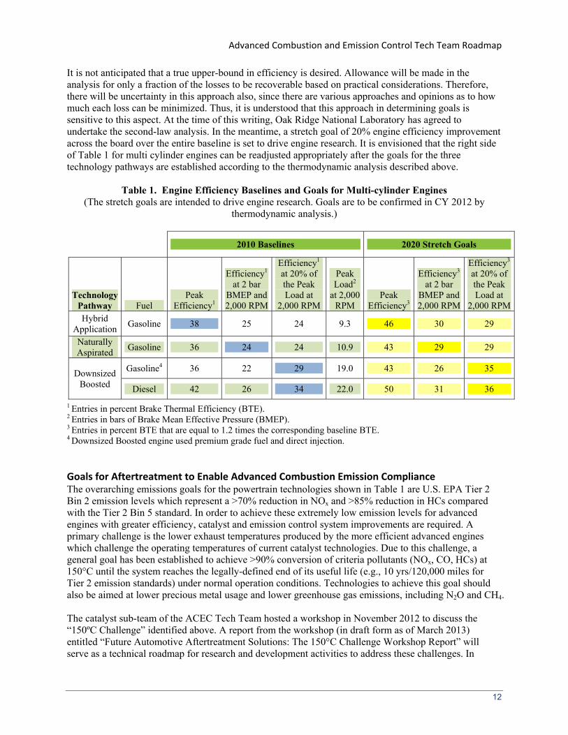
Advanced Combustion and Emission Control Tech Team Roadmap
Other mechanical exhaust energy recovery systems including Rankine Cycle systems are feasible However the packaging and cost of this system for a light-duty vehicle are not proven
Exhaust waste energy can be recovered electrically with a thermoelectric device Challenges for these devices are to identify materials with high efficiency in the temperature range of the exhaust Current material property changes with potential to increase efficiency include a ball-milling process to increase grain boundaries and skutterudites to improve thermal conductivity Other materials with better efficiency are required A thermoelectric system also consists of many thermal and electrical junctions Decreasing the contact resistance between junctions will improve efficiency Waste heat recovery from the exhaust of a light-duty vehicle is challenging since the urban drive cycle used for fuel-economy evaluation is a relatively load-load highly transient cycle and exhaust heat availability is limited
An alternate waste heat recovery strategy is to use a thermoelectric device to cool the passenger compartment This strategy has potential to remove the refrigerant which is a greenhouse gas and eliminate the mechanically driven HVAC compressor
Cross‐Cutting TechnologiesApproaches for Enabling Goals High-value cross-cutting technologies and approaches for helping enable the full emission compliant efficiency potential of engine technologies discussed in the prior sections include both hardware (eg sensors for monitoring and closed loop feedback Variable Valve Timing (VVT) and Variable Compression Ratio (VCR)) and thermodynamic analyses to identify promising directions for meeting targets Develop andor improve NOx and PM sensors for closed-loop control of engineaftertreatment system
and for determining aftertreatment breakthrough or poor performance Closed-loop control will provide the ability to optimize the engineaftertreatment system for performance and minimize aftertreatment fuel economy penalties Urea SCR systems will need an NH3 sensor insensitive to NOx
for optimizing operation ndash Real-time sensors and measurement tools for exhaust NOx and PM and for NH3 are lacking
Sensitive real-time PM measurement and sensor development are especially needed Moreover conventional oxygen sensors being used for air-fuel ratio monitoring have been found to have interference from hydrogen during fuel-rich LNT regeneration
Develop combustion sensors that can be used for feedback and control of combustion and for determining the combustion mode Such capabilities will be needed for fully implementing and controlling advanced combustion approaches especially mixed-mode engine operation and integration of engineaftertreatment systems ndash Combustion sensor technologies (eg pressure measurement) are under development but
improved durability and cost effectiveness are critical VVT and VCR technologies for enabling full utilization of LTC combustion strategies and for
maximizing engine efficiency ndash Highly flexible durable robust low-cost technologies are not ready for market implementation
Update the baseline energy and exergy distribution and loss data for modern diesel LTC lean burn DISI and hydrogen engines using models and experiments Understanding these data for various engine technologies is key to determining effective strategies for achieving higher efficiency ndash Baselines analysis of energy balances and availability (exergy) losses for modern engines are
inadequate Precompetitive data for such analyses especially for engines in LTC and stratified lean-burn gasoline modes is very limited
Develop and validate systematic strategies for mitigating the quantified losses using the resulting baseline energy and exergy data and track progress against strategies Place high priority on part load efficiency improvements since this is where more gain in over-the-road fuel economy can be achieved Specific examples include
25
Advanced Combustion and Emission Control Tech Team Roadmap
ndash Determine the extent that advanced combustion can be exploited to mitigate inherent exergy losses in combustion and heat transfer The inherent exergy losses in conventional combustion processes are among the largest losses in internal combustion engines
ndash Examine improvements to the base engine thermodynamic operation through greater expansion ratio recuperation reduced heat transfer combustion phasing downsizing and downspeeding Most strategies for efficiency improvement lack guidance from coupled energyexergy balance analyses Heat transfer and the impact on efficiency have been extensively addressed in ldquolow-heat rejection enginerdquo RampD but it remains a challenge
ndash Develop and validate new effective approaches to utilizing low-temperature energy from exhaust and EGR coolers Exhaust energy in high-efficiency engines especially diesel engines with coolers for EGR is of low-quality making effective heat recovery challenging
ndash Develop and validate novel approaches to reduce parasitic losses associated with accessories fueling systems and friction Friction reduction is a mature technology It has been the focus of substantial private sector research making further efficiency gains challenging Down speeding is one approach Diesel engine fuel injection has trended to higher injection pressure for emission controls This carries a notable parasitic loss especially at part load but also potential for optimization
ndash Improvements in boosting and exhaust energy utilization efficiency should be examined It is generally accepted that the efficiency of boosting systems affects overall engine efficiency Small turbochargers have inherent efficiency disadvantage
Powertrain Systems Integration for Enabling Goals Integration is the process of combining all the elements of the vehicle into a working system that meets customer requirements such as durability quality and performance and also meets regulatory requirements such as emissions safety and efficiency Complete vehicle systems integration is beyond the scope for the ACEC technical team This work is performed by each OEM during the design engineering and manufacture of a vehicle
The ACEC technical team can however address a subset of vehicle systems integration namely engine aftertreatment and fuel systems integration Effective integration of these systems with a focus on reducing the sizemass of components increasing robustness of the system over a wide range of inputs and discovering enablers such as sensors for control and diagnostics can further enable overall fuel economy emission compliance performance and durability requirements Some examples of ways in which we can improve the potential for integration of these systems into a vehicle are as follows Develop and validate robust mathematical models for each technology These models can be
combined in a total vehicle model during the OEM integration Use system level modeling for the engine transmission vehicle and fuel systems to identify the
optimal powertrain engine map and fuel characteristics for different vehicle scenario assumption This modeling gives direction to the technology development to ensure the result has potential for vehicle applications
Implementation of a technology requires sensors both for control and for diagnostics Suitable sensors and their control code should be developed as a part of a technology study Sensors are needed for combustion performance to detect specific species in the aftertreatment system and measure the fuel quality (as previously discussed)
Aftertreatment systems involve multiple catalyst devices (DOC LNT SCR DPF) If multiple aftertreatment functions can be performed by a single catalyst then fewer devices require packaging and integration improves
Catalysts in aftertreatment systems require specific temperatures for maximum efficiency Improvement in the catalyst conversion efficiency at lower temperatures improves potential for vehicle use
26
Advanced Combustion and Emission Control Tech Team Roadmap
Achievement of Tier 2 Bin 2 standards implies that aftertreatment systems must be capable of handling emissions immediately after engine startup for all varieties of combustion strategies In addition alternative fuel economy approaches employing hybrid powertrains that use intermittent engine operation will deprive downstream aftertreatment systems of heat Therefore in general engine strategies and aftertreatment technologies that reduce the catalyst light-off time and temperature (eg 150degC) and produce exhaust energy are important areas of research and development
Cost Strategy Discussions Cost assessments and strategies for engine technologies are a challenge for three reasons (1) The technologies content necessary to achieve the efficiency and emission objectives are not defined (2) Actual cost data is proprietary for each manufacturer and not publically disclosed And (3) the price of platinum group metals (PGMs) which are required for aftertreatment systems is extremely volatile which greatly complicates predicting future PGM-based catalyst costs
As stated previously the ACEC objectives are to achieve a 20 improvement in engine efficiency and Tier 2 Bin 2 emissions We propose three engine technology paths dilute gasoline clean diesel and low-temperature combustion Gasoline direct injection and clean diesel are in production but do not achieve the efficiency objective Only premixed stoichiometric spark-ignited combustion achieves the emission target Low-temperature combustion is not in production
Some public studies focused on fuel economyCO2 improvement estimate the cost of production ready technologies8 One publicly available cost study was done in 2008 by Martec They released a study of incremental costs relative to a gasoline PFI baseline for three technology paths relevant for the ACEC team projected to the 2013 to 2015 time frame The technologies included diesel stratified direct injection gasoline and turbocharged gasoline engines (LTC strategies were not covered) Martec assumed high-volume production accounted for current prices of materials such as precious metals and assumed Bin 5 emissions The incremental cost of the technology for 4 6 and 8 cylinder engines was estimated The cost of the base engine was not assessed The main results were as follows The largest incremental cost was for the diesel The smallest was for the turbocharged engine The largest contributors to the diesel engine incremental cost were boosting fuel injection and
aftertreatment systems The largest contributors to incremental cost were aftertreatment and fuel injection for the stratified direct injection engine and boosting for the turbocharged engine
Compared to the incremental cost of added technology for a turbocharged engine the incremental added-technology cost for the stratified direct injection engine was 12 to 17 times larger The incremental added-technology cost for the diesel engine was 3-4 times larger than that for the turbocharged engine The cost range corresponds to different content in the base engine and different assumed content depending on engine size
The cost changes from the Martec study were estimated at a point in time and with specified assumptions A manufacturer determines cost including development of the technologies to a production ready state calibration for vehicle operation and emissions integration in a vehicle and manufacturing tooling to the desired volume Manufacturer cost is proprietary and not disclosed publically
2017 and Later Model Year Light-Duty Vehicle Greenhouse Gas Emissions and Corporate Average Fuel Economy Standards EPA and NHTSA 2012 ldquoVariable Costs of Fuel Economy Technologiesrdquo Martec prepared for The Alliance of Automobile Manufacturers and public comment to NHTSA 2008 ldquoAssessment of Fuel Economy Technologies for Light-Duty Vehiclesrdquo National Academy of Science 2011 ldquoLight-Duty Vehicle Greenhouse Gas Emission Standards and Corporate Average Fuel Economy Standards Final Rulerdquo EPA and NHTSA Federal Register 2010
27
8
Advanced Combustion and Emission Control Tech Team Roadmap
Since the technology content to achieve the objectives is not defined and the costs cannot be quantified the ACEC technology development includes strategies that favor cost reduction The Martec study suggests some examples One is increase volume to reduce unit cost Unfortunately most added technologies cited for the systems considered are in high volume production and are in the second or later generation of production Some exceptions in their first generation are lean NOx aftertreatment for gasoline and diesel piezoelectric injectors for gasoline on-board diagnostics for diesel A second strategy is to eliminate or reduce content in one of the key components aftertreatment boosting and fuel injection Some examples cited previously in this document are Use LTC strategies with high efficiency to lower engine-out emissions and reduce aftertreatment
content and cost vs diesel Develop and improve efficiency of lean-burn DISI which has lower cost fuel injection components vs
diesel Develop new catalyst materials for NOx and PM reduction to improve the cost effectiveness of
aftertreatment systems vs todayrsquos lean systems Combine discrete aftertreatment elements into one component that accomplishes multiple
aftertreatment functions Focus on either naturally aspirated or slightly boosted engines to reduce the requirements for the
boosting device vs diesel or multiple stage turbocharged engine
A major element of the aftertreatment cost is the amount and price of PGMs PGM market volatility is greatly affected by mining and processing operations in foreign (and often less stable) countries Thus critical material supplies are subject to worldwide government stability and in general form a national point of economic concern Optimization of catalyst PGM is included in the research for different aftertreatment systems
In summary definition of detailed cost targets is a challenge for the ACEC Tech team due to the highly proprietary nature of costs for each OEM However cost minimization is clearly a critical goal Our team objective is to find commercially viable technology solutions that achieve the efficiency and emissions objectives
Research Leveraging with Other DOE Activities
Vehicle Technologies Office (VT) Significant leveraging of research in support of the ACEC Tech Team roadmap and goals occurs with other DOE VT activities These include the light-duty and heavy-duty truck projects propulsion materials activities and fuel technology subprogram The following are major areas of leveraging
Light Truck and Heavy Truck Diesel RampD Projects Light and heavy truck projects include substantial activity on engine technology combustion aftertreatment and related enabling technologies for the special requirements of these applications The potential cross-cutting application to passenger car vehicles is a key basis for creating the Advanced Engine Crosscut team that helps guide the research for maximum leveraged benefit The Advanced Engine Crosscut team includes the ACEC Tech team members and major truck engine OEMs Most of the effort in light- and heavy-duty truck programs is conducted via cooperative agreements with the engine OEMs or through CRADAs In addition the VT engine activities support health-effects studies of exhaust from diesel and spark-ignition engines of all size classes These health-effects efforts have resulted in an overall improvement in perspective concerning the health impacts of diesel engine exhaust
28
Advanced Combustion and Emission Control Tech Team Roadmap
Propulsion Materials Activity VTrsquos Propulsion Materials activity is addressing materials needs for catalytic aftertreatment systems sensors EGR components fuel systems and particle filter media that have direct application to emissions barriers for all engine technologies Furthermore the program supports materials RampD for lightweight valve trains low-inertia turbochargers and components for high bmep engines all being significant for higher efficiency Materials requirements for less friction yet adequate cylinder sealing are addressed as well
Fuels Technology Subprogram The Fuels Technology Subprogram conducts RampD in two significant thrusts (1) determine fuels characteristics that can help enable high-efficiency low-emission engine technologies and (2) conduct research that will stimulate or enable use of non-petroleum fuels emphasizing renewable fuels such as ethanol biodiesel and renewable diesel With respect to fuels as enablers the program has supported extensive studies of diesel fuel sulfur
effects on emission control devices and systems These efforts were cited in the EPA rules requiring low sulfur diesel fuel and have resulted in several complete test beds for fuel and emission control aging studies including a passenger car and a light-truck each equipped with NOx adsorber systems Methods are also being developed to study the fate of phosphorous compounds in aftertreatment systems
Research capabilities for determining the fundamental effects of fuel composition (including oxygenation) on combustion and emission processes in-cylinder have been developed and research is underway to determine fuel composition effects on diesel combustion and LTC regimes
Non-petroleum fuel options are also being examined as part of the program to determine their emissions characteristics and general compatibility with diesel and advanced combustion technologies
Research on how to tailor fuel composition to create optimal NOx catalyst reductants is underway Ethanol utilization research is focused on increasing E85 engine thermal efficiency (described in
previous sections of this report) and the feasibility of using up to E20 in certain segments of the legacy vehicle fleet
Office of Science Basic Energy Sciences (BES) Activities The BES activities provide the combustion and catalysis science underpinnings necessary for supporting the VT applied combustion and aftertreatment RampD activities
Gas-Phase Chemical Physics Activity Research on gas-phase combustion chemistry complex reacting flows and laser diagnostics for investigating complex reacting flows are critical research areas that are helping form a foundation for engine combustion research In addition the BES activities are developing high-fidelity modeling tools such as Direct Numerical Simulation and Large Eddy Simulation (LES) tools LES is now being directly leveraged by VT VT activities are funding efforts to extend and apply LES in close coordination with critical engine combustion experiments to provide new understanding about advanced engine combustion strategies not obtainable through experiments alone Moreover the high-fidelity computational tools being developed and applied will help improve engineering CFD tools such as KIVA and will lead to a new generation of engine simulation tools required for simulating stochastic challenges that face engine designers (eg misfire for stratified charge DISI engines and low-speed preignition for downsized boosted engines) Recently BES and VT jointly funded a Combustion Research and Computational Visualization facility at the Combustion Research Facility for jointly developing and applying the new high-fidelity simulation tools in close coordination with fundamental and applied experimental combustion research
29
Advanced Combustion and Emission Control Tech Team Roadmap
Catalysis Science Activity This program office within BES funds the largest fraction of basic research in catalysis in the Federal government and produces research outcomes of relevance to programs of the Office of Energy Efficiency and Renewable Energy including the VT programs and of the Office of Fossil Energy This activity develops the fundamental scientific principles enabling rational catalyst design and chemical transformation control Research includes the identification of the elementary steps of catalytic reaction mechanisms and their kinetics and the construction and determination of active catalytic sites at the atomic level The Advanced Combustion and Emission Control activities are leveraged with the BESCatalysis Science (BESCS) program in two important ways First recent BESCS funded studies have identified novel catalyst materials and structures that provide for significantly lower temperature reactivity For example the BESCS program has funded several studies of new supported gold catalysts which display excellent activity for the CO oxidation reaction even at room temperature A considerable number of their currently funded efforts are devoted to determining the specific chemical and physical nature of these supported gold catalysts as well as how these unique properties can be maintained under more harsh and realistic conditions Secondly the BESCS program continues to invest considerable resources aimed at the development of theory modeling and simulation of catalyst materials and catalytic pathways These developments are directly applicable to the VT-funded Cross-Cut Lean Exhaust Emissions Reduction Simulations (CLEERS) activity
30
Advanced Combustion and Emission Control Tech Team Roadmap
Appendix A Hydrogen‐Fueled Engines The ACEC Technical Team has been considering hydrogen as a fuel for enabling high-efficiency clean engines Hydrogen has a high flame speed very lean ignitability limits and contains no carbon giving it the potential for diesel-engine like efficiencies conventional spark-ignition control of combustion timing and very low engine-out emissions including CO2 emissions9 Hydrogen ICEs offer a bridging opportunity to hydrogen fuel-cells If these engines were mass-marketed in the near-term they could stimulate the hydrogen infrastructure storage dispensing and safety technologies thus promoting the longer term US DRIVE goal of transitioning to a hydrogen economy
Significant progress has been made on hydrogen-fuelled ICEs While technical barriers remain the potential for direct-injection hydrogen ICEs with 45 brake thermal efficiency and low emissions was demonstrated in the lab This fuel efficiency potential is close to that of fuel cells However due to changes in research funding priorities the lack of an emerging hydrogen fueling infrastructure research on hydrogen-fueled ICEs has been tabled The following discussion in this appendix documents the current state of hydrogen ICE technology and the remaining barriers requiring research should research on this technology direction be reestablished
The Current Baseline Production Powertrain Technology
Hydrogen‐fueled SI Engines The Hydrogen-fueled Internal Combustion Engine (H2ICE) efforts have been focused on utilizing the unique combustion characteristics of hydrogen to achieve an advanced SI-based engine that has a high efficiency (comparable to a diesel engine) performance characteristics comparable to a conventional PFI gasoline engine and emissions that are effectively zero The unique combustion characteristics of hydrogen include a very low lower-flammability limit and a high flame speed These characteristics allow very dilute (ie very low-temperature) stable SI combustion with drastically reduced NOx production High dilution also enables efficient part-load operation (ie operation without the throttling losses of conventional PFI engines) Engine-out hydrocarbon CO and CO2 emissions are also limited to trace amounts resulting from lubricating oil Design advancements such as higher boost pressure and downsizing offer even higher efficiencies and power densities possibly exceeding those of hydrocarbonshyfuelled engines The current state of hydrogen-fueled IC engine technology can be summarized as follows A number of test demonstration and commercial PFI H2ICE vehicles using premixed SI engine
technology have been built by Ford BMW Mazda Quantum and others Recent examples that include light-duty and some heavy-duty engines all in very small quantities include the BMW Hydrogen 7 demonstration vehicle (~100 vehicles) with emissions well below SULEV standards QuantumFord Escape and Prius H2ICE hybrid vehicles and a Silverado H2ICE conversion by Electric Transportation Energy Corporation and the commercially sold Ford E-450 shuttle bus (30 vehicles) with premixed supercharged hydrogen SI engine technology meeting Phase II heavy-duty 2010 emission standards with over 997 reduction of CO CO and NMHC In Japan Mazda is also leasing RX8 vehicles with rotary gasolineH2 and mono H2 fueling In Europe H2ICE activity includes MAN with the HyFleet Cute Program described at httpwwwglobal-hydrogen-busshyplatformcomTechnologyHydrogenInternalCombustionEngines)
Gen-sets powered by hydrogen-fueled engines are commercially available in low volume (Hydrogen Engine Company others)
While tail-pipe CO2 emissions may be zero CO2 emissions incurred by the generation of hydrogen must be considered
A-1
9
Advanced Combustion and Emission Control Tech Team Roadmap
Premixed H2ICE technology operating under lean conditions with intake air pressure boosting to produce power densities approaching conventional gasoline PFI technology have been demonstrated under research conditions with peak brake thermal efficiencies of over 40 by Ford with emissions below SULEV
Turbo-charged direct-injection (DI) H2ICE technology with power density greater than a comparable naturally aspirated gasoline engine has been demonstrated in the lab with peak brake thermal efficiencies of 455 (based on single-cylinder research engine data) Vehicle level simulations based on these results suggest a potential for meeting 2016 CAFE targets and Tier 2 Bin 2 (SULEV) emissions without aftertreatment Further fuel economy improvement potential through engine downsizing is also a possibility
Costs for H2 engines are comparable to conventional gasoline fueled SI engine10
When hybridized advanced H2ICE powertrains are projected to offer driving cycle efficiency comparable to advanced fuel cell vehicles with acceptable performance and all weather capability Current Hybrid H2ICEs in demonstration fleets have shown similar fuel economy to current fuel cells (South Coast Air Quality Management District fleet usage reports)
BarriersTechnical Strategies
Hydrogen‐fueled SI Engines The primary path to high efficiency use of hydrogen in ICEs is direct-injection (DI) spark-ignited (SI) H2ICEs DI-H2ICE offers the potential for fuel efficiency approaching or exceeding that of current high-efficiency diesel engines power densities comparable to or greater than conventional PFI gasoline engines and emissions compliant with EPA Tier 2 Bin 2 all in a cost effective durable manner DIshyH2ICE also has the potential to largely overcome the pre-ignition and flashback challenges for PFI-type H2ICEs Major barriers related to DI-H2ICE engines include (a) developing a robust durable cost-effective DI hydrogen combustion system including hydrogen fuel injectors and boosting technologies and (b) hydrogen compatible emission control technologies that are also robust and cost effective
Specific technical strategies with associated barrier discussion are as follows
Combustion Technology Develop the fundamental knowledge-base and simulation tools for DI-H2ICE SI combustion
and NOx emission processes This includes ultra-lean (for idle) to stoichiometric conditions and use of boosted high EGR at stoichiometric conditions as a potential NOx control strategy including both premixed and stratified conditions
ndash The knowledge-base for supporting the development of DI-H2ICEs and the simulation tools for designing and optimizing them is limited The required lean or dilute high-pressure and high-temperature in-cylinder conditions push combustion into a parameter space where hydrogen combustion stability combustion duration and pre-ignition phenomena are not well understood Improved understanding of hydrogen SI combustion progress and stability pre-ignition phenomena and NOx emission formation over the expected range engine speeds and loads combustion chamber geometries and in-cylinder air motions (eg swirl) is required
Improve the understanding of DI hydrogen injection and hydrogen-air mixing processes and models for simulation ndash DI offers the highest engine power density as well as reduced pre-ignition problems and
improved safety by eliminating the possibility for flashback By timing the direct injection after
10 It should be noted that the same as for fuel cells commercially viable on-board hydrogen storage and hydrogen production distribution and fueling infrastructure must be developed and add to vehicle cost
A-2
Advanced Combustion and Emission Control Tech Team Roadmap
intake-valve closure 20-30 improvement in power density can be achieved relative to injection before intake-valve closure However a lean or dilute and nearly homogeneous mixture must be created by the hydrogen jet and in-cylinder gas motion before spark ignition and combustion of mixtures rich enough to form significant NOx occurs
Aggressive use of EGR (levels up to 50) and boosting to achieve dilute stoichiometric combustion at high-loads coupled with low-NOx lean combustion at light to moderate loads has potential as an H2ICE strategy Another strategy is stoichiometric combustion coupled with a more conventional TWC for high loads and low-NOx lean combustion at light to moderate loads ndash The load range capabilities for these options are unknown and must be determined
Develop hydrogen compatible technologies for high-power-density high-efficiency SI H2ICE eg turbosuper-chargers intercoolers high compression ratios high EGR delivery components hydrogen injectors for DI operation pistons and rings spark-plugs and lubricant technology ndash Commercially viable DI hydrogen injectors do not exist Reliability durability and lubrication
(hydrogen has no lubricity) are significant challenges Additionally the high diffusivity and small molecular size of hydrogen makes injector leakage an issue Electronic actuationcontrol will be essential for integration into modern engine control systems
ndash Compatibility with hydrogen and effectiveness for DI H2ICE conditions are largely unknown Hydrogen embrittles many materials
ndash Components to deliver high EGR levels without throttling do not exist ndash Lubricants will be the only source of hydrocarbon emissions additionally very effective
lubricant control is needed to minimize deposits in the combustion chamber that can lead to preignition problems and deposits on valve heads that can affect breathing performance and emissions
Aftertreatment Technology for Hydrogen Engines The primary pollutant from H2ICEs is NOx if undiluted fuel-air mixture equivalence ratios from about 06 to stoichiometric are present in the combustion strategy Envisioned strategies try to avoid equivalence ratios in the 06 to 10 range If stoichiometric combustion is used to achieve high loads a conventional-type TWC is currently the envisioned aftertreatment technology If combustion in the 06 to close to stoichiometric range is required lean combustion aftertreatment like the LNT may be required
Determine optimal TWC catalyst composition requirements for operation with stoichiometric hydrogen combustion exhaust streams ndash Integration of TWC with stoichiometric hydrogen for optimal low cost performance has not been
done If EGR-dilution is not used lean SI combustion in approximately the 06 to 10 range is required for
an effective combustion system other lean burn NOx technologies must be pursued eg SCRs LNTs hybrid LNT and SCR systems ndash The performance of these technologies in a hydrogen-fueled ICE system is not understood and
development for the application is required Compatibility with hydrogen is unknown Development associated with other engine technologies must be extended to include hydrogen ICE conditions to achieve optimal cost effective operation An example is determining LNT performance with H2 as the reductant during regeneration and optimal LNT catalyst formulations Another would be exploring a hybrid LNTSCR system using rich hydrogen exhaust gas to generate NH3 for the SCR
A-3
- Cover
- Table of Contents
- Introduction
-
- Low‐Temperature Combustion (LTC)
- Dilute Gasoline Combustion
- Clean Diesel Combustion
- Fuels Utilization
-
- The Current Baseline Production Powertrain Technology
- Fuel Economy and Emission Regulations and Trends
-
- Fuel Economy
- Emissions
-
- State of Advanced Powertrain Technologies
-
- Low‐Temperature Combustion
- Dilute Gasoline Combustion
- Clean Diesel Combustion
- Parasitic Loss Reduction and Waste Heat Recovery
-
- Goals
-
- Technological Pathways to Increases in Engine Efficiency
- Engine Speeds and Loads for Efficiency Testing and Reporting
- Baseline Engine Efficiencies
- Goals for Engine Efficiency Increases
- Goals for Aftertreatment to Enable Advanced Combustion Emission Compliance
-
- BarriersTechnical Strategies
-
- Low‐Temperature Combustion
- Dilute Gasoline Combustion
- Clean Diesel Combustion
- Parasitic Loss Reduction and Waste Heat Recovery
- Cross‐Cutting TechnologiesApproaches for Enabling Goals
- Powertrain Systems Integration for Enabling Goals
-
- Cost Strategy Discussions
- Research Leveraging with Other DOE Activities
-
- Vehicle Technologies Office (VT)
- Office of Science Basic Energy Sciences (BES) Activities
-
- Appendix A Hydrogen‐Fueled Engines
-
- The Current Baseline Production Powertrain Technology
-
- Hydrogen‐fueled SI Engines
-
- BarriersTechnical Strategies
-
- Hydrogen‐fueled SI Engines
-
Advanced Combustion and Emission Control Tech Team Roadmap
ndash Determine the extent that advanced combustion can be exploited to mitigate inherent exergy losses in combustion and heat transfer The inherent exergy losses in conventional combustion processes are among the largest losses in internal combustion engines
ndash Examine improvements to the base engine thermodynamic operation through greater expansion ratio recuperation reduced heat transfer combustion phasing downsizing and downspeeding Most strategies for efficiency improvement lack guidance from coupled energyexergy balance analyses Heat transfer and the impact on efficiency have been extensively addressed in ldquolow-heat rejection enginerdquo RampD but it remains a challenge
ndash Develop and validate new effective approaches to utilizing low-temperature energy from exhaust and EGR coolers Exhaust energy in high-efficiency engines especially diesel engines with coolers for EGR is of low-quality making effective heat recovery challenging
ndash Develop and validate novel approaches to reduce parasitic losses associated with accessories fueling systems and friction Friction reduction is a mature technology It has been the focus of substantial private sector research making further efficiency gains challenging Down speeding is one approach Diesel engine fuel injection has trended to higher injection pressure for emission controls This carries a notable parasitic loss especially at part load but also potential for optimization
ndash Improvements in boosting and exhaust energy utilization efficiency should be examined It is generally accepted that the efficiency of boosting systems affects overall engine efficiency Small turbochargers have inherent efficiency disadvantage
Powertrain Systems Integration for Enabling Goals Integration is the process of combining all the elements of the vehicle into a working system that meets customer requirements such as durability quality and performance and also meets regulatory requirements such as emissions safety and efficiency Complete vehicle systems integration is beyond the scope for the ACEC technical team This work is performed by each OEM during the design engineering and manufacture of a vehicle
The ACEC technical team can however address a subset of vehicle systems integration namely engine aftertreatment and fuel systems integration Effective integration of these systems with a focus on reducing the sizemass of components increasing robustness of the system over a wide range of inputs and discovering enablers such as sensors for control and diagnostics can further enable overall fuel economy emission compliance performance and durability requirements Some examples of ways in which we can improve the potential for integration of these systems into a vehicle are as follows Develop and validate robust mathematical models for each technology These models can be
combined in a total vehicle model during the OEM integration Use system level modeling for the engine transmission vehicle and fuel systems to identify the
optimal powertrain engine map and fuel characteristics for different vehicle scenario assumption This modeling gives direction to the technology development to ensure the result has potential for vehicle applications
Implementation of a technology requires sensors both for control and for diagnostics Suitable sensors and their control code should be developed as a part of a technology study Sensors are needed for combustion performance to detect specific species in the aftertreatment system and measure the fuel quality (as previously discussed)
Aftertreatment systems involve multiple catalyst devices (DOC LNT SCR DPF) If multiple aftertreatment functions can be performed by a single catalyst then fewer devices require packaging and integration improves
Catalysts in aftertreatment systems require specific temperatures for maximum efficiency Improvement in the catalyst conversion efficiency at lower temperatures improves potential for vehicle use
26
Advanced Combustion and Emission Control Tech Team Roadmap
Achievement of Tier 2 Bin 2 standards implies that aftertreatment systems must be capable of handling emissions immediately after engine startup for all varieties of combustion strategies In addition alternative fuel economy approaches employing hybrid powertrains that use intermittent engine operation will deprive downstream aftertreatment systems of heat Therefore in general engine strategies and aftertreatment technologies that reduce the catalyst light-off time and temperature (eg 150degC) and produce exhaust energy are important areas of research and development
Cost Strategy Discussions Cost assessments and strategies for engine technologies are a challenge for three reasons (1) The technologies content necessary to achieve the efficiency and emission objectives are not defined (2) Actual cost data is proprietary for each manufacturer and not publically disclosed And (3) the price of platinum group metals (PGMs) which are required for aftertreatment systems is extremely volatile which greatly complicates predicting future PGM-based catalyst costs
As stated previously the ACEC objectives are to achieve a 20 improvement in engine efficiency and Tier 2 Bin 2 emissions We propose three engine technology paths dilute gasoline clean diesel and low-temperature combustion Gasoline direct injection and clean diesel are in production but do not achieve the efficiency objective Only premixed stoichiometric spark-ignited combustion achieves the emission target Low-temperature combustion is not in production
Some public studies focused on fuel economyCO2 improvement estimate the cost of production ready technologies8 One publicly available cost study was done in 2008 by Martec They released a study of incremental costs relative to a gasoline PFI baseline for three technology paths relevant for the ACEC team projected to the 2013 to 2015 time frame The technologies included diesel stratified direct injection gasoline and turbocharged gasoline engines (LTC strategies were not covered) Martec assumed high-volume production accounted for current prices of materials such as precious metals and assumed Bin 5 emissions The incremental cost of the technology for 4 6 and 8 cylinder engines was estimated The cost of the base engine was not assessed The main results were as follows The largest incremental cost was for the diesel The smallest was for the turbocharged engine The largest contributors to the diesel engine incremental cost were boosting fuel injection and
aftertreatment systems The largest contributors to incremental cost were aftertreatment and fuel injection for the stratified direct injection engine and boosting for the turbocharged engine
Compared to the incremental cost of added technology for a turbocharged engine the incremental added-technology cost for the stratified direct injection engine was 12 to 17 times larger The incremental added-technology cost for the diesel engine was 3-4 times larger than that for the turbocharged engine The cost range corresponds to different content in the base engine and different assumed content depending on engine size
The cost changes from the Martec study were estimated at a point in time and with specified assumptions A manufacturer determines cost including development of the technologies to a production ready state calibration for vehicle operation and emissions integration in a vehicle and manufacturing tooling to the desired volume Manufacturer cost is proprietary and not disclosed publically
2017 and Later Model Year Light-Duty Vehicle Greenhouse Gas Emissions and Corporate Average Fuel Economy Standards EPA and NHTSA 2012 ldquoVariable Costs of Fuel Economy Technologiesrdquo Martec prepared for The Alliance of Automobile Manufacturers and public comment to NHTSA 2008 ldquoAssessment of Fuel Economy Technologies for Light-Duty Vehiclesrdquo National Academy of Science 2011 ldquoLight-Duty Vehicle Greenhouse Gas Emission Standards and Corporate Average Fuel Economy Standards Final Rulerdquo EPA and NHTSA Federal Register 2010
27
8
Advanced Combustion and Emission Control Tech Team Roadmap
Since the technology content to achieve the objectives is not defined and the costs cannot be quantified the ACEC technology development includes strategies that favor cost reduction The Martec study suggests some examples One is increase volume to reduce unit cost Unfortunately most added technologies cited for the systems considered are in high volume production and are in the second or later generation of production Some exceptions in their first generation are lean NOx aftertreatment for gasoline and diesel piezoelectric injectors for gasoline on-board diagnostics for diesel A second strategy is to eliminate or reduce content in one of the key components aftertreatment boosting and fuel injection Some examples cited previously in this document are Use LTC strategies with high efficiency to lower engine-out emissions and reduce aftertreatment
content and cost vs diesel Develop and improve efficiency of lean-burn DISI which has lower cost fuel injection components vs
diesel Develop new catalyst materials for NOx and PM reduction to improve the cost effectiveness of
aftertreatment systems vs todayrsquos lean systems Combine discrete aftertreatment elements into one component that accomplishes multiple
aftertreatment functions Focus on either naturally aspirated or slightly boosted engines to reduce the requirements for the
boosting device vs diesel or multiple stage turbocharged engine
A major element of the aftertreatment cost is the amount and price of PGMs PGM market volatility is greatly affected by mining and processing operations in foreign (and often less stable) countries Thus critical material supplies are subject to worldwide government stability and in general form a national point of economic concern Optimization of catalyst PGM is included in the research for different aftertreatment systems
In summary definition of detailed cost targets is a challenge for the ACEC Tech team due to the highly proprietary nature of costs for each OEM However cost minimization is clearly a critical goal Our team objective is to find commercially viable technology solutions that achieve the efficiency and emissions objectives
Research Leveraging with Other DOE Activities
Vehicle Technologies Office (VT) Significant leveraging of research in support of the ACEC Tech Team roadmap and goals occurs with other DOE VT activities These include the light-duty and heavy-duty truck projects propulsion materials activities and fuel technology subprogram The following are major areas of leveraging
Light Truck and Heavy Truck Diesel RampD Projects Light and heavy truck projects include substantial activity on engine technology combustion aftertreatment and related enabling technologies for the special requirements of these applications The potential cross-cutting application to passenger car vehicles is a key basis for creating the Advanced Engine Crosscut team that helps guide the research for maximum leveraged benefit The Advanced Engine Crosscut team includes the ACEC Tech team members and major truck engine OEMs Most of the effort in light- and heavy-duty truck programs is conducted via cooperative agreements with the engine OEMs or through CRADAs In addition the VT engine activities support health-effects studies of exhaust from diesel and spark-ignition engines of all size classes These health-effects efforts have resulted in an overall improvement in perspective concerning the health impacts of diesel engine exhaust
28
Advanced Combustion and Emission Control Tech Team Roadmap
Propulsion Materials Activity VTrsquos Propulsion Materials activity is addressing materials needs for catalytic aftertreatment systems sensors EGR components fuel systems and particle filter media that have direct application to emissions barriers for all engine technologies Furthermore the program supports materials RampD for lightweight valve trains low-inertia turbochargers and components for high bmep engines all being significant for higher efficiency Materials requirements for less friction yet adequate cylinder sealing are addressed as well
Fuels Technology Subprogram The Fuels Technology Subprogram conducts RampD in two significant thrusts (1) determine fuels characteristics that can help enable high-efficiency low-emission engine technologies and (2) conduct research that will stimulate or enable use of non-petroleum fuels emphasizing renewable fuels such as ethanol biodiesel and renewable diesel With respect to fuels as enablers the program has supported extensive studies of diesel fuel sulfur
effects on emission control devices and systems These efforts were cited in the EPA rules requiring low sulfur diesel fuel and have resulted in several complete test beds for fuel and emission control aging studies including a passenger car and a light-truck each equipped with NOx adsorber systems Methods are also being developed to study the fate of phosphorous compounds in aftertreatment systems
Research capabilities for determining the fundamental effects of fuel composition (including oxygenation) on combustion and emission processes in-cylinder have been developed and research is underway to determine fuel composition effects on diesel combustion and LTC regimes
Non-petroleum fuel options are also being examined as part of the program to determine their emissions characteristics and general compatibility with diesel and advanced combustion technologies
Research on how to tailor fuel composition to create optimal NOx catalyst reductants is underway Ethanol utilization research is focused on increasing E85 engine thermal efficiency (described in
previous sections of this report) and the feasibility of using up to E20 in certain segments of the legacy vehicle fleet
Office of Science Basic Energy Sciences (BES) Activities The BES activities provide the combustion and catalysis science underpinnings necessary for supporting the VT applied combustion and aftertreatment RampD activities
Gas-Phase Chemical Physics Activity Research on gas-phase combustion chemistry complex reacting flows and laser diagnostics for investigating complex reacting flows are critical research areas that are helping form a foundation for engine combustion research In addition the BES activities are developing high-fidelity modeling tools such as Direct Numerical Simulation and Large Eddy Simulation (LES) tools LES is now being directly leveraged by VT VT activities are funding efforts to extend and apply LES in close coordination with critical engine combustion experiments to provide new understanding about advanced engine combustion strategies not obtainable through experiments alone Moreover the high-fidelity computational tools being developed and applied will help improve engineering CFD tools such as KIVA and will lead to a new generation of engine simulation tools required for simulating stochastic challenges that face engine designers (eg misfire for stratified charge DISI engines and low-speed preignition for downsized boosted engines) Recently BES and VT jointly funded a Combustion Research and Computational Visualization facility at the Combustion Research Facility for jointly developing and applying the new high-fidelity simulation tools in close coordination with fundamental and applied experimental combustion research
29
Advanced Combustion and Emission Control Tech Team Roadmap
Catalysis Science Activity This program office within BES funds the largest fraction of basic research in catalysis in the Federal government and produces research outcomes of relevance to programs of the Office of Energy Efficiency and Renewable Energy including the VT programs and of the Office of Fossil Energy This activity develops the fundamental scientific principles enabling rational catalyst design and chemical transformation control Research includes the identification of the elementary steps of catalytic reaction mechanisms and their kinetics and the construction and determination of active catalytic sites at the atomic level The Advanced Combustion and Emission Control activities are leveraged with the BESCatalysis Science (BESCS) program in two important ways First recent BESCS funded studies have identified novel catalyst materials and structures that provide for significantly lower temperature reactivity For example the BESCS program has funded several studies of new supported gold catalysts which display excellent activity for the CO oxidation reaction even at room temperature A considerable number of their currently funded efforts are devoted to determining the specific chemical and physical nature of these supported gold catalysts as well as how these unique properties can be maintained under more harsh and realistic conditions Secondly the BESCS program continues to invest considerable resources aimed at the development of theory modeling and simulation of catalyst materials and catalytic pathways These developments are directly applicable to the VT-funded Cross-Cut Lean Exhaust Emissions Reduction Simulations (CLEERS) activity
30
Advanced Combustion and Emission Control Tech Team Roadmap
Appendix A Hydrogen‐Fueled Engines The ACEC Technical Team has been considering hydrogen as a fuel for enabling high-efficiency clean engines Hydrogen has a high flame speed very lean ignitability limits and contains no carbon giving it the potential for diesel-engine like efficiencies conventional spark-ignition control of combustion timing and very low engine-out emissions including CO2 emissions9 Hydrogen ICEs offer a bridging opportunity to hydrogen fuel-cells If these engines were mass-marketed in the near-term they could stimulate the hydrogen infrastructure storage dispensing and safety technologies thus promoting the longer term US DRIVE goal of transitioning to a hydrogen economy
Significant progress has been made on hydrogen-fuelled ICEs While technical barriers remain the potential for direct-injection hydrogen ICEs with 45 brake thermal efficiency and low emissions was demonstrated in the lab This fuel efficiency potential is close to that of fuel cells However due to changes in research funding priorities the lack of an emerging hydrogen fueling infrastructure research on hydrogen-fueled ICEs has been tabled The following discussion in this appendix documents the current state of hydrogen ICE technology and the remaining barriers requiring research should research on this technology direction be reestablished
The Current Baseline Production Powertrain Technology
Hydrogen‐fueled SI Engines The Hydrogen-fueled Internal Combustion Engine (H2ICE) efforts have been focused on utilizing the unique combustion characteristics of hydrogen to achieve an advanced SI-based engine that has a high efficiency (comparable to a diesel engine) performance characteristics comparable to a conventional PFI gasoline engine and emissions that are effectively zero The unique combustion characteristics of hydrogen include a very low lower-flammability limit and a high flame speed These characteristics allow very dilute (ie very low-temperature) stable SI combustion with drastically reduced NOx production High dilution also enables efficient part-load operation (ie operation without the throttling losses of conventional PFI engines) Engine-out hydrocarbon CO and CO2 emissions are also limited to trace amounts resulting from lubricating oil Design advancements such as higher boost pressure and downsizing offer even higher efficiencies and power densities possibly exceeding those of hydrocarbonshyfuelled engines The current state of hydrogen-fueled IC engine technology can be summarized as follows A number of test demonstration and commercial PFI H2ICE vehicles using premixed SI engine
technology have been built by Ford BMW Mazda Quantum and others Recent examples that include light-duty and some heavy-duty engines all in very small quantities include the BMW Hydrogen 7 demonstration vehicle (~100 vehicles) with emissions well below SULEV standards QuantumFord Escape and Prius H2ICE hybrid vehicles and a Silverado H2ICE conversion by Electric Transportation Energy Corporation and the commercially sold Ford E-450 shuttle bus (30 vehicles) with premixed supercharged hydrogen SI engine technology meeting Phase II heavy-duty 2010 emission standards with over 997 reduction of CO CO and NMHC In Japan Mazda is also leasing RX8 vehicles with rotary gasolineH2 and mono H2 fueling In Europe H2ICE activity includes MAN with the HyFleet Cute Program described at httpwwwglobal-hydrogen-busshyplatformcomTechnologyHydrogenInternalCombustionEngines)
Gen-sets powered by hydrogen-fueled engines are commercially available in low volume (Hydrogen Engine Company others)
While tail-pipe CO2 emissions may be zero CO2 emissions incurred by the generation of hydrogen must be considered
A-1
9
Advanced Combustion and Emission Control Tech Team Roadmap
Premixed H2ICE technology operating under lean conditions with intake air pressure boosting to produce power densities approaching conventional gasoline PFI technology have been demonstrated under research conditions with peak brake thermal efficiencies of over 40 by Ford with emissions below SULEV
Turbo-charged direct-injection (DI) H2ICE technology with power density greater than a comparable naturally aspirated gasoline engine has been demonstrated in the lab with peak brake thermal efficiencies of 455 (based on single-cylinder research engine data) Vehicle level simulations based on these results suggest a potential for meeting 2016 CAFE targets and Tier 2 Bin 2 (SULEV) emissions without aftertreatment Further fuel economy improvement potential through engine downsizing is also a possibility
Costs for H2 engines are comparable to conventional gasoline fueled SI engine10
When hybridized advanced H2ICE powertrains are projected to offer driving cycle efficiency comparable to advanced fuel cell vehicles with acceptable performance and all weather capability Current Hybrid H2ICEs in demonstration fleets have shown similar fuel economy to current fuel cells (South Coast Air Quality Management District fleet usage reports)
BarriersTechnical Strategies
Hydrogen‐fueled SI Engines The primary path to high efficiency use of hydrogen in ICEs is direct-injection (DI) spark-ignited (SI) H2ICEs DI-H2ICE offers the potential for fuel efficiency approaching or exceeding that of current high-efficiency diesel engines power densities comparable to or greater than conventional PFI gasoline engines and emissions compliant with EPA Tier 2 Bin 2 all in a cost effective durable manner DIshyH2ICE also has the potential to largely overcome the pre-ignition and flashback challenges for PFI-type H2ICEs Major barriers related to DI-H2ICE engines include (a) developing a robust durable cost-effective DI hydrogen combustion system including hydrogen fuel injectors and boosting technologies and (b) hydrogen compatible emission control technologies that are also robust and cost effective
Specific technical strategies with associated barrier discussion are as follows
Combustion Technology Develop the fundamental knowledge-base and simulation tools for DI-H2ICE SI combustion
and NOx emission processes This includes ultra-lean (for idle) to stoichiometric conditions and use of boosted high EGR at stoichiometric conditions as a potential NOx control strategy including both premixed and stratified conditions
ndash The knowledge-base for supporting the development of DI-H2ICEs and the simulation tools for designing and optimizing them is limited The required lean or dilute high-pressure and high-temperature in-cylinder conditions push combustion into a parameter space where hydrogen combustion stability combustion duration and pre-ignition phenomena are not well understood Improved understanding of hydrogen SI combustion progress and stability pre-ignition phenomena and NOx emission formation over the expected range engine speeds and loads combustion chamber geometries and in-cylinder air motions (eg swirl) is required
Improve the understanding of DI hydrogen injection and hydrogen-air mixing processes and models for simulation ndash DI offers the highest engine power density as well as reduced pre-ignition problems and
improved safety by eliminating the possibility for flashback By timing the direct injection after
10 It should be noted that the same as for fuel cells commercially viable on-board hydrogen storage and hydrogen production distribution and fueling infrastructure must be developed and add to vehicle cost
A-2
Advanced Combustion and Emission Control Tech Team Roadmap
intake-valve closure 20-30 improvement in power density can be achieved relative to injection before intake-valve closure However a lean or dilute and nearly homogeneous mixture must be created by the hydrogen jet and in-cylinder gas motion before spark ignition and combustion of mixtures rich enough to form significant NOx occurs
Aggressive use of EGR (levels up to 50) and boosting to achieve dilute stoichiometric combustion at high-loads coupled with low-NOx lean combustion at light to moderate loads has potential as an H2ICE strategy Another strategy is stoichiometric combustion coupled with a more conventional TWC for high loads and low-NOx lean combustion at light to moderate loads ndash The load range capabilities for these options are unknown and must be determined
Develop hydrogen compatible technologies for high-power-density high-efficiency SI H2ICE eg turbosuper-chargers intercoolers high compression ratios high EGR delivery components hydrogen injectors for DI operation pistons and rings spark-plugs and lubricant technology ndash Commercially viable DI hydrogen injectors do not exist Reliability durability and lubrication
(hydrogen has no lubricity) are significant challenges Additionally the high diffusivity and small molecular size of hydrogen makes injector leakage an issue Electronic actuationcontrol will be essential for integration into modern engine control systems
ndash Compatibility with hydrogen and effectiveness for DI H2ICE conditions are largely unknown Hydrogen embrittles many materials
ndash Components to deliver high EGR levels without throttling do not exist ndash Lubricants will be the only source of hydrocarbon emissions additionally very effective
lubricant control is needed to minimize deposits in the combustion chamber that can lead to preignition problems and deposits on valve heads that can affect breathing performance and emissions
Aftertreatment Technology for Hydrogen Engines The primary pollutant from H2ICEs is NOx if undiluted fuel-air mixture equivalence ratios from about 06 to stoichiometric are present in the combustion strategy Envisioned strategies try to avoid equivalence ratios in the 06 to 10 range If stoichiometric combustion is used to achieve high loads a conventional-type TWC is currently the envisioned aftertreatment technology If combustion in the 06 to close to stoichiometric range is required lean combustion aftertreatment like the LNT may be required
Determine optimal TWC catalyst composition requirements for operation with stoichiometric hydrogen combustion exhaust streams ndash Integration of TWC with stoichiometric hydrogen for optimal low cost performance has not been
done If EGR-dilution is not used lean SI combustion in approximately the 06 to 10 range is required for
an effective combustion system other lean burn NOx technologies must be pursued eg SCRs LNTs hybrid LNT and SCR systems ndash The performance of these technologies in a hydrogen-fueled ICE system is not understood and
development for the application is required Compatibility with hydrogen is unknown Development associated with other engine technologies must be extended to include hydrogen ICE conditions to achieve optimal cost effective operation An example is determining LNT performance with H2 as the reductant during regeneration and optimal LNT catalyst formulations Another would be exploring a hybrid LNTSCR system using rich hydrogen exhaust gas to generate NH3 for the SCR
A-3
- Cover
- Table of Contents
- Introduction
-
- Low‐Temperature Combustion (LTC)
- Dilute Gasoline Combustion
- Clean Diesel Combustion
- Fuels Utilization
-
- The Current Baseline Production Powertrain Technology
- Fuel Economy and Emission Regulations and Trends
-
- Fuel Economy
- Emissions
-
- State of Advanced Powertrain Technologies
-
- Low‐Temperature Combustion
- Dilute Gasoline Combustion
- Clean Diesel Combustion
- Parasitic Loss Reduction and Waste Heat Recovery
-
- Goals
-
- Technological Pathways to Increases in Engine Efficiency
- Engine Speeds and Loads for Efficiency Testing and Reporting
- Baseline Engine Efficiencies
- Goals for Engine Efficiency Increases
- Goals for Aftertreatment to Enable Advanced Combustion Emission Compliance
-
- BarriersTechnical Strategies
-
- Low‐Temperature Combustion
- Dilute Gasoline Combustion
- Clean Diesel Combustion
- Parasitic Loss Reduction and Waste Heat Recovery
- Cross‐Cutting TechnologiesApproaches for Enabling Goals
- Powertrain Systems Integration for Enabling Goals
-
- Cost Strategy Discussions
- Research Leveraging with Other DOE Activities
-
- Vehicle Technologies Office (VT)
- Office of Science Basic Energy Sciences (BES) Activities
-
- Appendix A Hydrogen‐Fueled Engines
-
- The Current Baseline Production Powertrain Technology
-
- Hydrogen‐fueled SI Engines
-
- BarriersTechnical Strategies
-
- Hydrogen‐fueled SI Engines
-

Advanced Combustion and Emission Control Tech Team Roadmap
Catalysis Science Activity This program office within BES funds the largest fraction of basic research in catalysis in the Federal government and produces research outcomes of relevance to programs of the Office of Energy Efficiency and Renewable Energy including the VT programs and of the Office of Fossil Energy This activity develops the fundamental scientific principles enabling rational catalyst design and chemical transformation control Research includes the identification of the elementary steps of catalytic reaction mechanisms and their kinetics and the construction and determination of active catalytic sites at the atomic level The Advanced Combustion and Emission Control activities are leveraged with the BESCatalysis Science (BESCS) program in two important ways First recent BESCS funded studies have identified novel catalyst materials and structures that provide for significantly lower temperature reactivity For example the BESCS program has funded several studies of new supported gold catalysts which display excellent activity for the CO oxidation reaction even at room temperature A considerable number of their currently funded efforts are devoted to determining the specific chemical and physical nature of these supported gold catalysts as well as how these unique properties can be maintained under more harsh and realistic conditions Secondly the BESCS program continues to invest considerable resources aimed at the development of theory modeling and simulation of catalyst materials and catalytic pathways These developments are directly applicable to the VT-funded Cross-Cut Lean Exhaust Emissions Reduction Simulations (CLEERS) activity
30
Advanced Combustion and Emission Control Tech Team Roadmap
Appendix A Hydrogen‐Fueled Engines The ACEC Technical Team has been considering hydrogen as a fuel for enabling high-efficiency clean engines Hydrogen has a high flame speed very lean ignitability limits and contains no carbon giving it the potential for diesel-engine like efficiencies conventional spark-ignition control of combustion timing and very low engine-out emissions including CO2 emissions9 Hydrogen ICEs offer a bridging opportunity to hydrogen fuel-cells If these engines were mass-marketed in the near-term they could stimulate the hydrogen infrastructure storage dispensing and safety technologies thus promoting the longer term US DRIVE goal of transitioning to a hydrogen economy
Significant progress has been made on hydrogen-fuelled ICEs While technical barriers remain the potential for direct-injection hydrogen ICEs with 45 brake thermal efficiency and low emissions was demonstrated in the lab This fuel efficiency potential is close to that of fuel cells However due to changes in research funding priorities the lack of an emerging hydrogen fueling infrastructure research on hydrogen-fueled ICEs has been tabled The following discussion in this appendix documents the current state of hydrogen ICE technology and the remaining barriers requiring research should research on this technology direction be reestablished
The Current Baseline Production Powertrain Technology
Hydrogen‐fueled SI Engines The Hydrogen-fueled Internal Combustion Engine (H2ICE) efforts have been focused on utilizing the unique combustion characteristics of hydrogen to achieve an advanced SI-based engine that has a high efficiency (comparable to a diesel engine) performance characteristics comparable to a conventional PFI gasoline engine and emissions that are effectively zero The unique combustion characteristics of hydrogen include a very low lower-flammability limit and a high flame speed These characteristics allow very dilute (ie very low-temperature) stable SI combustion with drastically reduced NOx production High dilution also enables efficient part-load operation (ie operation without the throttling losses of conventional PFI engines) Engine-out hydrocarbon CO and CO2 emissions are also limited to trace amounts resulting from lubricating oil Design advancements such as higher boost pressure and downsizing offer even higher efficiencies and power densities possibly exceeding those of hydrocarbonshyfuelled engines The current state of hydrogen-fueled IC engine technology can be summarized as follows A number of test demonstration and commercial PFI H2ICE vehicles using premixed SI engine
technology have been built by Ford BMW Mazda Quantum and others Recent examples that include light-duty and some heavy-duty engines all in very small quantities include the BMW Hydrogen 7 demonstration vehicle (~100 vehicles) with emissions well below SULEV standards QuantumFord Escape and Prius H2ICE hybrid vehicles and a Silverado H2ICE conversion by Electric Transportation Energy Corporation and the commercially sold Ford E-450 shuttle bus (30 vehicles) with premixed supercharged hydrogen SI engine technology meeting Phase II heavy-duty 2010 emission standards with over 997 reduction of CO CO and NMHC In Japan Mazda is also leasing RX8 vehicles with rotary gasolineH2 and mono H2 fueling In Europe H2ICE activity includes MAN with the HyFleet Cute Program described at httpwwwglobal-hydrogen-busshyplatformcomTechnologyHydrogenInternalCombustionEngines)
Gen-sets powered by hydrogen-fueled engines are commercially available in low volume (Hydrogen Engine Company others)
While tail-pipe CO2 emissions may be zero CO2 emissions incurred by the generation of hydrogen must be considered
A-1
9
Advanced Combustion and Emission Control Tech Team Roadmap
Premixed H2ICE technology operating under lean conditions with intake air pressure boosting to produce power densities approaching conventional gasoline PFI technology have been demonstrated under research conditions with peak brake thermal efficiencies of over 40 by Ford with emissions below SULEV
Turbo-charged direct-injection (DI) H2ICE technology with power density greater than a comparable naturally aspirated gasoline engine has been demonstrated in the lab with peak brake thermal efficiencies of 455 (based on single-cylinder research engine data) Vehicle level simulations based on these results suggest a potential for meeting 2016 CAFE targets and Tier 2 Bin 2 (SULEV) emissions without aftertreatment Further fuel economy improvement potential through engine downsizing is also a possibility
Costs for H2 engines are comparable to conventional gasoline fueled SI engine10
When hybridized advanced H2ICE powertrains are projected to offer driving cycle efficiency comparable to advanced fuel cell vehicles with acceptable performance and all weather capability Current Hybrid H2ICEs in demonstration fleets have shown similar fuel economy to current fuel cells (South Coast Air Quality Management District fleet usage reports)
BarriersTechnical Strategies
Hydrogen‐fueled SI Engines The primary path to high efficiency use of hydrogen in ICEs is direct-injection (DI) spark-ignited (SI) H2ICEs DI-H2ICE offers the potential for fuel efficiency approaching or exceeding that of current high-efficiency diesel engines power densities comparable to or greater than conventional PFI gasoline engines and emissions compliant with EPA Tier 2 Bin 2 all in a cost effective durable manner DIshyH2ICE also has the potential to largely overcome the pre-ignition and flashback challenges for PFI-type H2ICEs Major barriers related to DI-H2ICE engines include (a) developing a robust durable cost-effective DI hydrogen combustion system including hydrogen fuel injectors and boosting technologies and (b) hydrogen compatible emission control technologies that are also robust and cost effective
Specific technical strategies with associated barrier discussion are as follows
Combustion Technology Develop the fundamental knowledge-base and simulation tools for DI-H2ICE SI combustion
and NOx emission processes This includes ultra-lean (for idle) to stoichiometric conditions and use of boosted high EGR at stoichiometric conditions as a potential NOx control strategy including both premixed and stratified conditions
ndash The knowledge-base for supporting the development of DI-H2ICEs and the simulation tools for designing and optimizing them is limited The required lean or dilute high-pressure and high-temperature in-cylinder conditions push combustion into a parameter space where hydrogen combustion stability combustion duration and pre-ignition phenomena are not well understood Improved understanding of hydrogen SI combustion progress and stability pre-ignition phenomena and NOx emission formation over the expected range engine speeds and loads combustion chamber geometries and in-cylinder air motions (eg swirl) is required
Improve the understanding of DI hydrogen injection and hydrogen-air mixing processes and models for simulation ndash DI offers the highest engine power density as well as reduced pre-ignition problems and
improved safety by eliminating the possibility for flashback By timing the direct injection after
10 It should be noted that the same as for fuel cells commercially viable on-board hydrogen storage and hydrogen production distribution and fueling infrastructure must be developed and add to vehicle cost
A-2
Advanced Combustion and Emission Control Tech Team Roadmap
intake-valve closure 20-30 improvement in power density can be achieved relative to injection before intake-valve closure However a lean or dilute and nearly homogeneous mixture must be created by the hydrogen jet and in-cylinder gas motion before spark ignition and combustion of mixtures rich enough to form significant NOx occurs
Aggressive use of EGR (levels up to 50) and boosting to achieve dilute stoichiometric combustion at high-loads coupled with low-NOx lean combustion at light to moderate loads has potential as an H2ICE strategy Another strategy is stoichiometric combustion coupled with a more conventional TWC for high loads and low-NOx lean combustion at light to moderate loads ndash The load range capabilities for these options are unknown and must be determined
Develop hydrogen compatible technologies for high-power-density high-efficiency SI H2ICE eg turbosuper-chargers intercoolers high compression ratios high EGR delivery components hydrogen injectors for DI operation pistons and rings spark-plugs and lubricant technology ndash Commercially viable DI hydrogen injectors do not exist Reliability durability and lubrication
(hydrogen has no lubricity) are significant challenges Additionally the high diffusivity and small molecular size of hydrogen makes injector leakage an issue Electronic actuationcontrol will be essential for integration into modern engine control systems
ndash Compatibility with hydrogen and effectiveness for DI H2ICE conditions are largely unknown Hydrogen embrittles many materials
ndash Components to deliver high EGR levels without throttling do not exist ndash Lubricants will be the only source of hydrocarbon emissions additionally very effective
lubricant control is needed to minimize deposits in the combustion chamber that can lead to preignition problems and deposits on valve heads that can affect breathing performance and emissions
Aftertreatment Technology for Hydrogen Engines The primary pollutant from H2ICEs is NOx if undiluted fuel-air mixture equivalence ratios from about 06 to stoichiometric are present in the combustion strategy Envisioned strategies try to avoid equivalence ratios in the 06 to 10 range If stoichiometric combustion is used to achieve high loads a conventional-type TWC is currently the envisioned aftertreatment technology If combustion in the 06 to close to stoichiometric range is required lean combustion aftertreatment like the LNT may be required
Determine optimal TWC catalyst composition requirements for operation with stoichiometric hydrogen combustion exhaust streams ndash Integration of TWC with stoichiometric hydrogen for optimal low cost performance has not been
done If EGR-dilution is not used lean SI combustion in approximately the 06 to 10 range is required for
an effective combustion system other lean burn NOx technologies must be pursued eg SCRs LNTs hybrid LNT and SCR systems ndash The performance of these technologies in a hydrogen-fueled ICE system is not understood and
development for the application is required Compatibility with hydrogen is unknown Development associated with other engine technologies must be extended to include hydrogen ICE conditions to achieve optimal cost effective operation An example is determining LNT performance with H2 as the reductant during regeneration and optimal LNT catalyst formulations Another would be exploring a hybrid LNTSCR system using rich hydrogen exhaust gas to generate NH3 for the SCR
A-3
- Cover
- Table of Contents
- Introduction
-
- Low‐Temperature Combustion (LTC)
- Dilute Gasoline Combustion
- Clean Diesel Combustion
- Fuels Utilization
-
- The Current Baseline Production Powertrain Technology
- Fuel Economy and Emission Regulations and Trends
-
- Fuel Economy
- Emissions
-
- State of Advanced Powertrain Technologies
-
- Low‐Temperature Combustion
- Dilute Gasoline Combustion
- Clean Diesel Combustion
- Parasitic Loss Reduction and Waste Heat Recovery
-
- Goals
-
- Technological Pathways to Increases in Engine Efficiency
- Engine Speeds and Loads for Efficiency Testing and Reporting
- Baseline Engine Efficiencies
- Goals for Engine Efficiency Increases
- Goals for Aftertreatment to Enable Advanced Combustion Emission Compliance
-
- BarriersTechnical Strategies
-
- Low‐Temperature Combustion
- Dilute Gasoline Combustion
- Clean Diesel Combustion
- Parasitic Loss Reduction and Waste Heat Recovery
- Cross‐Cutting TechnologiesApproaches for Enabling Goals
- Powertrain Systems Integration for Enabling Goals
-
- Cost Strategy Discussions
- Research Leveraging with Other DOE Activities
-
- Vehicle Technologies Office (VT)
- Office of Science Basic Energy Sciences (BES) Activities
-
- Appendix A Hydrogen‐Fueled Engines
-
- The Current Baseline Production Powertrain Technology
-
- Hydrogen‐fueled SI Engines
-
- BarriersTechnical Strategies
-
- Hydrogen‐fueled SI Engines
-
Advanced Combustion and Emission Control Tech Team Roadmap
Appendix A Hydrogen‐Fueled Engines The ACEC Technical Team has been considering hydrogen as a fuel for enabling high-efficiency clean engines Hydrogen has a high flame speed very lean ignitability limits and contains no carbon giving it the potential for diesel-engine like efficiencies conventional spark-ignition control of combustion timing and very low engine-out emissions including CO2 emissions9 Hydrogen ICEs offer a bridging opportunity to hydrogen fuel-cells If these engines were mass-marketed in the near-term they could stimulate the hydrogen infrastructure storage dispensing and safety technologies thus promoting the longer term US DRIVE goal of transitioning to a hydrogen economy
Significant progress has been made on hydrogen-fuelled ICEs While technical barriers remain the potential for direct-injection hydrogen ICEs with 45 brake thermal efficiency and low emissions was demonstrated in the lab This fuel efficiency potential is close to that of fuel cells However due to changes in research funding priorities the lack of an emerging hydrogen fueling infrastructure research on hydrogen-fueled ICEs has been tabled The following discussion in this appendix documents the current state of hydrogen ICE technology and the remaining barriers requiring research should research on this technology direction be reestablished
The Current Baseline Production Powertrain Technology
Hydrogen‐fueled SI Engines The Hydrogen-fueled Internal Combustion Engine (H2ICE) efforts have been focused on utilizing the unique combustion characteristics of hydrogen to achieve an advanced SI-based engine that has a high efficiency (comparable to a diesel engine) performance characteristics comparable to a conventional PFI gasoline engine and emissions that are effectively zero The unique combustion characteristics of hydrogen include a very low lower-flammability limit and a high flame speed These characteristics allow very dilute (ie very low-temperature) stable SI combustion with drastically reduced NOx production High dilution also enables efficient part-load operation (ie operation without the throttling losses of conventional PFI engines) Engine-out hydrocarbon CO and CO2 emissions are also limited to trace amounts resulting from lubricating oil Design advancements such as higher boost pressure and downsizing offer even higher efficiencies and power densities possibly exceeding those of hydrocarbonshyfuelled engines The current state of hydrogen-fueled IC engine technology can be summarized as follows A number of test demonstration and commercial PFI H2ICE vehicles using premixed SI engine
technology have been built by Ford BMW Mazda Quantum and others Recent examples that include light-duty and some heavy-duty engines all in very small quantities include the BMW Hydrogen 7 demonstration vehicle (~100 vehicles) with emissions well below SULEV standards QuantumFord Escape and Prius H2ICE hybrid vehicles and a Silverado H2ICE conversion by Electric Transportation Energy Corporation and the commercially sold Ford E-450 shuttle bus (30 vehicles) with premixed supercharged hydrogen SI engine technology meeting Phase II heavy-duty 2010 emission standards with over 997 reduction of CO CO and NMHC In Japan Mazda is also leasing RX8 vehicles with rotary gasolineH2 and mono H2 fueling In Europe H2ICE activity includes MAN with the HyFleet Cute Program described at httpwwwglobal-hydrogen-busshyplatformcomTechnologyHydrogenInternalCombustionEngines)
Gen-sets powered by hydrogen-fueled engines are commercially available in low volume (Hydrogen Engine Company others)
While tail-pipe CO2 emissions may be zero CO2 emissions incurred by the generation of hydrogen must be considered
A-1
9
Advanced Combustion and Emission Control Tech Team Roadmap
Premixed H2ICE technology operating under lean conditions with intake air pressure boosting to produce power densities approaching conventional gasoline PFI technology have been demonstrated under research conditions with peak brake thermal efficiencies of over 40 by Ford with emissions below SULEV
Turbo-charged direct-injection (DI) H2ICE technology with power density greater than a comparable naturally aspirated gasoline engine has been demonstrated in the lab with peak brake thermal efficiencies of 455 (based on single-cylinder research engine data) Vehicle level simulations based on these results suggest a potential for meeting 2016 CAFE targets and Tier 2 Bin 2 (SULEV) emissions without aftertreatment Further fuel economy improvement potential through engine downsizing is also a possibility
Costs for H2 engines are comparable to conventional gasoline fueled SI engine10
When hybridized advanced H2ICE powertrains are projected to offer driving cycle efficiency comparable to advanced fuel cell vehicles with acceptable performance and all weather capability Current Hybrid H2ICEs in demonstration fleets have shown similar fuel economy to current fuel cells (South Coast Air Quality Management District fleet usage reports)
BarriersTechnical Strategies
Hydrogen‐fueled SI Engines The primary path to high efficiency use of hydrogen in ICEs is direct-injection (DI) spark-ignited (SI) H2ICEs DI-H2ICE offers the potential for fuel efficiency approaching or exceeding that of current high-efficiency diesel engines power densities comparable to or greater than conventional PFI gasoline engines and emissions compliant with EPA Tier 2 Bin 2 all in a cost effective durable manner DIshyH2ICE also has the potential to largely overcome the pre-ignition and flashback challenges for PFI-type H2ICEs Major barriers related to DI-H2ICE engines include (a) developing a robust durable cost-effective DI hydrogen combustion system including hydrogen fuel injectors and boosting technologies and (b) hydrogen compatible emission control technologies that are also robust and cost effective
Specific technical strategies with associated barrier discussion are as follows
Combustion Technology Develop the fundamental knowledge-base and simulation tools for DI-H2ICE SI combustion
and NOx emission processes This includes ultra-lean (for idle) to stoichiometric conditions and use of boosted high EGR at stoichiometric conditions as a potential NOx control strategy including both premixed and stratified conditions
ndash The knowledge-base for supporting the development of DI-H2ICEs and the simulation tools for designing and optimizing them is limited The required lean or dilute high-pressure and high-temperature in-cylinder conditions push combustion into a parameter space where hydrogen combustion stability combustion duration and pre-ignition phenomena are not well understood Improved understanding of hydrogen SI combustion progress and stability pre-ignition phenomena and NOx emission formation over the expected range engine speeds and loads combustion chamber geometries and in-cylinder air motions (eg swirl) is required
Improve the understanding of DI hydrogen injection and hydrogen-air mixing processes and models for simulation ndash DI offers the highest engine power density as well as reduced pre-ignition problems and
improved safety by eliminating the possibility for flashback By timing the direct injection after
10 It should be noted that the same as for fuel cells commercially viable on-board hydrogen storage and hydrogen production distribution and fueling infrastructure must be developed and add to vehicle cost
A-2
Advanced Combustion and Emission Control Tech Team Roadmap
intake-valve closure 20-30 improvement in power density can be achieved relative to injection before intake-valve closure However a lean or dilute and nearly homogeneous mixture must be created by the hydrogen jet and in-cylinder gas motion before spark ignition and combustion of mixtures rich enough to form significant NOx occurs
Aggressive use of EGR (levels up to 50) and boosting to achieve dilute stoichiometric combustion at high-loads coupled with low-NOx lean combustion at light to moderate loads has potential as an H2ICE strategy Another strategy is stoichiometric combustion coupled with a more conventional TWC for high loads and low-NOx lean combustion at light to moderate loads ndash The load range capabilities for these options are unknown and must be determined
Develop hydrogen compatible technologies for high-power-density high-efficiency SI H2ICE eg turbosuper-chargers intercoolers high compression ratios high EGR delivery components hydrogen injectors for DI operation pistons and rings spark-plugs and lubricant technology ndash Commercially viable DI hydrogen injectors do not exist Reliability durability and lubrication
(hydrogen has no lubricity) are significant challenges Additionally the high diffusivity and small molecular size of hydrogen makes injector leakage an issue Electronic actuationcontrol will be essential for integration into modern engine control systems
ndash Compatibility with hydrogen and effectiveness for DI H2ICE conditions are largely unknown Hydrogen embrittles many materials
ndash Components to deliver high EGR levels without throttling do not exist ndash Lubricants will be the only source of hydrocarbon emissions additionally very effective
lubricant control is needed to minimize deposits in the combustion chamber that can lead to preignition problems and deposits on valve heads that can affect breathing performance and emissions
Aftertreatment Technology for Hydrogen Engines The primary pollutant from H2ICEs is NOx if undiluted fuel-air mixture equivalence ratios from about 06 to stoichiometric are present in the combustion strategy Envisioned strategies try to avoid equivalence ratios in the 06 to 10 range If stoichiometric combustion is used to achieve high loads a conventional-type TWC is currently the envisioned aftertreatment technology If combustion in the 06 to close to stoichiometric range is required lean combustion aftertreatment like the LNT may be required
Determine optimal TWC catalyst composition requirements for operation with stoichiometric hydrogen combustion exhaust streams ndash Integration of TWC with stoichiometric hydrogen for optimal low cost performance has not been
done If EGR-dilution is not used lean SI combustion in approximately the 06 to 10 range is required for
an effective combustion system other lean burn NOx technologies must be pursued eg SCRs LNTs hybrid LNT and SCR systems ndash The performance of these technologies in a hydrogen-fueled ICE system is not understood and
development for the application is required Compatibility with hydrogen is unknown Development associated with other engine technologies must be extended to include hydrogen ICE conditions to achieve optimal cost effective operation An example is determining LNT performance with H2 as the reductant during regeneration and optimal LNT catalyst formulations Another would be exploring a hybrid LNTSCR system using rich hydrogen exhaust gas to generate NH3 for the SCR
A-3
- Cover
- Table of Contents
- Introduction
-
- Low‐Temperature Combustion (LTC)
- Dilute Gasoline Combustion
- Clean Diesel Combustion
- Fuels Utilization
-
- The Current Baseline Production Powertrain Technology
- Fuel Economy and Emission Regulations and Trends
-
- Fuel Economy
- Emissions
-
- State of Advanced Powertrain Technologies
-
- Low‐Temperature Combustion
- Dilute Gasoline Combustion
- Clean Diesel Combustion
- Parasitic Loss Reduction and Waste Heat Recovery
-
- Goals
-
- Technological Pathways to Increases in Engine Efficiency
- Engine Speeds and Loads for Efficiency Testing and Reporting
- Baseline Engine Efficiencies
- Goals for Engine Efficiency Increases
- Goals for Aftertreatment to Enable Advanced Combustion Emission Compliance
-
- BarriersTechnical Strategies
-
- Low‐Temperature Combustion
- Dilute Gasoline Combustion
- Clean Diesel Combustion
- Parasitic Loss Reduction and Waste Heat Recovery
- Cross‐Cutting TechnologiesApproaches for Enabling Goals
- Powertrain Systems Integration for Enabling Goals
-
- Cost Strategy Discussions
- Research Leveraging with Other DOE Activities
-
- Vehicle Technologies Office (VT)
- Office of Science Basic Energy Sciences (BES) Activities
-
- Appendix A Hydrogen‐Fueled Engines
-
- The Current Baseline Production Powertrain Technology
-
- Hydrogen‐fueled SI Engines
-
- BarriersTechnical Strategies
-
- Hydrogen‐fueled SI Engines
-

Advanced Combustion and Emission Control Tech Team Roadmap
intake-valve closure 20-30 improvement in power density can be achieved relative to injection before intake-valve closure However a lean or dilute and nearly homogeneous mixture must be created by the hydrogen jet and in-cylinder gas motion before spark ignition and combustion of mixtures rich enough to form significant NOx occurs
Aggressive use of EGR (levels up to 50) and boosting to achieve dilute stoichiometric combustion at high-loads coupled with low-NOx lean combustion at light to moderate loads has potential as an H2ICE strategy Another strategy is stoichiometric combustion coupled with a more conventional TWC for high loads and low-NOx lean combustion at light to moderate loads ndash The load range capabilities for these options are unknown and must be determined
Develop hydrogen compatible technologies for high-power-density high-efficiency SI H2ICE eg turbosuper-chargers intercoolers high compression ratios high EGR delivery components hydrogen injectors for DI operation pistons and rings spark-plugs and lubricant technology ndash Commercially viable DI hydrogen injectors do not exist Reliability durability and lubrication
(hydrogen has no lubricity) are significant challenges Additionally the high diffusivity and small molecular size of hydrogen makes injector leakage an issue Electronic actuationcontrol will be essential for integration into modern engine control systems
ndash Compatibility with hydrogen and effectiveness for DI H2ICE conditions are largely unknown Hydrogen embrittles many materials
ndash Components to deliver high EGR levels without throttling do not exist ndash Lubricants will be the only source of hydrocarbon emissions additionally very effective
lubricant control is needed to minimize deposits in the combustion chamber that can lead to preignition problems and deposits on valve heads that can affect breathing performance and emissions
Aftertreatment Technology for Hydrogen Engines The primary pollutant from H2ICEs is NOx if undiluted fuel-air mixture equivalence ratios from about 06 to stoichiometric are present in the combustion strategy Envisioned strategies try to avoid equivalence ratios in the 06 to 10 range If stoichiometric combustion is used to achieve high loads a conventional-type TWC is currently the envisioned aftertreatment technology If combustion in the 06 to close to stoichiometric range is required lean combustion aftertreatment like the LNT may be required
Determine optimal TWC catalyst composition requirements for operation with stoichiometric hydrogen combustion exhaust streams ndash Integration of TWC with stoichiometric hydrogen for optimal low cost performance has not been
done If EGR-dilution is not used lean SI combustion in approximately the 06 to 10 range is required for
an effective combustion system other lean burn NOx technologies must be pursued eg SCRs LNTs hybrid LNT and SCR systems ndash The performance of these technologies in a hydrogen-fueled ICE system is not understood and
development for the application is required Compatibility with hydrogen is unknown Development associated with other engine technologies must be extended to include hydrogen ICE conditions to achieve optimal cost effective operation An example is determining LNT performance with H2 as the reductant during regeneration and optimal LNT catalyst formulations Another would be exploring a hybrid LNTSCR system using rich hydrogen exhaust gas to generate NH3 for the SCR
A-3
- Cover
- Table of Contents
- Introduction
-
- Low‐Temperature Combustion (LTC)
- Dilute Gasoline Combustion
- Clean Diesel Combustion
- Fuels Utilization
-
- The Current Baseline Production Powertrain Technology
- Fuel Economy and Emission Regulations and Trends
-
- Fuel Economy
- Emissions
-
- State of Advanced Powertrain Technologies
-
- Low‐Temperature Combustion
- Dilute Gasoline Combustion
- Clean Diesel Combustion
- Parasitic Loss Reduction and Waste Heat Recovery
-
- Goals
-
- Technological Pathways to Increases in Engine Efficiency
- Engine Speeds and Loads for Efficiency Testing and Reporting
- Baseline Engine Efficiencies
- Goals for Engine Efficiency Increases
- Goals for Aftertreatment to Enable Advanced Combustion Emission Compliance
-
- BarriersTechnical Strategies
-
- Low‐Temperature Combustion
- Dilute Gasoline Combustion
- Clean Diesel Combustion
- Parasitic Loss Reduction and Waste Heat Recovery
- Cross‐Cutting TechnologiesApproaches for Enabling Goals
- Powertrain Systems Integration for Enabling Goals
-
- Cost Strategy Discussions
- Research Leveraging with Other DOE Activities
-
- Vehicle Technologies Office (VT)
- Office of Science Basic Energy Sciences (BES) Activities
-
- Appendix A Hydrogen‐Fueled Engines
-
- The Current Baseline Production Powertrain Technology
-
- Hydrogen‐fueled SI Engines
-
- BarriersTechnical Strategies
-
- Hydrogen‐fueled SI Engines
-