advanced product quality planning and control plan · advanced product quality planning and control...
TRANSCRIPT
Advanced Product Quality
Planning and
Control Plan
APQP Second Edition
i
ADVANCED PRODUCT QUALITY PLANNING (APQP)
AND CONTROL PLAN
Reference Manual
Second Edition
Issued June 1994, Second Printing February 1995 (new cover only), Second Edition, July 2008 Copyright © 1994, © 1995, © 2008
Chrysler Corporation, Ford Motor Company, and General Motors Corporation ISBN: 978-1-60534-137-8

ii
iii
FOREWORD
Second Edition
Effective November 1, 2008, APQP and Control Plan Second Edition replaces APQP and Control Plan First
Edition unless otherwise specified by your customer.
APQP and Control Plan Second Edition includes:
• incorporation of the customer focused process approach
• updated terminology and concepts consistent with ISO/TS 16949 and other Chrysler, Ford and
General Motors core tool manuals
• appropriate references to customer specifics provided without the full text
This manual continues to provide general guidelines for ensuring that Advanced Product Quality Planning is
implemented in accordance with the requirements of the customer. It does not give specific instructions on
how to arrive at each APQP or Control Plan entry, a task best left to each organization.
While these guidelines are intended to cover most situations normally occurring either in the early planning,
design phase, or process analysis, there will be questions that arise. These questions should be directed to
your authorized customer representative.
The Supplier Quality Requirements Task Force gratefully acknowledges the contributions of the following
individuals and their respective companies that participated in the revision process.
Bryan Book, Chrysler LLC, Chair Russ
Hopkins, Ford Motor Company William
Fick, General Motors Corporation Robert
Minkler, Delphi Corporation
Craig Williams, Eaton Corporation
This document is copyrighted by Chrysler LLC, Ford and General Motors, all rights reserved, 2008.
Additional copies can be ordered from AIAG at www.aiag.org. Organizations purchasing APQP Second
Edition have permission to copy any forms and/or checklists contained herein.
July 2008

iv
v
TABLE OF CONTENTS
FOREWORD................................................................................................................................................................ III
TABLE OF CONTENTS................................................................................................................................................ V
INTRODUCTION ............................................................................................................................................................... 1
FUNDAMENTALS OF PRODUCT QUALITY PLANNING ....................................................................................................... 3
Organize the Team .................................................................................................................................................... 3 Define the Scope.............................................................................................................................................. .......... 3
Team-to-Team ......................................................................................................... .................................................. 4
Training............................................................................................................................. ........................................ 4 Customer and Organization Involvement.................................................................................................................. 4
Simultaneous Engineering......................................................................................................... ................................ 4
Control Plans ............................................................................................................................. ............................... 4 Concern Resolution ................................................................................................................................................... 5
Product Quality Timing Plan ........................................................................................................... ......................... 5
Plans Relative to the Timing Chart ........................................................................................................................... 5
CHAPTER I PLAN AND DEFINE PROGRAM .......................................................................................................... 7
INTRODUCTION ............................................................................................................................................................... 9
1.1 Voice of the Customer ......................................................................................................................................... 9 1.2 Business Plan and Marketing Strategy.............................................................................................................. 11
1.3 Product/Process Benchmark Data .................................................................................................................... 11 1.4 Product/Process Assumptions ........................................................................................................................... 12
1.5 Product Reliability Studies ................................................................................................................................ 12
1.6 Customer Inputs ................................................................................................................................................ 12 1.7 Design Goals ..................................................................................................................................................... 12
1.8 Reliability and Quality Goals............................................................................................................................ 12
1.9 Preliminary Bill of Material .............................................................................................................................. 12 1.10 Preliminary Process Flow Chart..................................................................................................................... 13
1.11 Preliminary Identification of Special Product and Process Characteristics................................................... 13
1.12 Product Assurance Plan .................................................................................................................................. 13 1.13 Management Support .................................................................................................................... .................. 14
CHAPTER 2 PRODUCT DESIGN AND DEVELOPMENT .................................................................................... 15
INTRODUCTION ............................................................................................................................................................. 17 2.1 Design Failure Mode and Effects Analysis (DFMEA) ...................................................................................... 18
2.2 Design for Manufacturability and Assembly ..................................................................................................... 18
2.3 Design Verification ........................................................................................................................................... 19 2.4 Design Reviews ............................................................................................................................. .................... 19
2.5 Prototype Build - Control Plan ......................................................................................................................... 20
2.6 Engineering Drawings (Including Math Data) ................................................................................................. 20 2.7 Engineering Specifications ................................................................................................................................ 21
2.8 Material Specifications...................................................................................................................................... 21 2.9 Drawing and Specification Changes ................................................................................................................. 21
2.10 New Equipment, Tooling and Facilities Requirements ................................................................................... 21
2.11 Special Product and Process Characteristics ................................................................................................. 21 2.12 Gages/Testing Equipment Requirements......................................................................................................... 22
2.13 Team Feasibility Commitment and Management Support .............................................................................. 22
CHAPTER 3 PROCESS DESIGN AND DEVELOPMENT ...................................................................................... 23
INTRODUCTION ............................................................................................................................................................. 25
3.1 Packaging Standards and Specifications .......................................................................................................... 26
vi
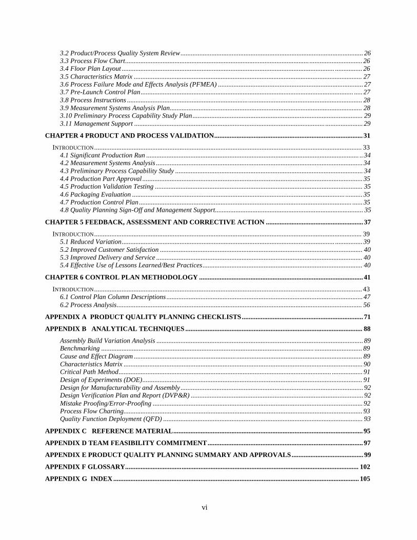
3.2 Product/Process Quality System Review ........................................................................................................... 26
3.3 Process Flow Chart............................................................................................................ ............................... 26 3.4 Floor Plan Layout ............................................................................................................................. ................ 26
3.5 Characteristics Matrix ...................................................................................................................................... 27
3.6 Process Failure Mode and Effects Analysis (PFMEA) ..................................................................................... 27 3.7 Pre-Launch Control Plan ............................................................................................................................. ..... 27
3.8 Process Instructions .......................................................................................................................................... 28
3.9 Measurement Systems Analysis Plan................................................................................................................. 28 3.10 Preliminary Process Capability Study Plan .................................................................................................... 29
3.11 Management Support ................................................................................................................ ...................... 29
CHAPTER 4 PRODUCT AND PROCESS VALIDATION....................................................................................... 31
INTRODUCTION ............................................................................................................................................................. 33
4.1 Significant Production Run ............................................................................................................................. .. 34 4.2 Measurement Systems Analysis ......................................................................................................................... 34
4.3 Preliminary Process Capability Study .............................................................................................................. 34
4.4 Production Part Approval ................................................................................................................................. 35 4.5 Production Validation Testing .......................................................................................................................... 35
4.6 Packaging Evaluation ............................................................................................................................. .......... 35
4.7 Production Control Plan ............................................................................................................................. ...... 35 4.8 Quality Planning Sign-Off and Management Support....................................................................................... 35
CHAPTER 5 FEEDBACK, ASSESSMENT AND CORRECTIVE ACTION ......................................................... 37
INTRODUCTION ............................................................................................................................................................. 39 5.1 Reduced Variation ............................................................................................................................. ................ 39
5.2 Improved Customer Satisfaction ....................................................................................................................... 40
5.3 Improved Delivery and Service ......................................................................................................................... 40 5.4 Effective Use of Lessons Learned/Best Practices .............................................................................................. 40
CHAPTER 6 CONTROL PLAN METHODOLOGY ................................................................................................ 41
INTRODUCTION ............................................................................................................................................................. 43 6.1 Control Plan Column Descriptions ................................................................................................................... 47
6.2 Process Analysis................................................................................................................................................ 56
APPENDIX A PRODUCT QUALITY PLANNING CHECKLISTS ....................................................................... 71
APPENDIX B ANALYTICAL TECHNIQUES ........................................................................................................ 88
Assembly Build Variation Analysis ......................................................................................................................... 89 Benchmarking ............................................................................................................................. ............................ 89
Cause and Effect Diagram ...................................................................................................................................... 89
Characteristics Matrix ............................................................................................................................................ 90 Critical Path Method............................................................................................................................. .................. 91
Design of Experiments (DOE)................................................................................................................................. 91
Design for Manufacturability and Assembly ........................................................................................................... 92 Design Verification Plan and Report (DVP&R) ..................................................................................................... 92
Mistake Proofing/Error-Proofing ........................................................................................................................... 92
Process Flow Charting............................................................................................................................................ 93 Quality Function Deployment (QFD) ..................................................................................................................... 93
APPENDIX C REFERENCE MATERIAL............................................................................................................... 95
APPENDIX D TEAM FEASIBILITY COMMITMENT ........................................................................................... 97
APPENDIX E PRODUCT QUALITY PLANNING SUMMARY AND APPROVALS .......................................... 99
APPENDIX F GLOSSARY......................................................................................................................................... 102
APPENDIX G INDEX ................................................................................................................................................ 105

vii
viii
Ford
Use
al
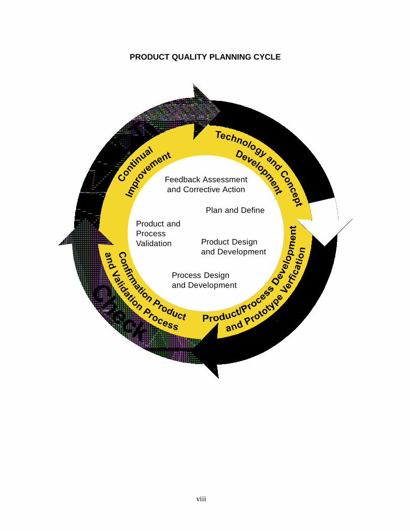
PRODUCT QUALITY PLANNING CYCLE
Feedback Assessment
and Corrective Action
Product and
Process
Validation
Plan and Define
Product Design
and Development
Process Design
and Development
Introduction
1
Introduction
The purpose of this manual is to communicate to organizations (internal
and external) and suppliers, common Product Quality Planning and
Control Plan guidelines developed jointly by Chrysler, Ford and General
Motors. This manual provides guidelines designed to produce a product
quality plan, which will support the development of a product or service
that will satisfy the customer (see Section 1.6). The following terms,
used in this edition are used to describe the supply chain. The term
"organization" refers to the unit to which these guidelines apply. The
term "supplier" replaces the term subcontractor that was used in the First
Edition. Some of the expected benefits in using these guidelines are:
• A reduction in the complexity of product quality planning for the
customers and organizations.
• A means for organizations to easily communicate product quality
planning requirements to suppliers.
This reference manual contains guidelines that support the requirements
as described in ISO/TS 16949 and applicable customer-specific
requirements. All forms in this manual are provided as examples only.
The purpose is to assist the organization’s product quality planning team
in developing the appropriate communication forms to support meeting
customer requirements, needs, and expectations.
The Product Quality Planning Cycle shown on the facing page is a
graphic depiction of a typical program. The various phases are
sequenced to represent planned timing to execute the functions
described. The purpose of the Product Quality Planning Cycle is to
emphasize:
• Up-front planning. The first three quarters of the cycle are devoted to
up-front product quality planning through product/process validation.
• The act of implementation. The fourth quarter is the stage where the
importance of evaluating the output serves two functions: to determine
if customers are satisfied, and to support the pursuit of continual
improvement.
Depicting product quality planning as a cycle illustrates the never-ending
pursuit of continual improvement that can only be achieved by taking the
experience in one program and applying that acquired knowledge to the
next program.
Introduction
2
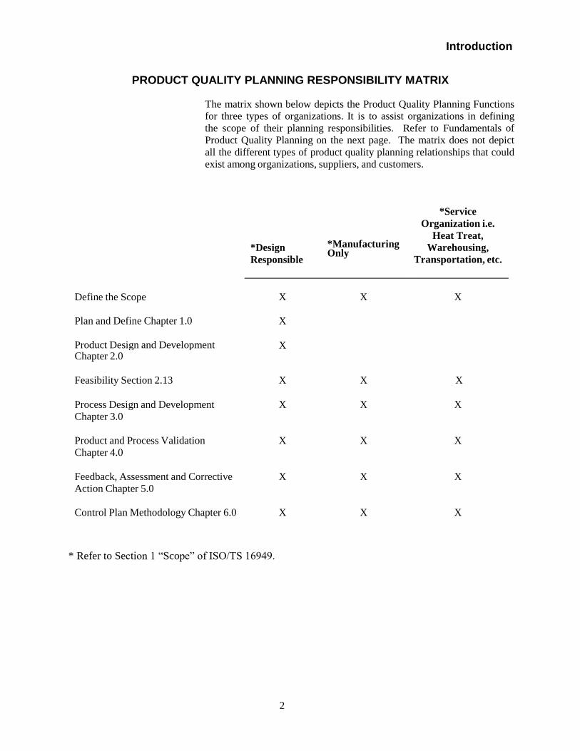
PRODUCT QUALITY PLANNING RESPONSIBILITY MATRIX
The matrix shown below depicts the Product Quality Planning Functions
for three types of organizations. It is to assist organizations in defining
the scope of their planning responsibilities. Refer to Fundamentals of
Product Quality Planning on the next page. The matrix does not depict
all the different types of product quality planning relationships that could
exist among organizations, suppliers, and customers.
*Design
Responsible
*Manufacturing Only
*Service
Organization i.e.
Heat Treat,
Warehousing,
Transportation, etc.
Define the Scope Plan and Define Chapter 1.0
Product Design and Development
X
X
X
X
X
Chapter 2.0
Feasibility Section 2.13
X
X
X
Process Design and Development
Chapter 3.0
X
X
X
Product and Process Validation
Chapter 4.0
X
X
X
Feedback, Assessment and Corrective
Action Chapter 5.0
X
X
X
Control Plan Methodology Chapter 6.0
X
X
X
* Refer to Section 1 “Scope” of ISO/TS 16949.
Introduction
3
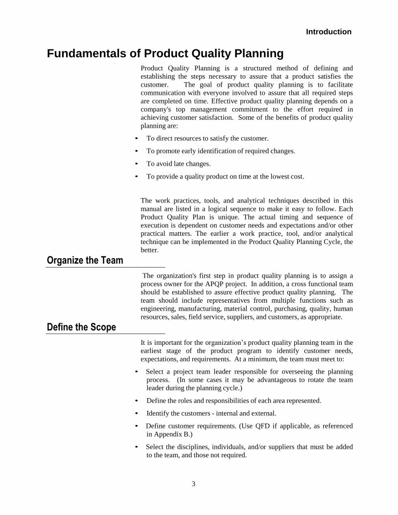
Fundamentals of Product Quality Planning
Product Quality Planning is a structured method of defining and
establishing the steps necessary to assure that a product satisfies the
customer. The goal of product quality planning is to facilitate
communication with everyone involved to assure that all required steps
are completed on time. Effective product quality planning depends on a
company's top management commitment to the effort required in
achieving customer satisfaction. Some of the benefits of product quality
planning are:
• To direct resources to satisfy the customer.
• To promote early identification of required changes.
• To avoid late changes.
• To provide a quality product on time at the lowest cost.
Organize the Team
Define the Scope
The work practices, tools, and analytical techniques described in this
manual are listed in a logical sequence to make it easy to follow. Each
Product Quality Plan is unique. The actual timing and sequence of
execution is dependent on customer needs and expectations and/or other
practical matters. The earlier a work practice, tool, and/or analytical
technique can be implemented in the Product Quality Planning Cycle, the
better.
The organization's first step in product quality planning is to assign a
process owner for the APQP project. In addition, a cross functional team
should be established to assure effective product quality planning. The
team should include representatives from multiple functions such as
engineering, manufacturing, material control, purchasing, quality, human
resources, sales, field service, suppliers, and customers, as appropriate.
It is important for the organization’s product quality planning team in the
earliest stage of the product program to identify customer needs,
expectations, and requirements. At a minimum, the team must meet to:
• Select a project team leader responsible for overseeing the planning
process. (In some cases it may be advantageous to rotate the team leader during the planning cycle.)
• Define the roles and responsibilities of each area represented.
• Identify the customers - internal and external.
• Define customer requirements. (Use QFD if applicable, as referenced
in Appendix B.)
• Select the disciplines, individuals, and/or suppliers that must be added
to the team, and those not required.
Introduction
4
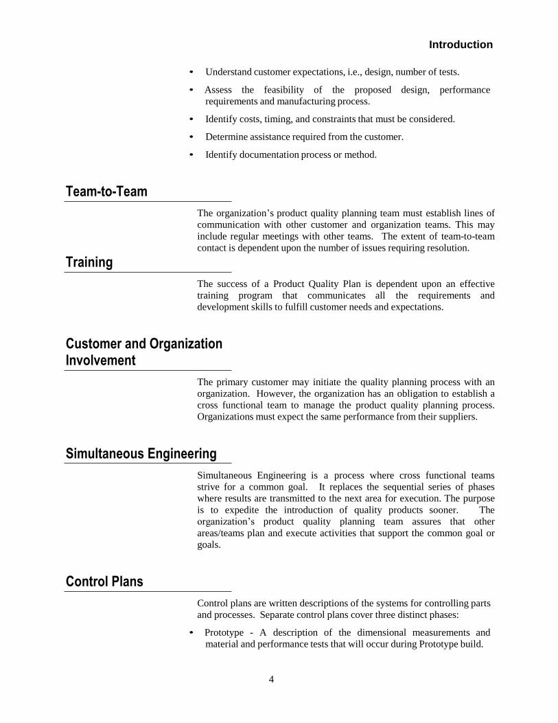
• Understand customer expectations, i.e., design, number of tests.
• Assess the feasibility of the proposed design, performance
requirements and manufacturing process.
• Identify costs, timing, and constraints that must be considered.
• Determine assistance required from the customer.
• Identify documentation process or method.
Team-to-Team
Training
The organization’s product quality planning team must establish lines of
communication with other customer and organization teams. This may
include regular meetings with other teams. The extent of team-to-team
contact is dependent upon the number of issues requiring resolution.
The success of a Product Quality Plan is dependent upon an effective
training program that communicates all the requirements and
development skills to fulfill customer needs and expectations.
Customer and Organization Involvement
The primary customer may initiate the quality planning process with an
organization. However, the organization has an obligation to establish a
cross functional team to manage the product quality planning process.
Organizations must expect the same performance from their suppliers.
Simultaneous Engineering
Simultaneous Engineering is a process where cross functional teams
strive for a common goal. It replaces the sequential series of phases
where results are transmitted to the next area for execution. The purpose
is to expedite the introduction of quality products sooner. The
organization’s product quality planning team assures that other
areas/teams plan and execute activities that support the common goal or
goals.
Control Plans
Control plans are written descriptions of the systems for controlling parts
and processes. Separate control plans cover three distinct phases:
• Prototype - A description of the dimensional measurements and
material and performance tests that will occur during Prototype build.

Introduction
5
• Pre-launch - A description of the dimensional measurements and
material and performance tests that will occur after Prototype and
before full Production.
• Production - A comprehensive documentation of product/process characteristics, process controls, tests, and measurement systems that
will occur during mass production.
Concern Resolution
During the planning process, the team will encounter product design
and/or processing concerns. These concerns should be documented on a
matrix with assigned responsibility and timing. Disciplined problem-
solving methods are recommended in difficult situations. Analytical
techniques described in Appendix B should be used as appropriate.
Product Quality Timing Plan
he organization’s product quality planning team's first order of business
following organizational activities should be the development of a
Timing Plan. The type of product, complexity and customer
expectations should be considered in selecting the timing elements that
must be planned and charted. All team members should agree with each
event, action, and timing. A well-organized timing chart should list
tasks, assignments, and/or other events. (The Critical Path Method may
be appropriate; reference Appendix B.) Also, the chart provides the
planning team with a consistent format for tracking progress and setting
meeting agendas. To facilitate status reporting, each event must have a
"start" and a "completion" date with the actual point of progress
recorded. Effective status reporting supports program monitoring with a
focus on identifying items that require special attention.
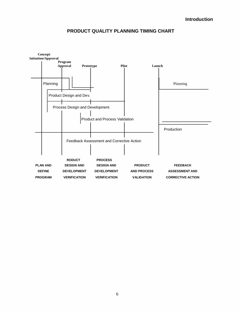
Plans Relative to the Timing Chart
The success of any program depends on meeting customer needs and
expectations in a timely manner at a cost that represents value. The
Product Quality Planning Timing Chart below and the Product Quality
Planning Cycle described previously require a planning team to
concentrate its efforts on problem prevention. Problem prevention is
driven by Simultaneous Engineering performed by product and
manufacturing engineering activities working concurrently. Planning
teams must be prepared to modify product quality plans to meet
customer expectations. The organization’s product quality planning
team is responsible for assuring that timing meets or exceeds the
customer timing plan.
Introduction
6
PLAN AND
DEFINE
DESIGN AND
DEVELOPMENT
DESIGN AND
DEVELOPMENT
PRODUCT
AND PROCESS
FEEDBACK
ASSESSMENT AND
PROGRAM VERIFICATION VERIFICATION VALIDATION CORRECTIVE ACTION
PRODUCT QUALITY PLANNING TIMING CHART
Concept
Initiation/Approval Program
Approval Prototype Pilot Launch
Planning Planning
Product Design and Dev.
Process Design and Development
Product and Process Validation
Production
Feedback Assessment and Corrective Action
RODUCT PROCESS
7
Chapter 1 Plan and Define
Chapter I Plan and Define Program
8
Chapter 1 Plan and Define
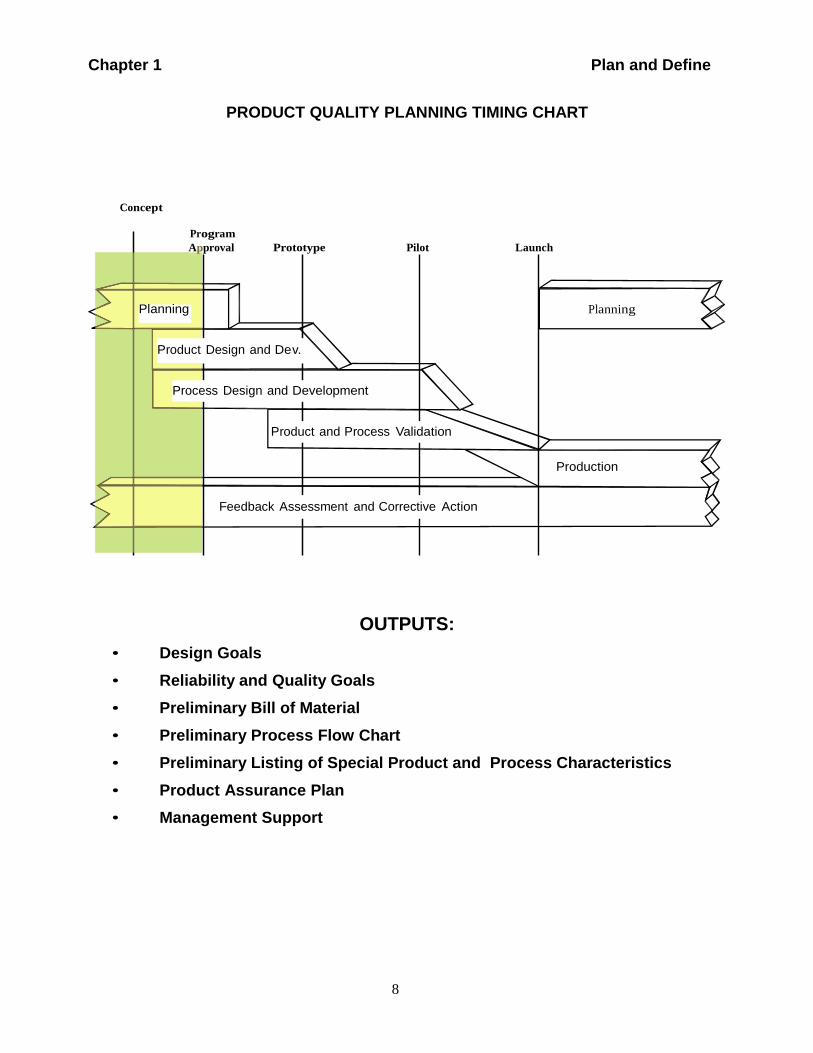
PRODUCT QUALITY PLANNING TIMING CHART
Concept
Program
Appproval Prototype Pilot Launch
Planning Planning
Product Design and Dev.
Process Design and Development
Product and Process Validation
Production
Feedback Assessment and Corrective Action
• Design Goals
OUTPUTS:
• Reliability and Quality Goals
• Preliminary Bill of Material
• Preliminary Process Flow Chart
• Preliminary Listing of Special Product and Process Characteristics
• Product Assurance Plan
• Management Support
9
Chapter 1 Plan and Define
Introduction
This chapter describes how customer needs and expectations are linked to
planning and defining a quality program. The goal of any product program
is meeting customer needs while providing competitive value. The initial
step of the product quality planning process is to ensure that customer needs
and expectations are clearly understood.
The inputs and outputs applicable to the planning process may vary
according to the product development process, and customer needs and
expectations. Some recommendations discussed in this chapter are as
follows:
INPUTS
• Voice of the Customer
○ Market Research (including OEM Vehicle Build Timing and OEM
Volume Expectations)
○ Historical Warranty and Quality Information
○ Team Experience
• Business Plan/Marketing Strategy
• Product/Process Benchmark Data
• Product/Process Assumptions
• Product Reliability Studies
• Customer Inputs
OUTPUTS (Become inputs for Chapter 2)
• Design Goals
• Reliability and Quality Goals
• Preliminary Bill of Material
• Preliminary Process Flow Chart
• Preliminary Listing of Special Product and Process Characteristics
• Product Assurance Plan
• Management Support (including program timing and planning for
resources and staffing to support required capacity)
1.1 Voice of the Customer
The "Voice of the Customer" encompasses complaints, recommendations,
data and information obtained from internal and/or external customers.
Some methods for gathering this information appear in the following
paragraphs.
10
Chapter 1 Plan and Define
1.1.1 Market Research
The organization’s product quality planning team may need to obtain
market research data and information reflecting the Voice of the Customer.
The following sources can assist in identifying customer concerns and
wants and translating those concerns into product and process
characteristics:
• Customer interviews
• Customer questionnaires and surveys
• Market test and positioning reports
• New product quality and reliability studies
• Competitive product quality studies
• Best Practices
• Lessons Learned
1.1.2 Historical Warranty and Quality Information
A list of historical customer concerns and wants should be prepared to
assess the potential for recurrence during the design, manufacture,
installation and use of the product. These should be considered as an
extension of the other design requirements and included in the analysis of
customer needs.
Many of the following items can assist the team in identifying customer
concerns and wants and prioritizing appropriate resolutions.
• Best Practices
• Lessons Learned
• Warranty reports
• Capability indicators
• Supplier plant internal quality reports
• Problem resolution reports
• Customer plant returns and rejections
• Field return product analysis
1.1.3 Team Experience
The team may use any source of any information as appropriate, including
the following:
• Input from higher system level or past Quality Function Deployment
(QFD) projects
• Media commentary and analysis: magazine and newspaper reports, etc.
11
Chapter 1 Plan and Define
• Customer letters and suggestions
• Best Practices
• Lessons Learned
• Dealer comments
• Fleet Operator's comments
• Field service reports
• Internal evaluations using surrogate customers
• Road trips
• Management comments or direction
• Problems and issues reported from internal customers
• Government requirements and regulations
• Contract review
1.2 Business Plan and Marketing Strategy
The customer business plan and marketing strategy will set the framework
for the product quality plan. The business plan may place constraints (e.g.,
timing, cost, investment, product positioning, research and development
(R&D) resources) on the team that affect the direction taken. The
marketing strategy will define the target customer, the key sales points, and
key competitors.
1.3 Product/Process Benchmark Data
The use of benchmarking (referenced in Appendix B) will provide input to
establishing product/process performance targets. Research and
development may also provide benchmarks and concept ideas. One method
to successful benchmarking is:
• Identify the appropriate benchmarks.
• Understand the reason for the gap between your current status and the
benchmark.
• Develop a plan to close the gap, match the benchmark, or exceed the
benchmark.
12
Chapter 1 Plan and Define
1.4 Product/Process Assumptions
There will be assumptions that the product has certain features, design, or
process concepts. These include technical innovations, advanced materials,
reliability assessments, and new technology. All should be utilized as
inputs.
1.5 Product Reliability Studies
This type of data considers frequency of repair or replacement of
components within designated periods of time and the results of long-term
reliability/durability tests.
1.6 Customer Inputs
The next users of the product can provide valuable information relating to
their needs and expectations. In addition, the next product users may have
already conducted some or all of the aforementioned reviews and studies.
These inputs should be used by the customer and/or organization to develop
agreed upon measures of customer satisfaction.
1.7 Design Goals
Design goals are a translation of the Voice of the Customer into measurable
design objectives. The proper selection of design goals assures that the
Voice of the Customer is not lost in subsequent design activity. The Voice
of the Customer also includes regulatory requirements such as materials
composition reporting and polymeric part marking.
1.8 Reliability and Quality Goals
Reliability goals are established based on customer wants and expectations,
program objectives, and reliability benchmarks. An example of customer
wants and expectations could include no safety failures. Some reliability
benchmarks could be competitor product reliability, warranty data, or
frequency of repair over a set time period. Quality goals should be based
on metrics such as parts per million, problem levels, or scrap reduction.
1.9 Preliminary Bill of Material
The team should establish a preliminary bill of material based on
product/process assumptions and include a potential supplier list. In order
to identify the preliminary special product/process characteristics it is
necessary to have selected the appropriate design and manufacturing
process.
13
Chapter 1 Plan and Define
1.10 Preliminary Process Flow Chart
The anticipated manufacturing process should be described using a process
flow chart developed from the preliminary bill of material and
product/process assumptions.
1.11 Preliminary Identification of Special Product and Process Characteristics
Special product and process characteristics are identified by the customer in
addition to those selected by the organization through knowledge of the
product and process. Examples of input to identification of special
characteristics include:
• Product assumptions based on the analysis of customer needs and
expectations.
• Identification of reliability goals and requirements.
• Identification of special process characteristics from the anticipated
manufacturing process.
• Similar part FMEAs.
1.12 Product Assurance Plan
The Product Assurance Plan translates design goals into design
requirements and is based on customer needs and expectations. This
manual does not require a specific method for preparing a Product
Assurance Plan. The Product Assurance Plan can be developed in any
format understood by the organization and should include:
• Outlining of program requirements.
• Identification of reliability, durability, and apportionment/allocation goals
and/or requirements.
• Assessment of new technology, complexity, materials, application,
environment, packaging, service, and manufacturing requirements, or any
other factor that may place the program at risk.
• Use of Failure Mode and Effects Analysis (FMEA).
• Development of preliminary engineering requirements.
14
Chapter 1 Plan and Define
1.13 Management Support
One of the keys to the success of Advanced Product Quality Planning is the
interest, commitment and support of upper management. Participation by
management in product quality planning meetings is vital to ensuring the
success of the program. Management should be updated at the conclusion of
every product quality planning phase to reinforce their commitment and
support. Updates and/or requests for assistance can occur more frequently
as required. A primary goal of Advanced Product Quality Planning is to
maintain management support by demonstrating that all planning
requirements have been met and/or concerns documented and scheduled for
resolution, including program timing and planning for resources and
staffing to support required capacity.
15
Chapter 2 Product Design and Development
Chapter 2 Product Design and Development
16
Chapter 2 Product Design and Development
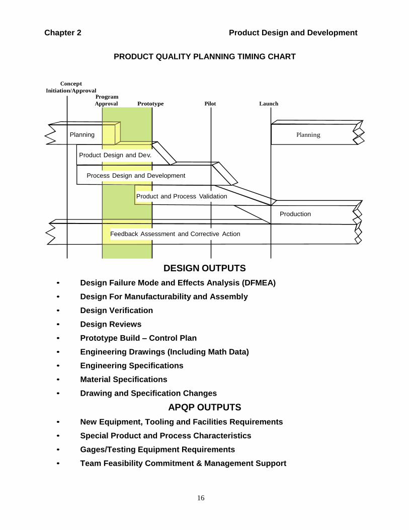
PRODUCT QUALITY PLANNING TIMING CHART
Concept
Initiation/Approval Program
Approval Prototype Pilot Launch
Planning Planning
Product Design and Dev.
Process Design and Development
Product and Process Validation
Production
Feedback Assessment and Corrective Action
DESIGN OUTPUTS
• Design Failure Mode and Effects Analysis (DFMEA)
• Design For Manufacturability and Assembly
• Design Verification
• Design Reviews
• Prototype Build – Control Plan
• Engineering Drawings (Including Math Data)
• Engineering Specifications
• Material Specifications
• Drawing and Specification Changes
APQP OUTPUTS
• New Equipment, Tooling and Facilities Requirements
• Special Product and Process Characteristics
• Gages/Testing Equipment Requirements
• Team Feasibility Commitment & Management Support
17
Chapter 2 Product Design and Development
Introduction
This chapter discusses the elements of the planning process during which
design features and characteristics are developed into a near final form. All
design factors should be considered by the organization in the Advanced
Product Quality Planning process even if the design is owned by the
customer or shared. The steps include prototype build to verify that the
product or service meets the objectives of the Voice of the Customer. A
feasible design must permit meeting production volumes and schedules, and
be consistent with the ability to meet engineering requirements, along with
quality, reliability, investment cost, weight, unit cost and timing objectives.
Although feasibility studies and control plans are primarily based on
engineering drawings and specification requirements, valuable information
can be derived from the analytical tools described in this chapter to further
define and prioritize the characteristics that may need special product and
process controls.
In this chapter, the Product Quality Planning Process is designed to assure a
comprehensive and critical review of engineering requirements and other
related technical information. At this stage of the process, a preliminary
feasibility analysis will be made to assess the potential problems that could
occur during manufacturing.
The inputs and outputs applicable to this chapter are as follows:
INPUTS (Derived from the outputs of Chapter 1)
• Design Goals
• Reliability and Quality Goals
• Preliminary Bill of Material
• Preliminary Process Flow Chart
• Preliminary Listing of Special Product and Process Characteristics
• Product Assurance Plan
• Management Support
DESIGN OUTPUTS (Become inputs for Chapter 3)
• Design Failure Mode and Effects Analysis (DFMEA)
• Design for Manufacturability and Assembly
• Design Verification
• Design Reviews
• Prototype Build - Control Plan
• Engineering Drawings (Including Math Data)
• Engineering Specifications
• Material Specifications
• Drawing and Specification Changes
18
Chapter 2 Product Design and Development
APQP OUTPUTS (Becomes Inputs for Chapter 3)
• New Equipment, Tooling and Facilities Requirements
• Special Product and Process Characteristics
• Gages/Testing Equipment Requirements
• Team Feasibility Commitment and Management Support
2.1 Design Failure Mode and Effects Analysis (DFMEA)
The DFMEA is a disciplined analytical technique that assesses the
probability of failure as well as the effect of such failure. A DFMEA is a
living document continually updated as customer needs and expectations
require. The DFMEA is an important input to the APQP process that may
include previously selected product and process characteristics. The
Chrysler, Ford and General Motors Potential Failure Mode and Effects
Analysis (FMEA) reference manual provides guidance for the preparation
of a DFMEA. The Design FMEA Checklist in Appendix A-1 should also
be reviewed to assure that the appropriate design characteristics have been
considered.
2.2 Design for Manufacturability and Assembly
Design for Manufacturability and Assembly is a Simultaneous Engineering
process designed to optimize the relationship between design function,
manufacturability, and ease of assembly. The scope of customer needs and
expectations defined in Chapter 1 will determine the extent of the
organization's product quality planning team involvement in this activity.
This manual does not include or refer to a formal method of preparing a
Design for Manufacturability and Assembly Plan. At a minimum, the items
listed here should be considered by the organization’s product quality
planning team:
• Design, concept, function, and sensitivity to manufacturing variation
• Manufacturing and/or assembly process
• Dimensional tolerances
• Performance requirements
• Number of components
• Process adjustments
• Material handling
19
Chapter 2 Product Design and Development
The above list may be augmented based on the organization’s product
quality planning team's knowledge, experience, the product/process,
government regulations, and service requirements.
2.3 Design Verification
Design verification verifies that the product design meets the customer
requirements derived from the activities described in Chapter 1.
2.4 Design Reviews
Design reviews are regularly scheduled meetings led by the organization's
design engineering activity and must include other affected areas. The
design review is an effective method to prevent problems and
misunderstandings; it also provides a mechanism to monitor progress,
report to management, and obtain customer approval as required.
Design reviews are a series of verification activities that are more than an
engineering inspection. At a minimum, design reviews should include
evaluation of:
• Design/Functional requirement(s) considerations
• Formal reliability and confidence goals
• Component/subsystem/system duty cycles
• Computer simulation and bench test results
• DFMEA(s)
• Review of the Design for Manufacturability and Assembly effort
• Design of Experiments (DOE) and assembly build variation results (Refer
to Appendix B.)
• Test failures
• Design verification progress
A major function of design reviews is the tracking of design verification
progress. The organization should track design verification progress
through the use of a plan and report format, referred to as Design
Verification Plan and Report (DVP&R) by some customers. The plan and
report is a formal method to assure:
• Design verification
• Product and process validation of components and assemblies through the
application of a comprehensive test plan and report.
The organization’s product quality planning team is not limited to the items
listed. The team should consider and use as appropriate, the analytical
techniques listed in Appendix B.
20
Chapter 2 Product Design and Development
2.5 Prototype Build - Control Plan
Prototype control plans are a description of the dimensional measurements
and material and functional tests that will occur during prototype build. The
organization’s product quality planning team should ensure that a prototype
control plan is prepared. Control plan methodology is described in Chapter
6. A Control Plan Checklist is provided in both Section 6 and Appendix A-8
to assist in the preparation of the prototype control plan.
The manufacture of prototype parts provides an excellent opportunity for
the team and the customer to evaluate how well the product or service
meets the Voice of the Customer objectives. It is the organization’s product
quality planning team's responsibility to review prototypes for the
following:
• Assure that the product or service meets specification and report data as
required.
• Ensure that particular attention has been given to special product and
process characteristics.
• Use data and experience to establish preliminary process parameters and
packaging requirements.
• Communicate any concerns, deviations, and/or cost impact to the
customer.
2.6 Engineering Drawings (Including Math Data)
Customer designs do not preclude the organization’s product quality
planning team's responsibility to review engineering drawings in the
following manner. Engineering drawings may include special
(governmental regulatory and safety) characteristics that must be shown on
the control plan. When customer engineering drawings are nonexistent, the
controlling drawings should be reviewed by the team to determine which
characteristics affect fit, function, durability and/or governmental regulatory
safety requirements.
Drawings should be reviewed to determine if there is sufficient information
for a dimensional layout of the individual parts. Control or datum
surfaces/locators should be clearly identified so that appropriate functional
gages and equipment can be designed for ongoing controls. Dimensions
should be evaluated to assure feasibility and compatibility with industry
manufacturing and measuring standards. If appropriate, the team should
assure that math data is compatible with the customer's system for effective
two-way communications.
21
Chapter 2 Product Design and Development
2.7 Engineering Specifications
A detailed review and understanding of the controlling specifications will
help the organization’s product quality planning team to identify the
functional, durability and appearance requirements of the subject
component or assembly. Sample size, frequency, and acceptance criteria of
these parameters are generally defined in the in-process test section of the
Engineering Specification. Otherwise, the sample size and frequency are to
be determined by the organization and listed in the control plan. In either
case, the organization should determine which characteristics affect meeting
functional, durability, and appearance requirements.
2.8 Material Specifications
In addition to drawings and performance specifications, material
specifications should be reviewed for special characteristics relating to
physical properties, performance, environmental, handling, and storage
requirements. These characteristics should also be included in the control
plan.
2.9 Drawing and Specification Changes
Where drawing and specification changes are required, the team must
ensure that the changes are promptly communicated and properly
documented to all affected areas.
2.10 New Equipment, Tooling and Facilities Requirements
The DFMEA, Product Assurance Plan and/or design reviews may identify
new equipment and facilities including meeting capacity requirements. The
organization’s product quality planning team should address these
requirements by adding the items to the Timing Chart. The team should
assure that there is a process to determine that new equipment and tooling is
capable and delivered on time. Facilities progress should be monitored to
assure completion prior to planned production tryout. Refer to the New
Equipment, Tooling and Test Equipment Checklist in Appendix A-3.
2.11 Special Product and Process Characteristics
In the Plan and Define Program stage (Chapter 1), the team identified
preliminary special product and process characteristics. The organization’s
product quality planning team should build on this listing and reach
consensus through the evaluation of the technical information. The
organization should refer to the appropriate customer-specific requirements
22
Chapter 2 Product Design and Development
for additional details on the use of special product and process
characteristics. The consensus is to be documented on the appropriate
control plan. The Control Plan Special Characteristics and Data Point
Coordinates forms referenced in Chapter 6, Supplements K and L, are
recommended methods to document and update special characteristics. The
organization can use any form that meets the documentation requirements.
Refer to customer-specific requirements for unique approval requirements
2.12 Gages/Testing Equipment Requirements
Gages/testing equipment requirements may also be identified at this time.
The organization’s product quality planning team should add these
requirements to the Timing Chart. Progress should be monitored to assure
that required timing is met.
2.13 Team Feasibility Commitment and Management Support
The organization’s product quality planning team must assess the feasibility
of the proposed design at this time. Customer design ownership does not
preclude the organization's obligation to assess design feasibility. The team
must be satisfied that the proposed design can be manufactured, assembled,
tested, packaged, and delivered in sufficient quantity on schedule at an
acceptable cost to the customer. The Design Information Checklist in
Appendix A-2 allows the team to review its efforts in this section and make
an evaluation of effectiveness. This checklist will also serve as a basis for
the open issues discussed in the Team Feasibility Commitment, Appendix
D. The team consensus that the proposed design is feasible should be
documented along with all open issues that require resolution and presented
to management for their support. The Team Feasibility Commitment form
shown in Appendix D is an example of the type of written record
recommended.

23
Chapter 3 Process Design and Development
Chapter 3 Process Design and Development
24
Chapter 3 Process Design and Development
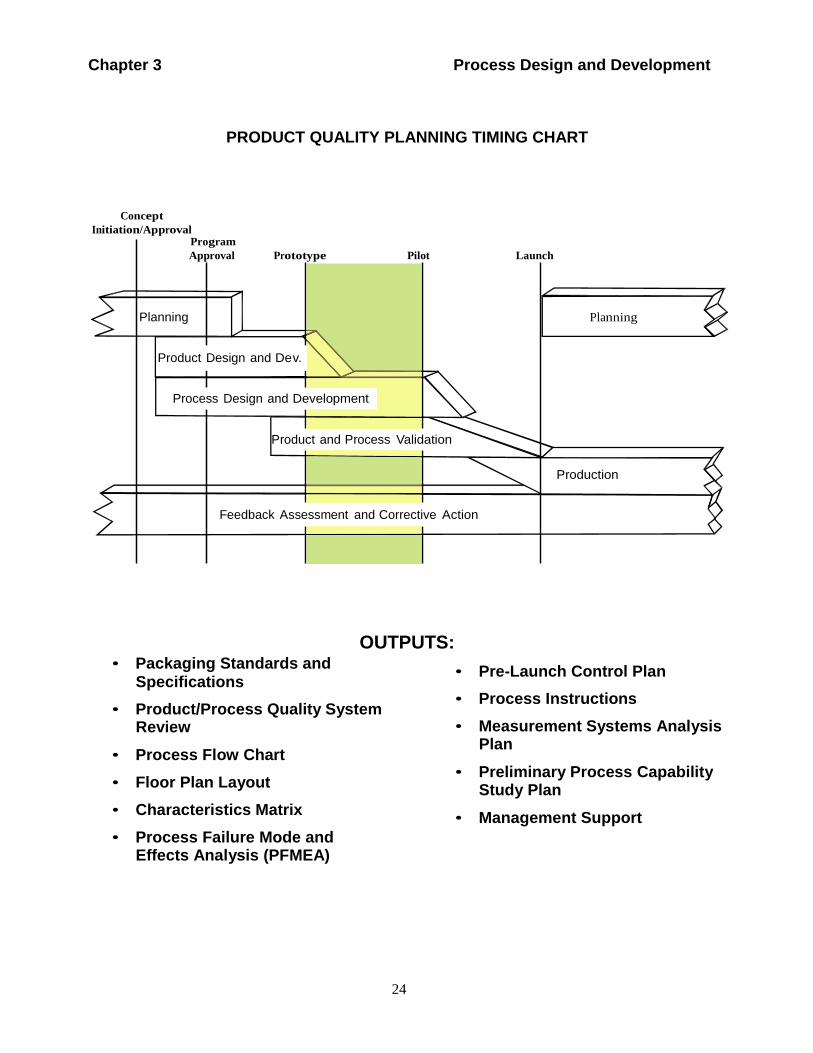
PRODUCT QUALITY PLANNING TIMING CHART
Concept
Initiation/Approval Program
Approval Prototype Pilot Launch
Planning Planning
Product Design and Dev.
Process Design and Development
Product and Process Validation
Production
Feedback Assessment and Corrective Action
• Packaging Standards and Specifications
OUTPUTS: • Pre-Launch Control Plan
• Product/Process Quality System Review
• Process Flow Chart
• Floor Plan Layout
• Characteristics Matrix
• Process Failure Mode and Effects Analysis (PFMEA)
• Process Instructions
• Measurement Systems Analysis Plan
• Preliminary Process Capability Study Plan
• Management Support

25
Chapter 3 Process Design and Development
Introduction
This chapter discusses the major features of developing a manufacturing
system and its related control plans to achieve quality products. The tasks
to be accomplished at this step of the product quality planning process
depend upon the successful completion of the prior stages contained in the
first two sections. This next step is designed to ensure the comprehensive
development of an effective manufacturing system. The manufacturing
system must assure that customer requirements, needs and expectations are
met. The inputs and outputs applicable to the process step in this chapter are
as follows:
INPUTS (Derived from the outputs of Chapter 2)
• Design Failure Mode and Effects Analysis (DFMEA)
• Design for Manufacturability and Assembly
• Design Verification
• Design Reviews
• Prototype Build - Control Plan
• Engineering Drawings (Including Math Data)
• Engineering Specifications
• Material Specifications
• Drawing and Specification Changes
• New Equipment, Tooling and Facilities Requirements
• Special Product and Process Characteristics
• Gages/Testing Equipment Requirements
• Team Feasibility Commitment and Management Support
OUTPUTS (Become inputs for Chapter 4)
• Packaging Standards & Specifications
• Product/Process Quality System Review
• Process Flow Chart
• Floor Plan Layout
• Characteristics Matrix
• Process Failure Mode and Effects Analysis (PFMEA)
• Pre-Launch Control Plan (including Error-Proofing Devices)
• Process Instructions
• Measurement Systems Analysis Plan
• Preliminary Process Capability Study Plan
• Management Support (including operator staffing and training plan)
26
Chapter 3 Process Design and Development
3.1 Packaging Standards and Specifications
The customer will usually have packaging requirements that should be
incorporated into any packaging specifications for the product. If none are
provided, the packaging design should ensure product integrity at point of
use. The organization’s product quality planning team should ensure that
individual product packaging (including interior partitions) is designed and
developed. Customer packaging standards or generic packaging
requirements should be used when appropriate. In all cases the packaging
design should assure that the product performance and characteristics will
remain unchanged during packing, transit, and unpacking. The packaging
should have compatibility with all identified material handling equipment
including robots.
3.2 Product/Process Quality System Review
The organization’s product quality planning team should review the
manufacturing site(s) Quality Management System. Any additional controls
and/or procedural changes required to produce the product should be
updated, documented and included in the manufacturing control plan. This
is an opportunity for the organization’s product quality planning team to
improve the existing quality system based on customer input, team
expertise, and previous experience. The Product/Process Quality Checklist
provided in Appendix A-4 can be used by the organization’s product quality
planning team to verify completeness.
3.3 Process Flow Chart
The process flow chart is a schematic representation of the current or
proposed process flow. It can be used to analyze sources of variations of
machines, materials, methods, and manpower from the beginning to end of
a manufacturing or assembly process. It is used to emphasize the impact of
sources of variation on the process. The flow chart helps to analyze the total
process rather than individual steps in the process. The flow chart assists
the organization’s product quality planning team to focus on the process
when conducting the PFMEA and designing the Control Plan. The Process
Flow Chart Checklist in Appendix A-6 can be used by the organization’s
product quality planning team to verify completeness.
3.4 Floor Plan Layout
The floor plan should be developed and reviewed to determine the
acceptability of important control items, such as inspection points, control
chart location, applicability of visual aids, interim repair stations, and
27
Chapter 3 Process Design and Development
storage areas to contain non-conforming material. All material flow should
be keyed to the process flow chart and control plan. The Floor Plan
Checklist in Appendix A-5 can be used by the organization’s product
quality planning team to verify completeness. The floor plan layout should
be developed in such a manner to optimize the material travel, handling and
value-added use of floor space and should facilitate the synchronous flow of
materials through the process.
3.5 Characteristics Matrix
A characteristics matrix is a recommended analytical technique for
displaying the relationship between process parameters and manufacturing
stations. See Analytical Techniques in Appendix B for further detail.
3.6 Process Failure Mode and Effects Analysis (PFMEA)
A PFMEA should be conducted during product quality planning and before
beginning production. It is a disciplined review and analysis of a new or
revised process and is conducted to anticipate, resolve, or monitor potential
process problems for a new or revised product program. For further
information on the creation and maintenance of PFMEAs refer to Chrysler,
Ford and General Motors Potential Failure Mode and Effects Analysis
(FMEA) reference manual. The Process FMEA Checklist in Appendix A-7
can be used by the organization’s product quality planning team to verify
completeness.
3.7 Pre-Launch Control Plan
Pre-launch control plans are a description of the dimensional measurements
and material and functional tests that will occur after prototype and before
full production. The pre-launch control plan should include additional
product/process controls to be implemented until the production process is
validated. The purpose of the pre-launch control plan is to contain potential
non-conformities during or prior to initial production runs. Examples of
enhancements in the pre-launch control plan are:
• More frequent inspection
• More in-process and final check points
• Robust statistical evaluations
• Enhanced audits
• Identification of error-proofing devices
For further information on the creation and maintenance of control plans
refer to Chapter 6. The Control Plan Checklist in Appendix A-8 can be

28
Chapter 3 Process Design and Development
used by the organization’s product quality planning team to verify
completeness.
3.8 Process Instructions
The organization’s product quality planning team should ensure that
process instructions provide sufficient understanding and detail for all
personnel who have direct responsibility for the operation of the processes.
These instructions should be developed from the following sources:
• FMEAs
• Control plan(s)
• Engineering drawings, performance specifications, material
specifications, visual standards and industry standards
• Process flow chart
• Floor plan layout
• Characteristics matrix
• Packaging Standards and Specifications
• Process parameters
• Organization expertise and knowledge of the processes and products
• Handling requirements
• Operators of the process
The process instructions for standard operating procedures should be posted
and should include set-up parameters such as: machine speeds, feeds, cycle
times, and tooling, and should be accessible to the operators and
supervisors. Additional information for process instruction preparation may
be found in appropriate customer-specific requirements.
3.9 Measurement Systems Analysis Plan
The organization’s product quality planning team should ensure that a plan
to accomplish the required measurement systems analysis is developed,
including checking aids. This plan should include, at a minimum, a
laboratory scope appropriate for the required measurements and tests, the
responsibility to ensure gage linearity, accuracy, repeatability,
reproducibility, and correlation for duplicate gages. Refer to the Chrysler,
Ford, and General Motors Measurement Systems Analysis (MSA) reference
manual.
29
Chapter 3 Process Design and Development
3.10 Preliminary Process Capability Study Plan
The organization’s product quality planning team should ensure the
development of a preliminary process capability plan. The characteristics
identified in the control plan will serve as the basis for the preliminary
process capability study plan. Reference the Chrysler, Ford, and General
Motors Production Part Approval Process (PPAP) manual and Chrysler,
Ford, and General Motors Statistical Process Control (SPC) reference
manual for further definition.
3.11 Management Support
The organization’s product quality planning team should schedule a formal
review designed to reinforce management commitment at the conclusion of
the process design and development phase. This review is critical to
keeping upper management informed as well as gaining assistance to assist
in resolution of any open issues. Management support includes the
confirmation of the planning and providing the resources and staffing to
meet the required capacity.

Chapter 3 Process Design and Development
30
Chapter 4 Product and Process Validation
31
Chapter 4 Product and Process Validation
Chapter 4 Product and Process Validation
32
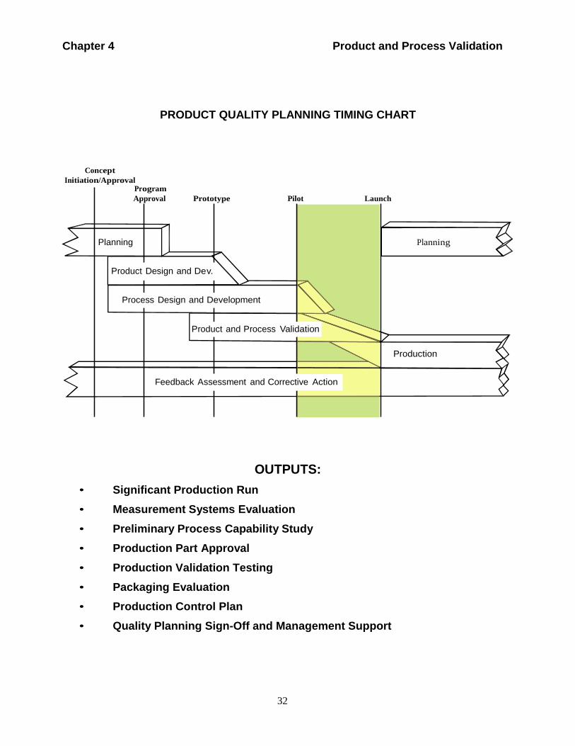
PRODUCT QUALITY PLANNING TIMING CHART
Concept
Initiation/Approval Program
Approval Prototype Pilot Launch
Planning Planning
Product Design and Dev.
Process Design and Development
Product and Process Validation
Production
Feedback Assessment and Corrective Action
OUTPUTS:
• Significant Production Run
• Measurement Systems Evaluation
• Preliminary Process Capability Study
• Production Part Approval
• Production Validation Testing
• Packaging Evaluation
• Production Control Plan
• Quality Planning Sign-Off and Management Support
Chapter 4 Product and Process Validation
33
Introduction
This chapter discusses the major features of validating the manufacturing
process through an evaluation of a significant production run. During a
significant production run, the organization’s product quality planning team
should validate that the control plan and process flow chart are being
followed and the products meet customer requirements. Additional
concerns should be identified for investigation and resolution prior to
regular production runs.
The inputs and outputs applicable to the process steps in this chapter are as
follows:
INPUTS (Derived from the outputs of Chapter 3)
• Packaging Standards & Specifications
• Product/Process Quality System Review
• Process Flow Chart
• Floor Plan Layout
• Characteristics Matrix
• Process Failure Mode and Effects Analysis (PFMEA)
• Pre-Launch Control Plan
Process Instructions
• Measurement Systems Analysis Plan
• Preliminary Process Capability Study Plan
• Management Support
OUTPUTS (Become inputs for Chapter 5)
• Significant Production Run
• Measurement Systems Evaluation
• Preliminary Process Capability Study
• Production Part Approval
• Production Validation Testing
• Packaging Evaluation
• Production Control Plan
• Quality Planning Sign-Off and Management Support
Chapter 4 Product and Process Validation
34
4.1 Significant Production Run
The significant production run must be conducted using production tooling,
production equipment, production environment (including production
operators), facility, production gages and production rate. The validation of
the effectiveness of the manufacturing process begins with the significant
production run (refer to the Chrysler, Ford, and General Motors Production
Part Approval Process (PPAP) manual or the appropriate customer-specific
requirements for additional details). The minimum quantity for a significant
production run is usually set by the customer, but can be exceeded by the
organization’s product quality planning team. Output of the significant
production run (product) is used for:
• Preliminary process capability study
• Measurement systems analysis
• Production rate demonstration
• Process review
• Production validation testing
• Production part approval
• Packaging evaluation
• First time capability (FTC)
• Quality planning sign-off
• Sample production parts
• Master sample (as required)
4.2 Measurement Systems Analysis
The specified monitoring and measuring devices and methods should be
used to check the control plan identified characteristics to engineering
specification and be subjected to measurement system evaluation during or
prior to the significant production run. Refer to the Chrysler, Ford, and
General Motors Measurement Systems Analysis (MSA) reference manual.
4.3 Preliminary Process Capability Study
The preliminary process capability study should be performed on
characteristics identified in the control plan. The study provides an
assessment of the readiness of the process for production. Refer to the
Chrysler, Ford, and General Motors Production Part Approval Process
(PPAP) manual and Chrysler, Ford, and General Motors Statistical Process
Control (SPC) reference manual for details concerning the preliminary
Chapter 4 Product and Process Validation
35
process capability study. Refer to customer-specific requirements for
unique requirements.
4.4 Production Part Approval
PPAP's purpose is to provide the evidence that all customer engineering
design record and specification requirements are properly understood by the
organization and that the manufacturing process has the potential to produce
product consistently meeting these requirements during an actual
production run at the quoted production rate. Refer to the Chrysler, Ford,
and General Motors Production Part Approval Process (PPAP) manual.
4.5 Production Validation Testing
Production validation testing refers to engineering tests that validate that
products made from production tools and processes meet customer
engineering standards including appearance requirements.
4.6 Packaging Evaluation
ll test shipments (when required) and test methods must assess the
protection of the product from normal transportation damage and adverse
environmental factors. Customer-specified packaging does not preclude the
organization’s product quality planning team involvement in evaluating the
effectiveness of the packaging.
4.7 Production Control Plan
The production control plan is a written description of the systems for
controlling production parts and processes. The production control plan is a
living document and should be updated to reflect the addition or deletion of
controls based on experience gained by producing parts. (Approval of the
authorized customer representative may be required.) The production
control plan is a logical extension of the pre-launch control plan. Mass
production provides the organization the opportunity to evaluate output,
review the control plan and make appropriate changes. Chapter 6 and
Appendix A-8 present Control Plan Methodology and a checklist to verify
completeness.
4.8 Quality Planning Sign-Off and Management Support
The organization’s product quality planning team should perform a review
at the manufacturing location(s) and coordinate a formal sign-off. The
product quality sign-off indicates to management that the appropriate APQP
Chapter 4 Product and Process Validation
36
activities have been completed. The sign-off occurs prior to first product
shipment and includes a review of the following:
• Process Flow Charts. Verify that process flow charts exist and are being
followed.
• Control Plans. Verify that control plans exist, are available and are
followed at all times for all affected operations.
• Process Instructions. Verify that these documents contain all the special
characteristics specified in the control plan and that all PFMEA
recommendations have been addressed. Compare the process
instructions, PFMEA and process flow chart to the control plan.
• Monitoring and Measuring Devices. Where special gages, fixtures, test
equipment or devices are required per the control plan, verify gage
repeatability and reproducibility (GR&R) and proper usage. (Refer to the
Chrysler, Ford, and General Motors Measurement Systems Analysis
(MSA) reference manual for more information.)
• Demonstration of Required Capacity. Using production processes,
equipment, and personnel.
Upon completion of the sign-off, a review with management should be
scheduled to inform management of the program status and gain their
support with any open issues. The Product Quality Planning Summary and
Approval report shown in Appendix E is an example of the documentation
required to support an effective quality planning sign-off.
37
Chapter 5 Feedback, Assessment and Corrective Action
Chapter 5 Feedback, Assessment and Corrective Action
38
Chapter 5 Feedback, Assessment and Corrective Action
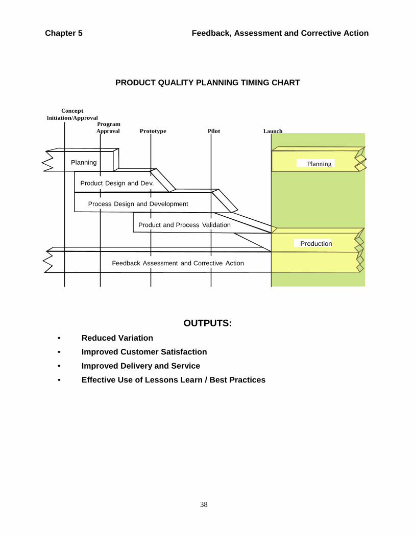
PRODUCT QUALITY PLANNING TIMING CHART
Concept
Initiation/Approval Program
Approval Prototype Pilot
Launch
Planning Planning
Product Design and Dev.
Process Design and Development
Product and Process Validation
Production
Feedback Assessment and Corrective Action
• Reduced Variation
OUTPUTS:
• Improved Customer Satisfaction
• Improved Delivery and Service
• Effective Use of Lessons Learn / Best Practices
39
Chapter 5 Feedback, Assessment and Corrective Action
Introduction
Quality planning does not end with process validation and installation. It is
the component manufacturing stage where output can be evaluated when all
special and common causes of variation are present. This is also the time to
evaluate the effectiveness of the product quality planning effort. The
production control plan is the basis for evaluating product or service at this
stage. Variable and attribute data must be evaluated. Appropriate actions
as described in the Chrysler, Ford, and General Motors Statistical Process
Control (SPC) reference manual must be taken. Organizations that fully
implement an effective APQP process will be in a better position to meet
customer requirements including any special characteristics specified by the
customer.
The inputs and outputs applicable to the process step in this chapter are as
follows:
INPUTS (Derived from the outputs of Chapter 4)
• Significant Production Run
• Measurement Systems Evaluation
• Preliminary Process Capability Study
• Production Part Approval
• Production Validation Testing
• Packaging Evaluation
• Production Control Plan
• Quality Planning Sign-Off and Management Support
OUTPUTS
• Reduced Variation
• Improved Customer Satisfaction
• Improved Delivery and Service
• Effective use of Lessons Learned/Best Practices
5.1 Reduced Variation
Control charts and other statistical techniques should be used as tools to
identify process variation. Analysis and corrective actions should be used to
reduce variation. Continual improvement requires attention not only to the
special causes of variation but understanding common causes and seeking
ways to reduce these sources of variation. Proposals should be developed
including costs, timing, and anticipated improvement for customer review.
The reduction or elimination of a common cause may provide the additional
benefit of lower costs. Organizations should be using tools such as value
analysis and reduction of variation to improve quality and reduce cost.
Refer to the Chrysler, Ford, and General Motors Statistical Process Control
40
Chapter 5 Feedback, Assessment and Corrective Action
(SPC) reference manual for details on long-term capability, special and
common causes of variation.
5.2 Improved Customer Satisfaction
Detailed planning activities and demonstrated process capability of a
product or service are important components to customer satisfaction.
However, the product or service still has to perform in the customer
environment. This product usage stage requires organization participation.
In this stage much can be learned by the organization and customer. The
effectiveness of the product quality planning efforts can also be evaluated at
this stage.
The organization and customer become partners in making the changes
necessary to correct any deficiencies and to improve customer satisfaction.
5.3 Improved Delivery and Service
The delivery and service stage of quality planning continues the
organization and customer partnership in solving problems and continual
improvement. The customer's replacement parts and service operations
must also meet requirements for quality, cost, and delivery. The goal is
first time quality. However, where problems or deficiencies occur in the
field it is essential that the organization and customer form an effective
partnership to correct the problem and satisfy the end-user customer.
The experience gained in this stage provides the customer and organization
with the necessary knowledge to reduce process, inventory, and quality
costs and to provide the right component or system for the next product.
5.4 Effective Use of Lessons Learned/Best Practices
A Lessons Learned or Best Practices portfolio is beneficial for capturing,
retaining and applying knowledge. Input to Lessons Learned and Best
Practices can be obtained through a variety of methods including:
• Review of Things Gone Right/Things Gone Wrong (TGR/TGW)
• Data from warranty and other performance metrics
• Corrective action plans
• "Read-across" with similar products and processes
• DFMEA and PFMEA studies
41
Chapter 6 Control Plan Methodology
Chapter 6 Control Plan Methodology
42
Chapter 6 Control Plan Methodology
This page intentionally left blank
43
Chapter 6 Control Plan Methodology
Introduction
The purpose of this control plan methodology is to aid in the manufacture
of quality products according to customer requirements. It does this by
providing a structured approach for the design, selection and
implementation of value-added control methods for the total system.
Control plans provide a written summary description of the systems used in
minimizing process and product variation. The intent of the control plan
form displayed in this chapter is to provide an example of how this
information can be documented. An alternate format may be used as long
as it contains the same information, as a minimum. The control plan does
not replace the information contained in detailed operator instructions. This
methodology is applicable to a wide range of manufacturing processes and
technologies. The control plan is an integral part of an overall quality
process and is to be utilized as a living document. Therefore this chapter
should be used in conjunction with other related documents.
An important phase of the process for quality planning is the development
of a control plan. A control plan is a written description of the system for
controlling parts and processes. A single control plan may apply to a group
or family of products that are produced by the same process at the same
source. Drawings and visual standards, as necessary, may be attached to the
control plan for illustration purposes. In support of a control plan, operator
and process monitoring instructions should be defined and used continually.
In effect, the control plan describes the actions that are required at each
phase of the process including receiving, in-process, out-going, and
periodic requirements to assure that all process outputs will be in a state of
control. During regular production runs, the control plan provides the
process monitoring and control methods that will be used to control
characteristics. Since processes are expected to be continually updated and
improved, the control plan reflects a strategy that is responsive to these
changing process conditions.
The control plan is maintained and used throughout the product life cycle.
Early in the product life cycle its primary purpose is to document and
communicate the initial plan for process control. Subsequently, it guides
manufacturing in how to control the process and ensure product quality.
Ultimately, the control plan remains a living document, reflecting the
current methods of control, and measurement systems used. The control
plan is updated as measurement systems and control methods are evaluated and improved.
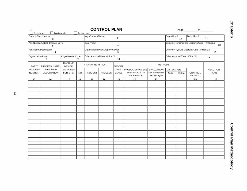
Ch
ap
ter 6
C
on
trol P
lan
Me
tho
do
log
y
44
1
Prototype
Pre-Launch
Production
CONTROL PLAN Page of
Control Plan Number
2 Key Contact/Phone
7 Date (Orig.)
10 Date (Rev.)
11
Part Number/Latest Change Level
3 Core Team
8 Customer Engineering Approval/Date (If Req'd.)
12
Part Name/Description 4
Organization/Plant Approval/Date 9
Customer Quality Approval/Date (If Req'd.) 13
Organization/Plant
5 Organization Code
6 Other Approval/Date (If Req'd.)
14 Other Approval/Date (If Req'd.)
14
PART/
PROCESS
NUMBER
PROCESS NAME/
OPERATION
DESCRIPTION
MACHINE,
DEVICE,
JIG,TOOLS
FOR MFG.
CHARACTERISTICS SPECIAL
CHAR.
CLASS
METHODS
REACTION
PLAN
NO.
PRODUCT
PROCESS PRODUCT/PROCESS
SPECIFICATION/
TOLERANCE
EVALUATION/
MEASUREMEN T
TECHNIQUE
24 SAMPLE CONTROL
METHOD SIZE FREQ.
15 16 17 18 19 20 21 22 23 25 26
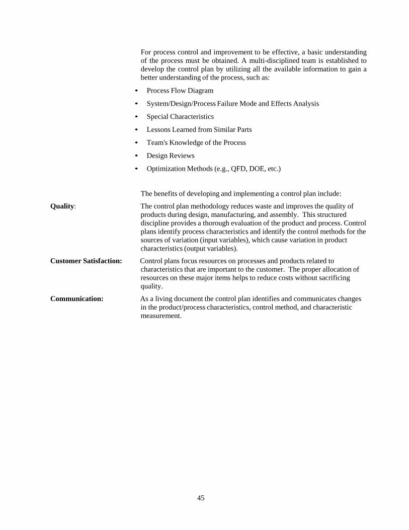
45
For process control and improvement to be effective, a basic understanding
of the process must be obtained. A multi-disciplined team is established to
develop the control plan by utilizing all the available information to gain a
better understanding of the process, such as:
• Process Flow Diagram
• System/Design/Process Failure Mode and Effects Analysis
• Special Characteristics
• Lessons Learned from Similar Parts
• Team's Knowledge of the Process
• Design Reviews
• Optimization Methods (e.g., QFD, DOE, etc.)
The benefits of developing and implementing a control plan include:
Quality: The control plan methodology reduces waste and improves the quality of
products during design, manufacturing, and assembly. This structured
discipline provides a thorough evaluation of the product and process. Control
plans identify process characteristics and identify the control methods for the
sources of variation (input variables), which cause variation in product
characteristics (output variables).
Customer Satisfaction: Control plans focus resources on processes and products related to
characteristics that are important to the customer. The proper allocation of
resources on these major items helps to reduce costs without sacrificing
quality.
Communication: As a living document the control plan identifies and communicates changes
in the product/process characteristics, control method, and characteristic
measurement.
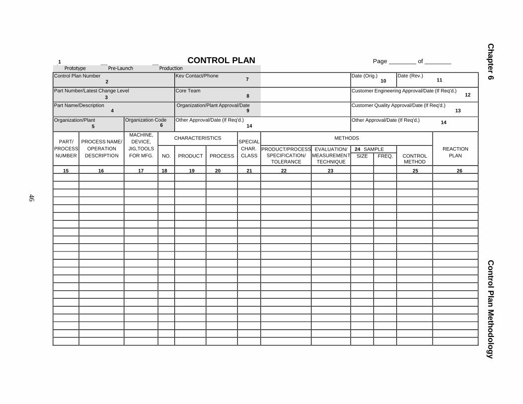
Ch
ap
ter 6
C
on
trol P
lan
Me
tho
do
log
y
46
1 CONTROL PLAN Page of
Prototype Pre-Launch Production Control Plan Number
2 Key Contact/Phone
7 Date (Orig.) 10
Date (Rev.) 11
Part Number/Latest Change Level
3 Core Team
8 Customer Engineering Approval/Date (If Req'd.) 12
Part Name/Description 4
Organization/Plant Approval/Date 9 Customer Quality Approval/Date (If Req'd.)
13
Organization/Plant
5 Organization Code
6 Other Approval/Date (If Req'd.)
14 Other Approval/Date (If Req'd.) 14
PART/
PROCESS
NUMBER
PROCESS NAME/
OPERATION
DESCRIPTION
MACHINE,
DEVICE,
JIG,TOOLS
FOR MFG.
CHARACTERISTICS SPECIAL
CHAR.
CLASS
METHODS
REACTION
PLAN
NO.
PRODUCT
PROCESS PRODUCT/PROCESS
SPECIFICATION/
TOLERANCE
EVALUATION/
MEASUREMEN T
TECHNIQUE
24 SAMPLE CONTROL METHOD
SIZE FREQ.
15 16 17 18 19 20 21 22 23 25 26
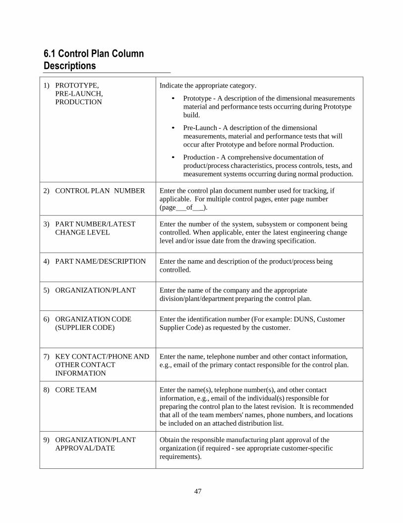
47
6.1 Control Plan Column Descriptions
1) PROTOTYPE,
PRE-LAUNCH,
PRODUCTION
Indicate the appropriate category.
• Prototype - A description of the dimensional measurements
material and performance tests occurring during Prototype
build.
• Pre-Launch - A description of the dimensional
measurements, material and performance tests that will
occur after Prototype and before normal Production.
• Production - A comprehensive documentation of
product/process characteristics, process controls, tests, and
measurement systems occurring during normal production.
2) CONTROL PLAN NUMBER
Enter the control plan document number used for tracking, if
applicable. For multiple control pages, enter page number
(page of _).
3) PART NUMBER/LATEST
CHANGE LEVEL
Enter the number of the system, subsystem or component being
controlled. When applicable, enter the latest engineering change
level and/or issue date from the drawing specification.
4) PART NAME/DESCRIPTION
Enter the name and description of the product/process being
controlled.
5) ORGANIZATION/PLANT
Enter the name of the company and the appropriate
division/plant/department preparing the control plan.
6) ORGANIZATION CODE
(SUPPLIER CODE)
Enter the identification number (For example: DUNS, Customer
Supplier Code) as requested by the customer.
7) KEY CONTACT/PHONE AND
OTHER CONTACT
INFORMATION
Enter the name, telephone number and other contact information,
e.g., email of the primary contact responsible for the control plan.
8) CORE TEAM
Enter the name(s), telephone number(s), and other contact
information, e.g., email of the individual(s) responsible for
preparing the control plan to the latest revision. It is recommended
that all of the team members' names, phone numbers, and locations
be included on an attached distribution list.
9) ORGANIZATION/PLANT
APPROVAL/DATE
Obtain the responsible manufacturing plant approval of the
organization (if required - see appropriate customer-specific
requirements).
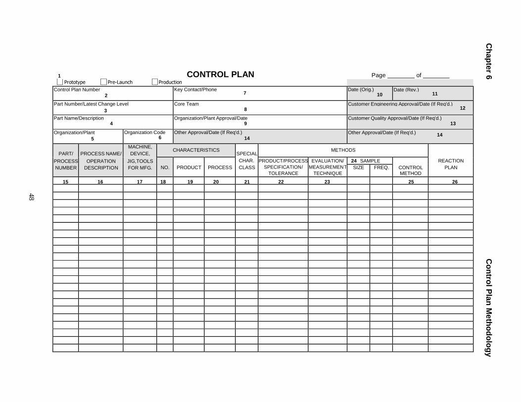
Ch
ap
ter 6
C
on
trol P
lan
Me
tho
do
log
y
48
1 CONTROL PLAN Page of
Prototype Pre-Launch Production Control Plan Number
2 Key Contact/Phone
7 Date (Orig.)
10 Date (Rev.)
11
Part Number/Latest Change Level
3 Core Team
8 Customer Engineering Approval/Date (If Req'd.)
12
Part Name/Description 4
Organization/Plant Approval/Date 9
Customer Quality Approval/Date (If Req'd.) 13
Organization/Plant
5 Organization Code
6 Other Approval/Date (If Req'd.)
14 Other Approval/Date (If Req'd.) 14
PART/
PROCESS NAME/
MACHINE,
DEVICE, CHARACTERISTICS SPECIAL
CHAR.
CLASS
METHODS
REACTION
PLAN PROCESS
NUMBER OPERATION
DESCRIPTION JIG,TOOLS
FOR MFG.
NO.
PRODUCT
PROCESS PRODUCT/PROCESS
SPECIFICATION/
TOLERANCE
EVALUATION/
MEASUREMEN T
TECHNIQUE
24 SAMPLE CONTROL METHOD
SIZE FREQ.
15 16 17 18 19 20 21 22 23 25 26
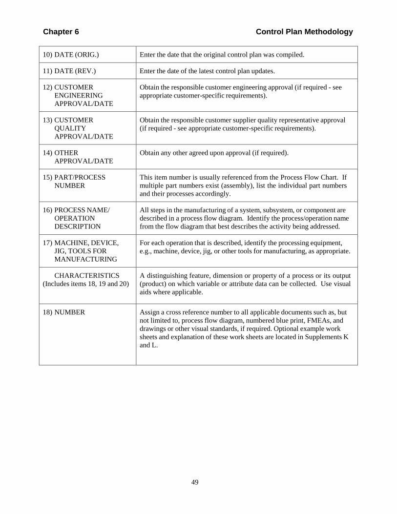
Chapter 6 Control Plan Methodology
10) DATE (ORIG.)
Enter the date that the original control plan was compiled.
11) DATE (REV.)
Enter the date of the latest control plan updates.
12) CUSTOMER
ENGINEERING
APPROVAL/DATE
Obtain the responsible customer engineering approval (if required - see
appropriate customer-specific requirements).
13) CUSTOMER
QUALITY
APPROVAL/DATE
Obtain the responsible customer supplier quality representative approval
(if required - see appropriate customer-specific requirements).
14) OTHER
APPROVAL/DATE
Obtain any other agreed upon approval (if required).
15) PART/PROCESS
NUMBER
This item number is usually referenced from the Process Flow Chart. If
multiple part numbers exist (assembly), list the individual part numbers
and their processes accordingly.
16) PROCESS NAME/
OPERATION
DESCRIPTION
All steps in the manufacturing of a system, subsystem, or component are
described in a process flow diagram. Identify the process/operation name
from the flow diagram that best describes the activity being addressed.
17) MACHINE, DEVICE,
JIG, TOOLS FOR
MANUFACTURING
For each operation that is described, identify the processing equipment,
e.g., machine, device, jig, or other tools for manufacturing, as appropriate.
CHARACTERISTICS
(Includes items 18, 19 and 20)
A distinguishing feature, dimension or property of a process or its output
(product) on which variable or attribute data can be collected. Use visual
aids where applicable.
18) NUMBER
Assign a cross reference number to all applicable documents such as, but
not limited to, process flow diagram, numbered blue print, FMEAs, and
drawings or other visual standards, if required. Optional example work
sheets and explanation of these work sheets are located in Supplements K
and L.
49
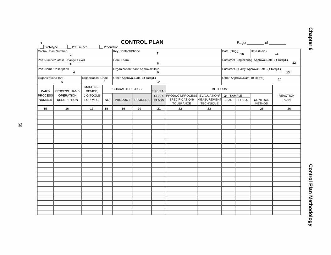
Ch
ap
ter 6
C
on
trol P
lan
Me
tho
do
log
y
50
1
Prototype
Pre-Launch
Production
CONTROL PLAN Page of
Control Plan Number
2 Key Contact/Phone
7 Date (Orig.)
10 Date (Rev.)
11
Part Number/Latest Change Level
3 Core Team
8 Customer Engineering Approval/Date (If Req'd.)
12
Part Name/Description 4
Organization/Plant Approval/Date 9
Customer Quality Approval/Date (If Req'd.) 13
Organization/Plant
5 Organization Code
6 Other Approval/Date (If Req'd.)
14 Other Approval/Date (If Req'd.)
14
PART/
PROCESS
NUMBER
PROCESS NAME/
OPERATION
DESCRIPTION
MACHINE,
DEVICE,
JIG,TOOLS
FOR MFG.
CHARACTERISTICS SPECIAL
METHODS
REACTION
PLAN
NO.
PRODUCT
PROCESS CHAR.
CLASS PRODUCT/PROCESS
SPECIFICATION/
TOLERANCE
EVALUATION/
MEASUREMEN T
TECHNIQUE
24 SAMPLE CONTROL
METHOD SIZE FREQ.
15 16 17 18 19 20 21 22 23 25 26
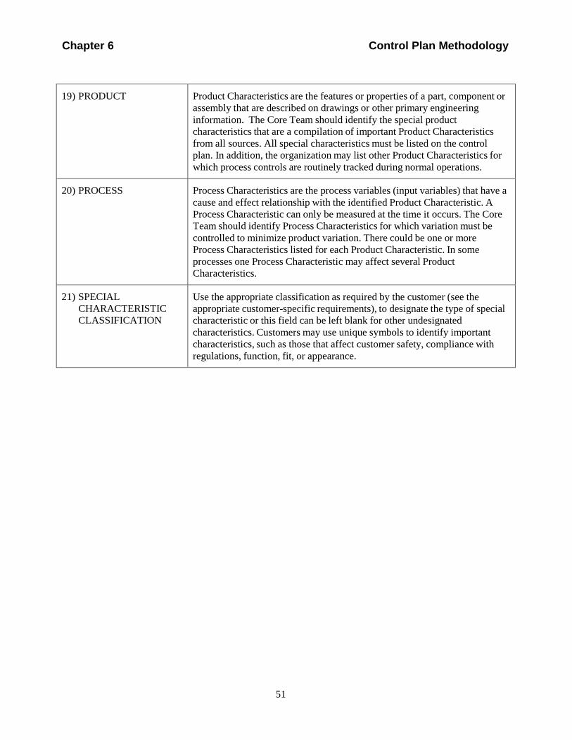
Chapter 6 Control Plan Methodology
19) PRODUCT
Product Characteristics are the features or properties of a part, component or
assembly that are described on drawings or other primary engineering
information. The Core Team should identify the special product
characteristics that are a compilation of important Product Characteristics
from all sources. All special characteristics must be listed on the control
plan. In addition, the organization may list other Product Characteristics for
which process controls are routinely tracked during normal operations.
20) PROCESS
Process Characteristics are the process variables (input variables) that have a
cause and effect relationship with the identified Product Characteristic. A
Process Characteristic can only be measured at the time it occurs. The Core
Team should identify Process Characteristics for which variation must be
controlled to minimize product variation. There could be one or more
Process Characteristics listed for each Product Characteristic. In some
processes one Process Characteristic may affect several Product
Characteristics.
21) SPECIAL
CHARACTERISTIC
CLASSIFICATION
Use the appropriate classification as required by the customer (see the
appropriate customer-specific requirements), to designate the type of special
characteristic or this field can be left blank for other undesignated
characteristics. Customers may use unique symbols to identify important
characteristics, such as those that affect customer safety, compliance with
regulations, function, fit, or appearance.
51
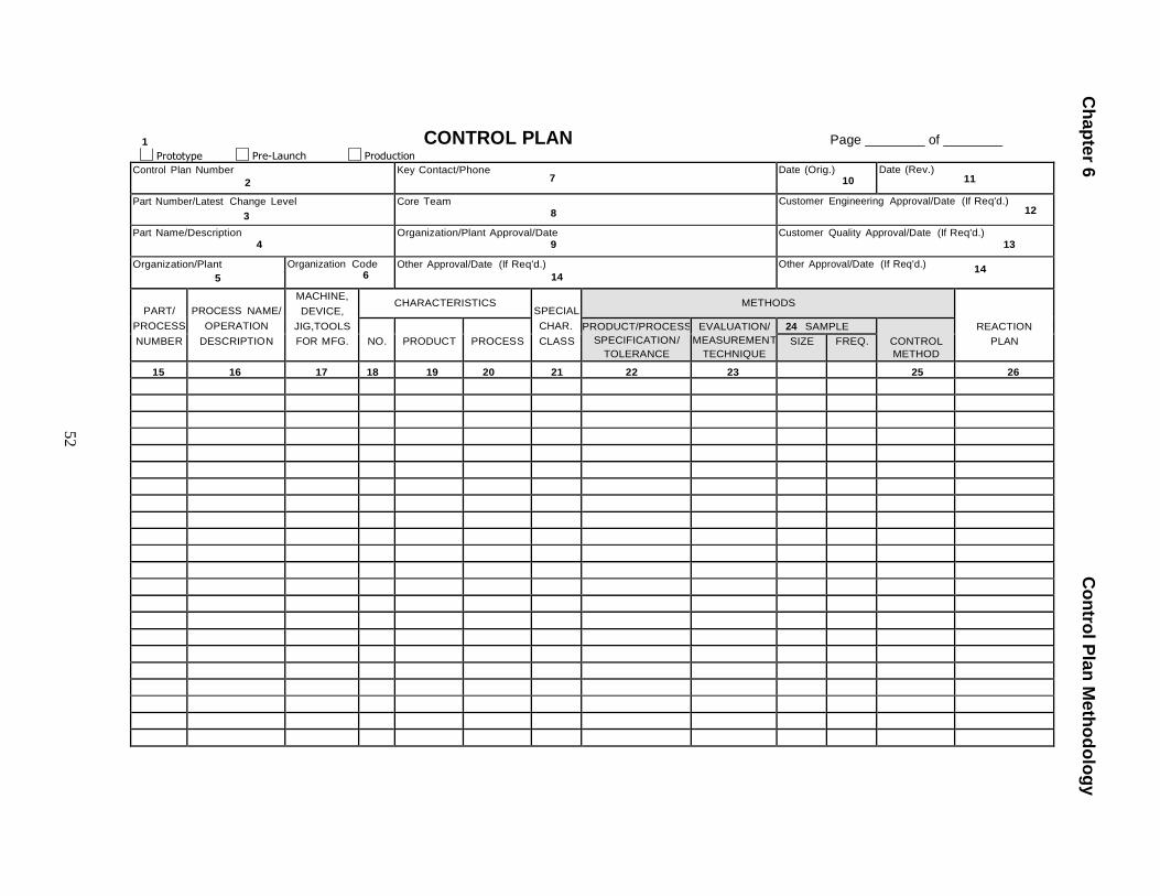
Ch
ap
ter 6
C
on
trol P
lan
Me
tho
do
log
y
52
1
Prototype
Pre-Launch
Production
CONTROL PLAN Page of
Control Plan Number
2 Key Contact/Phone
7 Date (Orig.)
10 Date (Rev.)
11
Part Number/Latest Change Level
3 Core Team
8 Customer Engineering Approval/Date (If Req'd.)
12
Part Name/Description 4
Organization/Plant Approval/Date 9
Customer Quality Approval/Date (If Req'd.) 13
Organization/Plant
5 Organization Code
6 Other Approval/Date (If Req'd.)
14 Other Approval/Date (If Req'd.)
14
PART/
PROCESS
NUMBER
PROCESS NAME/
OPERATION
DESCRIPTION
MACHINE,
DEVICE,
JIG,TOOLS
FOR MFG.
CHARACTERISTICS SPECIAL
CHAR.
CLASS
METHODS
REACTION
PLAN
NO.
PRODUCT
PROCESS PRODUCT/PROCESS
SPECIFICATION/
TOLERANCE
EVALUATION/
MEASUREMEN T
TECHNIQUE
24 SAMPLE CONTROL
METHOD SIZE FREQ.
15 16 17 18 19 20 21 22 23 25 26
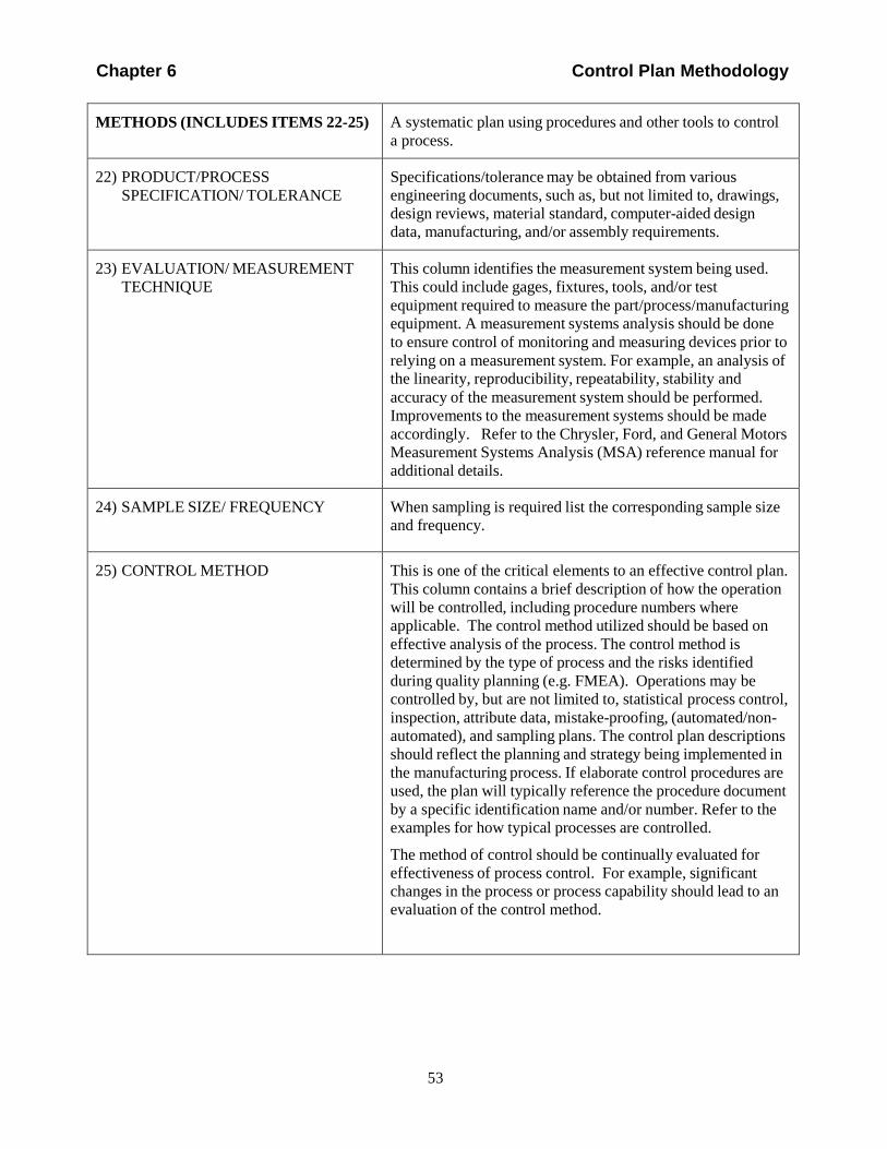
Chapter 6 Control Plan Methodology
METHODS (INCLUDES ITEMS 22-25)
A systematic plan using procedures and other tools to control
a process.
22) PRODUCT/PROCESS
SPECIFICATION/ TOLERANCE
Specifications/tolerance may be obtained from various
engineering documents, such as, but not limited to, drawings,
design reviews, material standard, computer-aided design
data, manufacturing, and/or assembly requirements.
23) EVALUATION/ MEASUREMENT
TECHNIQUE
This column identifies the measurement system being used.
This could include gages, fixtures, tools, and/or test
equipment required to measure the part/process/manufacturing
equipment. A measurement systems analysis should be done
to ensure control of monitoring and measuring devices prior to
relying on a measurement system. For example, an analysis of the linearity, reproducibility, repeatability, stability and
accuracy of the measurement system should be performed.
Improvements to the measurement systems should be made
accordingly. Refer to the Chrysler, Ford, and General Motors
Measurement Systems Analysis (MSA) reference manual for
additional details.
24) SAMPLE SIZE/ FREQUENCY
When sampling is required list the corresponding sample size
and frequency.
25) CONTROL METHOD
This is one of the critical elements to an effective control plan.
This column contains a brief description of how the operation
will be controlled, including procedure numbers where
applicable. The control method utilized should be based on
effective analysis of the process. The control method is
determined by the type of process and the risks identified
during quality planning (e.g. FMEA). Operations may be
controlled by, but are not limited to, statistical process control,
inspection, attribute data, mistake-proofing, (automated/non-
automated), and sampling plans. The control plan descriptions
should reflect the planning and strategy being implemented in
the manufacturing process. If elaborate control procedures are
used, the plan will typically reference the procedure document
by a specific identification name and/or number. Refer to the
examples for how typical processes are controlled.
The method of control should be continually evaluated for
effectiveness of process control. For example, significant
changes in the process or process capability should lead to an
evaluation of the control method.
53
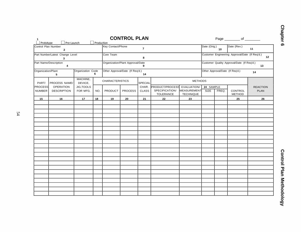
Ch
ap
ter 6
C
on
trol P
lan
Me
tho
do
log
y
54
1
Prototype
Pre-Launch
Production
CONTROL PLAN Page of
Control Plan Number
2 Key Contact/Phone
7 Date (Orig.)
10 Date (Rev.)
11
Part Number/Latest Change Level
3 Core Team
8 Customer Engineering Approval/Date (If Req'd.)
12
Part Name/Description 4
Organization/Plant Approval/Date 9
Customer Quality Approval/Date (If Req'd.) 13
Organization/Plant
5 Organization Code
6 Other Approval/Date (If Req'd.)
14 Other Approval/Date (If Req'd.)
14
PART/
PROCESS
NUMBER
PROCESS NAME/
OPERATION
DESCRIPTION
MACHINE,
DEVICE,
JIG,TOOLS
FOR MFG.
CHARACTERISTICS SPECIAL
CHAR.
CLASS
METHODS
REACTION
PLAN
NO.
PRODUCT
PROCESS PRODUCT/PROCESS
SPECIFICATION/
TOLERANCE
EVALUATION/
MEASUREMEN T
TECHNIQUE
24 SAMPLE CONTROL
METHOD SIZE FREQ.
15 16 17 18 19 20 21 22 23 25 26
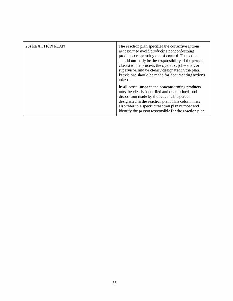
55
26) REACTION PLAN The reaction plan specifies the corrective actions
necessary to avoid producing nonconforming
products or operating out of control. The actions
should normally be the responsibility of the people
closest to the process, the operator, job-setter, or
supervisor, and be clearly designated in the plan.
Provisions should be made for documenting actions
taken.
In all cases, suspect and nonconforming products
must be clearly identified and quarantined, and
disposition made by the responsible person
designated in the reaction plan. This column may
also refer to a specific reaction plan number and
identify the person responsible for the reaction plan.
56
6.2 Process Analysis
Different types of processes present challenges and opportunities for
control and reduction of variation. The process types can be related to their
most common sources of variation or the dominant factors in determining
the quality of the product. There are many effective methods of performing
process analysis. It is up to the organization to determine the best method
to analyze the process. Examples are:
• Fault Tree Analysis
• Design of Experiments
• Cause and Effect (see Appendix B)
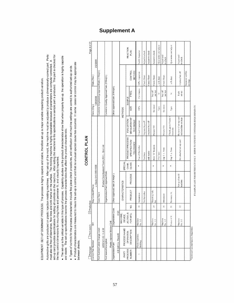
57
Supplement A
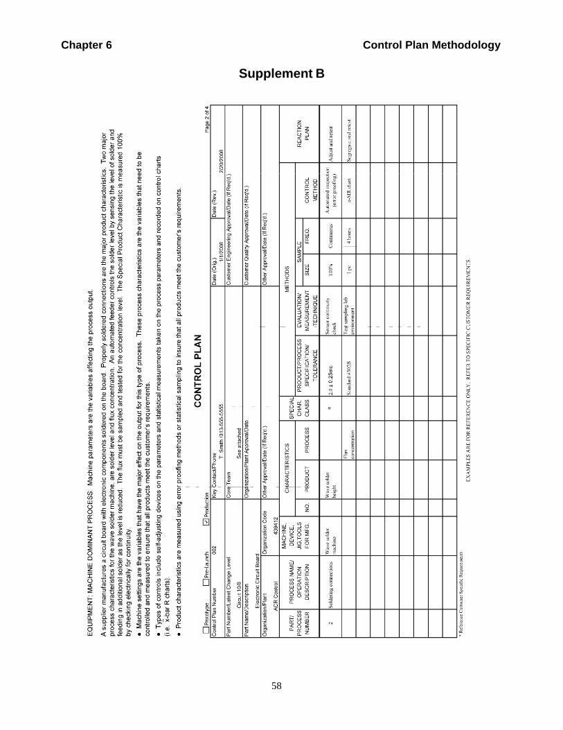
58
Chapter 6 Control Plan Methodology
Company
MotorOnly
FordUse
of
Internal
Supplement B
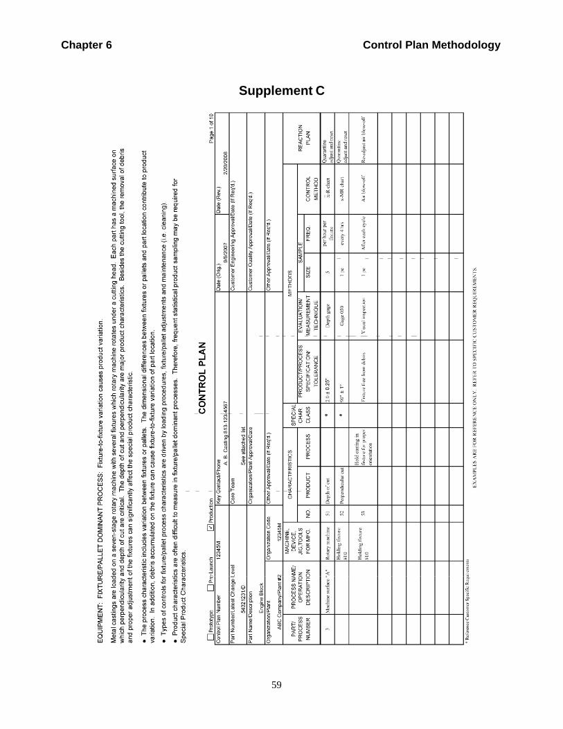
59
Chapter 6 Control Plan Methodology
Compa
MotorOnly
FordUse
of
Internal
Supplement C
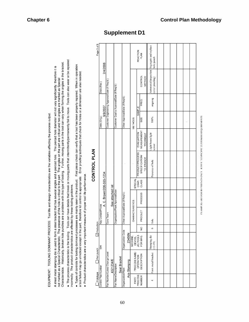
60
Chapter 6 Control Plan Methodology
Supplement D1
Compa
MotorOnly
Use
Ford of
Interna
l
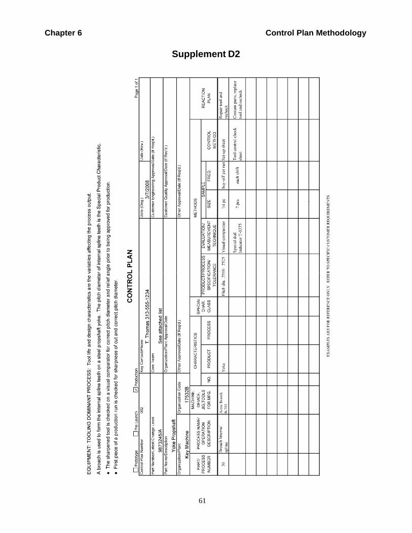
61
Chapter 6 Control Plan Methodology
Supplement D2
Comp
MotorOnly
Use
Ford of
Interna
l
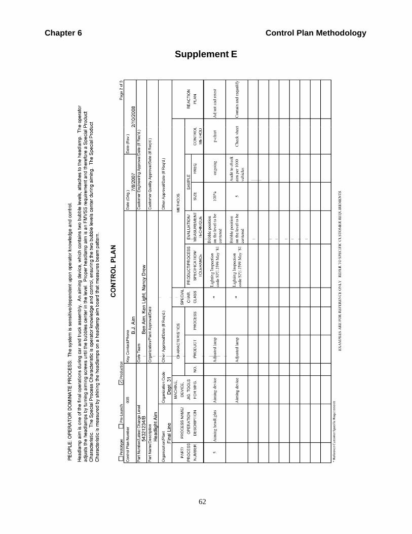
62
Chapter 6 Control Plan Methodology
Supplement E
Compan
y
MotorOnly
FordUse
of
Internal
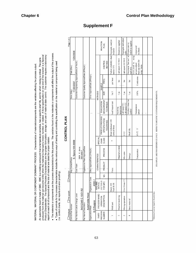
63
Chapter 6 Control Plan Methodology
Supplement F
Compa
MotorOnly
FordUse
of
Internal
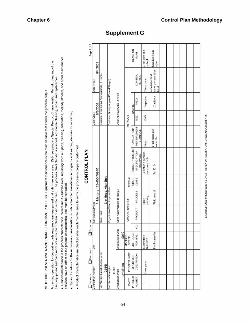
64
Chapter 6 Control Plan Methodology
Supplement G
Compa
MotorOnly
Use
Ford of
Interna
l
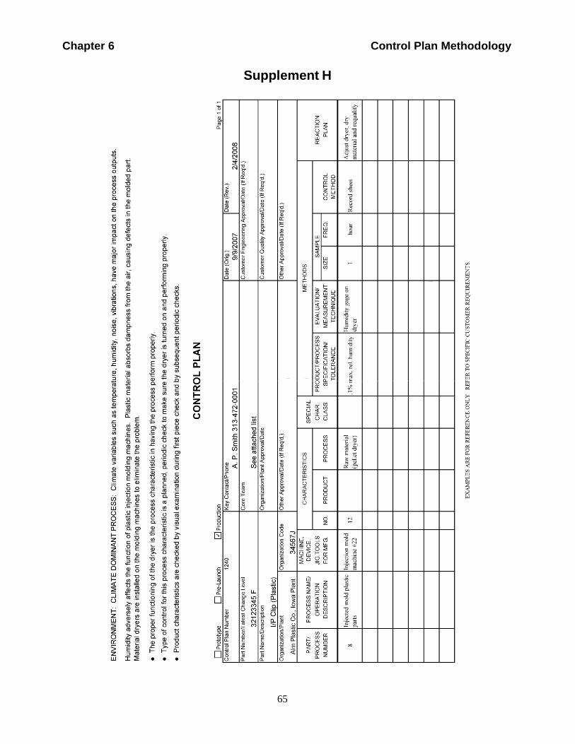
65
Chapter 6 Control Plan Methodology
Supplement H
Compa
MotorOnly
Use
Ford of
Interna
l
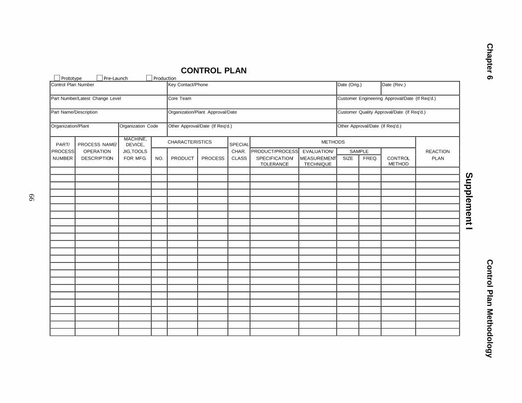
Ch
ap
ter 6
C
on
trol P
lan
Me
tho
do
log
y
Su
pp
lem
en
t I
66
Prototype
Pre-Launch
Production
CONTROL PLAN
Control Plan Number Key Contact/Phone Date (Orig.) Date (Rev.)
Part Number/Latest Change Level Core Team Customer Engineering Approval/Date (If Req'd.)
Part Name/Description Organization/Plant Approval/Date Customer Quality Approval/Date (If Req'd.)
Organization/Plant Organization Code Other Approval/Date (If Req'd.) Other Approval/Date (If Req'd.)
PART/
PROCESS
NUMBER
PROCESS NAME/
OPERATION
DESCRIPTION
MACHINE,
DEVICE,
JIG,TOOLS
FOR MFG.
CHARACTERISTICS
SPECIAL
CHAR.
CLASS
METHODS
REACTION
PLAN
NO.
PRODUCT
PROCESS PRODUCT/PROCESS
SPECIFICATION/
TOLERANCE
EVALUATION/
MEASUREMENT
TECHNIQUE
SAMPLE CONTROL
METHOD SIZE FREQ.
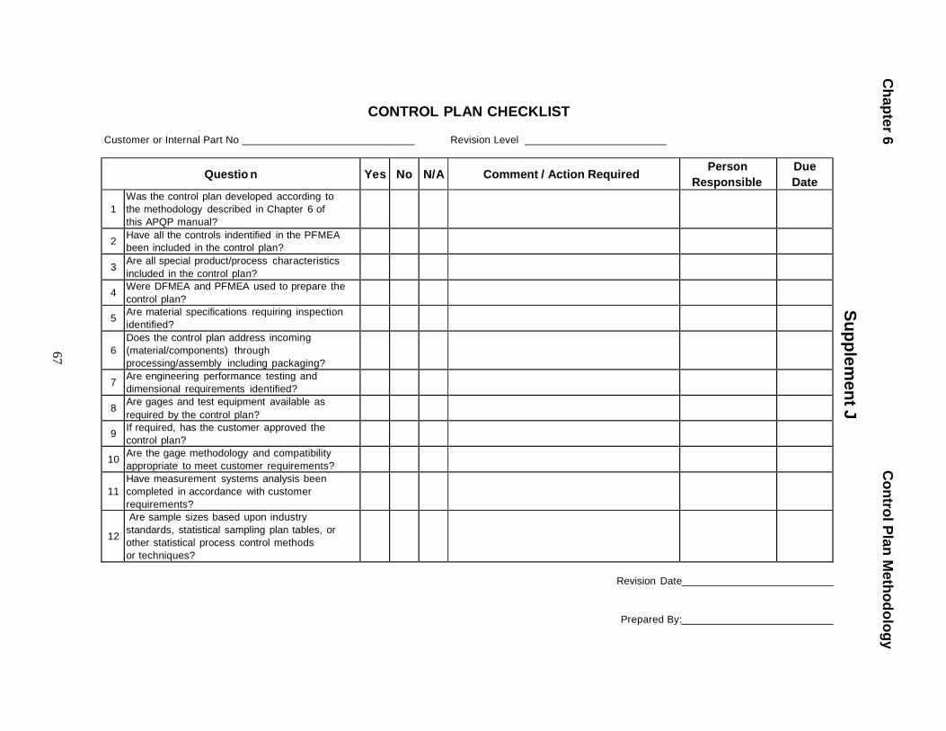
Ch
ap
ter 6
C
on
trol P
lan
Me
tho
do
log
y
Su
pp
lem
en
t J
67
CONTROL PLAN CHECKLIST
Customer or Internal Part No Revision Level
Questio n
Yes
No
N/A
Comment / Action Required Person
Responsible Due
Date
1 Was the control plan developed according to
the methodology described in Chapter 6 of
this APQP manual?
2 Have all the controls indentified in the PFMEA
been included in the control plan?
3 Are all special product/process characteristics
included in the control plan?
4 Were DFMEA and PFMEA used to prepare the
control plan?
5 Are material specifications requiring inspection
identified?
6
Does the control plan address incoming
(material/components) through
processing/assembly including packaging?
7 Are engineering performance testing and
dimensional requirements identified?
8 Are gages and test equipment available as
required by the control plan?
9 If required, has the customer approved the
control plan?
10 Are the gage methodology and compatibility
appropriate to meet customer requirements?
11
Have measurement systems analysis been
completed in accordance with customer
requirements?
12
Are sample sizes based upon industry
standards, statistical sampling plan tables, or
other statistical process control methods
or techniques?
Revision Date
Prepared By:
Chapter 6 Control Plan Methodology
68
Special Characteristics Worksheet
SUPPLEMENT K
The Description/Rationale column includes all special process and product characteristics agreed upon by
the cross functional team. A sequential number (No.) is assigned to each characteristics listed to ensure none
are overlooked by the supplier when the control plan (Part Two) is completed. Develop a rationale for each
special characteristic and add this information to the list for clarification. When considered necessary, a
Supplemental Form (Supplement L) will depict measurement points and coordinates. This form, when used,
will be considered an extension of the control plan.
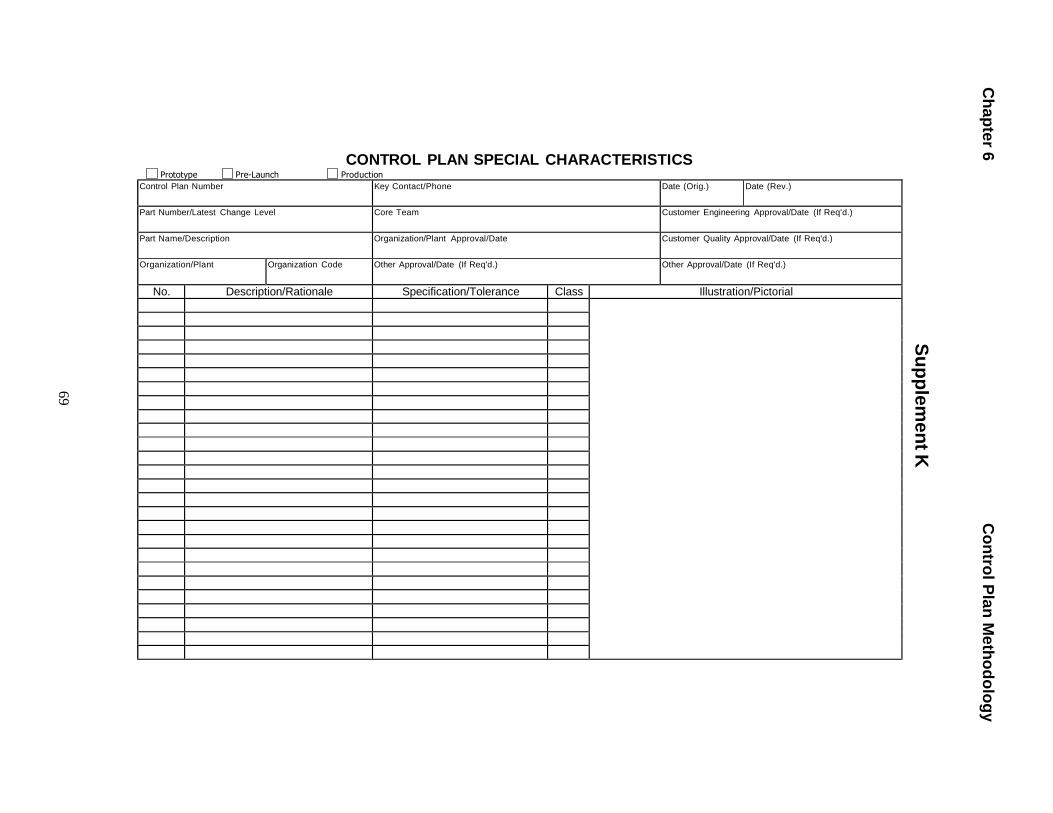
Ch
ap
ter 6
C
on
trol P
lan
Me
tho
do
log
y
Su
pp
lem
en
t K
69
CONTROL PLAN SPECIAL CHARACTERISTICS Prototype Pre-Launch Production
Control Plan Number Key Contact/Phone Date (Orig.) Date (Rev.)
Part Number/Latest Change Level Core Team Customer Engineering Approval/Date (If Req'd.)
Part Name/Description Organization/Plant Approval/Date Customer Quality Approval/Date (If Req'd.)
Organization/Plant Organization Code Other Approval/Date (If Req'd.) Other Approval/Date (If Req'd.)
No. Description/Rationale Specification/Tolerance Class Illustration/Pictorial
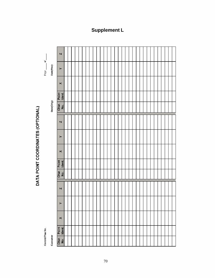
70
Supplement L
71
Appendix A Product Quality Planning Checklists
APPENDIX A PRODUCT QUALITY PLANNING CHECKLISTS
72
Appendix A Product Quality Planning Checklists
Purpose of the Checklists
The following checklists are provided to assist the organization’s product
quality planning team in order to verify that the APQP process is both
complete and accurate. These checklists are not intended to fully define or
represent all elements of the APQP process. The use of the checklists is
one of the last steps of the process and not intended as a "check the box"
activity or exercise to circumvent full application of the APQP process.
In reviewing the questions in the checklist, where "No" is identified as the
appropriate response, the column "Comment/Action Required" is used to
identify the action required to close the gap, including the impact on the
APQP process. The follow up action should include identification of an
individual responsible and schedule. Use the "Person Responsible" and
"Due Date" columns.
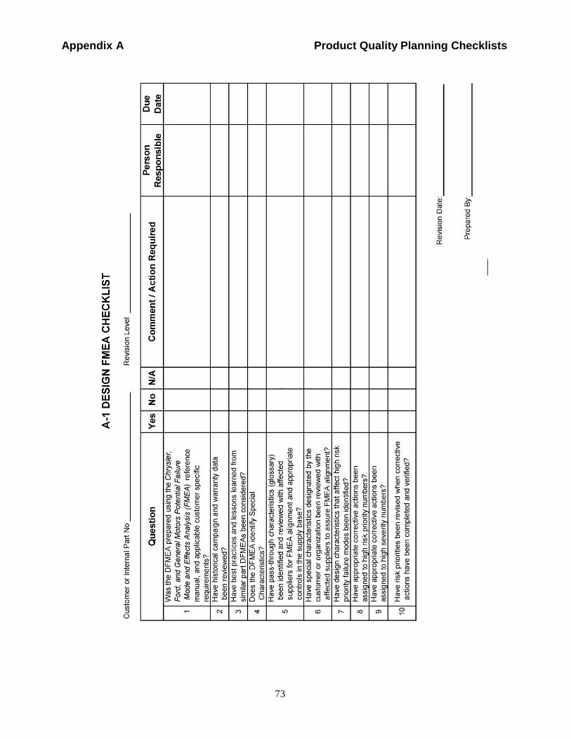
Appendix A Product Quality Planning Checklists
Compa
n
Only
Motor
FordUse
of
Internal
73
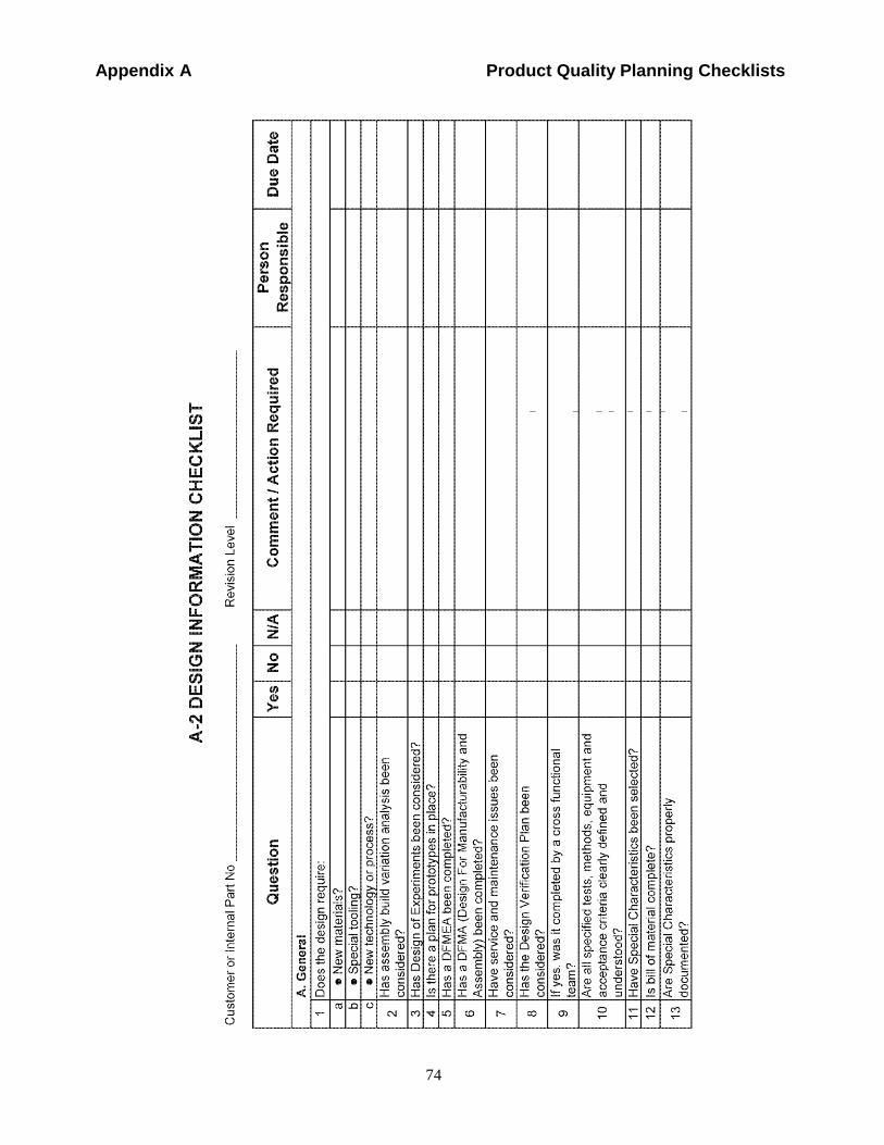
Appendix A Product Quality Planning Checklists
Comp
MotorOnly
FordUse
of
Internal
74
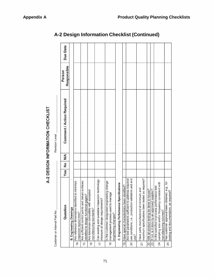
Appendix A Product Quality Planning Checklists
75
Compa
MotorOnly
FordUse
of
Internal
A-2 Design Information Checklist (Continued)
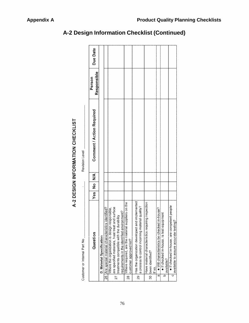
76
Appendix A Product Quality Planning Checklists
A-2 Design Information Checklist (Continued)
FordUse
of
Internal
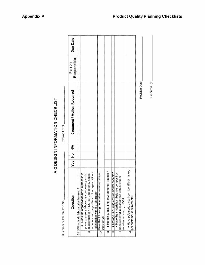
Appendix A Product Quality Planning Checklists
FordUse
of
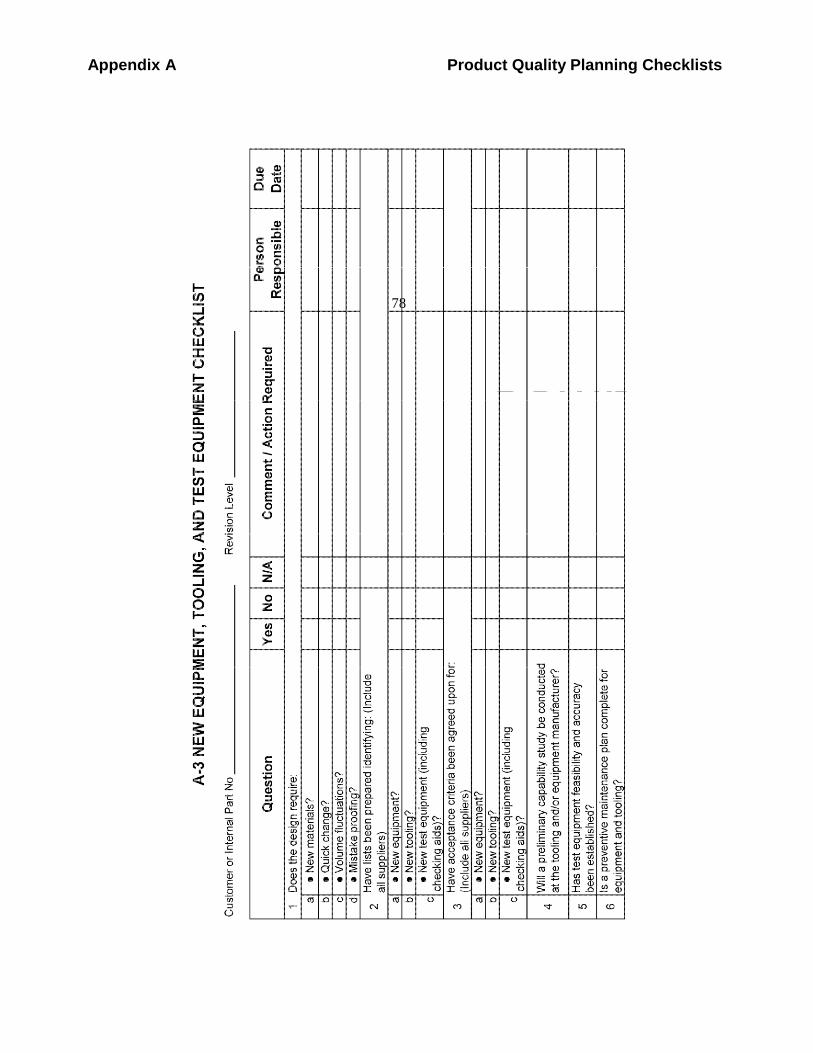
Appendix A Product Quality Planning Checklists
Comp
MotorOnly
Use
Ford of
Interna
l
78
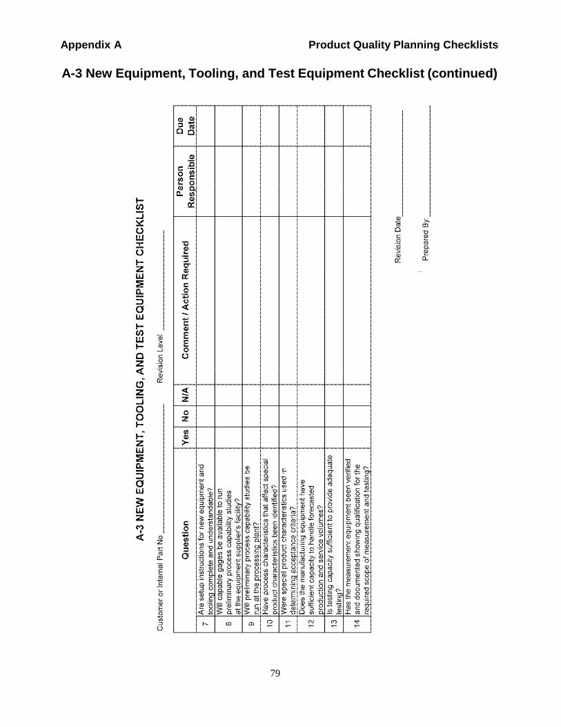
Appendix A Product Quality Planning Checklists
Comp
MotorOnly
Use
Ford of
Interna
l
A-3 New Equipment, Tooling, and Test Equipment Checklist (continued)
79
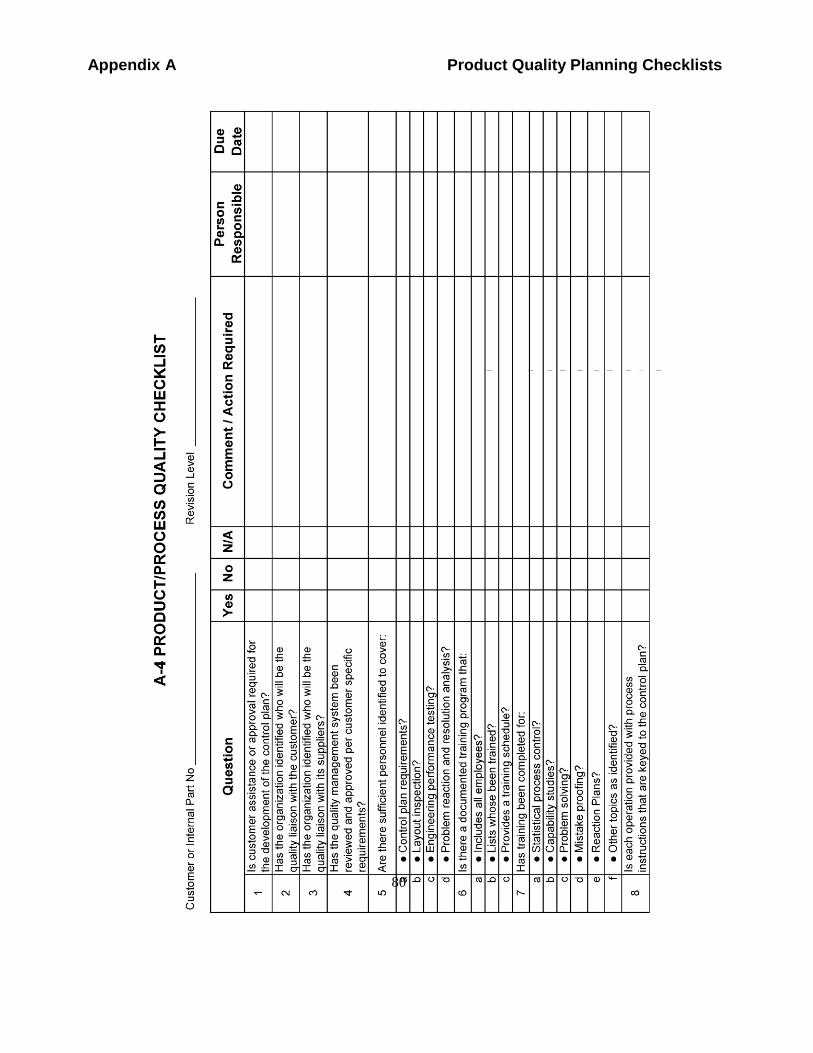
Appendix A Product Quality Planning Checklists
Compa
MotorOnly
FordUse
of
Internal
80
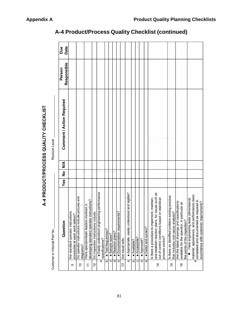
Appendix A Product Quality Planning Checklists
A-4 Product/Process Quality Checklist (continued)
81
Compa
MotorOnly
FordUse
of
Internal
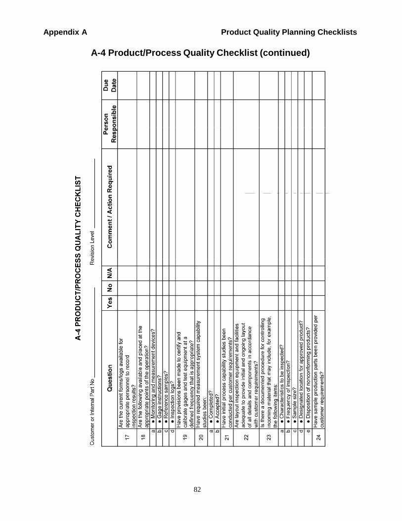
Appendix A Product Quality Planning Checklists
A-4 Product/Process Quality Checklist (continued)
82
Compa
MotorOnly
FordUse
of
Internal
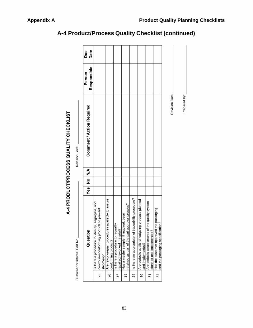
Appendix A Product Quality Planning Checklists
A-4 Product/Process Quality Checklist (continued)
83
Com
MotorOnly
FordUse
of
Internal
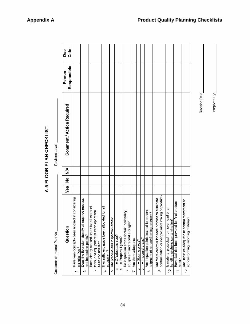
Appendix A Product Quality Planning Checklists
84
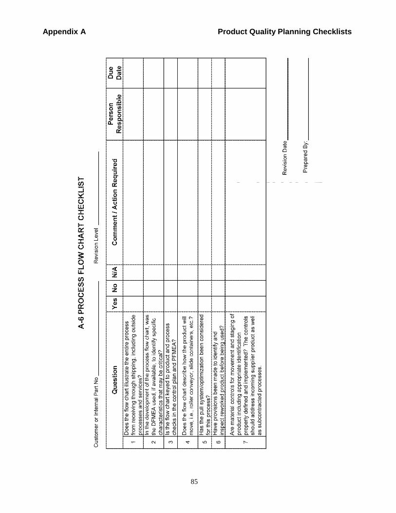
Appendix A Product Quality Planning Checklists
Compa
MotorOnly
FordUse
of
Internal
85
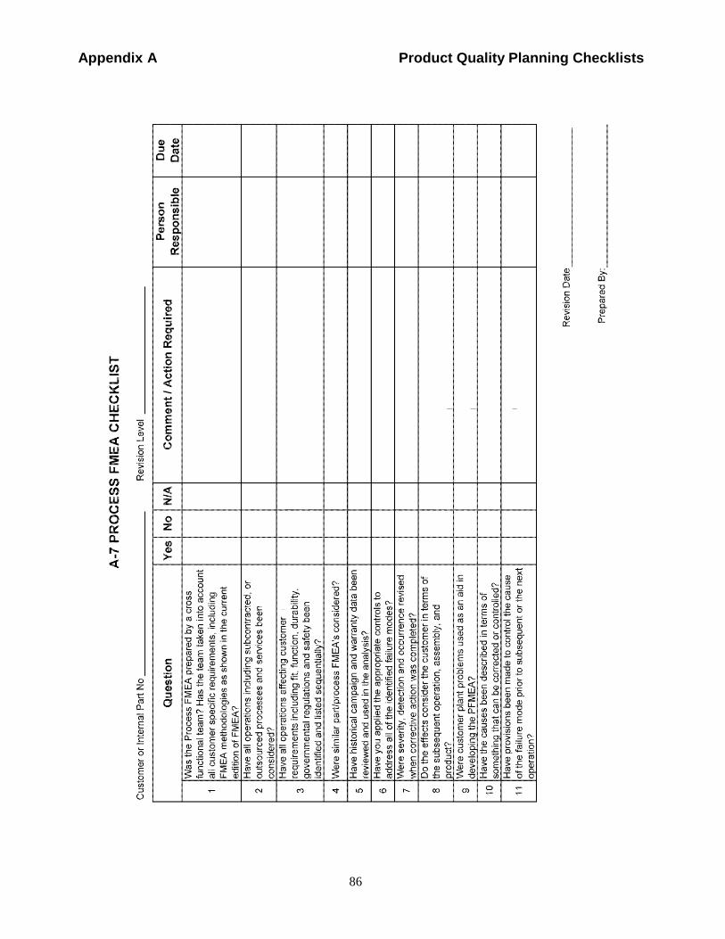
Appendix A Product Quality Planning Checklists
Company
MotorOnly
FordUse
of
Internal
86
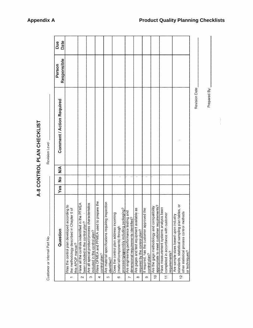
Appendix A Product Quality Planning Checklists
Company
MotorOnly
FordUse
of
Internal
7
Appendix B Analytical Techniques
88
APPENDIX B ANALYTICAL TECHNIQUES
Appendix B Analytical Techniques
89
Assembly Build Variation Analysis
An assembly build variation analysis is an analysis that simulates the
buildup of an assembly and examines tolerance accumulation, statistical
parameters, sensitivity, and "what if" investigation.
Benchmarking
Benchmarking is a systematic approach to identifying standards for
comparison. It provides input to the establishment of measurable
performance targets, as well as ideas for product design and process design.
It can also provide ideas for improving business processes and work
procedures.
Product and process benchmarking should include the identification of
world class or best-in-class based on customer and internal objective
performance measures and research into how this performance was
achieved. Benchmarking should provide a stepping stone for developing
new designs and processes that exceed the capabilities of the benchmark
companies.
Cause and Effect Diagram
The "cause and effect" diagram is an analytical tool to indicate the
relationship between an "effect" and all possible "causes" influencing it.
This is sometimes referred to as fishbone diagram, Ishikawa diagram, or
feather diagram.
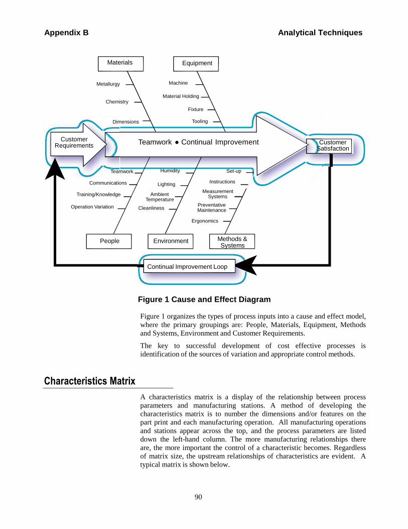
Appendix B Analytical Techniques
90
p
Materials Equipment
Metallurgy
Chemistry
Dimensions
Machine
Material Holding
Fixture
Tooling
Customer
Requirements
Teamwork ● Continual Improvement
Customer Satisfaction
Teamwork
Communications
Training/Knowledge
Operation Variation
Humidity
Lighting
Ambient Temperature
Cleanliness
Set-up
Instructions
Measurement Systems
Preventative Maintenance
Ergonomics
People Environment Methods & Systems
Continual Improvement Loop
Figure 1 Cause and Effect Diagram
Figure 1 organizes the types of process inputs into a cause and effect model,
where the primary groupings are: People, Materials, Equipment, Methods
and Systems, Environment and Customer Requirements.
The key to successful development of cost effective processes is
identification of the sources of variation and appropriate control methods.
Characteristics Matrix
A characteristics matrix is a display of the relationship between process
parameters and manufacturing stations. A method of developing the
characteristics matrix is to number the dimensions and/or features on the
part print and each manufacturing operation. All manufacturing operations
and stations appear across the top, and the process parameters are listed
down the left-hand column. The more manufacturing relationships there
are, the more important the control of a characteristic becomes. Regardless
of matrix size, the upstream relationships of characteristics are evident. A
typical matrix is shown below.
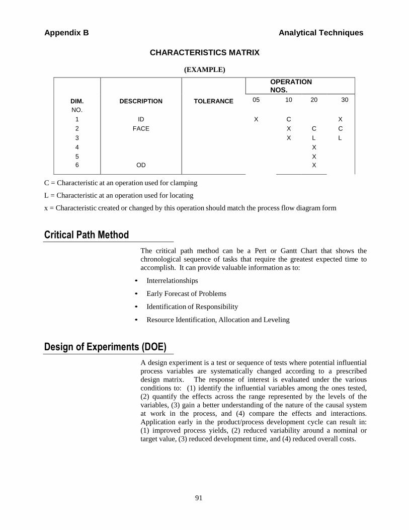
Appendix B Analytical Techniques
91
CHARACTERISTICS MATRIX
(EXAMPLE)
DIM.
NO.
1
2
3
4
5
6
DESCRIPTION
ID
FACE
OD
TOLERANCE
OPERATION NOS.
05
X
10
C
X
X
20
C
L
X
X
X
30
X
C
L
C = Characteristic at an operation used for clamping
L = Characteristic at an operation used for locating
x = Characteristic created or changed by this operation should match the process flow diagram form
Critical Path Method
The critical path method can be a Pert or Gantt Chart that shows the
chronological sequence of tasks that require the greatest expected time to
accomplish. It can provide valuable information as to:
• Interrelationships
• Early Forecast of Problems
• Identification of Responsibility
• Resource Identification, Allocation and Leveling
Design of Experiments (DOE)
A design experiment is a test or sequence of tests where potential influential
process variables are systematically changed according to a prescribed
design matrix. The response of interest is evaluated under the various
conditions to: (1) identify the influential variables among the ones tested,
(2) quantify the effects across the range represented by the levels of the
variables, (3) gain a better understanding of the nature of the causal system
at work in the process, and (4) compare the effects and interactions.
Application early in the product/process development cycle can result in:
(1) improved process yields, (2) reduced variability around a nominal or
target value, (3) reduced development time, and (4) reduced overall costs.
Appendix B Analytical Techniques
92
Design for Manufacturability and Assembly
Design for Manufacturability and Assembly is a Simultaneous Engineering
process designed to optimize the relationship between design function,
manufacturability, and ease of assembly. The enhancement of designs for
assembly and manufacturing is an important step. Plant representatives
should be consulted early in the design process to review components or
systems and provide input on specific assembly and manufacturing
requirements. Specific dimensional tolerances should be determined based
on the like process. This will assist in identifying the equipment required
and any process changes necessary.
Design Verification Plan and Report (DVP&R)
The Design Verification Plan and Report (DVP&R) is a method to plan and
document testing activity through each phase of product/process
development from inception to ongoing refinement. An effective DVP&R
provides a concise working document that aids engineering personnel in the
following areas:
• Facilitates the development of a logical testing sequence by requiring the
responsible areas to thoroughly plan the tests needed to assure that the
component or system meets all engineering requirements.
• Assures product reliability meets customer-driven objectives.
• Highlights situations where customer timing requires an accelerated test
plan.
• Serves as a working tool for responsible area(s) by:
Summarizing functional, durability, and reliability testing
requirements and results in one document for ease of reference.
Providing the ability to easily prepare test status and progress
reports for design reviews.
Detailed instructions can be obtained from the appropriate Chrysler and
Ford Quality or Engineering areas.
Mistake Proofing/Error- Proofing
Mistake proofing is a technique to identify errors after they occur. Mistake
proofing should be used as a technique to control repetitive tasks or actions
and prevent non-conformances from being passed on to the subsequent
operation and ultimately the customer. Error-proofing is a technique used
to identify potential process errors and either design them out of the product
Appendix B Analytical Techniques
93
or process, or eliminate the possibility that the error could produce a non-
conformance.
Process Flow Charting
Process flow charting is a visual approach to describing and developing
sequential or related work activities. It provides both a means of
communication and analysis for planning, development activities, and
manufacturing processes.
Since one goal of quality assurance is to eliminate non-conformities and
improve the efficiency of manufacturing and assembly processes, advanced
product quality plans should include illustrations of the controls and
resources involved. These process flow charts should be used to identify
improvements and to locate significant or critical product and process
characteristics that will be addressed in control plans to be developed later.
Quality Function Deployment (QFD)
QFD is a systematic procedure for translating customer requirements into
technical and operational terms, displaying and documenting the translated
information in matrix form. QFD focuses on the most important items and
provides the mechanism to target selected areas to enhance competitive
advantages.
Depending upon the specific product, the technique of QFD may be used as
a structure for the quality planning process. In particular, QFD Phase I -
Product Planning translates customer requirements into counterpart control
characteristics or design requirements. QFD provides a means of
converting general customer requirements into specified final product and
process control characteristics.
A. ASPECTS OF QFD
The two dimensions of QFD are:
• Quality Deployment: Translation of Customer Requirements into Product
Design Requirements.
• Function Deployment: Translation of Design Requirements into
appropriate Part, Process and Production Requirements.
B. BENEFITS OF QFD
• Increases the assurance of meeting the customer requirements.
• Reduces number of changes due to increased engineering understanding
of customer requirements.
• Identifies potentially conflicting design requirements.
Appendix B Analytical Techniques
94
• Focuses various company activities on customer-oriented objectives.
• Reduces product development cycle time.
• Reduces costs of engineering, manufacturing, and service.
• Improves quality of product and services. 1
1 Appendix B developed based on the following references:
Duncan, A. J. (1974). Quality Control and Industrial Statistics (4th Ed.). Homewood, IL: Richard D. Irwin, Inc.
Feigenbaum, A. V. (1991). Total Quality Control (3rd Ed. Revised). New York: McGraw - Hill.
Grant, E. L. & Leavenworth, R. S. (1980). Statistical Quality Control, New York: McGraw - Hill.
Ishikawa, K. (1971). Guide to Quality Control, White Plains, NY: Asian Productivity Organization.
Juran, J. M. (1988). Juran's Quality Control Handbook, New York: McGraw - Hill.
Kane, V. E. (1989). Defect Prevention: Use of Simple Statistical Tools, New York: Marcel Dekker, Inc.
Shewhart, W. A. (1931). Economic Control of Quality of Manufactured Product, New York: D. Van Nostrand Company.
Western Electric Company (1956). Statistical Quality Control Handbook. Indianapolis: Author
.
95
Appendix C Reference Material
APPENDIX C REFERENCE MATERIAL
96
Appendix C Reference Material
The following manuals can be obtained from AIAG at www.aiag.org.
Measurement Systems Analysis (MSA) Reference Manual
This is a reference manual that describes common methods of evaluating measurement system variation and
gives general guidance in the application of techniques.
Potential Failure Mode and Effects Analysis (FMEA) Reference Manual
This is a reference manual that potential Failure Mode and Effects Analysis (FMEA) and gives general
guidance in the application of techniques.
Production Part Approval Process (PPAP)
This requirements document covers generic requirements for production part approval for all production and
service commodities.
Statistical Process Control (SPC) Reference Manual
This is a reference manual that provides a unified reference for statistical process control and gives general
guidance in the application of techniques.
97
Appendix D Team Feasibility Commitment
APPENDIX D TEAM FEASIBILITY COMMITMENT
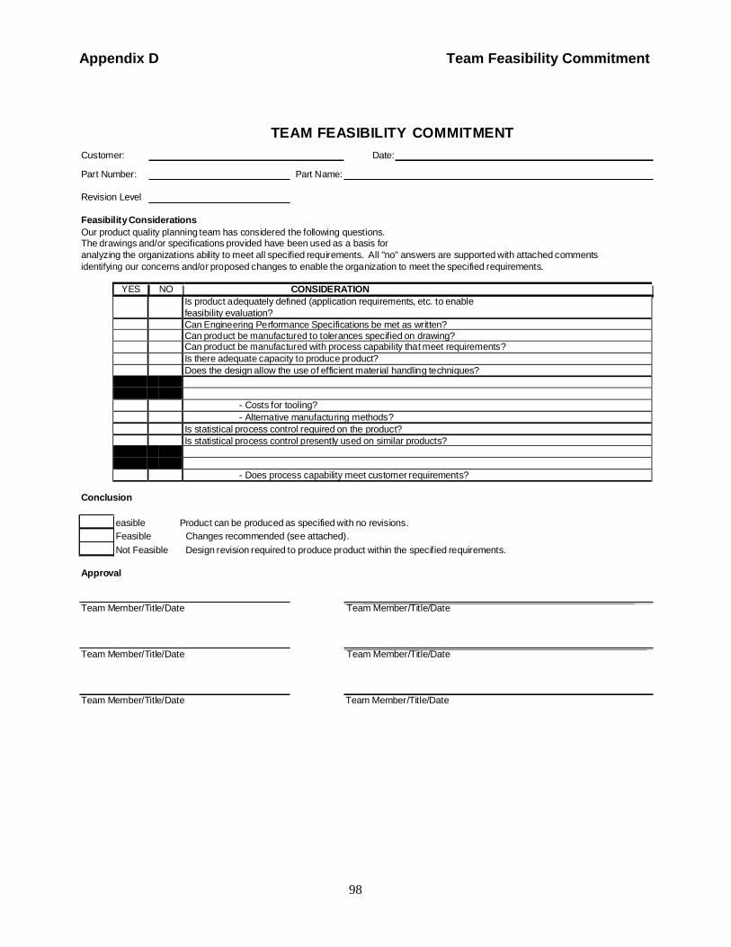
98
Appendix D Team Feasibility Commitment
TEAM FEASIBILITY COMMITMENT
Customer: Date:
Part Number: Part Name:
Revision Level
Feasibility Considerations
Our product quality planning team has considered the following questions. The drawings and/or specifications provided have been used as a basis for
analyzing the organizations ability to meet all specified requirements. All "no" answers are supported with attached comments
identifying our concerns and/or proposed changes to enable the organization to meet the specified requirements.
YES NO CONSIDERATION
Is product adequately defined (application requirements, etc. to enable
feasibility evaluation?
Can Engineering Performance Specifications be met as written? Can product be manufactured to tolerances specified on drawing? Can product be manufactured with process capability that meet requirements?
Is there adequate capacity to produce product?
Does the design allow the use of efficient material handling techniques?
- Costs for tooling?
- Alternative manufacturing methods?
Is statistical process control required on the product?
Is statistical process control presently used on similar products?
- Does process capability meet customer requirements?
Conclusion
easible Product can be produced as specified with no revisions.
Feasible Changes recommended (see attached).
Not Feasible Design revision required to produce product within the specified requirements.
Approval
Team Member/Title/Date Team Member/Title/Date
Team Member/Title/Date Team Member/Title/Date
Team Member/Title/Date Team Member/Title/Date
99
Appendix E Product Quality Planning Summary and Approvals
APPENDIX E PRODUCT QUALITY PLANNING SUMMARY
AND APPROVALS
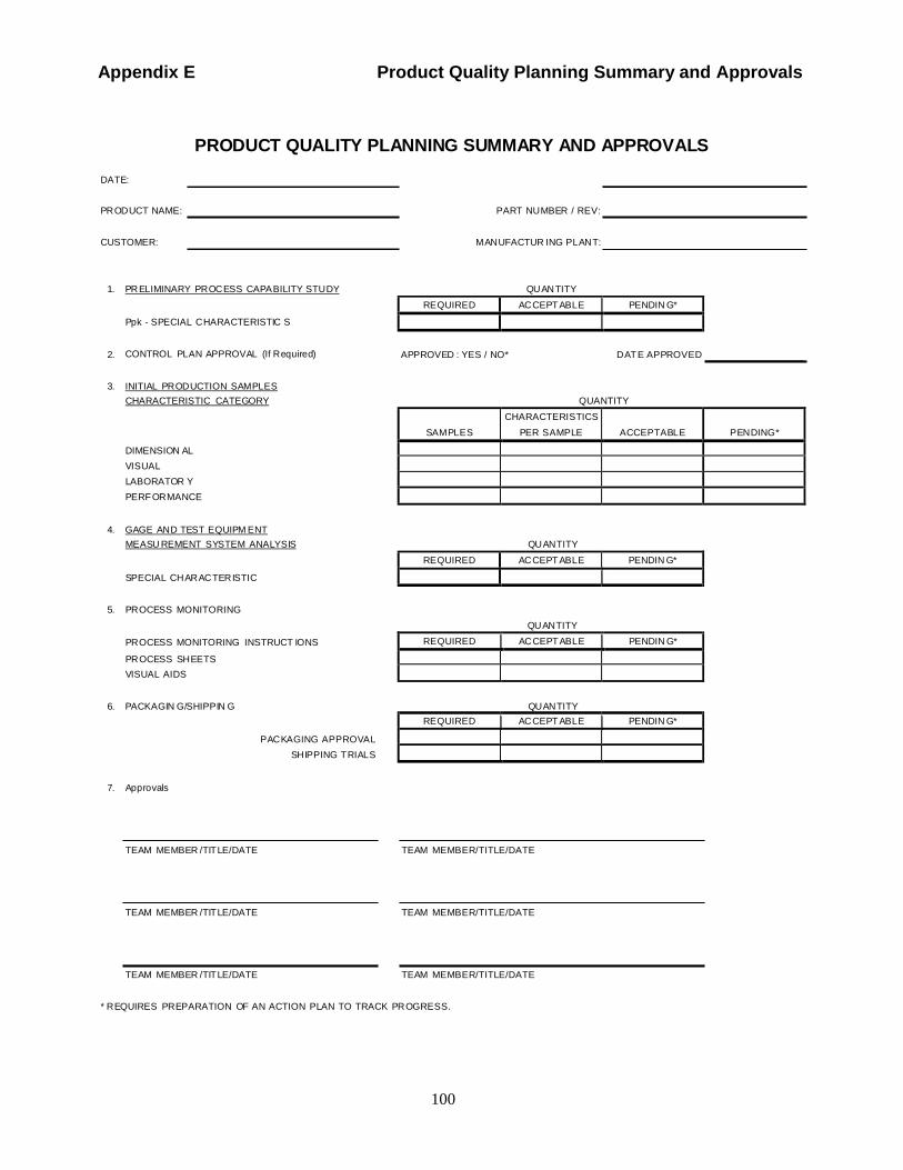
100
Appendix E Product Quality Planning Summary and Approvals
REQUIRED AC CEPT ABLE PENDIN G*
SAM PLES
CHARACTERISTICS
PER SAMPLE
ACCEPTABLE
PEN DING*
REQUIRED AC CEPT ABLE PENDIN G*
REQUIRED AC CEPT ABLE PENDIN G*
REQUIRED AC CEPT ABLE PENDIN G*
PRODUCT QUALITY PLANNING SUMMARY AND APPROVALS
DATE:
PR OD UCT NAME: PART NU MBER / REV:
CUSTOMER: M AN UFACTUR ING PLAN T:
1. PR EL IMINARY PR OC ESS CAPA BILITY STU DY QU AN TITY
Ppk - SPECIAL C HARACTERISTIC S
2. CONTROL PLAN APPROVAL (If R equired) APPROVED : YES / NO* D AT E APPROVED
3. INITIAL PR OD UCTION SAM PLES
CHARACTERISTIC CATEGORY QUANTITY
DIMENSION AL
VISUAL
LABORATOR Y
PERF OR MANCE
4. GAGE AN D TEST EQUIPM ENT
MEASU REMENT SYSTEM ANALYSIS QU AN TITY
SPECIAL CH AR AC TER ISTIC
5. PR OCESS MONITORING
PR OCESS MONITORING INSTRUCT IONS
PR OCESS SH EETS
VISUAL AIDS
QU AN TITY
6. PACKAGIN G/SHIPPIN G QU AN TITY
PAC KAGING APPROVAL
SH IPPING T RIALS
7. Approvals
TEAM MEMBER /TIT LE/DATE TEAM MEMBER/TITLE/DATE
TEAM MEMBER /TIT LE/DATE TEAM MEMBER/TITLE/DATE
TEAM MEMBER /TIT LE/DATE TEAM MEMBER/TITLE/DATE
* R EQUIRES PR EPARATION OF AN ACTION PLAN TO TRACK PR OGRESS.
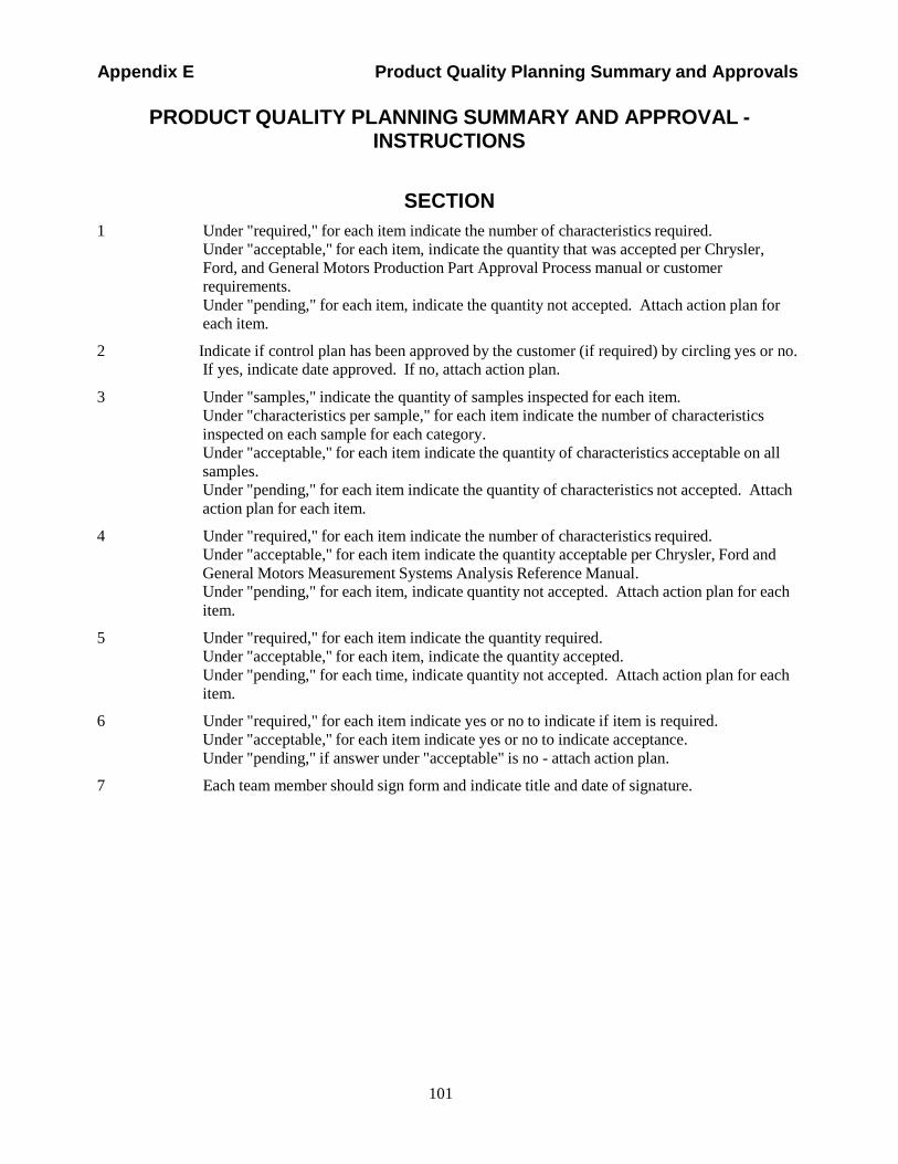
101
Appendix E Product Quality Planning Summary and Approvals
PRODUCT QUALITY PLANNING SUMMARY AND APPROVAL - INSTRUCTIONS
SECTION
1 Under "required," for each item indicate the number of characteristics required.
Under "acceptable," for each item, indicate the quantity that was accepted per Chrysler,
Ford, and General Motors Production Part Approval Process manual or customer
requirements.
Under "pending," for each item, indicate the quantity not accepted. Attach action plan for
each item.
2 Indicate if control plan has been approved by the customer (if required) by circling yes or no. If yes, indicate date approved. If no, attach action plan.
3 Under "samples," indicate the quantity of samples inspected for each item.
Under "characteristics per sample," for each item indicate the number of characteristics
inspected on each sample for each category.
Under "acceptable," for each item indicate the quantity of characteristics acceptable on all
samples.
Under "pending," for each item indicate the quantity of characteristics not accepted. Attach
action plan for each item.
4 Under "required," for each item indicate the number of characteristics required.
Under "acceptable," for each item indicate the quantity acceptable per Chrysler, Ford and
General Motors Measurement Systems Analysis Reference Manual. Under "pending," for each item, indicate quantity not accepted. Attach action plan for each
item.
5 Under "required," for each item indicate the quantity required.
Under "acceptable," for each item, indicate the quantity accepted.
Under "pending," for each time, indicate quantity not accepted. Attach action plan for each
item.
6 Under "required," for each item indicate yes or no to indicate if item is required.
Under "acceptable," for each item indicate yes or no to indicate acceptance.
Under "pending," if answer under "acceptable" is no - attach action plan.
7 Each team member should sign form and indicate title and date of signature.

102
Appendix F Glossary
APPENDIX F GLOSSARY
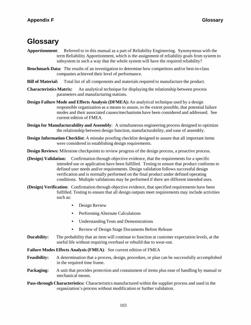
103
Appendix F Glossary
Glossary
Apportionment: Referred to in this manual as a part of Reliability Engineering. Synonymous with the
term Reliability Apportionment, which is the assignment of reliability goals from system to
subsystem in such a way that the whole system will have the required reliability?
Benchmark Data: The results of an investigation to determine how competitors and/or best-in-class
companies achieved their level of performance.
Bill of Material: Total list of all components and materials required to manufacture the product.
Characteristics Matrix: An analytical technique for displaying the relationship between process
parameters and manufacturing stations.
Design Failure Mode and Effects Analysis (DFMEA): An analytical technique used by a design
responsible organization as a means to assure, to the extent possible, that potential failure
modes and their associated causes/mechanisms have been considered and addressed. See
current edition of FMEA.
Design for Manufacturability and Assembly: A simultaneous engineering process designed to optimize
the relationship between design function, manufacturability, and ease of assembly.
Design Information Checklist: A mistake proofing checklist designed to assure that all important items
were considered in establishing design requirements.
Design Reviews: Milestone checkpoints to review progress of the design process, a proactive process.
(Design) Validation: Confirmation through objective evidence, that the requirements for a specific
intended use or application have been fulfilled. Testing to ensure that product conforms to
defined user needs and/or requirements. Design validation follows successful design
verification and is normally performed on the final product under defined operating
conditions. Multiple validations may be performed if there are different intended uses.
(Design) Verification: Confirmation through objective evidence, that specified requirements have been
fulfilled. Testing to ensure that all design outputs meet requirements may include activities
such as:
• Design Review
• Performing Alternate Calculations
• Understanding Tests and Demonstrations
• Review of Design Stage Documents Before Release
Durability: The probability that an item will continue to function at customer expectation levels, at the
useful life without requiring overhaul or rebuild due to wear-out.
Failure Modes Effects Analysis (FMEA): See current edition of FMEA
Feasibility: A determination that a process, design, procedure, or plan can be successfully accomplished
in the required time frame.
Packaging: A unit that provides protection and containment of items plus ease of handling by manual or
mechanical means.
Pass-through Characteristics: Characteristics manufactured within the supplier process and used in the
organization’s process without modification or further validation.
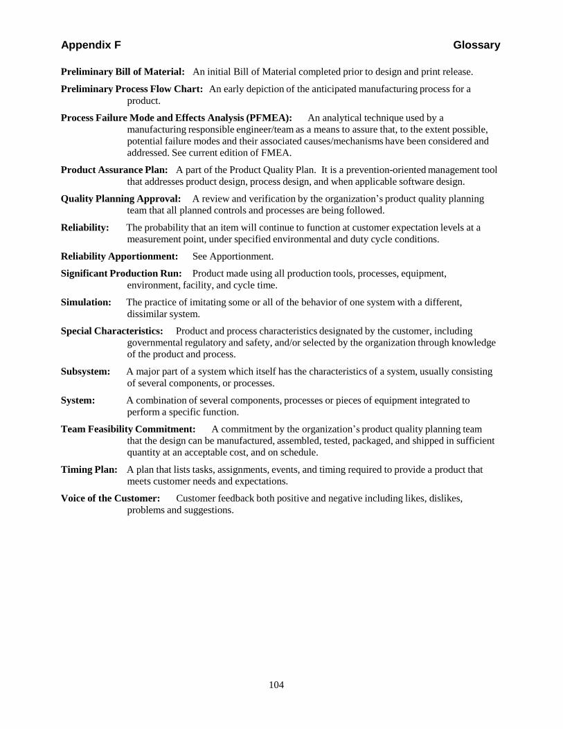
104
Appendix F Glossary
Preliminary Bill of Material: An initial Bill of Material completed prior to design and print release.
Preliminary Process Flow Chart: An early depiction of the anticipated manufacturing process for a
product.
Process Failure Mode and Effects Analysis (PFMEA): An analytical technique used by a
manufacturing responsible engineer/team as a means to assure that, to the extent possible,
potential failure modes and their associated causes/mechanisms have been considered and
addressed. See current edition of FMEA.
Product Assurance Plan: A part of the Product Quality Plan. It is a prevention-oriented management tool
that addresses product design, process design, and when applicable software design.
Quality Planning Approval: A review and verification by the organization’s product quality planning
team that all planned controls and processes are being followed.
Reliability: The probability that an item will continue to function at customer expectation levels at a
measurement point, under specified environmental and duty cycle conditions.
Reliability Apportionment: See Apportionment.
Significant Production Run: Product made using all production tools, processes, equipment,
environment, facility, and cycle time.
Simulation: The practice of imitating some or all of the behavior of one system with a different,
dissimilar system.
Special Characteristics: Product and process characteristics designated by the customer, including
governmental regulatory and safety, and/or selected by the organization through knowledge
of the product and process.
Subsystem: A major part of a system which itself has the characteristics of a system, usually consisting
of several components, or processes.
System: A combination of several components, processes or pieces of equipment integrated to
perform a specific function.
Team Feasibility Commitment: A commitment by the organization’s product quality planning team
that the design can be manufactured, assembled, tested, packaged, and shipped in sufficient
quantity at an acceptable cost, and on schedule.
Timing Plan: A plan that lists tasks, assignments, events, and timing required to provide a product that
meets customer needs and expectations.
Voice of the Customer: Customer feedback both positive and negative including likes, dislikes,
problems and suggestions.
105
Appendix G Index
APPENDIX G INDEX
106
Appendix G Index
Index
A
assembly build variation ......................................19, 89
B
benchmarking.......................................................11, 89
bill of material .............................. 8, 9, 12, 17, 103, 104
business plan/marketing strategy .................................9
C
cause and effect diagram ......................................89, 90
characteristics matrix ..... 24, 25, 27, 28, 33, 90, 91, 103
concern resolution ........................................................5
control planiii, 1, 2, 4, 17, 20, 21, 25, 26, 27, 28, 29, 32,
33, 34, 35, 36, 39, 43, 45, 47, 49, 53, 68, 93, 101 critical
path method................................................5, 91
customer inputs ......................................................9, 12
customer satisfaction...................... 3, 12, 38, 39, 40, 45
customers ............................................. 1, 2, 3, 9, 11, 19 Customers ..................................................................51
D
define the scope........................................................2, 3
delivery ..........................................................38, 39, 40
Design Failure Mode and Effects Analysis (DFMEA) ..................................................... 16, 17, 18, 25, 103
design for manufacturability and assembly...16, 17, 18, 19, 25, 92, 103
design goals............................................ 8, 9, 12, 13, 17
design information checklist ..............................22, 103
design of experiments ....................................19, 56, 91
design responsible ................................................2, 103
design reviews.......... 16, 17, 19, 21, 25, 45, 53, 92, 103
design verification............................ 16, 17, 19, 25, 103
design verification plan and report.......................19, 92
drawing and specification changes...........16, 17, 21, 25
durability .................................... 12, 13, 20, 21, 92, 103
E
engineering drawings ......................... 16, 17, 20, 25, 28
engineering specifications ..............................16, 17, 25
F
facilities requirements ..............................16, 18, 21, 25
Failure Mode and Effects Analysis (FMEA) .......13, 18
feasibility ................... 2, 4, 16, 18, 20, 22, 25, 103, 104
floor plan ............................................ 24, 25, 26, 28, 33
G
gages/testing equipment requirements .....16, 18, 22, 25
H
historical warranty and quality information........... 9, 10
M
management support8, 9, 14, 16, 18, 24, 25, 29, 32, 33, 35, 39
manufacturing only...................................................... 2
market research...................................................... 9, 10
marketing strategy ..................................................... 11
material specifications ....................... 16, 17, 21, 25, 28
measurement systems analysis plan......... 24, 25, 28, 33
measurement systems evaluation................... 32, 33, 39
mistake proofing ................................................ 92, 103
N
new equipment, tooling and facilities requirements . 16,
18, 25
O
organize the team......................................................... 3
P
packaging specification ............................................. 26
packaging standards........................... 24, 25, 26, 28, 33
plans relative to the timing chart ................................. 5
pre-launch control plan ...................... 24, 25, 27, 33, 35
preliminary bill of material .................. 8, 9, 12, 17, 104
preliminary listing of special product and process 9, 17
preliminary process capability plan ........................... 29
preliminary process capability study 24, 25, 29, 32, 33,
34, 39
preliminary process flow chart ............ 8, 9, 13, 17, 104
process capability ...... 24, 25, 29, 32, 33, 34, 39, 40, 53
Process Failure Mode and Effects Analysis (PFMEA)
..................................................... 25, 27, 33, 45, 104
process flow chart . 8, 13, 24, 25, 26, 28, 33, 36, 49, 93,
104
process instructions............................ 24, 25, 28, 33, 36
product assurance plan................... 8, 9, 13, 17, 21, 104
product quality planning cycle...................... viii, 1, 3, 5 product quality planning summary .......................... 101
product quality sign-off ............................................. 35
product quality timing plan.......................................... 5
product reliability studies ...................................... 9, 12
product/process assumptions ........................... 9, 12, 13
product/process benchmark data............................ 9, 11
product/process quality checklist............................... 26
product/process quality system review .... 24, 25, 26, 33
production part approval...... 29, 32, 33, 34, 35, 39, 101
production validation testing ............. 32, 33, 34, 35, 39
prototype........................................ 4, 16, 17, 20, 27, 47
107
Appendix G Index
prototype build - control plan.....................................25
Q
quality function deployment ................................10, 93
quality planning ..................................................... iii, 1
quality planning sign-off ................................32, 34, 39
R
reduced variation..................................................38, 39
reliability goals.............................................12, 13, 103
S
service ............ 1, 2, 3, 11, 13, 17, 19, 20, 38, 39, 40, 94
significant production run ................ 32, 33, 34, 39, 104
similar part FMEA .....................................................13
simulation...........................................................19, 104
simultaneous engineering..................... 4, 5, 18, 92, 103
special product and process characteristics... 13, 16, 18,
20, 21, 25
T
team experience ..................................................... 9, 10
team feasibility commitment ..................................... 22
team-to-team ................................................................ 4
testing equipment requirements ..................... 18, 22, 25
timing chart.................................. 5, 6, 8, 21, 24, 32, 38
training......................................................................... 4
V
validation ....................... 1, 2, 6, 19, 32, 34, 35, 39, 103
variation ......... 18, 19, 26, 38, 39, 43, 45, 51, 56, 89, 90
voice of the customer........................... 9, 10, 12, 17, 20
W
warranty ..................................................... 9, 10, 12, 40
-

Appendix G Index
108