advanced structural analysis prof. devdas menon …nptel.ac.in/reviewed_pdfs/105106050/lec28.pdf ·...
TRANSCRIPT

Advanced Structural Analysis
Prof. Devdas Menon
Department of Civil Engineering
Indian Institute of Technology, Madras
Module - 5.2
Lecture - 28
Matrix Analysis of Beams and Grids
(Refer Slide Time: 00:23)
(Refer Slide Time: 00:30)
Good morning. This is lecture 28, we are continuing with module 5 matrix analysis of
beams and grids. We are reviewing the conventional stiffness method. If you recall, in
the last class we actually solved 1 problem, this is covered in the chapter on beams and
grids in the book on advanced structural analysis.
(Refer Slide Time: 00:38)
(Refer Slide Time: 00:42)
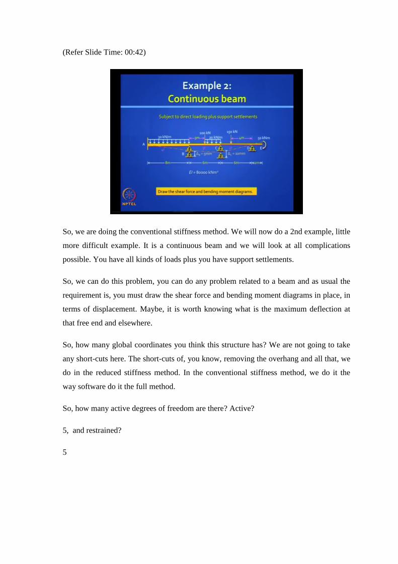
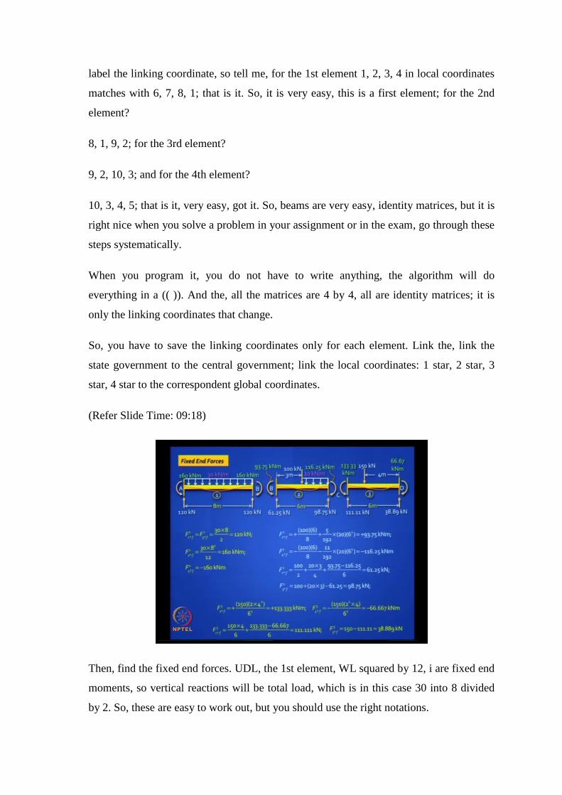
So, we are doing the conventional stiffness method. We will now do a 2nd example, little
more difficult example. It is a continuous beam and we will look at all complications
possible. You have all kinds of loads plus you have support settlements.
So, we can do this problem, you can do any problem related to a beam and as usual the
requirement is, you must draw the shear force and bending moment diagrams in place, in
terms of displacement. Maybe, it is worth knowing what is the maximum deflection at
that free end and elsewhere.
So, how many global coordinates you think this structure has? We are not going to take
any short-cuts here. The short-cuts of, you know, removing the overhang and all that, we
do in the reduced stiffness method. In the conventional stiffness method, we do it the
way software do it the full method.
So, how many active degrees of freedom are there? Active?
5, and restrained?
5

(Refer Slide Time: 02:01)
5, so if we look at the global coordinates, you have 5 active degrees of freedom: 4
rotational and 1 translational. The free end E can deflect as well as rotate and in the
numbering system, our preference will always be translation first and then rotation.
So, are you comfortable with this numbering: 1, 2, 3, 4, 5? These are all global
coordinates, which are active. We have also 5 restrained coordinates: 6, 7, 8, 9, 10; is
that ok? With that we have covered all the coordinates.
The size of our stiffness matrix will be 10 by 10. k AA will be 5 by 5 and that is the one
you need to invert. So, it is not a problem, that you can do manually, you will have to
resort to using some algorithm or using Matlab, but this just a demonstration of how
stiffness method can be used to solve any problem, any beam problem.
In terms of the coordinates, that we have selected, let us look at the load data. We have a
load vector, which is 5 by 1. Load vector is 5 by 1 because there are 5 active coordinates
and you will find that there is only 1 nodal load, namely , The moment at the free end E,
which is F5, which you will write as minus because anticlockwise is positive and the
moment applied is clockwise, so minus 50 kilo-Newton meter is the load. You also have
support settlements, so which coordinates are deflecting 8 and 9? So, D8 and D9 is
respectively 5 mm and 10 mm downward, which means a negative sign.

So, after you write down, you identify the coordinates, you should summarize the input
loading. There is some more loading on the structure, those are the distributed loads. The
distributed loads you have to find, convert into fixed end forces.
You have 3 beam elements and the local coordinates are shown here, actually you have 4
beam elements; 4 beam elements. The element 2 and element 3 are identical in terms of
span, but the difference is in terms of their flexural rigidity. So, if you see here, instead
of drawing 2 elements, I drew just 1 generic element and I said the span is 6 meters per
both, but for element 2 the EI value is 3EI and for element 3 the EI value is 2EI.
So, actually, you need to draw 4 elements, but we kind of saved spaced by doing this and
that overhang is also treated like any other element, that is, the 4th element and you have
4 degrees of freedom. Actually, you can draw just 1 element and the only thing, that
changes is the length and the EI, it is 1 2 3 4.
Now what do we do next? It is good to write down the solution procedure, so that you
have a road map.
(Refer Slide Time: 05:42)
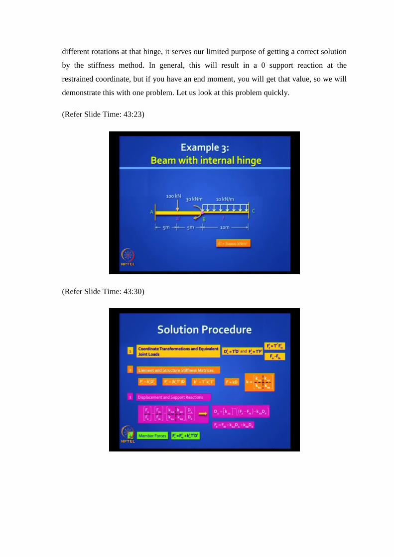
So, this is, you are familiar with this. First, you find out the transformation matrices, find
out the fixed end force vector, convert it into global coordinates. Find the net load vector.
The net load vector includes the nodal loads and the negative of the fixed end forces at
the active coordinates.

Then, you generate the element and structure stiffness matrices; we have done this many
times. Here, you will find the displacements and support reactions using the equilibrium
equations. Please note, here the displacement vector contains DR, which is not 0, not a
null vector because now you have support settlements.
So, you have to be careful to include that. Take the 1st equation, solve it, find the
unknown displacements, plug it into 2nd equation, find the support reactions and then
you can also use the unknown displacements to find the member forces.
Just want to remind you, that this last equation is familiar to us, what is it really? The
equation we have written in matrix form, it is nothing but the slope deflection equations.
Remember the good old MAB is equal to MFAB plus 4EI by L theta A plus 2EI by L
theta B minus 6EI by L into 5AB is actually nothing but F2 star. If you expand, this is
nothing but F2 star you got it.
Similarly, F4 star is the other slope deflection equation and F1 star and F3 star are what
you get, you can work out using equilibrium expressions for your shear forces at the 2
ends, is it clear? So, these are nothing but slope deflection equations.
(Refer Slide Time: 07:41)
Now, please write down the transformation matrices for the 4 elements. We have the
global coordinates, we have the local coordinates, it is easy because every transformation
matrix is an identity matrix. So, there is nothing much to write, only thing, you have to
label the linking coordinate, so tell me, for the 1st element 1, 2, 3, 4 in local coordinates
matches with 6, 7, 8, 1; that is it. So, it is very easy, this is a first element; for the 2nd
element?
8, 1, 9, 2; for the 3rd element?
9, 2, 10, 3; and for the 4th element?
10, 3, 4, 5; that is it, very easy, got it. So, beams are very easy, identity matrices, but it is
right nice when you solve a problem in your assignment or in the exam, go through these
steps systematically.
When you program it, you do not have to write anything, the algorithm will do
everything in a (( )). And the, all the matrices are 4 by 4, all are identity matrices; it is
only the linking coordinates that change.
So, you have to save the linking coordinates only for each element. Link the, link the
state government to the central government; link the local coordinates: 1 star, 2 star, 3
star, 4 star to the correspondent global coordinates.
(Refer Slide Time: 09:18)
Then, find the fixed end forces. UDL, the 1st element, WL squared by 12, i are fixed end
moments, so vertical reactions will be total load, which is in this case 30 into 8 divided
by 2. So, these are easy to work out, but you should use the right notations.
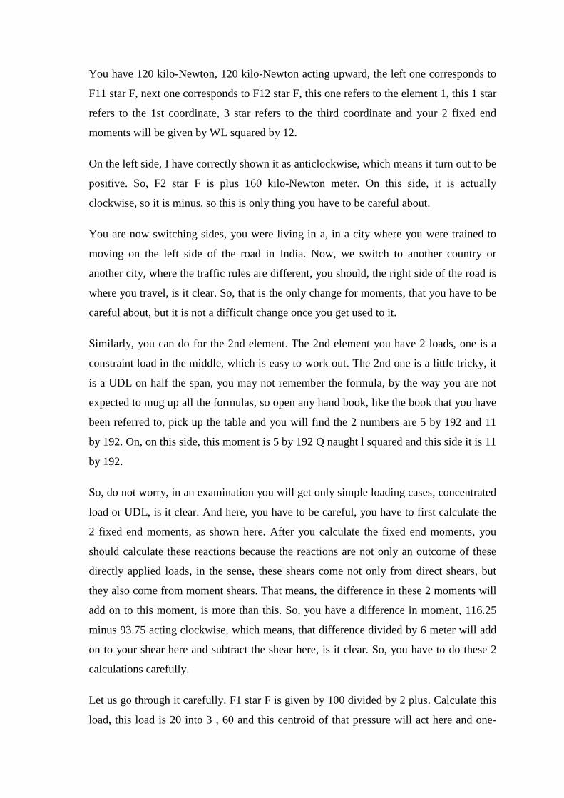
You have 120 kilo-Newton, 120 kilo-Newton acting upward, the left one corresponds to
F11 star F, next one corresponds to F12 star F, this one refers to the element 1, this 1 star
refers to the 1st coordinate, 3 star refers to the third coordinate and your 2 fixed end
moments will be given by WL squared by 12.
On the left side, I have correctly shown it as anticlockwise, which means it turn out to be
positive. So, F2 star F is plus 160 kilo-Newton meter. On this side, it is actually
clockwise, so it is minus, so this is only thing you have to be careful about.
You are now switching sides, you were living in a, in a city where you were trained to
moving on the left side of the road in India. Now, we switch to another country or
another city, where the traffic rules are different, you should, the right side of the road is
where you travel, is it clear. So, that is the only change for moments, that you have to be
careful about, but it is not a difficult change once you get used to it.
Similarly, you can do for the 2nd element. The 2nd element you have 2 loads, one is a
constraint load in the middle, which is easy to work out. The 2nd one is a little tricky, it
is a UDL on half the span, you may not remember the formula, by the way you are not
expected to mug up all the formulas, so open any hand book, like the book that you have
been referred to, pick up the table and you will find the 2 numbers are 5 by 192 and 11
by 192. On, on this side, this moment is 5 by 192 Q naught l squared and this side it is 11
by 192.
So, do not worry, in an examination you will get only simple loading cases, concentrated
load or UDL, is it clear. And here, you have to be careful, you have to first calculate the
2 fixed end moments, as shown here. After you calculate the fixed end moments, you
should calculate these reactions because the reactions are not only an outcome of these
directly applied loads, in the sense, these shears come not only from direct shears, but
they also come from moment shears. That means, the difference in these 2 moments will
add on to this moment, is more than this. So, you have a difference in moment, 116.25
minus 93.75 acting clockwise, which means, that difference divided by 6 meter will add
on to your shear here and subtract the shear here, is it clear. So, you have to do these 2
calculations carefully.
Let us go through it carefully. F1 star F is given by 100 divided by 2 plus. Calculate this
load, this load is 20 into 3 , 60 and this centroid of that pressure will act here and one-

fourth of it will come here, so 20 into 3 divide by 4 and, and the difference in the
moment divide by 6 will… Well, whichever way you want to write, it will actually be a
negative, the whole thing will be negative and you work this out.
To work out this load, you just add up all the loads and subtract this value 98.75. It is
worth doing a cross check because if you make an error here, even if your stiffness
matrices and transformation matrices are all perfect, your answers will be wrong, so be
careful in this step, especially when you have complicated loading, is it clear?
So, you got the 2nd one, the 3rd one. Similarly, you can work out, you have an eccentric
load, you know the formulas, is it clear. So, you should be able to generate the fixed end
forces for all the elements. The 4th element, if you remember, the overhang did not have
any intermediate load, it had only a nodal moment of 50 kilo-Newton meter. So, there is
no calculation to be done for the 4th one and you can put them all neatly in vector form.
(Refer Slide Time: 14:13)
In terms of element fixed end force vectors in the local axis system, F1 star f, F2 star f,
F3 star f, F4 star f, which in this case is a null vector. Please note, there are 4 items here,
4 components in these vectors, the 1st one is the force, the 3d one is the force, the 2nd
and the 4th ones are moments, so the unit should be correctly entered, is it clear. Had all
the units been the same, you could have put it outside, but since the units are different,
you have to put the units inside, clear.

What do we do next? You got these fixed end forces, you have got them in the local axis
system, so now you have to, you have to link it to the global axis system. How do you do
that?
Pre-multiply all these vectors with TI transpose. And TI is identity, TI transpose is also
identity, so you will get back these vectors. But along with them you get an additional
linking coordinate system, so that is what you get, just copy down those vectors and add
on those linking coordinates, which we discussed in the beginning. Is it clear, this step is
clear? Very easy to do.
What do you do next? What is our objective, or we are trying to find the solution to a
problem where we can deal with only joint loads. So, we have to convert these into, we
want to find the net load vector, which is, and also we want to find the, you know, the
fixed end forces, which accumulate at the restrained coordinates. So, what you need now
is the FA f and FR f at the structure level.
How do you do that? Well, you have already done the slotting here, the slotting is
already done, you have to accumulate everything, that comes in any slot and then
generate this fixed end force vector. Let us take a look, for example, at the first slot F1 f,
which belongs to the active coordinates, you pick up this value, then you pick up this
value that is all. So, you add up these 2, you will get this value.
Take the 2nd slot, the 2nd slot is this one, so you have to pick up this value and this
value, add it up algebraically, you will get this value and so on, and some of them will
remains with 0s. This is something that is accumulated in the active coordinate, so it will
operate as a load, but you must oppose it, you must put a negative sign. This is coming in
restrained coordinates, so just keep it there and add it to your reactions later, is it clear?

(Refer Slide Time: 17:20)
But you need, both of these, store it and now we are ready to generate the equivalent net
load vector F A minus F fA. If you remember, there is only 1 direct nodal load , minus
50 kilo-Newton meter acting at F 5. This is what you picked up from the previous
calculation; this is your net load vector.
If you want to draw it , it is worth drawing it, so you get a picture of what is going on,
this is what is happening. Now, how do you relate this to the original problem? What is
guaranteed if you really got the net load vector? Now, you have only F1, F2, F3, F4, F5,
you got, you converted all the loads to joint loads. What is the great advantage of this?
The great advantage is, you can now do a matrix solution to this problem.
But how do you know this is equivalent to the original problem? What is the
equivalence? The equivalence is, that if you analyze this and find the unknown
displacements: D1, D2, D3, D4, D5, they will be exactly equal to the D1, D2, D3, D4,
D5 you got in the original problem, with all those hang support settlements.
How so? Support settlements will bring in later, how so? Because we are doing super
position, we are taking a primary structure, putting the distributed loads and we are
adding this loading to that structure. So, in the primary structure, there are no
displacements. D1, D2, D3, D4, D5 are 0, so that is why this must be giving you the final
displacement. Is it clear? But you are right; we also have to add the indirect loads, which
we will in the formulation.

(Refer Slide Time: 19:06)
So, next step is to generate the stiffness matrices. We know this is standard matrix, we
discussed it yesterday. You can write it elegantly in this form because there are only 3
quantities: 12EI by L cubed, 6EI by L squared, 4EI by L and 2EI by L, the 4th one is c
divide by 2. So, if you write a small algorithm like this, especially if you are writing a
program, just ask it to generate this for all the 4 elements, so that is. For each element
spell out what is the length, what is the EI value, i value, what is and that is all you need,
then you get, you get the values of a b and c for all the 4 elements.
This is just an algorithmic way of generating the matrix; you can do it in your own way.
Is it clear? At the end of the day, you must get these 4 element stiffness matrices. Is it
clear?

(Refer Slide Time: 20:05)
These are properties of the structure; they do not depend on the loading, so you got k1
star, k 2 star, k 3 star, k 4 star. They are 4 by 4 matrices and you have to convert from the
element level to the global axis coordinates. So, you have to do TI transpose k star TI,
you will get back to k star, but you will get along with it the linking coordinate, so that is
what I have shown here.
Now, you are ready to assemble the structure stiffness matrices, how do you do that? The
slotting thing, we do not go back to those days, you have understood how to do that. You
have to program it and you will get it is a huge matrix, you will get, you get a 10 by 10
matrix, a very difficult to show the 10 by 10 in a small screen like this.
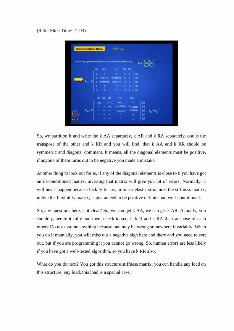
(Refer Slide Time: 21:03)
So, we partition it and write the k AA separately, k AR and k RA separately, one is the
transpose of the other and k RR and you will find, that k AA and k RR should be
symmetric and diagonal dominant. It means, all the diagonal elements must be positive,
if anyone of them turns out to be negative you made a mistake.
Another thing to look out for is, if any of the diagonal elements is close to 0 you have got
an ill-conditioned matrix, inverting that matrix will give you lot of errors. Normally, it
will never happen because luckily for us, in linear elastic structures the stiffness matrix,
unlike the flexibility matrix, is guaranteed to be positive definite and well-conditioned.
So, any questions here, is it clear? So, we can get k AA, we can get k AR. Actually, you
should generate it fully and then, check to see, is k R and k RA the transpose of each
other? Do not assume anything because one may be wrong somewhere invariably. When
you do it manually, you will miss out a negative sign here and there and you need to sort
out, but if you are programming it you cannot go wrong. So, human errors are less likely
if you have got a well-tested algorithm, so you have k RR also.
What do you do next? You got this structure stiffness matrix, you can handle any load on
this structure, any load, this load is a special case.

(Refer Slide Time: 22:58)
(Refer Slide Time: 23:33)
So, what should you do next? You should write down the equilibrium equations and pull
out the 1st equation. If you look at the first equation F A minus F fA is equal to k AA
into DA plus k AR into D R. It is convenient whenever you have D R to separate out k
AA separately. Plug in the values of F A minus F fA, which we have already completed
and D R, which we got at the input stage support settlements and then, solve for k AA D
A. After you get this, you pre-multiply this with k AA inverse and you got your
displacement.
You got your displacements, hopefully they are right, they are right if those numbers,
that you generated are right provided the calculations are right and please note, it is
important to write down the units.
If you remember the active degrees of freedom, all were rotations except one, the last
one, not the last one, 4th one, so that turns out to be 4.8 millimeters. You can actually
draw a sketch and check out, this is at the free end, it is 4.78 and next, you are ready to
because the rotations you cannot make out in a drawing, you know they just tell you
whether the rotation is clockwise or anticlockwise, those numbers do not have as much
meaning as deflections have, clear.
Now what is the next step? You have got the active displacement, next step, support
reactions. Take the 2nd equilibrium equation; this is where your fixed end force vector
comes in. Remember, F fR, which you calculated and stored and you have k RA D A and
you have k RR D R, multiply them out, you have these end moments. Yes, any doubt,
any doubt?
1st equation, you want me to go back?
Right
Do not get too mathematical, if you want you can write D A and put k A inverse there
and do it in 1 step. If I am doing it step-wise, this is convenient. You understand, I am
looking at that matrix, which I got, how do I get k, but you can do it in 1 step directly. As
long as you get the final answer, it makes sense.
Shall I proceed? You have got this what is and you, you got to see the reaction, so you
show the reactions, see whether it make sense. What is the next thing you should do
before you proceed? You should do a quick check because you might get funny results.
What is a check? Equilibrium, at least one equilibrium, so add up all the loads, see
whether they match. In this case I think the total downward load is 550 kilo-Newton, will
find, that the reaction also match.

(Refer Slide Time: 26:10)
(Refer Slide Time: 26:25)

(Refer Slide Time: 26:32)
Now, you can find, these are the slope deflection equations that I talked about, invoke
those equations, you will get the element end force vectors. So, we have to do this for
each of these elements and find, you get the answers for 1st element, 2nd element, 3rd
element, 4th element. Interpret the results, draw your shear force diagram, draw your
bending moment diagram, you got everything, is it clear. Just a demonstration of a
slightly difficult problem with 5 active degrees of freedom.
Now, let us, so we have almost covered everything, but some few more tricky issues to
cover, I want to deal with a problem normally we avoid in structural analysis.

(Refer Slide Time: 27:07)
How do you handle internal hinges? Remember, we did this problem yesterday, now I
have inserted an internal hinge at B. Slope deflection equation, you will find it different;
moment distribution, find it difficult; matrix method, let us see how to handle it, any
suggestions?
First question, do you understand what happened if you apply a concentrated moment at
B of 30 kilo-Newton meter. If there was no hinge, you could apply, that 30 kilo-Newton
meter exactly at B. If there is a hinge, you cannot do it because the hinge does not allow
any moment transfer. So, it has to be applied either to the left of B, infinitesimally to the
left or to the right of the B. And you have to ask the site engineer or the examiner, please
state your problem more correctly, where is this 30 kilo-Newton meter being applied, is
it to the left or right, then only I can give you a solution. That is the right question to ask,
you cannot exactly apply it at B because of that hinge.
So, here if you notice, I put it slightly to the left, so that 30 kilo-Newton meter is not a
nodal moment, it is now a member end moment applied at AB, that is the first thing to
note. But how the hell do we handle that internal hinge, any suggestions.
There are problems, what are the problems, at least tell me the difficulties you visualize
with the internal hinge.
There is movement along vertical direction
How many active degrees or freedom did you have without that hinges?
Without the hinge?
We did this problem yesterday.
We had 2 at B where a translation and a rotation. Now, what is the difficulty you
encounter?
What is the difficulty you encounter with those 2?
Theta is not, theta is not continuous
When we had 1 and 2, D1 was the vertical deflection at B, D2 was the anticlockwise
rotation at B. Now, D2 is a problem, why? Because D2 to the left of B and D2 to the
right of B are different and we are really not interested in those displacements, are we?
We just wanted the bending moment and shear force diagram.
So, there are people have broken their heads on how to crack this problem, I will give
you one elegant solution unless you have something to contribute. 4 degree, I want to
minimize my work, yeah, you can do all that, but it is not going to be easy, you try it, we
do not have much time to discuss all that. We want to minimize our work; we do not
want to do more work than what we did without the hinge. We want to do less work
actually, preferably. But you can do less work because if you notice the moment M BA
is known, it is 30 kilo-Newton meter; the moment M BC is known, it is 0 kilo-Newton
meter, so at least you know, that much you know what is going on inside that beam at B.
So, if you notice, there are 2 characteristics about an internal hinge, first is no transfer of
bending moment is allowed across the hinge, any internal hinge. The second is, you have
this problem of rotational compatibility, which we just discussed. The 2 rotations on
either side of that hinge will not be equal to each other, agree.
It will help if you pay attention to what we are discussing and do the assignment later,
thank you. How do we model the internal hinge?
Well, since it took some, some significant research to get the solution, you cannot just
give it in a jiffy. Let me tell you one way of handling it, you can, you can, that is, what
element?

Which can deform in this direction.. which can allow..
Try this; it is not the time to think aloud because it takes lot of effort to get a right
solution so here is this.
Introduce a moment release at beam, at the beam end and modify your element stiffness
and fixed end forces, which is what we did in the reduced element stiffness method.
Remember, whenever there was hinge we took advantage of it, but we never took
advantage of an internal hinge, we will do it there also. So, first modify your stiffnesses
to account for the known fact, that you got a moment release at the hinge, you have a
moment release, the moment cannot get transferred beyond the end point.
The 2nd thing you need to do is to introduce a clamp at the hinge, whereby you convert
D2 from an active degree of freedom to a restrained degree of freedom, you clamp it,
otherwise you will get into difficulty. We will explain this one by one.
(Refer Slide Time: 33:05)
So, let us take the first one. You have got a beam, the hinge can be at one end, left end,
right end or both ends, you can have 2 hinges inside a structure, so let us handle all
possible. For example, the balance cantilever bridge has 2 hinges, internal hinges in the
suspended span region.
So, let us take the first one where you have 1 hinge at the start node, which is at the left
end. We are not reducing the number of degrees of freedom in that element level, you

have 1 star, 2 star, 3 star, 4 star, as we had earlier. If you were to allow a moment release
at 2 star, that means, F2 star is permanently 0. How would you write the stiffness matrix,
can you tell me?
You know, a conventional stiffness matrix. 12EI by L cube was the first term that will
now change to what?
It is like you have got a hinge support at 2 star, you have got a hinge support, permanent
hinge support, yes, 3EI, very good, so I will show you this and then, we will discuss this.
First thing to notice in that matrix, the 2nd row and 2nd column will be 0 just like,
remember when we did for the truss element, we said, the shear force is always 0, so the
2nd and 4th row were 0s. So, first thing you do is, no matter what happens, F2 star will
be always 0; is it clear.
So, these 2, 2nd row and 2nd column will be 0, then you have to fill in this, so how do
you fill in this?
So, let us take a look at that.
(Refer Slide Time: 35:18)
This is a hinge, this is fixed and we want to apply D i 1 star equal to 1. So, what would
be the deflected shape? If I let this go up by 1, this must come back here, what will be
the deflected shape? It will be like this, like a cantilever and the force I need to apply

here to lift it up will be, how much this is? What I call k the ith element 1 star 1 star,
what I get here is always permanently, this is k i 2 star 1 star this will always be 0
because of that hinge.
And the reaction, that I get here is k i 3 star 1 star and the moment, that I get here, k i 4
star 1 star. By now, I hope you know the physical meanings of this. Now, if I, this is like
a cantilever whose length is L I, flexural rigidity is EI, so if this deflection is unity, what
do you think this force is?
No doubts about that, 3EI by L i cubed.
If this is so, then this must be minus EI for equilibrium, minus 3EI and what will this be,
is a cantilever. Now, what is a moment you get? Is it plus or minus?
Plus, plus
It will be plus…
EI by L square
So, little thinking and you can generate, clear. Does not match with what we have got in
on the screen, so likewise can you generate all the others? It is not difficult, so this is
easy to do once you understood it. We will be doing this in the reduced element stiffness
method anyway, so it is, we are borrowing an idea from there.
(Refer Slide Time: 38:07)

What happens if you have the hinge at the end node like that? Now, which row and
which column will turn out to be 0? The 4th row and 4th column will be 0 and you are
basically playing around with these numbers, you, we will get something like that.
What happens if both ends are hinged, have internal hinges, so you will get something
like that. Have you understood? Better get this clear, the stiffness matrices you must be
thorough about in generating using a physical approach. This was the physical approach,
now we have no difficulties in generating.
We are ready, we modified the stiffnesses to handle moment release and we know, which
to use, where, left end you know, which one to use, right end, both ends, we can handle,
but this alone is not enough, you will also have to modify the fixed end force vectors and
that is interesting. Usually you do not have concentrated moment acting, but if by chance
you have one, you should be able to handle that also.
(Refer Slide Time: 39:24)
So, I am giving you the case where you have a concentrated moment acting at that
release location , M naught. The question is, how to find out these remaining fixed end
forces?
One of them, you know, it is either 0 or a given moment, which is applied externally.
How to generate expression for the other 3? So, you remember, we have discussed this

earlier. If you know what is happening in a fixed, fixed beam, you know what to do for a
propped cantilever; you have to do just that.
So, it is not really difficult, so the answer is, find out what is happening for a fixed beam.
You have tables, which will give you the fixed end forces in a prismatic fixed beam
subject to any arbitrary loading. Then, to this you have to add, you have to do something,
so that the moment at B is not 0, is M naught, then only you get back the original picture,
so you will get something like that.
So, you allow to rotate and then, you will get some reaction at the other end, what will
be, what will be those reactions? They will be carry over moment, remember we have
done this before.
Let me explain once more. Here, you have to reverse this moment, then only you will get
0 from the loading, but if you, in case you have a concentrated moment here, you better
apply that as well.
If you apply this here, half of it will get transferred here, so half of it will get transferred
here and the shears can be easily calculated by the, sum of those 2 moments divide by
the span. So, that is all you have to do and when you add up these 2 quantities, you will
get those expressions.
And I am suggesting, do not do any such formulas, just look at the beam and figure out
what those modified fixed end forces are. We will demonstrate it with an example. But
have you got the hang of it? That is all; if you do these 2 tricks, you can handle the
moment release, but now we need to worry about why do we need that imaginary clamp?

(Refer Slide Time: 41:24)
By reducing the rotational stiffness components in the 2 beam elements adjoining the
internal hinge location, to the left and to the right, the resultant rotational stiffness of the
structure, corresponding to this rotational degree of freedom, let us say some global
coordinate q, in this example it is coordinate number 2, is reduced to 0, agreed.
Because you have 0 rows and 0 columns there, when you do the slotting and you make
the structure stiffness matrix k 22, the diagonal element will have a value equal to 0; that
is not good. Why is it not good? It belongs to k AA, k AA becomes singular, you cannot
invert it; you cannot find a solution.
So, what do you do? So, that is a problem. You have a diagonal element in your structure
stiffness matrix because of moment release, which has 0, so what do you do? This is
where someone got this brilliant idea, you shift it away from the active degrees of
freedom, put it in the reactive coordinates; put it in the reactive coordinates, you just shift
it, so that you do not have to invert it, does not come in the matrix component, that you
need to invert. So, that is a trick you do.
And that is called an imaginary clamp. Imagine, there, there is a support, not only you
get an internal hinge, you get a clamp along with it, so that it is a restrained coordinate.
So, we can get around this difficulty by visualizing an imaginary clamp at the internal
hinge location, arresting the rotation that is, setting D q equal to 0. Although this is not
physically a correct representation because rotations are possible and you have 2
different rotations at that hinge, it serves our limited purpose of getting a correct solution
by the stiffness method. In general, this will result in a 0 support reaction at the
restrained coordinate, but if you have an end moment, you will get that value, so we will
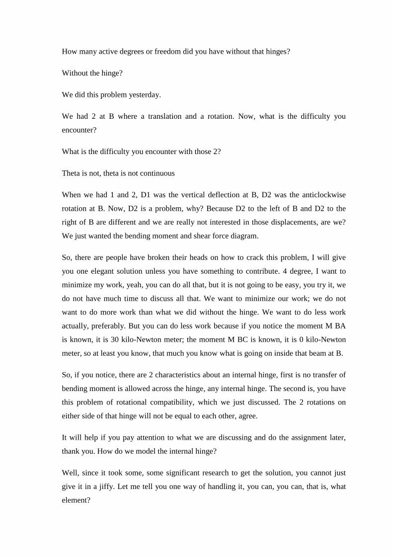
demonstrate this with one problem. Let us look at this problem quickly.
(Refer Slide Time: 43:23)
(Refer Slide Time: 43:30)

(Refer Slide Time: 43:32)
We have done this problem earlier. Now, we just have an internal hinge there, the
procedure is similar, so remember we did this earlier, I have just reproduced what we did
earlier. Only change we now need to make is the coordinate 2 has to be restrained, so put
a slash on that, so here only 1 active degree of freedom. And the input data is, you have
only, you do not have any direct loads because that 30 kilo-Newton meter is not going to
the global coordinate, is going to the member end and there are no support settlements. Is
it clear? So, input data is this; so far it is clear.
(Refer Slide Time: 44:11)

Next, find the fixed end forces, but now you give the release. We did the same problem,
but at B we fixed it. Can you find fixed end forces for this? Yeah, that is easy to do; we
have done this before, propped cantilever.
What about the 2nd element? By the way, your 30 kilo-Newton meter is now coming
here as, as local load in this moment, so we shifted it from a nodal load to an
intermediate load, that is the change with it. Earlier, it was going to the structure, going
to 2 elements simultaneously, now it is gone to 1 element as an intermediate load, which
will generate a fixed end moment. Is it clear, makes good sense.
Similarly, you do for the 2nd element, take advantage of that hinge, tell me what is the
formula for that fixed end moment? WL square by 12 is the standard formula.
3 by 2W L
One and half times, it works out to WL square by 8, you know how to do all those
calculations and the moment at B is 0.
(Refer Slide Time: 45:16)
You got the fixed end forces, what do you do next? Write them down in vector form,
then, yeah, you do the transformation, put the linking coordinates, assemble them
together. Now, you have only 1 active degree of freedom, so F1 f and then find the
resultant force vector and this is what you have done. Really, that resultant force is force
acting at that location. Is it clear, with an imaginary clamp?

(Refer Slide Time: 45:44)
This part you can generate. Remember those formulas, which we generated for the 2
elements, can you generate the elements stiffness matrices? Then can you multiply them
with the identity matrices and put the linking coordinates and you assemble these
structure stiffness matrices, you will get lots of 0s.
(Refer Slide Time: 46:20)
The 2nd row and 2nd column are dangerously 0, but do not worry, they do not belong to
the active degree of freedom, so let them hang around there, find k AA is now 1 by 1,

earlier it was 2 by 2, invert k AA. Solve the 1st equation, your unknown displacement
comes a huge displacement, because of that internal hinge you have 102 mm.
(Refer Slide Time: 46:33)
(Refer Slide Time: 46:47)

(Refer Slide Time: 46:53)
And find the fixed end forces, you will correctly get the answers and write down your, I
mean, these are your support reactions, see if they satisfy equilibrium, find out your
member forces at element end, same formula, everything follows nicely and draw your
diagrams.
So, powerful method of handling internal hinges normally not taught, not commonly
encountered, but in case you have them, you know how to deal. Is it clear?
We will stop. Thank you.

KEYWORDS
Matrix Analysis
Stiffness matrix
Support settlement
Internal hinge