Äktapilot™ - arcscientific.com · important user information this document is a handbook with...
TRANSCRIPT

Instrument Handbook
ÄKTApilot™


Important user information
This document is a handbook with complementing information to the Operating Instructions. All users must read the safety instructions in the ÄKTApilot Operating Instructions to fully understand the safe use of the ÄKTApilot system, before installing, using, or maintaining the system.
Do not operate the ÄKTApilot system in any other way than described in the user documentation, or you may be exposed to hazards that can lead to personal injury, and damage the equipment.
WARNING!
The WARNING! sign highlights instructions that must be followed to avoid personal injury. Do not proceed until all stated conditions are clearly understood and met.
Caution!
The Caution! sign highlights instructions that must be followed to avoid damage to the product or other equipment. Do not proceed until all stated conditions are met and clearly understood.
Note
The Note sign is used to indicate information important for trouble-free and optimal use of the product.
CE Conformity
This product complies with the European directives listed in the table, by fulfilling the corresponding harmonized standards.
2006/42/EC Machinery Directive (MD)
2006/95/EC Low Voltage Directive (LVD)
2004/108/EC Electromagnetic Compatibility (EMC) Directive
A copy of the corresponding Declaration of Conformity is available on request.
The CE symbol and corresponding declaration of conformity, is valid for the instrument when it is:
– used as a stand-alone unit, or
– connected to other products recommended or described in this manual, and
– used in the same state as it was delivered from GE Healthcare except for alterations described in this manual.
Recycling
This symbol indicates that the waste of electrical and electronic equipment must not be disposed as unsorted municipal waste and must be collected separately. Please contact an authorized representative of the manufacturer for information concerning the decommissioning of equipment.
WARNING!
This is a Class A product. In a domestic environment, it might cause radio interference, in which case the user might be required to take appropriate measures.
ÄKTApilot Instrument Handbook 18-1162-95 Edition AH


Contents
Contents
1 Introduction1.1 The Instrument Handbook ............................................................................................................................71.2 ÄKTApilot system ...............................................................................................................................................81.2.1 System control ...............................................................................................................................................81.2.2 Separation unit components ..................................................................................................................91.2.3 Installation and localization of system...............................................................................................91.2.4 Identification and rating labels ...........................................................................................................101.2.5 Recycling and disposal ...........................................................................................................................111.3 Operating principles ......................................................................................................................................121.3.1 Liquid flow path .........................................................................................................................................121.3.2 Liquid delivery .............................................................................................................................................131.3.3 Mixing..............................................................................................................................................................141.3.4 Sample application ...................................................................................................................................141.3.5 Columns .........................................................................................................................................................151.3.6 Detectors and monitors..........................................................................................................................151.3.7 Air trap and air sensors...........................................................................................................................161.3.8 Tubing and connectors...........................................................................................................................161.3.9 Fraction collection.....................................................................................................................................161.4 Sanitization of the flow path .....................................................................................................................171.5 Associated documentation ........................................................................................................................17
2 Basic operation2.1 Starting the system ........................................................................................................................................192.2 Performing a run .............................................................................................................................................202.2.1 Creating a method....................................................................................................................................202.2.2 Preparing the system...............................................................................................................................202.2.3 Running a method.....................................................................................................................................202.3 After the run ......................................................................................................................................................212.4 Calibration ..........................................................................................................................................................212.4.1 Calibrating the pressure sensors .......................................................................................................222.4.2 Calibrating the pH electrode ................................................................................................................252.4.3 Calibrating the conductivity cell .........................................................................................................272.4.4 Measuring the real UV cell length......................................................................................................30
3 Maintenance3.1 User maintenance schedule .....................................................................................................................363.2 User maintenance instructions ................................................................................................................393.2.1 Cleaning the system.................................................................................................................................393.2.2 System pump and sample pump.......................................................................................................403.2.3 Membrane valves ......................................................................................................................................423.2.4 UV cell .............................................................................................................................................................433.2.5 pH electrode.................................................................................................................................................443.2.6 Conductivity cell .........................................................................................................................................453.2.7 Pressure sensors........................................................................................................................................453.2.8 Air sensors.....................................................................................................................................................463.2.9 Air trap ............................................................................................................................................................463.3 Replacing spare parts ...................................................................................................................................473.3.1 General instructions .................................................................................................................................473.3.2 System pump P-907 and sample pump P-908 ...........................................................................473.3.3 Mixer ................................................................................................................................................................533.3.4 Valve block....................................................................................................................................................543.3.5 Pressure sensor (2-port or 3-port union) ........................................................................................563.3.6 Pressure sensor (pump outlet manifold).........................................................................................57
ÄKTA pilot Instrument Handbook 18-1162-95 Edition AH
3.3.7 Air sensors.....................................................................................................................................................583.3.8 UV cell .............................................................................................................................................................593.3.9 pH electrode.................................................................................................................................................613.3.10 Conductivity cell .........................................................................................................................................623.3.11 Air trap ............................................................................................................................................................633.4 Priming the system ........................................................................................................................................643.4.1 Automated priming...................................................................................................................................643.4.2 Manual priming ..........................................................................................................................................64

Contents
4 Troubleshooting4.1 UV curve ............................................................................................................................................................. 654.2 Conductivity curve ......................................................................................................................................... 664.3 Pressure curve ................................................................................................................................................. 684.4 System pump and sample pump ........................................................................................................... 694.5 Mixer ..................................................................................................................................................................... 704.6 Membrane valves ........................................................................................................................................... 704.7 Pressure sensors ............................................................................................................................................ 714.8 Air sensors ......................................................................................................................................................... 714.9 Checking the pump pressure ................................................................................................................... 714.10 Running the installation test ..................................................................................................................... 734.10.1 Testing pressure stability....................................................................................................................... 734.10.2 Preparing the installation test............................................................................................................. 744.10.3 Running the installation test ................................................................................................................ 744.10.4 Evaluating the installation test results ............................................................................................ 764.10.5 Correcting faulty evaluation results ................................................................................................. 784.10.6 Test protocol................................................................................................................................................ 79
5 Reference information5.1 System description ........................................................................................................................................ 815.1.1 ÄKTApilot system....................................................................................................................................... 815.1.2 Indicators and controls on the separation unit .......................................................................... 825.1.3 Component location ................................................................................................................................ 835.1.4 Electrical connections ............................................................................................................................. 845.1.5 System flow path....................................................................................................................................... 885.1.6 Piston rinsing system............................................................................................................................... 915.1.7 Column tubing, inlet tubing, and outlet tubing ........................................................................... 925.2 Component description ............................................................................................................................... 955.2.1 Pump P-907 and P-908 .......................................................................................................................... 955.2.2 Membrane valve........................................................................................................................................ 995.2.3 Mixer M-905...............................................................................................................................................1015.2.4 pH electrode and cell holder..............................................................................................................1015.2.5 Monitor UV-901 and UV cell ...............................................................................................................1025.2.6 Conductivity cell.......................................................................................................................................1035.2.7 Pressure sensor........................................................................................................................................1045.2.8 Air trap..........................................................................................................................................................1055.2.9 Air sensor 925 and 940.........................................................................................................................1055.2.10 Online Filter (optional)............................................................................................................................1065.2.11 Frac 950 (optional) ..................................................................................................................................1065.3 Specifications .................................................................................................................................................1075.3.1 Technical specifications.......................................................................................................................1075.3.2 System performance specifications ..............................................................................................1145.3.3 ÄKTApilot component materials ......................................................................................................1155.4 Chemical resistance guide and chemical compatibility ............................................................1165.5 Ordering information ..................................................................................................................................118
Index................................................................................................. 123
6 ÄKTA pilot Instrument Handbook 18-1162-95 Edition AH

Introduction 1
1 Introduction
ÄKTApilot™ is a high performance, automated liquid chromatography system. The system is designed for process development, process scale-up and scale-down, and small scale production.
In process development, ÄKTApilot simplifies the transition from laboratory purification to full scale production. Scale-up to production is predictable and trouble-free. It can also be used in scale-down studies in process robustness, cleaning and virus validation, media selection, media lifetime studies, and method scouting.
In small-scale production, the system can be used to produce purified material for clinical testing programs, or for small-scale production of diagnostic or therapeutic products.
ÄKTApilot system is based on proven liquid chromatography techniques, such as ion exchange, gel filtration, affinity chromatography, and hydrophobic interaction. The system can be used with pre-packed columns as well as with standard laboratory and pilot-scale columns packed with media. ÄKTApilot can also be used for packing columns.
ÄKTApilot system is biocompatible, hygienic and sanitizable. It meets all GLP and cGMP demands for Phase I–III in drug development and final-scale production.
ÄKTApilot features:
• Liquid flow rates from 4 to 800 ml/min. (The gradient performance is limited from 400 to 800 ml/min. See also ÄKTApilot Operating instructions.)
• Operating pressure up to 20 bar.
1.1 The Instrument HandbookThis handbook provides safety instructions, technical information and basic operating instructions for ÄKTApilot system. In addition, maintenance schedules and instructions for troubleshooting and user maintenance are included.
ÄKTApilot Instrument Handbook 18-1162-95 Edition AH 7

1 Introduction1.2 ÄKTApilot system
1.2 ÄKTApilot systemÄKTApilot system comprises ÄKTApilot separation unit and a PC. A flat-screen monitor is included in the system.
Fig 1-1. The ÄKTApilot system
1.2.1 System controlUNICORN™ control system controls and supervises the ÄKTApilot chromatography system. It runs on the PC under Windows® XP operating system, and includes hardware for interfacing the controlling PC to the chromatography liquid handling parts of ÄKTApilot.
UNICORN controls the run data acquisition from sensors and monitors. UNICORN also evaluates results and generates reports.
8 ÄKTApilot Instrument Handbook 18-1162-95 Edition AH

Introduction 1
1.2.2 Separation unit componentsThe location of the components in the separation unit is shown in the following figure.
Fig 1-2. Location of components
1.2.3 Installation and localization of system
ÄKTApilot is designed for indoor use only. It requires a working area of about 200 × 80 cm (width × depth) and should be placed on a stable laboratory bench that can withstand a minimum weight of 200 kg.
Mixer
Air sensor 2(on left-hand
panel)
Sample pump
System pump,module A and B
Outlet valve V8
UV cell
Conductivity cell
pH electrode
Column valve V7
Pressure sensor 3
Pressure sensor 1
Flow direction valve V5
Air trap valve V4
Column valve V6
3-port union with pressure sensor 4
2-port union with
Air sensor 1
Air trap
Sample valve V3 Inlet valve V1 Inlet valve V2
Outlet valve V9
WARNING! Installation, moving and service of ÄKTApilot must only be performed by authorized GE service personnel.
CAUTION! To maintain correct ventilation, the system requires a minimum clearance of at least 0.3 m on all sides. Do not block the ventilation inlets (underneath the system and next to the front panel) or outlets on the system.
ÄKTApilot Instrument Handbook 18-1162-95 Edition AH 9
1 Introduction1.2 ÄKTApilot system
See section 5.3.1 for detailed technical specifications.
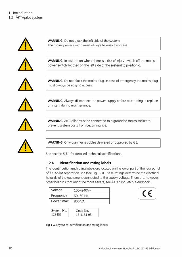
1.2.4 Identification and rating labelsThe identification and rating labels are located on the lower part of the rear panel of ÄKTApilot separation unit (see Fig. 1-3). These ratings determine the electrical hazards of the equipment connected to the supply voltage. There are, however, other hazards that might be more severe, see ÄKTApilot Safety Handbook.
WARNING! Do not block the left side of the system. The mains power switch must always be easy to access.
WARNING! In a situation where there is a risk of injury, switch off the mains power switch (located on the left side of the system) to position o.
WARNING! Do not block the mains plug. In case of emergency the mains plug must always be easy to access.
WARNING! Always disconnect the power supply before attempting to replace any item during maintenance.
WARNING! ÄKTApilot must be connected to a grounded mains socket to prevent system parts from becoming live.
WARNING! Only use mains cables delivered or approved by GE.
Voltage
Frequency
Power, max
100–240V~
50–60 Hz
800 VA
10 ÄKTApilot Instrument Handbook 18-1162-95 Edition AH
Fig 1-3. Layout of identification and rating labels
System No. Code No.123456 18-1164-95

Introduction 1
1.2.5 Recycling and disposalThis symbol indicates that the waste of electrical and electronic equipment must not be disposed as unsorted municipal waste and must be collected separately. Please contact an authorized representative of the manufacturer for information concerning the decommissioning of your equipment.
ÄKTApilot Instrument Handbook 18-1162-95 Edition AH 11

1 Introduction1.3 Operating principles
1.3 Operating principlesThis section gives an introduction to the function of ÄKTApilot separation unit.
ÄKTApilot contains all the fluid handling components required to perform buffer delivery and mixing, sample application, and in-line monitoring. The individual control units for the fluid handling components are located inside ÄKTApilot separation unit.
1.3.1 Liquid flow path
Fig 1-4. The liquid flow path of ÄKTApilot
1 The sample valve selects an appropriate sample inlet. The sample pump then delivers the sample solution to the column via a pressure sensor, the flow direction valve and the selected column valve. An air sensor can be used on the inlet tubing to detect when the sample container is empty.
2 The inlet valves select buffer. The system pump then delivers the buffer through a pressure sensor and a mixer to the air trap valve. The flow can also be directed through an air trap (used for column protection).
Waste2
System pump P-907A B
Mixer
Inletvalve (V1)
Columnvalve(V7)
Samplevalve (V3)
WasteF1
On-line filter(optional)
UV
CONDSample pumpP-908
Air trap
Air trapvalve(V4)
Inletvalve (V2)
Flowdirectionvalve (V5)
Columnvalve(V6)
Air sensor (1)
Air sensor (2)
Outletvalve(V8)
Outletvalve(V9)
Pressuresensor (2)
Pressuresensor (1)Pressure
sensor (3)
Pressuresensor (4)
pH
Fractioncollection
Buffer containersSample containers
1 2 3 4 1 2 3 4
1 3 4
1
4
1
2
3
4
1 3 4
8 7 6 5
1 2 3 4
4 3 2 1
12 ÄKTApilot Instrument Handbook 18-1162-95 Edition AH

Introduction 1
3 After the air trap valve, the buffer flow is directed through an air sensor and a pressure sensor to the flow direction valve. The air sensor is used to prevent air from entering the column.
4 The flow path continues through one of the column valves to the column. The flow passes through the packed column where the separation takes place.
5 The flow then passes a pressure sensor, the pH cell holder, the conductivity cell, and the UV cell.
6 The flow path continues to the outlet valves, which are used to divert the flow to waste or fraction collection.
Pressure sensors continuously monitor the pressure in the flow path.
1.3.2 Liquid delivery
System pumpThe system pump, P-907, is a high-performance laboratory pump producing an accurately controlled liquid flow. It is a low pulsation pump equipped with two pump modules; A and B. This allows for binary gradients with efficient mixing.
A pressure sensor (Press1) is connected to pump module A (the left-hand pump heads). The pressure sensor can be used in combination with an over-pressure alarm function, which is controlled from UNICORN.
The pump heads are equipped with check valves at the system flow inlet and outlet, and at the rinsing flow outlet.
The system pump has an operating flow rate range up to 800 ml/min in isocratic mode (400 ml/min in gradient mode) and a maximum allowed pressure of 20 bar.
Sample pumpThe sample pump, P-908, is identical with the system pump but has only one pump module. P-908 is also equipped with a pressure sensor (Press2).
ÄKTApilot Instrument Handbook 18-1162-95 Edition AH 13

1 Introduction1.3 Operating principles
Membrane valvesStepper motor-actuated membrane valves control the liquid flow in the separation unit. The valves are located in nine valve blocks.
A valve block consists of a connection block containing the ports and the membranes, and a mechanical housing containing the stepper motors, cams and actuating pistons.
The valve blocks have different numbers of inlet and outlet ports depending on their position in the flow path.
There are six main types of valve block:
• Inlet valve V1 and V2 and sample valve V3
• Air trap valve V4
• Flow direction valve V5
• Column valve V6 and V7
• Outlet valve V8
• Outlet valve V9
The valve seats in the valves have two different sizes in order to withstand the operating pressure in the flow path where the valve is located.
1.3.3 MixingBuffers delivered by the system pump are dynamically mixed by an electrically operated mixer. The volume of the mixer chamber included in the system is 5 ml.
1.3.4 Sample applicationThe sample solution is applied directly onto the column by the sample pump or the system pump.
14 ÄKTApilot Instrument Handbook 18-1162-95 Edition AH

Introduction 1
1.3.5 ColumnsA wide range of columns for ion exchange, gel filtration, hydrophobic interaction and affinity chromatography is suitable for use with ÄKTApilot. It includes some pre-packed columns as well as standard laboratory and pilot-scale columns that can be packed with media using ÄKTApilot.
Contact your local GE representative for recommended columns.
1.3.6 Detectors and monitorsÄKTApilot is equipped with detectors for continuous in-line measurement of pH, conductivity and UV absorbance. The detectors provide accurate and reliable monitoring.
The flow cells are connected close together, which minimizes band broadening and time delay between the detectors. The flow cells are easily accessible from the front panel to facilitate maintenance.
pH measurementThe pH electrode is mounted in the pH cell holder after pressure sensor 4 in the flow path. The electrode is in continuous contact with the liquid. The pH monitor provides pH measurement in the range 1–14 (2-12 within specifications).
Conductivity measurementThe conductivity cell is placed after the pH electrode in the flow path. It is used to verify gradients, follow peak positions relative to ionic strength, and for temperature measurement using a built-in sensor. The measurement range is 1 µS/cm to 999.9 mS/cm.
UV absorbance measurementThe UV cell is placed after the conductivity cell in the flow path. It is used for measuring the UV absorbance of the liquid. The location of the UV cell near the outlet minimizes the delay volume during fractionation. Up to three wavelengths can be measured simultaneously in the range 190–700 nm.
WARNING! OVER-PRESSURE. Use columns that withstand expected pressures. If not, the columns might rupture, resulting in injury.
WARNING! OVER-PRESSURE. The flow rate may under no circumstances exceed the specified column maximum flow rate. The flow might affect the packed column, causing the pressure to exceed the specified column maximum pressure.
ÄKTApilot Instrument Handbook 18-1162-95 Edition AH 15

1 Introduction1.3 Operating principles
1.3.7 Air trap and air sensorsThe buffer flow can be directed through an air trap by the air trap valve V4. The air trap is used for removing air from the buffer in order to enhance system performance and to prevent air from damaging the column performance.
There are also two air sensors in the system for preventing air from entering and damaging the packed column. The air sensor at the sample inlet detects air in the sample inlet tubing, for example, when the sample container is empty. The other air sensor is located between the air trap valve V4 and the flow direction valve V5.
Note: Make sure that the air sensors are filled with liquid before enabling. If not, an alarm will be raised immediately and the system set to Pause.
1.3.8 Tubing and connectorsAt delivery of ÄKTApilot system, all internal tubing is connected. The tubing has an inner diameter (i.d.) of 2.9 mm and an outer diameter (o.d.) of 3/16", and is made of ETFE. The connectors have rubber O-rings for proper sealing and sanitizability.
The system inlet and outlet tubing is packed separately at delivery. The inlet tubing has i.d. 6 mm and o.d. 13 mm and is equipped with TC connectors at both ends. The outlet tubing has i.d. 2.9 mm and o.d. 3/16" and the same type of connector as the internal tubing at one end.
Small-bore tubingTubing with i.d. 1.6 mm is available to enhance system performance at low flow rates. The tubing replaces the original tubing i.d. 2.9 mm tubing from the sample valve and the inlet valves to the outlet valves. Observe that when using this tubing, the system flow path might not be sanitizable.
1.3.9 Fraction collectionWhen the purified material has passed the monitor flow cells, it can be collected in fractions using the outlet valves. The outlet valves have 8 outlets in total. The minimum volume for a fraction is 40ml.
A separate fraction collector, e.g. Fraction Collector Frac-950, can be connected to the outlet valves for collecting multiple fractions. Observe that when using Frac-950, the maximum allowed flow rate during fractionation is 100 ml/min.
16 ÄKTApilot Instrument Handbook 18-1162-95 Edition AH

Introduction 1
1.4 Sanitization of the flow pathThe fluid handling components in ÄKTApilot have been designed to be compatible with recommended sanitization procedures. The Method Wizard includes a ready-made method for sanitizing the system. To facilitate compliance with GLP and cGMP requirements, all wetted parts in the flow path are replaceable.
Note: The circlips are not resistant to alkali and acids.
More information about sanitizing the system is found in the ÄKTApilot Operating instructions.
1.5 Associated documentationThe documentation listed below is also included with ÄKTApilot system.
The ÄKTApilot Operating Instructions contains operating instructions.
The ÄKTApilot User Manual contains operating instructions.
The ÄKTApilot Safety Handbook contains safety information.
UNICORN control system package includes three manuals:
• Getting Started
• User Reference Manuals (2 pcs.)
• Administration and Technical Manual
ÄKTApilot Instrument Handbook 18-1162-95 Edition AH 17

1 Introduction1.5 Associated documentation
18 ÄKTApilot Instrument Handbook 18-1162-95 Edition AH

Basic operation 2
2 Basic operation
This chapter provides basic operating instructions for ÄKTApilot system. See ÄKTApilot Operating instructions for more detailed instructions.
The chapter also contains instructions for calibrating the monitors.
The start-up instructions in this chapter assume that the system has been correctly installed by GE personnel.
2.1 Starting the systemTo start ÄKTApilot system:
1 Switch on the separation unit by turning the mains power switch (located on the left side panel) to position 1.
The POWER indicator on the separation unit flashes rapidly for a few seconds during the internal communication test. After the test, the indicator flashes slowly.
2 Switch on power to the PC and the monitor.
3 Start and log on to UNICORN by double-clicking on the icon on the Windows desktop.
4 In the System Control module, select System:Connect... to connect UNICORN to the separation unit.
ÄKTApilot Instrument Handbook 18-1162-95 Edition AH 19

2 Basic operation2.2 Performing a run
5 Select the appropriate system name and click OK.
When the communication between UNICORN and the separation unit is established:
• There is a constant light on the POWER indicator on theseparation unit.
• The green RUN indicator in the status bar in UNICORN is lit.
2.2 Performing a run
2.2.1 Creating a methodSee the UNICORN user manual Getting Started or the ÄKTApilot Operating instructions for step-by-step instructions to create a method using the Method Wizard.
2.2.2 Preparing the systemBefore starting the method, check the following:
1 The inlet tubings are immersed in or connected to the correct containers.
2 There is sufficient buffer available
3 The waste containers are not full and will accept the volume diverted to them during the run.
4 The inlet tubing and the pumps are primed.
5 The pH electrode is calibrated (if required). Refer to section 2.4.2 Calibrating the pH electrode.
6 The correct column has been fitted and equilibrated (if not included in the method).
7 The outlet tubings are immersed in the correct containers for fraction collection and waste.
20 ÄKTApilot Instrument Handbook 18-1162-95 Edition AH
2.2.3 Running a methodSee the UNICORN user manual Getting Started for step-by-step instructions to run a method.

Basic operation 2
2.3 After the runClean the system according to the instructions in section 3.2.1 Cleaning the system.
2.4 CalibrationThe monitors in ÄKTApilot system need to be calibrated regularly for correct results. This section shows the type of calibrations that can be done, how to perform the calibrations and how often. The calibrations are performed from UNICORN by selecting System:Calibrate... in the System Control module.
Component How often
Pressure sensors Once a year or when changing the pressure sensor
pH electrode Every day
Conductivity cell
Temperature
Entering a new cell constant
Cell constant
Must be done when changing the cell.
Must be done when changing the cell.
Only necessary when specific conductivity with high accuracy is measured.
UV cell (length) Only necessary when high accuracy in the absorbance measurement is desired
ÄKTApilot Instrument Handbook 18-1162-95 Edition AH 21

2 Basic operation2.4 Calibration
2.4.1 Calibrating the pressure sensorsIn pressure sensor 2 (before the columns) and 4 (after the columns), the zero pressure-reading can be calibrated. The amplification in these two sensors is already calibrated at the factory.
In pressure sensor 1 (system pump) and pressure sensor 3 (sample pump), the zero pressure-reading as well as the amplification can be calibrated.
Calibrating pressure sensor 2To calibrate the zero pressure-reading:
1 In the System Control module, select Manual:Flowpath...
2 Set the instruction Waste2 to Open. Click Execute and then Close.
3 Make sure that the end of the Waste2 tubing is open.
4 Select System:Calibrate...
5 In the Calibration window, select Press2 from the Monitor pop-up menu.
6 Wait for the pressure reading to stabilize and then click Start Calibrate. When the calibration is finished, click Close.
7 Click End in the Status bar to reset the valves.
Calibrating pressure sensor 4To calibrate the zero pressure-reading:
1 In the System Control module, select Manual:Flowpath...
2 Set the instruction Outlet to WasteF1. Click Execute and then Close.
3 Select System:Calibrate...
4 In the Calibration window, select Press4 from the Monitor pop-up menu.
5 Wait for the pressure reading to stabilize and then click Start Calibrate. When the calibration is finished, click Close.
6 Click End in the Status bar to reset the valves.
22 ÄKTApilot Instrument Handbook 18-1162-95 Edition AH

Basic operation 2
Calibrating pressure sensor 1Note: If using pressure sensor 2 for reading the pressure during the calibration, it
must be calibrated first.
To calibrate the zero pressure-reading:
1 In the System Control module, select Manual:Flowpath...
2 Set the instruction Airtrap_Filter to Bypass. Click Execute.
3 Set the instruction Waste2 to Open. Click Execute.
4 Select System:Calibrate...
5 In the Calibration window, select Press1.
6 Click Read value 1 when the pressure is stable. The zero pressure-reading is now calibrated. Do not close the Calibration window!
To calibrate the amplification:
1 There are two alternatives to measure the pressure:
• If using an external pressure gauge, connect it to the outlet port on the 3-port union (Press4) using a 5/16" connector.
• If using pressure sensor 2, connect a stop plug to the outlet port on the 3-port union (Press4).
2 Immerse the tubing from valve 1, port 1, in distilled water.
3 In Manual:Flowpath..., set InletA to InletA1 and click Execute.
4 Set InletB to InletB1 and click Execute.
5 Also set Waste2 to Closed and Columns to Col1BypassCol2Bypass.
6 In Manual:Pump..., set Flow to 0.5 ml/min and click Execute. The system pump starts and the pressure increases slowly.
7 Set Flow to 0 ml/min. When the Press2 reading in the Run data view pane (or the external pressure gauge) reaches 1.7–1.9 MPa, click Execute. The system pump stops.
ÄKTApilot Instrument Handbook 18-1162-95 Edition AH 23

2 Basic operation2.4 Calibration
8 Type the pressure value in the Reference value 2 field and click Read value 1. The amplification is now calibrated. Click Close.
9 Release the over-pressure by setting Waste2 to Open. Click Execute.
10 Click End in the Status bar to reset the valves when overpressure is released.
Calibrating pressure sensor 3Note: If using pressure sensor 2 for reading the pressure during the calibration, it
must be calibrated first.
To calibrate the zero pressure-reading:
1 In the System Control module, select Manual:Flowpath...
2 Set the instruction SampleInlet to Sample1 and click Execute.
3 Set the instruction Waste2 to Open and click Execute.
4 Select System:Calibrate...
5 In the Calibration window, select Press3.
6 Click Read value 1 when the pressure is stable. The zero pressure-reading is now calibrated. Do not close the Calibration window!
To calibrate the amplification:
1 When calibrating the amplification, there are two alternatives to measure the pressure:
• If using an external pressure gauge, connect it to the outlet port on the 3-port union (Press4) using a 5/16" connector.
• If using pressure sensor 2, connect a stop plug to the outlet port on the 3-port union (Press4).
2 Immerse the tubing from valve 3, port 1, in distilled water.
3 Set Waste2 to Closed and click Execute.
4 Set Columns to Col1BypassCol2Bypass and click Execute.
5 In Manual:Pump..., set SampleFlow to 0.5 ml/min and click Execute. The system pump starts and the pressure increases slowly.
6 Set SampleFlow to 0 ml/min. When the Press2 reading in the Run data view pane (or the external pressure gauge) reaches 1.7–1.9 MPa, click Execute. The system pump stops.
24 ÄKTApilot Instrument Handbook 18-1162-95 Edition AH

Basic operation 2
7 Type this pressure value in the Reference value 2 field and click Read value 1. The amplification is now calibrated. Click Close.
8 Release the over-pressure by setting Waste2 to Open. Click Execute.
9 Click End in the Status bar to reset the valves.
2.4.2 Calibrating the pH electrodeA good laboratory routine is to calibrate the pH electrode at least once a day, when the electrode is replaced and if the ambient temperature is changed. The pH electrode is calibrated using standard buffer solutions in a two point calibration. The two buffer solutions may have any pH value as long as the difference between them is at least 1 pH unit, and the expected pH during the run is within this interval.
The calibration procedure should be done with the pH electrode fitted in the cell holder (in-line) for best result. However, it is also possible to calibrate with the pH electrode out of the cell holder although the reading might be different due to the flow around the electrode.
Calibrating with the electrode fitted in the cell holderTo calibrate the pH electrode:
1 Prepare two standard buffer solutions – reference solution 1 (normally pH 7.0) and 2. The difference in pH value between them must be at least 1 pH unit. The expected pH value during the run should be within this interval.
2 Immerse the inlet tubing from inlet A1 in reference solution 1 and the inlet tubing from inlet A2 in reference solution 2.
3 In the System Control module, select Manual:Pump. Select the instruction SystemPumpWash and choose InletA1. Click on Execute. The system pump and the inlet tubing will now be filled with reference solution 1.
4 When the SystemPumpWash is finished, click the Flowpath button.Check that the following instructions are set as listed below:
InletB – InletB1InletA – InletA1Airtrap_filter – BypassColumns – Col1_Col2_BypassHighWaste2 – ClosedOutlet – WasteF1
5 Click on the Pump button and select the instruction Flow. Enter the flow rate that will be used later during the run and click Execute.
ÄKTApilot Instrument Handbook 18-1162-95 Edition AH 25

2 Basic operation2.4 Calibration
6 In the System Control module, select System:Calibrate... and select pH from the Monitor pop-up menu.
7 The Measured value field shows the actual pH reading according to the previous calibration. Allow at least 35 ml of reference solution 1 to pass through the cell holder.
8 When the pH is stable, enter the known pH value of reference solution 1 in the 1. Reference value 1 field. Click Read value 1. Stop the pump.
9 Switch to the second reference solution by selecting Manual:Pump and the instruction SystemPumpWash. Select InletA2 and click Execute.
10 When the SystemPumpWash is finished, click the Flowpath button. Set the instruction parameters as in step 4 but change InletA to InletA2.
11 Click on the Pump button and select the instruction Flow. Enter the flow rate that will be used later during the run and click Execute.
12 Repeat steps 7 and 8 for Reference value 2.
13 After the calibration, values are automatically entered into the Asymmetry potential at pH7; mV and Calibrated electrode slope; % fields.
A new electrode has a slope of typically 95–102% and an asymmetry potential within ±30 mV. As the electrode ages, the slope decreases and the asymmetry potential increases.
As a rule, when the Asymmetry potential at pH7; mV value is outside of ±60 mV and the Calibrated electrode slope; % value is lower than 80%, and no improvement can be achieved by cleaning, the electrode should be replaced.
An electrode is still usable at lower slopes and higher asymmetry potentials but the response will be slower and the accuracy diminished.
Calibrating with the electrode outside the cell holderWhen calibrating the electrode out of the cell holder and changing from one buffer to another, rinse the electrode tip with distilled water and dab it carefully with a soft tissue to absorb the remaining water. Do NOT wipe the electrode as this may charge it and give unstable readings.
26 ÄKTApilot Instrument Handbook 18-1162-95 Edition AH
1 In the System Control module, select System:Calibrate...
2 Select pH from the Monitor pop-up menu in the Calibration window.

Basic operation 2
3 Prepare two reference buffer solutions, the first normally pH 7.0. The difference in pH value between them must be at least 1 pH unit. The expected pH value during the run should be within this interval.
4 Remove the pH electrode from the cell holder and immerse the electrode in the first reference solution.
5 Enter the known pH value of the solution in the 1. Reference value 1 field.
6 The pH reading is shown under Measured value. When the pH value has stabilized, click Read value 1.
7 Rinse the electrode tip with distilled water and then immerse the electrode in the second reference solution (e.g. pH 4.0 or 9.0).
8 Enter the known pH value of the second reference solution in the 3. Reference value 2 field.
9 When the pH value has stabilized, click Read value 2.The calibration is finished.
To evaluate the calibration result, see the previous section.
Before use, rinse the pH electrode using distilled water.
2.4.3 Calibrating the conductivity cell
Entering a new cell constantAfter replacing the conductivity cell, the cell constant has to be set. This requires recalibration.
1 In the System Control module, select System:Calibrate... and then Cond_Cell in the Monitor pop-up menu.
2 Enter the cell constant in the 1. Reference value 1 field.
3 Click Read value 1. The new cell constant is updated. Click Close.
Calibrating the temperature sensorCalibration of the temperature sensor in the conductivity cell is only necessary when the cell is used in high accuracy measurements or if the cell is replaced.
1 Place the conductivity cell together with a precision thermometer inside a box or empty beaker and ensure that they are not exposed to draft. Leave them for 15 minutes to let the temperature stabilize.
ÄKTApilot Instrument Handbook 18-1162-95 Edition AH 27

2 Basic operation2.4 Calibration
2 In the System Control module, select System:Calibrate... and choose Temp in the Monitor pop-up menu.
3 Read the temperature on the thermometer.
4 Enter the temperature in the 1. Reference value 1 field.
5 Click the Read value 1 button.
Setting up conductivity temperature compensationThe conductivity of a buffer is temperature dependent. To relate conductivity to concentration and/or compare conductivity values, temperature compensation should be used. The compensation consists of a compensation factor together with a reference temperature. All conductivity values will then automatically be converted to the set reference temperature.
1 In the System Control module, select System:Settings... and click the Monitors radio button.
2 Choose the instruction CondTempComp.
3 The factor is expressed in percentage increase of conductivity per °C increase in temperature. If the temperature compensation factor is unknown, a general approximate value of 2% can be set for many common salt buffers.
If no compensation is desired, set the CompFactor to 0%.
Enter an appropriate percentage value in the CompFactor field.
4 Choose the instruction CondRefTemp.
5 Select the reference temperature to which the measured conductivity values will be converted (normally 20 or 25 °C).
Enter an appropriate temperature in the RefTemp field.
6 Click OK.
Calibrating the cell constantNormally it is not necessary to adjust the cell constant as the cell is pre-calibrated on delivery. Adjustment is only necessary when replacing the conductivity cell
28 ÄKTApilot Instrument Handbook 18-1162-95 Edition AH
with a cell whose cell constant is unknown, or when changing strategy. We also recommend that the conductivity cell is recalibrated after cleaning.
Note: The conductivity temperature compensation must not be used when adjusting the cell constant. Set the compensation factor to 0 (see section Setting up conductivity temperature compensation).

Basic operation 2
The temperature sensor must be calibrated before adjusting the cell constant (see section Calibrating the temperature sensor).
1 Prepare a calibration solution of 1.00 M NaCl, 58.44 g/1000ml. Let the solution reach room temperature. This is important for exact measurements.
2 Fill the cell completely with the calibration solution by pumping at least 15 ml through the cell using the system pump. Set the system to Pause to stop the pump.
3 When finished, wait for 15 minutes until the temperature is constant in the range 20–30 °C.
4 In the System Control module, select System:Calibrate... Select Cond_Cal in the Monitor pop-up menu.
5 Read the conductivity value displayed under Measured value and compare it with the theoretical value from the graph opposite at the temperature of the calibration solution.
If the displayed value and the theoretical value correspond, no further action is required.
If the values differ, proceed with step 6 and 7.
6 Enter the theoretical conductivity value according to the graph in the 1. Reference value 1 field.
7 Click the Read value 1 button. The new cell
80
85
90
95
97
Conductivity of 1.00 M NaCl at 20-30°C
Cond
uctiv
ity (m
S/cm
)
ÄKTApilot Instrument Handbook 18-1162-95 Edition AH 29
constant is automatically calculated and updated. 20 25 30
77
Temperature (°C)

2 Basic operation2.4 Calibration
2.4.4 Measuring the real UV cell lengthThe real cell length in the UV cell might differ from the nominal length (1, 2 or 5 mm, 2mm being default), which can interfere with the calculation of the protein concentration in the eluate. To achieve normalized absorbance (±5%), the exact cell length in the UV cell can be measured and used for calibration.
Equipment requiredTo measure the real UV cell length you need:
• UV-900 Calibration kit for the cell length used . Use GE UV Linearity test kit , 18-1129-63, for the standard 2mm UV cell and 280 nm. (18-1129-69 for 5mm path length). The kit contains 5 bottles with different concentrations of Iron(III)Sulphate dissolved in 0.1 M sulfuric acid.
• UV-900 Cell Calibration Excel-file (found in folder UV-900 Calib on the UNICORN CD).
Preparing for measurement1 Disable any previous calibration by first selecting
System:Settings... in the System Control module. In the Instructions dialog, select Monitors:UVPathLengthCorrection. Select Disabled and click Execute.
2 For best results disconnect the tubing at the outlet from the UV cel and connect a 1.6mm O.D. capillary 0.75 mm I.D. approx. 20 cm long. Remove the short tubing between the conductivity cell and the pH cell. Dismount the clamp between UV cell and conductivity cell and dimount the conductivity cell and its holder. Dismount the left side holder for the rack for columns as well, it improves accecibillity for the UV cell. Use the connectors to attach the syringe to the UV cell inlet port. Fill the UV cell with the different solutions.
3 Unpack the calibration kit.
4 Connect a 5/16" male/M6 female (18-1169-16) to a connector TC 5/16" (18-1169-22) and connect to the UV cell TC connector. Do not forget the gasket.
5 Connect the short tubing supplied in the kit to the M6 female on the mounted connector and the luer connector to the other side of the tubing. Connect a syringe to the luer connector.
Note: Start with the lowest concentration, 0.1 M H2SO4, continue with increasing concentration. Wash the UV cell carefully with the solution,
WARNING! HAZARDOUS CHEMICAL. Sulfuric acid included in the test solutions is corrosive and therefore dangerous to health. Avoid spillage and use eye protection.
30 ÄKTApilot Instrument Handbook 18-1162-95 Edition AH

Basic operation 2
(i.e. inject a portion, ~1.2 ml, and redraw it to the syringe). Empty the syringe and fill up with fresh solution, ~2 ml, and inject that into the cell. For each reading perform a Snap Shot when UV signal is stable. Record the readings in the tables below:
It is good to divide the UV values from the certificate, or the bottle, with the actual cell length in cm, it is enough with the nominal length, to indicate the level of the expected value.
When all concentrations are measured wash the cell with a portion of 0.1 M H2SO4 and wait until the monitor reading is close to zero. Rinse the cell with excess of water. Connect the cell to the flow path.
6 Open the UV-900 Cell Calibration Excel-file on the computer.
7 The bottles in the calibration kit are marked with the concentration value and the reference absorbance value for each solution.
• Enter the concentration of the solutions in increasing order in the column UV Test kit Concentration (mg/l).
• Enter the absorbance value in increasing order in the columnUV Test kit Absorbance (AU/cm).
Performing the absorbance measurementsThe absorbance will be measured and automatically compared to the reference value for each of the four test solutions.
1 To switch on the UV lamp, select Manual:Alarm&Mon... in the System Control module. Select AutoZeroUV and click Execute.
WARNING! HAZARDOUS CHEMICAL. Sulfuric acid included in the test solutions is corrosive and therefore dangerous to health. Avoid spillage and use eye protection.
ÄKTApilot Instrument Handbook 18-1162-95 Edition AH 31

2 Basic operation2.4 Calibration
2 Fill a 5 ml syringe (not included in the kit) with 4–5 ml of the 0 AU/cm solution. Make sure that there is no air in the syringe.
3 Fit the syringe in the Luer union and inject until the solution exits the UV cell. Do NOT remove the syringe!
4 Observe the actual absorbance value in the Run Data view pane and wait until it is stable.
5 Autozero the UV measurement by performing step 1 once again.
6 Remove the syringe.
7 Use a new syringe to inject the test solution (4–5 ml) having the second largest concentration.
8 Wait for a stable absorbance value and enter the measured value in the corresponding row in the column UV-900 Absorbance (AU) in the Excel sheet.
9 Repeat steps 6–8 for the remaining two solutions.
10 When all absorbance values have been entered, the exact cell length is shown next to the Real cell length square.
The regressions coefficient should be higher than 0.999. If not, one or several measured values are faulty.
32 ÄKTApilot Instrument Handbook 18-1162-95 Edition AH
Basic operation 2
Entering the real cell length1 Select System:Settings... in the System Control module.
2 In the Instructions dialog, select Monitors:UVPathLengthCorrection.
3 If desired, enter the UV cell serial number.
4 Select the nominal cell length in the CellType menu.
5 Enter the Real cell length value (from the Excel-file) in the RealLength field.
6 Select Enabled and click Execute to activate the calibration.
7 If the calibration should not be activated, select Disable and click Execute.
ÄKTApilot Instrument Handbook 18-1162-95 Edition AH 33

2 Basic operation2.4 Calibration
34 ÄKTApilot Instrument Handbook 18-1162-95 Edition AH

Maintenance 3
3 Maintenance
Regular maintenance is important for safe and trouble-free operation of ÄKTApilot system. The user should perform daily and monthly maintenance. Preventive maintenance should be performed on a yearly basis by qualified service personnel.
This chapter provides instructions for user maintenance and for replacing spare parts.
Contact your GE representative for more service information.
WARNING! NO SERVICEABLE PARTS INSIDE. Do not open covers. Service and planned maintenance should be performed by personnel authorized by GE.
WARNING! HAZARDOUS CHEMICALS. Ensure that the entire system has been flushed thoroughly with distilled water before service and maintenance.
WARNING! NaOH is corrosive and therefore dangerous to health. Avoid spillage and wear protective glasses.
WARNING! If there is a risk that large volumes of spilt liquid might penetrate the casing of the instrument and come into contact with the electrical components, immediately switch off the system and contact an authorized service technician.
WARNING! HEAVY OBJECT. The separation unit weighs 114 kg. Installation and moving must only be performed by personnel authorized by GE Healthcare.
WARNING! The mains cable must only be changed by personnel authorized by GE.
WARNING! Only use spare parts supplied or specified by GE.
ÄKTApilot Instrument Handbook 18-1162-95 Edition AH 35
3 Maintenance3.1 User maintenance schedule
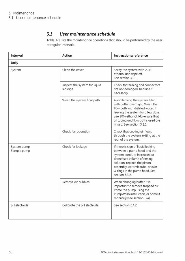
3.1 User maintenance scheduleTable 3-1 lists the maintenance operations that should be performed by the user at regular intervals.
Interval Action Instructions/reference
Daily
System Clean the cover Spray the system with 20% ethanol and wipe off. See section 3.2.1.
Inspect the system for liquid leakage
Check that tubing and connectors are not damaged. Replace if necessary.
Wash the system flow path Avoid leaving the system filled with buffer overnight. Wash the flow path with distilled water. If leaving the system for a few days, use 20% ethanol. Make sure that all tubing and flow paths used are rinsed. See section 3.2.1.
Check fan operation Check that cooling air flows through the system, exiting at the rear of the system.
System pumpSample pump
Check for leakage If there is sign of liquid leaking between a pump head and the system panel, or increased or decreased volume of rinsing solution, replace the piston assembly, ceramic tube, and/or O-rings in the pump head. See section 3.3.2.
Remove air bubbles When changing buffer, it is important to remove trapped air. Prime the pump using the PumpWash instruction, or prime it manually (see section 3.4).
pH electrode Calibrate the pH electrode See section 2.4.2
36 ÄKTApilot Instrument Handbook 18-1162-95 Edition AH

Maintenance 3
Pump rinsing solution Change rinsing solution Always use 20% ethanol as rinsing solution.
If the volume of rinsing solution in the storage bottles has increased, it can be an indication of internal pump leakage. Replace the piston assembly, ceramic tube, and/or O-rings in the pump head according to section 3.3.2.
If the volume of rinsing solution in the storage bottle has decreased significantly, check if the rinsing system connectors are mounted properly.
If the rinsing system connectors are not leaking, the piston, ceramic tube, and/or O-rings might be damaged. Replace according to section 3.3.2.
Every 3rd month
UV cell Check UV lamp run time See section 3.2.4
Mains cable Check the mains cable. If the cable is damaged, contact GE Healthcare service personnel.
Every 6th month
UV cell (or when required)
Clean the UV cell Clean the cell and the optical fiber connectors to ensure proper UV monitoring. See section 3.2.4.
Conductivity cell(or when required)
Clean the conductivity cell See section 3.2.6
pH electrode Check the pH electrode Check the pH electrode according to section 2.4.2. Replace the pH electrode if necessary. See section 3.3.9.
Interval Action Instructions/reference
ÄKTApilot Instrument Handbook 18-1162-95 Edition AH 37

3 Maintenance3.1 User maintenance schedule
Table 3-1. User maintenance schedule
Every year
UV cell Replace the O-rings See section 3.3.8
Mixer Replace the mixer chamber See section 3.3.3
Air inlet filter Contact GE service personnel.
When required
System pumpSample pump
Replace piston See section 3.3.2
Replace ceramic tube See section 3.3.2
Replace O-rings See section 3.3.2
Clean or replace the inlet and outlet check valves.
Clean the rinsing system check valve.
See section 3.2.2 and 3.3.2
pH electrode Clean the pH electrode See section 3.2.5
Valves Replace the membranes See section 3.3.4
Tubing connectors Replace the O-rings
TC connectors Replace the TC gaskets
Air trap Replace O-ring in vent connector
Interval Action Instructions/reference
38 ÄKTApilot Instrument Handbook 18-1162-95 Edition AH

Maintenance 3
3.2 User maintenance instructions
3.2.1 Cleaning the systemFor proper function, the system should be kept dry and clean. Chemical stains and dust should be removed.
1 Spray the system with 20% ethanol to remove stains and wipe off.
The column should be by-passed (tubing S6) during cleaning of the system flow path.
At the end of the dayIf the system will be used with the same buffers next day, rinse the pump and the system with distilled water as follows:
1 Submerge the appropriate inlet tubing in distilled water.
2 Replace the column with a by-pass tubing (S6).
3 Run the System Wash method found in the Method Wizard. This method flushes the entire system flow path, including selected inlet and outlet tubings.
Leaving the system for a few days1 Rinse the entire flow path with distilled water by, for example, using the
System Wash method as described in the previous section.
2 Repeat with a bacteriostatic solution, for example, 20% ethanol, having first removed the pH electrode (see instruction below).
The pH electrode should always be stored in a 1:1 mixture of pH 4 buffer and 2 M KNO3 when not in use. When the pH electrode is removed from the cell holder, the dummy electrode (supplied) must be inserted in the flow path.
CAUTION! Never leave the pH electrode in the cell holder when the system is not used, since this might cause the glass membrane of the electrode to dry out. Remove the pH electrode from the cell holder and fit the end cover filled with a 1:1 mixture of pH 4 buffer and 2 M KNO3. Do NOT store in water only.
ÄKTApilot Instrument Handbook 18-1162-95 Edition AH 39

3 Maintenance3.2 User maintenance instructions
Column cleaning – CIP ColumnColumns usually have flow rate and pressure limits that do not allow them to be cleaned with a normal cleaning procedure. CIP Column is a method specifically made for cleaning columns. The method is adapted to the column used when setting up the method in the Method Wizard, e.g. flow rate and pressure settings, column volume, etc.
Sanitization – CIP SystemCIP System is a method that can be used for sanitizing the entire system flow path. Flow rates, exposure times, etc. have been optimized thoroughly in order to reduce the amount of contaminants and thus meet cGMP demands. Due to the high flow rate during the CIP System run, the column must be replaced by a by-pass tubing before starting the method.
During the CIP System run, 1 M NaOH is flushed through the selected inlet tubing, through the tubing and components in the system flow path, and out through the outlet tubing.
3.2.2 System pump and sample pump
Cleaning the inlet and outlet check valvesFaulty operation of the check valves is usually indicated by irregular flow, very low flow or unstable pressure traces. Probable causes are air or dirt in a check valve preventing it from closing to seal and hold the pressure.
Record the pressure and identify the faulty check valve by observing the pressure trace (see section 4.9 Checking the pump pressure). The flow rate should not exceed 10 ml/min.
To clean the check valves in-place on the pump head:
1 Pump distilled water at 50 ml/min for 2 minutes. This also prevents precipitation of crystals.
2 Pump 100% methanol for approximately 10 minutes.
40 ÄKTApilot Instrument Handbook 18-1162-95 Edition AH

Maintenance 3
If this does not correct the problem, follow the instructions below for removing and then cleaning the valves.
Tools required: 16 mm torque wrench
Note: Flush the check valves with distilled water before removing them.
Note: Before removing the check valves, check that all input buffer bottles are placed below the level of the pump heads to prevent siphoning.
1 Disconnect and remove the tubing.
2 Use the 16 mm wrench to remove the valve from the pump head.
3 Use a syringe to flush distilled water through the valve to remove salt residues.
4 Immerse the complete valve in methanol and place in an ultrasonic bath for about 5 minutes.
Then repeat the treatment with distilled water.
5 Refit the check valves.
The inlet check valve is fitted to the lower side of the pump head. Tighten the valves using the torque wrench. See Fig. 3-2 for the tightening torque values.
6 Re-fit the tubing.
CAUTION! Handle the check valves with care when they have been removed from the pump heads to prevent loss of any internal components.
Down Up
Flow direction
CAUTION! Over-tightening might damage threads. Use a torque wrench to tighten the components.
ÄKTApilot Instrument Handbook 18-1162-95 Edition AH 41
WARNING! Incorrectly fitted tubing might loosen, causing a jet of liquid to spray out. This is especially dangerous if hazardous chemicals are in use. Connect the tubing by first inserting the tubing fully, then tightening the connector fingertight.

3 Maintenance3.2 User maintenance instructions
7 Prime the pump carefully and check that the pumping action has been corrected.
3.2.3 Membrane valvesIf a membrane does not close or open properly (activating the valve alarm) or if internal leakage appears, the valve might require cleaning.
To clean a membrane valve:
1 Pump 15 ml of 1 M NaOH at 10 ml/min through the pressure sensor either by using a pump or a syringe.
2 Leave it for 15 minutes.
3 Rinse thoroughly with 500 ml de-ionized water.
§If this does not correct the problem, follow the instructions in section 3.3.4 Valve block to dismount the membrane and clean the valve as follows:
1 Immerse the connection block and the membranes in methanol and place in an ultrasonic bath for about 5 minutes.
2 Repeat the treatment with distilled water.
3 Re-assemble the membrane valve.
CAUTION! Check valves have precision matched components and should only be disassembled further by a trained service engineer. If the problem cannot be corrected, the check valve should be replaced completely.
42 ÄKTApilot Instrument Handbook 18-1162-95 Edition AH

Maintenance 3
3.2.4 UV cell
Checking UV lamp run timeTo check the total run time of the UV lamp:
1 In System Control, select System:Maintenance...
2 Click the Info tab in the Maintenance Manager window.
3 Click on + next to System and then on + next to UV. The UV lamp run time (“on time”) is shown in the right-hand field.
Cleaning the UV cell in-line
A clean cell and optical connectors are essential for ensuring proper operation of the UV monitor.
Pump a cleaning or sanitizing agent through the cell. The standard recommendation is 1 M NaOH for 30 minutes. Then wash out with buffer.
Cleaning the UV cell off-line1 Flush a small amount of distilled water through the cell.
2 Connect a 10 ml syringe to the inlet of the cell and squirt distilled water through the cell in small amounts. Then fill the syringe with a 10% surface active detergent solution like Decon 90, Deconex 11, RBS 25 or equivalent, and squirt five times.
3 After five squirts, leave the detergent solution in the cell for at least 20 minutes.
4 Pump the remaining detergent solution through the cell.
5 Rinse the syringe and flush the cell with distilled water (30 ml).
Cleaning the optical fiber connectorsClean the fiber tips with 30% isopropanol using lens paper.
CAUTION! Do not allow solutions containing dissolved salts, proteins or other solid solutes to dry out in the cell. Do not allow particles to enter the cell as damage to the cell might occur.
WARNING! NaOH is corrosive and therefore dangerous to health. Avoid spillage and wear protective glasses.
CAUTION! Only use lens paper for touching the fiber tips.
ÄKTApilot Instrument Handbook 18-1162-95 Edition AH 43
3 Maintenance3.2 User maintenance instructions
3.2.5 pH electrode
Cleaning the pH electrodeNote: The pH electrode has a limited life length and should be replaced every six
months or when the response time is slow.
To improve the response, clean the electrode using one of the following procedures:
• Salt deposits: Dissolve the deposit by immersing the electrode first in 0.1 M HCl, then in 0.1 M NaOH, and again in 0.1 M HCl. Each immersion is for a five-minute period. Rinse the electrode tip in distilled water between each solution.
• Oil or grease films: Wash the electrode tip in a liquid detergent and water. If the film is known to be soluble in a particular organic solvent, wash with this solvent. Rinse the electrode tip in distilled water.
• Protein deposits: Dissolve the deposit by immersing the electrode in a solution containing 1% pepsin in 0.1 M HCl. After five minutes, rinse with distilled water.
If these procedures fail to improve the response, try the following procedure:
1 Heat a 1 M KNO3 solution to 60–80 °C.
2 Place the electrode tip in the heated KNO3 solution.
3 Allow the electrode to cool while immersed in the KNO3 solution before re-testing.
If these steps fail to improve the electrode, replace it.
pH electrode regenerationIf the electrode has dried out, immerse its lower end e in a 1:1 mixture of pH 4 buffer and 2 M KNO3 overnight.
CAUTION! Never leave the pH electrode in the cell when the system is not used, since this might cause the glass membrane of the electrode to dry out. Remove the pH electrode from the cell and fit the end cover filled with a 1:1 mixture of pH 4 buffer and 2 M KNO3. Do NOT store in water only.
WARNING! NaOH and HCl are corrosive and therefore dangerous to health. Avoid spillage and wear protective glasses.
44 ÄKTApilot Instrument Handbook 18-1162-95 Edition AH

Maintenance 3
3.2.6 Conductivity cell
If the conductivity measurements are not comparable to previous results, the electrodes in the conductivity cell might be contaminated and require cleaning.
To clean the cell:
1 Pump 15 ml of 1 M NaOH at 10 ml/min through the cell either by using a pump or a syringe.
2 Leave it for 15 minutes.
3 Rinse thoroughly with 500 ml de-ionized water.
Note: If the cell is totally blocked, the blockage can be broken by carefully using a needle or a piece of string.
3.2.7 Pressure sensors
If the pressure measurement seems to be inaccurate, the sensor might require cleaning.
To clean a pressure sensor:
1 Pump 15 ml of 1 M NaOH at 10 ml/min through the pressure sensor either by using a pump or a syringe.
2 Leave it for 15 minutes.
3 Rinse thoroughly with 500 ml de-ionized water.
If this does not correct the problem, dismount the pressure sensor according to the instructions in section 3.3.5 Pressure sensor (2-port or 3-port union) or 3.3.6 Pressure sensor (pump outlet manifold) and clean it as follows:
1 Immerse the tubing connection parts in methanol and place in an ultrasonic
WARNING! NaOH is corrosive and therefore dangerous to health. Avoid spillage and wear protective glasses.
WARNING! NaOH is corrosive and therefore dangerous to health. Avoid spillage and wear protective glasses.
ÄKTApilot Instrument Handbook 18-1162-95 Edition AH 45
bath for about 5 minutes.
2 Repeat the treatment with distilled water.
3 Re-assemble the pressure sensor.

3 Maintenance3.2 User maintenance instructions
3.2.8 Air sensors
If the air sensor does not react on air passing the sensor, it might require cleaning.
To clean an air sensor:
1 Pump 15 ml of 1 M NaOH at 10 ml/min through the air sensor either by using a pump or a syringe.
2 Leave it for 15 minutes.
3 Rinse thoroughly with 500 ml de-ionized water.
3.2.9 Air trap
To clean the air trap:
1 Fit a 5/16" stop plug in the outlet port.
2 Remove the vent connector at the top.
3 Connect a 5/16" connector with tubing at the top.
4 Fill the entire air trap with 1 M NaOH by using a pump or a syringe.
5 Leave it for 15 minutes.
6 Empty the air trap and rinse thoroughly with 1 l de-ionized water.
WARNING! NaOH is corrosive and therefore dangerous to health. Avoid spillage and wear protective glasses.
WARNING! NaOH is corrosive and therefore dangerous to health. Avoid spillage and wear protective glasses.
CAUTION! NaOH might cause the outer protection cylinder on the air trap to rupture. Avoid spillage.
Stop plug
5/16" nutwith tubing
46 ÄKTApilot Instrument Handbook 18-1162-95 Edition AH

Maintenance 3
3.3 Replacing spare parts
3.3.1 General instructionsSome of the components are attached to the separation unit by a snap connection. These components are detached by turning a quarter of a turn and pulling them off the panel. To attach a component, fit it in the connection and turn it a quarter of a turn until it snaps into position.
Note: Always make sure that the O-ring does not come loose when disconnecting a 5/16" connector. An O-ring that is stuck in the connector port might cause leakage when re-fitting the connector.
3.3.2 System pump P-907 and sample pump P-908If there are signs of liquid leaking between the pump head and the housing side panel, or the volume of the rinsing solution has increased or decreased, replace the piston assembly, liquid chamber and/or ceramic tube including O-rings of the leaking pump head.
Other typical symptoms of a damaged piston are observed as excessive piston wear, unstable pressure, a reduction in the flow or, in some cases, noise as the piston moves. The piston should be removed, examined for damage or salt precipitation and then replaced with a new piston if necessary.
If a damaged piston has been in operation, the ceramic tube might be damaged as well and should also be replaced.
If cleaning of a faulty check valve does not improve its performance, it should be replaced.
WARNING! Only use spare parts supplied or specified by GE.
O-ring
CAUTION! Do not disassemble the pump head unless there is good reason to believe that there is an internal leakage. Always make sure that sufficient spare components are available before attempting to replace a spare part.
ÄKTApilot Instrument Handbook 18-1162-95 Edition AH 47

3 Maintenance3.3 Replacing spare parts
Note: The power must be switched OFF when removing and refitting the pump heads.
Note: Always replace the piston on both pump heads at the same time.
Spare parts and tools required:
Seal kit containing (see Ordering information for code no.):– Piston assembly, 400 ml– Seal kit , 400 ml (includes O-rings and sealings)– Check valve, inner – Check valve, outer– Ceramic tube
– 3 mm Allen key– 16 mm wrench– 16 mm torque wrench– Screwdriver, flat-headed, with torque adapter
Note: Before disassembling the pump heads, move all input buffer bottles below the level of the pump heads to prevent siphoning.
Removing the old piston assembly1 Switch off the system with the mains power switch on the left-hand panel.
2 Remove the rinsing system tubing.
3 Remove the tubing connectors on the inlet and outlet check valves.
4 If the check valves are also to be checked/replaced, use the wrench to loosen the valves slightly. Do not remove them completely.
5 Using the Allen key, unscrew the two Allen screws locking the pump head in position. Loosen the screws cross-wise a half a turn at a time while pushing firmly on the front face of the pump head to compensate for the pressure of the piston return spring.
6 Carefully pull out the pump head and place it face down on the bench.
CAUTION! Read the following instructions carefully. Some individual parts of the pump head can be assembled incorrectly. Check the orientation of each part before continuing with the next instruction.
48 ÄKTApilot Instrument Handbook 18-1162-95 Edition AH

Maintenance 3
7 Using the flat-headed screwdriver, remove the two screws locking the piston assembly in position. Pull out the piston assembly.
8 Gently pull the ceramic tube off the piston.
9 Inspect the ceramic tube using a magnifying glass. Replace with a new ceramic tube if any scratches or cracks are found.
Fig 3-1. Pump head, exploded view
10 Inspect the piston, piston rod and return spring for signs of damage. If damaged, the piston assembly should be replaced.
11 Wipe the piston with a clean cloth. Inspect the piston with a magnifying glass for scratches. Replace the piston assembly if any scratches or cracks are found.
12 If salt solutions have been used, the piston rod or spring may be slightly corroded. This corrosion can be removed with a rubber eraser. If it cannot be wiped or rubbed clean, scrape off any deposits with a scalpel or razor blade.
Replacing the O-rings1 Carefully remove and discard the old rinse chamber O-ring.
2 Insert a new O-ring (thin).
3 Lift off the liquid chamber.
4 Carefully remove and discard the old pump head front O-ring.
5 Insert a new O-ring (thick).
Pump head front
Check valve,
O-ring (thick)
Liquidchamber
Ceramic tube
O-ring
Piston
Rinsechamber
Returnspring
Drainagehole
Piston assembly,
Piston rod
outer (inlet)
Check valve,outer (outlet)
inner (rinsing system)
(thin)
Check valve
Adapter
(underneath therinse chamber)
(Torque 8–10 Nm)
(Torque 8–10 Nm)
(Torque 3–3.5 Nm)
(Torque 2.5 Nm)
Screw (2 pcs.)(Torque 2.5 Nm)
400 ml
ÄKTApilot Instrument Handbook 18-1162-95 Edition AH 49

3 Maintenance3.3 Replacing spare parts
Replacing the outer check valves1 Unscrew the two loose check valves. Note the direction of the tubes inside
the valves. The flow always enters a tube through the round hole and exits through the triangular hole.
2 Inspect the nuts and the tubes for dirt or damage.
3 Replace with a new check valve if any dirt or damage is found and cleaning does not improve the performance of the old check valve (see section 3.2.2 System pump and sample pump).
Tighten the new check valve using the torque wrench. See Fig. 3-2 for the tightening torque value.
Replacing the inner check valve1 Use the two wrenches to remove the metal nut of the check valve from the
adapter. Note the direction of the tube inside the adapter; the round hole faces the rinse chamber.
2 Use a wrench to remove the adapter from the rinse chamber.
3 Inspect the nuts for dirt and damage. Replace the check valve and/or the adapter if required.
Tighten the new check valve and/or adapter using the torque wrench. See Fig. 3-2 for the tightening torque values.
Down Up
Flow direction
CAUTION! Over-tightening might damage threads. Use a torque wrench to tighten the components.
CAUTION! Over-tightening might damage threads. Use a torque wrench to tighten the components.
50 ÄKTApilot Instrument Handbook 18-1162-95 Edition AH

Maintenance 3
Assembling the new piston head
Fig 3-2. Pump head, exploded view
1 Make sure that the new O-rings are installed on the pump head front (thick O-ring) and the rinse chamber (thin O-ring).
2 With the pump head front facing downwards on the bench, place the liquid chamber onto the pump head front.
3 Carefully slide the ceramic tube onto the piston. Make sure that the tube end that has the largest bevel cutting on the inner edge faces the rinsing system chamber.
4 Insert the ceramic tube with the piston into the liquid chamber.
5 Use the two rinse chamber screws to lock the complete pump head together.
Tighten the screws using the screw driver with a torque adapter. See Fig. 3-2 for the tightening torque value.
Pump head front
Check valve,
O-ring (thick)
Liquidchamber
Ceramic tube
O-ring
Piston
Rinsechamber
Returnspring
Drainagehole
Piston assembly,
Piston rod
outer (inlet)
Check valve,outer (outlet)
inner (rinsing system)
(thin)
Check valve
Adapter
(underneath therinse chamber)
(Torque 8–10 Nm)
(Torque 8–10 Nm)
(Torque 3–3.5 Nm)
(Torque 2.5 Nm)
screw (2 pcs.)(Torque 2.5 Nm)
Rinse chamber
400 ml
Drainagehole
CAUTION! Over-tightening might damage threads. Use a torque wrench to tighten the components.
ÄKTApilot Instrument Handbook 18-1162-95 Edition AH 51
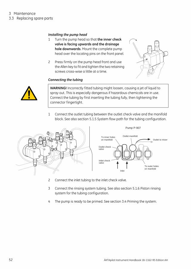
3 Maintenance3.3 Replacing spare parts
Installing the pump head1 Turn the pump head so that the inner check
valve is facing upwards and the drainage hole downwards. Mount the complete pump head over the locating pins on the front panel.
2 Press firmly on the pump head front and use the Allen key to fit and tighten the two retaining screws cross-wise a little at a time.
Connecting the tubing
1 Connect the outlet tubing between the outlet check valve and the manifold block. See also section 5.1.5 System flow path for the tubing configuration.
2 Connect the inlet tubing to the inlet check valve.
3 Connect the rinsing system tubing. See also section 5.1.6 Piston rinsing system for the tubing configuration.
4 The pump is ready to be primed. See section 3.4 Priming the system.
WARNING! Incorrectly fitted tubing might loosen, causing a jet of liquid to spray out. This is especially dangerous if hazardous chemicals are in use. Connect the tubing by first inserting the tubing fully, then tightening the connector fingertight.
Inlet
Outlet to mixer
Outlet manifold
Outlet checkvalve
Intlet checkvalve
Pump P-907
To outer holeson manifold
To inner holeson manifold
52 ÄKTApilot Instrument Handbook 18-1162-95 Edition AH

Maintenance 3
3.3.3 MixerSpare parts required:
– Mixer chamber, 5 ml (see Ordering information for code no.)– Stirrer bar (see Ordering information for code no.)
1 Make sure that the pumps are stopped.
2 Make sure that the buffer bottles are placed lower than the mixer to prevent draining.
3 Disconnect the tubing.
4 Open the plastic lock holding the mixer chamber. A spring secures the mixer chamber in position when the lock is opened.
5 Gently pull out the mixer chamber.
6 Insert the new mixer chamber with the flat side facing the front panel and close the lock.
7 Connect the tubing.
WARNING! When using hazardous chemicals, make sure that the used mixer chamber has been flushed with distilled water before removing it .
ÄKTApilot Instrument Handbook 18-1162-95 Edition AH 53

3 Maintenance3.3 Replacing spare parts
3.3.4 Valve block When replacing the wetted parts of a valve block, the connection block as well as all membranes should be replaced. At normal user maintenance, only the membranes need to be replaced.
Spare parts and tools required:
– Connection block (note that all connection blocks have separate code numbers, see Ordering information)
– Valve membrane containing 4 membranes (see Orderinginformation for code no.)
– 7 mm wrench
Removing the old connection block and membranes1 Flush the valve thoroughly with distilled water.
2 Empty the air trap, for example, through Waste2 in valve V5.
3 Disconnect all tubing from the valve.
4 Disconnect the UniNet-1 cable between the separation unit and the computer.
After approx. 1 min, the POWER LED on the front panel starts flashing slowly, which indicates that the communication between the computer and the separation unit is broken.
5 Remove the six attachment screws using the wrench.
6 Carefully loosen the old connection block.
54 ÄKTApilot Instrument Handbook 18-1162-95 Edition AH

Maintenance 3
7 Press the PAUSE and CONTINUE/RUN buttons on the front panel simultaneously for 3 seconds.
Note: This action is enabled only if the POWER LED flashes.
As a result, the membranes in all valves move to a position between open and closed (“service mode”), thus enabling their removal.
Fig 3-3. Valve block, exploded view
8 Pull out and discard the old membranes. Be careful not to scratch the mechanical housing of the valve!
Installing the new connection block and membranes:1 Fit the new membranes into position.
2 Press the PAUSE and CONTINUE/RUN buttons simultaneously for 3 seconds.
Check that the new membranes retract to the open position.
3 Carefully fasten the new connection block using the attachment screws.
Note: Make sure that the marking on the block is turned the right way round, i.e. not upside-down.
4 Connect the tubing.
5 Connect the UniNet cable between the separation unit and the computer.
6 When the connection between the computer and the separation unit is established, the valves take up their normal positions in End mode.
Connection block
Membrane
ÄKTApilot Instrument Handbook 18-1162-95 Edition AH 55

3 Maintenance3.3 Replacing spare parts
3.3.5 Pressure sensor (2-port or 3-port union)Spare parts and tools required:
– Pressure sensor, 2-port, or – Pressure sensor, 3-port (see Ordering information for code nos.)
– Screwdriver (small, flat-headed)
1 Flush the pressure sensor thoroughly with distilled water.
2 Switch off the system with the mains power switch.
3 Disconnect the tubing from the pressure sensor.
4 Loosen the locking screw at the lower side of the plastic holder using the small, flat-headed screwdriver.
5 Carefully pull out the pressure sensor from the holder.
6 Disconnect the signal cable from the pressure sensor.
7 Connect the signal cable to the new pressure sensor and insert it in the holder.
8 Tighten the locking screw.
9 Check the O-rings at the tubing ends and connect the tubing.
56 ÄKTApilot Instrument Handbook 18-1162-95 Edition AH
10 Calibrate the new pressure sensor according to section 2.4.1 Calibrating the pressure sensors.
To allow cleaning of the flow path inside the pressure sensor, loosen the four attachment screws at the rear of the sensor and remove the rear part.

Maintenance 3
3.3.6 Pressure sensor (pump outlet manifold)Spare parts and tools required:
– Pressure sensor incl. outlet manifold A (for P-907 and P-908)– Outlet manifold B (for P-907 only)
(see Ordering information for code nos.)
– 3 mm Allen key
1 Flush the outlet manifold thoroughly with distilled water.
2 Switch off the system with the mains power switch.
3 Disconnect all tubing from the outlet manifold.
4 Loosen the two attachment screws using the Allen key.
5 Gently pull out the outlet manifold.
6 Disconnect the signal cable.
7 Connect the cable to the new outlet manifold.
8 Fit the outlet manifold into position.
9 Carefully fasten the outlet manifold using the attachment screws. Tighten the screws cross-wise a little at a time.
10 Connect the tubing.
11 Calibrate the new pressure sensor according to section2.4.1 Calibrating the pressure sensors.
To allow cleaning of the flow path inside the
ÄKTApilot Instrument Handbook 18-1162-95 Edition AH 57
pressure sensor, loosen the four attachment screws at the rear of the sensor and remove the rear part.

3 Maintenance3.3 Replacing spare parts
3.3.7 Air sensorsSpare parts required:
– Air sensor Cell 940 (at sample inlet), or– Air sensor Cell 925 (at column inlet)
(see Ordering information for code nos.)
1 Flush the air sensor thoroughly with distilled water and stop the pump.
2 Switch off the system with the mains power switch.
3 Disconnect the tubing from the air sensor.
4 Release the air sensor holder from the panel by turning the holder a quarter of a turn.
5 Gently pull out the signal cable to reach the connector.
6 Disconnect the push-pull connector by pulling the sleeve and remove the air sensor.
7 Connect the cable from the new air sensor to the connector.
8 Fit the new air sensor in the holder.
9 Fasten the holder on the panel.
10 Connect the tubing.
Sleeve
58 ÄKTApilot Instrument Handbook 18-1162-95 Edition AH

Maintenance 3
3.3.8 UV cellSpare parts and tools required:
– UV cell 1/2/5 mm– O-ring kit (6 pcs.)– O-ring (1 pc.)– Shim plate 2 mm
(see Ordering information for code nos.)
– 3 mm Allen key– Phillips screw driver
Removing the UV cell1 Flush the cell with distilled water.
2 Switch off mains power to the system.
3 Disconnect the upper tubing from the UV cell.
4 Disconnect the optical fiber. The optical fiber is fragile and must be handled carefully!
5 Disconnect the TC clamp and the TC connector from the UV cell.
6 Loosen the two attachment screws to remove the UV cell from the front panel.
Installing the new UV cell1 Make sure that the correct optical path length is set on the new UV cell with
shim plates (see section Setting the optical path length).
2 Connect the TC connector to the lower port on the UV cell.
3 Fasten the UV cell to the panel using the attachment screws.
4 Connect the UV cell to the conductivity cell using the TC clamp.
Attachment screws
ÄKTApilot Instrument Handbook 18-1162-95 Edition AH 59
5 Connect the upper tubing to the UV cell.
6 Connect the optical fiber to the UV cell.
Make sure that the end with a knurled nut is connected to the UV cell.
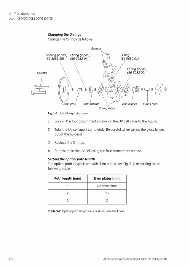
3 Maintenance3.3 Replacing spare parts
Changing the O-ringsChange the O-rings as follows:
Fig 3-4. UV cell, exploded view
1 Loosen the four attachment screws on the UV cell (refer to the figure).
2 Take the UV cell apart completely. Be careful when taking the glass lenses out of the holders!
3 Replace the O-rings.
4 Re-assemble the UV cell using the four attachment screws.
Setting the optical path lengthThe optical path length is set with shim plates (see Fig. 3-4) according to the following table:
Table 3-2. Optical path length versus shim plate thickness
O-ring (2 pcs.)
Glass lens Lens holder
Screws
Shim plates
Sealing (2 pcs.) (56-3081-98) (56-3082-04)
O-ring (2 pcs.)(56-3082-00)
O-ring(19-0680-01)
Glass lensLens holder
Screws
Path length [mm] Shim plates [mm]
1 No shim plate
2 0.5
5 2
60 ÄKTApilot Instrument Handbook 18-1162-95 Edition AH

Maintenance 3
3.3.9 pH electrodeSpare parts and tools required:
– pH electrode, ÄKTApilot– Cell holder, pH
(see Ordering information for code nos.)
– Phillips screwdriver
Replacing the pH electrode
1 Switch off the system with the mains power switch.
2 Unscrew the cable connector at the top of the old pH electrode.
3 Unscrew the locking nut that secures the pH electrode.
4 Remove the pH electrode.
5 Unpack the new pH electrode.
6 Remove the end cover. Make sure that it is not broken or dry.
7 Before using the electrode, immerse the glass tip in a pH 4 buffer solution for 30 minutes.
8 Carefully insert the electrode in the cell holder. Tighten the locking nut by hand to secure the electrode.
9 Fit the signal cable to the top of the pH electrode.
CAUTION! Handle the pH electrode with care. The tip of the pH electrode consists of a thin glass membrane. Protect it from breakage, contamination and drying out or the electrode will be destroyed. Always store the pH electrode with the end cover filled with a 1:1 mixture of pH 4 buffer and 2 M KNO3. Do NOT store in water only.
IN
ÄKTApilot Instrument Handbook 18-1162-95 Edition AH 61

3 Maintenance3.3 Replacing spare parts
Replacing the cell holder1 Flush the cell holder with distilled water.
2 Disconnect the tubing.
3 Disconnect the signal cable from the top of the pH electrode (if used).
4 Move the pH electrode or the dummy electrode to the new cell holder.
5 Remove the ground wire from the cell holder using the Phillips screwdriver.
6 Release the old cell holder from the panel by turning it a quarter of a turn.
7 Fasten the new cell holder on the panel.
8 Connect the tubing.
9 Connect the signal cable to the pH electrode (if used).
3.3.10 Conductivity cellSpare parts and tools required:
– Conductivity cell (see Ordering information for code no.)
1 Flush the cell with distilled water.
2 Switch off the system with the mains power switch.
3 Disconnect the tubing and the TC clamp.
4 Release the conductivity cell holder from the panel by turning it a quarter of a turn. Gently push down the cell before releasing if necessary.
5 Gently remove the old conductivity cell from the holder and disconnect the push-pull cable connector.
6 Move the TC union to the new conductivity cell.
7 Connect the cable to the new conductivity cell and put the cell in the holder. Make sure that the screw head end on the conductivity cell faces the pH electrode!
8 Connect the tubing and the TC clamp.
62 ÄKTApilot Instrument Handbook 18-1162-95 Edition AH

Maintenance 3
3.3.11 Air trapSpare parts and tools required:
– Air trap (see Ordering information for code no.)
– Phillips screwdriver
1 Flush the air trap thoroughly with distilled water.
2 Empty the air trap, for example, through Waste2 in valve V5.
3 Disconnect the tubing from the air trap.
4 Use the Phillips screwdriver to unscrew the screws that attach the air trap bracket to the separation unit panel.
5 Remove the old air trap by unscrewing the screws that attach the air trap to the bracket.
6 Attach the new air trap to the bracket.
7 Attach the bracket with the air trap to the separation unit panel.
8 Connect the tubing.
ÄKTApilot Instrument Handbook 18-1162-95 Edition AH 63

3 Maintenance3.4 Priming the system
3.4 Priming the system
3.4.1 Automated primingTo prime the pumps and the inlet tubing with buffer (or sample), use either of the pump wash instructions that are available in the System Control module:
• SystemPumpWash
• SamplePumpWash
3.4.2 Manual primingIf a pump wash instruction fails to fill the pump or tubing, the flow path in the pump might be dry, which reduces the pumping capacity. If so, the pump has to be primed manually using a syringe and appropriate fittings.
To prime the pump and inlet tubing manually:
1 Fill a flask with distilled water and immerse the appropriate inlet tubing in the water.
2 Connect a tubing equipped with 5/16" connectors at both ends to port 3 (Waste2) in the flow direction valve V5.
3 Connect a 5/16" female/M6 male union to the other end of the tubing.
4 Connect a M6 female/Luer female union to the first union.
5 Fit an empty male Luer syringe (> 25 ml) to the Luer union.
6 In the System Control module, select Manual:Flowpath.
7 Open the appropriate inlet valve and Waste2.
8 Use the syringe to draw water through the inlet tubing and pump until it starts to enter the syringe.
Fromport Waste2
5/16" female/M6 male union
M6 female/Luer female union
64 ÄKTApilot Instrument Handbook 18-1162-95 Edition AH

Troubleshooting 4
4 Troubleshooting
This chapter provides troubleshooting guidelines. The troubleshooting guide focuses on error symptoms related to monitor curves and operation of the individual components.
The chapter also contains instructions for running the Installation test, which is used for testing basic functions in the system.
If the suggested actions do not correct the fault, call GE Service.
4.1 UV curve
Monitor curve/Component Page
UV curve 65
Conductivity curve 66
Pressure curve 68
System pump and sample pump 69
Mixer 70
Membrane valves 70
Pressure sensors 71
Error symptom Possible cause Corrective action
Ghost peaks Dirt or residues in the flow path from previous runs
Clean the system according to section 3.2.1
Residues in the column from previous runs
Clean the column according to the column instructions
Poor mixing of the buffers Check that the mixer works correctly.
Check that the correct mixer chamber is being used. 5 ml is the default mixer chamber.
ÄKTApilot Instrument Handbook 18-1162-95 Edition AH 65

4 Troubleshooting4.2 Conductivity curve
4.2 Conductivity curve
Noisy UV-signal, signal drift or instability
Bad cable connections Check that the UV cell is properly attached to the panel
Bad UV fiber connections Check the connections of the UV cell optical fiber. Replace if necessary.
Dirty UV cell Clean the UV cell, refer to section 3.2.4
The buffer may be impure Check if the signal is still noisy with water
Error symptom Possible cause Corrective action
Error symptom Possible cause Corrective action
Baseline drift or noisy signal Leaking tubing connections Tighten the connectors. If necessary, replace the connectors.
Column not equilibrated Equilibrate the column. If necessary, clean the column.
Bad pump or mixer See sections 3.3.2 and 3.3.3
Dirty conductivity cell Clean the conductivity cell according to section 3.2.6
Waves on the gradient Bad pump function Check that the pump is operating and is programmed correctly
Bad mixer Check the motor operation. Place a finger on the mixer chamber and start it by starting the pump at a low flow rate. When the chamber is empty, you should both hear and feel the mixer motor and stirrer when they are spinning.
Conductivity measurement with Dirty conductivity cell Clean the conductivity cell
66 ÄKTApilot Instrument Handbook 18-1162-95 Edition AH
the same buffer appears to decrease over time
according to section 3.2.6
The ambient temperature may have decreased
Use a temperature compensation factor, see section 2.4.3
Ghost peaks appear in the gradient profile
Air bubbles passing through the conductivity cell
Check for loose tubing connections

Troubleshooting 4
Non-linear gradients or slow response to %B changes
Dirt in the tubing Make sure that the tubing has been washed properly
Bad pump function Check that the pump operates properly
Bad mixer Check the motor operation. Place a finger on the mixer chamber and start it by starting the pump at a low flow rate. When the chamber is empty, you should both hear and feel the mixer motor and stirrer when they are spinning.
Absolute conductivity value is wrong
Bad calibration Calibrate the conductivity cell, see section 2.4.3
Calibration solution, 1.00 M NaCl, not correctly prepared
Recalibrate using a new calibration solution
Incorrect or unstable reading Bad pump or membrane valve function
Check the pump and the valves
The temperature compensation not properly set
Check that the temperature sensor is calibrated, and that the correct temperature compensation factor is in use. See section 2.4.3.
The column not equilibrated Equilibrate the column. If necessary, clean the column.
Poor mixing Check the mixer by placing a finger on the mixer chamber and start it by starting the pump at a low flow rate. You should both feel and hear if the stirrer is rotating.
Error symptom Possible cause Corrective action
ÄKTApilot Instrument Handbook 18-1162-95 Edition AH 67

4 Troubleshooting4.3 Pressure curve
4.3 Pressure curve
Error symptom Possible cause Corrective action
Erratic flow, noisy baseline signal, irregular pressure trace
Air bubbles passing through or trapped in the pump
Check that there is sufficient buffer in the reservoirs
Check all connections for leaks
Inlet or outlet check valves not functioning correctly
Remove any dirt in the valves by cleaning according to section 3.2.2
Piston assembly leaking Replace the piston assembly, ceramic tube, and/or O-rings in the pump head. See section 3.3.2.
Blockage or partial blockage of flow path
Flush through to clear blockage
If necessary, replace tubing
68 ÄKTApilot Instrument Handbook 18-1162-95 Edition AH

Troubleshooting 4
4.4 System pump and sample pump
Error symptom Possible cause Corrective action
Liquid leaking between the pump head and the instrument panel
Piston, ceramic tube, liquid chamber or O-rings incorrectly fitted or worn
Replace the piston assembly, ceramic tube, and/or O-rings in the pump head. See section 3.3.2.
Low buffer flow and noise Bad piston spring Disassemble the pump head and examine the piston spring. Replace the piston assembly if necessary.
If the spring is corroded, check piston, ceramic tube, and/or O-rings. Make sure that the rinsing system is always used when working with aqueous buffers with high salt concentration.
If the piston is damaged, replace it according to section 3.3.2
Replace the piston assembly, ceramic tube, and/or O-rings with new components
Leakage around a tubing connector
Leaking connection and/or crystallized material around the tubing connector
Unscrew the connector and check if it is worn or incorrectly fitted. If required, replace the connector.Tighten the connector with your fingers only.
Erratic pump pressure Air trapped in the pump heads Check the pump function by observing the pressure curve in UNICORN. By observing the pressure trace, the pump head which is functioning abnormally can be identified.
Some examples of normal and abnormal pressure traces, together with comments, are shown in section 4.9.
Leaking connectors
Piston leakage
Piston damaged
Check valve malfunction
ÄKTApilot Instrument Handbook 18-1162-95 Edition AH 69

4 Troubleshooting4.5 Mixer
4.5 Mixer
4.6 Membrane valves
Error symptoms Possible causes Action
Leakage Leaking tubing connections Check the tubing connections. Re-tighten or replace if necessary
Check the mixer chamber. Replace if liquid has penetrated the mixer chamber walls and sealings.
Non-linear gradients or slow response to %B changes
Poor mixing of the buffers Check the mixer by placing a finger on the mixer chamber and start it by starting the pump at a low flow rate. You should both feel and hear if the stirrer is rotating. The mixer function can also be checked by running the installation test.
Error symptoms Possible causes Action
External leakage Leaking tubing connectors Check the tubing connectors. Tighten or replace if necessary.
Internal leakage (can be detected underneath the valve body)
The valve membrane might be worn or damaged
Change the valve membrane. See section 3.3.4.
High back-pressure Dirt in the flow path Clean the valve according to section 3.2.3
Change the valve membrane. See section 3.3.4.
Valve alarm The valve membrane has not returned to its normal position from the “service position”
Restart the systemm and UNICORN.
A valve membrane might be damaged
Change the valve membrane. See section 3.3.4.
70 ÄKTApilot Instrument Handbook 18-1162-95 Edition AH

Troubleshooting 4
4.7 Pressure sensors
4.8 Air sensors
4.9 Checking the pump pressureTo check the pump function, check the pressure curve in UNICORN.
There can be several causes of an abnormal pressure recording, for example:
• Air trapped in the pump heads.
• Leaking connections.
• Piston seal leakage.
• Check valve malfunction.
Error symptoms Possible causes Action
External leakage Leaking tubing connectors Check the tubing connectors. Tighten or replace if necessary.
High back-pressure Dirt in the flow path Clean the pressure sensor according to section 3.2.7
Change the pressure sensor. See section 3.3.5 or 3.3.6.
Error symptoms Possible causes Action
External leakage Leaking tubing connectors Check the tubing connectors. Tighten or replace if necessary.
High back-pressure Dirt in the flow path Clean the air sensor according to section 3.2.8
Change the pressure sensor. See section 3.3.7.
The system is immediately set to Pause when enabling the air sensor
The air sensor is filled with air Fill the air sensor with liquid before enabling
ÄKTApilot Instrument Handbook 18-1162-95 Edition AH 71
• Piston damaged.

4 Troubleshooting4.9 Checking the pump pressure
Some examples of abnormal pressure traces, together with comments, are shown in Table 4-1 .
Table 4-1. Abnormal pressure traces
Result Diagnosis
Left pump head OK, right pump head not working.Possible causes:• Bad piston. • Major leakage in inlet check
valve. • Inlet blocked.• Ceramic tube broken.
Air bubbles passing through pump heads
One pump head has stopped working. Possible causes:
• Major leakage in one pump head.
• Major leakage in inlet check valve.
• Inlet blocked.• Bad pump calibration.
Left LeftRight
72 ÄKTApilot Instrument Handbook 18-1162-95 Edition AH

Troubleshooting 4
4.10 Running the installation testThe installation test checks the function of the liquid delivery and the UV and conductivity monitoring system of ÄKTApilot. It can be used at any time to check the condition of the system.Correct gradient formation is tested by producing a linear gradient and a series of concentration steps of acetone. Correct UV monitoring is tested by monitoring the acetone concentration at 264, 254 and 280 nm and calculating the absorbance ratios 265/254 nm and 265/280 nm.
4.10.1 Testing pressure stabilityPerform a pressure test to establish that all air has disappeared from the pump heads. Proceed as follows:
1 Fit the dummy electrode in the pH cell holder.
2 Make sure the pump has been primed properly.
3 Make sure that inlet tubing InletA1 and InletB1 are immersed in a distilled water flask.
4 Connect the IN port on flow restrictor FR-902 to valve 6, port 3.
5 Connect the other port on FR-902 to valve 7, port 3.
6 Set the Columns flow path to Col1Bypass_Col2Down.
7 Run 100 ml/min at 0%B (distilled water). Check on the pump display that the pressure reading is stable (variation < ±5%).
8 Run 100 ml/min at 100%B (distilled water). Check on the pump display that the pressure reading is stable (variation < ±5%).
ÄKTApilot Instrument Handbook 18-1162-95 Edition AH 73
9 If the pressure is not stable, consult the section 4.4 System pump and sample pump for troubleshooting instructions.
10 Click on END.

4 Troubleshooting4.10 Running the installation test
4.10.2 Preparing the installation test
1 Prime the pumps with distilled water to remove any air trapped in the pump heads.
2 Prepare a flask containing 4.5 l of 0.4% acetone in 1 M NaCl.
3 Immerse inlet tubing InletA1 in a distilled water flask (> 2.5 l).
4 Immerse inlet tubing InletB1 in the acetone/NaCl flask.
5 Immerse inlet tubing Sample1 in the acetone/NaCl flask.
Note: FR-902 should remain in place between valve 6 and valve 7.
Note: The Installation Test starts with priming the inlet tubing with the test liquids.
4.10.3 Running the installation test1 Start UNICORN as described in section 2 Operation.
2 In UNICORN Main Menu, select File:Printer setup... Select the appropriate printer from the list and select Landscape. Click OK to acknowledge the chosen printer.
3 Click on the Instant Run button and then Run to start the Method Wizard.
4 Check the Special Method button and select Installation Test.
5 Click Run.
6 Click Next to go through the subsequent pages and make the appropriate selections.
Note: Check the InstPilot option in the Evaluation Procedures page to print the installation result automatically after the test.
7 Click START to start the Installation Test.
Installation Test Method Guide
Buffer Sample1: 0.4% acetone in 1 M NaCl
Buffer InletA1 Distilled water
Buffer InletB1 0.4% acetone in 1 M NaCl
Test flow rate 100 ml/min
Test run time Approximately 25 minutes
74 ÄKTApilot Instrument Handbook 18-1162-95 Edition AH

Troubleshooting 4
To customize the Curves view pane in System Control:
1 Right-click in the Curves window and select Properties.
2 Click the Curves tab.
3 Select the following curves to be displayed:
• UV_265nm
• UV_254nm
• UV_280nm
• Cond
• Conc
4 Click OK.
The curves are shown on the screen as the test progresses. The installation test method run time is approximately 25 minutes.
Note: The inlet Sample2 will be opened at the end of the run to flush out the salt solution. It can be avoided by changing this method instruction to Sample1.
5 When the test is finished, the printer automatically prints the chromatogram and the test result (if InstPilot in Evaluation Procedures has been selected).
Gradient result Step response result
100%95%
70%
30%
5%
0%
Sample pumpresponse
ÄKTApilot Instrument Handbook 18-1162-95 Edition AH 75

4 Troubleshooting4.10 Running the installation test
4.10.4 Evaluating the installation test results
Automatic evaluationThe system automatically prints the test result when the test is finished. The print-out consists of a chromatogram and an evaluation of the test result.
• If the gradient test result is OK, the print-out says “Gradient linearity accepted”.
• If the step response test result is OK, the print-out says “Step response accepted”.
• If the UV response test result is OK, the print-out says “UV response accepted”.
If any of the evaluated values fall outside the specified range, go to section 4.10.5 Correcting faulty evaluation results.
Manual evaluationIf you suspect that the automatic evaluation does not give a reliable result, a manual evaluation can be done.
1 In UNICORN Main menu click on in the Results window.
2 Double-click on the Installation Test icon to open the result file.
3 Maximize the chromatogram window by clicking on in the upper right corner.
4 Right-click in the Curves view pane and select Properties.
5 Click on the Curves tab and select:
• Installation Test01:1_UV1_265nm@01,SMTH
• Installation Test01:1_UV1_254nm@02,SMTH
• Installation Test01:1_UV1_280nm@03,SMTH
• Installation Test01:1_Conc
6 Click OK.
7 Right-click in the chromatogram window, and select Marker.
76 ÄKTApilot Instrument Handbook 18-1162-95 Edition AH
8 Make sure that the UV1 curve value is displayed.

Troubleshooting 4
9 Read the absorbance for the steps corresponding to Installation Test01:1_UV1_265nm@01,SMTH. Move the vertical bar to the constant section of each plateau by dragging it . Enter the absorbance values (in mAU) in column 2 in the Step response table in section 4.10.6, leaving out the decimals.
10 Read the absorbance for the plateaus corresponding to 0% and 100% B for the curves (click on the curve name to change the curve reading):
• Installation Test01:1_UV1_265nm@01,SMTH
• Installation Test01:1_UV1_254nm@02,SMTH
• Installation Test01:1_UV1_280nm@03,SMTH
Enter the values in column 2 in the UV response table in section 4.10.6.
11 Click on Print under File to print the chromatogram.
Evaluating the gradientPlace a ruler along the gradient part of curve Installation Test01:1_UV1_265nm@01,SMTH in the printed report.
The curve should be linear between 10% B and 90% B and void of discontinuities.
Evaluating the step responseCalculate the relative absorption plateau heights for curve Installation Test01:1_UV1_265nm@01,SMTH as follows:
1 Subtract the baseline value (0% B) from each of the values in column 2 in the Step response table in section 4.10.6 and enter the results in column 3.
2 Divide each value in column 3 by the baseline corrected value corresponding to 100% B, multiply by 100 and enter the results in column 4.
The values in column 4 should all fall within the intervals given in column 5.
ÄKTApilot Instrument Handbook 18-1162-95 Edition AH 77

4 Troubleshooting4.10 Running the installation test
Evaluating the UV responseCalculate the UV response ratios in the following way:
• Subtract the baseline values (0% B) corresponding to each UV curve from the values in column 2 of the UV response table in section 4.10.6 and enter the results in column 3.
• Calculate the absorbance ratios 265/254 nm and 265/280 nm using the values of column 3 and enter the results in column 4.
The ratios obtained should fall within the intervals given in column 5.
Evaluating the sample pump functionThe 100% step response of the three UV curves (265 nm, 280 nm and 254 nm) and the conductivity curve should not differ more than ±5% from the corresponding sample pump response.
4.10.5 Correcting faulty evaluation results Should any of the evaluated values fall outside the specified range, proceed as follows:
If the system differs from the standard configuration, evaluate the result manually.
If the faulty evaluation result remains, continue below.
Faulty gradient• The mixer is faulty.
• Disturbances – may arise from air in the pump, pump valves or bad sealings in the pump. Refer to the section 4.4 System pump and sample pump.
Faulty step response• If all values are faulty – air in the pump or a faulty pump.
• 5% and 95% faulty – bad sealing in the pumps (5% faulty = pump module B, 95% faulty = pump module A).
Faulty sample pump functionIf values are faulty, make sure that the sample pump is properly primed and that
78 ÄKTApilot Instrument Handbook 18-1162-95 Edition AH
all tubing fittings are tightened properly.
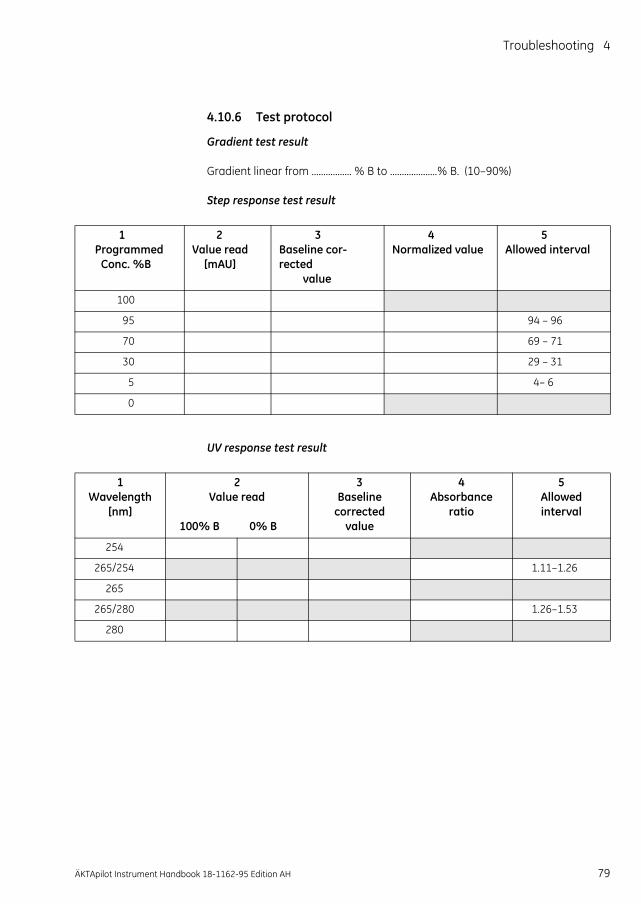
Troubleshooting 4
4.10.6 Test protocol
Gradient test result
Gradient linear from ................. % B to ....................% B. (10–90%)
Step response test result
UV response test result
1 Programmed
Conc. %B
2Value read
[mAU]
3Baseline cor-rected
value
4Normalized value
5Allowed interval
100
95 94 – 96
70 69 – 71
30 29 – 31
5 4– 6
0
1 Wavelength
[nm]
2Value read
100% B 0% B
3Baseline
correctedvalue
4Absorbance
ratio
5Allowedinterval
254
265/254 1.11–1.26
265
265/280 1.26–1.53
280
ÄKTApilot Instrument Handbook 18-1162-95 Edition AH 79

4 Troubleshooting4.10 Running the installation test
80 ÄKTApilot Instrument Handbook 18-1162-95 Edition AH

Reference information 5
5 Reference information
5.1 System description
5.1.1 ÄKTApilot systemÄKTApilot is a high performance, automated liquid chromatography system. ÄKTApilot consists of a separation unit and a Windows-based computer running UNICORN version 4.11 or higher.
The system is designed for process development, process scale-up and scale-down, and small scale production. It can be used with pre-packed columns as well as with standard laboratory and pilot-scale columns packed with media. It can also be used for packing columns.
ÄKTApilot is biocompatible, hygienic and sanitizable. It meets all GLP and cGMP requirements for Phase I–III in drug development and final-scale production.
Fig 5-1. ÄKTApilot system
ÄKTApilot Instrument Handbook 18-1162-95 Edition AH 81

5 Reference information5.1 System description
5.1.2 Indicators and controls on the separation unitThe separation unit is equipped with the following indicators, switch and push-buttons:
Table 5-1. Indicators, switches and push-buttons on the separation unit.
Using the CONTINUE/RUN and PAUSE push-buttons to set the system in ”Service mode” (the valve membranes move to a position between open and closed):
1 Disconnect the UniNet-1 cable between the separation unit and the computer. Wait for the POWER indicator to start flashing slowly (after approx. 1 min).
2 Press CONTINUE/RUN and PAUSE simultaneously for 3 seconds.
Indicator/Switch/Push-button
Color Description
POWER
(switch)
– Switches on/off power to the system.
Located on the left panel.
POWER
(indicator)
Green Flashes rapidly for a few seconds during the internal communication test in the separation unit when switching on power to the unit .
Flashes slowly when the communication test is finished.
Steady light when UNICORN is connected to the separation unit.
CONTINUE/RUN
(push-button/indicator)
Green Pressing this button with the system in Pause mode, causes the pump to continue at the set flow rate and gradient values.
The button is lit in Run mode.
PAUSE
(push-button/indicator)
Yellow Pressing this button, stops the pump but retains the set flow rate and gradient values. All inlet and outlet valves are closed.
The button is lit in Pause mode.
Alarm buzzer – Indicates an alarm in UNICORN. Located behind the front panel.
AB
82 ÄKTApilot Instrument Handbook 18-1162-95 Edition AH

Reference information 5
5.1.3 Component locationThe location of each of the main components of ÄKTApilot separation unit is shown in the following figure. The rinsing system tubing is not included.
Fig 5-2. Location of the ÄKTApilot components
Mixer
Air sensor 2
Sample pump
System pump,module A and B
Outlet valve V8
UV cell
Conductivity cell
pH electrode
Column valve V7
Pressure sensor 3
Pressure sensor 1
Flow direction valve V5
Air trap valve V4
Column valve V6
3-port union with pressure sensor 4
2-port union with
Air sensor 1
Air trap
Sample valve V3 Inlet valve V1 Inlet valve V2
Outlet valve V9
ÄKTApilot Instrument Handbook 18-1162-95 Edition AH 83

5 Reference information5.1 System description
5.1.4 Electrical connectionsMains cable
Fig 5-3. Mains cables
The mains cable is permanently connected inside the separation unit and routed through a conduit entry in the rear panel for connection to a mains outlet.
The cable wires are marked and connected as shown in Table 5-2 .
Table 5-2. Cable wires
Analog IN Analog out UniNet 1 Digital I/O
Mains
FansInternal I/O Press2 Press1 Valves Air 2 Air 1
Tomains outlet
ÄKTApilot
Computer
WARNING! HIGH VOLTAGE. The mains cable must only be connected and changed by authorized service personnel. Faulty connection might result in live system parts that can give a lethal electric shock.
Wire marking Connected to
Yellow/green Ground
L1 Live
L2 Neutral
84 ÄKTApilot Instrument Handbook 18-1162-95 Edition AH

Reference information 5
Analog I/O and digital I/O
Fig 5-4. Controller upper rear panel
The upper rear panel on the controller inside the separation unit is equipped with three D-Sub connectors – Analog IN, Analog out and Digital I/O – intended for signals to/from auxiliary equipment.
• Digital I/O (D-Sub, 9-pole, female)
Analog IN Analog out UniNet 1 Digital I/O
Mains
FansInternal I/O Press2 Press1 Valves Air 2 Air 1
Userconnectors
Internalconnectors
WARNING! HIGH VOLTAGE. The rear panel should only be accessed by authorized service personnel. Faulty connection might result in live system parts that can give a lethal electric shock.
Pin Signal Remark1
1 Section 5.3.1 Technical specifications provides a full specification of the Digital I/O interface.
1 Positive input 1 Active level > 4.5 V between pin 1 and 2Inactive level < 2.5 V between pin 1 and 2Impedance: ~900 ohmMax. 25 V
2 Negative input 1
3 Positive input 2 Active level > 4.5 V between pin 3 and 4Inactive level < 2.5 V between pin 3 and 4Impedance: ~900 ohmMax. 25 V
4 Negative input 2
5 Reference ground
6 Output 1 On/off relay between pin 6 and 7 Max. 100 mA. Max. 25 V.
7 Output 1
8 Output 2 On/off relay between pin 8 and 9 Max. 100 mA. Max. 25 V.
9 Output 2
12345
6789
ÄKTApilot Instrument Handbook 18-1162-95 Edition AH 85

5 Reference information5.1 System description
• Analog IN (D-Sub, 9-pole, male)
• Analog OUT (D-Sub, 9-pole, female)
The reference ground pins within the connectors are common. Reference grounds between the connectors as well as to the chassis and internal grounds are separated.
The signal interfaces are opto-isolated.
Pin Signal Remark1
1 Section 5.3.1 Technical specifications provides a full specification of the Analog In interface.
1–6 Reference ground
7 Negative input
8 Positive input 0–20 mA or ±5 V (selectable)
9 Reference ground
Pin Signal Remark1
1 Section 5.3.1 Technical specifications provides a full specification of the Analog Out interface.
1–2 Reference ground
3 Positive output 4–20 mA
4–6 Reference ground
7 Negative output
8–9 Reference ground
1 2 3 4 5
6 7 8 9
12345
6789
86 ÄKTApilot Instrument Handbook 18-1162-95 Edition AH

Reference information 5
pH electrode and conductivity cell
Fig 5-5. Controller mid rear panel
The sockets for the electrical signals to/from the pH electrode and the conductivity cell are located on the mid rear panel on the controller inside the separation unit.
Conductivity Flow Cell UniNet 1
Mains
pH-Ground pH-Probe
I 0
WARNING! HIGH VOLTAGE. The rear panel should only be accessed by authorized service personnel. Faulty connection might result in live system parts that can give a lethal electric shock.
Connector Function
pH-Ground Ground from the pH flow cell housing
pH-Probe Signal cable from the pH electrode
Conductivity Flow Cell Connection cable to the conductivity cell.D-Sub, 9-pole, female
ÄKTApilot Instrument Handbook 18-1162-95 Edition AH 87

5 Reference information5.1 System description
5.1.5 System flow pathThe following flow diagram shows the positions of the components and tubing in the ÄKTApilot liquid flow path.
Fig 5-6. Liquid flow path
Waste
2
Syst
em p
ump
P-90
7A
B
Mix
er
Inle
tva
lve
(V1)
Col
umn
valv
e(V
7)
Sam
ple
valv
e (V
3)
Waste
F1
UV CO
ND
12
34
A1A2
A3A4
12
34
B1B2
B3B4
13
4
14
Sam
ple
pum
pP-
908
1 2 3 4
13
4
87
65
12
34
Sample 1
Air t
rap
valv
e(V
4)
Inle
tva
lve
(V2)
Flow
dire
ctio
nva
lve
(V5)
Col
umn
valv
e(V
6)
Air
sens
or (1
)
Air
sens
or(2
)
Out
let
valv
e(V
8)
Out
let
valv
e(V
9)
Pres
sure
sens
or (2
)
Pres
sure
sens
or (1
)Pr
essu
rese
nsor
(3)
Pres
sure
sens
or (4
)
pH
Fracti
onco
llecti
on
S7/S
8
43
21
S2S1
0
S1
S2
S3S3
S2
S1S3
S3S3
S3S5
S5S13
S3
S6S4
S4
S4
S4
S13 S6
(2x)
S6 (2
x)S6
(2x)
S7
TC/T
CS4
On-
line
filte
r(o
ptio
nal)
Air t
rap
S8 S8
S6S6
Sample 2Sample 3Sample 4
88 ÄKTApilot Instrument Handbook 18-1162-95 Edition AH

Reference information 5
Table 5-3. Tubing description (continues on the next page)
Tubing Length [mm] i.d. [mm] Material LocationFrom To
S1 85 2.9 ETFE Pressure sensor 4 pH cell holder (IN)
pH cell holder (OUT) Conductivity cell (lower)
S2 120 2.9 ETFE Valve V4 (upper port) Air sensor 1
Valve V8 (right port) Valve V9 (left port)
Pressure sensor 2 Valve V5 (upper port)
S3 200 2.9 ETFE Valve V1 (left port) P-907 A (left, lower)
Valve V1 (right port) P-907 A (right, lower)
Valve V2 (left port) P-907 B (left , lower)
Valve V2 (right port) P-907 B (right, lower)
Pressure sensor 1 (inner ring, upper)
Mixer (IN)
Pressure sensor 1 (outer ring, upper)
Mixer (IN)
Mixer (OUT) Valve V4 (lower port)
S4 300 2.9 ETFE Valve V6 (port 4) Pressure sensor 4
Valve V7 (port 4) Pressure sensor 4
UV cell (upper) Valve V8 (left port)
Valve V5 (port 4) Valve V6 (left port)
Valve V5 (port 1) Valve V7 (left port)
S5 350 2.9 ETFE Valve V3 (left port) P-908 (left head, lower)
Valve V3 (right port) P-908 (right head, lower)
S6 400 2.9 ETFE P-907 A (left , upper) Pressure sensor 1 (inner ring, lower, left)
P-907 A (right, upper) Pressure sensor 1 (inner ring, lower, right)
P-907 B (left , upper) Pressure sensor 1 (outer ring, lower, left)
P-907 B (right, upper) Pressure sensor 1 (outer ring, lower, right)
P-908 (left, upper) Pressure sensor 3 (lower, left)
P-908 (right, upper) Pressure sensor 3 (lower, right)
Air trap (OUT) Valve V4 (port 4)
Valve V6 (port 1), by-pass Valve V7 (port 1)
Valve V6 (port 3), by-pass Valve V7 (port 3)
ÄKTApilot Instrument Handbook 18-1162-95 Edition AH 89

5 Reference information5.1 System description
Table 5-4. Tubing description (continued)
The tubings S1–S8 are pre-flanged. Each tubing end is equipped with a UNF 5/16" male connector and a perfluororubber O-ring.
A selection of unions and connectors is included on delivery. It contains TC connectors, M6 connectors, UNF 5/16" connectors, and unions. They can be used with various types of column fittings and for connecting the inlet and outlet tubing.
Optional tubing configurationTubing with i.d. 1.6 mm can be used in the system flow path instead of the i.d. 2.9 mm tubing in order to enhance system performance at low flow rates. See Ordering information for code numbers of i.d. 1.6 mm tubing and connectors.
Note: When using i.d 1.6 mm tubing, the system flow path might not be sanitizable.
Tubing Length [mm] i.d. [mm] Material LocationFrom To
S7 2000 2.9 ETFE Valve V5 (port 3) Waste 2
Valve V9 (port 1) Waste F1
S8 1200 2.9 ETFE Valves V9, V8 (ports 2–8)
Fraction collection
Valve V6 (port 1) Column
Valve V7 (port 1) Column
S10 95 2.9 ETFE Air sensor 1 Pressure sensor 2
S13 470 2.9 ETFE Valve V4 (port 1) Air trap (IN)
Pressure sensor 3 (OUT, upper)
Valve V5 (port 2)
90 ÄKTApilot Instrument Handbook 18-1162-95 Edition AH

Reference information 5
5.1.6 Piston rinsing systemThe piston rinsing system tubing is connected to the rearmost holes on the pump heads. The following flow diagram and table show the tubing configuration of the piston rinsing system.
Fig 5-7. Piston rinsing system
Note: Use the holders on the left panel intended for the containers.
Table 5-5. Tubing description (piston rinsing system)
Note: To eliminate the risk of re-introducing bacteria, etc. always use a separate waste container. Do not recirculate the same rinsing solution! Note also that a small amount of fluid remains in the pump and this comes into
System pump P-907
A B
Sample pump P-908
Rinsingsolution
Rinsingsolution
Waste Waste
Optionalpath
Optionalpath
S7
S7
S5
S7
S12
S5 S1
S7
S4
S5
S12
3-port 2
3-port 1
Tubing Length [mm] i.d. [mm] Material LocationFrom To
S1 85 2.9 ETFE 3-port union 2 P-907 A (right, upper)
S4 200 2.9 ETFE 3-port union 2 P-907 B (right, upper)
S5 350 2.9 ETFE P-908 (left head, upper) P-908 (right head, lower)
P-907 A (left , upper) P-907 A (right, lower)
P-907 B (left , upper) P-907 B (right, lower)
S7 2000 2.9 ETFE Rinsing solution container P-908 (left head, lower)
P-908 (right head, upper) Waste (or back to the rinsing solution container
Rinsing solution container 3-port union 1
3-port union 2 Waste (or back to the rinsing solution container
S12 150 2.9 ETFE 3-port union 1 P-907 A (left, lower)
3-port union 1 P-907 B (left , lower)
ÄKTApilot Instrument Handbook 18-1162-95 Edition AH 91

5 Reference information5.1 System description
contact with fluid on the other side of the pump.
5.1.7 Column tubing, inlet tubing, and outlet tubingThis section contains information on the column tubings, inlet tubings, and outlet tubings that are included in the ÄKTApilot system delivery. It also describes the additional tubing components needed to fully equip the system.
Column tubing kit
One complete Column tubing kit is included at delivery. Additional kits can be ordered (see Ordering information).
Item Component Code No. Quantity/pack
Number of packs included at delivery
1 Tubing S8 1200 mm 18-1169-75 1 2
2 Connector TC 5/16" female 18-1169-22 2 2
3 TC-Gasket 25/4 mm 18-1169-24 2 1
4 Union M6 female 5/16" female 18-1169-17 2 2
5 Union M6 female 5/16" male 18-1169-16 2 1
2
1
3 4 5
92 ÄKTApilot Instrument Handbook 18-1162-95 Edition AH

Reference information 5
Inlet tubing
The following inlet tubings are included at delivery:
• One complete Tubing with sanitary fitting (items 1-4)
• Two complete Elbow 90° TC25-6, long (items 4 and 5)
Item Component Code No. Quantity/pack
Aditional number of packs to fully equip the inlets
1 Tubing with sanitary pre-flanged fitting TC25i.d. 6 mm, L=125 cm, PVC
18-0005-44 1 11
2 Clamp TC25 18-1169-18 4 2
3 Elbow 90° TC25-6, PP 18-1169-19 1 10
4 TC-Gasket 25/6.5 mm 18-1169-25 4 5
5 Elbow 90° TC25-6, long, PP 18-1169-20 2 5
1
2
3
4
4
4
5
ÄKTApilot Instrument Handbook 18-1162-95 Edition AH 93
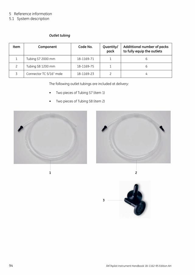
5 Reference information5.1 System description
Outlet tubing
The following outlet tubings are included at delivery:
• Two pieces of Tubing S7 (item 1)
• Two pieces of Tubing S8 (item 2)
Item Component Code No. Quantity/pack
Addittional number of packs to fully equip the outlets
1 Tubing S7 2000 mm 18-1169-71 1 6
2 Tubing S8 1200 mm 18-1169-75 1 6
3 Connector TC 5/16” male 18-1169-23 2 4
1 2
3
94 ÄKTApilot Instrument Handbook 18-1162-95 Edition AH

Reference information 5
5.2 Component descriptionThis section describes the components in the liquid flow path of the ÄKTApilot separation unit.
5.2.1 Pump P-907 and P-908Pump P-907 and P-908 are high performance laboratory and pilot-scale pumps for use in liquid chromatography where accurately controlled liquid flow is required.
A buffer in an external vessel is drawn in by the action of the pump. Twin reciprocating pump heads then work in unison to deliver a smooth, low-pulsation flow from the pump outlet manifold.
P-907 is used as system pump; P-908 as sample pump.
Pump P-907 and P-908 features:
• Pressure range: 0–2 MPa (20 bar, 290 psi).
• Flow rate range: 4–400 ml/min in isocratic and gradient mode. Double mode flow rate range: Up to 800 ml/min. The gradient performance is limited above 400 ml/min.
• P-907 is equipped with 2 pump modules; A and B, with two pump heads each. This permits binary gradients.
• Each pump houses a pressure sensor in the outlet manifold.
• Low pulsation.
Pump headP-907 consists of two pump modules, A and B. P-908 has only one pump module. Each pump module consists of two pump heads. The individual heads are identical but are actuated in opposite phase to each other by individual stepper motors controlled by a microprocessor. This gives a continuous, low pulsation liquid delivery.
Each pump head is equipped with an inlet check valve and an outlet check valve for the liquid flow. In addition, each pump head has an outlet check valve for the rinsing system flow.
ÄKTApilot Instrument Handbook 18-1162-95 Edition AH 95

5 Reference information5.2 Component description
Solvent is drawn up into the pump head through a non-return inlet check valve by the action of the piston being withdrawn from the pump chamber.
On the delivery stroke of the piston, the inlet check valve is sealed by the pressure developed and buffer is forced out through a similar check valve at the outlet.
Fig 5-8. Pump head, exploded view
The pistons are actuated by cams (eccentrics) driven by the motors. Force for the retraction of the pistons is provided by coil springs. The length of stroke of the pistons is fixed and changes in the flow rate are made by varying the speed of the drive motor.
Inlet
Outlet to mixer
Outlet manifold
Outlet checkvalve
Intlet checkvalve
Pump P-907
To outer holeson manifold
To inner holeson manifold
Pump head front
Outletcheck valve
Inletcheck valve
O-ring
Liquidchamber
Ceramictube
O-ring
Rinsing systemcheck valve
Piston
Rinsechamber
Returnspring
Drainagehole
96 ÄKTApilot Instrument Handbook 18-1162-95 Edition AH
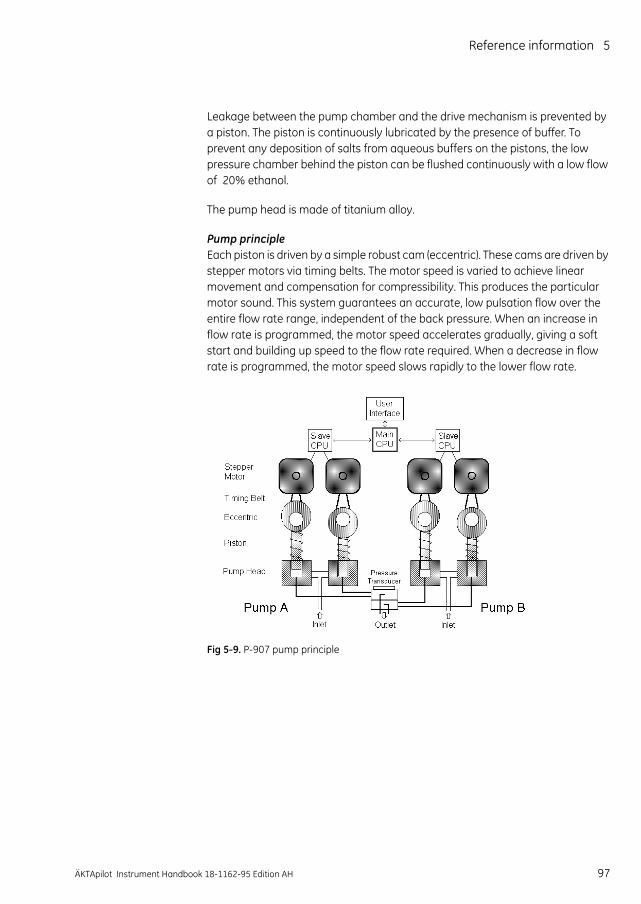
Reference information 5
Leakage between the pump chamber and the drive mechanism is prevented by a piston. The piston is continuously lubricated by the presence of buffer. To prevent any deposition of salts from aqueous buffers on the pistons, the low pressure chamber behind the piston can be flushed continuously with a low flow of 20% ethanol.
The pump head is made of titanium alloy.
Pump principleEach piston is driven by a simple robust cam (eccentric). These cams are driven by stepper motors via timing belts. The motor speed is varied to achieve linear movement and compensation for compressibility. This produces the particular motor sound. This system guarantees an accurate, low pulsation flow over the entire flow rate range, independent of the back pressure. When an increase in flow rate is programmed, the motor speed accelerates gradually, giving a soft start and building up speed to the flow rate required. When a decrease in flow rate is programmed, the motor speed slows rapidly to the lower flow rate.
Fig 5-9. P-907 pump principle
ÄKTApilot Instrument Handbook 18-1162-95 Edition AH 97
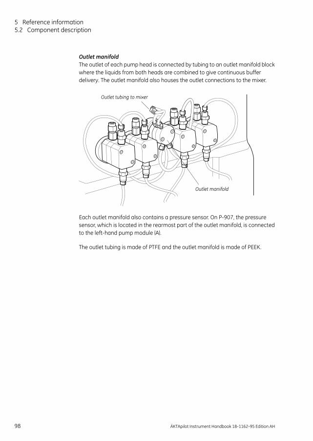
5 Reference information5.2 Component description
Outlet manifoldThe outlet of each pump head is connected by tubing to an outlet manifold block where the liquids from both heads are combined to give continuous buffer delivery. The outlet manifold also houses the outlet connections to the mixer.
Each outlet manifold also contains a pressure sensor. On P-907, the pressure sensor, which is located in the rearmost part of the outlet manifold, is connected to the left-hand pump module (A).
The outlet tubing is made of PTFE and the outlet manifold is made of PEEK.
Outlet tubing to mixer
Outlet manifold
98 ÄKTApilot Instrument Handbook 18-1162-95 Edition AH

Reference information 5
5.2.2 Membrane valveThe system uses stepper motor-actuated membrane valves for controlling the liquid flow in the separation unit. The valves in the system are located in nine valve blocks.
A valve block consist of a connection block containing the ports and the membranes, and a mechanical housing containing the stepper motors, cams and actuating pistons.
The membrane in a valve is actuated by a stepper motor via a cam and a piston. The piston is attached to a rubber membrane which is either retracted from or pressed against the valve seat. Consequently, the membrane either opens or closes the valve. An electrical switch indicates if the valve is open or closed. No power is required to keep the valve in the open or closed position.
The valve seats have two different diameters. The smaller valve seats are used in valves where the operating pressure is higher than in other parts of the system.
The connection block is made of PEEK and the membranes of FFKM (perfluororubber). The connection block and the membranes are replaceable.
Valve block typesThere are six different types of membrane valve blocks. The following illustrations show the flow path in the valve blocks and where the valves are located. The illustrations also show whether the valves are normally open (NO) or closed (NC).
• Inlet valve V1 and V2 and sample valve V3
In V1, V2 and V3, only one valve in a block can be open at a time.
Tosystem pump/sample pump
From buffer /sample containers
21 3 4
Tosystem pump/sample pump
NC NC NC NC
ÄKTApilot Instrument Handbook 18-1162-95 Edition AH 99

5 Reference information5.2 Component description
• Air trap valve V4
• Flow direction valve V5
• Column valve V6 and V7
• Outlet valve V8
• Outlet valve V9
Frommixer
1 4Toair sensor 1
To air trap From airtrap (on-line filter)
NC NC
Tovalve V6
From sample pump
34 2 1
Frompressure sensor 2
Towaste
Tovalve V7
NC NCNO NO
Fromvalve V5
From/To columns
1 3 4
Topressure sensor 4
NC NC NO
FromUV cell
To fraction collection/waste
78 6 5
Tovalve V9
NC NC NC NC
Fromvalve V8
To fraction collection/waste
34 2 1
NC NC NC NC
100 ÄKTApilot Instrument Handbook 18-1162-95 Edition AH

Reference information 5
The table below shows the size of the valve seats in the valve blocks.
Table 5-6. Valve seat sizes
The valve blocks have UNF 5/16" female ports except for the inlets on valve V1–V3, which have G 1/8" female inlet ports.
5.2.3 Mixer M-905The mixer is a dynamic, single-chamber mixer positioned directly after the outlet manifold of system pump P-907.
A mixer motor behind the ÄKTApilot front panel spins a magnet at 600 rpm, which causes the stirrer in the mixing chamber to rotate.
The system comes with a 5 ml mixer chamber, which is replaceable. The wetted part in the chamber is made of PEEK. The stirrer is coated with PTFE.
5.2.4 pH electrode and cell holderThe pH electrode is optimized for continuous pH measurement in the ÄKTApilot flow path. The electrode is of the sealed combination double junction type. It contains a sealed Ag/AgCl reference, which cannot be refilled, an internal electrolyte bridge of 4 M KCl saturated with Ag/AgCl, an outer electrolyte bridge of 1 M KNO3, an annular ceramic reference junction and a low profile pH membrane.
The pH electrode has a glass tip and the cell holder is made of titanium. The whole assembly is replaceable.
Valve block Valve seat size
V1–V3, V5, V8, V9 Large
V4, V6, V7 Small
ÄKTApilot Instrument Handbook 18-1162-95 Edition AH 101
The pH electrode should be calibrated regularly. This procedure is described in section 2.4.2 Calibrating the pH electrode.

5 Reference information5.2 Component description
5.2.5 Monitor UV-901 and UV cellThe UV cell is designed for continuous measurement of UV absorbance. The UV monitoring system provides high performance detection for wavelengths between 190 and 700 nm. Three wavelengths can be detected simultaneously. The optical pathlength – 1, 2 or 5 mm – is set with shim plates.The default length is 2mm.
The UV cell housing is made of PEEK, other wetted parts are made of glass and titanium.
Monitor principleA xenon flash lamp gives a high intensity, continuous spectrum throughout the range 160–2000 nm. The light enters a monochromator which includes a condensing system, blocking filter, entrance slit and a concave aberration-corrected holographic grating. Monochromatic light from the grating is directed to an optical fibre. The grating is turned by a stepping motor.
For wavelengths between 360–700 nm, a blocking filter is moved into the light path to filter out unwanted light, of a half wavelength from the second order spectrum, before entering the monochromator.
Fig 5-10. UV monitor principle
Detectorsand electronics
Flash lamp 100 Hz
Monochromator
Beamsplitter
S
R
Con-densor
Blockfilter
UV cell
102 ÄKTApilot Instrument Handbook 18-1162-95 Edition AH

Reference information 5
The light passing from the monochromator to the cell and from the cell to the detector electronics is guided by optical fibers which focus its full intensity on the liquid flow path, maximizing the sensitivity of the monitoring. Before entering the cell, the monochromatic light is split in a beam splitter, with 50% of the light passing through the sample fibre (S) and the cell, and 50% being directed through the reference fiber (R). Two photodiodes with identical characteristics monitor the intensities of the measuring and reference beams.
The detection system is very stable since the optical unit is located away from the lamp and electronics so that noise and drift caused by temperature variations is avoided.
At calibration, the instrument automatically finds 2 persistent lines in the spectrum of xenon. The wavelengths of these known lines are used to calibrate the stepper motor that turns the grating.
Note: Using two or three wavelengths results in increased wear on the monochromator mechanics. To reduce the required maintenance use only one wavelength if this is sufficient for the application.
5.2.6 Conductivity cellThe cell has two cylindrical titanium electrodes positioned in the flow path of the cell. An alternating voltage is applied between the electrodes and the resulting current is measured and used to calculate the conductivity of the buffer. The system controls the AC frequency and increases it with increasing conductivity between 50 Hz and 50 kHz, giving maximum linearity and true conductivity values.
The conductivity is automatically calculated by multiplying the measured conductance by the cell constant of the cell. The cell constant is pre-calibrated on delivery but can be measured with a separate calibration procedure. This procedure is described in section 2.4.3 Calibrating the conductivity cell.
One of the electrodes has a small temperature sensor for measuring the temperature of the buffer in the cell. Temperature variations
Eluent
Temperature sensor
ÄKTApilot Instrument Handbook 18-1162-95 Edition AH 103
influence the conductivity and in some applications, when very precise conductivity values are required, it is possible to program a temperature compensation factor that recalculates the conductivity to a set reference temperature.
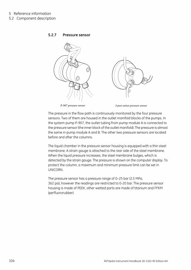
5 Reference information5.2 Component description
5.2.7 Pressure sensor
The pressure in the flow path is continuously monitored by the four pressure sensors. Two of them are housed in the outlet manifold blocks of the pumps. In the system pump P-907, the outlet tubing from pump module A is connected to the pressure sensor (the inner block of the outlet manifold). The pressure is almost the same in pump module A and B. The other two pressure sensors are located before and after the columns.
The liquid chamber in the pressure sensor housing is equipped with a thin steel membrane. A strain gauge is attached to the rear side of the steel membrane. When the liquid pressure increases, the steel membrane bulges, which is detected by the strain gauge. The pressure is shown on the computer display. To protect the column, a maximum and minimum pressure limit can be set in UNICORN.
The pressure sensor has a pressure range of 0–25 bar (2.5 MPa, 362 psi), however the readings are restricted to 0-20 bar. The pressure sensor housing is made of PEEK, other wetted parts are made of titanium and FFKM (perfluororubber).
P-907 pressure sensor 3-port union pressure sensor
104 ÄKTApilot Instrument Handbook 18-1162-95 Edition AH

Reference information 5
5.2.8 Air trapThe liquid flow in the separation unit can be routed through an air trap in order to remove air from the liquid. Preventing air from entering the column is important since air might reduce the chromatographic performance of the column.
Through the air trap valve V4, the flow is routed to the inlet port at the bottom of the air trap. The flow enters the air trap cylinder through a pipe which reaches about 3 cm above the bottom of the cylinder. The air in the liquid is trapped in the cylinder while the liquid exits the cylinder through a hole at the bottom. The liquid then continues through the outlet port back to the V4 (or to the optional on-line filter).
The air trap also has an air vent connector at the top, which is used for adjusting the liquid level in the air trap to suit the flow rate that is used.
The air trap volume is 81 ml, and the max. pressure limit 2 MPa. The air trap cylinder is made of glass, the bottom and top parts are made of polypropylene, and the outer protective tube is made of polycarbonate.
5.2.9 Air sensor 925 and 940The air sensor is a high precision monitor designed for continuous monitoring of air bubbles in the flow path. The air sensor is made of PEEK.
There are two different air sensors in the systems; one for sample application and one for column protection. When air is detected, the system is either paused, or performs an action that is set in the method.
The air sensor 940 used for sample application should be connected on the sample inlet tubing between a selected inlet valve (V1, V2 or V3) and the sample vessel. The air sensor is used to detect when the sample vessel is emptied, and to protect the column from air bubbles. The flow path in this air sensor has i.d. 4 mm.
The air sensor 925 used for column protection is connected before the columns. It is important to protect the column from air since air might damage the packed medium or cause poor chromatographic performance. The flow path in this air sensor has i.d. 2.5 mm.
ÄKTApilot Instrument Handbook 18-1162-95 Edition AH 105

5 Reference information5.2 Component description
5.2.10 Online Filter (optional)The optional online filter comes in two different kits, Sartorius (18-1171-06) and Millipore (18-1173-45).The following is recommended with regards suitable filters to the filter kits:
5.2.11 Frac 950 (optional)Fraction collector Frac-950 (18-6083-00) is an automated fraction collector for use in liquid chromatography as part of an ÄKTAdesign chromatography system. Its design allows x-y fractionation but without x-y movements.
Frac-950 is equipped with an accumulator to eliminate spillage at high flows. A drop sensor that can be used to control tube changes at low flows is also included.
Frac-950 is delivered with Rack A (18-6083-11) which contains the following vessels:
120 x 18 mm tubes8 x 30 mm tubes
Different types of racks accommodating different sizes and types of tubes are available as options. Accessories for collecting extra large fraction volumes are also available.
Frac-950 has a maximum flow rate of 100 ml/min and a fraction size of 0.1 - 99999.99 ml in Volume mode and 0.1 - 99999.99 min in Time mode.
Filter Kit Cartridge Connection
Sartorius Minicartridge Size 7
Connector 15
Millipore Millidisk 10 Code M
Sartorius filter kit
106 ÄKTApilot Instrument Handbook 18-1162-95 Edition AH

Reference information 5
5.3 Specifications
5.3.1 Technical specifications
ÄKTApilot separation unit
Mains voltage 100–240 V~, 50–60 Hz
Power consumption 800 VA
Fuse specification min. T 10A L (SB) up to max. T 16A L (SB) on external mains supply(no user-replaceable fuse in the separation unit)
Degree of protection IP 24
Dimensions, separation unit 900 × 750 × 540 mm (H × W × D)
Weight, separation unit 114 kg (monitor arm not included)
System hold-up volume 32 ml (from one of the pump head inlets on the system pump to valve V9, port 8)
System Frac-delay volume 3.5 ml (from the UV flow cell to valve V9, port 2)
Ambient temperatureoperationstorage
+4 - +40 °C-25 - +60 °C
Relative humidity, operation 20%–95% for temperatures up to 31°C decreasing linearly to 50% relative himidity at 40 °C
Cabinet material Stainless steel 304
Digital outputprotection
max. voltage
2 channels (opto-isolated relays)Automatic reset fuse, max. current 140 mA25 V between output pins, and between outputs and chassis ground
Digital inputactive level passive level impedance max. voltage
2 channels (opto-isolated)> 4.5 V< 2.5 V~ 900 ohm25 V between input pins, and between inputs and chassis ground
ÄKTApilot Instrument Handbook 18-1162-95 Edition AH 107

5 Reference information5.3 Specifications
Analog outputprotection
rangeresolutionaccuracymax. voltage
Opto-isolated Automatic reset fuse, max. current 50 mA4–20 mA0.001 mA0.2%25 V between output pins and chassis ground
Analog inputvoltage mode
rangeaccuracyimpedance
current moderangeaccuracyimpedance
max. voltage
Opto-isolated
±0–5 V (max. ±25 V)0.15% of full scale1 Mohm
0–20 mA (max. 50 mA)0.2%250 ohm25 V between input pins and chassis ground or reference ground
Compliance with standards The declaration of conformity is valid for the instrument only if it is:
• used in laboratory locations
• used in the same state as it was delivered from GE except for alterations described in the user documentation
• connected to other CE labelled GE Healthcare modules or other products as recommended
Safety standards This product meets the requirement of the Low Voltage Directive (LVD) 73/23/EEC through the following harmonized standards:
• EN 610101-1
• IEC 61010-1
• CAN/CSA-C22.2 No. 61010-1
• UL61010-1
108 ÄKTApilot Instrument Handbook 18-1162-95 Edition AH

Reference information 5
Computer and monitorSee the specifications provided by the manufacturer of the computer and monitor.
System pump P-907 and sample pump P-908
EMC standards This instrument meets the requirements of the EMC Directive 89/336/EEC through the following harmonized standards:
• EN 61326 (emission and immunity)
• EN 55011, GR 1, Class A (emission)
• This instrument complies with part 15 of the FCC rules (emission). Operation is subject to the following two conditions:
1 This instrument may not cause harmful interference.
2 This instrument must accept any interference received, including interference that may cause undesired operation.
Flow rateisocratic and gradient modedouble mode
4–400 ml/minUp to 800 ml/min (for gradient specification, see below)
Increment 0.1 ml
Pressure 0–2 MPa (20 bar, 290 psi)
Flow rate accuracy < ±2% (4–400 ml/min, 0.1–2 MPa)
Flow rate reproducibility rsd < 0.5% (4–400 ml/min, 0.1–2 MPa)
Viscosity Max. 5 cP
Gradient compositionaccuracyreproducibility
±3% rsd < 0.5% (8–400 ml/min, 10–90% linear gradient, 5–95% step gradient
Internal volumemaximum volumeminimum volume
1760 µl/pump head615 µl/pump head
ÄKTApilot Instrument Handbook 18-1162-95 Edition AH 109

5 Reference information5.3 Specifications
UV measurement, Monitor UV-901
Mixer M-905
UV cell path length 1/2/5 mm
Internal volume 300 µl
Max. pressure 2 MPa (20 bar, 290 psi)
Wavelength accuracy ±2 nm
Wavelength precision ±0.01 nm
Noise 1,2
Single wavelengthshort-term (0.5–1 min)long-term (1–10 min)
Dual wavelengthsshort-term (0.5–1 min)
long-term (1–10 min)
1 Measured with water at 150 ml/min, time constant 1s, 2 mm UV cell path length2 Typical values at room temperature after warm-up.
< 6 × 10⁻⁵ AU at 230 nm< 6 × 10⁻⁵ AU at 230 nm
< 2 × 10⁻⁴ AU at 230 nm and 254 nm< 2 × 10⁻⁴ AU at 230 nm and 254 nm
Linearity < 2% deviation up to 2 AU at 280 nm (iron(III)-sulphate in 0.1 M sulphuric acid)
Drift 2 < 4 × 10⁻⁴ AU/hour at 230 nm
Absorbance range 0.001–3.5 AU
Max. flow rate 800 ml/min
Max. pressure 2.5 MPa (25 bar, 362 psi)
Internal volume 4.2 ml
Mixing principle Chamber with a stirrer bar
110 ÄKTApilot Instrument Handbook 18-1162-95 Edition AH

Reference information 5
pH measurement, Monitor pH/C-901
Conductivity measurement, Monitor pH/C-901
pH range 0–14 (spec. valid between 2 and 12)
Accuracytemperature compensatednot temperature compensated
±0.1 pH units within 4–40 ºC±0.2 pH units within 15–25 ºC±0.5 pH units within 4–15 ºC and 25–40 °C
Response time Max. 10 s (0–95% of step)
Long-term drift Max. 0.1 pH units/10 h
Flow rate sensitivity Max. 0.1 pH units within 0-100 ml/min.
Max. pressure 0.5 MPa (5 bar, 72 psi)
Internal volume, pH cell holder 240 µl
Conductivity range 1 µS/cm to 999.9 mS/cm
Deviation from theoretical conductivity Max. ±2% of full scale calibrated range or ±10 µS/cm whichever is greater in the range 1 µS/cm to 300 mS/cm
Reproducibilityshort-termlong-term
Max. ±1% or ±5 µS/cmMax. ±3% or ±15 µS/cm
Noise Max. ±0.5% of full scale calibrated range
Response time Max. 3 s (0–95% of step)
Temperature sensoraccuracydrift
±2.0 °C±0.5 °C per 10 h
Flow rate sensitivity ±1% within 0–400 ml/min
Max. flow rate 800 ml/min
Max. pressure 2 MPa (20 bar, 290 psi)
Internal volume, conductivity cell 180 µl
ÄKTApilot Instrument Handbook 18-1162-95 Edition AH 111

5 Reference information5.3 Specifications
Membrane valve
Pressure sensor
Air sensor 925 and 940
Max. pressure 2.2 MPa (22 bar, 320 psi)
Back-pressure 0.015 MPa at 400 ml/min
Valve principle Stepper motor-controlled membranes
Pump oulet manifolds
Pressure range 0–2.5 MPa
Offset error < 0.02 MPa
Accuracy < ±2% (FSD)
Internal volume 202 µl
2-port and 3-port union
Pressure range 0–2.5 MPa
Offset error < 0.005 MPa
Accuracy < ±2% (FSD)
Internal volume2-port union3-port union
331 µl346 µl
Max. flow rate 800 ml/min
Max. pressureCell 925Cell 940
2.5 MPa (25 bar, 362 psi)2.5 MPa (25 bar, 362 psi)
Internal volumeCell 925Cell 940
190 µl480 µl
112 ÄKTApilot Instrument Handbook 18-1162-95 Edition AH

Reference information 5
Tubing connections
Note: The i.d. 2.9, o.d. 3/16" tubing can be replaced by i.d. 1.6 mm, o.d. 1/8" tubing (sanitizability not guaranteed).
Liquid feed requirements
Table 5-7. ÄKTApilot technical specifications
Inlet A1–A4 (V1)Inlet B1–B4 (V2)Sample 1–4 (V3)
dimension (i.d.,o.d.)flange type/size
6.0 mm, 9.8 mmTC 25
Outlet F2–F8 (V8, V9)dimension (i.d.,o.d.)flange type/size
2.9 mm, 3/16"UNF 5/16"
WasteF1 (V9)dimension (i.d.,o.d.)flange type/size
2.9 mm, 3/16"UNF 5/16"
Waste2 (V5)dimension (i.d.,o.d.)flange type/size
2.9 mm, 3/16"UNF 5/16"
Column 1, Column 2 (V6, V7)dimension (i.d.,o.d.)flange type/size
2.9 mm, 3/16"UNF 5/16"
Internal tubing connections between inlet and outlet
dimension (i.d.,o.d.)flange type/size
2.9 mm, 3/16" UNF 5/16"
Media feed requirements
Inlet -1 – 0 m height difference 1
1 Valid for water. If using liquids with higher density or higher viscosity than water, the distance will decrease.
Outlet 0 – 1 m height difference 1
Pump wash feed requirements
Inlet +0-1 m height difference 1
Outlet +0-1 m height difference 1
ÄKTApilot Instrument Handbook 18-1162-95 Edition AH 113

5 Reference information5.3 Specifications
5.3.2 System performance specifications
Table 5-8. ÄKTApilot performance specifications
System flow rateisocratic and gradient flowdouble mode
4–400 ml/minUp to 800 ml/min (limited gradient performance above 400 ml/min)
Operating pressure Up to 2 MPa (20 bar, 290 psi) between system pump and column inlet
UV wavelength range 190–700 nm in steps of 1 nm, 3 wavelengths simultaneously
pH range 0–14 (spec. valid between 2 and 12)
Conductivity range 1 µS/cm to 999.9 mS/cm
System back-pressuresystem pump – V6, port 4V6, port 4 – V9, port 1
0.060 MPa at 400 ml/min0.045 MPa at 400 ml/min
114 ÄKTApilot Instrument Handbook 18-1162-95 Edition AH

Reference information 5
5.3.3 ÄKTApilot component materialsThe wetted materials of ÄKTApilot are listed below:
Table 5-9. Wetted materials in ÄKTApilot
FFKM = perfluororubber (PFR91 Resel 77045)CTFE = chlorotrifluoroethylene (KelF81)PEEK = polyetheretherketone (PEEK 450G)PTFE = polytetrafluoroethylene ETFE = ethylenetetrafluoroethylenePP = polypropyleneUHMWPE = ultrahigh molecular weight polyethyleneSuprasil = quartz
PEEK PTFE FFKM ETFE CTFE PP UHMWPE
Titanium
Boro-silicate(glass) Ceramic Suprasil 2 Elgiloy
Ruby/sapphire
System pumpSample pump
X X X X X X X X
UV cell X X X X
pH cell holder/dummy electrode
X X X
Conductivity cell X X
Mixer X X
Membrane valve X X
Air trap X X X X
Pressure sensors X X X
Air sensors X
Tubing X X
Unions/Connectors
X X X
ÄKTApilot Instrument Handbook 18-1162-95 Edition AH 115

5 Reference information5.4 Chemical resistance guide and chemical compatibility
5.4 Chemical resistance guide and chemical compati-bility
The chemical resistance of ÄKTApilot to some of the most commonly used chemicals in liquid chromatography is indicated in the table below. The ratings are based on the following assumptions:
1 The synergistic effects of chemical mixtures have not been taken into account.
2 Room temperature and limited over-pressure is assumed.
Note: Chemical influences are time and pressure dependent. Unless otherwise stated, all concentrations are 100%.
Chemical Exposure< 1 day
Exposureup to 2 months
Comments
Acetaldehyde OK OKAcetic acid, < 5% OK OKAcetic acid, 70% OK OKAcetonitrile OK OK FFKM, PP and PE swellAcetone, 10% OK Avoid PVDF is affected by long-term useAmmonia, 30% OK OK Silicone is affected by long-term useAmmonium chloride OK OKAmmonium bicarbonate OK OKAmmonium nitrate OK OKAmmonium sulphate OK OK1-Butanol OK OK2-Butanol OK OKCitric acid OK OKChloroform OK Avoid ECTFE, CTFE, PP and PE are affected by
long-term useCyclohexane OK OKDetergents OK OKDimethyl sulphoxide Avoid Avoid PVDF is affected by long-term use1, 4-Dioxane Avoid Avoid ETFE, PP, PE and PVDF are affected by
long-term useEthanol OK OKEthyl acetate OK Avoid Silicone not resistant
Pressure limit for PEEK decreasesEthylene glycol OK OKFormic acid OK OK Silicone not resistantGlycerol OK OKGuanidinium hydrochloride OK OK
116 ÄKTApilot Instrument Handbook 18-1162-95 Edition AH

Reference information 5
Hexane OK Avoid Silicone not resistantPressure limit for PEEK decreases
Hydrochloric acid, 0.1 M OK OK Silicone not resistantHydrochloric acid, > 0.1 M OK Avoid Silicone not resistant
Titanium is affected by long-term useIsopropanol OK OKMethanol OK OKNitric acid, diluted OK Avoid Silicone not resistantNitric acid, 30% Avoid Avoid Elgiloy is affected by long-term usePhosphoric acid, 10% OK Avoid Titanium, aluminium oxide and glass
are affected by long-term usePotassium carbonate OK OKPotassium chloride OK OKPyridine Avoid Avoid ETFE, PP and PE not resistantSodium acetate OK OKSodium bicarbonate OK OKSodium bisulphate OK OKSodium borate OK OKSodium carbonate OK OKSodium chloride OK OKSodium hydroxide, 2 M OK Avoid PVDF and borosilicate glass are
affected by long-term useSodium sulphate OK OKSulphuric acid, diluted OK Avoid PEEK and titanium are affected by
long-term useSulphuric acid, medium
concentrationAvoid Avoid
Tetrachloroethylene Avoid Avoid Silicone, PP and PE are not resistantTetrahydrofuran Avoid Avoid ETFE, CTFE, PP and PE are not resistantToluene OK Avoid Pressure limit for PEEK decreasesTrichloroacetic acid, 1% OK OKTrifluoroacetic acid, 1% OK OKUrea OK OKo-Xylenep-Xylene
OK Avoid PP and PE are affected by long-term use
Chemical Exposure< 1 day
Exposureup to 2 months
Comments
ÄKTApilot Instrument Handbook 18-1162-95 Edition AH 117

5 Reference information5.5 Ordering information
5.5 Ordering informationA selection of inlet and outlet tubing and connectors are included in the delivery of ÄKTApilot. The items listed in below are accessories and spare parts that can be ordered from your local GE representative.
Item Quantity/pack
Code no.
System pump/ Sample pump
Pump head 400 ml cpl., including piston assembly, O-rings (2 pcs.), ceramic tube, liquid chamber, pump head front, 3 check valves
1 29-0310-81
Piston assembly, 400 ml, cpl., including rinsing chamber, piston, sealing, O-ring, check valve adapter
1 18-1169-90
Ceramic tube 1 29-0239-78
Check valve, inner, cpl. 1 18-1169-88
Check valve outer, cpl. 1 18-1169-89
Seal kit, 400 ml 1 18-1169-91
pH monitoring
pH electrode, ÄKTApilot, includingO-ring and nut
1 18-1168-77
Cell holder, pH 1 18-1170-02
Dummy pH electrode, including O-ring and nut
1 18-1169-11
O-ring 1 18-1118-60
Conductivity monitoring
Conductivity cell, i.d. 2.5 mm 1 18-1169-00
Cell holder, air sensor/cond 1 18-1170-01
UV monitoring
UV cell, 1/2/5 mm 1 18-1168-83
Shim plate, 2 mm 2 18-1168-84
O-ring kit 6 18-1134-88
O-ring 10 19-0680-01
Optical fiber 1 18-1170-17
Mixer
Mixer chamber, 5 ml, 5/16" 1 18-1168-98
Stirrer, diam. 15.7 mm 1 18-1114-32
118 ÄKTApilot Instrument Handbook 18-1162-95 Edition AH

Reference information 5
Air sensors
Cell-925 1 18-1167-70
Cell-940 1 18-1159-54
Connector TC–G1/8", PEEK (for Cell-940)
2 18-1171-02
Air trap
Air trap, complete 1 18-1170-97
Membrane valve
Connection block V1 1 18-1169-01
Connection block V2 1 18-1169-02
Connection block V3 1 18-1169-03
Connection block V4 1 18-1169-04
Connection block V5 1 18-1169-05
Connection block V6 1 18-1169-06
Connection block V7 1 18-1169-07
Connection block V8 1 18-1169-08
Connection block V9 1 18-1169-09
Valve membrane 1 18-1169-10
Inlet connectors, short/long, PEEK (for inlet valves)
4(2+2)
18-1170-16
Elbow 90° TC 25–6, PP 1 18-1169-19
Elbow 90° TC 25–6, long, PP 2 18-1169-20
Inlet connection kit , incl. M27 nut, washer and circlip (for Elbow 90°)
4 18-1169-21
Elbow 90° kit, including inlet connection kit, Elbow 90° and TC gasket 25/6.5
1 18-1170-60
Pressure sensors
Pressure sensor, 2.5 MPa, including outlet manifold A (for P-907 and P-908)
1 18-1169-79
Outlet manifold B (for P-907 only) 1 18-1169-86
Pressure sensor, 2-port 1 18-1169-78
Pressure sensor, 3-port 1 18-1170-19
Connectors and unions
Union M6 female–UNF 5/16" male, PEEK 2 18-1169-16
Union M6 female–UNF 5/16" female, PEEK 2 18-1169-17
Item Quantity/pack
Code no.
ÄKTApilot Instrument Handbook 18-1162-95 Edition AH 119

5 Reference information5.5 Ordering information
Connector TC–5/16" female, PEEK 2 18-1169-22
Connector TC–5/16" male, PEEK 2 18-1169-23
Connector TC–5/16" male, short, PEEK 2 18-1170-08
Connector 5/16" female–5/16" female, PEEK 2 18-1173-51
Clamp TC 25 4 18-1169-18
TC gasket 25/4 mm, FFKM 4 18-1169-24
TC gasket 25/6.5 mm, FFKM 4 18-1169-25
Tubing connector for 3/16" o.d. tubing, PEEK
10 18-1112-49
Ferrules for 3/16" o.d. tubing, PEEK 10 18-1112-48
Union Luer female/M6 female, polypropylene
2 18-1027-12
Union 5/16" female/M6 male, PEEK 3 18-1127-76
Stop plug, 5/16", PEEK 5 18-1112-50
Union 5/16" female/HPLC male 8 18-1142-08
On-line filter
Filter kit Sartorius, including filter house, mounting plate (air trap/filter), tubing, spring clip, O-ring
1 18-1171-06
Filter house, including filter house, tubing, 1 18-1173-47
Miscellaneous
Wetted parts kit, including all wetted parts in the ÄKTApilot flow path
1 18-1171-07
Tool kit ÄKTApilot 1 18-1174-57
Air inlet filter 1 18-1169-58
Tubing
Tube S1 cpl. incl. 2 nuts and 2 O-rings 1 18-1169-59
Tube S2 cpl. incl. 2 nuts and 2 O-rings 1 18-1169-66
Tube S3 cpl. incl. 2 nuts and 2 O-rings 1 18-1169-67
Tube S4 cpl. incl. 2 nuts and 2 O-rings 1 18-1169-68
Tube S5 cpl. incl. 2 nuts and 2 O-rings 1 18-1169-69
Tube S6 cpl. incl. 2 nuts and 2 O-rings 1 18-1169-70
Tube S7 cpl. incl. 1 nut and 1 O-ring 1 18-1169-71
Tube S8 cpl. incl. 2 nuts and 2 O-rings 1 18-1169-75
Tube S10 cpl. incl. 2 nuts and 2 O-rings 1 18-1169-72
Item Quantity/pack
Code no.
120 ÄKTApilot Instrument Handbook 18-1162-95 Edition AH
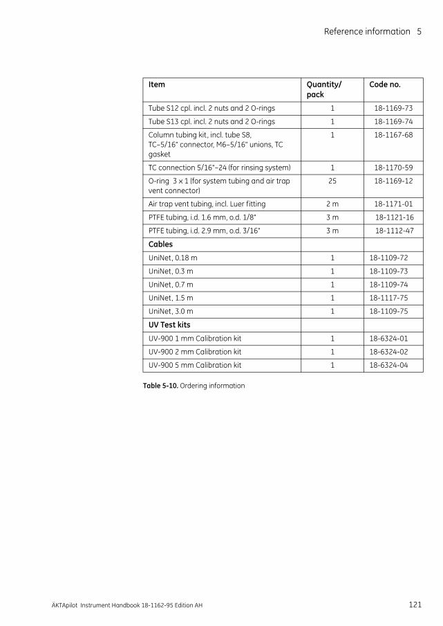
Reference information 5
Table 5-10. Ordering information
Tube S12 cpl. incl. 2 nuts and 2 O-rings 1 18-1169-73
Tube S13 cpl. incl. 2 nuts and 2 O-rings 1 18-1169-74
Column tubing kit , incl. tube S8, TC–5/16" connector, M6–5/16" unions, TC gasket
1 18-1167-68
TC connection 5/16"–24 (for rinsing system) 1 18-1170-59
O-ring 3 x 1 (for system tubing and air trap vent connector)
25 18-1169-12
Air trap vent tubing, incl. Luer fitting 2 m 18-1171-01
PTFE tubing, i.d. 1.6 mm, o.d. 1/8" 3 m 18-1121-16
PTFE tubing, i.d. 2.9 mm, o.d. 3/16" 3 m 18-1112-47
Cables
UniNet, 0.18 m 1 18-1109-72
UniNet, 0.3 m 1 18-1109-73
UniNet, 0.7 m 1 18-1109-74
UniNet, 1.5 m 1 18-1117-75
UniNet, 3.0 m 1 18-1109-75
UV Test kits
UV-900 1 mm Calibration kit 1 18-6324-01
UV-900 2 mm Calibration kit 1 18-6324-02
UV-900 5 mm Calibration kit 1 18-6324-04
Item Quantity/pack
Code no.
ÄKTApilot Instrument Handbook 18-1162-95 Edition AH 121

5 Reference information5.5 Ordering information
122 ÄKTApilot Instrument Handbook 18-1162-95 Edition AH

Index
Index
Numerics2-port union with pressure sensor 2
location ....................................................................................................... 93-port union with pressure sensor 4
location ....................................................................................................... 9
Aabsorbance range ......................................................................................... 110air inlet filter
maintenance ............................................................................................ 38ordering information .............................................................................. 120
air sensorair sensor 1, location .................................................................................. 9air sensor 2, location .................................................................................. 9cleaning .................................................................................................... 46description ....................................................................................... 16, 105ordering information .............................................................................. 119replacing ................................................................................................... 58specifications ......................................................................................... 112
air trapcleaning .................................................................................................... 46description ....................................................................................... 16, 105location ....................................................................................................... 9maintenance ............................................................................................ 38ordering information .............................................................................. 119replacing ................................................................................................... 63valve V4 .................................................................................................... 14valve V4, location ....................................................................................... 9
analog I/O ................................................................................................ 85, 108
Bbaseline drift
conductivity curve .................................................................................... 66
Ccables
ordering information .............................................................................. 121calibrating
ÄKTApilot Instrument Handbook 18-1162-95 Edition AH 123
conductivity cell ....................................................................................... 28pressure sensor 1 ..................................................................................... 23pressure sensor 2 ..................................................................................... 22pressure sensor 3 ..................................................................................... 24pressure sensor 4 ..................................................................................... 22temperature sensor ................................................................................. 27
Index
UV cell ....................................................................................................... 30cell constant ..................................................................................................... 27
calibrating ................................................................................................. 28cGMP demands .................................................................................................. 7check list, before run ........................................................................................ 20check valves
replacing ................................................................................................... 50chemical compatibility ................................................................................... 116chemical resistance guide ............................................................................. 116chromatography techniques ............................................................................. 7cleaning
air sensor .................................................................................................. 46air trap ...................................................................................................... 46check valves ............................................................................................. 40conductivity cell ....................................................................................... 45membrane valves .................................................................................... 42pH electrode ............................................................................................. 44pressure sensor ........................................................................................ 45pumps ....................................................................................................... 40the system ................................................................................................ 39UV cell ....................................................................................................... 43
code numbers ................................................................................................ 118column cleaning ............................................................................................... 40column tubing .................................................................................................. 92Column tubing kit .................................................................................... 92, 121column valves
valve V6 .................................................................................................... 14valve V6, location ....................................................................................... 9valve V7 .................................................................................................... 14valve V7, location ....................................................................................... 9
columns ............................................................................................................ 15check before run ...................................................................................... 20
compensation factorconductivity cell ....................................................................................... 28
componentsdescription ................................................................................................ 95location in the separation unit ........................................................... 9, 83materials ................................................................................................. 115positions in the liquid flow path .............................................................. 88
conductivity cell ............................................................................................... 15calibrating ................................................................................................. 27calibration interval ................................................................................... 21
124 ÄKTApilot Instrument Handbook 18-1162-95 Edition AH
cleaning .................................................................................................... 45description .............................................................................................. 103location ....................................................................................................... 9maintenance ............................................................................................ 37ordering information .............................................................................. 118replacing ................................................................................................... 62specifications .......................................................................................... 111

Index
conductivity curvetroubleshooting ........................................................................................ 66
conductivity range ......................................................................................... 114conductivity temperature compensation ....................................................... 28connectors ........................................................................................................ 16
ordering information .............................................................................. 119controller panel ......................................................................................... 85, 87controls
separation unit ......................................................................................... 82
Ddegree of protection ...................................................................................... 107delay volume .................................................................................................. 107digital I/O ................................................................................................. 85, 107dimensions, separation unit .......................................................................... 107
Eelectrical connections ...................................................................................... 84
Fflow direction valve V5 ..................................................................................... 14
location ....................................................................................................... 9flow path ........................................................................................................... 88flow rate
accuracy ................................................................................................. 109max. allowed during fractionation .......................................................... 16range, system pump and sample pump .............................................. 109reproducibility ........................................................................................ 109specification ........................................................................................... 114system pump ............................................................................................ 13
fraction collector .............................................................................................. 16fuse specification ........................................................................................... 107
Gghost peaks
conductivity curve .................................................................................... 66UV curve ................................................................................................... 65
GLP demands ..................................................................................................... 7gradient composition, specification .............................................................. 109
H
ÄKTApilot Instrument Handbook 18-1162-95 Edition AH 125
hold-up volume .............................................................................................. 107
Iidentification labels .......................................................................................... 10indicator
POWER ...................................................................................................... 19separation unit ......................................................................................... 82

Index
the RUN indicator in UNICORN ................................................................ 20inlet tubing ........................................................................................................ 93inlet valves ........................................................................................................ 14
V1 and V2, location .................................................................................... 9
Llabels
identification ............................................................................................. 10rating ......................................................................................................... 10
liquid feed requirements ................................................................................ 113liquid flow path .......................................................................................... 12, 88liquid flow rates, specification ....................................................................... 114
Mmains cable ...................................................................................................... 84mains power switch ......................................................................................... 19mains voltage ................................................................................................. 107maintenance
daily ........................................................................................................... 36preventive ................................................................................................. 35schedule ................................................................................................... 36
manuals ............................................................................................................ 17measurement range
conductivity cell ....................................................................................... 15pH electrode ............................................................................................. 15UV flow cell ............................................................................................... 15
membrane valvescleaning .................................................................................................... 42description ......................................................................................... 14, 99maintenance ............................................................................................ 38ordering information .............................................................................. 119replacing ................................................................................................... 54specifications .......................................................................................... 112
Method Wizard ................................................................................................. 20mixer ................................................................................................................. 14
description .............................................................................................. 101location ....................................................................................................... 9maintenance ............................................................................................ 38specifications .......................................................................................... 110
mixer chamberordering information .............................................................................. 118replacing ................................................................................................... 53
126 ÄKTApilot Instrument Handbook 18-1162-95 Edition AH
Monitor pH/C-901specifications .......................................................................................... 111
Monitor UV-901description .............................................................................................. 102specifications .......................................................................................... 110
moving the system ........................................................................................... 35

Index
Nnoisy signal
pressure curve ......................................................................................... 68UV curve ................................................................................................... 66
OOn-line filter .................................................................................................... 120operating flow rate ........................................................................................ 114operating instructions ..................................................................................... 19operating pressure ........................................................................................ 114operating principles ......................................................................................... 12optional tubing configuration ......................................................................... 90ordering information ...................................................................................... 118
air inlet filter ........................................................................................... 120air trap .................................................................................................... 119cable ....................................................................................................... 121conductivity cell ..................................................................................... 118membrane valve .................................................................................... 119mixer ....................................................................................................... 118pH electrode ........................................................................................... 118pressure sensors .................................................................................... 119sample pump ......................................................................................... 118system pump .......................................................................................... 118test kit ..................................................................................................... 121tubings .................................................................................................... 120UV cell ..................................................................................................... 118
outlet manifold ................................................................................................. 98outlet tubing ..................................................................................................... 94outlet valves
V8 and V9, location .................................................................................... 9valve V8 .................................................................................................... 14valve V9 .................................................................................................... 14
PpH ...................................................................................................................... 44pH cell holder
description .............................................................................................. 101ordering information .............................................................................. 118replacing ................................................................................................... 62
pH electrode ..................................................................................................... 15calibrating with the electrode fitted in the flow cell .............................. 25calibrating with the electrode outside the flow cell ............................... 26
ÄKTApilot Instrument Handbook 18-1162-95 Edition AH 127
calibration interval ................................................................................... 21check before run ...................................................................................... 20cleaning .................................................................................................... 44description .............................................................................................. 101location ....................................................................................................... 9maintenance ............................................................................................ 36

Index
ordering information .............................................................................. 118replacing ................................................................................................... 61
pH measurement ............................................................................................. 15specifications .......................................................................................... 111
pH range ......................................................................................................... 114piston ......................................................................................................... 96, 97piston rinsing system
tubing configuration ................................................................................ 91power consumption ....................................................................................... 107POWER indicator .............................................................................................. 19preparing the system ....................................................................................... 20pressure sensors .............................................................................................. 13
calibration interval ................................................................................... 21cleaning .................................................................................................... 45description .............................................................................................. 104ordering information .............................................................................. 119replacing ................................................................................................... 56sensor 1, calibrating ................................................................................. 23sensor 1, location ....................................................................................... 9sensor 3, calibrating ................................................................................. 24sensor 3, location ....................................................................................... 9sensor 4, calibrating ................................................................................. 22specifications ................................................................................. 110, 112
priming the system .......................................................................................... 64pump heads
description ................................................................................................ 95outlet ......................................................................................................... 98
Pump P-907 ...................................................................................................... 95description ................................................................................................ 95features ..................................................................................................... 95principle .................................................................................................... 97specifications .......................................................................................... 109
Pump P-908description ................................................................................................ 95features ..................................................................................................... 95specifications .......................................................................................... 109
Rrating labels ...................................................................................................... 10relative humidity ............................................................................................ 107replacing
air sensors ................................................................................................ 58
128 ÄKTApilot Instrument Handbook 18-1162-95 Edition AH
air trap ...................................................................................................... 63check valves ............................................................................................. 50conductivity cell ....................................................................................... 62membrane valve block ............................................................................ 54mixer chamber ......................................................................................... 53pH electrode and cell holder ................................................................... 61

Index
pressure sensors ...................................................................................... 56sample pump ........................................................................................... 47system pump ............................................................................................ 47UV cell ....................................................................................................... 59
replacing spare parts ....................................................................................... 47rinsing system check valve .............................................................................. 96
Ssample pump
description ................................................................................................ 95location ....................................................................................................... 9maintenance ............................................................................................ 36replacing ................................................................................................... 47specifications ......................................................................................... 109
sample valve V3 ............................................................................................... 14location ....................................................................................................... 9
SamplePumpWash .......................................................................................... 64sanitization ....................................................................................................... 40separation unit
components ............................................................................................... 9specifications ......................................................................................... 107
service mode .................................................................................................... 55signal connectors ............................................................................................. 85starting ÄKTApilot system ................................................................................ 19stepper motors ................................................................................................. 14system back-pressure ................................................................................... 114system description ........................................................................................... 81system flow path .............................................................................................. 88system flow rates, specification .................................................................... 114system performance specifications .............................................................. 114system pump
description ................................................................................................ 95location ....................................................................................................... 9maintenance ............................................................................................ 36ordering information .............................................................................. 118replacing ................................................................................................... 47specifications ......................................................................................... 109
SystemPumpWash ........................................................................................... 64
TTC connectors
maintenance ............................................................................................ 38
ÄKTApilot Instrument Handbook 18-1162-95 Edition AH 129
temperature compensation ............................................................................ 28temperature sensor
calibrating ................................................................................................ 27Tool kit ÄKTApilot ............................................................................................ 120troubleshooting
air sensors ................................................................................................ 71

Index
conductivity curve .................................................................................... 66ghost peaks .............................................................................................. 65membrane valves .................................................................................... 70mixer ......................................................................................................... 70pressure sensors ...................................................................................... 71system pump and sample pump ............................................................ 69UV curve ............................................................................................ 65, 66
tubingcheck before run ...................................................................................... 20column ...................................................................................................... 92configuration of the piston rinsing system ............................................. 91description ......................................................................................... 16, 89inlet ........................................................................................................... 93ordering information .............................................................................. 120outlet ......................................................................................................... 94positions in the liquid flow path .............................................................. 88
tubing connectionsmaintenance ............................................................................................ 38specifications .......................................................................................... 113
UUNICORN ............................................................................................................. 8
start and log on ........................................................................................ 19version ...................................................................................................... 81
unionsordering information .............................................................................. 119
UV cellcalibrating ................................................................................................. 30calibration interval ................................................................................... 21cleaning .................................................................................................... 43description .............................................................................................. 102location ....................................................................................................... 9maintenance ............................................................................................ 37measure real length ................................................................................. 30replacing ................................................................................................... 59specifications .......................................................................................... 110
UV curvetroubleshooting ........................................................................................ 65
UV flow cell ....................................................................................................... 15ordering information .............................................................................. 118
UV measurementspecifications .......................................................................................... 110
130 ÄKTApilot Instrument Handbook 18-1162-95 Edition AH
UV wavelength range .................................................................................... 114
Vvalve block
description ................................................................................................ 14viscosity .......................................................................................................... 109
Index
Wwavelength
accuracy ................................................................................................. 110precision ................................................................................................. 110
wetted materials ............................................................................................ 115Wetted parts kit .............................................................................................. 120
ÄKTApilot Instrument Handbook 18-1162-95 Edition AH 131

Index
132 ÄKTApilot Instrument Handbook 18-1162-95 Edition AH


For contact information for your local office,please visitwww.gelifesciences.com/contact
www.gelifesciences.com
GE Healthcare Bio-Sciences ABBjörkgatan 30751 84 UppsalaSweden
GE and GE monogram are trademarks of General Electric Company.
DropDesign, UNICORN, ÄKTA and ÄKTApilot are trademarks of GE Healthcare companies.
Microsoft, Windows and Windows XP are registered trademarks of MicrosoftCorporation.
© 2002-2014 General Electric Company – All rights reserved.First published Dec. 2002
All goods and services are sold subject to the terms and conditions of sale of the company within GE Healthcare which supplies them. A copy of these terms and conditions is available on request. Contact your local GE Healthcare representative for the most current information.
GE Healthcare UK LtdAmersham Place, Little Chalfont, Buckinghamshire, HP7 9NA, UK
GE Healthcare Bio-Sciences Corp800 Centennial Avenue, P.O. Box 1327, Piscataway, NJ 08855-1327, USA
GE Healthcare Europe GmbHMunzinger Strasse 5, D-79111 Freiburg, Germany
GE Healthcare Japan CorporationSanken Bldg. 3-25-1, Hyakunincho, Shinjuku-ku, Tokyo 169-0073, Japan
Instrument Handbook 18-1162-95 AH 02/2014