aeroacoustic analysis of a steam turbine double seat
TRANSCRIPT
Aeroacoustic analysis of a steam turbine double seat control valve
C. Bianchini, R. Da Soghe
Ergon Research s.r.l.via Panciatichi 92, 50127 Florence, Italy
E. Imparato, L. Cosi
GE Oil & Gasvia Matteucci 2, 50127 Florence, Italy
ABSTRACTA computational analysis of the acoustic response of a double seat valve employed in the controlstage of an industrial steam turbine was performed to verify possible criticalities in terms ofmechanical stresses. Unsteady CFD was exploited to evaluate the unsteady pressure loads onselected positions. Turbulent flow simulations adopt the Scale Adaptive Simulation principle, asimplemented in Ansys CFX 14.5 code, to partially resolve turbulence spectrum. 180 deg sym-metric computational models were used, after verification that principal flow features of the fullgeometry were adequately reproduced, to maintain grid size below 20M cells. Purely acousticcomputations exploiting the homogeneous Helmoltz equation were conducted first to identifynatural acoustic modes and secondly to verify the forced response subjected to the unsteadypressure loads computed by CFD. Investigated frequency range is extended from 5 to 1000 Hzto comprehend all relevant structural modes. 4 different flow conditions were investigated torepresent the entire operating range both in terms of characteristic Reynolds and Mach num-ber. Obtained results shows that principal forcing frequency is characterized by a constantStrouhal number based on plug diameter and bulk flow velocity while main load amplitude isproportional to Reynolds number. Acoustic modes correspond to much higher frequencies sothat the forced response does not generate critical stress levels on both valve stem and chest.
1
Proceedings of
11th European Conference on Turbomachinery Fluid dynamics & Thermodynamics
ETC11, March 23-27, 2015, Madrid, Spain
OPEN ACCESS
Downloaded from www.euroturbo.eu Copyright © by the Authors
NOMENCLATURED Valve diameter [m]dt Computational time step [s]dp Mean static pressure loss (inlet-outlet) [Pa]f Characteristic frequency [s−1]H Valve lift [m]k Turbulent kinetic energy [m2/s2]l Characteristic length [m]L Discharge duct length [m]LRANS Characteristic turbulent length for RANS models [m]L∆ Characteristic turbulent length based on grid scale [m]m Mass flow rate [kg/s]mc Critical mass flow rate [kg/s]Ma Mach number [−]p Static pressure [Pa]Rij Velocity correlations u′
iu′j [m
2/s2]Re Reynolds number [−]St Strouhal number [−]U Velocity [m/s]u′, v′, w′ x,y,z, directed velocity fluctuations [m/s]ω Turbulent specific dissipation rate [s−1]
INTRODUCTIONDesign of large and medium scale steam turbine currently needs to address an increasing demand
for operational flexibility. This is due to the frequent partialization caused both by the fluctuatingavailability of renewable power sources, which are ceaselessly enlarging their contribution to the totalpower generation, and to their use for decentralized purposes or mechanical drive applications whichrequire rapid adjustment to consumption power loads.
These requirements affect the design of most components as many will face off-design conditionsfor a large part of their lifetime but above all become crucial for the main control valve which regulatethe overall pressure ratio available for the steam expansion thus determining the operating conditionsof the entire machine.
Clari et al. (2011) and Tecza et al. (2010) propose an innovative control valve design, with respectto standard common lift bar mounting which is prone to oscillating flows possibly leading to plugor stem failures, to reduce or prevent fluid structure interaction causing self-excited vibration in theoriginal design, which protects the control mechanism from the steam flow in the steam chest andthrough the valve.
Liu et al. (2008) studied the pressure drops across these valves by means of experimental investi-gation and numerical simulation. Based on the analysis of thermodynamic process in control valve,they deduced a relationship of flow coefficient, area ratio of valve outlet section to seat diametersection, pressure ratio and total pressure loss coefficient with a relative deviations between formularesults and experimental results within 3%. They also stated that systematic measurement results in-dicate that control valve operates steadily when the Mach numbers at valve inlet and outlet sectionsare less than 0.15 viceversa stem vibration is registered when the pressure ratio is from 0.8 to 0.4.
Also Morita et al. (2004) investigated the problem of stem vibration including both computationaland experimental analysis. They performed Large Eddy Simulation of the air flow within a pipe
2
duct throttled with an emi-sphere plug head which showed to compare well with unsteady pressuremeasurements on the valve and the valve seats. The analysis was later expanded to include realsteam flows finding out that the two gas show the same rotating pressure fluctuations: amplitude ofsuch fluctuations increases with the lift while the propagation frequency decreases Morita and Inada(2007).
More recently Zanazzi et al. (2013) performed a numerical investigation of the unsteady behaviourof steam turbine partition valve in throttling conditions. This work is interesting because they com-pared a simplified in-house procedure with full 3D CFD analysis and experiments available for asingle seat valve with axisymmetric stem under a large number of working conditions which arecharacterized by 5 different unsteady modes. They were able to reproduce accurately the forcingfrequencies despite the fact that pressure amplitudes were strongly underestimated by the CFD pro-cedure.
The aim of present work is to investigate the unsteady forcing acting on the stem and the chestof a double seat valve employed in the regulation of medium sized (up to 80 MW) steam turbine formechanical drive applications (e.g. oil refinery). In particular it is of interest to verify if the main fluiddynamic modes excite the acoustic natural frequencies to prevent possible resonance phenomena.3D computations were used to resolve the mean and fluctuating turbulent flow field. Being directresolution of the turbulent field infeasible with available computational resources for the configurationof interest, an hybrid method based on the Scale Adaptive Simulation technique was exploited tosimulate the large scale turbulent structures determining the unsteady aerodynamic loads.
Several operating conditions were analyzed ranging from almost closed shutter with choked flowto fully open valve at maximum flow rate. The unsteady behaviour of the flow is described moni-toring pressure signals at various locations and analysing their spectral distribution. Such pressurefluctuations were finally exploited as constraints to compute the forced acoustic internal field.
Similar analysis, showing the high interest of scientific community in the characterization of theunsteady valve behaviour, have been recently presented by Musch et al. (2014) and Domnick et al.(2014) employing equivalent numerical techniques.
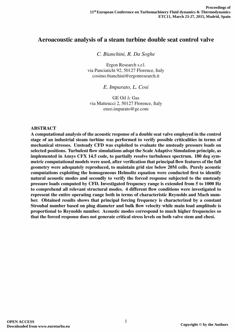
INVESTIGATED CASESThis paper is focused on the double seat valve depicted in Figure 1. This valve is composed by a
radial admission duct which feeds the axial turbine through two annular orifices regulated by meansof the same two-plug stem. The lower seat directly admits the steam to the main discharge duct whilethe upper one is collected by a spiral which surrounds the internal steam chest.
This valve is investigated with the stem opened at three different heights above the seat (H/D =0.040, 0.153, 0.404), representing two start-up configurations and full load positioning. In terms of
Table 1: Investigated cases
Inlet Mach Inlet Reynolds H/D10−2 106
Case 1 1.948 10.96 0.040Case 2 7.353 41.24 0.153Case 3 9.105 53.64 0.404Case 4 13.206 64.55 0.404Case 5 9.376 24.27 0.404Case 6 14.064 85.67 0.404
3
Figure 1: Overview of double seat valve geometry.
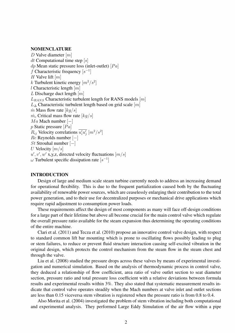
flow conditions the two closed plug cases were investigated with a large pressure drop generatingfully choked throats as encountered in standard start-up procedure. The wide open valve configu-ration instead is employed under a variety of conditions among which 4 different simulations wereperformed to well represent the entire range of interest. A summary of investigated flow conditions isreported in Table 1 as a function of inlet Mach and Reynolds number and stem positioning.
An overview of the effective flow conditions which the valve may be subjected is summarized inFigure 2 in terms of inflow Mach and Reynolds numbers where dots indicate the cases investigated inthis analysis reported in Table 1.
Figure 2: Possible operating conditions.
NUMERICAL METHODSAs better reported in Bianchini et al. (2014), this analysis, based on the procedure proposed and
validated by Zanazzi et al. (2013), exploits the k − ω SST SAS model in the version implementedwithin the commercial CFD code Ansys R⃝ CFX v14.5.
In terms of modelling it is worth recalling that steam is treated as a homogeneous rarefied gas
4
following ideal gas law. Despite being substantially isothermal, total energy equation was solved withadiabatic conditions on all the walls to consider thermal gradients generated due to the accelerationwithin the valve throat which in the choked cases is quite relevant.
A physical time step dt = 1e−4 was chosen based on physics and computational efficiency con-siderations. Convergence was guaranteed for each time step by RMS residuals for continuity andmomentum below 10−5. To obtain converged statistics and maximise the investigated spectra, totalsimulation time was extended over 0.4 s for a total of more than 4000 time steps. Transient effectsdue to initialization were purged activating time averaging and signal monitoring after 0.2 s. As it isdesired for direct resolution of turbulent flows, highest available order of discretization (2nd order astypical for unstructured codes) for both convective and time advancement terms are used exploitingthe high resolution formulation to improve solver robustness.
The computational domain employed in this analysis extends in the upstream direction up to thesteam chest inflow section while downstream the discharge duct is extruded for L > 10D to avoidbackflow or any interaction with the boundary condition.
Even though in principle for turbulent flows the use of symmetry conditions should always beavoided as the flow is symmetric only in a time averaged sense while the instantaneous flux acrossthe plane of symmetry is not zero, it would be convenient to force the symmetric behavior by meansof boundary conditions to reduce the computational cost. In order to verify the applicability of thisassumption, the full 360◦ geometry was simulated for Case 1 showing that the flow field within thevalve exhibits an almost symmetrical behavior not only in terms of time averaged flow field but alsoin terms of turbulent fluctuations as demonstrated in Bianchini et al. (2014).
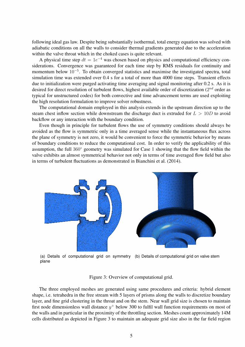
(a) Details of computational grid on symmetryplane
(b) Details of computational grid on valve stem
Figure 3: Overview of computational grid.
The three employed meshes are generated using same procedures and criteria: hybrid elementshape, i.e. tetrahedra in the free stream with 5 layers of prisms along the walls to discretize boundarylayer, and fine grid clustering in the throat and on the stem. Near wall grid size is chosen to maintainfirst node dimensionless wall distance y+ below 300 to fulfil wall function requirements on most ofthe walls and in particular in the proximity of the throttling section. Meshes count approximately 14Mcells distributed as depicted in Figure 3 to maintain an adequate grid size also in the far field region
5

Figure 4: Pressure probe positioning.
to permit a sufficient resolution of the turbulent flow field. Employed grids guarantee high qualityelements as the averaged orthogonality angle is above 70◦ and the mesh expansion factor below 3.
Data analysisThe synthesis of 3D computations of turbulent flows in values useful to characterize the unsteady
behavior of the fluid is not always straightforward due to both the large number of data produced andthe chaotic nature of turbulence which makes the analysis of principal flow structures a challengingtask. In this case for example, the work is dedicated to an estimate of the fluctuating aerodynamicforcing acting on the stem and the steam chest to verify possible interaction with the structure eigen-modes. The idea of collecting instantaneous pressure fields on all computational nodes of the surfacesof interest for the entire simulated time is not practical. Apart from problems arising due to the size ofthe dataset, time signals contains contributions pulsating at different frequencies which are difficult,virtually impossible, to analyze in the time domain.
In order to completely characterize the main forces acting on the valve in a light and simple way,pressure signal is registered in a reduced set of nodes together with global forces and moments actingon the stem. Most interesting locations were identified on overhung structures such as the stem plugand the chest narrowing. As depicted in Figure 4, 8 different positions were selected to be repre-sentative of pressure loads on the shutter and on the external structure; for each position 9 probeswere distributed tangentially with a spacing of 22.5◦ for a total of 72 pressure signals registered. Tomore easily identify the monitor points they are named with a composite word identifying nearestseat (Up/Down), closest surface (Stem/Chest), relative position respect to the valve throat (In/Out)and finally the angular coordinate (e.g Up Stem Out 45). Discrete Fourier Transform was hence ap-plied to every local signal permitting to highlight principal frequencies, relative phase of fluctuations,interactions between different zones of the domain.
With the above mentioned numerical set-up, frequencies ranging between 5 and 5000 Hz areanalyzed providing a sufficient resolution to properly characterize the range of interest (10-1000 Hz).
6
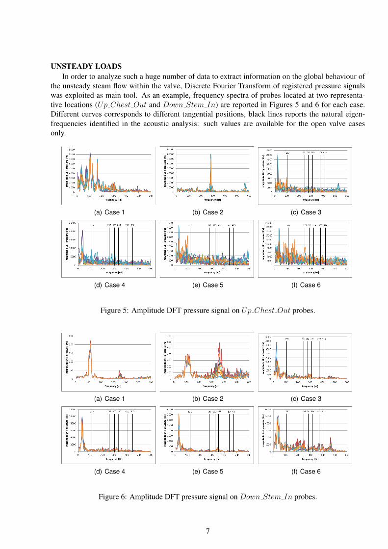
UNSTEADY LOADSIn order to analyze such a huge number of data to extract information on the global behaviour of
the unsteady steam flow within the valve, Discrete Fourier Transform of registered pressure signalswas exploited as main tool. As an example, frequency spectra of probes located at two representa-tive locations (Up Chest Out and Down Stem In) are reported in Figures 5 and 6 for each case.Different curves corresponds to different tangential positions, black lines reports the natural eigen-frequencies identified in the acoustic analysis: such values are available for the open valve casesonly.
(a) Case 1 (b) Case 2 (c) Case 3
(d) Case 4 (e) Case 5 (f) Case 6
Figure 5: Amplitude DFT pressure signal on Up Chest Out probes.
(a) Case 1 (b) Case 2 (c) Case 3
(d) Case 4 (e) Case 5 (f) Case 6
Figure 6: Amplitude DFT pressure signal on Down Stem In probes.
7
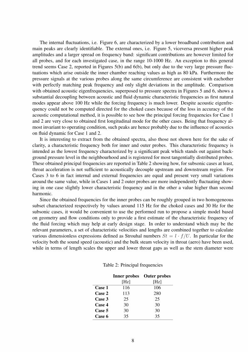
The internal fluctuations, i.e. Figure 6, are characterized by a lower broadband contribution andmain peaks are clearly identifiable. The external ones, i.e. Figure 5, viceversa present higher peakamplitudes and a larger spread on frequency band: significant contributions are however limited forall probes, and for each investigated case, in the range 10-1000 Hz. An exception to this generaltrend seems Case 2, reported in Figures 5(b) and 6(b), but only due to the very large pressure fluc-tuations which arise outside the inner chamber reaching values as high as 80 kPa. Furthermore thepressure signals at the various probes along the same circumference are consistent with eachotherwith perfectly matching peak frequency and only slight deviations in the amplitude. Comparisonwith obtained acoustic eigenfrequencies, superposed to pressure spectra in Figures 5 and 6, shows asubstantial decoupling between acoustic and fluid dynamic characteristic frequencies as first naturalmodes appear above 100 Hz while the forcing frequency is much lower. Despite acoustic eigenfre-quency could not be computed directed for the choked cases because of the loss in accuracy of theacoustic computational method, it is possible to see how the principal forcing frequencies for Case 1and 2 are very close to obtained first longitudinal mode for the other cases. Being that frequency al-most invariant to operating condition, such peaks are hence probably due to the influence of acousticson fluid dynamic for Case 1 and 2.
It is interesting to extract from the obtained spectra, also those not shown here for the sake ofclarity, a characteristic frequency both for inner and outer probes. This characteristic frequency isintended as the lowest frequency characterized by a significant peak which stands out against back-ground pressure level in the neighbourhood and is registered for most tangentially distributed probes.These obtained principal frequencies are reported in Table 2 showing how, for subsonic cases at least,throat acceleration is not sufficient to acoustically decouple upstream and downstream region. ForCases 3 to 6 in fact internal and external frequencies are equal and present very small variationsaround the same value, while in Cases 1 and 2 outer probes are more independently fluctuating show-ing in one case slightly lower characteristic frequency and in the other a value higher than secondharmonic.
Since the obtained frequencies for the inner probes can be roughly grouped in two homogeneoussubset characterized respectively by values around 115 Hz for the choked cases and 30 Hz for thesubsonic cases, it would be convenient to use the performed run to propose a simple model basedon geometry and flow conditions only to provide a first estimate of the characteristic frequency ofthe fluid forcing which may help at early design stage. In order to understand which may be therelevant parameters, a set of characteristic velocities and lengths are combined together to calculatevarious dimensionless expressions defined as Strouhal numbers St = l · f/U . In particular for thevelocity both the sound speed (acoustic) and the bulk steam velocity in throat (aero) have been used,while in terms of length scales the upper and lower throat gaps as well as the stem diameter were
Table 2: Principal frequencies
Inner probes Outer probes[Hz] [Hz]
Case 1 116 106Case 2 113 280Case 3 25 25Case 4 30 30Case 5 30 30Case 6 35 35
8

Figure 7: Strouhal number evaluation for inner probes.
employed. In such a way 6 different Strouhal may be computed as plotted in Figure 7 in a log-loggraph for the inner probes. It is worth noting how the only Strouhal showing results of the sameorder of magnitude for every tested conditions is that defined on the aerodynamic velocity in thethroat and the stem diameter. With a constant St=0.15, obtained averaging the 6 investigated cases,it is possible to evaluate characteristic internal frequencies with an average error of 10% which isgenerally compatible with safety coefficients employed by structural designers to avoid dangerousinteractions with structure eigenfrequencies.
Also in terms of peak amplitudes, the two groups of subsonic and choked cases behave differently.For the supersonic cases in fact, the inner chamber is almost steady while the amplitude of fluctuationsdue to the annular jet is large reaching values higher than 40 kPa as a tangential average, resultingnearly 4 times higher than in the most critical subsonic case. The subsonic cases viceversa show asexpected a stronger link between internal and external oscillation magnitude: outer fluctuations arelimited to nearly the double of their respective upstream homologous. In order to provide a descriptionof how these pressure fluctuations depends on the operating conditions and on the probe position,maximum Fourier coefficient was averaged tangentially for each position and plotted in Figure 8
Figure 8: Fluctuation amplitudes for subsonic cases.
9
against Reynolds number for the subsonic cases. Lower seat is subjected to higher unsteady loadsthan the upper one, in particular those directed on the stem of the valve which shows an increasingtrend with Reynolds number. This fluctuation is propagated towards the other probe positions withattenuation proportional to fluid reference density which regulates flow inertia. As a consequenceCase 3 and 6, which correspond to Re = 5.36 · 107 and 8.57 · 107 respectively, results in lowerminimal oscillation. It is interesting to note that the upper seat, due to its shaping, excites the chestmuch more than the stem.
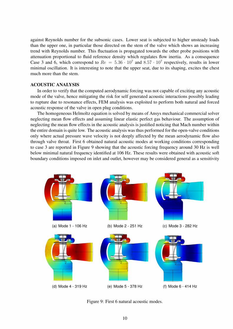
ACOUSTIC ANALYSISIn order to verify that the computed aerodynamic forcing was not capable of exciting any acoustic
mode of the valve, hence mitigating the risk for self generated acoustic interactions possibly leadingto rupture due to resonance effects, FEM analysis was exploited to perform both natural and forcedacoustic response of the valve in open plug conditions.
The homogeneous Helmoltz equation is solved by means of Ansys mechanical commercial solverneglecting mean flow effects and assuming linear elastic perfect gas behaviour. The assumption ofneglecting the mean flow effects in the acoustic analysis is justified noticing that Mach number withinthe entire domain is quite low. The acoustic analysis was thus performed for the open-valve conditionsonly where actual pressure wave velocity is not deeply affected by the mean aerodynamic flow alsothrough valve throat. First 6 obtained natural acoustic modes at working conditions correspondingto case 3 are reported in Figure 9 showing that the acoustic forcing frequency around 30 Hz is wellbelow minimal natural frequency identified at 106 Hz. These results were obtained with acoustic softboundary conditions imposed on inlet and outlet, however may be considered general as a sensitivity
(a) Mode 1 - 106 Hz (b) Mode 2 - 251 Hz (c) Mode 3 - 282 Hz
(d) Mode 4 - 319 Hz (e) Mode 5 - 378 Hz (f) Mode 6 - 414 Hz
Figure 9: First 6 natural acoustic modes.
10
analysis showed low changes in case of hard sound boundary. All solid walls are modelled as soundhard boundary.
Fourier transformed pressure history at monitored probes were then used to perform a forcedacoustic analysis. DOF constraints were imposed on the closest nodes of the FEM mesh to respectreal and imaginary components of pressure DFT. Based on the previous natural modes, locationsprone to high amplitude fluctuations were selected (max and mean peak value for each mode) andmonitored in the entire range of investigated frequencies.
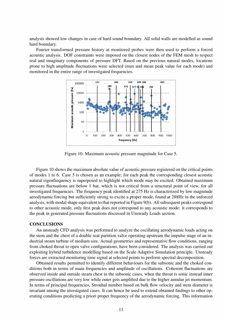
Figure 10: Maximum acoustic pressure magnitude for Case 5.
Figure 10 shows the maximum absolute value of acoustic pressure registered on the critical pointsof modes 1 to 6. Case 5 is chosen as an example; for each peak the corresponding closest acousticnatural eigenfrequency is superposed to highlight which mode may be excited. Obtained maximumpressure fluctuations are below 1 bar, which is not critical from a structural point of view, for allinvestigated frequencies. The frequency peak identified at 275 Hz is characterized by low magnitudeaerodynamic forcing but sufficiently strong to excite a proper mode, found at 288Hz in the unforcedanalysis, with modal shape equivalent to that reported in Figure 9(b). All subsequent peaks correspondto other acoustic mode, only first peak does not correspond to any acoustic mode: it corresponds tothe peak in generated pressure fluctuations discussed in Unsteady Loads section.
CONCLUSIONSAn unsteady CFD analysis was performed to analyze the oscillating aerodynamic loads acting on
the stem and the chest of a double seat partition valve operating upstream the impulse stage of an in-dustrial steam turbine of medium size. Actual geometries and representative flow conditions, rangingfrom choked throat to open valve configurations, have been considered. The analysis was carried outexploiting hybrid turbulence modelling based on the Scale Adaptive Simulation principle. Unsteadyforces are extracted monitoring time signal at selected points to perform spectral decomposition.
Obtained results permitted to identify different behaviours for the subsonic and the choked con-ditions both in terms of main frequencies and amplitude of oscillations. Coherent fluctuations areobserved inside and outside steam chest in the subsonic cases, when the throat is sonic instead innerpressure oscillations are very low while outer gets amplified due to the higher annular jet momentum.In terms of principal frequencies, Strouhal number based on bulk flow velocity and stem diameter isinvariant among the investigated cases. It can hence be used to extend obtained findings to other op-erating conditions predicting a priori proper frequency of the aerodynamic forcing. This information
11
is useful to guarantee from the early design stage the decoupling between aerodynamic, acoustic andstructural eigenfrequency.
Finally acoustic analysis was exploited to verify that maximum sound pressure within the valvewere maintained below acceptable levels from a mechanical point of view when subjected to thepredicted fluctuating loads.
REFERENCESC. Bianchini, R. Da Soghe, E. Imparato, and L. Cosi. Numerical analysis of the unsteady loads on a
steam turbine double seat control valve. ASME Conference Proceedings, 2014(26982), 2014.
Manuel B. Clari, Thomas Polklas, and Franz Joos. Three-dimensional flow separations in the diffuserof a steam turbine control valve. ASME Conference Proceedings, 2011(54679):2327–2334, 2011.
C. B. Domnick, F. K. Benra, H. J. Dohmen, and C. Musch. Numerical investigation on the time-variant flow field and dynamic forces acting in steam turbine inlet valves. ASME Conference Pro-ceedings, 2014(25632), 2014.
Guanwei Liu, Shunsen Wang, Hui Guo, Jingru Mao, Zhenping Feng, and Xiaowei Xiang. Investiga-tion on flow characteristics and stability of control valves for steam turbines. ASME ConferenceProceedings, 2008(43154):811–820, 2008.
Ryo Morita and Fumio Inada. Pressure fluctuations around steam control valve: Steam experimentsand CFD calculations. ASME Conference Proceedings, 2007(26444):421–427, 2007. doi: 10.1115/PVP2007-26444. URL http://link.aip.org/link/abstract/ASMECP/v2007/i42827/p421/s1.
Ryo Morita, Fumio Inada, Michitsugu Mori, Kenichi Tezuka, and Yoshinobu Tsujimoto. CFD calcu-lation and experiments of unsteady flow on control valve. ASME Heat Transfer Fluids EngineeringSummer Conference, 2004(HT-FED04-56017), 2004.
C. Musch, F. Deister, G. Zimmer, I. Balkowski, P. Bruggemann, and W. Haslinger. A new emergency-stop and control-valve design part 2: Validation of numerical model and shape optimization. ASMEConference Proceedings, 2014(25117), 2014.
Joseph Tecza, Gocha Chochua, and Randy Moll. Analysis of fluid-structure interaction in a steamturbine throttle valve. ASME Conference Proceedings, 2010(44021):2329–2338, 2010.
Giorgio Zanazzi, Ottmar Schaefer, Colin Ridoutt, and Michael Sell. Unsteady CFD simulation ofcontrol valve in throttling conditions and comparison with experiments. ASME Conference Pro-ceedings, 2013(94788), 2013.
12