afrl-rq-wp-tr-2013-0078 - defense technical information center · afrl-rq-wp-tr-2013-0078 . ... 5.4...
TRANSCRIPT

AFRL-RQ-WP-TR-2013-0078
CENTER FOR MICRO AIR VEHICLE STUDIES P.G. Huang Wright State University FEBRUARY 2013 Final Report
Approved for public release; distribution unlimited. See additional restrictions described on inside pages
STINFO COPY
AIR FORCE RESEARCH LABORATORY AEROSPACE SYSTEMS DIRECTORATE
WRIGHT-PATTERSON AIR FORCE BASE, OH 45433-7542 AIR FORCE MATERIEL COMMAND
UNITED STATES AIR FORCE

NOTICE AND SIGNATURE PAGE
Using Government drawings, specifications, or other data included in this document for any purpose other than Government procurement does not in any way obligate the U.S. Government. The fact that the Government formulated or supplied the drawings, specifications, or other data does not license the holder or any other person or corporation; or convey any rights or permission to manufacture, use, or sell any patented invention that may relate to them. This report was cleared for public release by the USAF 88th Air Base Wing (88 ABW) Public Affairs Office (PAO) and is available to the general public, including foreign nationals. Copies may be obtained from the Defense Technical Information Center (DTIC) (http://www.dtic.mil). AFRL-RQ-WP-TR-2013-0078 HAS BEEN REVIEWED AND IS APPROVED FOR PUBLICATION IN ACCORDANCE WITH ASSIGNED DISTRIBUTION STATEMENT. *//Signature// //Signature// PHILIP S. BERAN THOMAS CO Project Manager Design and Analysis Branch Control Automation Branch Aerospace Vehicles Division Aerospace Vehicles Division //Signature// FRANK WITZMAN, Chief Aerospace Vehicles Division Aerospace Systems Directorate This report is published in the interest of scientific and technical information exchange, and its publication does not constitute the Government’s approval or disapproval of its ideas or findings. *Disseminated copies will show “//Signature//” stamped or typed above the signature blocks.

REPORT DOCUMENTATION PAGE Form Approved OMB No. 0704-0188
The public reporting burden for this collection of information is estimated to average 1 hour per response, including the time for reviewing instructions, searching existing data sources, gathering and maintaining the data needed, and completing and reviewing the collection of information. Send comments regarding this burden estimate or any other aspect of this collection of information, including suggestions for reducing this burden, to Department of Defense, Washington Headquarters Services, Directorate for Information Operations and Reports (0704-0188), 1215 Jefferson Davis Highway, Suite 1204, Arlington, VA 22202-4302. Respondents should be aware that notwithstanding any other provision of law, no person shall be subject to any penalty for failing to comply with a collection of information if it does not display a currently valid OMB control number. PLEASE DO NOT RETURN YOUR FORM TO THE ABOVE ADDRESS.
1. REPORT DATE (DD-MM-YY) 2. REPORT TYPE 3. DATES COVERED (From - To) February 2013 Final 30 June 2010 – 31 January 2013
4. TITLE AND SUBTITLE
CENTER FOR MICRO AIR VEHICLE STUDIES 5a. CONTRACT NUMBER
FA8650-10-2-3039 5b. GRANT NUMBER
5c. PROGRAM ELEMENT NUMBER 62201F
6. AUTHOR(S)
P.G. Huang 5d. PROJECT NUMBER
2401 5e. TASK NUMBER 5f. WORK UNIT NUMBER
Q060 7. PERFORMING ORGANIZATION NAME(S) AND ADDRESS(ES): 8. PERFORMING ORGANIZATION
Wright State University 3640 Colonel Glenn Highway Dayton, OH 45435-0001
REPORT NUMBER
9. SPONSORING/MONITORING AGENCY NAME(S) AND ADDRESS(ES) 10. SPONSORING/MONITORING Air Force Research Laboratory Aerospace Systems Directorate Wright-Patterson Air Force Base, OH 45433-7542 Air Force Materiel Command United States Air Force
AGENCY ACRONYM(S) AFRL/RQVC
11. SPONSORING/MONITORING AGENCY REPORT NUMBER(S) AFRL-RQ-WP-TR-2013-0078
12. DISTRIBUTION/AVAILABILITY STATEMENT Approved for public release; distribution unlimited.
13. SUPPLEMENTARY NOTES PA Case Number: 88ABW-2013-1337; Clearance Date: 20 Mar 2013. Report contains color.
14. ABSTRACT This report summarizes the activities conducted at the Center for Micro Air Vehicle Studies (CMAVS) from 2010 to 2013. The Center was formed to serve the needs of the Air Force in fundamental research and development of micro airplanes for indoor and urban areas. CMAVS organizational focuses include: 1. rapid manufacturing for hands-on development of flight worthy Micro Air Vehicles (MAVs); 2. assisting research groups at AFRL in manufacturing different MAV parts; 3. testing new innovation and ideas for further MAV development, and 4. training students in advanced manufacturing techniques.
15. SUBJECT TERMS micro air vehicle, unsteady aerodynamics, mechanisms, structural layout
16. SECURITY CLASSIFICATION OF: 17. LIMITATION OF ABSTRACT:
SAR
18. NUMBER OF PAGES
50
19a. NAME OF RESPONSIBLE PERSON (Monitor) a. REPORT Unclassified
b. ABSTRACT Unclassified
c. THIS PAGE Unclassified
Philip S. Beran 19b. TELEPHONE NUMBER (Include Area Code)
N/A
Standard Form 298 (Rev. 8-98) Prescribed by ANSI Std. Z39-18

i Approved for public release; distribution unlimited.
TABLE OF CONTENTS Content Page
LIST OF FIGURES ...............................................................................................................................ii
LIST OF TABLES ................................................................................................................................ iv
1.0 SUMMARY ............................................................................................................................ 1
2.0 ACADEMIC ACTIVITIES ......................................................................................................... 2
2.1 Students ................................................................................................................................. 2
2.2 Open House Events ............................................................................................................... 3
2.3 Publications ........................................................................................................................... 4
3.0 Collaboration with AFRL ...................................................................................................... 5
3.1 Designing and Building Parts and Components for AFRL ...................................................... 5
3.2 Building Wing Manufacturing Capability ............................................................................ 13
3.3 NATO AVT-184: WSU-Delft Collaboration ........................................................................... 15
4.0 Flight Lab Testing ............................................................................................................... 19
4.1 MAV Configurations Developed .......................................................................................... 19
4.2 Summary Description of Aircraft Flight Tests ..................................................................... 20
4.3 Vehicle Motion Capture ...................................................................................................... 23
4.4 Qualitative Findings ............................................................................................................. 23
5.0 Technical Achievement ...................................................................................................... 24
5.1 Wing Designs and Optimization .......................................................................................... 24
5.2 Miniaturization of MAV Designs ......................................................................................... 29
5.3 FSI Simulation of MAV ......................................................................................................... 31
5.4 Development of a Continuously Variable Transmission (CVT) ........................................... 33
6.0 Transition to the Future ..................................................................................................... 37
7.0 Conclusions ........................................................................................................................ 39
List of Symbols, Abbreviations, and Acronyms ............................................................................. 40

ii Approved for public release; distribution unlimited.
LIST OF FIGURES Figure Page
Figure 1: WSU's CMAVS Team Achievement ................................................................................. 2
Figure 2: Topological Optimization Designs: Case 1 (Left) and Case 3 (Right) .............................. 5
Figure 3: Insect Thorax Mechanism ............................................................................................... 5
Figure 4: Thorax Computational Modeling: Mesh (Left) and Stress Distribution (Right) .............. 6
Figure 5: Thorax Static Testing ........................................................................................................ 7
Figure 6: Angular Deflection of Compliant Mechanism Designs .................................................... 7
Figure 7: Dynamic Model: Entire Apparatus (Left) and Mechanism Close-Up (Right) .................. 8
Figure 8: AFRL Split-Cycle Frame.................................................................................................... 8
Figure 9: AFRL Split-Cycle Frame with Motors and Wings ............................................................. 9
Figure 10: AFRL Design Schematic for Frame Operation ............................................................... 9
Figure 11: First Attempt at Combining Split-Cycle Kinematics with Large-Angle Flapping .......... 10
Figure 12: Schematic of Combined Gearing ................................................................................. 11
Figure 13: 3D Plot of Angles of Each Component during Operation ............................................ 11
Figure 14: Most Recent Redesign of Combined WSU and AFRL Efforts ...................................... 12
Figure 15: Components and Parts Produced At CMAVS .............................................................. 13
Figure 16: 3D Print of a Wing Design ........................................................................................... 14
Figure 17: Silicon Mold to Lay Carbon Fiber Tow ........................................................................ 14
Figure 18: Wing Design for Goff Mechanism ................................................................................ 15
Figure 19: Two Different Wing Configurations (Left: Wing I, Right: Wing II) .............................. 16
Figure 20: Three Different Cross-Strut Patterns .......................................................................... 16
Figure 21: Open Test Section Wind Tunnel ................................................................................. 17
Figure 22: Center Gear with Magnets........................................................................................... 17
Figure 23: Magnet Sensor ............................................................................................................ 18
Figure 24: Stereo PIV System ....................................................................................................... 18
Figure 25: Standard Model with Reflective Tape ........................................................................ 19
Figure 26: “Big Bird” Model with Reflective Tape ....................................................................... 20
Figure 27: Quadrotor with Four Pearl Markers ............................................................................ 20
Figure 28: Typical Flight Paths for Testing of Max Climb ............................................................. 22
Figure 29: Comstock-Needham Based Morphology .................................................................... 25
Figure 30: Insect Wing Comparison: (Top) Bumblebee; (Center) Cicada; (Bottom) Wasp ......... 26
Figure 31: Flapping of Artificial Wings .......................................................................................... 26
Figure 32: Structure of a Wing ..................................................................................................... 27
Figure 33: Optimization of Wing Designs .................................................................................... 28

iii Approved for public release; distribution unlimited.
Figure List of Figures (Continued) Page
Figure 34: Experimental Comparison of Different Wing Designs ................................................. 28
Figure 35: Micro Gearing and Assembling .................................................................................... 29
Figure 36: Mini MAV (4 g) ............................................................................................................ 29
Figure 37: Manufacturing of 3D Gear System .............................................................................. 30
Figure 38: Miniaturization of Gears ............................................................................................. 31
Figure 39: Abaqus Representation of Bio-Inspired Wing ............................................................ 32
Figure 40: Pressure Contours in SC/Tetra from FSI Analysis ....................................................... 33
Figure 41: Large CVT Prototype .................................................................................................... 34
Figure 42: Comparison of the Large and Small CVT Prototypes .................................................. 34
Figure 43: CVT Prototype with Flapping Mechanism .................................................................. 35
Figure 44: Testing CVT Prototype Model ..................................................................................... 36
Figure 45: Complex Shape Designs Using Additive Manufacturing .............................................. 37
Figure 46: The Lattice Sub-Microstructure .................................................................................. 38

iv Approved for public release; distribution unlimited.
LIST OF TABLES Table Page
Table 1: Summary of Aircraft Flight Tests (2013) ......................................................................... 21
Table 2: Comparison of Different MAV Configurations for Four Test Scenarios ......................... 23

1 Approved for public release; distribution unlimited.
1.0 SUMMARY This report summarizes the activities conducted at the Center for Micro Air Vehicle Studies (CMAVS) from 2010 to 2013. The Center was formed to serve the needs of the Air Force Research Laboratory (AFRL) in research of development of micro airplanes. CMAVS was a collaborative activity between AFRL and Wright State University structured through a cooperative research agreement. Our organizational focuses include:
1. Rapid manufacturing for hands-on development of flight worthy Micro Air Vehicles (MAV),
2. Assisting research groups at AFRL in manufacturing different MAV parts, 3. Testing new innovation and ideas for further MAV development, and 4. Training students in advanced manufacturing techniques.
In section 2, the student academic activities are discussed, including student successes based on the project learning experiences, two open house events we had, and a list of student publications. The collaborative activities associated with AFRL and other international partners are highlighted in section 3. The activities include the design and manufacturing services we offered to different AFRL MAV teams, the development of CMAVS wing manufacturing capability, and the collaboration with Delft University of Technology (TU Delft) in support of the NATO AVT-184 Task Group. Three versions of MAVs were tested in the indoor flight lab of AFRL. A discussion of the flight testing is given in section 4. The technical achievements of CMAVS are provided in section 5. Four major activities were conducted during this period, including wing designs and optimization, miniaturization of MAV designs, fluid-structure interaction (FSI) simulation of MAVs, and development of a continuously variable transmission. Due to the decline of MAV research funding, there is an attempt to transform CMAVS into an advanced manufacturing center. This transition to the future is discussed in Section 6. Finally, concluding remarks are given in section 7.

2 Approved for public release; distribution unlimited.
2.0 ACADEMIC ACTIVITIES
2.1 Students
The project conducted by students of Wright State University (WSU) was based on the Project Based Learning (PBL) approach. PBL has been incorporated in WSU undergraduate education for 6 years. Under the PBL arrangement, the students perform engineering design and manufacturing work with pay. The students are allowed to work up to 20 hours a week with a salary of 8 to 16 dollars per hour. This approach has enabled the engineering courses at WSU to be taught in a more hands-on fashion, and motivates students to learn fundamental subjects on their own before seeing them in the classroom. The approach has shown a very successful outcome in achieving students’ successes and also supplied the engineering manufacturing community with competent engineers.
In CMAVS, we attracted 12 undergraduate students, 10 MS students, 2 PhD students and 2 post-doctoral fellows. Among the 8 undergraduate students who graduated, 6 of them stayed on for MS degrees and 2 were employed by manufacturing companies. Among 3 students graduated with MS degrees, one continued for a PhD degree and 2 found jobs in manufacturing companies. One PhD student graduated and is employed by an engineering software company. The two post-docs obtained teaching positions in academia. The students’ success in CMAVS has attracted international attention. CMAVS was also selected as the site for demonstration by the two Midwest SAMPE Direct Part Manufacturing meetings. The noteworthy article was published in the July, 2012 issue of WIRED magazine, where the students’ invention was named the “drones of the future” (Figure 1).
Figure 1: WSU's CMAVS Team Achievement

3 Approved for public release; distribution unlimited.
The guidelines for students design and experimentation are closely followed by the Air Force ManTech Vision and Strategic Thrusts for next-generation agile manufacturing:
1. Digital Thread and Digital Twin. The digital thread and digital twin allows students to interchange parts and design, which makes it possible to perform computer based modeling (CAD, CFD, FEM, etc.) while conducting physical testing.
2. Moving Manufacturing Left. All students engaging in designs will be trained to use the state-of-the-art additive manufacturing equipment before the S&T development and acquisition phase. This will enable both design and manufacturing to be located in the same environment. Therefore, the final design and its related experimentation will be more realistic and no delay will be foreseen between the experimental stands and machine shop floor.
3. Factory of the Future. By teaming up with our partner companies, we will employ the state-of-the-art equipment in performing our testing, including comparison of different manufacturing technologies for micro-devices.
4. Responsive, Integrated Supply Base Manufacturing. As we use the PBL approach for this project, a capacity for integrating the research within the supply base manufacturing for timely reaction can be made available. As PBL enables flexibility in students’ learning experiences, it is possible to address new opportunities for R&D when they arrive.
2.2 Open House Events
1. Oct 8th, 2010, Joshi Research Center, Wright State University
• Opening Reception and Welcome, President David Hopkins • Research Overview, Dr. George Huang • MAV Demonstration • MAV Rapid Prototyping Lab Tour • Poster Presentation
2. March 23rd, 2011, Joshi Research Center, Wright State University (Open to Media)
• Introduction/Welcome, VP Jack Bantle • Opening Remarks, U.S. Congressman Steve Austria • AFRL Micro Air Vehicles Program, Dr. Leslie Perkins, AFRL • From Insects to MAV - The Next Grand Challenge in Aerodynamic Designs, Dr.
George Huang • The CMAVS Collaboration, Dr. Phil Beran, AFRL • MAV Demonstration • Q&A • WSU Lab Tours
i. Insect Bioengineering Labs

4 Approved for public release; distribution unlimited.
ii. MAV Rapid Prototyping Lab
2.3 Publications
Journal Articles
• H. Ren, Y. Wu and P. G. Huang “ Visualization and characterization of near wake flow fields of a flapping-wing micro air vehicle using PIV,” Journal for Visualization, Volume 16, Number 1, pp. 75-83. 2013.
Conference papers
• Jaderic C. Dawson, Todd J. Smith, Mervat Elhindi, P. G. Huang, Phil Beran and Greg Parker, “Flapping Micro Air Vehicle: Wing Fabrication and Analysis, “ 51st AIAA Aerospace Sciences Meeting, AIAA 2013-760, 2013.
• Shih Kang Huang, Zifeng Yang and George Huang, “An Experimental Investigation on Wing Optimization for a Four-Wing Flapper,” 51st AIAA Aerospace Sciences Meeting, AIAA 2013-69, 2013.
• Jaderic Dawson, George Huang, Todd Smith, and David Doman, “Figure-8 Flapping Micro Air Vehicle,” 29th AIAA Applied Aerodynamics Conference, AIAA 2011-3792, 2011.
• Jaderic Dawson and P. G. Huang, “Figure-8 Flapping Micro Air Vehicle,” 49th AIAA Aerospace Sciences Meeting, AIAA 2011-551, 2011.
DCASS (AIAA Dayton-Cincinnati Aerospace Sciences Symposium)
• Shih Kang Huang, “An Experimental Investigation on Wing Optimization for a Four-Wing Flapper,” 2012.
• Travis Strebig, Todd Smith, Alex Feist, “Miniaturization of Micro Air Vehicles – A Case Study,” 2011.
• Todd Smith, Jaderic Dawson, “Designing a Two Wing Flapping Micro Air Vehicle,” 2011.

5 Approved for public release; distribution unlimited.
3.0 Collaboration with AFRL
3.1 Designing and Building Parts and Components for AFRL
Since the incipient of the center, CMAVS has become a major manufacturing facility for AFRL. We mainly served two different AFRL teams: Beran and Stanford, and Doman and Oppenheimer.
The CMAVS team provided critical assistance in the validation of models of compliant mechanisms. Preliminary work consisted of a research collaboration exploring the work of Stanford and Beran at AFRL, namely Case 1 and Case 3, illustrated in Figure 2, which were used for the baseline for solid modeling creation. These solid models were then used to test the actual results of the designs, and ultimately compare the results between empirical and computational modeling. These models were then manufactured in order to perform static and dynamic testing.
Figure 2: Topological Optimization Designs: Case 1 (Left) and Case 3 (Right)
After completing the experimental collaboration with Beran and Stanford, it was evident that these computer-generated designs still needed to be refined to achieve the desired flap stroke amplitude. Together with Stanford and Beran, the CMAVS researchers explored other designs that were inspired by nature. The tergal plate was heavily considered as part of a thorax-based design, which closely resembles the body of a bumblebee (pictured in Figure 3). This inspiration focused on investigating ways to replicate the muscular action of the compliant thorax.
Figure 3: Insect Thorax Mechanism

6 Approved for public release; distribution unlimited.
Since insects do not have active-wing morphing as in the case of birds, the necessary degrees of motion are provided by muscular motion in the thorax itself. Therefore, this research takes the tergal plate design and creates a mechanism to replace the muscles in the thorax.
After many design iterations, including variations in spring count and spring constants, a feasible model was selected based on the results of computer simulation and finite element analysis. The selected model is pictured in Figure 4(the physical model has a mass of 400g).
Figure 4: Thorax Computational Modeling: Mesh (Left) and Stress Distribution (Right)
Advanced micro-manufacturing techniques, including 3-D digital part printing, micro-machinery, and micro-laser manufacturing, were used to provide a prototype of the model. The device was compared to the simulation results by performing static testing of the model for equivalent applied loads. This process was carried out by attaching hanging weight to the model to mimic the way applied force was modeled in the simulation testing. An example of this test is illustrated in Figure 5 below. These static tests were conducted using the same incremental testing platform used in the simulation testing. The results for static testing are graphically represented in Figure 6, and compared to the simulation results. The results are in good agreement, thereby validating the static finite-element analysis.

7 Approved for public release; distribution unlimited.
Figure 5: Thorax Static Testing
Figure 6: Angular Deflection of Compliant Mechanism Designs
The second stage of testing is to perform dynamic testing of the compliant mechanism. The purpose of this test was to determine the reaction of the mechanism to cyclical motion, in terms of the life of the mechanism and the degradation of the mechanism over time while under the oscillatory load. The same designs from static testing were employed in this test, however with modifications at the base to house all of the crank components and at the applied load point to attach a pushrod. A picture of the dynamic testing is shown in Figure 7, with the components indicated. In the dynamic model are four bearings, two crankshafts, a brushless DC motor, a pushrod, and a large reduction gear. The main components, namely the two crankshafts, motor, and large reduction gear were used for each of the models. While not
0
10
20
30
40
50
60
0 5 10 15 20
Def
lect
ion
(deg
rees
)
Force (N)
Biological StaticTesting
Biological FEAPredictions

8 Approved for public release; distribution unlimited.
visible in the picture, there are two settings in each of the crankshafts ends. Each point represents a different linear deformation at the applied point location. The two points for this model represent the maximum linear deformation observed in the phase one static testing and maximum linear deformation in the FEA modeling.
Figure 7: Dynamic Model: Entire Apparatus (Left) and Mechanism Close-Up (Right)
Manufacturing assistance was also provided to the AFRL team of Doman and Oppenheimer. Many early attempts at flapping wing flight utilized a basic four-bar linkage similar to the one in Figure 8. This particular mechanism was designed and constructed by the Doman team and initially used to implement independent wing, split-cycle control. The full flapping device in Figure 9 maintains a symmetric, time-periodic flapping cycle while varying the velocity of each wing separately to achieve different control operations.
Figure 8: AFRL Split-Cycle Frame
DC Motor
Large Reduction Gear
Crankshafts
Pushrod
Bearing

9 Approved for public release; distribution unlimited.
Figure 9: AFRL Split-Cycle Frame with Motors and Wings
Through CMAVS experience with multiple four-bar flapping devices, study of the Doman team mechanism revealed two prominent issues during operation. The first is a tendency for the wing velocity, fore and aft of center, to be different. This is known as “quick return.” The second issue is a limited flapping angle, compounded by bad lever arm angles on the rocker arm, when maximum flapping angles are commanded (Figure 10).
Figure 10: AFRL Design Schematic for Frame Operation
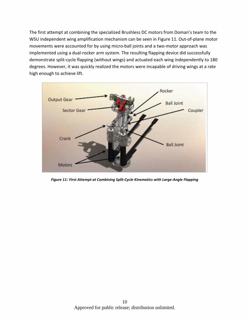
The solution to increase flapping angle while maintaining good torque angles on the rocker arm was to add an additional gearing amplification at the end of the rocker arm, as seen in Figure 11. This also allows the wings to flap without a quick return effect. A diagram of the angles can be found in Figure 12.
10 Approved for public release; distribution unlimited.
The first attempt at combining the specialized Brushless DC motors from Doman’s team to the WSU independent wing amplification mechanism can be seen in Figure 11. Out-of-plane motor movements were accounted for by using micro-ball joints and a two-motor approach was implemented using a dual-rocker arm system. The resulting flapping device did successfully demonstrate split-cycle flapping (without wings) and actuated each wing independently to 180 degrees. However, it was quickly realized the motors were incapable of driving wings at a rate high enough to achieve lift.
Figure 11: First Attempt at Combining Split-Cycle Kinematics with Large-Angle Flapping

11 Approved for public release; distribution unlimited.
Figure 12: Schematic of Combined Gearing
In Figure 13 the oscillation amplification between the four-bar mechanism (blue, red, and purple) to a wing pivot can been seen (black).
Figure 13: 3D Plot of Angles of Each Component during Operation

12 Approved for public release; distribution unlimited.
Finally, a motor survey was conducted to find a high power-to-weight ratio brushless DC motor. The motor position encoders of the original AFRL split-cycle mechanism were stripped and implemented on the back of the new motors. The integration of a dual brushless DC motor and rocker wing amplification mechanism resulted in dramatic increases in lift. In addition, with motor position encoders installed, independent split-cycle control can be used. Though the effectiveness has not been determined for this particular model, in preliminary testing, the device actuation performed correctly. Given the successful control of previous models using the same method, the outlook for successful implementation is very good.
The research performed at WSU resulted in a new flapping mechanism concept, which was the basis of two-wing flapping testing and design at AFRL. A specific area of success was the combination of the high lift-to-weight design produced by WSU with a successful control algorithm at AFRL. The WSU and AFRL combination model in Figure 14 is currently being flight tested and producing 43 grams of lift with an expected vehicle weight of 30 grams (battery included). In 2011, an earlier version of this mechanism was producing 3 grams of lift.
Figure 14: Most Recent Redesign of Combined WSU and AFRL Efforts
Finally, all the parts needed for this new design, including gears and chassis components (Figure 15), were entirely produced at CMAVS.

13 Approved for public release; distribution unlimited.
Figure 15: Components and Parts Produced At CMAVS
3.2 Building Wing Manufacturing Capability
In collaboration with AFRL, wing fabrication was studied by Mervat Elhindi as taught by Ben Perseghetti. Figure 16 displays a 3D print of the wing design attached to a platform. This allows the mold to be filled with silicone to create a negative representation of the wings. An example silicone mold is displayed in Figure 17.

14 Approved for public release; distribution unlimited.
Figure 16: 3D Print of a Wing Design
Figure 17: Silicon Mold to Lay Carbon Fiber Tow
Ms. Elhindi collaborated with Brian Smyers to make silicon molds of all wing designs. She also used the facilities in B24C to make the wings for WPAFB and AFRL. The advantage of creating wings at AFRL was due to the use of a vacuum oven, unavailable at WSU. The vacuum oven was a crucial step in allowing the epoxy to cure properly, thereby providing the carbon fiber spars the desired rigidity. It was proved that without curing the wings in the vacuum oven, the wings were easily broken and too flimsy to flap.
Ms. Elhindi refined the process and made it suitable for designs with small angles. Previously, it was difficult to lay tow involving acute angles in the design. She refined the process to make it suitable for any type of design, regardless of its complexity.
She then created wings for the flapping mechanism devised by 1Lt Zach Goff. A wing example is shown in Figure 18. His mechanism was a two-wing flapping MAV. The design was inspired from wasp wings. Many iterations of this wing were made to prevent breakage. The iterations involved increasing spar thicknesses, which increased the weight of the wing. At a flapping

15 Approved for public release; distribution unlimited.
frequency of 17 Hz, this design was able to lift 26 grams, an amount greater than the vehicle weight. Ms. Elhindi provided wing manufacturing consultation to several AFRL staff members, including 1Lt. Goff, 1Lt. Staples, Isaac Weintraub, Todd Smith and Jaderic Dawson. Instruction was also provided on how to adjust the steps of laying in the tow to tune each wing design.
Figure 18: Wing Design for Goff Mechanism
Ms. Elhindi also used the Bench Test Laboratory to test the wings she created. Although there is a load cell at WSU, she synchronized the load cell in B24C with high-speed cameras to record wing lift at each phase of the flapping cycle. The cameras took images of the wings at various different points during one flapping cycle. It was visible through these images that the wing deforms while under load. These images helped aide alterations in wing designs to have the ability to twist more to increase the lift from the wings. The equipment eventually led to the conclusion that even by slightly altering the wing design, stability of the flap changes, and also lift changes with these variations.
3.3 NATO AVT-184: WSU-Delft Collaboration
We conducted an optimization study of a four-wing flapper, and concluded that a modified wing, wing II (Figure 19 right), with a chord length of 80mm, span-wise length of 190mm and cross-strut pattern S3 (Figure 20) outperformed the original wing, wing I (Figure 19 left). The lift coefficient of wing II increased drastically compared with wing I, and a slight increase of thrust was also observed. The force measurement data was analyzed carefully correlating with the quantitative flow measurement using PIV. It was found that wing II can generate higher momentum of the jet flow at the clapped position. During the whole clap-and-fling motion, it seems the flapping wing benefits from the improved flexibility distribution provided by the additional beam at 30 degree with respect to the leading edge of the wing. The coherent structures of the shedding vortices were also varied as the deformation of the whole wing varied for wing II at each phase angle. The three-dimensional characteristics of the vortex flow structure need to be addressed in future work using a stereoscopic PIV technique.

16 Approved for public release; distribution unlimited.
Figure 19: Two Different Wing Configurations (Left: Wing I, Right: Wing II)
Figure 20: Three Different Cross-Strut Patterns
Both WSU and TU Delft (Delft University of Technology) have done PIV and load cell measurement on MAVs; however, the approach and equipment used are different. The goal of the DelFly experiment was to test Wing I and II at the TU Delft facility to verify the accuracy of our result. There were four major differences between the two experimental setups. First, the wind tunnel at WSU has a closed test section, while at TU Delft, the MAV was measured in an open section wing tunnel (Figure 21). Second, WSU has a 2-D PIV system, while TU Delft is capable of measuring 2-D PIV, stereo PIV and tomographic PIV, so a 3-D flow structure can be readily measured. Given the difficulty of tomographic PIV we decided to measure our MAV using a Stereo PIV system. Third, at WSU the laser sheet direction is parallel to the MAV’s flight direction. The strategy for this alignment was to more clearly measure the flow structure around the wing and to avoid indirect interpretation of flow speed. The disadvantage of this approach was the wing of the MAV still needed to be painted black so the CCD camera would not be damaged by laser reflection. In contrast, TU Delft placed the laser perpendicular to the MAV’s flight direction. This was to avoid the wing reflection and the potential of damaging the CCD camera. With this setup, the laser sheet would have to be placed a distance from the MAV, so the closed wing flow structure would not be measured. The fourth difference related to the method of analyzing data. We used a PIV phase-lock technique, which averaged over a large number of tests at specific phases. TU Delft collected time-series data and by comparing it to the brushless motor output, the different phases could be analyzed.

17 Approved for public release; distribution unlimited.
Figure 21: Open Test Section Wind Tunnel
Due to equipment failure and a lack of understanding of TU Delft’s MAV testing facility, a few changes were made to the experimental approach while at TU Delft. A brushless motor drives the DelFly, and the system was designed to control the vehicle under a given flapping frequency. WSU’s four-wing flapper used a brushed motor; thus, synchronizing the MAV with the TU Delft system was a challenge. We tried different synchronization approaches, but no solutions were found due to the fact that the system was designed for a specific motor. Finally, we abandoned the time-series data collection method and used phase-locked PIV. To do so, magnets were placed into the center gear of the MAV (Figure 22) and a magnet sensor was placed between the metal gears to trigger the PIV system (Figure 23).
Figure 22: Center Gear with Magnets
18 Approved for public release; distribution unlimited.
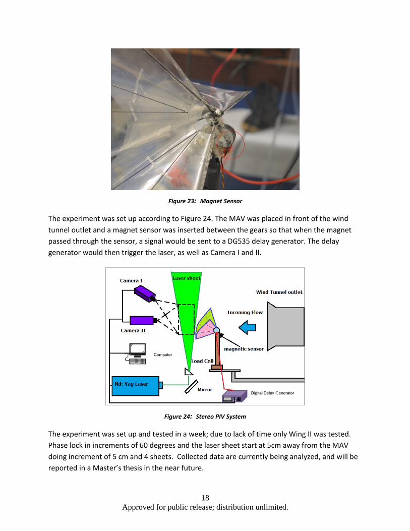
Figure 23: Magnet Sensor
The experiment was set up according to Figure 24. The MAV was placed in front of the wind tunnel outlet and a magnet sensor was inserted between the gears so that when the magnet passed through the sensor, a signal would be sent to a DG535 delay generator. The delay generator would then trigger the laser, as well as Camera I and II.
Figure 24: Stereo PIV System
The experiment was set up and tested in a week; due to lack of time only Wing II was tested. Phase lock in increments of 60 degrees and the laser sheet start at 5cm away from the MAV doing increment of 5 cm and 4 sheets. Collected data are currently being analyzed, and will be reported in a Master’s thesis in the near future.

19 Approved for public release; distribution unlimited.
4.0 Flight Lab Testing
4.1 MAV Configurations Developed
The average Standard model weighs 13g (without a battery), and has a wingspan of 200mm and a length of 175mm (Figure 25). The vehicle uses a 70mAh LiPo battery. The standard model is a four-wing flapping micro air vehicle and uses a clap-and-fling flight method to generate thrust. Specifications are “average,” since all vehicles are hand-crafted.
The average Modified Standard model optimized by PIV data has a wingspan of 190mm and a chord length of 90mm, with an additional spar on the each wing for increased performance. The weight of the Modified Standard model is 12g (without a battery). This model uses a 150mAh LiPo battery.
The average “Big Bird” model, weights 23.1g (without a battery), has a wingspan of 340mm and a length of 270mm average (Figure 26). The vehicle uses a 150mAh battery. The “Big Bird” is a larger model then the Standard model and performs as a four-wing flapping MAV.
The Quadrotor model, weighs 297g with a 2500mAh two cell Lipo battery, and a square dimension of 270mm x 270mm (Figure 27). The quadrotor uses 4 propellers and 4 brushless motors and an Arduino Pro Mini chip to control the motors to execute lift, yaw and roll.
Figure 25: Standard Model with Reflective Tape

20 Approved for public release; distribution unlimited.
Figure 26: “Big Bird” Model with Reflective Tape
Figure 27: Quadrotor with Four Pearl Markers
4.2 Summary Description of Aircraft Flight Tests
All the vehicles tested were flown in the VICON room from January 15th-Febuary 11th, 2013. The configurations, test types, test days, and test durations for all tests are compiled in Table 1.
21 Approved for public release; distribution unlimited.
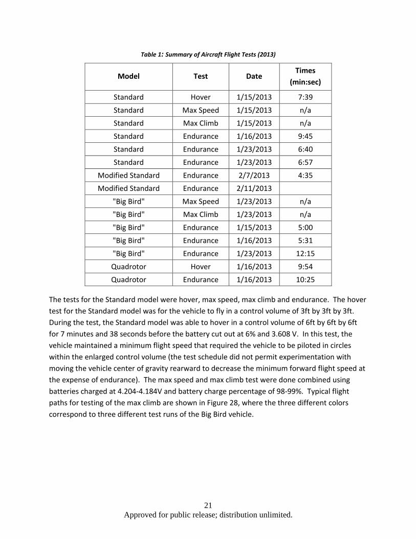
Table 1: Summary of Aircraft Flight Tests (2013)
Model Test Date Times
(min:sec)
Standard Hover 1/15/2013 7:39
Standard Max Speed 1/15/2013 n/a
Standard Max Climb 1/15/2013 n/a
Standard Endurance 1/16/2013 9:45
Standard Endurance 1/23/2013 6:40
Standard Endurance 1/23/2013 6:57
Modified Standard Endurance 2/7/2013 4:35
Modified Standard Endurance 2/11/2013
"Big Bird" Max Speed 1/23/2013 n/a
"Big Bird" Max Climb 1/23/2013 n/a
"Big Bird" Endurance 1/15/2013 5:00
"Big Bird" Endurance 1/16/2013 5:31
"Big Bird" Endurance 1/23/2013 12:15
Quadrotor Hover 1/16/2013 9:54
Quadrotor Endurance 1/16/2013 10:25
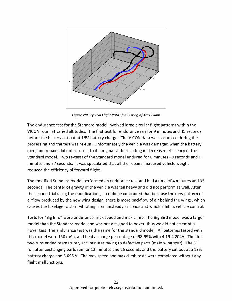
The tests for the Standard model were hover, max speed, max climb and endurance. The hover test for the Standard model was for the vehicle to fly in a control volume of 3ft by 3ft by 3ft. During the test, the Standard model was able to hover in a control volume of 6ft by 6ft by 6ft for 7 minutes and 38 seconds before the battery cut out at 6% and 3.608 V. In this test, the vehicle maintained a minimum flight speed that required the vehicle to be piloted in circles within the enlarged control volume (the test schedule did not permit experimentation with moving the vehicle center of gravity rearward to decrease the minimum forward flight speed at the expense of endurance). The max speed and max climb test were done combined using batteries charged at 4.204-4.184V and battery charge percentage of 98-99%. Typical flight paths for testing of the max climb are shown in Figure 28, where the three different colors correspond to three different test runs of the Big Bird vehicle.
22 Approved for public release; distribution unlimited.
Figure 28: Typical Flight Paths for Testing of Max Climb
The endurance test for the Standard model involved large circular flight patterns within the VICON room at varied altitudes. The first test for endurance ran for 9 minutes and 45 seconds before the battery cut out at 16% battery charge. The VICON data was corrupted during the processing and the test was re-run. Unfortunately the vehicle was damaged when the battery died, and repairs did not return it to its original state resulting in decreased efficiency of the Standard model. Two re-tests of the Standard model endured for 6 minutes 40 seconds and 6 minutes and 57 seconds. It was speculated that all the repairs increased vehicle weight reduced the efficiency of forward flight.
The modified Standard model performed an endurance test and had a time of 4 minutes and 35 seconds. The center of gravity of the vehicle was tail heavy and did not perform as well. After the second trial using the modifications, it could be concluded that because the new pattern of airflow produced by the new wing design, there is more backflow of air behind the wings, which causes the fuselage to start vibrating from unsteady air loads and which inhibits vehicle control.
Tests for “Big Bird” were endurance, max speed and max climb. The Big Bird model was a larger model than the Standard model and was not designed to hover, thus we did not attempt a hover test. The endurance test was the same for the standard model. All batteries tested with this model were 150 mAh, and held a charge percentage of 98-99% with 4.19-4.204V. The first two runs ended prematurely at 5 minutes owing to defective parts (main wing spar). The 3rd run after exchanging parts ran for 12 minutes and 15 seconds and the battery cut out at a 13% battery charge and 3.695 V. The max speed and max climb tests were completed without any flight malfunctions.
x
-5
0
5y
-6-4
-20
24
z
0
1
2
3
4
5
6

23 Approved for public release; distribution unlimited.
A test for the Quadrotor was hover and endurance. The quadrotor used a 2500 mAh LiPo 2 cell battery, with a 99% charge and 4.150 V on both cells. The objective for the quad rotor hover test was to stay with in a specific volume of 3 cubic feet. The quad rotor was able to fly with in the guidelines of the 3 cubic feet for 9 minutes and 54 seconds. The battery percentage was at 20% after the flight and 3.74V for both cells. The reason for the premature battery cut out was because one of the speed controllers might have been set to drop out at a certain battery voltage and cause the quad rotor to lose its hover. The endurance test was taken as the start of the hover test which resulted in 10 minutes and 25 seconds.
4.3 Vehicle Motion Capture
The MAVs were tracked using VICON. Reflective tape and Pearl Markers from B&L Engineering were used on all models as points of tracking. The standard model, modified standard, and “big bird” model had 8 reflectors on each, 2 on the rudder, 2 for the elevator, 2 for the wings, one for the nose and one for the fuselage. The Quadrotor had 4 reflectors one for each of the four rotors. This allowed us to track the MAV in the VICON room to verify the results of our tests.
4.4 Qualitative Findings
The result from the flight test specifies the strengths in the MAVs. The standard model is maneuverable and fast, while “Big Bird” can fly for longer periods and climb faster, and the quadrotor shows prowess in hovering very easily. Each model can be altered to perform a certain way, for example, if the standard model were to increase its hovering ability the center of gravity would need to be moved back to towards the tail, and for speed, center of gravity would be shifted to the nose. Minor corrections in these areas can vastly affect the performance of the vehicle. As for the modified standard model because of the wings design further study needs to be invested in adapting the vehicle’s build to support the compatibility, in order to obtain significant data.
Vehicle Hover Time(s) Max Climb (m/s) Max Speed (m/s) Endurance (s)
Standard 458 1.162 7.271870186 585
Mod-Standard 275
Big Bird N/A 1.85375 5.030046285 735
Quadrotor 594 -- -- 625
Table 2: Comparison of Different MAV Configurations for Four Test Scenarios

24 Approved for public release; distribution unlimited.
5.0 Technical Achievement
5.1 Wing Designs and Optimization
One of the major thrusts of CMAVS has been wing design and analysis for flapping wing MAVs. Carbon fiber tissue was first used as a membrane for artificial wings. This material proved to be inefficient due to its weight after applying epoxy to the tissue. The study then shifted to the venial layout of the wings. Mylar is a lightweight material that is flexible and was substituted for the carbon fiber tissue. A systematic process was developed for wing fabrication using Mylar (.22 µm) for the membrane and carbon fiber tow for the venial layout. The wing design can be created using CAD software and printed using a rapid prototyping machine. The print features a positive mold: a negative mold is made from the printed version using silicone. Epoxy impregnated carbon fiber tow is laid into the groves of the silicone with pre-coordinated thicknesses and placed in a vacuum oven for 2 hours at 350 degrees Fahrenheit. Once the epoxy has cured the wings are taken out of the mold and glued onto 0.22 µm Mylar on each side. After mastering the process of wing prototyping, several insect wings were studied to find correlations between wing morphology and performance.
By investigating insect wing designs, the Comstock Needham System was found and studied. It was created in the 1800s and describes the relationship between venial structures in different insects. This system states that each insect wing features a leading edge (the costa or subcosta) that does not branch into smaller veins. Some insects feature both of these veins, others only feature one. Underneath the un-branched veins lays one to three longitudinal veins that branch out across the wing. Some insects have a final un-branched vein below the branched veins.

25 Approved for public release; distribution unlimited.
Figure 29: Comstock-Needham Based Morphology
From this description and these guidelines, a preliminary wing was created (Figure 29). This wing features a costa and a subcosta. The leading edge features twisted carbon fiber tow to provide extra rigidity without an increase in the weight. This wing design was too rigid compared to insect wings. Insect wings passively deform during the flapping cycle, but the preliminary design, constructed as described above, lacked this natural response.
This observation was the motivation behind comparing multiple insect wings, including the bumblebee, cicada, and wasp. At first glance, these wings appear to be unrelated in venial structure. It was found that each of these insects belong to different families but feature similar design structure within equivalent regions. Figure 30 displays wings from each of the three insects. Region II displays the most common feature observed in each case; the connection point between the costa and the subcosta at roughly mid-span, which is referred to as the “knot.” At this conjunction, there is an abrupt transition between the thick wing root and thin wing tip. The veins attached at the knot satisfy the Comstock-Needham System: it features the subcosta; un-branched, and below the costa. Due to the tapering of the leading edge, the wing is stiff toward the root and flexible toward the tip. This observation was linked to insect wing deformation during flight. The combination of the tapering effect and the knot placed at the point of the leading edge, where the most distinguishable difference in venial thickness exists, allows for wing deformation during the flapping cycle. The knot was also linked to wing

26 Approved for public release; distribution unlimited.
deformation because it allows the wing to bend at the knot, forming a concavity along the subcosta structure.
Figure 30: Insect Wing Comparison: (Top) Bumblebee; (Center) Cicada; (Bottom) Wasp
Another common characteristic of these wings is the tendency to maintain a heavy structure closest to the wing root and transition the layout into a softer structure as the veins approach the wing tip. This feature aids in wing deformation because the tip is flexible enough to bend, but strong enough to create air flow to thrust the wing upward, as shown in Figure 31.
Figure 31: Flapping of Artificial Wings
Carbon fiber tow was tested to compare various thicknesses. Each thickness, 1k, 2k, 3k, and three strands of 1k braided faced bending tests. All cross sectional areas were assumed to be

27 Approved for public release; distribution unlimited.
rectangular and the carbon rods were bent in the direction of the smallest area moment. Placing the different sized rods on a stand, and placing the stand on a load cell was the setup of the experiment. Each rod had 1, 2, 3, and 4 grams of weight added to the rod. A grid was placed behind the stand to measure the deflection with corresponding weights. 3k tow unbraided tow was 81% more rigid than three strands of braided 1k tow, (totaling to 3k tow), when 3 grams were placed on the rods. 2k tow was 84% more rigid than 1k tows when two grams were places on each of the rods.
Through the inspiration gathered from the Comstock Needham System, the morphological similarities of the insects, and the carbon fiber testing results, a new wing design was conceived. The design displayed shown in Figure 32 contains a costa, subcosta, radius and cubitus. The radius contains two branches that spread out to cover the surface area of the wing at the tip. The cubitus lines the bottom edge of the wing.
Figure 32: Structure of a Wing
Experiments were performed with a wing fabricated from the new design. Slight changes were made to the wings to observe the effects of small structural changes on the flapping frequency and lift. Four separate wings were created from the changes and these are displayed in Figure 33.

28 Approved for public release; distribution unlimited.
Figure 33: Optimization of Wing Designs
The letter in the name of each wing represents the spar, while the number represents the percent displacement of the spar closer to the root. As shown in Figure 34, the A15 wing had a higher flapping frequency than the A10 wing when high-speed videos were taken and compared next to each other. The A15 wing also had 2g more lift than the A10 wing. The B10 wing had a higher flapping frequency than the B05 wing when compared side by side under high-speed video. The B10 wing also had 3g more lift than the B05 wing. Figure 34 shows the lift of each wing at power inputs of 4 and 5 volts when the speed controlled was run maximally.
Figure 34: Experimental Comparison of Different Wing Designs

29 Approved for public release; distribution unlimited.
5.2 Miniaturization of MAV Designs
An on-going project consisted of preliminary design of a miniature MAV to weigh 4g. CMAVS specialized in making technological advances in micro machining (e.g., see the micro gear train shown in Figure 35) to further reduce MAV dimensions and increase the overall reliability of MAVs. To increase reliability, new gear trains were redesigned and machined. The new design utilizes all metal gears vs. the previous plastic gears, which limited parts lifetime owing to material failure. In this process, various machines were used together in a series of machining techniques in order to create 3D gears from the 2D machines we operate. Efforts to further the miniaturization process were also taken, including finding sources for more advanced micro receivers and electronics.
Figure 35: Micro Gearing and Assembling
The major achievement of CMAVS was the “Mini MAV” 4 g model, shown in Figure 36. With design of this model now completed (current stage), the model is flying very well. Work is not done on this miniature model; further research and modifications are anticipated. The current design involved outfitting the bird with all new and improved electronics. Other small modifications were made to the airframe as well.
Figure 36: Mini MAV (4 g)

30 Approved for public release; distribution unlimited.
In conjunction with vehicle miniaturization, we continued research in metal gears. New gears were designed and cut, removing more material to reduce weight. There is currently a flying metal gear bird now at the time of report preparation; work in metal gears will continue in parallel with the Mini MAV testing to see if our machines are capable of producing metal gears for Mini MAV. In addition to increased reliability, these gears will also decrease noise and friction compared to the original plastic gears.
Following the recent experience with metal gear fabrication, a deeper examination is being conducted into the manufacturing of these gears. Due to lack of 5-axis machinery, creating these three-dimensional gears is especially difficult. A method for machining was then created using three machines in a series to create the three dimensional design as shown in Figure 37. Following machine and testing of the gears, it became evident that the needed tolerances were not met with this technique due to the amount of slop and wobble that the gears illustrated when the gears were on a frame.
Figure 37: Manufacturing of 3D Gear System
Utilizing a CNC mill along with the CMAVS CNC EDM machine was the next solution examined. After learning new machining techniques with this equipment, the new metal gears were manufactured and were found to perform much better. After mastering the fabrication of larger gears, the EDM machine was tested to its limit using the current set up of the machine. The determined limit of the machine was the production of gears greater than 12mm in diameter (with a modulus of 0.38 – a geometric parameter of gears – using the 0.010” wire currently setup on the machine). After learning the new limits of the current set up, we still desire to cut metal gears for the 4g design, which utilizes gears with a modulus of 0.25 and diameters of 4mm.
The CMAVS EDM machine was then switched and reconfigured to use smaller 0.006” wire, which would allow cutting a smaller radius. After the machine was converted over with the new parts, test cuts began. It became quickly evident that the new thinner wire was very difficult to cut without breaking the wire. After contacting the company to recommend a power
31 Approved for public release; distribution unlimited.
setting, they could not offer a solution to the situation due to no one using the small wire and cutting such precision parts in the world. The following week included extensive work and calculations with power, current and many more inputs that control the machine. After extensive reprograming of the machine, it finally began cutting with the new setup efficiently and effectively. With the machine working to its tolerance limit, a new test was conducted to see exactly how small the gears could be machined.
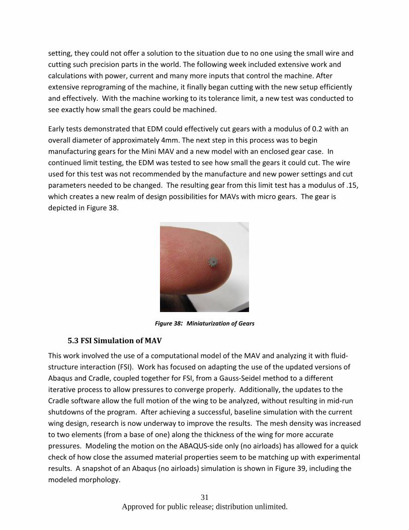
Early tests demonstrated that EDM could effectively cut gears with a modulus of 0.2 with an overall diameter of approximately 4mm. The next step in this process was to begin manufacturing gears for the Mini MAV and a new model with an enclosed gear case. In continued limit testing, the EDM was tested to see how small the gears it could cut. The wire used for this test was not recommended by the manufacture and new power settings and cut parameters needed to be changed. The resulting gear from this limit test has a modulus of .15, which creates a new realm of design possibilities for MAVs with micro gears. The gear is depicted in Figure 38.
Figure 38: Miniaturization of Gears
5.3 FSI Simulation of MAV
This work involved the use of a computational model of the MAV and analyzing it with fluid-structure interaction (FSI). Work has focused on adapting the use of the updated versions of Abaqus and Cradle, coupled together for FSI, from a Gauss-Seidel method to a different iterative process to allow pressures to converge properly. Additionally, the updates to the Cradle software allow the full motion of the wing to be analyzed, without resulting in mid-run shutdowns of the program. After achieving a successful, baseline simulation with the current wing design, research is now underway to improve the results. The mesh density was increased to two elements (from a base of one) along the thickness of the wing for more accurate pressures. Modeling the motion on the ABAQUS-side only (no airloads) has allowed for a quick check of how close the assumed material properties seem to be matching up with experimental results. A snapshot of an Abaqus (no airloads) simulation is shown in Figure 39, including the modeled morphology.

32 Approved for public release; distribution unlimited.
Figure 39: Abaqus Representation of Bio-Inspired Wing
This saves significant time, since running the new, coupled FSI analysis takes approximately 5 days to look at just a couple seconds of flight time. Work is continuing to get the motion closer to that seen experimentally, which will allow the lift force to be accurately calculated later using FSI. The final steps once the material properties have been finalized will be to look into the different experimental wing models as they are being designed. As a majority of the settings have been setup through the learning process of using FSI, new models simply require changing the mesh once the solid model has been created and imported. Additionally, parametric studies will be looking into different flapping frequencies and even changing materials to compare lift generation. The pressure contours during a few times steps are shown in Figure 40.

33 Approved for public release; distribution unlimited.
Figure 40: Pressure Contours in SC/Tetra from FSI Analysis
5.4 Development of a Continuously Variable Transmission (CVT)
A continuous variable transmission allows for a gear system to have essentially an infinitesimal amount of gear ratios without shifting of gears. The objective for experimenting into a CVT design was to develop a mechanism for independently controlled wings on an MAV. The first step was to design a mechanism and build a working model. Research on CVT designs of the past and present were considered; the cone, disk, toroidal, and magnetic CVTs. The cone CVT was selected for further development based on the openness of its mechanism. The idea was to apply two out shafts to one input shaft, meaning only one motor would be needed, as shown in Figure 41. The first model was drafted in Solidworks and printed out using the rapid prototype printer. Once the proof of concept was confirmed, a smaller model was developed to make the design applicable to a flight-weight system. As shown, the prototype allowed for two independently controlled output shafts; i.e., two different speeds of output rotation for one input rotation from the motor. Changes were made for further size reduction, various materials were experimented with, and alternative configurations were examined to increase friction and supply more torque. A triangular formation was used on the cone positions for a more compact build. The amount of friction was increased by creating threads on the cones surface.

34 Approved for public release; distribution unlimited.
Figure 41: Large CVT Prototype
The smaller model of the CVT design was reduced to roughly an eighth of the original prototype size, as shown in Figure 42. The limiting factor for how much the CVT design could be miniaturized was the size of certain COTS components: the O-rings and bearings; 3x2 metric O-ring and 1X3X1 metric bearing. The smaller model was tested using a DC power source and the motor ran efficiently at 2.7 V. Testing the smaller prototype allowed for structural weaknesses to be discovered, indicating that the design trades between strength and size.
Figure 42: Comparison of the Large and Small CVT Prototypes
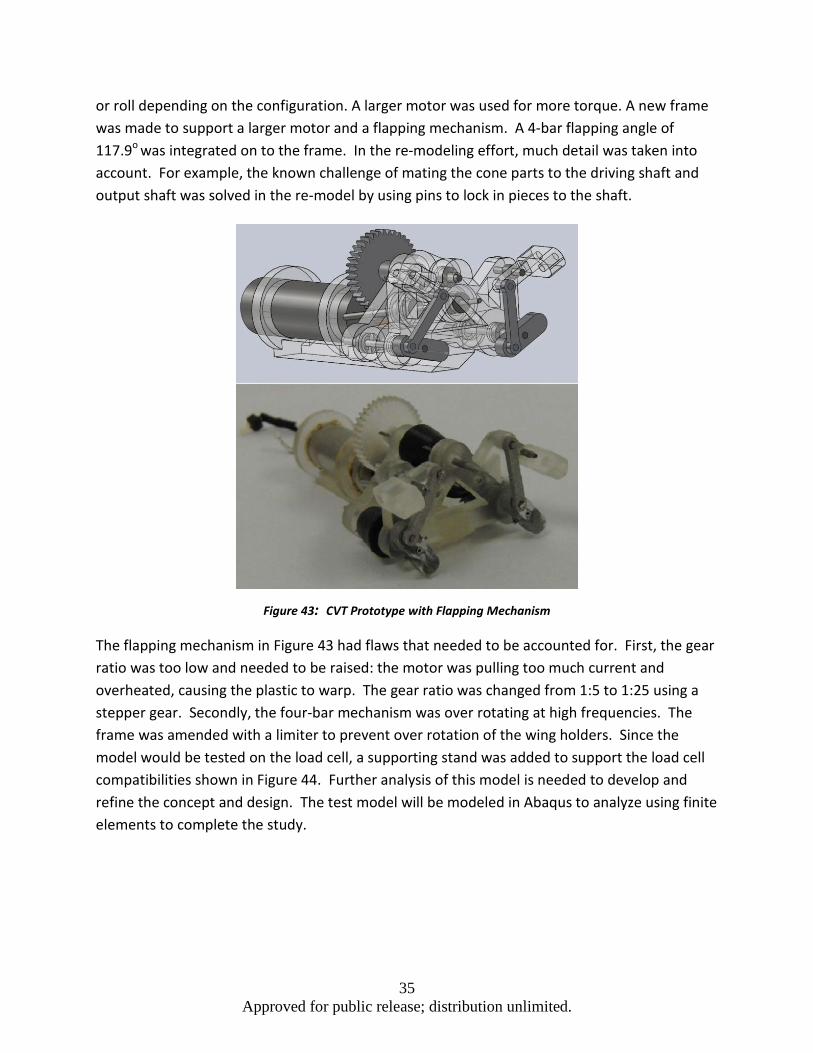
After building and running the smaller CVT prototype, the next phase was to introduce a flapping mechanism, as shown in Figure 43. Remodeling of the newest model eliminated the threads on the cone and used a rubber coating to increase the friction; three layers of the rubber coating were used. The plastic for the bearing was remodeled to withstand more stress. The cone size was remodeled to be 60% the size of the small prototype model, since the difference in rotation between the two rotors does not need to be very large to generate yaw
35 Approved for public release; distribution unlimited.
or roll depending on the configuration. A larger motor was used for more torque. A new frame was made to support a larger motor and a flapping mechanism. A 4-bar flapping angle of 117.9o was integrated on to the frame. In the re-modeling effort, much detail was taken into account. For example, the known challenge of mating the cone parts to the driving shaft and output shaft was solved in the re-model by using pins to lock in pieces to the shaft.
Figure 43: CVT Prototype with Flapping Mechanism
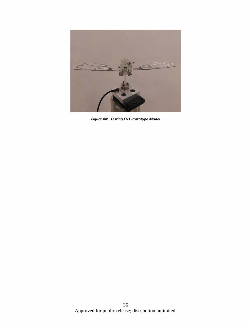
The flapping mechanism in Figure 43 had flaws that needed to be accounted for. First, the gear ratio was too low and needed to be raised: the motor was pulling too much current and overheated, causing the plastic to warp. The gear ratio was changed from 1:5 to 1:25 using a stepper gear. Secondly, the four-bar mechanism was over rotating at high frequencies. The frame was amended with a limiter to prevent over rotation of the wing holders. Since the model would be tested on the load cell, a supporting stand was added to support the load cell compatibilities shown in Figure 44. Further analysis of this model is needed to develop and refine the concept and design. The test model will be modeled in Abaqus to analyze using finite elements to complete the study.
36 Approved for public release; distribution unlimited.
Figure 44: Testing CVT Prototype Model

37 Approved for public release; distribution unlimited.
6.0 Transition to the Future As MAV research is no longer an AFRL focus area, the CMAVS Cooperative Research Agreement was not extended. A proposal was developed to transform CMAVS into an advanced manufacturing Center.
Together with seven companies, Wright State University proposed a 22-month project to qualify and certify the use of additive manufacturing for micro-devices. The research will focus on qualifying the additive manufacturing (AM) and its comparison with the conventional subtractive manufacturing for a series of micro systems using an industrial checking standard. A highly-select group of undergraduate and graduate students will be hired to work on the project. In this approach, the students will be exposed to a range of advanced manufacturing techniques currently available in the industrial setting, including state-of-the-art additive manufacturing. Students will be organized into teams that will map out different approaches and control parameters to:
1. Optimize various control parameters such as deposition rate, energy input, etc. To improve the quality of micro-parts using the additive manufacturing,
2. Define the range of applicability of the additive manufacturing in comparison to the subtractive manufacturing, and,
3. Address areas for improvement in the field of additive manufacturing for micro-devices.
Another goal of the current project is to prepare future engineers for the job market needs in the additive manufacturing sector. By combining the PBL approach, with state-of-the-art additive manufacturing techniques, and the training of students through work-based learning opportunities with partner companies, all the WSU students will be exposed to an innovation-driven, production-oriented engineering culture in which real-world problems can be solved.
Figure 45: Complex Shape Designs Using Additive Manufacturing
(Manufacturing Complex Micro Parts With Micro Laser-Sintering, Joachim Gobner, EOS Gmbh)

38 Approved for public release; distribution unlimited.
Figure 46: The Lattice Sub-Microstructure
(Phenix Systems)
The development of the additive manufacturing has revolutionized the way new devices are designed, since this approach is capable of creating highly complex objects that would be difficult, if not impossible, to produce using conventional manufacturing techniques. For example, it is now possible to make combustion chamber with very complex fuel micro-duct distribution embedded inside the injection nozzle, or design intricate microscopic surface and sub-surface structures on a substrate to increase the wetted area (see Figure 45(a) and (b), respectively). Due to the combination of the rapid prototyping capability and complex-geometry handling nature of the additive manufacturing, engineers are able to design innovative products with a rapid turnaround time at lower costs. As a result, the opportunity has opened up a new dimension in structure designs for Air Force applications, including functionally graded structures. Functionally graded structures belong to a class of advanced materials characterized by variation in properties with position. The purpose is to satisfy specific functional requirements of components, such as the controlled variation of stiffness to change the damping characteristics of the part. Functionally-graded structures can be created by intercalating different material combinations, such as metal/metal or metal/non-metal in the molten or semi-solid state, and embedding complex micro-structures within the overall structure (see Figure 46).
39 Approved for public release; distribution unlimited.
7.0 Conclusions The CMAVS project provided the following outcomes:
1. The project based learning experiments, as applied to MAV research and development, demonstrated a positive outcome. We observed that students were not only more successful in academic studies, but were able to secure good engineering jobs after graduation.
2. The collaboration between the WSU and AFRL MAV groups accelerated the design and manufacturing of new MAV configurations.
3. The MAVs were tested in the AFRL indoor flight lab. With this facility, the performance characteristics of four different MAV configurations were successfully quantified.
4. A number of goals and milestones were achieved including experimental wing design and optimization, miniaturization of MAV, FSI simulation and CVT development.
Our aim is to move forward with a transformation of CMAVS to an advanced manufacturing Center, and serve a wider range of Air Force technology development needs.

40 Approved for public release; distribution unlimited.
List of Symbols, Abbreviations, and Acronyms Acronym Definition
AFRL Air Force Research Laboratory AM Additive Manufacturing CMAVS Center for Micro Air Vehicle Studies CTV Continuously Variable Transmission DCASS Dayton-Cincinnati Aerospace Sciences Symposium FSI Fluid-Structure Interaction MAV Micro Air Vehicles PBL Project Based Learning TU Delft Delft University of Technology WSU Wright State University