agrément certificate 06/4347 - quad-lock for in-situ dense concrete for use in loadbearing ... with...
TRANSCRIPT
Page 1 of 18
TECHNICAL APPROVALS FOR CONSTRUCTION
APPROVAL
INSPECTION
TESTING
CERTIFICATION
Quad-Lock Building Systems7398 - 132nd StreetSurreyBritish Columbia V3W 4M7CanadaTel: +1(604) 590 3111 Fax: +(604) 590 8412e-mail: [email protected]: www.quadlock.co.uk
British Board of Agrément tel: 01923 665300Bucknalls Lane fax: 01923 665301Watford e-mail: [email protected] WD25 9BA website: www.bbacerts.co.uk©2013
The BBA is a UKAS accredited certification body — Number 113. The schedule of the current scope of accreditation for product certification is available in pdf format via the UKAS link on the BBA website at www.bbacerts.co.uk
Readers are advised to check the validity and latest issue number of this Agrément Certificate by either referring to the BBA website or contacting the BBA direct.
QUAD-LOCK BUILDING SYSTEMS
QUAD-LOCK INSULATING CONCRETE FORMWORK (ICF) SYSTEMQUAD-LOCK INSULATING CONCRETE FORMWORK (ICF) SYSTEM
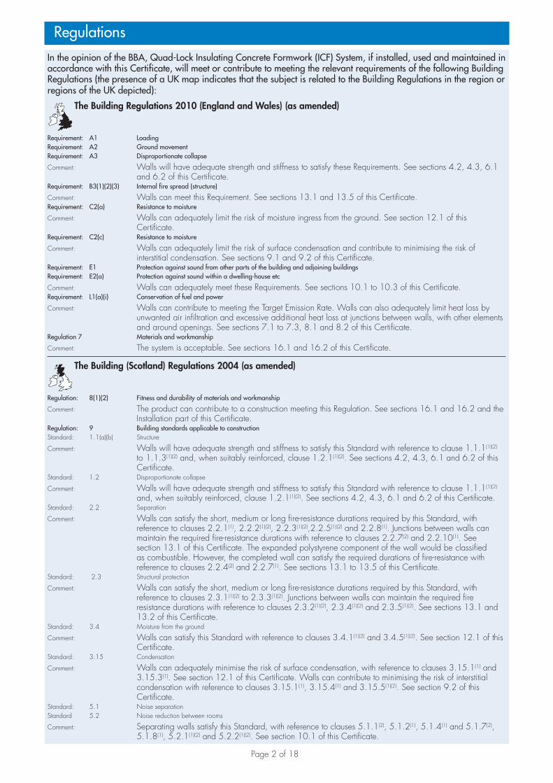
This Agrément Certificate Product Sheet(1) relates to Quad-Lock Insulating Concrete Formwork (ICF) System, comprising expanded polystyrene panels with high-density polyethylene interconnecting spacers. The system provides permanent formwork for in-situ dense concrete for use in loadbearing and nonloadbearing, internal or external and separating straight or curved walls in dwellings and in buildings of similar occupancy to contribute to the thermal insulation of a construction.(1) Hereinafter referred to as ‘Certificate’.
CERTIFICATION INCLUDES:• factors relating to compliance with Building Regulations
where applicable• factors relating to additional non-regulatory information
where applicable• independently verified technical specification• assessment criteria and technical investigations• design considerations• installation guidance• regular surveillance of production• formal three-yearly review.
KEY FACTORS ASSESSEDStructural performance — the system components have adequate strength to resist the loads associated with installation loading (see section 6).Thermal performance — the system contributes to the overall thermal performance of the wall construction (see section 7).Risk of condensation — walls, openings and junctions with other elements will adequately limit the risk of surface condensation (see section 9).Sound insulation — separating and internal walls with a minimum concrete core density and detailing stated in this Certificate will provide sufficient sound resistance (see section 10).Behaviour in relation to fire — the concrete walls formed from the system provide fire resistance when designed in accordance with BS 8110-2 : 1985 or BS EN 1992-1-2 : 2004 (see section 13).Durability — the system components are durable (see section 16).
Agrément Certificate06/4347
Product Sheet 1
The BBA has awarded this Certificate to the company named above for the system described herein. This system has been assessed by the BBA as being fit for its intended use provided it is installed, used and maintained as set out in this Certificate.
On behalf of the British Board of Agrément
Date of First issue: 23 July 2013 Brian Chamberlain Claire Curtis-Thomas
Originally certificated on 13 July 2006 Head of Approvals — Engineering Chief Executive
Page 2 of 18
In the opinion of the BBA, Quad-Lock Insulating Concrete Formwork (ICF) System, if installed, used and maintained in accordance with this Certificate, will meet or contribute to meeting the relevant requirements of the following Building Regulations (the presence of a UK map indicates that the subject is related to the Building Regulations in the region or regions of the UK depicted):
The Building Regulations 2010 (England and Wales) (as amended)
Requirement: A1 LoadingRequirement: A2 Ground movementRequirement: A3 Disproportionate collapse
Comment: Walls will have adequate strength and stiffness to satisfy these Requirements. See sections 4.2, 4.3, 6.1 and 6.2 of this Certificate.
Requirement: B3(1)(2)(3) Internal fire spread (structure)
Comment: Walls can meet this Requirement. See sections 13.1 and 13.5 of this Certificate.Requirement: C2(a) Resistance to moisture
Comment: Walls can adequately limit the risk of moisture ingress from the ground. See section 12.1 of this Certificate.
Requirement: C2(c) Resistance to moisture
Comment: Walls can adequately limit the risk of surface condensation and contribute to minimising the risk of interstitial condensation. See sections 9.1 and 9.2 of this Certificate.
Requirement: E1 Protection against sound from other parts of the building and adjoining buildingsRequirement: E2(a) Protection against sound within a dwelling-house etc
Comment: Walls can adequately meet these Requirements. See sections 10.1 to 10.3 of this Certificate.Requirement: L1(a)(i) Conservation of fuel and power
Comment: Walls can contribute to meeting the Target Emission Rate. Walls can also adequately limit heat loss by unwanted air infiltration and excessive additional heat loss at junctions between walls, with other elements and around openings. See sections 7.1 to 7.3, 8.1 and 8.2 of this Certificate.
Regulation 7 Materials and workmanship
Comment: The system is acceptable. See sections 16.1 and 16.2 of this Certificate.
The Building (Scotland) Regulations 2004 (as amended)
Regulation: 8(1)(2) Fitness and durability of materials and workmanship
Comment: The product can contribute to a construction meeting this Regulation. See sections 16.1 and 16.2 and the Installation part of this Certificate.
Regulation: 9 Building standards applicable to constructionStandard: 1.1(a)(b) Structure
Comment: Walls will have adequate strength and stiffness to satisfy this Standard with reference to clause 1.1.1(1)(2) to 1.1.3(1)(2) and, when suitably reinforced, clause 1.2.1(1)(2). See sections 4.2, 4.3, 6.1 and 6.2 of this Certificate.
Standard: 1.2 Disproportionate collapse
Comment: Walls will have adequate strength and stiffness to satisfy this Standard with reference to clause 1.1.1(1)(2)
and, when suitably reinforced, clause 1.2.1(1)(2). See sections 4.2, 4.3, 6.1 and 6.2 of this Certificate.Standard: 2.2 Separation
Comment: Walls can satisfy the short, medium or long fire-resistance durations required by this Standard, with reference to clauses 2.2.1(1), 2.2.2(1)(2), 2.2.3(1)(2),2.2.5(1)(2) and 2.2.8(1). Junctions between walls can maintain the required fire-resistance durations with reference to clauses 2.2.7(2) and 2.2.10(1). See section 13.1 of this Certificate. The expanded polystyrene component of the wall would be classified as combustible. However, the completed wall can satisfy the required durations of fire-resistance with reference to clauses 2.2.4(2) and 2.2.7(1). See sections 13.1 to 13.5 of this Certificate.
Standard: 2.3 Structural protection
Comment: Walls can satisfy the short, medium or long fire-resistance durations required by this Standard, with reference to clauses 2.3.1(1)(2) to 2.3.3(1)(2). Junctions between walls can maintain the required fire resistance durations with reference to clauses 2.3.2(1)(2), 2.3.4(1)(2) and 2.3.5(1)(2). See sections 13.1 and 13.2 of this Certificate.
Standard: 3.4 Moisture from the ground
Comment: Walls can satisfy this Standard with reference to clauses 3.4.1(1)(2) and 3.4.5(1)(2). See section 12.1 of this Certificate.
Standard: 3.15 Condensation
Comment: Walls can adequately minimise the risk of surface condensation, with reference to clauses 3.15.1(1) and 3.15.3(1). See section 12.1 of this Certificate. Walls can contribute to minimising the risk of interstitial condensation with reference to clauses 3.15.1(1), 3.15.4(1) and 3.15.5(1)(2). See section 9.2 of this Certificate.
Standard: 5.1 Noise separationStandard 5.2 Noise reduction between rooms
Comment: Separating walls satisfy this Standard, with reference to clauses 5.1.1(2), 5.1.2(1), 5.1.4(1) and 5.1.7(2), 5.1.8(1), 5.2.1(1)(2) and 5.2.2(1)(2). See section 10.1 of this Certificate.
Regulations
Page 3 of 18
Standard: 6.1(b) Carbon dioxide emissionStandard: 6.2 Building insulation envelope
Comment: The system will enable, or contribute to enabling, a wall to meet these Standards, with reference to clauses 6.1.1(1)(2), 6.1.4(1), 6.1.5(1), 6.2.1(1)(2), 6.2.3(1), 6.2.4(1)(2), 6.2.5(1)(2), 6.2.6(2) and 6.2.7(2). See sections 7.1 to 7.3, 8.1 and 8.3 of this Certificate.
Standard: 7.1(a)(b) Statement of sustainability
Comment: The product can contribute to meeting the relevant requirements of Regulation 9, Standards 1 to 6 and therefore will contribute to a construction meeting a bronze level of sustainability as defined in this Standard. In addition, the product can contribute to a construction meeting a higher level of sustainability as defined in this Standard, with reference to clauses 7.1.4(1)(2) [Aspects 1(1)(2) and 2(1)], 7.1.6(1)(2) [Aspects 1(1)(2) and 2(1)] and 7.1.7(1)(2) [Aspect 1(1)(2)].
Regulation: 12 Building standards applicable to conversions
Comment: All comments given for these systems under Regulation 9, Standards 1 to 6 also apply to this Regulation, with reference to clause 0.12.1(1)(2) and Schedule 6(1)(2).
(1) Technical Handbook (Domestic). (2) Technical Handbook (Non-Domestic).
The Building Regulations (Northern Ireland) 2012
Regulation: 23(a)(i)(iii)(b) Fitness of materials and workmanship
Comment: The product is acceptable. See sections 16.1 and 16.2 of this Certificate.Regulation: 28 Resistance to moisture and weather
Comment: Walls can adequately limit the risk of moisture ingress from the ground. See section 12.1 of this Certificate.
Regulation: 29 Condensation
Comment: Walls can contribute to minimising the risk of interstitial condensation. See sections 9.1 and 9.2 of this Certificate.
Regulation: 30 Stability
Comment: Walls will have adequate strength and stiffness to satisfy this Regulation. See sections 4.2, 4.3 and 6.1 of this Certificate
Regulation: 31 Disproportionate collapse
Comment: Walls, when suitably reinforced, will have adequate strength and stiffness to satisfy this Regulation. See sections 4.2, 4.3, 6.1 and 6.2 of this Certificate.
Regulation: 35(1)(2)(3) Internal fire spread — Structure
Comment: Walls can satisfy this Regulation. See sections 13.1 and 13.5 of this Certificate.Regulation: 39(a)(i) Conservation measuresRegulation: 40(2) Target carbon dioxide Emissions Rate
Comment: Walls will meet the requirements of the Elemental Method for limiting heat loss. See sections 7.1 to 7.3 of this Certificate. Walls can also adequately limit heat loss by unwanted air infiltration and excessive additional heat loss around openings. See sections 8.1 and 8.2 of this Certificate.
Regulation: 49 Protection against sound from other parts of the building and from adjoining buildingsRegulation: 50(a)(b) Protection against sound within a dwelling or room for residential purposesRegulation: 51 Reverberation in the common internal parts of a buildings containing flats or rooms for residential purposes
Comment: Separating walls can satisfy this Regulation. See section 10.1 of this Certificate.
Construction (Design and Management) Regulations 2007Construction (Design and Management) Regulations (Northern Ireland) 2007
Information in this Certificate may assist the client, CDM co-ordinator, designer and contractors to address their obligations under these Regulations.See section: 3 Delivery and site handling (3.4) of this Certificate.
Additional Information
NHBC Standards 2013NHBC accepts the use of Quad-Lock Insulating Concrete Formwork (ICF) System, provided it is installed, used and maintained in accordance with this Certificate, in relation to NHBC Standards, Chapter 2.1 Concrete and its reinforcement.
CE markingThe Certificate holder has taken the responsibility of CE marking the products in accordance with ETAG 009.
Page 4 of 18
Technical Specification
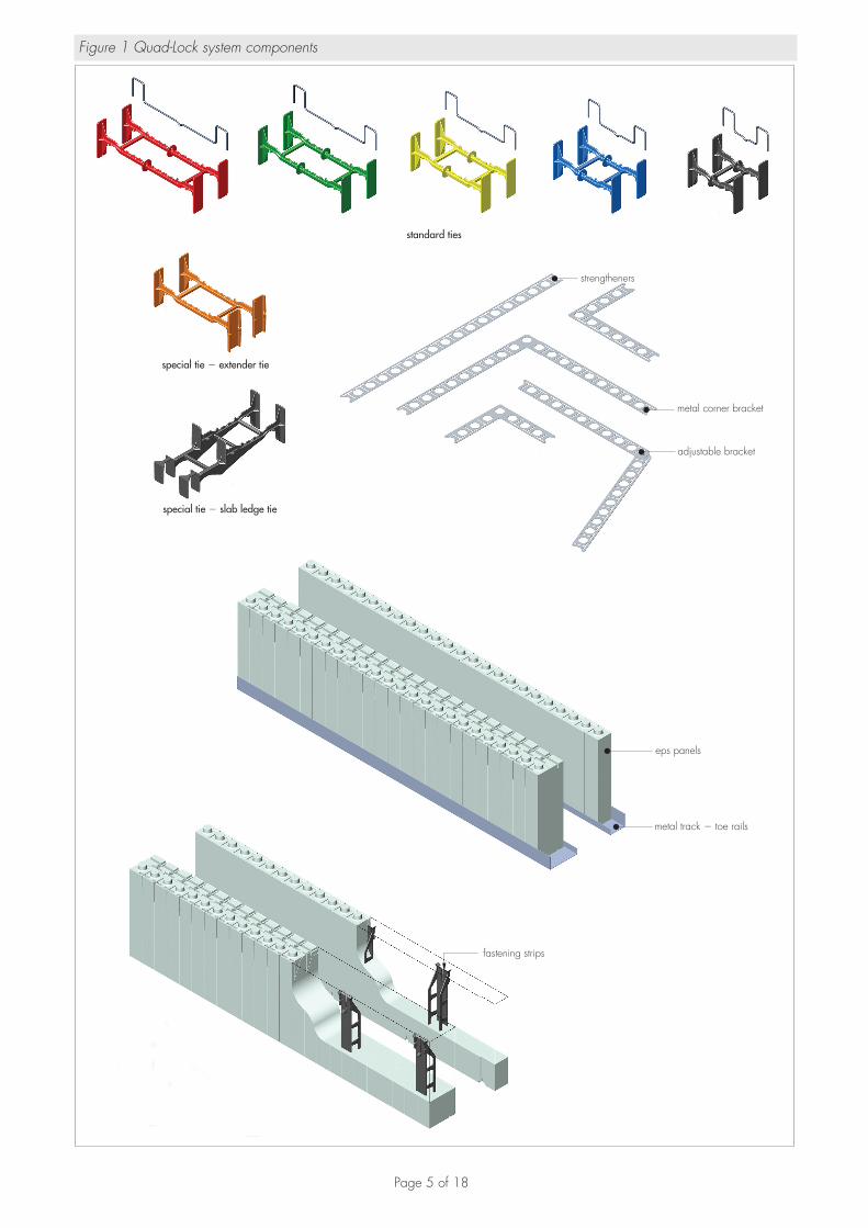
1 Description1.1 The Quad-Lock Insulating Concrete Formwork (ICF) System consists of expanded polystyrene (EPS) panels, high-density polyethylene interconnecting ties, wire top ties, metal tracks (toe rails) and metal corner brackets.
1.2 The components in detail of the system (see Figure 1) are:EPS panels — manufactured from high-density, fire-retardant expanded polystyrene beads in thicknesses of 57 mm and 108 mm. The EPS panels have a nominal density of 30 kg·m–3 (for the 57 mm panel) and 24 kg·m–3 (for the 108 mm panel). An interlocking arrangement is incorporated into the top and bottom of each panel to facilitate the formation of a tight joint. Slots at 51 mm centres are also incorporated in the top and bottom of each panel to receive the plastic spacers. Grooves are moulded into the outside face of each panel to indicate the position of the tie flanges. An internal vertical rebate is also provided to form the wall corners. The vertical ends of the panels are smooth.
Fastening strips (optional) — 38 mm wide Acrylonitrile butadiene styrene (ABS) plastic vertical strips moulded into the panels every 305 mm. These may be incorporated for applications where a continuous anchoring surface is required — for example, the fixing of exterior cladding. These fixing locations can be easily identified on the panel surface as small spots.
Standard ties — moulded from high-density polyethylene (HDPE). These are manufactured in a range of colour-coded lengths for use with a range of wall thicknesses as shown in Table 1. Flanges incorporated within the spacer design provide a fixing for dry lining, cladding and temporary propping or bracing.
Table 1 Length of HDPE tie used according to wall thickness
tie length (mm)
tie colourcode
overall wall width (mm)
nominal wall cavity concrete width (mm)
191 black 210 100
241 blue 260 150
292 yellow 311 200
343 green 362 250
394 red 413 300
Special ties — slab edge, extender and brick ledge ties are available for use in specific locations
Wire top ties — manufactured from 5 mm diameter galvanized wire and used to provide additional support to tops of assembled panels.
Metal tracking (toe rails) — available in 57 mm and 108 mm widths and rolled from 1 mm thick galvanized (Z275) pressed steel. These are used at the base of each wall construction to establish location and to aid stability during concrete pouring operations, and at the top of panel assemblies to protect the panel joints from wet concrete and to provide temporary stability.
Metal corner brackets — 24 gauge, galvanized steel brackets to be used at inner and outer 90° corners to strengthen the wall and to aid stability during the concrete pour. Adjustable brackets are used for the outer face of obtuse angle corners.
Strengtheners — 24 gauge galvanised steel with holes which match the interlocking and slot arrangements for the panels. These allow the ties and their flanges to be inserted, providing support against concrete pressure. These brackets are available in straight, right-angled and adjustable versions for use at intersections, around windows and/or openings as appropriate.
1.3 Concrete, typically Grade C35 for general work, is specified to BS EN 206-1 : 2000. The recommended aggregate size is 10 mm for nominal wall thicknesses of 100 mm and 150 mm, and 20 mm for the 200 mm, 250 mm and 300 mm nominal wall thicknesses. The concrete should contain an admixture complying with BS EN 934-2 : 2001; 2012 to allow placement either by rodding or by free flow. Specific concrete mixes, e.g. water-resisting concrete for basement use, are dependent on individual requirements and are outside the scope of this Certificate.
Page 5 of 18
Figure 1 Quad-Lock system components
standard ties
special tie extender tie�
special tie slab ledge tie�
strengtheners
metal corner bracket
adjustable bracket
fastening strips
eps panels
metal track toe rails�
Page 6 of 18
1.4 Other components and finishes used in conjunction with the formwork but not covered by this Certificate are: • steel reinforcement — where required, should comply with BS 4449 : 2009 and can be fixed directly to the ties• external render — in accordance with BS EN 13914-1 : 2005 and suitable for use with the system.• acrylic render — the Certificate holder is able to advise on suitable acrylic render products for use with the system• brick or stone slips — the Certificate holder’s advice should be sought on suitable products and methods of fixing• external masonry — brickwork or stonework fixed in accordance with the provisions of PD 6697 : 2010,
BS EN 1996-1-1 : 2005, BS EN 1996-1-2 : 2005, BS EN 1996-3 : 2006, BS EN 1996-2 : 2006 or BS 8298-1 : 2010 respectively
• internal finish — typically 12.5 mm thick plasterboard or a dry-lined finish board with or without a plaster skim coat conforming to BS 8212 : 1995
• brickwork/stonework wall ties and support systems — to BS EN 845-1 : 2003 or as recommended by the Certificate holder
• trestle support system• basement waterproofing membrane• wall ties — wall ties to BS 845-1 : 2003 or similar approved by the Certificate holder.
2 Manufacture2.1 The elements are manufactured from expanded polystyrene (EPS) in accordance with BS EN 13163: 2012.
2.2 As part of the assessment and ongoing surveillance of product quality, the BBA has:• agreed with the manufacturer the quality control procedures and product testing to be undertaken• assessed and agreed the quality control operated over batches of incoming materials• monitored the production process and verified that it is in accordance with the documented process• evaluated the process for management of nonconformities• checked that equipment has been properly tested and calibrated• undertaken to carry out the above measures on a regular basis through a surveillance process, to verify that the
specifications and quality control operated by the manufacturer are being maintained.
3 Delivery and site handling3.1 Good site practice should be observed to prevent damage to the components.
3.2 The EPS components are supplied in tightly wrapped packs and wrapping should not be opened until the contents are required. The packs should be stored on their sides to protect the toothed edges from damage.
3.3 Metal toe rails are supplied in banded packs. Interconnecting high-density polyethylene spacers are supplied in boxes with the installation instructions printed on the outside.
3.4 Care must be taken when handling the panels to avoid damage and contact with solvents or materials containing volatile organic components such as newly treated timber. The elements must not be exposed to open flame or other ignition sources.
Assessment and Technical InvestigationsThe following is a summary of the assessment and technical investigations carried out on Quad-Lock Insulating Concrete Formwork (ICF) System.
Design Considerations
4 General4.1 The Quad-Lock Insulating Concrete Formwork (ICF) System is satisfactory for use in loadbearing and nonloadbearing, internal or external and separating walls in dwellings and in buildings of similar occupancy as permanent formwork for in-situ dense aggregate concrete.
4.2 The system provides permanent, thermally-insulating formwork, for in-situ dense aggregate concrete walls.
4.3 It is for use with suitable internal and external finishes (see section 1.4)
4.4 The system can be used to construct straight walls with right, obtuse and acute angles and curved walls with a minimum radius of 885 mm to the inside face).
4.5 Subject to design and supervision by a suitably qualified and experienced individual, the formwork may be used for constructing basement and retaining walls. The BBA has not assessed the system for forming watertight construction or for forming buildings subjected to ground water or hydrostatic pressure.
5 Practicability of installationThe system is designed to be installed by trained operatives experienced with this type of product.
Page 7 of 18
6 Structural performanceGeneral6.1 Buildings subject to the national Building Regulations should be constructed in accordance with the relevant recommendations of BS 8110-1 : 1997 and BS 8102 : 2009 or BS EN 1992-1-1 : 2004.
6.2 Other buildings not subject to any of the Regulations defined in section 6.1 should also be built in accordance with BS 8110-1 : 1997 and BS 8110-2 : 1985 or BS EN 1992-1-1 : 2004.
6.3 The concrete is not easily examined after casting. Hence, as specified in BS 8110-1 : 1997, Section 2, care must be taken to ensure full compaction. Correct compaction can be checked by the use of a ‘blunt needle’ depth gauge pushed into the EPS panels to detect voids. Particular attention should be given to basement walls and areas adjacent to formed openings. Voids may be detected during the concrete placement, by hitting the EPS panels (e.g. with the palm of the hand or a wooden mallet) and listening for a ‘hollow’ sound. Otherwise concrete cores can be taken once the concrete has reached its initial design strength. Suitable supervision must be provided during placing and compacting of the concrete.
6.4 Storey-height concrete walls are normally constructed in one lift. Particular care is necessary to maintain alignment during concrete filling and checking must be undertaken between lifts. Propping systems used in conjunction with the ICF system must be checked prior to and during the concreting process to ensure that stability and alignment is maintained.
6.5 The Quad-Lock ICF Product Manual should be consulted with respect to the use of poker vibration for compaction of wet concrete (see also section 19.15).
6.6 When used for basement or retaining wall construction with general concrete mixes, effective external (Type A) or internal (Type C) waterproofing membranes should be employed, which can optionally be used in conjunction with Type B waterproofing as defined in BS 8102 : 2009. Care must be taken to ensure that all detailing and jointing methods comply with the manufacturer’s instructions and in accordance with the recommendations described in the Quad-Lock ICF Product Manual.
6.7 Waterproofing methods have not been assessed by the BBA nor are they covered by this Certificate.
Strength and stability6.8 Walls constructed using the system may be treated as conventional concrete plain or reinforced walls and should be designed and constructed in accordance with the recommendations of BS 8110-1 : 1997, BS 8110-2 : 1985 or BS EN 1992-1-1 : 2004. Particular attention should be given to the type of concrete mix
used in order to ensure segregation does not occur and that wet concrete is allowed to flow freely around formed openings and through congested areas of reinforcement, particularly when the system is used in basement construction. The Certificate holder is able to provide suitable design advice on request.
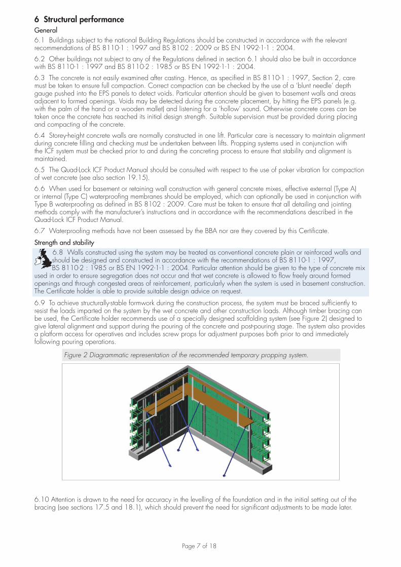
6.9 To achieve structurally-stable formwork during the construction process, the system must be braced sufficiently to resist the loads imparted on the system by the wet concrete and other construction loads. Although timber bracing can be used, the Certificate holder recommends use of a specially designed scaffolding system (see Figure 2) designed to give lateral alignment and support during the pouring of the concrete and post-pouring stage. The system also provides a platform access for operatives and includes screw props for adjustment purposes both prior to and immediately following pouring operations.
Figure 2 Diagrammatic representation of the recommended temporary propping system.
6.10 Attention is drawn to the need for accuracy in the levelling of the foundation and in the initial setting out of the bracing (see sections 17.5 and 18.1), which should prevent the need for significant adjustments to be made later.
Page 8 of 18
7 Thermal performance7.1 The thermal transmittance (U value) of an external wall construction will depend on the thickness and density of the polystyrene panels and the type of internal and external finishes used.
7.2 Calculations for specific constructions should be carried out in accordance with BS EN ISO 6946 : 2007, BS EN ISO 10211 : 2007 and BRE report 443 : 2006. The estimated thermal conductivity lambda (�90/90 value) of the EPS panels should be taken as 0.039 W·m–1·K–1.
7.3 Junctions with other elements should be designed to limit heat loss. The Certificate holder can provide relevant �(psi) values on request. Detailed guidance for junctions and on limiting heat loss by air infiltration can be found in:England and Wales — Approved Documents to Part L and, for new thermal elements to existing buildings, Accredited Construction Details (version 1.0) (for new-build, see also SAP 2009, Appendix K, and the iSBEM User Manual)Scotland — Accredited Construction Details (Scotland)(1)
Northern Ireland — Accredited Construction Details (version 1.0).(1) Flexible approaches on existing buildings are given in the Technical Handbooks
8 Airtightness8.1 Completed walls can achieve adequate resistance to heat loss by air infiltration provided there is effective sealing around junctions.
8.2 In England, Wales and Northern Ireland, completed buildings are subject to pre-completion testing for airtightness in accordance with the requirements of Approved Documents L1A and L2B, section 20A, Technical Booklet F1, sections 2.59 to 2.69 and Technical Booklet F2, sections 2.72 to 2.77 respectively.
8.3 In Scotland, completed dwellings are subject to testing air permeability in accordance with the requirements of Mandatory Standard 6.2 (clause 6.2.5). Alternatively, where a default design value of 15 m3·h–1·m–2, at a 50 Pa is stated in demonstrating compliance under Mandatory Standard 6.1, testing is not required.
(1) Technical Handbook (Domestic).(2) Technical Handbook (Non-Domestic)
9 Risk of condensationSurface condensation9.1 External walls will adequately limit the risk of surface condensation. Openings in walls and junctions with other elements, designed in accordance with the relevant guidance given in section 10, will also be acceptable.
Interstitial condensation9.2 Subject to the construction used and amount of vapour being produced, the risk of interstitial condensation will be minimal. Any vapour build-up will be low and will dissipate during the summer months. Therefore, a vapour check is not required. For the purposes of calculating condensation risk a nominal water vapour resistance factor (µ) of 60, in accordance with BS EN 12524 : 2000, may be taken for the EPS panels.
10 Sound insulation10.1 Separating walls with a concrete core density greater than 2000 kg·m–3 and a thickness of 150 mm, will achieve a minimum mass per unit area for the core of 300 kg·m–2. When used in conjunction with suitable framing, lining and flanking details, the wall can meet the requirements of a wall Type 3.
10.2 Separating walls in dwellings and rooms for residential purposes in England and Wales are subject to pre-completion testing in accordance with Section 1 of Approved Document E.
10.3 Internal walls and walls flanking separating walls in new dwellings and rooms for residential purposes will have a minimum mass per unit area, excluding finishes, of 120 kg·m–2.
11 WeathertightnessResistance to rain ingress is provided by the external finishes (not covered by this Certificate). Care should be taken to ensure that the design and construction comply with the relevant good practice described in the applicable codes and the Certificate holder’s installation procedures.
12 Damp-proofing and waterproofing12.1 The form elements will not transmit moisture by capillary action. The concrete wall formed with the system should be constructed using the specified concrete as recommended by the Certificate holder and the detailing should incorporate damp proof membranes where required (see also section 6.1 of this Certificate).
12.2 Use of the forms below ground to resist the effects of hydrostatic head or ground water ingress has not been assessed and is not covered by this Certificate. However, for general guidance when used below ground or at formation level, e.g. basements or retaining walls (see section 18.3), waterproofing membranes compatible with EPS
Page 9 of 18
must always be used. A suitable collector drain and backfilling medium should be provided to eliminate the build up of hydrostatic head behind the wall. The Certificate holder should be consulted for advice on suitable waterproofing materials and methods of waterproofing.
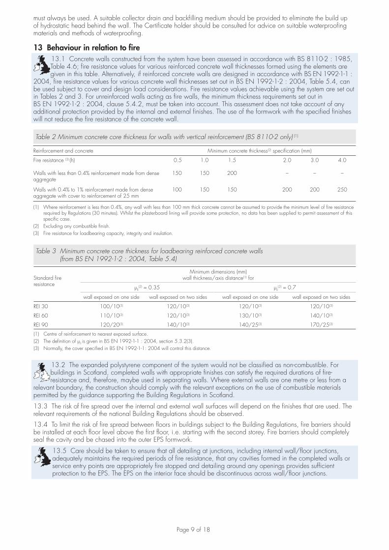
13 Behaviour in relation to fire13.1 Concrete walls constructed from the system have been assessed in accordance with BS 8110-2 : 1985, Table 4.6; fire resistance values for various reinforced concrete wall thicknesses formed using the elements are given in this table. Alternatively, if reinforced concrete walls are designed in accordance with BS EN 1992-1-1 :
2004, fire resistance values for various concrete wall thicknesses set out in BS EN 1992-1-2 : 2004, Table 5.4, can be used subject to cover and design load considerations. Fire resistance values achievable using the system are set out in Tables 2 and 3. For unreinforced walls acting as fire walls, the minimum thickness requirements set out in BS EN 1992-1-2 : 2004, clause 5.4.2, must be taken into account. This assessment does not take account of any additional protection provided by the internal and external finishes. The use of the formwork with the specified finishes will not reduce the fire resistance of the concrete wall.
Table 2 Minimum concrete core thickness for walls with vertical reinforcement (BS 8110-2 only) (1)
Reinforcement and concrete Minimum concrete thickness(2) specification (mm)
Fire resistance (3) (h) 0.5 1.0 1.5 2.0 3.0 4.0
Walls with less than 0.4% reinforcement made from dense aggregate
150 150 200 – – –
Walls with 0.4% to 1% reinforcement made from dense aggregate with cover to reinforcement of 25 mm
100 150 150 200 200 250
(1) Where reinforcement is less than 0.4%, any wall with less than 100 mm thick concrete cannot be assumed to provide the minimum level of fire resistance required by Regulations (30 minutes). Whilst the plasterboard lining will provide some protection, no data has been supplied to permit assessment of this specific case.
(2) Excluding any combustible finish.(3) Fire resistance for loadbearing capacity, integrity and insulation.
Table 3 Minimum concrete core thickness for loadbearing reinforced concrete walls(from BS EN 1992-1-2 : 2004, Table 5.4)
Standard fireresistance
Minimum dimensions (mm)wall thickness/axis distance(1) for
µfi(2) = 0.35 µfi
(2) = 0.7
wall exposed on one side wall exposed on two sides wall exposed on one side wall exposed on two sides
REI 30 100/10(3) 120/10(3) 120/10(3) 120/10(3)
REI 60 110/10(3) 120/10(3) 130/10(3) 140/10(3)
REI 90 120/20(3) 140/10(3) 140/25(3) 170/25(3)
(1) Centre of reinforcement to nearest exposed surface.(2) The definition of µfi is given in BS EN 1992-1-1 : 2004, section 5.3.2(3).(3) Normally, the cover specified in BS EN 1992-1-1: 2004 will control this distance.
13.2 The expanded polystyrene component of the system would not be classified as non-combustible. For buildings in Scotland, completed walls with appropriate finishes can satisfy the required durations of fire-resistance and, therefore, maybe used in separating walls. Where external walls are one metre or less from a
relevant boundary, the construction should comply with the relevant exceptions on the use of combustible materials permitted by the guidance supporting the Building Regulations in Scotland.
13.3 The risk of fire spread over the internal and external wall surfaces will depend on the finishes that are used. The relevant requirements of the national Building Regulations should be observed.
13.4 To limit the risk of fire spread between floors in buildings subject to the Building Regulations, fire barriers should be installed at each floor level above the first floor, i.e. starting with the second storey. Fire barriers should completely seal the cavity and be chased into the outer EPS formwork.
13.5 Care should be taken to ensure that all detailing at junctions, including internal wall/floor junctions, adequately maintains the required periods of fire resistance, that any cavities formed in the completed walls or service entry points are appropriately fire stopped and detailing around any openings provides sufficient protection to the EPS. The EPS on the interior face should be discontinuous across wall/floor junctions.
Page 10 of 18
14 Proximity of flues and appliancesWhen installing the product in close proximity to certain flue pipes and/or heat-producing appliances, the following provisions to the national Building Regulations are acceptable:England and Wales — Approved Document J3Scotland — Standards 3.18, clause 3.18.5(1)(2), and 3.19, clause 3.19.4(1)(2)
Northern Ireland — Technical Booklet L.(1) Technical Handbook (Domestic).(2) Technical Handbook (Non-Domestic).
15 Maintenance and repairMinor repairs to the system can be carried out prior to concrete pouring using expanding foam to reduce leakage of wet concrete and maintain the thermal integrity of the EPS.
16 Durability16.1 Concrete walls constructed with the system will have a service life of not less than 60 years provided they are designed in accordance with section 6. The EPS formwork will have a similar service life provided that it is protected from damage by the external and internal finishes of the wall construction (constituting a ‘mild’
exposure environment) and that these are adequately maintained.
16.2 The HDPE spacers are conventional building materials and will have durability compatible with that of the expanded polystyrene.
Installation
17 General17.1 The preparation, installation and support of the Quad-Lock Insulating Concrete Formwork (ICF) System panels and application of the specified finishes must be in accordance with the Quad-Lock ICF Product Manual.
17.2 All reinforcement should be accurately positioned to ensure that the minimum required concrete cover is provided. Starter or dowel bars, where required, must be to the engineer’s design. HDPE spacers should not be cut or modified when locating reinforcement.
17.3 Installation of the formwork should be carried out by trained operatives. The panels can be cut using conventional woodworking tools.
17.4 Durable and mechanically adequate fixings must be used for all structural elements or support brackets and must be post-drilled or cast into the concrete core. The EPS forming each of the system components must not be used as a structural medium although fixing/tie flanges as described in section 1.2 can be used. In specifying wall fixings carrying vertical loads, consideration should be given to the line of action of the load with respect to the face of the concrete wall and the effect on the strength of the fixing.
17.5 It is essential that effective bracing and propping of walls takes place during construction to ensure stability, level, straightness and plumb of walls. The Certificate holder recommends the use of a specially designed metal bracing system (not covered by this Certificate). This system, typically includes a vertical aluminium support channel, diagonal turnbuckle brace, a platform bracket and guardrail post assembly. Bracing and alignment systems should be between 1.5 m and 2 m horizontal centres but subject to verification by calculation depending on wall configuration.
17.6 Typically, for single storey lifts, the bracing and alignment systems are placed on one side of the formwork (usually the inside face) during construction. For other formwork constructions an engineer’s advice should be sought.
17.7 Consideration should be given at the design stage to the positioning of wall fixings, service pipes and joists, relative to the position of connecting assemblies. They can be incorporated by following the Certificate holder’s recommendations. Care must be taken not to damage the elements and thermal bridging effects must be considered.
18 Preparation18.1 The system requires that the foundation be level, smooth finished and within a tolerance of ±10 mm in any direction. Any out-of-tolerances must be made good prior to placement of formwork.
18.2 When stepped foundations are required, 305 mm steps should be provided to avoid cutting forms.
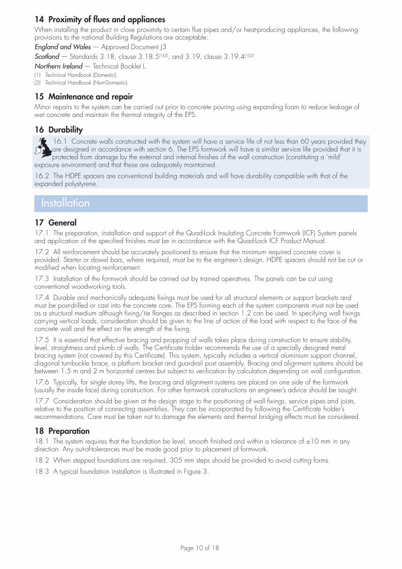
18.3 A typical foundation installation is illustrated in Figure 3.
Page 11 of 18
Figure 3 Typical detail — Wall on ground-floor slab
concrete screeddpm
insulation
hardcore concreteblinding
19 ProcedureLaying19.1 The inner and outer lines of the metal tracking are first fastened to the footing using masonry nails (or other suitable fixings) and lined level. Any gaps beneath the tracking are filled with low expansion polyurethane foam.
19.2 Construction commences by forming the corners and then working inwards towards the mid-point of each wall line. The long end (1220 mm) of the corner form should be used first, maintaining a running bond. With the first course it is also important to run the forms through door and deep window openings (these can be cut out later) so that interlocking of forms is maintained above each opening. The short end (616 mm) should be used next and alternated until each wall assembly is completed.
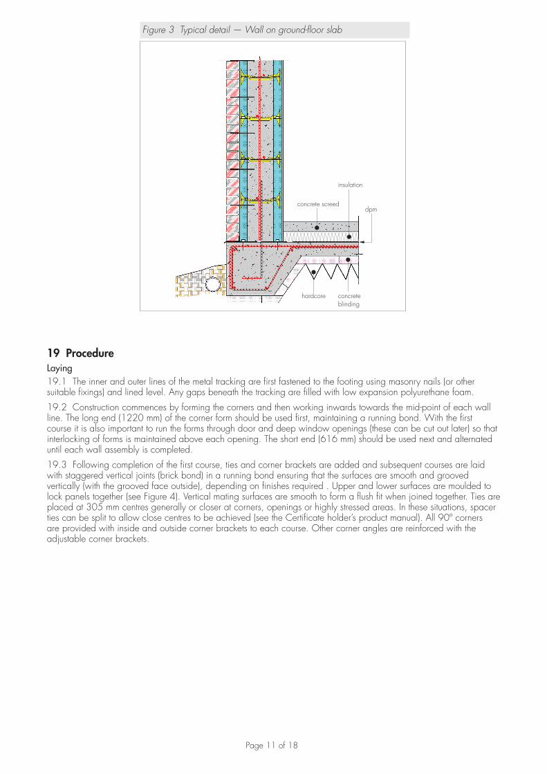
19.3 Following completion of the first course, ties and corner brackets are added and subsequent courses are laid with staggered vertical joints (brick bond) in a running bond ensuring that the surfaces are smooth and grooved vertically (with the grooved face outside), depending on finishes required . Upper and lower surfaces are moulded to lock panels together (see Figure 4). Vertical mating surfaces are smooth to form a flush fit when joined together. Ties are placed at 305 mm centres generally or closer at corners, openings or highly stressed areas. In these situations, spacer ties can be split to allow close centres to be achieved (see the Certificate holder’s product manual). All 90º corners are provided with inside and outside corner brackets to each course. Other corner angles are reinforced with the adjustable corner brackets.
Page 12 of 18
Figure 4 Basic assembly
tracking
EPS panel
tracking
foundation
wire top tie
spacer
19.4 Vertical joints formed at the mid-point of walls must be sealed with expanding foam on both sides. The foam should be allowed to set for at least 12 hours prior to pouring. Plywood plates or similar should be provided across mid-wall joints to provide additional strengthening during concrete pouring.
19.5 Internal wall formwork is jointed into external formwork by removal of a vertical slice (see Figure 5).
Figure 5 Horizontal internal-external separating wall joint
separating wall
vertical slice
EPS panel
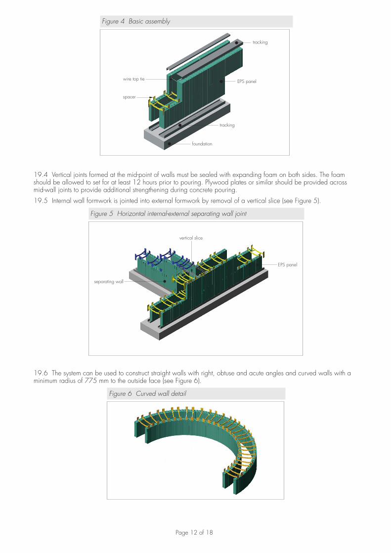
19.6 The system can be used to construct straight walls with right, obtuse and acute angles and curved walls with a minimum radius of 775 mm to the outside face (see Figure 6).
Figure 6 Curved wall detail
Page 13 of 18
Reinforcement19.7 The quantities of reinforcement placed within the system are dependent on the design and detail requirements. Horizontal reinforcement can be placed in different locations across the concrete fill void using the spacer slots. Vertical reinforcement can then be placed against the horizontal reinforcement and secured using standard fixing methods. Bar lapping lengths as per BS 8110-1 : 1997 should be adopted. The system requires that in plain walls, horizontal reinforcement be provided in top and bottom courses of every wall lift. Generally, high tensile reinforcement is used.
Restraint and propping19.8 Restraint is provided by securing the bottom course to the foundation using galvanized steel tracking, shot-fired or screwed into the foundation. The patent bracing system or other suitable propping system is then erected. Additional bracings are also recommended for basement walls. Bracings should be located so as not to interfere with door and window openings. All bracings are then anchored to the ground floor slab or firm ground with the aluminium channel or other support screw-fixed into the spacer flanges.
19.9 After erection of the bracing and propping, adjustments are made for plumb and level by use of screw jacks.
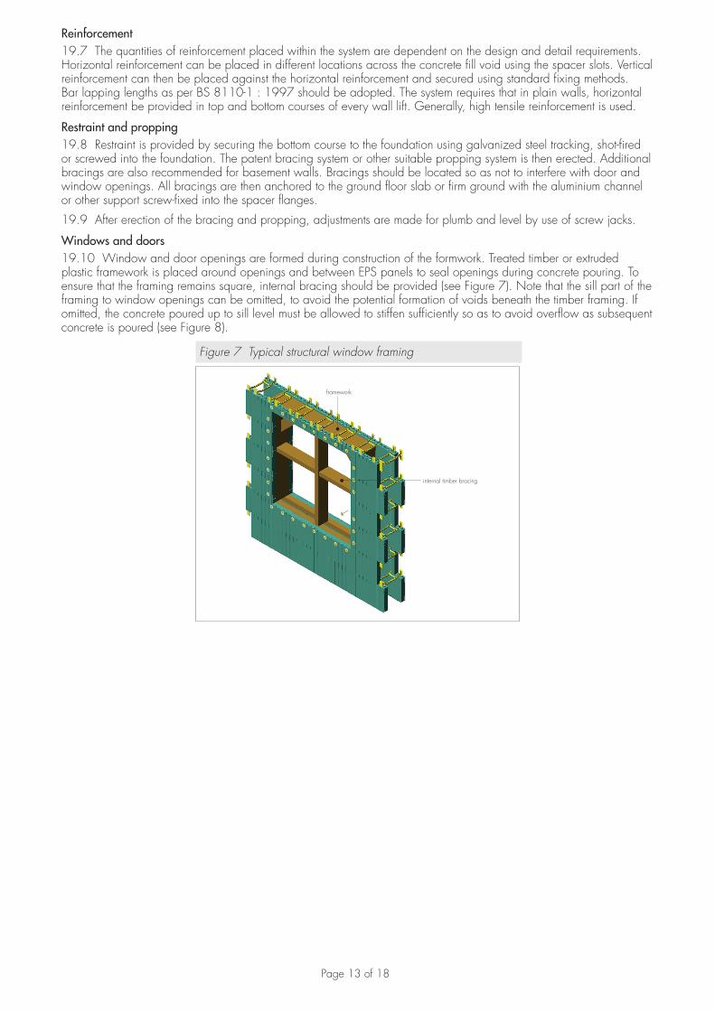
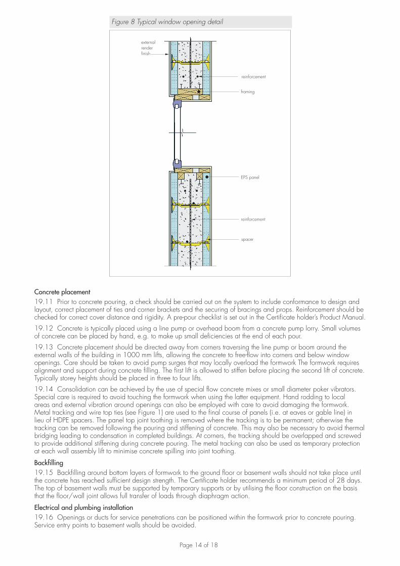
Windows and doors19.10 Window and door openings are formed during construction of the formwork. Treated timber or extruded plastic framework is placed around openings and between EPS panels to seal openings during concrete pouring. To ensure that the framing remains square, internal bracing should be provided (see Figure 7). Note that the sill part of the framing to window openings can be omitted, to avoid the potential formation of voids beneath the timber framing. If omitted, the concrete poured up to sill level must be allowed to stiffen sufficiently so as to avoid overflow as subsequent concrete is poured (see Figure 8).
Figure 7 Typical structural window framing
framework
internal timber bracing
Page 14 of 18
Figure 8 Typical window opening detail
framing
EPS panel
reinforcement
spacer
externalrenderfinish
reinforcement
Concrete placement19.11 Prior to concrete pouring, a check should be carried out on the system to include conformance to design and layout, correct placement of ties and corner brackets and the securing of bracings and props. Reinforcement should be checked for correct cover distance and rigidity. A pre-pour checklist is set out in the Certificate holder’s Product Manual.
19.12 Concrete is typically placed using a line pump or overhead boom from a concrete pump lorry. Small volumes of concrete can be placed by hand, e.g. to make up small deficiencies at the end of each pour.
19.13 Concrete placement should be directed away from corners traversing the line pump or boom around the external walls of the building in 1000 mm lifts, allowing the concrete to free-flow into corners and below window openings. Care should be taken to avoid pump surges that may locally overload the formwork The formwork requires alignment and support during concrete filling. The first lift is allowed to stiffen before placing the second lift of concrete. Typically storey heights should be placed in three to four lifts.
19.14 Consolidation can be achieved by the use of special flow concrete mixes or small diameter poker vibrators. Special care is required to avoid touching the formwork when using the latter equipment. Hand rodding to local areas and external vibration around openings can also be employed with care to avoid damaging the formwork. Metal tracking and wire top ties (see Figure 1) are used to the final course of panels (i.e. at eaves or gable line) in lieu of HDPE spacers. The panel top joint toothing is removed where the tracking is to be permanent; otherwise the tracking can be removed following the pouring and stiffening of concrete. This may also be necessary to avoid thermal bridging leading to condensation in completed buildings. At corners, the tracking should be overlapped and screwed to provide additional stiffening during concrete pouring. The metal tracking can also be used as temporary protection at each wall assembly lift to minimise concrete spilling into joint toothing.
Backfilling19.15 Backfilling around bottom layers of formwork to the ground floor or basement walls should not take place until the concrete has reached sufficient design strength. The Certificate holder recommends a minimum period of 28 days. The top of basement walls must be supported by temporary supports or by utilising the floor construction on the basis that the floor/wall joint allows full transfer of loads through diaphragm action.
Electrical and plumbing installation19.16 Openings or ducts for service penetrations can be positioned within the formwork prior to concrete pouring. Service entry points to basement walls should be avoided.
Page 15 of 18
19.17 Electrical and plumbing services may be located within the concrete core, subject to structural design consideration. Only if unavoidable, should electrical wiring conduits and small diameter pipework be installed in chases routed into the EPS panels. Bare wiring must not be in contact with the EPS. Any services introduced should conform to Building Regulation and Health and Safety requirements. Further details on fixing methods can be obtained from the Certificate holder.
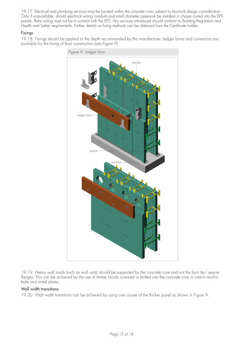
Fixings19.18 Fixings should be applied to the depth recommended by the manufacturer. Ledger forms and connectors are available for the fixing of floor construction (see Figure 9).
Figure 9 Ledger form
bracket
ledger form
spacer
tracking
19.19 Heavy wall loads (such as wall units) should be supported by the concrete core and not the form tie/ spacer flanges. This can be achieved by the use of timber blocks screwed or bolted into the concrete core or cast-in anchor bolts and metal plates.
Wall width transitions19.20 Wall width transitions can be achieved by using one course of the thicker panel as shown in Figure 9.
Page 16 of 18
Intermediate floors and roof19.21 A range of floor and roof systems can be accommodated with the system. Further details can be obtained from the Certificate holder.
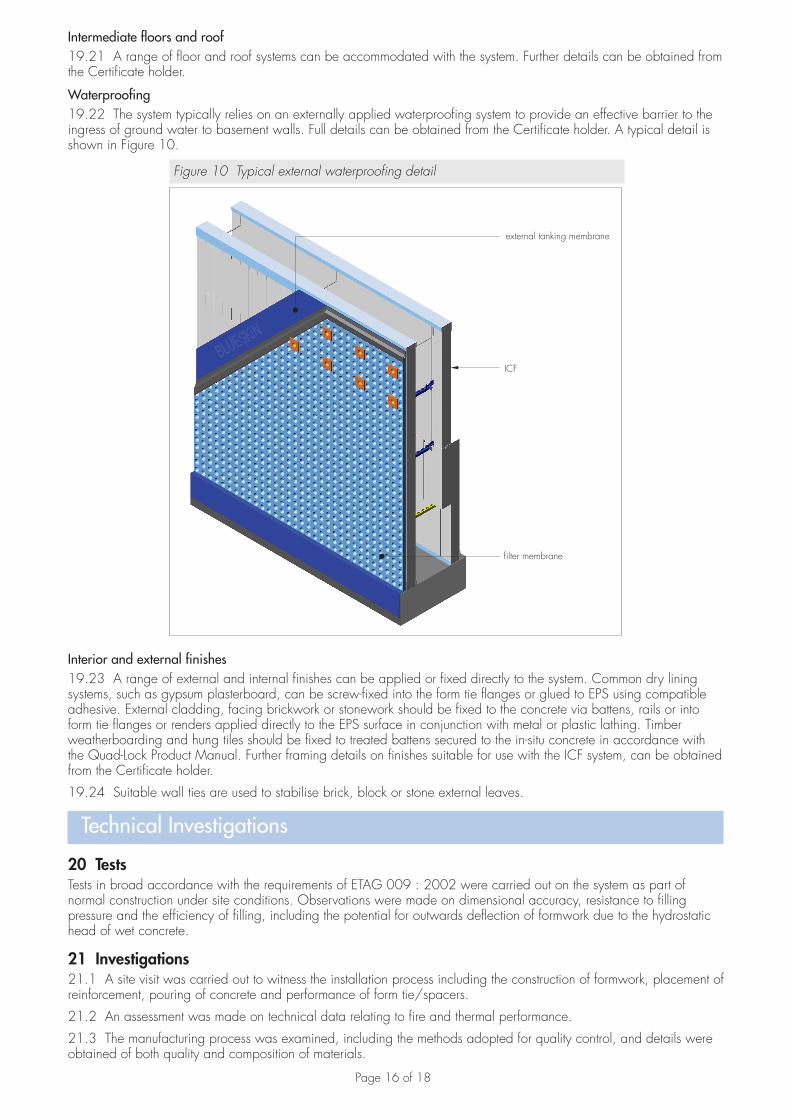
Waterproofing19.22 The system typically relies on an externally applied waterproofing system to provide an effective barrier to the ingress of ground water to basement walls. Full details can be obtained from the Certificate holder. A typical detail is shown in Figure 10.
Figure 10 Typical external waterproofing detail
external tanking membrane
ICF
filter membrane
Interior and external finishes19.23 A range of external and internal finishes can be applied or fixed directly to the system. Common dry lining systems, such as gypsum plasterboard, can be screw-fixed into the form tie flanges or glued to EPS using compatible adhesive. External cladding, facing brickwork or stonework should be fixed to the concrete via battens, rails or into form tie flanges or renders applied directly to the EPS surface in conjunction with metal or plastic lathing. Timber weatherboarding and hung tiles should be fixed to treated battens secured to the in-situ concrete in accordance with the Quad-Lock Product Manual. Further framing details on finishes suitable for use with the ICF system, can be obtained from the Certificate holder.
19.24 Suitable wall ties are used to stabilise brick, block or stone external leaves.
Technical Investigations
20 TestsTests in broad accordance with the requirements of ETAG 009 : 2002 were carried out on the system as part of normal construction under site conditions. Observations were made on dimensional accuracy, resistance to filling pressure and the efficiency of filling, including the potential for outwards deflection of formwork due to the hydrostatic head of wet concrete.
21 Investigations21.1 A site visit was carried out to witness the installation process including the construction of formwork, placement of reinforcement, pouring of concrete and performance of form tie/spacers.
21.2 An assessment was made on technical data relating to fire and thermal performance.
21.3 The manufacturing process was examined, including the methods adopted for quality control, and details were obtained of both quality and composition of materials.
Page 17 of 18
BibliographyBRE report 443 : 2006 Conventions for U-value calculationsBS 4449 : 2005+A2 : 2009 Steel for the reinforcement of concrete — Weldable reinforcing steel — Bar coil and decoiled product — Specification BBS 8102 : 2009 Code of practice for protection of below ground structures against water from the groundBS 8110-1 : 1997 Structural use of concrete — Code of practice for design and constructionBS 8110-2 : 1985 Structural use of concrete — Code of practice for special circumstancesBS 8212 : 1995 Code of practice for dry lining and partitioning using gypsum plasterboardBS 8298-1 : 2010 Code of practice for the design and installation of natural stone cladding and lining. GeneralBS EN 206-1 : 2000 Concrete — Specification, performance, production and conformityBS EN 845-1 : 2003 Specification for ancillary components for masonry — Ties, tension straps, hangers and bracketsBS EN 934-2 : 2009 + A1 : 2012 Admixtures for concrete, mortar and grout — Concrete admixtures — Definitions, requirements, conformity, marking and labellingBS EN 1992-1-1 : 2004 Eurocode 2 : Design of concrete structures. General rules and rules for buildingsBS EN 1992-1-2 : 2004 Eurocode 2 : Design of concrete structures — General rules — Structural fire designBS EN 1996-1-1 : 2005 Eurocode 6 — Design of masonry structures — General rules for reinforced and unreinforced masonry structuresBS EN 1996-1-2 : 2005 Eurocode 6 — Design of masonry structures — General rules — Structural fire designBS EN 1996-2 : 2006 UK National Annex to Eurocode 6 — Design of masonry structures — Design considerations, selection of materials and execution of masonryBS EN 1996-3 : 2006 UK National Annex to Eurocode 6 — Design of masonry structures. Simplified calculation methods for unreinforced masonry structuresBS EN 12524 : 2000 Building materials and products. Hygrothermal properties. Tabulated design valuesBS EN 13163 : 2012 Thermal insulation products for buildings. Factory made expanded polystyrene (EPS) products. SpecificationBS EN 13914-1:2005 Design, preparation and application of external rendering and internal plastering. External renderingBS EN ISO 6946 : 2007 Building components and building elements — Thermal resistance and thermal transmittance — Calculation methodBS EN ISO 10211 : 2007 Thermal bridges in building construction. Heat flows and surface temperatures. Detailed calculationsETAG 009 : 2002 Guideline for European Technical Approval of non-loadbearing permanent shuttering kits/systems based on hollow blocks or panels of insulating materials and sometimes concretePD 6697 : 2010 Recommendations for the design of masonry structures to BS EN 1996-1-1 and BS EN 1996-2
Page 18 of 18
Conditions of Certification
22 Conditions22.1 This Certificate:• relates only to the product/system that is named and described on the front page• is issued only to the company, firm, organisation or person named on the front page — no other company, firm,
organisation or person may hold or claim that this Certificate has been issued to them• is valid only within the UK• has to be read, considered and used as a whole document — it may be misleading and will be incomplete to be
selective• is copyright of the BBA• is subject to English Law.
22.2 Publications, documents, specifications, legislation, regulations, standards and the like referenced in this Certificate are those that were current and/or deemed relevant by the BBA at the date of issue or reissue of this Certificate.
22.3 This Certificate will remain valid for an unlimited period provided that the product/system and its manufacture and/or fabrication, including all related and relevant parts and processes thereof:• are maintained at or above the levels which have been assessed and found to be satisfactory by the BBA• continue to be checked as and when deemed appropriate by the BBA under arrangements that it will determine• are reviewed by the BBA as and when it considers appropriate.
22.4 The BBA has used due skill, care and diligence in preparing this Certificate, but no warranty is provided.
22.5 In issuing this Certificate, the BBA is not responsible and is excluded from any liability to any company, firm, organisation or person, for any matters arising directly or indirectly from:• the presence or absence of any patent, intellectual property or similar rights subsisting in the product/system or any
other product/system• the right of the Certificate holder to manufacture, supply, install, maintain or market the product/system• actual installations of the product/system, including their nature, design, methods, performance, workmanship and
maintenance• any works and constructions in which the product/system is installed, including their nature, design, methods,
performance, workmanship and maintenance• any loss or damage, including personal injury, howsoever caused by the product/system, including its manufacture,
supply, installation, use, maintenance and removal• any claims by the manufacturer relating to CE marking.
22.6 Any information relating to the manufacture, supply, installation, use, maintenance and removal of this product/system which is contained or referred to in this Certificate is the minimum required to be met when the product/system is manufactured, supplied, installed, used, maintained and removed. It does not purport in any way to restate the requirements of the Health and Safety at Work etc. Act 1974, or of any other statutory, common law or other duty which may exist at the date of issue or reissue of this Certificate; nor is conformity with such information to be taken as satisfying the requirements of the 1974 Act or of any statutory, common law or other duty of care.
British Board of Agrément tel: 01923 665300Bucknalls Lane fax: 01923 665301Watford e-mail: [email protected] WD25 9BA website: www.bbacerts.co.uk©2013