alberta distributed generation - howell-mayhew … dg guide final 2002 july 16.pdf · alberta...
TRANSCRIPT
Final Version July 16, 2002
Alberta Distributed GenerationInterconnection Guide
The Alberta Distributed Generation Interconnection Guide provides guidelines forconnecting a generation facility to the Alberta Interconnected Electric System(AIES) via a Wires Owner’s distribution system, and assists in determining thetechnical and operating requirements of the facility.
The Guide was developed by the Alberta Distributed Generation Technical andPolicy Committee without regard to whether its adoption may involve patents onarticles, materials or processes. Such adoption does not assume any liability toany patent owner, nor does it assume any obligation whatsoever to partiesadopting this Guide.
While every precaution has been taken in preparing the Guide, it may containinadvertent inaccuracies or inconsistencies. The authors assume no liability forerrors or omissions, or damages resulting from the use of or reliance upon theinformation contained herein.

Alberta Distributed GenerationInterconnection Guide
Page 2 of 67Final Version July 16, 2002
In this document…
Part 1 – General Interconnection Information ............................. 3Part 2 – Guide for Generator Interconnection............................11
Appendices ............................................................................45
Alberta Distributed GenerationInterconnection Guide
Page 3 of 67Final Version July 16, 2002
Part 1 – General Interconnection Information
In this part…1.0 Introduction ...................................................................... 42.0 Terms and Definitions ....................................................... 53.0 Responsibilities ................................................................ 74.0 Metering Requirements..................................................... 95.0 Operating Requirements..................................................10

Part 1:General Interconnection Information
Page 4 of 67Final Version July 16, 2002
1.0 Introduction
1.1 Intent
The intent of the Alberta Distributed Generation Interconnection Guide(hereinafter referred to as “the Guide” or “this Guide”) is to:
1. Inform and provide guidelines for anyone wishing to connect ageneration facility to the AIES via a Wires Owner’s distributionsystem; and
2. Assist operators, technical staff, consultants and contractors indetermining the technical and operating requirements of the facility.
This Guide does not:
3. Establish commercial or cost-sharing agreements. Each WiresOwner will have approved tariffs, including terms and conditions andelectric service agreements for Distributed Generation (DG) andnormal or standby consumption at the site. The DG Owner isencouraged to review its commercial obligations at the time ofapplication.
4. Provide guidelines for connecting to the system at voltages above25kV. For information on connecting directly to the transmissionsystem, see Technical Requirements for Connecting to the AlbertaInterconnected Electric System Transmission System at theTransmission Administrator's web site at www.eal.ab.ca.
For a complete description of the electric power industry in Alberta underthe Electric Utilities Act, please refer to the Alberta Energy website,www.energy.gov.ab.ca/electric.
1.2 Guiding Principles
This Guide was developed in accordance with the following principles:
1. The interconnection process must provide competitive, fair andequitable access for all DG Owners.
2. The interconnection must not create a safety hazard to othercustomers, the public or operating personnel.
3. The interconnection must not compromise the reliability or restrict theoperation of the electric system.
4. The interconnection must not degrade power quality belowacceptable levels.
Part 1:General Interconnection Information
Page 5 of 67Final Version July 16, 2002
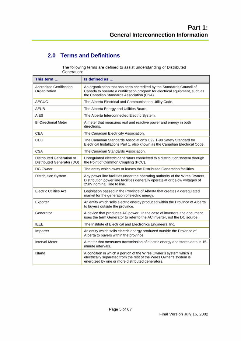
2.0 Terms and Definitions
The following terms are defined to assist understanding of DistributedGeneration:
This term … Is defined as …
Accredited CertificationOrganization
An organization that has been accredited by the Standards Council ofCanada to operate a certification program for electrical equipment, such asthe Canadian Standards Association (CSA).
AECUC The Alberta Electrical and Communication Utility Code.
AEUB The Alberta Energy and Utilities Board.
AIES The Alberta Interconnected Electric System.
Bi-Directional Meter A meter that measures real and reactive power and energy in bothdirections.
CEA The Canadian Electricity Association.
CEC The Canadian Standards Association's C22.1-98 Safety Standard forElectrical Installations Part 1, also known as the Canadian Electrical Code.
CSA The Canadian Standards Association.
Distributed Generation orDistributed Generator (DG)
Unregulated electric generators connected to a distribution system throughthe Point of Common Coupling (PCC).
DG Owner The entity which owns or leases the Distributed Generation facilities.
Distribution System Any power line facilities under the operating authority of the Wires Owners.Distribution power line facilities generally operate at or below voltages of25kV nominal, line to line.
Electric Utilities Act Legislation passed in the Province of Alberta that creates a deregulatedmarket for the generation of electric energy.
Exporter An entity which sells electric energy produced within the Province of Albertato buyers outside the province.
Generator A device that produces AC power. In the case of inverters, the documentuses the term Generator to refer to the AC inverter, not the DC source.
IEEE The Institute of Electrical and Electronics Engineers, Inc.
Importer An entity which sells electric energy produced outside the Province ofAlberta to buyers within the province.
Interval Meter A meter that measures transmission of electric energy and stores data in 15-minute intervals.
Island A condition in which a portion of the Wires Owner’s system which iselectrically separated from the rest of the Wires Owner’s system isenergized by one or more distributed generators.
Part 1:General Interconnection Information
Page 6 of 67Final Version July 16, 2002
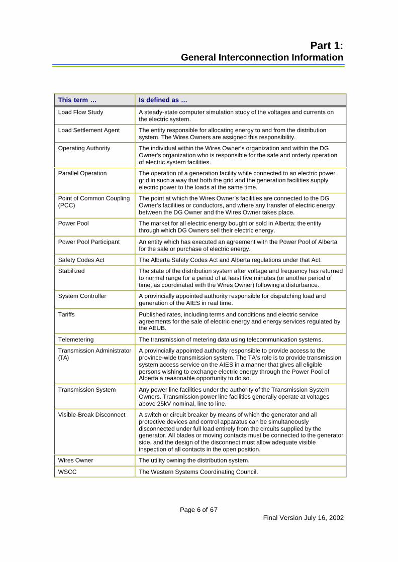
This term … Is defined as …
Load Flow Study A steady-state computer simulation study of the voltages and currents onthe electric system.
Load Settlement Agent The entity responsible for allocating energy to and from the distributionsystem. The Wires Owners are assigned this responsibility.
Operating Authority The individual within the Wires Owner’s organization and within the DGOwner's organization who is responsible for the safe and orderly operationof electric system facilities.
Parallel Operation The operation of a generation facility while connected to an electric powergrid in such a way that both the grid and the generation facilities supplyelectric power to the loads at the same time.
Point of Common Coupling(PCC)
The point at which the Wires Owner’s facilities are connected to the DGOwner’s facilities or conductors, and where any transfer of electric energybetween the DG Owner and the Wires Owner takes place.
Power Pool The market for all electric energy bought or sold in Alberta; the entitythrough which DG Owners sell their electric energy.
Power Pool Participant An entity which has executed an agreement with the Power Pool of Albertafor the sale or purchase of electric energy.
Safety Codes Act The Alberta Safety Codes Act and Alberta regulations under that Act.
Stabilized The state of the distribution system after voltage and frequency has returnedto normal range for a period of at least five minutes (or another period oftime, as coordinated with the Wires Owner) following a disturbance.
System Controller A provincially appointed authority responsible for dispatching load andgeneration of the AIES in real time.
Tariffs Published rates, including terms and conditions and electric serviceagreements for the sale of electric energy and energy services regulated bythe AEUB.
Telemetering The transmission of metering data using telecommunication systems.
Transmission Administrator(TA)
A provincially appointed authority responsible to provide access to theprovince-wide transmission system. The TA’s role is to provide transmissionsystem access service on the AIES in a manner that gives all eligiblepersons wishing to exchange electric energy through the Power Pool ofAlberta a reasonable opportunity to do so.
Transmission System Any power line facilities under the authority of the Transmission SystemOwners. Transmission power line facilities generally operate at voltagesabove 25kV nominal, line to line.
Visible-Break Disconnect A switch or circuit breaker by means of which the generator and allprotective devices and control apparatus can be simultaneouslydisconnected under full load entirely from the circuits supplied by thegenerator. All blades or moving contacts must be connected to the generatorside, and the design of the disconnect must allow adequate visibleinspection of all contacts in the open position.
Wires Owner The utility owning the distribution system.
WSCC The Western Systems Coordinating Council.
Part 1:General Interconnection Information
Page 7 of 67Final Version July 16, 2002
3.0 Responsibilities
Refer to Appendix A for a block diagram of the approval process forconnecting a generation facility to a Wires Owner’s distribution system.
3.1 DG Owner Responsibilities
The DG Owner is responsible to:
Ø Become a Power Pool Participant and comply with any Power Poolrequirements (unless all energy produced at the site is to beconsumed at the site);
Ø Provide technical information to the Wires Owner and to theTransmission Administrator, as specified in Appendix B;
Ø Design, install, operate and maintain the interconnection facility:• Ensure all necessary designs and drawings are signed and
stamped by a licensed, professional engineer;• Have equipment certified by an accredited certification
organization; and• Verify that the installation conforms to the current edition of Part I
of the CEC;Ø Pay the costs of interconnection, in accordance with the commercial
terms established by the Wires Owner;Ø Obtain all required permits and licenses:
• Ensure that the local inspection and Safety Codes Actenforcement authorities accept the installation, or that theinstallation falls under the jurisdiction of an accreditedcorporation under the Safety Codes Act;
• Before commissioning and commencing parallel operation,obtain the approval of the Wires Owner and establish a JointOperating Agreement with the Wires Owner, similar to thegeneric Joint Operating Agreement provided in Appendix C,covering the technical and operating requirements;
• Obtain AEUB approval and order to connect, and provide theAEUB approval and order numbers to the Wires Owner (AEUBapproval requires a Joint Operating Agreement to be in placebetween the DG Owner and the Wires Owner);
Ø Obtain written approval from the Wires Owner before commencingparallel operation and before making any modification to thegeneration facility;
Ø Ensure metering requirements are met (see section 4.0); andØ Negotiate the timing and any testing requirements for the
commissioning process with the Wires Owner, and if needed, withthe Transmission Administrator and/or the System Controller.
Part 1:General Interconnection Information
Page 8 of 67Final Version July 16, 2002
3.2 Wires Owner Responsibilities
The Wires Owner is responsible to:
Ø Carry out load flow studies within a reasonable period;Ø Prepare a Joint Operating Agreement with the DG Owner, similar to
the generic Joint Operating Agreement provided in Appendix C;Ø Prepare a commercial agreement to address cost recovery;Ø Inform the DG Owner of the Wires Owner’s current standards and
practices, as they relate to the interconnection;Ø Ensure metering requirements are met (see section 4.0); andØ Provide the DG Owner with the information specified in Appendix D.
Part 1:General Interconnection Information
Page 9 of 67Final Version July 16, 2002
4.0 Metering Requirements
Both the DG Owner and the Wires Owner must meet requirementsrelated to metering.
The DG Owner is required to:
Ø Install an electric meter to measure active energy and reactiveenergy flowing out of the generation facility to the distribution system.The Wires Owner retains the right to obtain this data for internal use.
The Wires Owner is required to:Ø Install an electric meter to measure power, active energy and
reactive energy flowing from the distribution system into thegeneration facility. The DG Owner retains the right to obtain thismetering data for internal use.
As agreeable between the parties, one physical bi-directional meter maybe used to fulfill the requirements of both parties.
Metering service companies are available in Alberta. These includedistribution Wires Owners, as well as independent metering companies.Measurement Canada is responsible for testing and certification ofmeters.

Part 1:General Interconnection Information
Page 10 of 67Final Version July 16, 2002
5.0 Operating Requirements
5.1 Operating Authority
The Wires Owner and the DG Owner must each identify, by name or byjob title, the individual within their organizations who is their “OperatingAuthority.” The Operating Authority is responsible to establish operatingprocedures and standards within each organization.
The Operating Authority negotiates and signs the Joint OperatingAgreement described in section 5.3. This individual also ensures that theOperator in Charge (see below) is competent to operate their respectivesystem and aware of the provisions of any other operating agreementsand any regulations that may apply.
5.2 Operator in Charge
The Wires Owner and the DG Owner must each identify the individual,by name or by job title, who is the “Operator in Charge” of their facilitiesand operates their portion of the interconnection facility. This individualmust be familiar with the Joint Operating Agreement, and also aware ofthe provisions of any other operating agreements and any regulationsthat may apply. The Operating Authority and the Operator in Charge maybe the same person.
5.3 Joint Operating Agreement
A Joint Operating Agreement must be established between the WiresOwner and the DG Owner to provide for the safe and orderly operation ofthe interconnection facility. The Agreement must include, but is notnecessarily limited to, the following:Ø A high-level technical description of the DG Owner’s generation facility,
equipment and protection.Ø A high-level technical description of the Wires Owner’s distribution system
facilities and protection.Ø A description of how the generation facility will operate (e.g., parallel or
islanded).Ø The DG Owner’s intent in operating the generation facility (e.g., sales,
demand reduction).Ø The name, title and telephone number(s) of the Operating Authority and the
Operator in Charge for each party to the Agreement.Ø Provision for the Wires Owner to disconnect the generation facility if it fails to
meet technical and/or power quality requirements, or if the operation of thegeneration facility is or may become dangerous to life or property.
Ø Reference to safety procedures for joint work.Ø Identification of responsibility for maintaining current operating information.Ø Isolation procedures for work on the facilities.Ø Notification requirements, if required before synchronization.Ø Any control setting parameters that could affect the interconnection (e.g.,
voltage and frequency).Ø The approval of both the Wires Owner and the DG Owner.
A generic Joint Operating Agreement is provided in Appendix C.

Alberta Distributed GenerationInterconnection Guide
Page 11 of 67 Final Version July 16, 2002
Part 2 – Guide for Generator Interconnection
In this part…1.0 Purpose..........................................................................122.0 Limitations ......................................................................133.0 General Interconnection and Protection Requirements.......144.0 Construction....................................................................305.0 Metering .........................................................................316.0 Inspection .......................................................................337.0 Testing............................................................................348.0 Data Requirements..........................................................389.0 Marking And Tagging.......................................................3910.0 Maintenance ...................................................................40Tables ....................................................................................41

Part 2:Guide for Generator Interconnection
Page 12 of 67Final Version July 16, 2002
1.0 Purpose
The second part of this Guide establishes the criteria and technicalrequirements for interconnecting generation facilities with distributionsystems (25kV or lower). Specifically, it addresses the performance,operation, testing, safety considerations and maintenance requirementsof the interconnection.
These requirements cover a broad spectrum of interests. Interconnectinggeneration facilities to a distribution system may change the system andits response. Attaining a technically sound and robust interconnectionmandates diligence on the part of everyone involved, includingdesigners, manufacturers, users, owners and operators of both thegeneration facilities and the distribution systems. All of the above-mentioned groups need to reach a cooperative understanding of andmeet the requirements established herein.
This Guide was developed with reference to international standards,such as the IEEE Standard P1547 DRAFT Standard for DistributedResources Interconnected with Distribution Systems. It is subject toregular review and revision, as necessary to conform to evolving Albertaand international standards, such as those developed by the IEEE.
This Guide is not a design handbook. Anyone consideringdevelopment of a generation facility intended for interconnection to adistribution system should engage the services of individuals qualified toprovide design and consulting services for electrical interconnectionfacilities.
Part 2:Guide for Generator Interconnection
Page 13 of 67Final Version July 16, 2002
2.0 Limitations
The criteria and requirements established by this Guide are applicable toall DG technologies and to the primary and secondary voltages of thedistribution systems. Installation of DG facilities on the radial primary andsecondary distribution systems is the main focus of this version, althoughnetwork distribution systems are considered. For this version, therequirements must be met at the Point of Common Coupling (PCC),although the protective devices may not necessarily be located at thatpoint.
This Guide establishes the minimum requirements for theinterconnection. Additional requirements may need to be met by both theDG Owner and the Wires Owner to ensure that the final interconnectiondesign meets all local and national standards and codes, and that thedesign is safe for the intended application. The Guide does not addressany liability provisions agreed to elsewhere by both parties in acommercial agreement, or through tariff terms and conditions.

Part 2:Guide for Generator Interconnection
Page 14 of 67Final Version July 16, 2002
3.0 General Interconnection and Protection Requirements
The DG Owner’s generation and interconnection facilities must meet allapplicable national, provincial and local construction and safety codes.See Appendix E for a complete listing of commonly used codes andstandards.
Anyone may operate a 60 Hertz, three-phase or single-phase generationfacility, in parallel with the Wires Owner’s distribution system and inaccordance with the Joint Operating Agreement established with theWires Owner, provided the requirements of this Guide are met orexceeded.
The DG Owner is required to install, operate and maintain in good orderand repair at all times, in conformity with good electrical practice, theequipment required by this Guide for the safe parallel operation with theWires Owner’s distribution system.
The following three sections, 3.1, 3.2, and 3.3, define the technicalrequirements for the distribution system, the generation facility and theinterconnection facility respectively. These requirements promote safeoperation and minimize the impact of the interconnection to the WiresOwner’s distribution system and its other customers.
This Guide is not intended to provide protection for the DG Owner’sgeneration facility. It is the responsibility of the DG Owner to protect theirfacility in such a manner that distribution system outages, short circuitsor other disturbances, including excessive zero sequence currents andferroresonant over-voltages, do not cause damage. The DG Owner’sprotective equipment must also prevent excessive or unnecessarytripping that could affect the reliability of the distribution system or powerquality to other customers.
Refer to Tables 1, 2 and 3 and Appendices F and G for interconnectionprotective function requirements.
3.1 Distribution System
3.1.1 System Frequency
The AIES operates at 60 Hertz (Hz) Alternating Current (AC).Frequency variations are typically 59.7 Hz to 60.2 Hz for smallcontingencies that cause modest disturbances, but do notnoticeably disrupt the AIES or its connection to the WesternSystem.
Variations of 58 Hz to 61 Hz or greater can occur for largercontingencies, for example if a portion of the AIES is required tobe islanded.
Part 2:Guide for Generator Interconnection
Page 15 of 67Final Version July 16, 2002
3.1.2 Voltage Regulation
CSA Standard CAN3 C235 83: Preferred Voltage Levels for ACSystems 0 to 50,000V provides general guidance as toappropriate performance.
3.1.3 Power Quality
All interconnected equipment must comply with the WiresOwner’s standards for power quality.
The following industry standards may provide guidance as toappropriate performance:
Ø Voltage Flicker - IEEE Std. 519-1992 IEEE RecommendedPractices and Requirements for Harmonic Control inElectrical Power Systems.
Ø Harmonics - Wires Owner’s Guide for the Connection ofNon-Linear Load.
3.1.4 Voltage Unbalance
Distribution systems are typically three-phase systemsincorporating single-phase distribution taps. The voltageunbalance on a distribution system under normal operatingconditions may reach three per cent, due to the unbalancedloading and single-phase regulation. Voltage unbalance will becalculated using the following formula, as derived from NEMAMG1-1993 14.35:
Unbalance (%) = 100 x (deviation from average) / (average).
3.1.5 Fault Levels
Fault levels and maximum allowable fault levels vary significantlythrough a distribution system and must be considered in thedesign of the interconnection. Fault levels and X/R ratios mustbe evaluated for the equipment selected.
3.1.6 System Grounding
Distribution systems are typically operated as effectively (solidly)grounded and Wye-connected at the source substation bus.Other configurations are occasionally found.
Distribution system grounding must conform to the AECUC(formerly the Alberta Electrical and Communication UtilitySystem Regulation 44/1976, or future amendments).
3.1.7 Fault and Line Clearing
To maintain the reliability of the distribution system, the WiresOwner uses automatic re-closing. The DG Owner must take this
Part 2:Guide for Generator Interconnection
Page 16 of 67Final Version July 16, 2002
into consideration when designing generator protection schemesto ensure the generator is disconnected from the Wires Owner’ssystem prior to the automatic re-close of breakers. The DGOwner may reconnect when the Wires Owner’s system isstabilized.
To enhance reliability and safety, with the Wires Owner’sapproval the DG Owner may employ a modified relay schemewith tripping or blocking using communications equipmentbetween the DG facility and distribution system facilities.
3.2 Generation Facility
3.2.1 Mitigation of Adverse Effects
Interconnecting distributed generation can adversely affect theelectric service to existing or future customers. The DG Ownermust work with the Wires Owner to mitigate any adverse affects.
If a generation facility is affecting customers adversely, the WiresOwner may disconnect it until such time as the concern hasbeen mitigated. The DG Owner is responsible for any costsincurred as a result.
3.2.2 Synchronism
Any generation facility that can create an AC voltage whileseparate from the electric system must have synchronizationfacilities to allow its connection to the electric system.
Inverter-type, voltage-following equipment that cannot generatean AC voltage while separate from the electric system does notrequire synchronization facilities; nor do induction generatorsthat act as motors during start-up, drawing power from theelectric system before generating their own power.
The DG Owner is responsible to synchronize and maintainsynchronization to the Wires Owner’s system. The WiresOwner’s system cannot synchronize to the generation facility. Aproposed synchronizing scheme must be submitted and outlinedin the Joint Operating Agreement and attachments.
Distribution and transmission systems typically allow forautomatic re-closing of electrical circuits after a variable timedelay. The DG Owner is responsible for protecting their ownfacility from the impacts of such re-closing.
Generators can automatically restart following automatic re-closing of distribution system equipment, if agreed to by theWires Owner. Generators that automatically restart must have atime delay on restart, adjustable up to 60 minutes or as agreedto by the Wires Owner. The Wires Owner will coordinate thesettings of generator restart time delays so that generators onany feeder restart in staggered order.
3.2.3 Voltage Regulation and Power Factor

Part 2:Guide for Generator Interconnection
Page 17 of 67Final Version July 16, 2002
The DG Owner is responsible to ensure that the voltage levels atthe PCC are maintained within the guidelines prescribed by theWires Owner and/or are at least equal to the voltage levels at allfeeder load conditions, prior to the interconnection.
Synchronous generators connected to the distribution systemmust be equipped with excitation controllers capable ofcontrolling voltage. The generator-bus voltage setpoint must bestable at and adjustable to any value between 95 per cent and105 per cent so that the Wires Owner can maintain CSA voltagelimits on the distribution system.
Induction generators do not have voltage or reactive powercontrol and consume reactive power (VAR). Therefore, thegenerator must provide reactive compensation to correct thepower factor to ± 0.90 at the PCC, unless other terms arenegotiated with the Wires Owner.
Inverter-type generating equipment can control the power factorover a wide range, typically ± 0.75. An inverter-type generatorconnected to the distribution system must be capable ofadjusting the power factor in the range of +/- 0.9. The DG Ownermay operate outside that range by agreement with the WiresOwner.
The Wires Owner will define voltage and reactive power controlrequirements on a project-by-project basis. Together, the WiresOwner and the DG Owner must identify the exact transformerratio to allow optimum voltage regulation on the system, anddetermine if an on-load tap-changer is needed.
In order to coordinate with its existing voltage control devices,the Wires Owner may require the generator to operate in apower factor control mode (i.e., within a constant power factorsetpoint range). The voltage/ power factor regulator must becapable of controlling the power factor of the generator between+0.90 and -0.90. The Wires Owner will determine the actualsetpoint between these limits.
In power factor control mode, the voltage regulator must have avoltage override that causes it to reduce excitation if the voltageat the PCC exceeds an upper limit to be specified by the WiresOwner. The normal upper limit is 105 per cent of nominal;however, the voltage regulator must have provision to adjust thisupper limit to between 100 per cent and 110 per cent of nominal.The voltage regulator must also have provision for a time delaybetween sensing an excursion of the upper voltage and initiatingcontrol action. The power factor control equipment must haveprovision to allow for the adjustment of this time delay between 0and 180 seconds. The Wires Owner will specify the required timedelay.
3.2.4 Frequency Control

Part 2:Guide for Generator Interconnection
Page 18 of 67Final Version July 16, 2002
An interconnected generation facility must remain synchronouslyconnected for frequency excursions, as identified in this Guideand the table below.
For generators connected to the AIES, islanded operations arenot allowed (see section 3.3.10). Generators not connected tothe AIES that serve remote isolated systems must be capable ofcontrolling the frequency of the system to between 59.7 Hz to60.2 Hz for normal operation. Under-frequency and over-frequency relaying that automatically disconnects generatorsfrom the AIES must not operate for frequencies in the range of59.5 to 60.5 Hz.
The frequency of the electric system is controlled by allsynchronous generator governor systems that connect to theelectric system. Such governor systems respond automatically tochanges in system frequency to prevent further deviation.
Synchronous generators and other generators with stand-alonecapability and capacity of 10 MW or more must have a speeddroop governor. The droop setting of the governor must be fiveper cent, and the governor system must be operated at all timesso that it is free to respond to system frequency changes. If afive per cent setting is not possible, the DG Owner must obtainapproval from the Transmission Administrator for some otherdroop setting.
In accordance with the Transmission Administrator and WSCCoff-frequency requirements, generators connected to the gridthat protect for off-nominal frequency operation should haverelaying protection that accommodates, as a minimum, under-frequency and over-frequency operation for the time framesspecified in the following table:
UnderFrequency
Limit
Over FrequencyLimit
Minimum Time
60.0-59.5 Hz 60.0-60.5 Hz N/A (continuousoperating range)
59. 4-58.5 Hz 60.6-61.5 Hz 3 minutes
58.4-57.9 Hz 61.6-61.7 Hz 30 seconds
57.8-57.4 Hz 7.5 seconds
57.3-56.9 Hz 45 cycles
56.8-56.5 Hz 7.2 cycles
less than 56.4 Hz greater than 61.7 Hz Instantaneous trip
Systems with generators that do not meet the aboverequirements must automatically trip load to match theanticipated generation loss, at comparable frequency levels.
Part 2:Guide for Generator Interconnection
Page 19 of 67Final Version July 16, 2002
3.2.5 Voltage Unbalance
Any three-phase generation facility must have a phase-to-phasevoltage unbalance not exceeding one per cent, as measuredboth with no load and with balanced three-phase loading.Voltage unbalance is calculated using the following formula, asderived from NEMA MG1-1993 14.35:
Unbalance (%) = 100 x [(deviation from average)/(average)].
Single-phase generators must not adversely unbalance thethree-phase system. When they are connected in multiple units,an equal amount of generation capacity must be applied to eachphase of a three-phase circuit, and the group of generators mustmaintain balance when one unit trips or begins generating beforeor after the others.
A single one-phase generator may be connected alone only if itdoes not cause voltage unbalance on the distribution system inexcess of two per cent.
3.2.6 Resonance and Self-Excitation of InductionGenerators
A) The DG Owner should consider resonance in the design ofthe generation facility, as certain resonance can causedamage to existing electrical equipment, including theelectrical equipment of the DG Owner. Engineering analysisby the DG Owner should be a part of the design process toevaluate the existence of, and to eliminate the harmfuleffects of:
a) ferroresonance in the transformer (Appendix H, Note 1);
b) sub-synchronous resonance due to the presence ofseries capacitor banks (Appendix H, Note 2); and
c) resonance with other customers' equipment due to theaddition of capacitor banks to the distribution system(Appendix H, Note 3).
B) In the event that an induction generator is used by DGOwner, the adverse effects of self-excitation of the inductiongenerator during island conditions must be assessed andmitigated. The intent is to detect and eliminate any self-excited condition (Appendix H, Note 4.)
C) The engineering analysis of resonance and the assessmentof the self-excitation effects of induction generators must besubmitted to the Wires Owner for approval or furtherevaluation.

Part 2:Guide for Generator Interconnection
Page 20 of 67Final Version July 16, 2002
3.3 Interconnection Facility
3.3.1 Safety
Safety of personnel, the public and equipment is of primaryconcern in the design of the interconnection facility.
3.3.2 Point of Common Coupling (PCC)
The PCC must be identified in the design and on the Single LineDiagram. The Wires Owner will coordinate the design,construction, maintenance and operation of the facility on thedistribution side of the PCC. The DG Owner is responsible tocoordinate the design, construction, maintenance and operationof the facility on the generation side of the PCC. All voltage andfrequency parameters specified in this section must be met atthe PCC unless otherwise stated.
The DG Owner is responsible for any incremental costs to thetransmission/distribution systems caused by the interconnection.The Wires Owner will carry out the engineering, design andconstruction required for its installation, and charge those costsback to the DG Owner. Ongoing O&M costs incurred on thedistribution feeder side will also be recovered by the WiresOwner.
3.3.3 Point of Disconnection
The disconnect switch can be located on the high or low voltageside of the interconnection transformer. When theinterconnection involves three-phase generators, the disconnectswitch must be gang operated to simultaneously isolate all threephases.
High Voltage Disconnect Switch
The disconnect switch on the distribution side of theinterconnection transformer (e.g., 25 kV airbreak) must beinstalled, owned and maintained by the Wires Owner.
Low Voltage Disconnect Switch
The disconnect switch on the generation side of theinterconnection transformer must be installed, owned andmaintained by the DG Owner.
The disconnect switch must be a manual, visible-breakdisconnect that provides safe isolation for the Wire Owner’spersonnel from the generators and all other possible customersources of power. Appendices F and G show sampleconfigurations.
All low voltage disconnect switches must:
Ø Be adequately rated to break the connected generation/load;
Part 2:Guide for Generator Interconnection
Page 21 of 67Final Version July 16, 2002
Ø Be located within five meters (horizontal) of the PCC, unlessotherwise approved by the Wires Owner;
Ø Provide a direct, visible means to verify contact operation;Ø Allow simultaneous disconnection of all ungrounded
conductors of the circuit;Ø Plainly indicate whether the switch is in the “open” or
“closed” position;Ø Be lockable in the “open” position;Ø Be capable of being energized from both sides;Ø Be readily accessible to the Wires Owner operating
personnel;Ø Be externally operable without exposing the operator to
contact with live parts;Ø Be capable of being closed without risk to the operator when
there is a fault on the system;Ø Be labeled with the Wires Owner’s switch number;Ø Meet all applicable CSA Part II standards and all applicable
codes; andØ Undergo annual inspections and maintenance.
If the site interconnects multiple generators, one disconnectswitch must be capable of isolating all of the generatorssimultaneously. There may be other means of meeting thisrequirement; however, the Wire’s Owner’s approval must beobtained before using other means.
The DG Owner must follow the Wires Owner’s switching,clearance and tagging procedures. The Wires Owner isresponsible to instruct the DG Owner in this regard.
3.3.4 Phasing
Phasing is not standardized across distribution systems.Therefore, the phase sequence and the direction of rotation mustbe coordinated between the Wires Owner and the DG Owner.
Part 2:Guide for Generator Interconnection
Page 22 of 67Final Version July 16, 2002
3.3.5 Interconnection Grounding
Grounding configurations must be designed to provide:
Ø A solidly grounded distribution system;Ø Suitable fault detection to isolate all sources of fault
contribution, including the generator, from a faulted line ordistribution facility;
Ø A circuit to block the transmission of harmonic currents andvoltages; and
Ø Protection of the low voltage side from high fault currentdamage.
The preferred configuration is a Delta connection on the DGOwner’s side of the transformer, and a grounded Wyeconfiguration on the Wires Owner’s side of the transformer. If thisconfiguration is not possible, the configuration chosen must stilladdress the above concerns. The winding configuration for DGinterconnection transformers should be reviewed and approvedby the Wires Owner.
3.3.6 Interrupting Device Ratings
The design of the generation facility must consider the faultcontributions of both the distribution system and the generationfacility itself, to ensure that all circuit fault interrupters areadequately sized. The Wires Owner will inform the DG Owner ofthe present and anticipated future fault contribution from theinterconnected electric system.
3.3.7 Phase and Ground Fault Protection
The DG Owner must install protective devices to detect andpromptly isolate the generation facility for faults occurring eitherin the generation facility itself or on the distribution system.“Virtual devices” (i.e., computer or programmable-logic controllersystems) are acceptable provided they meet standard utilitypractice for system protection and they have been type testedand approved by an independent testing laboratory.
The protective devices in the generation facility must fullycoordinate with the protective relays on the distribution systemunless otherwise agreed. The DG Owner must calculate theprotective device settings and submit the relay characteristicsand settings to the Wires Owner for review and approval.
The generation facility must be able to detect the followingsituations and isolate itself from the distribution system:
Ø A short circuit between any phase(s) and ground.Ø A short circuit between phase(s).Ø Loss of any phase(s).

Part 2:Guide for Generator Interconnection
Page 23 of 67Final Version July 16, 2002
3.3.8 Over-Voltage and Under-Voltage Protection
The DG Owner must operate its generation facility in suchmanner that the voltage levels on the Wires Owner’s system arein the same range as if the generation facility was not connected.
The DG Owner must install necessary relays to trip the circuitbreaker when the voltage, measured phase-to-ground, is outsidepredetermined limits. Under-voltage relays should be adjustableand should have a settable time delay to prevent unnecessarytripping of the generator on external faults. Over-voltage relaysshould be adjustable and may be instantaneous.
The DG Owner’s interconnection facility must cause thegenerator to cease to energize the Wires Owner’s system withinthe trip times indicated in the following table. (“Trip time” is theperiod of time between the start of the abnormal condition andthe moment the interconnection device ceases to energize theWires Owner’s system.)
Response to Abnormal Voltages
RMS Voltage Trip Time
RMS Voltage: V=<60 (V=<50%) Trip time: Instantaneous
RMS Voltage: 60<V<108 (50%<V<90%) Trip time: 120 cycles
RMS Voltage: 108=/<V=/<127 (90%<V<106%) NormalOperation
RMS Voltage: 127<V<144 (106%<V<120%) Trip time: 30 cycles
RMS Voltage: V>=144 (V>=120%) Trip time: Instantaneous
The DG Owner may reconnect when the distribution system isstabilized (i.e., voltage and frequency have returned to normalrange for at least five minutes).
3.3.9 Over-Frequency and Under-Frequency Protection
The DG Owner must install frequency selective relays toseparate the generation facility from the Wires Owner’s systemin cases of extreme variations in frequency.
Under-frequency and over-frequency relaying that automaticallydisconnects generators from the distribution system must betime delayed, in accordance with the TransmissionAdministrator’s requirements as per section 3.2.4. The DGOwner may reconnect when the distribution system is stabilized.

Part 2:Guide for Generator Interconnection
Page 24 of 67Final Version July 16, 2002
3.3.10 Anti-Islanding
The DG Owner’s generation facility must be equipped withprotective hardware and software designed to prevent thegenerator from being connected to a de-energized circuit ownedby the Wires Owner.
At the discretion of the Wires Owner, the DG Owner may installunder-frequency tripping and over-frequency tripping for anti-islanding that will not negatively impact WSCC criteria, inconjunction with their load shedding schemes.
In most cases, the generation facility will routinely operate as apart of the interconnected system. A problem on the systemcould lead to the generator becoming islanded (i.e., thegenerator becomes the sole supplier of power to one or more ofthe Wires Owner’s customers). The resulting irregularities inpower quality could cause damage for other customers.
To prevent this possibility, the DG Owner must use teleprotectionsignals from the distribution system or another reliable means toseparate the generator from the distribution system in the eventof islanding. If other means are used to detect islanding, thescheme must consist of reliable primary and backup functionsusing different quantities.
The DG Owner is responsible for damage caused as a result offailure to safely separate during an islanding event.
Where there could be a reasonable match between the DGOwner’s generation and the islanded load, conventional methodsmay not be effective in detecting the islanded operation. In thiscase, the Wires Owner will require the addition of transfer tripcommunication facilities to remotely trip-off the DG Owner’sgeneration upon opening the distribution feeder main circuitbreaker or circuit recloser.
3.3.11 Telemetry
Where a generator could adversely affect the distribution system(e.g., by providing inflow into a fault) the DG Owner must havesystems in place to inform the Wires Owner of the protectiveoperations that occurred or failed to occur.
The WSCC’s Compliance Monitoring and Operating PracticesSubcommittee requires Wires Owners, Transmission SystemOwners and the System Controller to provide telemetry of MW,MVAR, and breaker-status of all significant generation.“Significant” is presently defined as a capacity of 5MW orgreater, although in some sensitive areas, the Wires Owner mayrequire telemetry or transfer trip for smaller generators. SeeTable 2.
Part 2:Guide for Generator Interconnection
Page 25 of 67Final Version July 16, 2002
3.3.12 Requirements for Transfer Trip
Where transfer trip protection is required, the transfer tripprotection must ensure that the generator does not “island” in theevent of substation breaker or intermediate OCR operation.General requirements are:
Ø Generator lockout within 0.6 seconds of breaker or OCRoperation; and
Ø Fail-safe lockout within 6 seconds of communication loss.
The DG Owner is responsible for detecting and tripping in theevent of a communication loss.
Transfer tripping requirements are also applicable to inductiongenerators, unless the DG Owner can demonstrate that thatthere is no potential for self-excitation.
3.3.13 Special Interconnection Protection
In some cases, provision for generator-specific protection andcontrols will be necessary, such as out-of-step or loss ofsynchronism.
Additionally, the DG Owner needs to be aware that unbalanceconditions can occur in the distribution system, especially undersystem fault conditions, and the design of the interconnectionfacility should take this into account.
For Star-Delta interconnection transformers, the unbalance faultcurrent could damage the generator interconnection transformerunder certain fault conditions. This is a result of the circulatingcurrent, which occurs in the Delta winding of the interconnectiontransformer in an attempt to balance the fault current. Protectionfor the transformer may be required to address this issue.
3.3.14 Flicker
The DG Owner must not cause excessive voltage flicker on thedistribution system. The flicker must not exceed the WiresOwner’s flicker guidelines.
3.3.15 Harmonics
In accordance with IEEE 519, the total harmonic distortion(THD) voltage must not exceed five per cent of the fundamental60 Hz frequency, nor three per cent of the fundamental for anyindividual harmonic, when measured on the Wires Owner’s sideat the PCC.

Part 2:Guide for Generator Interconnection
Page 26 of 67Final Version July 16, 2002
3.3.16 Inadvertent Energization of Wires Owner’s Facilities
The DG Owner’s generator must not energize the Wires Owner’sfacilities when the Wires Owner’s facilities are de-energized.
3.3.17 Protection from Electromagnetic Interference
The influence of electromagnetic interference (EMI) must notresult in a change in state or misoperation of the interconnectionfacility.
3.3.18 Surge Withstand Performance
The interconnection facility must have the capability to withstandvoltage and current surges in accordance with the environmentsdescribed in IEEE/ANSI C62.41 or C37.90.1.
3.3.19 Synchronization
Connection must be prevented when the DG Owner’ssynchronous generator and/or power system is operating outsideof the following limits:
AggregateRatings of
Generation
(kVA)
FrequencyDifference
(Hz)
VoltageDifference (%)
Phase AngleDifference
(degrees)
0-500 0.3 10 20
>500 – 1500 0.2 5 15
>1500 0.1 3 10
3.4 Typical Interconnection Requirements
While the typical interconnection requirements for safelyoperating the DG Owner’s generation facility in parallel with theWires Owner’s distribution system are specified below, specificinterconnection locations and conditions may require morerestrictive protective settings or hardware, especially whenexporting power to the Wires Owner’s system. The Wires Ownermust make these deviations known to the DG Owner as soon aspossible. An example of one such restrictive area for DGinterconnection is with utility secondary network systems. TheDG Owner will need to work closely with the Wires Owner todetermine whether interconnection and operation within aspecific network system is possible.

Part 2:Guide for Generator Interconnection
Page 27 of 67Final Version July 16, 2002
Protective relays, electric conversion devices and other devicescan comply with this Guide by demonstrating the requiredprotective function, as specified in Tables 1, 2 and 3.
3.4.1 Single-Phase Generators
Table 1 shows the protective function requirements for single-phase generators. Inverter-type generators must meet thecriteria established in IEEE 929 Recommended Practice forUtility Interface of Photovoltaic (PV) Systems, and be certified toUL 1741 and CSA 22.2 #107.1.
3.4.2 Three-Phase Synchronous Generators
Table 2 shows the protective function requirements for three-phase synchronous generators of various sizes.
The DG Owner’s generator circuit breakers must be three-phasedevices with electronic or electromechanical control.
The DG Owner is solely responsible for properly synchronizingits generator with the Wires Owner’s system.
The DG Owner is also responsible for ensuring that theinterconnection protection device settings coordinate with theWires Owner’s protective device settings.
3.4.3 Three Phase induction Generators and Three-Phase InverterGenerators
Table 2 shows the protective function requirements for three-phase induction and inverter generators of various sizes.
Induction generators may be connected and brought up tosynchronous speed (as an induction motor) if it can bedemonstrated that the initial voltage drop measured on the WiresOwner’s side at the PCC is within the flicker limits. Otherwise,the DG Owner may be required to install hardware or utilizeother techniques to bring voltage fluctuations to acceptablelevels.
Inverter generators must meet the applicable criteria in IEEE 929and be certified to UL 1741 and CSA 22.2 #107.1.
Line-commutated inverters do not require synchronizingequipment. Self-commutated inverters, whether of the utility-interactive type or stand-alone type, must be used in parallel withthe Wires Owner’s system only with synchronizing equipment.Direct Current (DC) generation must not be directly paralleledwith the Wires Owner’s system.
Part 2:Guide for Generator Interconnection
Page 28 of 67Final Version July 16, 2002
3.4.4 Generators Paralleling for Six Cycles or Less (ClosedTransition Switching)
Table 3 shows the protective function requirements forgenerators 10 MW or less which parallel with the Wires Owner’ssystem for six cycles or less.
Generators meeting this description must apply for ParallelOperation, sign a Joint Operating Agreement, sign an OperatingSchedule and meet all other requirements of this Guide.
3.4.5 Mitigation of Protection Scheme Failure
Relays with self-diagnostic features provide information on theintegrity of the protection scheme and should be used wheneverpossible.
The protection scheme must be designed by a qualified engineeror a competent technical person, working with the Wires Owner’sengineers, to ensure that the self-diagnostic feature is integratedinto the overall protection scheme for the safe and reliableoperation of the distribution system.
Depending on the scheme and its design, where relays with theself-diagnostic feature do not trip the appropriate breaker(s),sufficient redundant or backup protection must be provided forthe distribution system. The malfunctioning relay must also senda signal to notify operating personnel to investigate themalfunction.
Older electro-mechanical relays are generally not equipped withself-diagnostic features. Design of protection and controlschemes must therefore be of a fail-safe nature to maintain theintegrity of the protection in the event there is a malfunction.
3.4.6 Maximum Generator Power to be Exported
Where the DG Owner’s generation capacity exceeds the load-carrying capacity of the generator interconnection at the PCC, orexceeds the capacity of the Wire Owner’s system connected tothe generator, the DG Owner must install protection to limit theamount of export power to the rated capacity of the WiresOwner’s system or to the contracted export amount, whichever isless.

Part 2:Guide for Generator Interconnection
Page 29 of 67Final Version July 16, 2002
3.4.7 Interconnection Protection Approval
The DG Owner must provide the Wires Owner with completedocumentation of the proposed interconnection protectionscheme for review against the requirements of this Guide, andfor potential impacts to the Wires Owner’s system.
The documentation should include:
Ø A completed application form;Ø An overall description of how the protection will function;Ø A detailed Single Line Diagram;Ø Identification details of the protection components (i.e.,
manufacturer, model, etc.);Ø The protection component settings (i.e., trigger levels and
time values); andØ Identification details of the disconnect switch (i.e.
manufacturer, model and associated certification).
The DG Owner must revise and re-submit the protectioninformation for any proposed modification.

Part 2:Guide for Generator Interconnection
Page 30 of 67Final Version July 16, 2002
4.0 Construction
4.1 General
The DG Owner’s generation facility must be constructed and installed tomeet all applicable regulations. All permitting and safety coderequirements must be completed and copies of inspection reportsprovided to the Wires Owner prior to energizing the PCC.
All Single Line Diagrams provided to the Wires Owner must be drawn inaccordance with IEEE standards and conventions, and stamped by alicensed, professional engineer assuming responsibility for the design.
Part 2:Guide for Generator Interconnection
Page 31 of 67Final Version July 16, 2002
5.0 Metering
5.1 General
Metering must comply with Measure Canada requirements and the latestrevisions of the TA (Transmission Administrator of Alberta Ltd.)Measurement System Standard, where applicable, and be approved bythe Wires Owner.
The primary side (i.e., the side connected to the Wires Owner’sdistribution system) of the interconnection transformer is the MeasuringBilling Point for distributed generation export conditions, and the low side(i.e., the side connected to the DG Owner’s generation facility) of theinterconnection transformer is the Measuring Billing Point for distributedgeneration import conditions. In all cases where the metering equipmentis installed on the low side of the interconnecting transformer,transformer loss compensation must be installed in the meter forgeneration export conditions.
The metering equipment must be:Ø Suitable for use in the environmental conditions reasonably expected
to occur at the installation site over the course of a typical year; andØ Appropriate for the power system characteristics reasonably
expected to exist at the installation site under all power systemconditions and events.
5.2 Meter Requirements
An interval meter must be installed at all distributed generation sites, withexceptions as outlined in the Settlement System Code of Alberta.
The meter must:
Ø Be Measurement Canada approved under Section 9(1), Section 9(2)or Section 9(3) of the Electricity and Gas Inspection Act;
Ø Be verified and sealed in accordance with the Electricity and GasInspections Act, subject to the terms and conditions of any applicabledispensation(s);
Ø Be capable of maintaining the interval boundaries within 60 secondsof the hour and every quarter hour thereafter.
Ø Measure all quantities required to determine active energy andreactive energy transferred in the required directions at theMeasuring Billing Point;
Ø Provide a separate register to maintain the continuously cumulativereadings of the active energy and reactive energy transferred in therequired directions at the Measuring Billing Point;
Ø Retain readings and, if applicable, all clock functions for at least 14days in the absence of line power;
Ø Have an accuracy class rating for active energy measurement thatequals or exceeds the values specified in Appendix I, Schedule 1, fornon-dispensated metering equipment and Schedule 2 fordispensated metering equipment;
Part 2:Guide for Generator Interconnection
Page 32 of 67Final Version July 16, 2002
Ø Have an accuracy class rating for reactive energy measurement thatequals or exceeds the values specified in Appendix I, Schedule 1 fornon-dispensated metering equipment and Schedule 2 fordispensated metering equipment; and
Ø Have “LOSS COMPENSATED” clearly indicated, if the meter isinternally compensated for line or transformer losses.
5.3 Measurement Transformers
The applicable winding(s) of the current and potential instrumenttransformers must:
Ø Be Measurement Canada approved under Section 9(1), Section 9(2)or Section 9(3) of the Electricity and Gas Inspection Act;
Ø Be burdened to a degree that does not compromise the accuracyrequired by this Guide; and
Ø Have an accuracy class rating that equals or exceeds the valuesspecified in Appendix I, Schedule 1 for non-dispensated meteringequipment.
5.4 Remote Communications Equipment
Remote communications equipment may or may not be an integral partof the meter or the recorder, but must incorporate protocol schemessuitable for the type/nature of the communications media/path that willprevent data corruption during interval data transmission.
5.5 Password Protection
Two or more levels of password protection are required for each meterdata collection agency: one for full access to set time functions; and onefor read-only access to interval data, the event log and meteorologicalquantities.
5.6 Safety Requirements
The installation must conform to:
Ø Measurement Canada Standard Drawings;Ø CSA Standard C22.2; andØ ANSI/IEEE C57.13-1983 IEEE Guide for Grounding of Instrument
Transformer Secondary Circuits and Cases.

Part 2:Guide for Generator Interconnection
Page 33 of 67Final Version July 16, 2002
6.0 Inspection
The DG Owner must maintain a quality control and inspection programsatisfactory to and approved by the Wires Owner.
In addition to the DG Owner’s normal inspection procedures, the WiresOwner reserves the right to witness the manufacturing or fabrication of,or any work involving, the subject equipment; to inspect materials,documents, manufacturing operations and installation procedures; towitness tests and to evaluate the results of non-destructiveexaminations.
The DG Owner must supply the Wires Owner with a complete set ofdetailed drawings to assist the Wires Owner in its inspection ofequipment during testing.

Part 2:Guide for Generator Interconnection
Page 34 of 67Final Version July 16, 2002
7.0 Testing
7.1 General
The DG Owner must notify the Wires Owner in writing at least two weeksprior to the initial energization and start-up testing of the DG Owner’sgeneration facility, and the Wires Owner may witness the testing of anyequipment and protective systems associated with the interconnection.The tests and testing procedures must generally align with therequirements specified in IEEE P1547.
This section is divided into type testing and verification testing:
Ø Type testing is performed or witnessed once by an independenttesting laboratory for a specific protection package. Once a packagemeets the type testing criteria described in this section, the design isaccepted by the Wires Owner. If any changes are made to thehardware, software, firmware or verification test procedures, themanufacturer must notify the independent testing laboratory todetermine what, if any, parts of the type testing must be repeated.Failure of the manufacturer to notify the independent testinglaboratory of any changes may result in withdrawal of approval anddisconnection of units installed after the change was made.
Ø Verification testing is site-specific, periodic testing to assurecontinued acceptable performance.
These testing procedures apply only to devices and packagesassociated with protection of the interconnection between the generationfacility and the Wires Owner’s system. Interconnection protection isusually limited to voltage relays, frequency relays, synchronizing relays,reverse current or power relays and anti-islanding schemes. Testing ofrelays or devices associated specifically with protection or control ofgenerating equipment is recommended, but not required unless thedevices impact the interconnection protection.
Protection testing must include procedures to functionally test allprotective components of the protection scheme, up to and includingtripping of the generator and/or PCC. The testing must verify allprotective set points and relay/breaker trip timing.
At the time of production, all interconnecting equipment and discreterelays must meet or exceed the requirements of ANSI /IEEE C62.41-1991 Recommended Practices on Surge Voltages in Low Voltage ACPower Circuits or C37.90.1 1989 IEEE Standard Surge WithstandCapability (SWC) Tests for Protective Relays and Relay Systems. IfC62.41-1991 is used, the surge types and parameters must be applied tothe equipment’s intended insulation location, as applicable.
The manufacturer’s verification test and the appropriate dielectric testspecified in UL 1741 must also be performed.

Part 2:Guide for Generator Interconnection
Page 35 of 67Final Version July 16, 2002
7.2 Type Testing
All interconnection equipment must include a type testing procedure aspart of the documentation. The type testing must determine if theprotection settings meet the requirements of this Guide.
Prior to type testing, all batteries must be disconnected or removed for aminimum of 10 minutes. This test will verify the system has a non-volatilememory and that the protection settings are not lost. A test must also beperformed to determine that the failure of any battery used to supply trippower will result in an automatic shutdown.
All inverters must be non-islanding, as defined by IEEE 929. Invertersmust, at the time of production, meet or exceed the requirements of IEEE929 and UL 1741.
7.3 Verification Testing
Prior to parallel operation of a generation facility, or whenever theinterconnection hardware or software is changed, verification testingmust be performed. The verification test must be performed by aqualified individual in accordance with the manufacturer’s published testprocedure. Qualified individuals include: licensed, professionalengineers; factory-trained and certified technicians and licensedelectricians experienced in testing protective equipment. The WiresOwner reserves the right to witness the verification test or to requirewritten certification that the test was performed.
Verification testing must be performed annually. All verification testsprescribed by the manufacturer or developed by the DG Owner andagreed to by the Wires Owner must be performed. The DG Owner isresponsible to maintain the verification test reports for inspection by theWires Owner.
Inverter generator operation must be verified annually, by operating theload break disconnect switch and verifying that the generation facilityautomatically shuts down and does not restart for five minutes after theswitch is closed.
Any system that depends on a battery for trip power must be checked forproper voltage and logged monthly. Once every four years, the batterymust either be replaced or a discharge test performed.
Part 2:Guide for Generator Interconnection
Page 36 of 67Final Version July 16, 2002
7.4 Protective Function TestingProtection settings that have been changed after factory testing must befield verified to show that the device trips at the measured (actual) voltageand frequency. Tests must be performed using secondary injection,applied waveforms or a simulated utility. Alternatively, if none of thepreceding tests can reasonably be done, a settings adjustment test canbe performed if the unit provides discrete readouts of the settings.
The non-islanding function, if available, must be checked by operating aload break switch to verify that the interconnection facility ceases toenergize its output terminals and does not restart for the required timedelay after the switch is closed.
A reverse power or minimum power function, if used to meet theinterconnection requirements, must be tested using secondary injectiontechniques. Alternatively, this function can be tested by means of a localload trip test or by adjusting the DG output and local loads to verify thatthe applicable non-export criterion (i.e., reverse power or minimum power)is met.
7.5 Verification of Final Protective Settings Test
If protective function settings have been adjusted as part of thecommissioning process, then, at the completion of the adjustment, theDG Operating Authority must confirm all devices are set to the WiresOwner’s approved settings.
Interconnection protective devices that have not previously been testedas part of the interconnection facility with their associated instrumenttransformers, or that are wired in the field, must be given an in-servicetest during commissioning. This test is to verify proper wiring, polarity,sensing signals, CT/PT ratios and operation of the measuring circuits.
For protective devices with built-in metering functions that report currentand voltage magnitudes and phase angles or magnitudes of current,voltage, and real and reactive power, the metered values can becompared to the expected values. Alternatively, calibrated portableammeters, voltmeters and phase-angle meters may be used.

Part 2:Guide for Generator Interconnection
Page 37 of 67Final Version July 16, 2002
7.6 Hardware and Software Changes
Whenever changes are made to interconnection hardware or softwarethat can affect the functions listed below, the potentially affectedfunctions must be retested:
Ø Over-voltage and under-voltage.Ø Over-frequency and under-frequency.Ø Non-islanding function (if applicable).Ø Reverse or minimum power function (if applicable).Ø Inability to energize dead line.Ø Time delay restart after Wires Owner outage.Ø Fault detection, if used.Ø Synchronizing controls (if applicable).
To ensure that commissioning tests are performed correctly, the WiresOwner may wish to witness the tests and receive written certification ofthe results.
Refer to Appendix H for an example of a protective settingscommissioning document.
7.7 Switchgear and Metering
The Wires Owner reserves the right to witness the testing of installedswitchgear and metering.
The DG Owner must notify the Wires Owner at least 10 days in advanceof any testing.
Part 2:Guide for Generator Interconnection
Page 38 of 67Final Version July 16, 2002
8.0 Data Requirements
The following table identifies the drawings and data the DG Owner is required tosubmit to the Wires Owner when applying for interconnection to the Wire’sOwner’s system.
Drawing/Data Proposal Approval* Verified
Manufacturer’s equipment data sheet XControl schematic X XSingle Line Diagram indicatingproposed protection settings
X X X
Description of protection scheme X X XGenerator nameplate schedule X XFuse and protective relay coordinationstudy & settings
X X
Current transformer characteristic curve X XCommissioning report c/w protectionsettings
X
Plot plan showing location of lockable,visible disconnect switch
X X X
*The minimum time requirement for reviewing this information is generally 10 workingdays.

Part 2:Guide for Generator Interconnection
Page 39 of 67Final Version July 16, 2002
9.0 Marking And Tagging
The nameplate on the switchgear must include:
Ø the manufacturer’s name; andØ the manufacturer’s serial number.
In addition, the disconnect switch must be clearly marked “DGDisconnect Switch” and tagged with an identification number approvedby the Wires Owner.
Part 2:Guide for Generator Interconnection
Page 40 of 67Final Version July 16, 2002
10.0 Maintenance
All of the equipment, from the generator up to and including the PCC, is theresponsibility of the DG Owner.
The DG Owner must maintain the equipment to accepted industry standards, inparticular the Part 1, paragraph 2-300 of the CEC. Failure to do so may result indisconnection of the generator.
The DG Owner must present the planned maintenance procedures and amaintenance schedule for the interconnection protection equipment to the WiresOwner, and keep records of such maintenance.
Maintenance procedures for the Wires Owner’s system up to the PCC must be incompliance with the Wires Owner’s published “Guidelines for ConnectingGenerators to the Wires Owner’s Distribution System.”
Part 2:Guide for Generator Interconnection
Page 41 of 67Final Version July 16, 2002
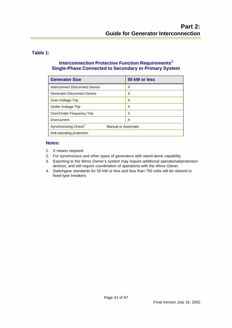
Table 1:
Interconnection Protective Function Requirements1
Single-Phase Connected to Secondary or Primary System
Generator Size 50 kW or less
Interconnect Disconnect Device X
Generator Disconnect Device X
Over-Voltage Trip X
Under-Voltage Trip X
Over/Under Frequency Trip X
Overcurrent X
Synchronizing Check2 Manual or Automatic
Anti-islanding protection
Notes:
1. X means required.2. For synchronous and other types of generators with stand-alone capability.3. Exporting to the Wires Owner’s system may require additional operational/protection
devices, and will require coordination of operations with the Wires Owner.4. Switchgear standards for 50 kW or less and less than 750 volts will be relaxed to
fixed-type breakers.

Part 2:Guide for Generator Interconnection
Page 42 of 67Final Version July 16, 2002
Table 2:
Interconnection Protective Function Requirements5
Three-Phase Connected to Secondary or Primary System
LARGEGenerator size classifications: MEDIUM
SMALL10 kW 10 kW - 200 kW - 500 - 2,000 - 12 500 - or less 200 kW 500 kW 2,000 kW 12,500 kW 50 000 kW
Device #Interconnect Disconnect Device X X X X X X
Generator Disconnect Device X X X X X X
25 Synchronizing Check(note 1) Y Y Y Y Y YMan. or Auto. Man. or Auto. Man. or Auto. Automatic Automatic Automatic
Qty: (1) (1) (1) (1) (1) (1)27 Under-Voltage Trip Y Y Y Y Y Y
Qty: (3) (3) (3) (3) (3) (3)32 Power Direction/Reverse Power Y(note 2) Y(note 2) Y(note 2) X(note 3) X(note 3)
Qty: (1) (1) (1) (1) (1)46 Negative Phase Sequence Overcurrent X X X X
(Phase unbalance, reverse phase sequence) (1) (1) (1)51V Overcurrent, voltage restrained X X X X X X
(Optional, to prevent nuisance trips) Qty: (1) (1) (1) (3) (3) (3)50/51 Inst/Timed Overcurrent X X X X X X
Qty: (3) (3) (3) (3) (3) (3)50N Instantaneous Neutral Overcurrent X X X X
Qty: (1) (1) (1) (1)Ground Over-Voltage Trip(note 6)
or X X X X51G Ground Over-Current Trip(note 6) Qty: (1) (1) (1) (1)
TT Transfer Trip(note 4) Y(note 4) Y(note 4) Y(note 4) Y(note 4) Y(note 4) Y(note 4)(Based on impact to IPP and utility)Telemetry data communication Y(note 4) Y(note 4) Y(note 4) Y(note 4)
Automatic Voltage Regulation (AVR)1 X XQty: (1) (1)
59I Instantaneous Over-Voltage Trip Y Y Y Y Y Y(For ferroresonance conditions) Qty: (3) (3) (3) (3) (3) (3)
59T Over-Voltage Trip Y Y Y Y Y YQty: (3) (3) (3) (3) (3) (3)
60 Voltage Balance Relay X(1)
67/67N Directional Overcurrent Y(note 2) Y(note 2) Y(note 2) Y(note 2) Y(note 2) Y(note 2)Qty: (3)/(1) (3)/(1) (3)/(1) (3)/(1) (3)/(1) (3)/(1)
81/O, 81/UOver/Under Frequency Trip Y Y Y Y Y YQty: (3) (3) (3) (3) (3) (3)
Anti-islanding for inverters Y Y Y Y Y YIEEE 929 and UL 1741
Part 2:Guide for Generator Interconnection
Page 43 of 67Final Version July 16, 2002
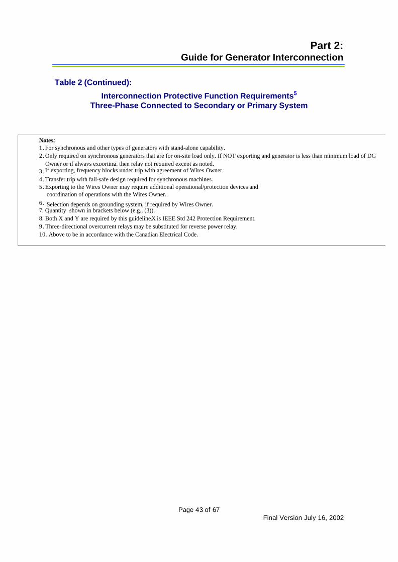
Table 2 (Continued):
Interconnection Protective Function Requirements5
Three-Phase Connected to Secondary or Primary System
Notes:1. For synchronous and other types of generators with stand-alone capability.2. Only required on synchronous generators that are for on-site load only. If NOT exporting and generator is less than minimum load of DG Owner or if always exporting, then relay not required except as noted.3. If exporting, frequency blocks under trip with agreement of Wires Owner.4. Transfer trip with fail-safe design required for synchronous machines.5. Exporting to the Wires Owner may require additional operational/protection devices and
coordination of operations with the Wires Owner.6. Selection depends on grounding system, if required by Wires Owner.7. Quantity shown in brackets below (e.g., (3)).8. Both X and Y are required by this guideline.X is IEEE Std 242 Protection Requirement.9. Three-directional overcurrent relays may be substituted for reverse power relay.10. Above to be in accordance with the Canadian Electrical Code.

Part 2:Guide for Generator Interconnection
Page 44 of 67Final Version July 16, 2002
Table 3:
Interconnection Protective Function RequirementsGenerators Connected to Secondary or Primary System
For 6 cycles or less (Closed Transition Switching)
Generator Size 10 MW or less
Interconnect Disconnect Device X
Generator Disconnect Device X
Over-Voltage Trip X
Under-Voltage Trip X
Over/Under Frequency Trip X
Overcurrent X
Ground Over-Voltage Trip1Or
Ground Over-Current Trip1
X
Synchronizing Check2 Manual or Automatic
Notes:
1. Selection depends on grounding system, if required by the Wires Owner.2. For synchronous and other types of generators with stand-alone capability.

Alberta Distributed GenerationInterconnection Guide
Page 45 of 67 Final Version July 16, 2002
Appendices
In this part…Appendix A: Approval Process Block DiagramAppendix B: Information Required From DG OwnerAppendix C: Information Provided by Wires OwnerAppendix D: Joint Operating AgreementAppendix E Applicable Codes and StandardsAppendix F: Single Line Diagram For Wye-Delta ............InterconnectionAppendix G: Single Line Diagram For Wye-Wye InterconnectionAppendix H: Protective Settings Commissioning DocumentAppendix I: Accuracy Schedules for Metering Equipment

Appendices
Page 46 of 67Final Version July 16, 2002
Appendix A: Approval Process Block DiagramOverview of Approval Process forConnecting Distributed Generation
(DG) to the Distribution System
Note: Process assumes DGOwner has internalproject approval
Notify Wires Ownerof project
Supply requested information
Request proposal forinterconnection from
Wires Owner
Notify TA if DG impactstransmission system
If > 1 MW
Complete and submitfull AEUB / AENN
applications
No
Receive proposaland cost estimate
Wires Owner and DGOwner submit applicationto TA with DG Owner's$10,000 refundable fee
Complete and submitone-page application
to AEUB G-XXXX
Receive approvalfrom AEUB / AENV
Approve WiresOwner’s proposal
Contact Power Pool,submit Pool
Participation applicationfor $150
Comply with WiresOwner’s application
process andpayment schedule
(See Note A.) Send in Pool AssetAddition application
Pool issues Asset ID#
Accepted> 5 MW
Provide copy ofAEUB / AENVapproval and
connection ordersto Wires Owner
Real time monitoringnot normally required
=< 5MW
Real time monitoringrequired; DG asset is
dispatchable by the PowerPool
Submit MeasurementCanada (MC)
application to register
Receive registrationnumber and certificate
Accepted
Execute anyagreements
Install and commission DGfacilities with Wires Owner’sapproval and participation
Commence commercialoperation
Purchase MC revenue-approved meter
Install meter to MCinstallation standards
Meter electrical energy
Submit meteringdata to LSA
Submit metering datato TA
TA refunds fee to DGOwner
Yes
(See Appendix B.)
DG Owner sendssigning sheet from
Joint OperatingAgreement to AEUB
Retrieve revenuemetering data
First DGsite only
Once percompany,renewannually
By site
Receiveapproval fromAEUB / AENV
Note A:Wires Owners may have different processesfor the following:Ø Initial application.Ø Detail design and studies.Ø Construction of the interconnection.Ø Necessary approvals from the AEUB /
AENV.Ø Execution of Joint Operating Agreement.Ø Tariff payment.
1
2
3
11
12
13
14 15
16
4
17
518
19
27
620
28
29
2610
24 25
23
22
9
8
7
2130 31
To Box 13OperatingAgreement
OperatingAgreementfrom Box 5
Asset ID toWires Owner
Appendices
Page 47 of 67Final Version July 16, 2002
Notes on the Approval Process
Power Pool
To sell electric energy through the Power Pool of Alberta, a DG Owner must become a PoolParticipant. This involves signing a Participant contract, paying trading charges and signingan agreement with the Transmission Administrator. Importers and exporters must alsodemonstrate that they have service agreements for transmission between Alberta and theadjoining province, state or territory.
Joint Operating Agreement
A generic Joint Operating Agreement is provided in Appendix C. The DG Owner must contactthe Wires Owner to negotiate a Joint Operating Agreement for the specific interconnection.
AEUB Approval
For AEUB procedures, access the AEUB website at www.eub.ab.ca.
Appendices
Page 48 of 67Final Version July 16, 2002
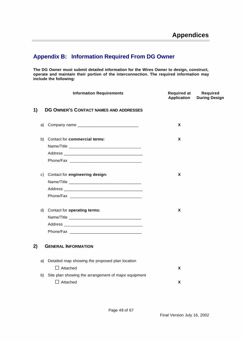
Appendix B: Information Required From DG Owner
The DG Owner must submit detailed information for the Wires Owner to design, construct,operate and maintain their portion of the interconnection. The required information mayinclude the following:
Information Requirements Required atApplication
RequiredDuring Design
1) DG OWNER'S CONTACT NAMES AND ADDRESSES
a) Company name ___________________________ X
b) Contact for commercial terms:
Name/Title ________________________________
Address ___________________________________
Phone/Fax ________________________________
X
c) Contact for engineering design:
Name/Title ________________________________
Address ___________________________________
Phone/Fax ________________________________
X
d) Contact for operating terms:
Name/Title ________________________________
Address ___________________________________
Phone/Fax ________________________________
X
2) GENERAL INFORMATION
a) Detailed map showing the proposed plan location
Attached X
b) Site plan showing the arrangement of major equipment
Attached X

Appendices
Page 49 of 67Final Version July 16, 2002
c) Diagram showing the voltage and current rating of eachcomponent
AttachedX
3) OPERATING CHARACTERISTICS
a) Indicate how the facility will operate.
The facility is intended to sell electric energy to the Power Pool.
The facility will consume electric energy services from the electric system.
X
4) GENERATOR
a) Type
Synchronous Induction Inverter
X
b) Manufacturer____________________ Model_____________ X
c) Nominal rating
_____________ kW
_____________ kVA
_____________ Volts
X
d) Single-Phase Three-Phase X
e) Governor droop ______________ % X
f) Generator connection configuration
Delta Wye
X
g) Generator grounding X
h) Impedances (positive, negative and zero sequence)
Direct axis transient _________________________
Direct axis subtransient _______________________
Quadrature axis transient _____________________
Quadrature axis subtransient ___________________
X
5) PRIME MOVER
a) Type__________________________ X
b) Manufacturer____________________ X
c) Model__________________________ X
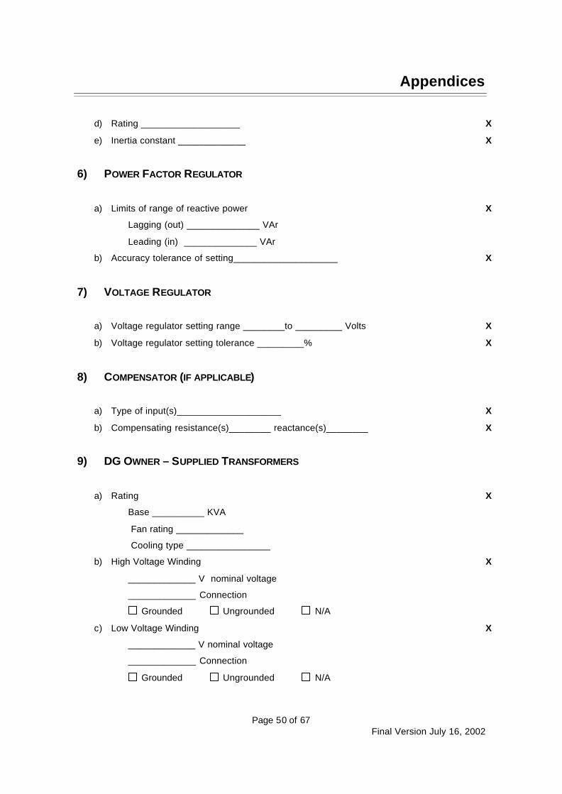
Appendices
Page 50 of 67Final Version July 16, 2002
d) Rating ___________________ X
e) Inertia constant _____________ X
6) POWER FACTOR REGULATOR
a) Limits of range of reactive power
Lagging (out) ______________ VAr
Leading (in) ______________ VAr
X
b) Accuracy tolerance of setting____________________ X
7) VOLTAGE REGULATOR
a) Voltage regulator setting range ________to _________ Volts X
b) Voltage regulator setting tolerance _________% X
8) COMPENSATOR (IF APPLICABLE)
a) Type of input(s)____________________ X
b) Compensating resistance(s)________ reactance(s)________ X
9) DG OWNER – SUPPLIED TRANSFORMERS
a) Rating
Base __________ KVA
Fan rating _____________
Cooling type ________________
X
b) High Voltage Winding
_____________ V nominal voltage
_____________ Connection
Grounded Ungrounded N/A
X
c) Low Voltage Winding
_____________ V nominal voltage
_____________ Connection
Grounded Ungrounded N/A
X
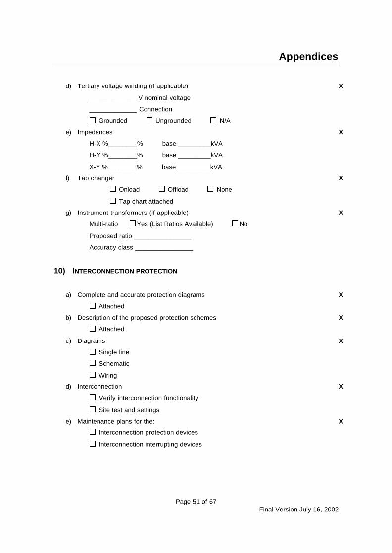
Appendices
Page 51 of 67Final Version July 16, 2002
d) Tertiary voltage winding (if applicable)
_____________ V nominal voltage
_____________ Connection
Grounded Ungrounded N/A
X
e) Impedances
H-X %________% base _________kVA
H-Y %________% base _________kVA
X-Y %________% base _________kVA
X
f) Tap changer
Onload Offload None
Tap chart attached
X
g) Instrument transformers (if applicable)
Multi-ratio Yes (List Ratios Available) No
Proposed ratio ________________
Accuracy class ________________
X
10) INTERCONNECTION PROTECTION
a) Complete and accurate protection diagrams
Attached
X
b) Description of the proposed protection schemes
Attached
X
c) Diagrams
Single line
Schematic
Wiring
X
d) Interconnection
Verify interconnection functionality
Site test and settings
X
e) Maintenance plans for the:
Interconnection protection devices
Interconnection interrupting devices
X
Appendices
Page 52 of 67Final Version July 16, 2002
11) COMPLIANCE WITH SAFETY CODES ACT
Permit or equivalent X
12) METERING
2 Element 3 Element
Meter service provider ______________________
Meter data manager ________________________
Asset ID # _________________________________
X
X
X
X
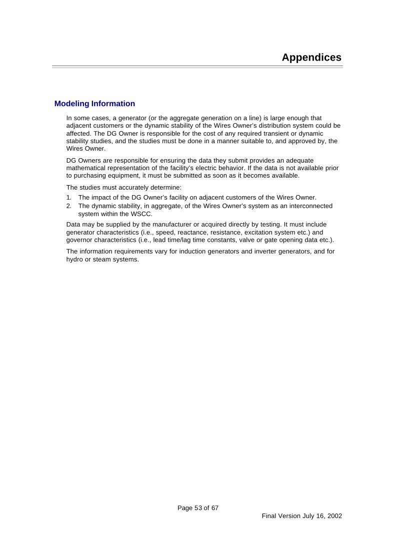
Appendices
Page 53 of 67Final Version July 16, 2002
Modeling Information
In some cases, a generator (or the aggregate generation on a line) is large enough thatadjacent customers or the dynamic stability of the Wires Owner’s distribution system could beaffected. The DG Owner is responsible for the cost of any required transient or dynamicstability studies, and the studies must be done in a manner suitable to, and approved by, theWires Owner.
DG Owners are responsible for ensuring the data they submit provides an adequatemathematical representation of the facility’s electric behavior. If the data is not available priorto purchasing equipment, it must be submitted as soon as it becomes available.
The studies must accurately determine:
1. The impact of the DG Owner’s facility on adjacent customers of the Wires Owner.2. The dynamic stability, in aggregate, of the Wires Owner’s system as an interconnected
system within the WSCC.
Data may be supplied by the manufacturer or acquired directly by testing. It must includegenerator characteristics (i.e., speed, reactance, resistance, excitation system etc.) andgovernor characteristics (i.e., lead time/lag time constants, valve or gate opening data etc.).
The information requirements vary for induction generators and inverter generators, and forhydro or steam systems.
Appendices
Page 54 of 67Final Version July 16, 2002
Appendix C: Joint Operating Agreement
This template is generic. Each Wires Owner will use their own specific format.
INTERCONNECTION and OPERATING AGREEMENT
between
__________________________________ (the DG Owner)and
__________________________________ (the Wires Owner)
This Agreement provides for the safe and orderly operation of the electrical facilitiesinterconnecting the DG Owner’s generation facility at (land location or description of project)and the electrical distribution system owned by the Wires Owner.
This Agreement does not supersede any requirements outlined in Government Regulations suchas (but not limited to) the Alberta Electric and Communication Utility Code, the CanadianElectrical Code and the Occupational Health and Safety Act; nor does it supersede any terms ofthe Commercial Contract between the DG Owner and the Wires Owner.
1. Intent of Parties: It is the intent of (the DG Owner) to generate for sale to the Power Pool ofAlberta up to the maximum available power, and to dispatch the amount of power producedat their discretion.
It is the intent of the Wires Owner to operate the distribution system to maintain a high levelof service to their customers and to maintain a high level of power quality.
It is the intent of both parties to operate the facilities in a way that ensures the safety of thepublic and their employees.
2. Operating Authority: The Operating Authority is the person identified by name or job titleresponsible to establish operating procedures and standards within their organization. TheOperating Authority shall ensure that timely updates are made to this document to reflect anychanges to system operating characteristics, disconnect devices and Single Line Diagramsreferenced in this document. The Operating Authorities for the DG Owner and for the WiresOwner shall ensure that the operators of the generation facility and the distribution systemare competent in the operation of the electrical systems and are aware of the provisions ofany operating agreements and regulations relating to the safe operation of electrical powersystems.
The Operating Authority for (the DG Owner) is (name or title of person designated theOperating Authority, their address and phone numbers).
The Operating Authority for the Wires Owner is (name or title of person designated theOperating Authority, their address and phone numbers).
Appendices
Page 55 of 67Final Version July 16, 2002
3. Operator in Charge : The Operator in Charge is the person identified by name or job titleresponsible for the real time operation of all electrical facilities related to the interconnectionand owned by their organization.
The Operator in Charge for (the DG Owner) is (name or title of person designated theOperator in Charge, their address and phone numbers).
The Operator in Charge for the Wires Owner is (name or title of person designated theOperator in Charge, their address and phone numbers).
4. Description: (The DG Owner’s) facilities consist of a (size), (type), (connection) generatorconnected to the distribution system through the main bus at the facility. (The DG Owner)owns and is responsible for the maintenance and operation of all facilities on the generatorside of (the Point of Common Coupling).
The Wires Owner’s distribution system consists of 25 kV line (line number) and a(transformer size), (transformer connection designation) transformer. The Wires Ownerowns and is responsible for the operation of all facilities on the distribution side of (the Pointof Common Coupling).
The Point of Common Coupling is designated as (description of Point of CommonCoupling), and is identified on the attached Single Line Diagram.
The (breaker, switch etc.) (switch number) will be used as the main disconnect point forthe facility, and is owned and operated by (the DG Owner or the Wires Owner). This switch(does/does not) have load-break capability and therefore (can/cannot) be operated whilethe generation facility is producing or consuming power.
The generation facility is designed to operate connected to the grid, with synchronizingfacilities provided on the DG Owner’s breaker (breaker number). In the absence ofoutstanding clearances between the Operators in Charge, notice is not required to be givento the Wires Owner prior to synchronization taking place. It is recognized by (the DG Owner)that there are no synchronization schemes in place on the Wires Owner’s system, and thatthe (upstream distribution facility) contains automatic equipment that will provide forvoltage regulation or automatic reclosure under some conditions. (Insert description of anyspecial blocking or protection schemes.)
The generator is capable of controlling either voltage or power factor, and is normally set tocontrol (voltage or power factor) to (setting, tolerance) at the generator terminals.(Islanded capabilities to be identified here also, if any).
5. Suspension of Interconnection: It is intended that the interconnection will not compromisethe Wires Owner’s protection or operational requirements. The operation of the (DGOwner’s) facilities and the quality of electric energy supplied by (the DG Owner) shall meetthe standards specified in Part 2 of the Alberta Distributed Generation Interconnection Guideand any further standards identified by the Wires Owner. If the operation of the (DGOwner’s) facilities or quality of electric energy supplied does not meet the standards asspecified, then the Wires Owner will notify (the DG Owner) to take reasonable andexpedient corrective action. The Wires Owner shall have the right to disconnect the (DGOwner’s) facilities until compliance is reasonably demonstrated. Notwithstanding, the WiresOwner may, in its sole discretion, disconnect the (DG Owner’s) generation facility from thedistribution system without notice if the operation of the generation facility may be or maybecome dangerous to life and property.
Appendices
Page 56 of 67Final Version July 16, 2002
6. Safe Work Planning: Safe work planning practices such as pre-job plans and tailboardconference procedures shall be followed whenever both parties are involved in work on theinterconnected system. Nothing in this document should be interpreted as altering the intentof the Wires Owner’s safe practices manual or safe operating procedures. Anycontradictions are to be identified and resolved prior to work commencing.
Safe work routines described in Division D of the Electrical and Communication UtilitySystems Regulations (AECUC) shall be followed when providing isolation for work on anypart of the interconnected system.
7. Maintenance Outages: Maintenance outages will occasionally be required on the WiresOwner’s distribution system and the (DG Owner’s) facilities. Both parties are required toprovide as much notice as possible and plan to minimize downtime. It is recognized that insome emergency cases, such notice may not be possible. Outages shall be coordinated bythe Operators in Charge of the respective facilities.
8. Access: The Wires Owner shall have access to the (DG Owner’s) facilities for maintenance,operating and meter reading purposes. The Wires Owner may inspect the (DG Owner’s)facilities, and (the DG Owner) may inspect the Wires Owner’s facilities. Access orinspections shall be arranged by the Operators in Charge of the respective facilities.
9. Revision and Approval: This Agreement does not expire. Either party may cancel theAgreement with reason, after giving notice to the Operating Authority designated by the otherparty.
APPROVED by:
Wires Owner Operating Authority DG Owner Operating Authority
Date Date
Appendices
Page 57 of 67Final Version July 16, 2002
Appendix D: Information Provided by Wires Owner
After receiving the application for interconnection, the Wires Owner must provide thefollowing information to the DG Owner, on request:
1. Single Line Diagram or maps of the distribution system to the Point of CommonCoupling (PCC).
2. Minimum and maximum 60 Hz source impedances (positive-sequence, negative-sequence and zero-sequence) at the PCC.
3. Maximum and minimum normal and emergency system operating voltage ranges atthe PCC.
4. Harmonic impedance envelope at the PCC.5. Planning, operating and reliability criteria, standards and policies.6. The results of a planning study documenting the availability of the requested amount
of system capacity.7. Cost estimates and time schedule to build the upstream facilities.8. Clearing and reclosing times for single-phase and multiple-phase faults occurring on
the distribution system.9. Characteristics and settings of protection on the distribution system.10. Costs of studies and any required changes to the distribution system.
Some or all of this information will be required by the DG Owner to properly design theinterconnection protection. The Wires Owner will identify when the costs of producingthis information are to be assigned to the DG Owner.

Appendices
Page 58 of 67Final Version July 16, 2002
Appendix E: Applicable Codes and Standards
The distributed generation (DG) and interconnection facilities must conform to this Guideand to the applicable sections of the codes and standards listed below. When the statedversion of the code or standard is superseded by an approved revision, then that revisionshall apply.
Specific types of interconnection schemes, DG technologies, and distribution systemsmay be subject to additional requirements, standards, recommended practices orguidelines external to this Guide. Determining the applicability and hierarchy of thoserequirements in relation to the requirements herein is beyond the scope of this Guide.Therefore, the following list of codes and standards is not to be regarded as all-inclusive,and users of this Guide must address related concerns.
Power Quality Standards
1. ANSI C84.1-1989 American National Standards for Electric Power Systems andEquipment Ratings (60 Hertz). Establishes nominal voltage ratings and operatingtolerances for 60 Hz electric power systems from 100 V through 230 kV.
2. IEEE Std. 493-1900 IEEE Recommended Practice for Design of Reliable Industrialand Commercial Power Systems (IEEE Gold Book). Chapter 9 deals specifically withvoltage sag analysis and methods of reporting sag characteristics graphically andstatistically.
3. IEEE Std 519-1992 IEEE Recommended Practice and Requirements for HarmonicControl in Electric Power Systems.
4. IEEE Std. 1100-1992 IEEE Recommended Practice for Powering and GroundingSensitive Electronic Equipment (IEEE Emerald Book).
5. IEEE Std 1159-1995 IEEE Recommended Practice for Monitoring Electric PowerQuality.
6. IEEE Std 1250-1995 IEEE Guide for Service to Equipment Sensitive to MomentaryVoltage Disturbances.
In addition to the power quality standards, the following standards are applicable to theinterconnection of generation facilities to the Wires Owner’s distribution system:
7. IEEE Std. 100 - 1997 IEEE Standard Dictionary of Electrical and Electronics Terms.8. IEEE Std 315-1975 (Reaffirmed 1993) ANSI Y32.3-1975 (Reaffirmed 1989) CSA
Z99-1975 Graphic Symbols for Electrical and Electronics Diagrams (includingReference Designation Letters).
9. IEEE Std 929-1988 IEEE Recommended Practice for Utility Interface of Residentialand Intermediate Photovoltaic (PV) Systems.
10. C37.1 ANSI/IEEE Standard Definitions, Specifications and Analysis of Systems Usedfor Supervisory Control, Data Acquisition and Automatic Control.
11. C37.2 IEEE Standard Electrical Power System Device Function Numbers.12. C37.18 ANSI/IEEE Standard Enclosed Field Discharge Circuit Breakers for Rotating
Electric Machinery.13. C37.20.1 ANSI/IEEE Standard for Metal-Enclosed Low-Voltage Power Circuit
Breakers Switchgear.14. C37.20.3 ANSI/IEEE Standard for Metal-Enclosed Interrupter Switchgear.15. C37.24 ANSI/IEEE Standard for Radiation on Outdoor Metal-Enclosed Switchgear.16. C37.27 ANSI/IEEE Standard Application Guide for Low-Voltage AC Non-integrally
Fused Power Circuit Breakers (Using Separately Mounted Current-Limiting Fuses).
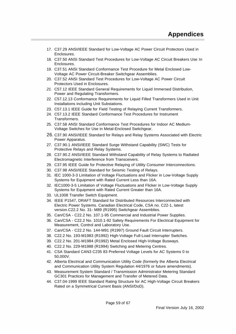
Appendices
Page 59 of 67Final Version July 16, 2002
17. C37.29 ANSI/IEEE Standard for Low-Voltage AC Power Circuit Protectors Used inEnclosures.
18. C37.50 ANSI Standard Test Procedures for Low-Voltage AC Circuit Breakers Use InEnclosures.
19. C37.51 ANSI Standard Conformance Test Procedure for Metal Enclosed Low-Voltage AC Power Circuit-Breaker Switchgear Assemblies.
20. C37.52 ANSI Standard Test Procedures for Low-Voltage AC Power CircuitProtectors Used in Enclosures.
21. C57.12 IEEE Standard General Requirements for Liquid Immersed Distribution,Power and Regulating Transformers.
22. C57.12.13 Conformance Requirements for Liquid Filled Transformers Used in UnitInstallations including Unit Substations.
23. C57.13.1 IEEE Guide for Field Testing of Relaying Current Transformers.24. C57.13.2 IEEE Standard Conformance Test Procedures for Instrument
Transformers.25. C37.58 ANSI Standard Conformance Test Procedures for Indoor AC Medium-
Voltage Switches for Use in Metal-Enclosed Switchgear.
26. C37.90 ANSI/IEEE Standard for Relays and Relay Systems Associated with ElectricPower Apparatus.
27. C37.90.1 ANSI/IEEE Standard Surge Withstand Capability (SWC) Tests forProtective Relays and Relay Systems.
28. C37.90.2 ANSI/IEEE Standard Withstand Capability of Relay Systems to RadiatedElectromagnetic Interference from Transceivers.
29. C37.95 IEEE Guide for Protective Relaying of Utility Consumer Interconnections.30. C37.98 ANSI/IEEE Standard for Seismic Testing of Relays.31. IEC 1000-3-3 Limitation of Voltage Fluctuations and Flicker in Low-Voltage Supply
Systems for Equipment with Rated Current Less than 16A.32. IEC1000-3-5 Limitation of Voltage Fluctuations and Flicker in Low-Voltage Supply
Systems for Equipment with Rated Current Greater than 16A.33. UL1008 Transfer Switch Equipment.34. IEEE P1547, DRAFT Standard for Distributed Resources Interconnected with
Electric Power Systems. Canadian Electrical Code, CSA no. C22-1, latestversion.C22.2 No. 31- M89 (R1995) Switchgear Assemblies.
35. Can/CSA - C22.2 No. 107.1-95 Commercial and Industrial Power Supplies.36. Can/CSA - C22.2 No. 1010.1-92 Safety Requirements For Electrical Equipment for
Measurement, Control and Laboratory Use.37. Can/CSA - C22.2 No. 144-M91 (R1997) Ground Fault Circuit Interrupters.38. C22.2 No. 193-M1983 (R1992) High-Voltage Full-Load Interrupter Switches.39. C22.2 No. 201-M1984 (R1992) Metal Enclosed High-Voltage Busways.40. C22.2 No. 229-M1988 (R1994) Switching and Metering Centres.41. CSA Standard CAN3 C235 83 Preferred Voltage Levels for AC Systems 0 to
50,000V.42. Alberta Electrical and Communication Utility Code (formerly the Alberta Electrical
and Communication Utility System Regulation 44/1976 or future amendments).43. Measurement System Standard / Transmission Administrator Metering Standard
GC301 Practices for Management and Transfer of Metered Data.44. C37.04-1999 IEEE Standard Rating Structure for AC High-Voltage Circuit Breakers
Rated on a Symmetrical Current Basis (ANSI/DoD).
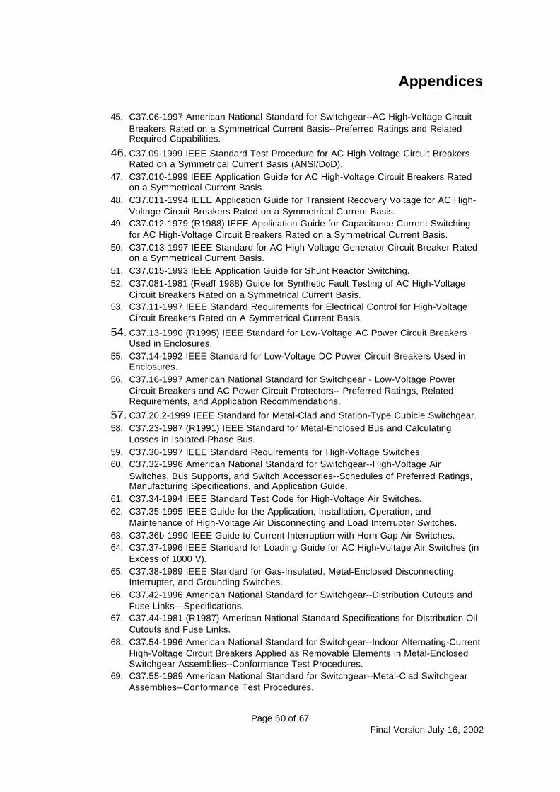
Appendices
Page 60 of 67Final Version July 16, 2002
45. C37.06-1997 American National Standard for Switchgear--AC High-Voltage CircuitBreakers Rated on a Symmetrical Current Basis--Preferred Ratings and RelatedRequired Capabilities.
46. C37.09-1999 IEEE Standard Test Procedure for AC High-Voltage Circuit BreakersRated on a Symmetrical Current Basis (ANSI/DoD).
47. C37.010-1999 IEEE Application Guide for AC High-Voltage Circuit Breakers Ratedon a Symmetrical Current Basis.
48. C37.011-1994 IEEE Application Guide for Transient Recovery Voltage for AC High-Voltage Circuit Breakers Rated on a Symmetrical Current Basis.
49. C37.012-1979 (R1988) IEEE Application Guide for Capacitance Current Switchingfor AC High-Voltage Circuit Breakers Rated on a Symmetrical Current Basis.
50. C37.013-1997 IEEE Standard for AC High-Voltage Generator Circuit Breaker Ratedon a Symmetrical Current Basis.
51. C37.015-1993 IEEE Application Guide for Shunt Reactor Switching.52. C37.081-1981 (Reaff 1988) Guide for Synthetic Fault Testing of AC High-Voltage
Circuit Breakers Rated on a Symmetrical Current Basis.53. C37.11-1997 IEEE Standard Requirements for Electrical Control for High-Voltage
Circuit Breakers Rated on A Symmetrical Current Basis.
54. C37.13-1990 (R1995) IEEE Standard for Low-Voltage AC Power Circuit BreakersUsed in Enclosures.
55. C37.14-1992 IEEE Standard for Low-Voltage DC Power Circuit Breakers Used inEnclosures.
56. C37.16-1997 American National Standard for Switchgear - Low-Voltage PowerCircuit Breakers and AC Power Circuit Protectors-- Preferred Ratings, RelatedRequirements, and Application Recommendations.
57. C37.20.2-1999 IEEE Standard for Metal-Clad and Station-Type Cubicle Switchgear.58. C37.23-1987 (R1991) IEEE Standard for Metal-Enclosed Bus and Calculating
Losses in Isolated-Phase Bus.59. C37.30-1997 IEEE Standard Requirements for High-Voltage Switches.60. C37.32-1996 American National Standard for Switchgear--High-Voltage Air
Switches, Bus Supports, and Switch Accessories--Schedules of Preferred Ratings,Manufacturing Specifications, and Application Guide.
61. C37.34-1994 IEEE Standard Test Code for High-Voltage Air Switches.62. C37.35-1995 IEEE Guide for the Application, Installation, Operation, and
Maintenance of High-Voltage Air Disconnecting and Load Interrupter Switches.63. C37.36b-1990 IEEE Guide to Current Interruption with Horn-Gap Air Switches.64. C37.37-1996 IEEE Standard for Loading Guide for AC High-Voltage Air Switches (in
Excess of 1000 V).65. C37.38-1989 IEEE Standard for Gas-Insulated, Metal-Enclosed Disconnecting,
Interrupter, and Grounding Switches.66. C37.42-1996 American National Standard for Switchgear--Distribution Cutouts and
Fuse Links—Specifications.67. C37.44-1981 (R1987) American National Standard Specifications for Distribution Oil
Cutouts and Fuse Links.68. C37.54-1996 American National Standard for Switchgear--Indoor Alternating-Current
High-Voltage Circuit Breakers Applied as Removable Elements in Metal-EnclosedSwitchgear Assemblies--Conformance Test Procedures.
69. C37.55-1989 American National Standard for Switchgear--Metal-Clad SwitchgearAssemblies--Conformance Test Procedures.

Appendices
Page 61 of 67Final Version July 16, 2002
70. C37.57-1990 American National for Switchgear--Metal-Enclosed InterrupterSwitchgear Assemblies--Conformance Testing.
71. C37.66-1969 (Reaff 1988) American National Standard for Requirements for Oil-Filled Capacitor Switches for Alternating-Current Systems.
72. C37.81-1989 (R1992) IEEE Guide for Seismic Qualification of Class 1E Metal-Enclosed Power Switchgear Assemblies.
73. C37.85-1989 (R1998) American National Standard for Switchgear--Alternating-Current High-Voltage Power Vacuum Interrupters-Safety Requirements for X-Radiation Limits.
74. ANSI/IEEE C37.90-1989 Surge Withstand And Fast Transient Tests.75. 120-1989 (Reaff-1997) IEEE Master Test Guide for Electrical Measurements in
Power Circuits.76. 1291-1993 IEEE Guide for Partial Discharge Measurement in Power Switchgear.77. IEEE Std C62.23-1995 Application Guide for Surge Protection of Electric Generating
Plants.78. ANSI /IEEE C62.41-1991 Recommended Practices on Surge Voltages in Low-
Voltage AC Power Circuits.79. C57.13-1993 IEEE Standard Requirements for Instrument Transformers.80. C57.13.3-1983 (R1991) IEEE Guide for the Grounding of Instrument Transformer
Secondary Circuits and Cases.81. C57.98-1993 IEEE Guide for Transformer Impulse Tests.82. C57.19.100-1995 (R1997) IEEE Guide for Application of Power Apparatus Bushings.83. C57.110-1986 (R1992) IEEE Recommended Practice for Establishing Transformer
Capability When Supplying Nonsinusoidal Load Currents.84. C62.92.4-1991 IEEE Guide for the Application of Neutral Grounding in Electrical
Utility Systems, Part IV – Distribution.85. IEEE Std 242-1986 Recommended Practice for Protection and Coordination of
Industrial and Commercial Power Systems.86. ANSI C12.20 Electricity Meters 0.2 And 0.5 Accuracy Classes.87. ANSI C62.1 Surge Arresters for AC Power Circuits.88. ANSI C62.11 Metal-Oxide Surge Arresters for AC Power Circuits.89. NEMA CC-1 Electric Power Connectors for Substations.90. NEMA LA-1 Surge Arresters.91. NEMA MG-1 Motors.

Appendices
Page 62 of 67Final Version July 16, 2002
Appendix F: Single Line Diagram for Wye-Delta Interconnection
S1SOURCE
TRANSFER TRIP TOIPP BREAKER A OR B
[NOTE 5]
OCR
OIL OR ELECTRICCIRCUIT RECLOSER
TRANSFER TRIP TOIPP BREAKER A OR B
[NOTE 5]
AIRBREAK[NOTE 1]
[NOTE 4]
51GVISIBLE LOCKABLESWITCH WITHIN 5M
OF POINT OFCOMMON COUPLING
[NOTE 1]
D
PROTECTION LEGEND
25 – Synchronism Check
27 – Under Voltage
27R – Instantaneous Under Voltage
32 – Reverse Power
40 – Loss of Field
46 – Negative Phase Sequence O/C
47 – Reverse phase Voltage
49 – Stator Winding Temperature
50/51 – Instantaneous/Timed Overcurrent
50N – Ground Overcurrent
51G – Neutral Overcurrent
51V – Torque Controlled Overcurrent
59I – High Speed Overvoltage
59T – TimeOvervoltage
60 – Voltage Balance Relay
64F – Generator Field Ground
67 – DirectionalOvercurrent
67N – Neutral DirectionalOvercurrent
81/O – Over Frequency
81/U – Under Frequency
87 (G) – Differential Relay (Ground)
NOTES:1. Use one or other for simultaneous 3-
phase switching. Simultaneous 3-phase switchingis not required for non-export static powerconverters or induction generators notsusceptible to self-excitation.
2. Required only if ferroresonance ispossible.
3. Required if 27 operating time is tooslow for feeder faults.
4.Use one or other only if feederunbalance can cause transformer overloading.
5. FOR EXPORT ONLY. For synchronousgenerators and generator susceptible to selfexcitation (induction & static power converters).
6. FOR NON-EXPORT ONLY; must sense bothreal and reactive power. Three 67 relays and one67N relay may be required, as well.
7. To suppress a possible ferroresonance conditionwhen the low voltage system is operated,generator must be effectively grounded, orsolidly grounded.
8. Number and location of the metering points bycommercial parameters.
9. Required if feeder load unbalance will overloadtransformer.
LEGEND:
Circuit Breaker
Manual Air Break
Transformer
DG SLD FORINTERCONNECTION THROUGH
WYE-DELTA TRANSFORMERDATE BY SLD NO.
11/22/2001 00-001
50/51
(3)
50N
(1)
SHUNT TRIPRECLOSER
[NOTE 9]
Fuse
Metering
(x) Number Required
Local Load
A
C
[NOTE 8]
B
G
87 87G 49
64F
51V
40
32 4660
51G
59T 81/O 81/U
WIRES OWNER
27 25
59I[NOTE 2]
[NOTE 3][NOTE 6]
[NOTE 8]
[NOTE 8]
Neutral GroundingResistor (NGR)
NGR[NOTE 7]
NOTE: PROTECTION SCHEMATIC SHOWN IS FOR LARGE 3-PHASE GENERATORSOVER 12 500 KVA. REFER TO TABLE 2 FOR REQUIREMENTS ON SPECIFIC GENERATORS.
27R
Wires Owner
DG Owner
47 67
INTERCONNECTION PROTECTION
[NOTE 6]

Appendices
Page 63 of 67Final Version July 16, 2002
Appendix G: Single Line Diagram For Wye-Wye Interconnection
S1SOURCE
TRANSFER TRIP TOIPP BREAKER A OR B
[NOTE 5]
OCR
OIL OR ELECTRICCIRCUIT RECLOSER
TRANSFER TRIP TOIPP BREAKER A OR B
[NOTE 5]
AIRBREAK[NOTE 1]
[NOTE 4]
51GVISIBLE LOCKABLESWITCH WITHIN 5M
OF POINT OFCOMMON COUPLING
[NOTE 1]
PROTECTION LEGEND
25 – Synchronism Check
27 – Under Voltage
27R – Instantaneous Under Voltage
32 – Reverse Power
40 – Loss of Field
46 – Negative Phase Sequence O/C
47 – Reverse Phase Voltage
49 – Stator Winding Temperature
50/51 – Instantaneous/Timed Overcurrent
50N – Ground Overcurrent
51G – Neutral Overcurrent
51V – Torque Controlled Overcurrent
59I – High Speed Overvoltage
59T – Time Overvoltage
60 – Voltage Balance Relay
64F – Generator Field Ground
67 – Directional Overcurrent
67N – Neutral Directional Overcurrent
81/O – Over Frequency
81/U – Under Frequency
87 (G) – Differential Relay (Ground)
NOTES:1. Use one or other for simultaneous 3
phase switching. Simultaneous 3 phase switchingis not required for non-export static powerconverters or induction generators notsusceptible to self-excitation.
2. Relay required only if ferroresonance ispossible.
3. Required if 27 operating time is tooslow for feeder faults.
4.Use one or other only if feederunbalance can cause transformer overloading.
5. FOR EXPORT ONLY. For synchronousgenerators and generator susceptible to selfexcitation (induction & static power converters).
6. FOR NON-EXPORT ONLY; must sense bothreal and reactive power. Three 67 relays and one67N relay may be required, as well.
7. Generator must be effectively grounded. WithWires Owner approval can also be resistancegrounded at secondary system ground. Secondarysystem ground and generator ground aregenerally common.
8. Number and location of the metering points bycommercial parameters.
LEGEND:
Circuit Breaker
Manual Air Break
Transformer
DG SLD FORINTERCONNECTION THROUGH
WYE - WYE TRANSFORMER
DATE BY SLD NO.
11/22/2001 00-002
Fuse
Metering
(x) Number Required
Local Load
A
C
[NOTE 8]
B
G
4951V
40
32 4660 59T 81/O 81/U
WIRES OWNER
27 25
59I[NOTE 2]
[NOTE 3]
[NOTE 6]
[NOTE 8]
[NOTE 8]
Neutral Grounding Resistor (NGR)
To systemground[NOTE 7]
NOTE: PROTECTION SCHEMATIC SHOWN IS FOR LARGE 3 PHASE GENERATORSOVER 12 500 KVA. REFER TO TABLE 2 FOR REQUIREMENTS ON SPECIFIC GENERATORS.
27R
Wires Owner
Power Producer
64F
51
51N 47 67
INTERCONNECTION PROTECTION
[NOTE 6]
[NOTE 7]
~~
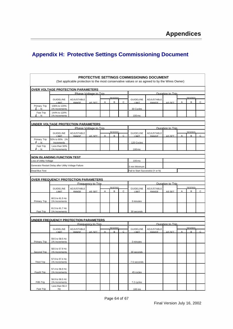
Appendices
Page 64 of 67Final Version July 16, 2002
Appendix H: Protective Settings Commissioning Document
OVER VOLTAGE PROTECTION PARAMETERS
A B C A B C
Primary Trip- N
106% to 120%1% Increments 30 Cycles
Fast Trip- N
144% to 120%1% Increments 100 ms
UNDER VOLTAGE PROTECTION PARAMETERS
A B C A B C
Primary Trip- N
50% to 90% 1%Increments 120 Cycles
Fast Trip- N
Less than 50%1% Increments 100 ms
NON ISLANDING FUNCTION TEST100 ms
5 min Minimum
OVER FREQUENCY PROTECTION PARAMETERS
A B C A B C
Primary Trip60.5 to 61.5 Hz1% Increments 3 minutes
Fast Trip61.5 to 61.7 Hz1% Increments 30 seconds
UNDER FREQUENCY PROTECTION PARAMETERS
A B C A B C
Primary Trip59.5 to 58.5 Hz1% Increments 3 minutes
Second Trip58.5 to 57.9 Hz1% Increments 30 seconds
Third Trip57.9 to 57.4 Hz1% Increments 7.5 seconds
Fourth Trip57.4 to 56.9 Hz1% Increments 45 cycles
Fifth Trip56.9 to 56.5 Hz1% Increments 7.2 cycles
Fast TripLess than 56.4
Hz 100 ms
AS SET
TESTED
Dead Bus Test
GUIDELINELIMIT
ADJUSTABLERANGE
Phase Voltage to Trip
TESTED
Loss of Utility Voltage
Generator Restart Delay after Utility Voltage Failure
TESTED
TESTED
Duration to Trip
AS SETGUIDELINE
LIMITADJUSTABLE
RANGE
GUIDELINELIMIT
ADJUSTABLERANGE AS SET
TESTED
Phase Voltage to Trip Duration to Trip
GUIDELINELIMIT
ADJUSTABLERANGE AS SET
Fail to Start Successful (Y or N)
AS SET
Frequency to Trip Duration to Trip
GUIDELINELIMIT
ADJUSTABLERANGE AS SET
TESTED GUIDELINELIMIT
ADJUSTABLERANGE AS SET
Frequency to Trip Duration to Trip
GUIDELINELIMIT
ADJUSTABLERANGE AS SET
TESTED GUIDELINELIMIT
ADJUSTABLERANGE
PROTECTIVE SETTINGS COMMISSIONING DOCUMENT(Set applicable protection to the most conservative values or as agreed to by the Wires Owner)
TESTED
0
0
0
0
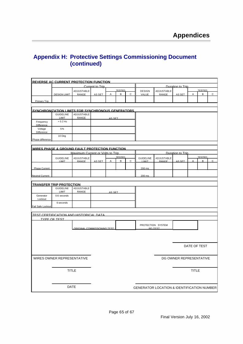
Appendices
Page 65 of 67Final Version July 16, 2002
Appendix H: Protective Settings Commissioning Document(continued)
REVERSE AC CURRENT PROTECTION FUNCTION
A B C A B C
Primary Trip
SYNCHRONIZATION LIMITS FOR SYNCHRONOUS GENERATORSGUIDELINE
LIMITADJUSTABLE
RANGE
FrequencyDifference
+ 0.2 Hz
VoltageDifference
5%
Phase difference10 Deg
WIRES PHASE & GROUND FAULT PROTECTION FUNCTION
A B C A B C
Phase Current 200 ms
Neutral Current 200 ms
TRANSFER TRIP PROTECTIONGUIDELINE
LIMITADJUSTABLE
RANGE
GeneratorLockout
0.6 seconds
Fail Safe Lockout6 seconds
TEST CERTIFICATION AND HISTORICAL DATA
GENERATOR LOCATION & IDENTIFICATION NUMBER
TESTEDTESTED DESIGNVALUE
ADJUSTABLERANGE AS SET
AS SET
Current to Trip Duration to Trip
DESIGN LIMITADJUSTABLE
RANGE AS SET
Maximum Current or Volts to Trip Duration to TripGUIDELINE
LIMITADJUSTABLE
RANGE AS SET
TESTED ADJUSTABLERANGE AS SET
TESTEDGUIDELINELIMIT
AS SET
TYPE OF TEST
PROTECTION SYSTEMRE-TEST
DATE OF TEST
DATE
ORIGINAL COMMISSIONING TEST
DG OWNER REPRESENTATIVE
TITLE
WIRES OWNER REPRESENTATIVE
TITLE
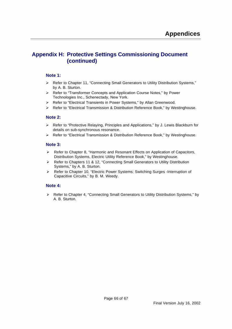
Appendices
Page 66 of 67Final Version July 16, 2002
Appendix H: Protective Settings Commissioning Document(continued)
Note 1:
Ø Refer to Chapter 11, “Connecting Small Generators to Utility Distribution Systems,”by A. B. Sturton.
Ø Refer to “Transformer Concepts and Application Course Notes,” by PowerTechnologies Inc., Schenectady, New York.
Ø Refer to “Electrical Transients in Power Systems,” by Allan Greenwood.Ø Refer to “Electrical Transmission & Distribution Reference Book,” by Westinghouse.
Note 2:
Ø Refer to “Protective Relaying, Principles and Applications,” by J. Lewis Blackburn fordetails on sub-synchronous resonance.
Ø Refer to “Electrical Transmission & Distribution Reference Book,” by Westinghouse.
Note 3:
Ø Refer to Chapter 8, “Harmonic and Resonant Effects on Application of Capacitors,Distribution Systems, Electric Utility Reference Book,” by Westinghouse.
Ø Refer to Chapters 11 & 12, “Connecting Small Generators to Utility DistributionSystems,” by A. B. Sturton.
Ø Refer to Chapter 10, “Electric Power Systems: Switching Surges -Interruption ofCapacitive Circuits,” by B. M. Weedy.
Note 4:
Ø Refer to Chapter 4, “Connecting Small Generators to Utility Distribution Systems,” byA. B. Sturton.
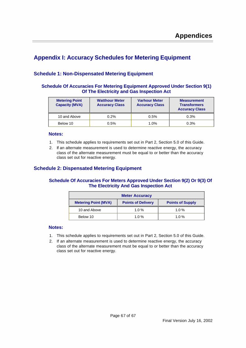
Appendices
Page 67 of 67Final Version July 16, 2002
Appendix I: Accuracy Schedules for Metering Equipment
Schedule 1: Non-Dispensated Metering Equipment
Schedule Of Accuracies For Metering Equipment Approved Under Section 9(1)Of The Electricity and Gas Inspection Act
Metering PointCapacity (MVA)
Watthour MeterAccuracy Class
Varhour MeterAccuracy Class
MeasurementTransformers
Accuracy Class
10 and Above 0.2% 0.5% 0.3%
Below 10 0.5% 1.0% 0.3%
Notes:
1. This schedule applies to requirements set out in Part 2, Section 5.0 of this Guide.2. If an alternate measurement is used to determine reactive energy, the accuracy
class of the alternate measurement must be equal to or better than the accuracyclass set out for reactive energy.
Schedule 2: Dispensated Metering Equipment
Schedule Of Accuracies For Meters Approved Under Section 9(2) Or 9(3) OfThe Electricity And Gas Inspection Act
Meter Accuracy
Metering Point (MVA) Points of Delivery Points of Supply
10 and Above 1.0 % 1.0 %
Below 10 1.0 % 1.0 %
Notes:
1. This schedule applies to requirements set out in Part 2, Section 5.0 of this Guide.2. If an alternate measurement is used to determine reactive energy, the accuracy
class of the alternate measurement must be equal to or better than the accuracyclass set out for reactive energy.