all hakuna resort photos in courtesy of lmn development llc young jeon structural option advisor:...
TRANSCRIPT

All Hakuna Resort photos in courtesy of LMN Development LLC
Young JeonStructural Option
Advisor: Heather Sustersic
Hakuna ResortAE Senior Thesis 2015

Presentation Outline
Introduction
Existing Structure
Thesis Topics
Structural Depth
Architectural Breadth
Conclusion
I
E
T
S
A
C
Building Statistics
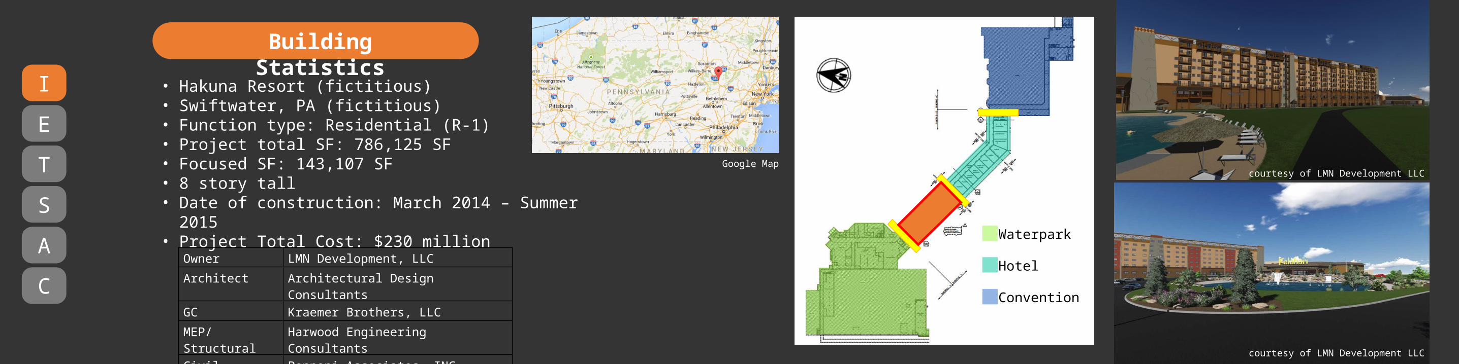
• Hakuna Resort (fictitious)• Swiftwater, PA (fictitious)• Function type: Residential (R-1)• Project total SF: 786,125 SF• Focused SF: 143,107 SF• 8 story tall• Date of construction: March 2014 – Summer 2015• Project Total Cost: $230 million
Waterpark
Hotel
Convention
I
E
T
S
A
C
Owner LMN Development, LLC
Architect Architectural Design Consultants
GC Kraemer Brothers, LLC
MEP/Structural Harwood Engineering Consultants
Civil Pennoni Associates, INC.
courtesy of LMN Development LLC
courtesy of LMN Development LLC
Google Map

• 10” & 12” Precast Prestressed Hollow Core Planks with 3” composite topping
• Load bearing masonry shear walls• Reinforced concrete shear walls• Steel moment frames
I
E
T
S
A
C
Existing StructureFirst Floor Plan
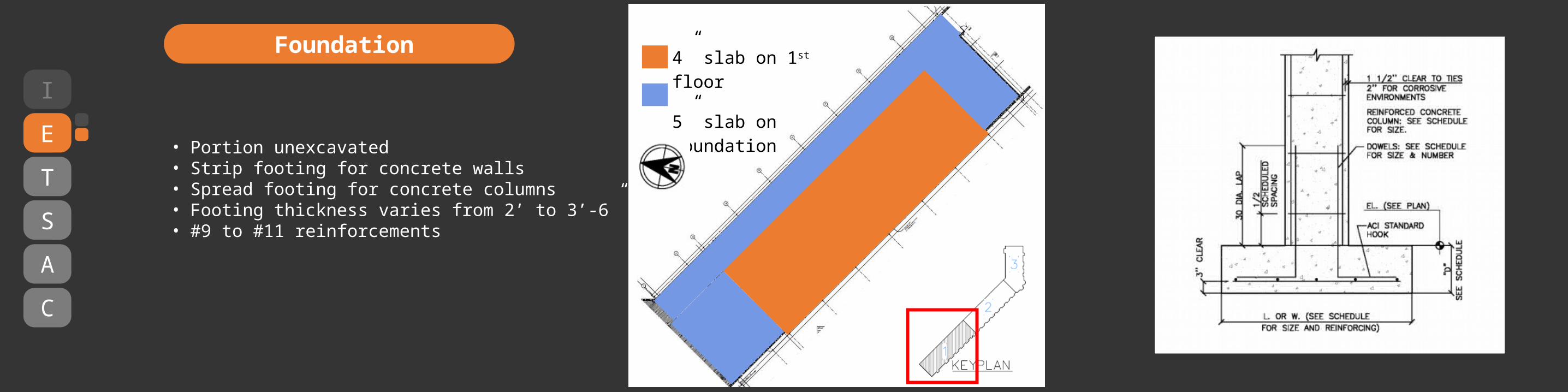
• Portion unexcavated• Strip footing for concrete walls• Spread footing for concrete columns• Footing thickness varies from 2’ to 3’-6” • #9 to #11 reinforcements
4” slab on 1st floor
5” slab on foundationI
E
T
S
A
C
Foundation

I
E
T
S
A
C
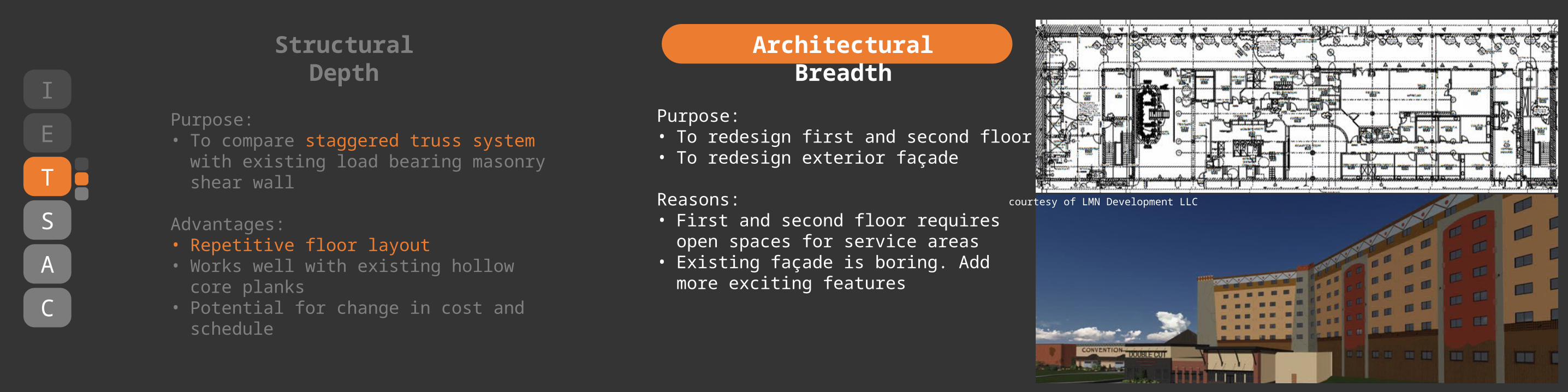
Structural Depth
Purpose: • To compare staggered truss system with
existing load bearing masonry shear wall
Advantages:• Repetitive floor layout• Works well with existing hollow core planks• Potential for change in cost and schedule
I
E
T
S
A
C
Structural Depth
Purpose: • To compare staggered truss system with
existing load bearing masonry shear wall
Advantages:• Repetitive floor layout• Works well with existing hollow core planks• Potential for change in cost and schedule
Architectural Breadth
Purpose: • To redesign first and second floor• To redesign exterior façade
Reasons:• First and second floor requires open spaces
for service areas• Existing façade is boring. Add more exciting
features
courtesy of LMN Development LLC
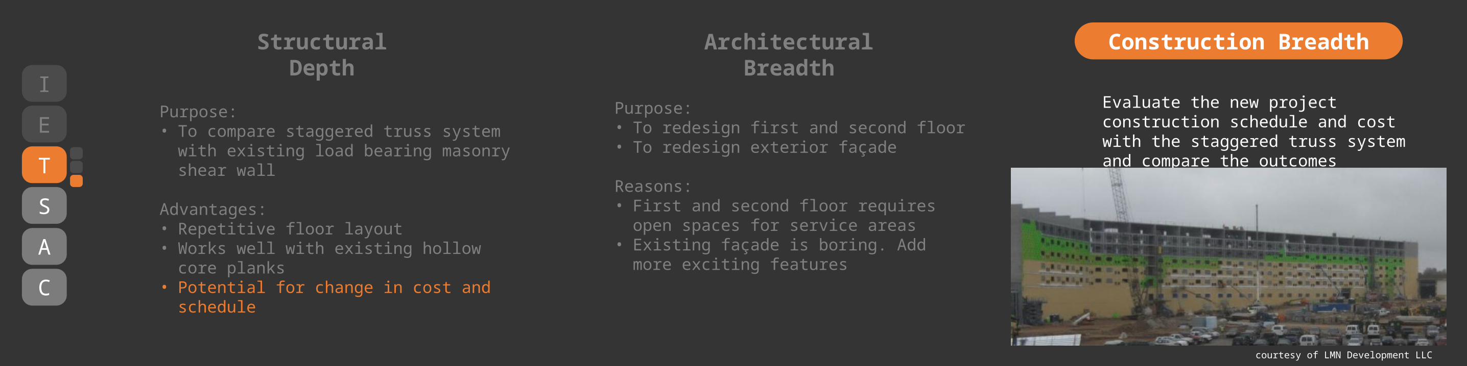
Evaluate the new project construction schedule and cost with the staggered truss system and compare the outcomes
I
E
T
S
A
C
Structural Depth
Purpose: • To compare staggered truss system with
existing load bearing masonry shear wall
Advantages:• Repetitive floor layout• Works well with existing hollow core planks• Potential for change in cost and schedule
Architectural Breadth Construction Breadth
Purpose: • To redesign first and second floor• To redesign exterior façade
Reasons:• First and second floor requires open spaces
for service areas• Existing façade is boring. Add more exciting
features
courtesy of LMN Development LLC
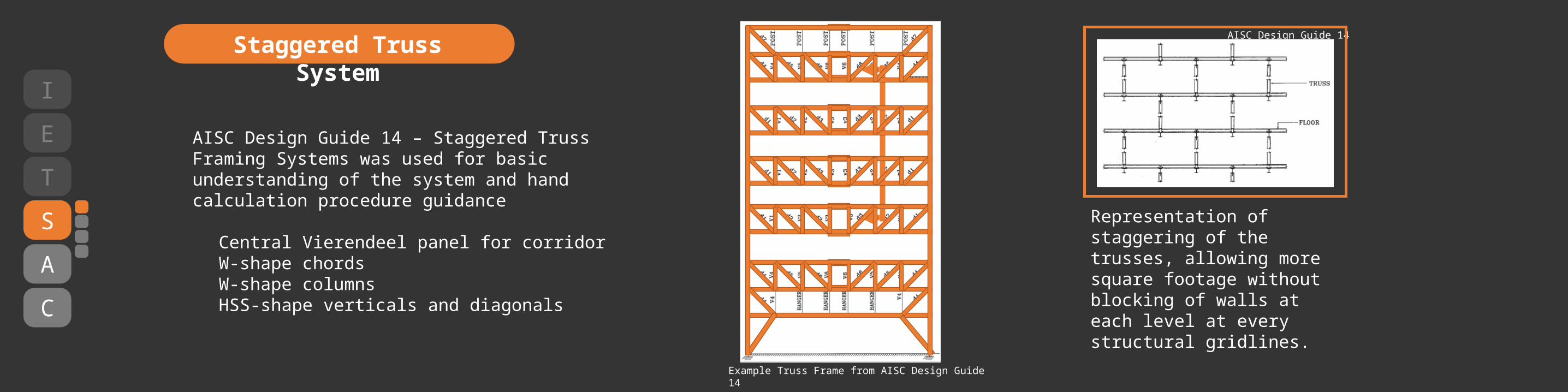
AISC Design Guide 14 – Staggered Truss Framing Systems was used for basic understanding of the system and hand calculation procedure guidance
Central Vierendeel panel for corridorW-shape chordsW-shape columnsHSS-shape verticals and diagonals
Representation of staggering of the trusses, allowing more square footage without blocking of walls at each level at every structural gridlines.
I
E
T
S
A
C
Staggered Truss System
Example Truss Frame from AISC Design Guide 14
AISC Design Guide 14

I
E
T
S
A
C
Staggered Truss System
Truss 1 Truss 2
Dead Load• 68 psf – hollow core planks• 37.5 psf – composite topping• 10 psf – super imposed load
Live Load• 40 psf – hotel rooms• 100 psf – corridor• 100 psf – lobby area
I
E
T
S
A
C
Staggered Truss System
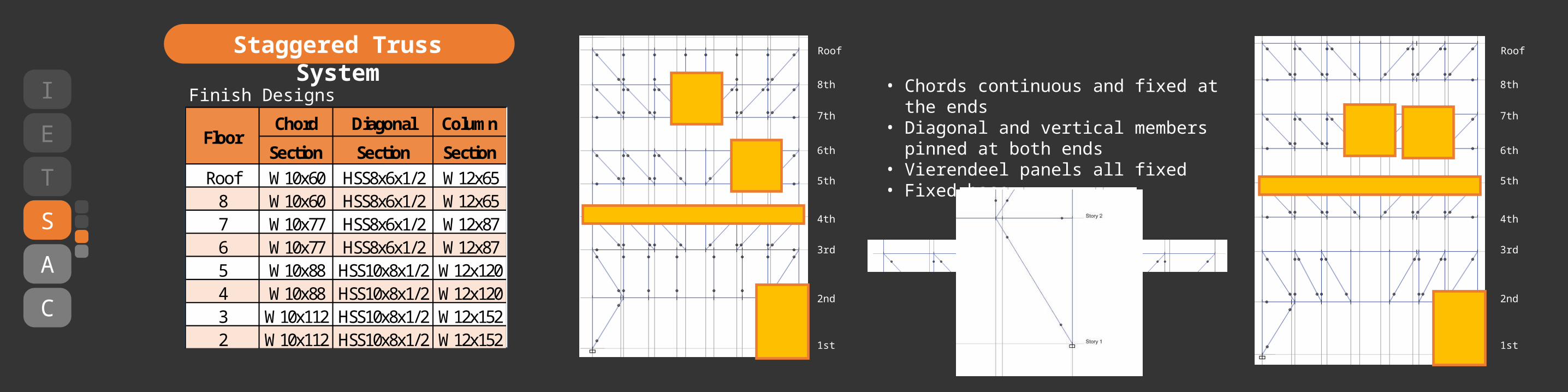
Chord Diagonal Column
Section Section SectionRoof W10x60 HSS8x6x1/2 W12x658 W10x60 HSS8x6x1/2 W12x657 W10x77 HSS8x6x1/2 W12x876 W10x77 HSS8x6x1/2 W12x875 W10x88 HSS10x8x1/2 W12x1204 W10x88 HSS10x8x1/2 W12x1203 W10x112 HSS10x8x1/2 W12x1522 W10x112 HSS10x8x1/2 W12x152
Floor
• Chords continuous and fixed at the ends• Diagonal and vertical members pinned at
both ends• Vierendeel panels all fixed• Fixed base
Finish Designs
Roof
8th
7th
6th
5th
4th
3rd
2nd
1st
Roof
8th
7th
6th
5th
4th
3rd
2nd
1st

Chord deflection• Largest deflection = 0.919” < L/240 = 3.35”• Largest LL deflection = 0.29” < L/360 = 2.23”
Column lateral deflection (wind)• Roof displacement = 0.526” < L/400 = 2.01”
I
E
T
S
A
C
Deflections
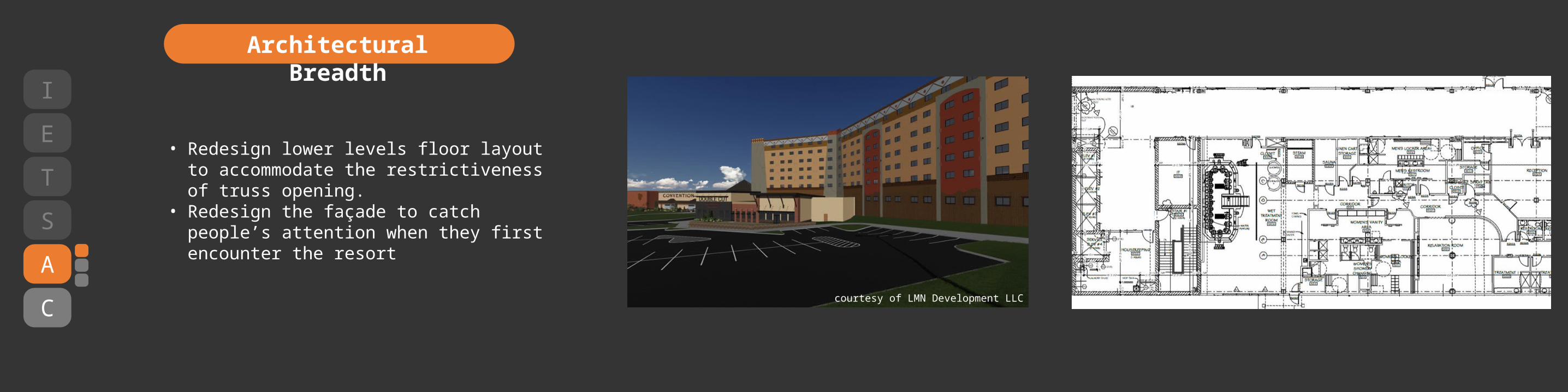
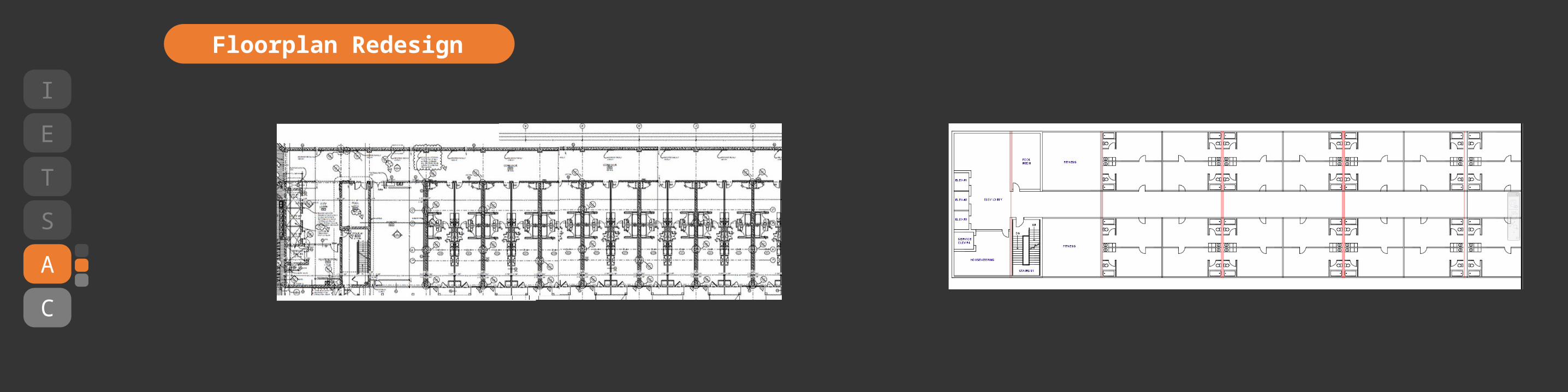
• Redesign lower levels floor layout to accommodate the restrictiveness of truss opening.
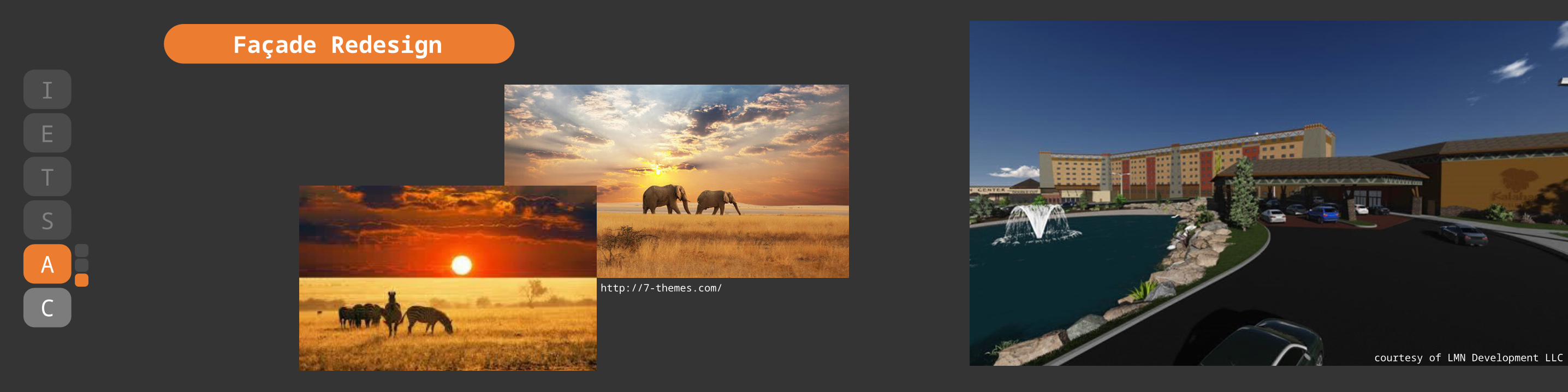
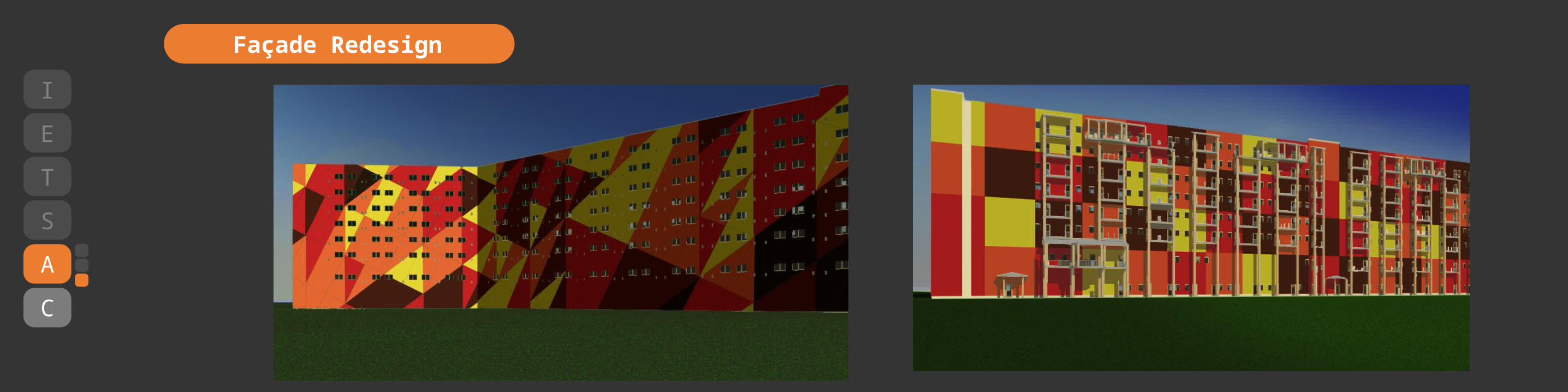
• Redesign the façade to catch people’s attention when they first encounter the resort
I
E
T
S
A
C
Architectural Breadth
courtesy of LMN Development LLC
I
E
T
S
A
C
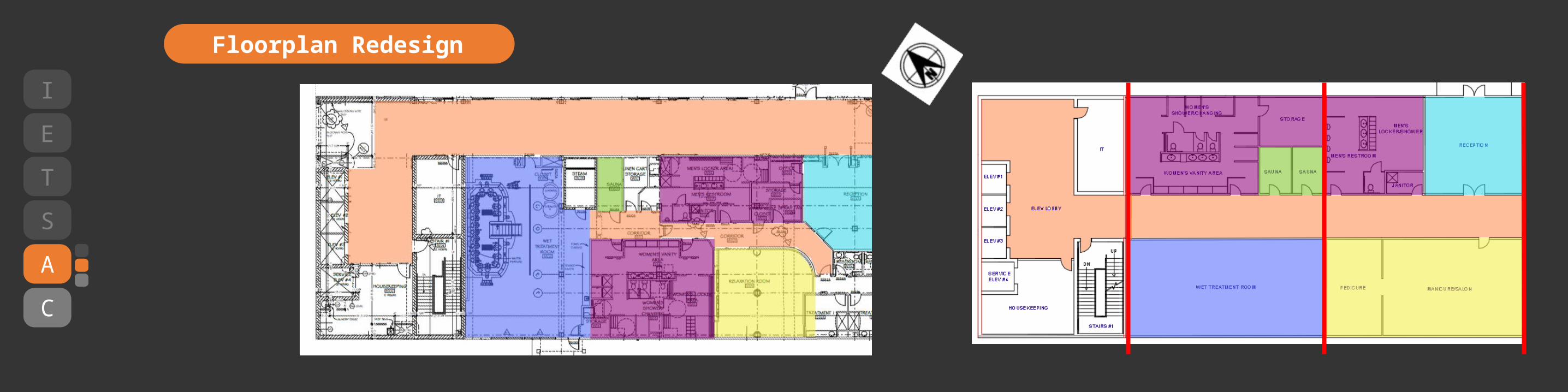
Floorplan Redesign
I
E
T
S
A
C
Floorplan Redesign
http://7-themes.com/
I
E
T
S
A
C
Façade Redesign
courtesy of LMN Development LLC
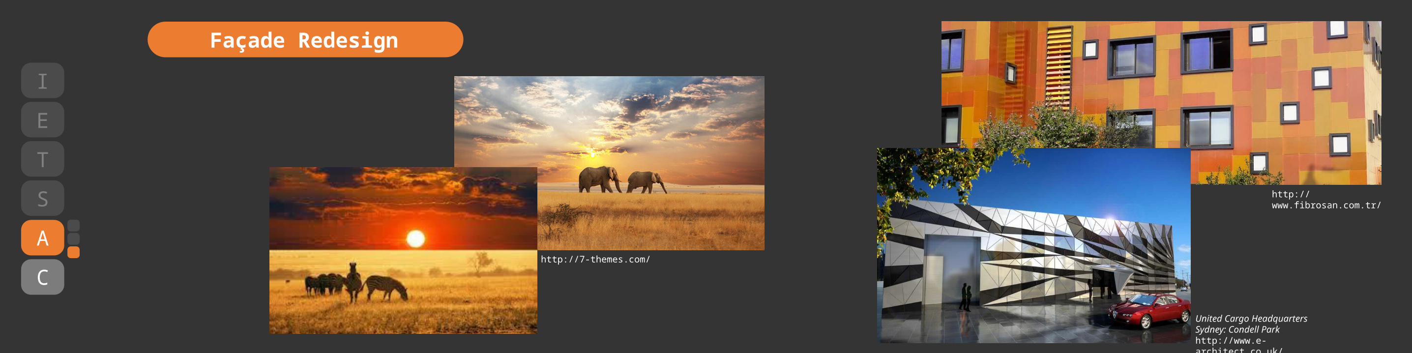
http://7-themes.com/
http://www.fibrosan.com.tr/
United Cargo Headquarters Sydney: Condell Parkhttp://www.e-architect.co.uk/
I
E
T
S
A
C
Façade Redesign
I
E
T
S
A
C
Façade Redesign
I
E
T
S
A
C
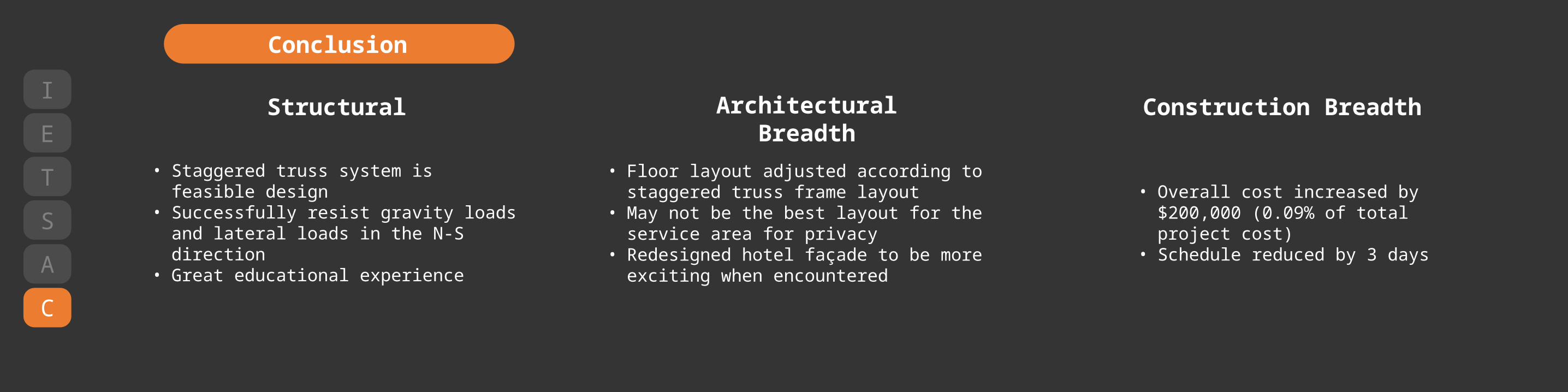
Conclusion
Structural
• Staggered truss system is feasible design• Successfully resist gravity loads and lateral
loads in the N-S direction• Great educational experience
Architectural Breadth Construction Breadth
• Floor layout adjusted according to staggered truss frame layout
• May not be the best layout for the service area for privacy
• Redesigned hotel façade to be more exciting when encountered
• Overall cost increased by $200,000 (0.09% of total project cost)
• Schedule reduced by 3 days

Special Thanks to…
LMN Development, LLC
All AE Structural Faculty membersEspecially Prof. Sustersic
My family and friends
Heavenly Father and His Son Jesus Christ
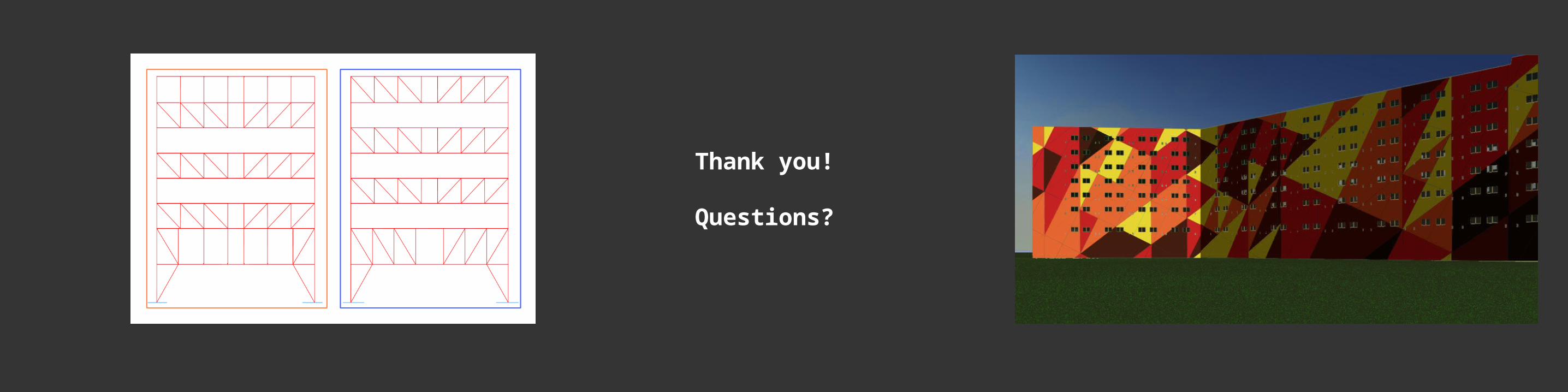
Thank you!
Questions?


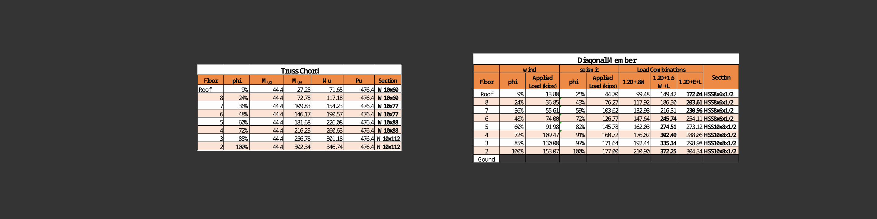
Floor phi Mug Muw Mu Pu SectionRoof 9% 44.4 27.25 71.65 476.4 W10x60
8 24% 44.4 72.78 117.18 476.4 W10x607 36% 44.4 109.83 154.23 476.4 W10x776 48% 44.4 146.17 190.57 476.4 W10x775 60% 44.4 181.68 226.08 476.4 W10x884 72% 44.4 216.23 260.63 476.4 W10x883 85% 44.4 256.78 301.18 476.4 W10x1122 100% 44.4 302.34 346.74 476.4 W10x112
Truss ChordFloor phi
Applied Load (kips)
phiApplied
Load (kips)1.2D+.8W
1.2D+1.6W+L
1.2D+E+L
Roof 9% 13.80 25% 44.70 99.48 149.42 172.04 HSS8x6x1/28 24% 36.85 43% 76.27 117.92 186.30 203.61 HSS8x6x1/27 36% 55.61 59% 103.62 132.93 216.31 230.96 HSS8x6x1/26 48% 74.00 72% 126.77 147.64 245.74 254.11 HSS8x6x1/25 60% 91.98 82% 145.78 162.03 274.51 273.12 HSS10x8x1/24 72% 109.47 91% 160.72 176.02 302.49 288.06 HSS10x8x1/23 85% 130.00 97% 171.64 192.44 335.34 298.98 HSS10x8x1/22 100% 153.07 100% 177.00 210.90 372.25 304.34 HSS10x8x1/2
Gound
Section
Diagonal MemberLoad Combinationswind seismic

Moment
Floor DL DL+RLL DL DL+RLL Pu Mu Pu MuRoof 207 264 16 207 264 16 55 289.8 77 351.032 66 W12x658 16 207 264 32 289.8 0 370.232 0 W12x657 207 264 16 414 528 48 65 579.6 91 721.2641 78 W12x876 16 414 528 64 579.6 0 740.4641 0 W12x875 207 264 16 621 792 80 77 869.4 107.8 1091.496 92.4 W12x1204 16 621 792 96 869.4 0 1110.696 0 W12x1203 207 264 16 828 1056 112 82 1159.2 114.8 1461.728 98.4 W12x1522 16 828 1056 128 1159.2 0 1480.928 0 W12x152
Gound 207 264 16 1035 1320 144 97 1449 135.8 1831.96 116.4
DL
Column 6AAxial Forcs
Ext Wallfloor total
Ext Wall
Load Combinations1.4D 1.2D+1.6L Section

Level 1.2D+L+1.6W 1.2D+L+ERoof 0.009 0.0178 0.014 0.0247 0.025 0.0326 0.027 0.0355 0.031 0.0344 0.043 0.0633 0.147 0.1152 0.23 0.1821 0 0
Total 0.526 0.502
Lateral Story Drifts (in)Chord Size
1.2D+1.6L 1.6L
W10x60 0.919 0.29W10x77 0.883 0.243W10x88 0.854 0.18W10x112 0.691 0.183
Gravity Deflections (in)
