an-724 ntb pes32nt24g2 - renesas
TRANSCRIPT

Notes
®
Application NoteAN-724
Non-transparent Bridging with IDT 89HPES32NT24G2 PCI Express® NTB Switch
By Kwok Kong
OverviewThis application note describes how a Non-transparent Bridge (NTB) may be used to connect two Root
Complexes. It describes the architecture of NTB, the enumeration process, transaction routing includingaddress and ID translations, interprocessor communication mechanism, error handling, and initializationprocedures. All descriptions and examples are based on the IDT 89HPES32NT24G2 device (referred tohereafter as PES32NT24G2).
IntroductionThere are three basic types of devices in a native PCI Express (PCIe®) system; Root Complexes, PCIe
switches, and Endpoints. There is only a single Root Complex in a PCIe tree. A Root Complex is a singleprocessor sub-system which includes a single PCIe port, one or more CPUs with associated RAM andmemory controller, and other inter-connect and/or bridging functions.
PCI Express routes are based on memory address or ID, depending on the transaction type. Thus,every device (or function within a device) must be uniquely identified within a PCI Express tree. Thisrequires a process called enumeration.
During system initialization, the Root Complex performs enumeration to determine the various busesthat exist and the devices that reside on each bus, as well as the required address space for the device’sregisters and memory. The Root Complex allocates bus numbers to all the PCIe Buses and configures thebus numbers to be used by the PCIe switches. A PCIe switch behaves as if it were multiple PCI-PCIBridges (see inset in Figure 1). The Root Complex allocates and configures the Memory and I/O addressspace for each PCIe Switch and Endpoint device. A PCIe tree topology is shown in Figure 1.
Figure 1 PCIe Tree Topology
UP: Upstream portDP: Downstream Port
Root Complex
PCIeSwitch
UP
DP
UP
DP
DPDPDPDP
PCIeSwitch
Endpoint
EndpointEndpointEndpointEndpoint
PCI-PCIBridge
PCI-PCIBridge
PCI-PCIBridge
VirtualPCI bus
1 of 27 September 30, 2009

IDT Application Note AN-724
Notes
In multi-Root systems, more than one processor sub-system exists within a PCI Express tree. Forexample, a second Root Complex may be added to the system via the Downstream Port (DP) of a PCIeswitch, possibly to act as a warm stand-by to the primary Root Complex. However, an issue arises when thesecond Root Complex also attempts the enumeration process. Assuming that the link trains (i.e., usingcrosslink training), it sends out Configuration Read Messages to discover other PCIe devices on thesystem. Configuration transactions can only move from Upstream to Downstream. A PCIe switch does notforward or respond to Configuration Messages that are received on its Downstream Port (DP); it ignoresand silently drops all the configuration messages. Thus, the second Root Complex is isolated from the restof the PCIe tree and will not detect any PCIe devices in the system. So, simply adding processors to aDownstream Port of a PCIe switch will not provide a multi-Root Complex solution.One method of supporting multiple Root Complexes in a PCIe system is to use an NTB to isolate theaddress domains of each of the Root Complexes. An NTB allows two Root Complexes or PCIe trees to beinterconnected with one or more shared address windows between them.
NTB in the PES32NT24G2An architectural block diagram of NTB in the PES32NT24G2 is shown in Figure 2 . NTB is implemented
as an NT function. An NT function may co-exist with an upstream switch port or exist as an NT function port(NTB port). Each NT function appears as a PCIe endpoint. There is a virtual NT interconnect within theswitch to allow communication among the NT functions. The NT interconnect is invisible to the PCIe hier-archy.
Figure 2 Architecture of NTB in PES32NT24G2
The PES32NT24G2 supports up to 8 NT functions. Figure 3 shows an example of a possible NTBconfiguration which has 4 partitions and 4 NT functions. The 4 NT functions are all connected via a virtualNT Interconnect to allow inter-domain communication. Two of the partitions represent two independentthree-port transparent PCIe switches. The upstream port of each partition is configured to operate as anupstream port with NT function. Two other partitions represent two NT endpoints and are configured tooperate as NTB ports. Another possible configuration is shown in Figure 4. In this configuration, 8 partitionsare created and the NT functions are configured to operate as NTB ports.
PCI-PCIBridge
Virtual PCI Bus
PCI-PCIBridge
NTB
NTB
NT Interconnect
2 of 27 September 30, 2009

IDT Application Note AN-724
Notes
Figure 3 Possible Configurations of NT Functions
Figure 4 NTB on All Ports
System ArchitectureThis section provides a few examples of a system topology using NTB to connect multiple Root
Complexes. The usage model of these topologies is to allow multiple Root Complexes to exchange datausing NTB with a PCIe interface. There are other usage models for NTB, such as a redundant RootComplex, but these are not covered in this application note.
An example of a system that uses a single PES32NT24G2 is shown in Figure 5. In this topology, thesecond root complex (CPU 2) is connected to the NTB port of the PES32NT24G2. Two address domainsare created: CPU 1 address domain and CPU 2 address domain. CPU 1 and 2 can exchange data via theNTB port. In fact, any endpoint in the CPU 1 address domain may exchange data with CPU 2 and viceversa.
PCI-PCIBridge NTB
PCI-PCIBridge
PCI-PCIBridge
PCI-PCIBridge NTB
PCI-PCIBridge
PCI-PCIBridge
Upstream Port with NT function
NTB
Downstream Ports NTB Ports
Upstream Port with NT function
PES32NT24G2
NTB
NT InterconnectVirtual PCI Bus Virtual
PCI Bus
NTBNTB NTB NTBNTB
NTB Ports
NTBNTBNTBNTB NTBNTB NTBNTB
PES32NT24G2NT Interconnect
3 of 27 September 30, 2009

IDT Application Note AN-724
Notes
Figure 5 System Topology with Two Root Complexes
A similar example of a system that has 3 NT functions configured is shown in Figure 5. In this topology,the third root complex (CPU 3) is connected to the another NTB port of the PES32NT24G2. A total of threeaddress domains are created: CPU 1, CPU 2, and CPU 3. CPU 1, CPU 2, and CPU 3 can exchange datavia the NT functions. The PES32NT24G2 supports up to 8 NT functions; thus, this topology can beextended to connect up to 8 Root Complexes using a single PES32NT24G2.
Figure 6 System Topology with Three Root Complexes
An example of a system that uses two PES32NT24G2s is shown in Figure 7. In this topology, the RootComplex CPU 1 sub-system is identical to the Root Complex CPU 2 sub-system. The two Root Complexesare connected to each other using two NTB ports. Three address domains are created: CPU 1 address
4 of 27 September 30, 2009

IDT Application Note AN-724
Notes
domain, CPU 2 address domain, and the NTB port address domain. This system works in a similar mannerto the system shown in Figure 5. CPU 1 and 2 can exchange data via the NTB ports, and any endpoint inthe CPU 1 address domain may exchange data with CPU 2 and vice versa.Figure 7 System Topology with NTB to NTB Connection
Transaction RoutingPCIe defines three transaction routing mechanisms:
◆ Address routing with 32-bit or 64-bit format◆ ID-based routing using bus, device, and function numbers◆ Implicit routing using messages
There are four transaction types defined by the PCIe standard: Memory Read/Write, I/O Read/Write,Configuration Read/Write, and Message. Memory Read, Memory Write, I/O Read, I/O Write transactionsare address-routed and are forwarded by the PES32NT24G2 across the NTB. Completions are ID-routedand are forwarded by the PES32NT24G2 across the NTB.
Configuration transactions and messages are not forwarded across the NTB. If a message is receivedby an NT function, it is silently discarded. If a Configuration transaction is received by an NTB endpoint, it isassumed that the configuration transaction is destined for the endpoint which receives it.
Address TranslationEach NT function contains six base address registers (BARs) in its Type 0 header. BARs can be
mapped into 32-bit memory address space. Odd and even numbered BARs may be paired to form 64-bitaddress windows. BAR0 can be configured to enable memory-mapped access to the configuration regis-ters in the NTB endpoint.
An NT function supports Direct Address Translation and Lookup Table Address Translation. All BARsmay be configured to support Direct Address Translation. BAR2 and BAR4 may be configured to supportLookup Table Translation. A memory address may be translated from 32-bit to 64-bit or from 64-bit to 32-bit.
Each BAR has a corresponding setup register (BARSETUP) and translated base register (BARLTBASEand BARUTBASE) in the NTB endpoint configuration capability structure. There is a lookup table that maybe used by BAR2 and BAR4 for Lookup Table Address Translation. The setup register contains fields thatconfigure the corresponding BAR, such as the type of BAR (Memory or I/O), the address window size,Direct or Lookup Table Address Translation, and the destination partition after translation. The format of thesetup register is shown in Figure 8. The translated base register contains the base address of the transac-
5 of 27 September 30, 2009

IDT Application Note AN-724
Notes
tions forwarded through the NT Interconnect using the corresponding BAR. The base address of a BARcorresponds to those address bits which are examined to determine if an address falls into a regionmapped to a BAR.Figure 8 BARSETUP Register Format
The Direct Address Translation logic is shown in Figure 9. It shows how the address is translated whena packet is forwarded from one NTB endpoint to another NTB endpoint. When a Transaction Layer Packet(TLP) is received by an NTB endpoint, the address field is extracted from the PCIe transaction layer packet.The address and type are compared against BAR0 through BAR6. If the address falls within the windowsize of one of the BARs, the base address of the original address is replaced with the content of the corre-sponding Translated Base Address Register. The original address offset is added to the translated addressbefore the packet is forwarded to the destination NTB endpoint (or partition). If the address does not find amatch in BAR0 to BAR6, the packet is dropped.
Figure 9 Direct Address Translation
The Lookup Table Address Translation logic is shown in Figure 10. BAR 2 or 4 may be configured tosupport Lookup Table Address Translation. BAR 2 may be configured to support either a 12-entry or 24-entry lookup table. BAR4 only supports a 12-entry lookup table. When both BAR 2 and 4 are configured to
31 30 17 16 13 12 11 10 9 4 3 2 1 0
0 0 0
Prefetchable: 1 = yes, 0 = no
Type: 00: 32 bit, 10: 64 bit
Memory space: 0 = memory, 1 = I/O
ReservedEN Size
Enable: 0 = disable, 1 = enable
TPART ATRAN
Translated Partition number: 0-7
Address Translation:
0: d irect address transla tion
1: 12-entry lookup table address translation
2: 24-entry lookup table address translation
BAR Mode: 0=address, 1=configuration space
+
Transaction Address
Base Address Offset
BAR Translated Base Address Register
Translated Address
6 of 27 September 30, 2009

IDT Application Note AN-724
Notes
support Lookup Table Address Translation, then BAR 2 only support a 12-entry lookup table. Each entry inthe look table contains the translated address and the destination partition number where the packet is tobe forwarded to.In a Lookup Table Address Translation, the address field is logically divided into the base address, indexand offset. The base address is to be used to compare the BAR registers. The index is used to specify oneof the entries in the lookup table, and offset is the offset address within a memory window. When a packet isreceived by an NTB endpoint, the address field is extracted from the PCIe transaction layer packet. Thebase address and type are compared against BAR0 through BAR6. If the address falls within the windowsize of either BAR 2 or BAR 4, the base address and the index of the original address is replaced with thecontent of the corresponding lookup table entry (which contains the translated base address) as pointed toby the index. The original address offset is added to the translated address before the packet is forwardedto the destination NTB endpoint (or partition) as specified in the lookup table entry.
Figure 10 Lookup Table Translation
Address Translation ExamplesA topology example of how address translation works is shown in Figure 11. In this example, three NT
functions are enabled. The Root Complex (RC) connects to NTB 0 (partition 0), EP1 connects to the NTB 1(partition 1) port, and EP2 connects to the NTB 2 (partition 2) port. Each Root Complex, EP1, and EP2creates an outbound address window to access the memory address space of each other. Each one ofthem creates two inbound address windows to allow the others to access its local memory. It has a dedi-cated inbound address window for each of the other two NTB endpoints.
0
1
1011
Translated Base AddressTranslated Base Address
Translated Base AddressTranslated Base Address
...+
Base Address Index Offset
BAR2 (or 4)
Translated Address
Transaction Address
7 of 27 September 30, 2009

IDT Application Note AN-724
Notes
Figure 11 Address Translation Example Topology
The memory map of Address Windows is shown in Figure 12. In the example, EP1 is configured to useDirect Address Translation. The Root Complex and EP2 are configured to use Lookup Table AddressTranslation. Each RC, EP1, and EP2 allocates two local memory regions as the Inbound Address Windows.The size of each local memory window is 1 MByte. Each of the 1 MByte memory is to be mapped to theOutbound Address Window of the other two NTB endpoints. In this example, the Root Complex’s localaddress window at 0x1000 0000 is mapped to one of the EP1’s outbound address window and the localaddress window at 0x1040 0000 is mapped to one of the EP2’s outbound address window. The RC andEP2 use Lookup Table Address Translation, one outbound address window is needed for each one of them.The outbound address window is then sub-divided into two memory windows to map to the other two NTBendpoints. EP2 uses direct address translation, and two outbound address windows are created in order tomap the windows to RC and EP2’s address space.
OAW: Outbound Address WindowIAW: Inbound Address Window
NTB0
NTB2
NTB1
Root Complexx86
CPUM emoryMem ory
I/O Hub
EP 1
x8 6CPU
Mem oryMem
I/O Hub
EP 1
x8 6CPU
Mem oryMem
I/O Hub
EP 2
x86CP U
M em oryM em
I/O Hub
EP 2
x86CP U
M em oryM em
I/O Hub
O AW: 0 xE000 0000IA W : 0 x1000 0000 (for EP1)
0x104 0 000 0 (for EP2 )
O A W : 0xE100 0000IAW : 0x1100 000 0 (for RC)
0x 1108 0000 (for EP2)
O AW : 0xE200 0000IAW : 0x180 0 000 0 (for RC)
0x 1850 0000 (for EP1)
PCI-PCIBridge
PCI-PCIBridge
PCI-PCIBridge
8 of 27 September 30, 2009

IDT Application Note AN-724
Notes
Figure 12 Memory Maps
The lookup table configuration for NTB0 is shown in Figure 13. BAR 2 is configured to use Lookup TableAddress Translation with 12-entry. The size of BAR2 is 16 MBytes such that each entry represents 1 MByteof memory size. Only two entries are enabled in the lookup table. Entry 0 is configured to translate theaddress to 0x1100 0000 and the packet is to be forwarded to NTB 1 (partition 1) after address translation.Entry 1 is configured to translate the address to 0x1800 0000 and the packet is to be forwarded to NTB 2after address translation.
Figure 13 NTB0 Address Translation Configuration
0x0000 0000
0x1000 0000
0x1010 0000
0xFFFF FFFF
LocalDRAM
InboundWindow
OutboundWindow
0xE000 0000
0xE100 0000
16 MB
1 MB
RC Memory Map(Lo okup Table Translation)
0x0000 0000
0x1100 0000
0x1120 0000
0xFFFF FFFF
LocalDRAM
InboundWindow
0xE100 0000
0xE120 0000
2 MB
1 MB
EP1 Mem ory Map(Direct Add ress Transla tion)
0x0000 0000
0x1800 0000
0x1810 0000
0xFFFF FFFF
LocalDRAM
InboundWindow
OutboundWindow
0xE200 0000
0xE300 0000
16 MB
1 MB
EP2 Mem ory Map(Lo okup Table Translation)
OutboundWindows
InboundWindow
0x1040 0000
0x1050 00001 MB
InboundWindow
InboundWindow
0x1108 0000
0x1190 0000
0x1850 0000
0x1860 00001 MB1 MB
NTB0
NTB2
NTB1
Root Complexx86
CPUM emoryMem ory
I/O Hub
EP 1
x8 6CPU
Mem oryMem
I/O Hub
EP 1
x8 6CPU
Mem oryMem
I/O Hub
EP 2
x86CP U
M em or yM em
I/ O Hub
EP 2
x86CP U
M em or yM em
I/ O Hub
O A W: 0 xE000 0000IAW : 0 x1000 0000 (for EP1)
0x104 0 000 0 (for EP2 )
O AW : 0xE100 0000IAW : 0x1100 000 0 (for RC )
0x 1108 0000 (for EP2)
O A W : 0xE200 0000IAW : 0x180 0 000 0 (for RC)
0x 1850 0000 (for EP1)
PCI-PCIBridge
PCI-PCIBridge
PCI-PCIBridge
--011
……
--02
0x1800 0000211
0x1100 0000110
Translated Address
PartitionValidIndex
--011
……
--02
0x1800 0000211
0x1100 0000110
Translated Address
PartitionValidIndex
NTB0 Lookup Table
9 of 27 September 30, 2009

IDT Application Note AN-724
Notes
The NTB0 address translation logic is shown in Figure 14. When a TLP is sent by the Root Complex toEP1, the address must be in the range of 0xE000 0000 to 0xE00F FFFF. The Base address is extractedfrom the TLP and compared to BAR 0 to 5. The base address (0xE0000 0000) matches BAR2 and theindex (0) is used to access the lookup table. The TLP is forwarded to NTB 1 (partition 1) and the address istranslated to have the base address of 0x1100 0000. The offset is then added to the translated addressbefore the TLP is forwarded to EP1. When a TLP is sent by the Root Complex to EP2, the address must bein the range of 0xE010 0000 to 0xE01F FFFF. This has an index of 1 and the TLP is forwarded to NTB 2(partition 2) and the address is translated to have a base address of 0x1800 0000. The offset is then addedto the translated address before the TLP is forwarded to EP2.EP2 is configured to use Lookup Table Address Translation and the address translation works identicallywith the Root Complex address translation.
.
Figure 14 NTB0 Address Translation Logic Example
NTB1 is configured to use direct address translation. A BAR is required to map the outbound addresswindows to another partition (i.e. NTB). It opens an address window to NTB 0 and a second addresswindow to NTB 2. The address translation configuration is shown in Figure 15. BAR 1 is configured to havea size of 1 Mbyte, destination partition 0 (NTB 0), and the translated base address of 0x1000 0000. Thisoutbound address window is used to access the local memory of the Root Complex. BAR 2 is configured tohave a size of 1 Mbyte, destination partition 2 (NTB 2), and the translated base address of 0x1850 0000.This outbound address window is used to access the local memory of EP2.
01
1012
...
+
Base Address Index Offset
0xE000 0000
Translated Address To EP1
Transaction Address From Root Complex
12
0x1100 00000x1800 0000
--
0xE000 0000 - 0XE00F FFFF
0X1100 0000 - 0X110F FFFF
BAR2
10 of 27 September 30, 2009
IDT Application Note AN-724
Notes
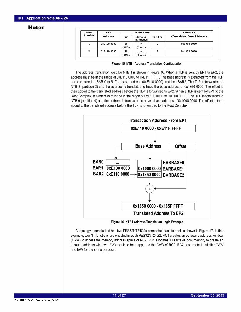
Figure 15 NTB1 Address Translation Configuration
The address translation logic for NTB 1 is shown in Figure 16. When a TLP is sent by EP1 to EP2, theaddress must be in the range of 0xE110 0000 to 0xE11F FFFF. The base address is extracted from the TLPand compared to BAR 0 to 5. The base address (0xE110 0000) matches BAR2. The TLP is forwarded toNTB 2 (partition 2) and the address is translated to have the base address of 0x1850 0000. The offset isthen added to the translated address before the TLP is forwarded to EP2. When a TLP is sent by EP1 to theRoot Complex, the address must be in the range of 0xE100 0000 to 0xE10F FFFF. The TLP is forwarded toNTB 0 (partition 0) and the address is translated to have a base address of 0x1000 0000. The offset is thenadded to the translated address before the TLP is forwarded to the Root Complex.
Figure 16 NTB1 Address Translation Logic Example
A topology example that has two PES32NT24G2s connected back to back is shown in Figure 17. In thisexample, two NT functions are enabled in each PES32NT24G2. RC1 creates an outbound address window(OAW) to access the memory address space of RC2. RC1 allocates 1 MByte of local memory to create aninbound address window (IAW) that is to be mapped to the OAW of RC2. RC2 has created a similar OAWand IAW for the same purpose.
0x1850 000020
(D irect)
20
(1MB)
0xE110 00002
0x1000 000000(D irect)
20(1MB)
0xE100 00001
PartitionAddress Translation
Size
BARB ASE(Translated B ase Address )
BA RSETUPBARA ddress
BAR Number
0x1850 000020
(D irect)
20
(1MB)
0xE110 00002
0x1000 000000(D irect)
20(1MB)
0xE100 00001
PartitionAddress Translation
Size
BARB ASE(Translated B ase Address )
BA RSETUPBARA ddress
BAR Number
+
Transaction Address From EP1
Base Address Offset
Translated Address To EP2
0xE110 0000 - 0xE11F FFFF
0xE100 00000xE110 0000
_0x1000 00000x1850 0000
_BAR0BAR1BAR2
0x1850 0000 - 0x185F FFFF
BARBASE0BARBASE1BARBASE2
11 of 27 September 30, 2009

IDT Application Note AN-724
Notes
Figure 17 Topology Example with two PES32NT24G2s
There is no Root Complex in the NTB 1 domain. RC1 uses the punch-through feature (see sectionPunch-Through on page 1-22 for a definition) to configure SW2 NTB1 during initialization. RC1 sendsconfiguration request to configure the BARs of SW2 NTB1. RC2 uses the punch-through feature toconfigure SW1 NTB1 during initialization. The BAR configuration for SW1 and SW2 is shown in Figure 18after initial initialization. RC1 configures NTB1 BAR0 of SW2 to have a value of 0x0000 0000 such that RC1can access all the registers of SW2 NTB1 using memory read and write operation instead of using punch-through to send configuration requests. It also configures SW2 NTB1 BAR2 to have a value of 0x0200 0000to open an inbound address window into RC2’s local memory. RC2 does the same configuration to SW1NTB1.
Figure 18 SW1 and SW2 BAR Configuration
The lookup table configuration is shown in Figure 19. SW1 NTB0 BAR2 is configured to have twoentries. The entry at index 0 contains the translated address to access the registers of SW2 NTB1. Theentry at index 1 contains the translated address to access the local memory of RC2. SW1 NTB1 BAR2contains a single entry to allow RC2 to access RC1’s local memory. SW2 is configured similarly.
P2P
P 2P P2P
NTB 0 P2P
P 2P
PE S32NT24G 2 PES 32NT24G2
RC 1x86
CP UM emoryM emory
I/O Hub
RC 2x86
CP UMemoryM emory
I /O Hub
P 2PNTB 1
NTB 0
NTB 1
OAW : 0xE00 0 00 00IAW: 0x11 00 00 00
OAW : 0xE000 0000IAW : 0x1000 000 0
SW 2SW 1
S W 1
0 x 0 2 0 0 0 0 0 0N T B 1 B A R 2
0 x 0 0 0 0 0 0 0 0N T B 1 B A R 0
0 x E 0 0 0 0 0 0 0N T B 0 B A R 2
A d d r e s sB A R
S W 1
0 x 0 2 0 0 0 0 0 0N T B 1 B A R 2
0 x 0 0 0 0 0 0 0 0N T B 1 B A R 0
0 x E 0 0 0 0 0 0 0N T B 0 B A R 2
A d d r e s sB A R
S W 2
0 x 0 2 0 0 0 0 0 0N T B 1 B A R 2
0 x 0 0 0 0 0 0 0 0N T B 1 B A R 0
0 x E 0 0 0 0 0 0 0N T B 0 B A R 2
A d d r e s sB A R
S W 2
0 x 0 2 0 0 0 0 0 0N T B 1 B A R 2
0 x 0 0 0 0 0 0 0 0N T B 1 B A R 0
0 x E 0 0 0 0 0 0 0N T B 0 B A R 2
A d d r e s sB A R
12 of 27 September 30, 2009

IDT Application Note AN-724
Notes
Figure 19 SW1 and SW2 Lookup Table Configuration
The SW1 and SW2 address translation logic is shown in Figure 20. When a TLP is sent by RC1 to RC2,the address must be in the range of 0xE010 0000 to 0xE01F FFFF. The base address is extracted from theTLP and compared to BAR 0 to 5. The base address (0xE000 0000) matches BAR2. The address has anindex of 1 in the lookup table. The TLP is forwarded to NTB 1 (partition 1) and the address is translated tohave the base address of 0x0200 0000. The offset is then added to the translated address before the TLPis forwarded. When SW2 receives the TLP, the base address is extracted and compared to BAR 0 to 5.The base address (0x0200 0000) matches BAR2. The address has an index of 0 in the lookup table. TheTLP is forwarded to RC2 and the address is translated to have the base address of 0x1100 0000. The offsetis then added to the translated address before the TLP is forwarded.
RC1 can access the registers of SW2 NTB1 using the address between 0xE000 0000 and 0xE0000FFF. The base address (0xE000 0000) matches BAR2. The address has an index of 0 in the lookup table.The TLP is forwarded to NTB1 and the address is translated to have the base address of 0x0000 0000. Theoffset is then added to the translated address before the TLP is forwarded. When SW2 receives the TLP,the base address is compared to BAR 0 to 5. The base address (0x0000 0000) matches BAR0 and the TLPis used to access the registers of SW2 NTB1.
RC2 works in a similar way to access the local memory of RC1 and the registers of SW1 NTB1.
--011
……
0x1000 0000010
T ra nsla te d A dd re ss
Pa rtitio nV a lidIn dex
--011
……
0x1000 0000010
T ra nsla te d A dd re ss
Pa rtitio nV a lidIn dex
0 x02 00 0000111
--011
……
0 x00 00 0000110
T rans late d A dd res s
Pa rtitio nVa lidInde x
0 x02 00 0000111
--011
……
0 x00 00 0000110
T rans late d A dd res s
Pa rtitio nVa lidInde x
0 x0200 0000111
--011
……
0x0000 0000110
Tra nsla te d A dd re ss
Pa rtitio nV a lidInde x
0 x0200 0000111
--011
……
0x0000 0000110
Tra nsla te d A dd re ss
Pa rtitio nV a lidInde x
S W 1 N T B0 B AR 2 L o ok u p Ta b le
--011
……
0 x11 00 0000010
T rans late d A dd res s
Pa rt itio nV alidInde x
--011
……
0 x11 00 0000010
T rans late d A dd res s
Pa rt itio nV alidInde x
S W 2 NT B 0 B A R 2 Lo o k up T a ble
SW 1 N TB 1 B A R 2 L oo k up T a ble S W 2 N T B 1 B AR 2 L o ok u p Ta b le
13 of 27 September 30, 2009

IDT Application Note AN-724
Notes
Figure 20 SW1 and SW2 Address Translation Logic
ID Routing and TranslationAssociated with the PES32NT24G2 is a 64-entry NT mapping table. The NT mapping table is used to
perform ID translation. The ID is the bus, device, and function number of a PCIe function. The NT mappingtable is a global table shared by all NT functions. The format of the NT mapping table is shown in Figure 21and the description of each field in the table is shown in Table 1. For the purpose of ID translation, only theValid, Function, Device, Bus and Partition are described here. Please refer to the PES32NT24G2 usermanual for details of the other fields.
B ase Ad d r ess O ffse tN T B 0 B A R 2
+
T ran s la te d Ad d re ss
T ra n sa c tio n A d d re ss F r o m R C 1
In d ex
-
…
0 x0 0 0 0 0 0 0 001..
11
1
0xE 010 00 00 – 0xE 01F F F F F
Bas e Ad d r ess O ffse tIn d ex
-
…
0 x1 1 0 0 0 0 0 00..
11
0
N T B 1 B AR 2
+
T r an s la te d Ad d r e ss to R C 2
0x 1100 00 00 – 0x1 10F FFF F
SW 1
S W 2
0 xE0 00 00 00
0x02 00 00 00
0 x0 20 0 00 0 01
14 of 27 September 30, 2009

IDT Application Note AN-724
Notes
Figure 21 NT Mapping Table Format
The NT mapping table contains the partition number, bus, device, and function (BDF) numbers of theinitiators on that side of the endpoint whose transactions may be forwarded to the NT Interconnect toanother partition. The V field indicates if the entry is Valid or not. The mapping table is filled in during systeminitialization. There is a single NT mapping table and is shared by all ports configured for NT operation.
Request ID TranslationWhen a request TLP is received by an NT endpoint that is to be routed on the NT interconnect, a
requester ID lookup and translation operation is performed. The lookup is performed by matching the 16-bitrequester ID in the request TLP along with the partition associated with the NT endpoint to entries in the NTMapping table. The partition number and the requester ID are compared to each of the valid entries in theNT mapping table. When there is a match, the requester ID is translated as shown in Figure 22. The busfield is replaced by the captured bus number of the NT endpoint associated with the partition of the trans-
Bit Field Field Name Description
0 V Valid. This bit is set if the mapping table is valid.
3:1 FUNC Function. This field contains the mapping table entry PCI Express function number.
8:4 DEV Device. This field contains the mapping table entry PCI Express device number.
16:9 BUS Bus. This field contains the mapping table entry PCI Express bus number.
19:17 PART Partition. This field contains the mapping table entry partition number.
29 ATP Address Type Processing. This field specifies the processing of the address type (AT) field on request TLPs.
30 CNS Completion No Snoop Processing. This field specifies the no snoop processing on completion TLPs.
31 RNS Request No Snoop Processing. This field specifies the no snoop processing on request TLPs.
Table 1 NT Mapping Table Field Description
V
Mapping TableEntry
FUNCDEVBUSPARTReserved01 VFUNCDEVBUSPARTReserved
VFUNCDEVBUSPARTReserved23 VFUNCDEVBUSPARTReserved
VFUNCDEVBUSPARTReserved45 VFUNCDEVBUSPARTReserved
VFUNCDEVBUSPARTReserved63
...
CNSRNSCNSRNSCNSRNSCNSRNSCNSRNSCNSRNS
CNSRNS
ATPATPATPATPATPATP
ATP
15 of 27 September 30, 2009

IDT Application Note AN-724
Notes
lated TLP. Bit 4 of the device field is set to one and Bit 3 of the device field is set to zero. The lower threebits of the device field and all three bits of the function field are replaced with the mapping table match entrynumber.Figure 22 Request TLP Requester ID Translation
Completion ID TranslationWhen a completion TLP is received by an NT endpoint, the request ID lookup and completion ID trans-
lation is performed. The Requester ID must be in the valid range (i.e. Bit 7 and 6 of the Request ID must be“10”) before a ID lookup is performed.
The lower 8-bit value of the Requester ID that consists of the device and function fields is extracted fromthe requester ID field. The top two bits are not used and the lower six bits form an NT Mapping table entryindex. If the NT mapping table entry index points to a valid entry in the NT mapping table, the completionTLP is forwarded to the partition as specified in the NT mapping table. Before the TLP is forwarded, boththe requester ID and the completer ID are translated as follows:
◆ The requester ID Bus, Device, and Function fields are replaced by the NT mapping table Bus, Device, Function fields.
◆ The completer ID of the translated completion TLP is equal to the Bus, Device, and Function of the NT endpoint associated with the partition of the translated completion TLP (i.e., the NT function that emits the TLP).
Requester ID Capture RegisterIn order to program the NT mapping table, the requester IDs of initiators in the PCI Express hierarchy
must be known. Typically, at least the ID of the Root Complex is added to the NT mapping table. The ID ofthe Root Complex is system dependent.
To facilitate programming of the NT mapping table, the Requester ID Capture register (REQIDCAP) maybe used to discover the ID of an initiator. When an initiator issues a configuration read request to theREQIDCAP register, a completion is generated that contains the ID of the initiator that issued the configura-tion read request.
Requester ID Translation ExampleAn example of an ID translation in shown in Figure 23. In this example, there is a single PES32NT24G2
with 3 NT functions enabled. The IDs of the Root Complex, EP1 and EP2 have the same value of 0.1.0. TheIDs of NTB0, NTB1 and NTB2 are 1.0.1, 1.0.0 and 2.0.0 respectively. There are three initiators orrequesters in the system. The IDs of the Root Complex, EP1 and EP2 are added to entry 0, 1, and 2 of theNT mapping table respectively.
B u s D e v i c e F u n c t io n
D e s t in a ti o n N T B C a p t u re d B u s M a tc h M a p p i n g T a b l e In d e x1
1 5 8 7 3 2 0
1 5 8 7 6 0
R e q u e s t T L P R e q u e s te r I D
T ra n s la te d R e q u e s te r I D
R e q u e s te r ID T ra n s la t io n
0
16 of 27 September 30, 2009

IDT Application Note AN-724
Notes
Figure 23 Requester ID Translation Example Topology
An example of the requester ID translation logic is shown in Figure 24. Root Complex performs amemory read request to EP1’s local memory. When the request TLP is received by NTB 0, the TLP isrouted by address to the destination NTB 1 as described in Address Translation. The address is translatedbefore the TLP is forwarded. In addition to the address translation, the Requester ID has to be translated aswell. The partition (0) and requester ID (BDF = 0.1.0) of the Root Complex are used to look up in the NTmapping table. A match is found and the matching entry has an index of 0. The requester ID is thenreplaced with the bus number of NTB 1 (1) and part of the device and function numbers are replaced withthe matching NT mapping table index of 0. The forwarded packet has a requester ID of 1.16.0.
A corresponding completion packet is received by NTB 1 some time later. The requester ID andcompleter ID of the completion packet are 1.16.0 (Requester ID of the corresponding request packet) and0.1.0 (EP1) respectively. Part of the device and function numbers of the Requester ID (0) are used as anindex to the NT mapping Table. The BDF of the NT mapping table entry at index 0 (0.1.0) and the BDF ofthe NTB 0 (1.0.1) are used to replace the Requester and Completer ID in the completion packet respec-tively. The translated packet is forwarded to partition 0 as indicated in entry 0 of the NT mapping table.
NTB0
NTB2
NTB1
Root Complexx86CPU
MemoryMemory
I/O Hub
EP 1
x86CPU
MemoryMem
I/O Hub
EP 1
x86CPU
MemoryMem
I/O Hub
EP 2
x86CPU
MemoryMem
I/O Hub
EP 2
x86CPU
MemoryMem
I/O Hub
PCI-PCIBridge
PCI-PCIBridge
BDF = 0.1.0 BDF = 0.1.0
BDF = 0.1.0
BDF = 1.0.1
BDF = 1.0.0
PCI-PCIBridge
BDF = 2.0.00.1.022
0.1.011
0.1.000
BDFPartitionIndex
0.1.022
0.1.011
0.1.000
BDFPartitionIndex
Mapping Table Setup
17 of 27 September 30, 2009

IDT Application Note AN-724
Notes
Figure 24 Requester ID Translation Logic
The ID translation works similarly when two NT ports are connected back-to-back as shown in Figure25. During initialization, RC1 configures the BDF of SW2 NTB1 to be 0.16.0 using punch-through. RC2configures the BDF of SW1 NTB1 to be 0.16.0 using punch-through. The SW1 and SW2 NT mappingtables are initialized as shown in Figure 25.
NTB 0
BDF = 1,0,1
NTB 1
BDF = 1.0,0
addr BDF0
12
0 0.1.01 0.1.02 0.1.0
Requester ID=1,16,0Completer ID = 0.1.0
Completion
Completion
index P BDF
0
12
0 0.1.0
2 0.1.0
Requester ID = 0,1,0
Mapping Table
Translated Requester ID = 1.16.0
Request
Request
(EP1)
Mapping Table
Lookup BDF
Requester ID = 0,1,0Completer ID = 1.0.1(NTB 0)
Root Complex (BDF = 0, 1, 0)
EP1 (BDF =0, 1, 0)
1 0.1.0Partition = 0
Partition = 1
P
18 of 27 September 30, 2009

IDT Application Note AN-724
Notes
Figure 25 Requester ID Translation Example with Back to Back NTB ports
An example of the requester ID translation logic with back-to-back NTB ports is shown in Figure 24. RC1performs a memory read request to RC2’s local memory. When the request TLP is received by SW1 NTB0,the TLP is routed by address to the destination SW1 NTB1 as described in Address Translation. Theaddress is translated before the TLP is forwarded. In addition to the address translation, the Requester IDhas to be translated as well. The partition (0) and requester ID (BDF = 0.1.0) of RC1 are used to look up inthe SW1 NT mapping table. A match is found and the matching entry has an index of 0. The requester ID isthen replaced with the bus number of NTB1 (0), and part of the device and function numbers are replacedwith the matching NT mapping table index of 0. The forwarded packet has a requester ID of 0.16.0.
When SW2 NTB1 receives the request TLP, the TLP is routed by address to the destination SW1 NTB0towards RC2. The address and Requester ID are translated. The partition (1) and requester ID (BDF =0.16.0) are used to look up in the SW2 NT mapping table. A match is found and the matching entry has anindex of 1. The requester ID is then replaced with the bus number of NTB0 (1), and part of the device andfunction numbers are replaced with the matching NT mapping table index of 1. The forwarded packet has arequester ID of 1.16.1.
A corresponding completion packet is received by SW2 NTB0 some time later. The requester ID andcompleter ID of the completion packet are 1.16.1 (Requester ID of the corresponding request packet) and0.1.0 (RC1) respectively. Part of the device and function numbers of the Requester ID (1) are used as anindex to the SW2 NT mapping table. The BDF of the NT mapping table entry at index 1 (0.16.0) and theBDF of the SW2 NTB1 (0.16.0) are used to replace the Requester and Completer ID in the completionpacket respectively. The translated packet is forwarded to partition 1 as indicated in entry 1 of SW2 NTmapping table.
The translated completion packet is received by SW1 NTB1. Both the requester ID and completer ID ofthe completion packet are 0.16.0. Part of the device and function numbers of the Requester ID (0) are usedas an index to the SW1 NT mapping Table. The BDF of the NT mapping table entry at index 0 (0.1.0) andthe BDF of SW1 NTB0 (1.0.1) are used to replace the Requester and Completer ID in the completionpacket respectively. The translated packet is forwarded to partition 0 towards RC1 as indicated in entry 0 ofthe NT mapping table.
P2P
P 2P P2P
NTB 0 P2P
P 2P
PES 32NT24G2
RC 1x86
CP UMem oryM em ory
RC 2x86
CP UMemoryM emory
P2PNTB 1
NTB 0
NTB 1
SW 2SW 1
PE S32NT24G 2
BDF = 0.1.0 BDF = 0.1.0
BDF = 0.16.0 BDF = 0 .16.0
BDF = 1.0.1 BDF = 1.0 .1
0.16.011
0.1.000
BDFPartit ionIndex
0.16.011
0.1.000
BDFPartit ionIndex
SW1 M apping Table Se tup
I/O HubI /O Hub
0.16.011
0.1.000
BDFPartitionIndex
0.16.011
0.1.000
BDFPartitionIndex
SW 2 Mapp ing Table Setup
19 of 27 September 30, 2009

IDT Application Note AN-724
Notes
Figure 26 Request ID Translation Logic for Back to Back NTB Ports
SW1 NTB0
BDF = 1.0.1
SW1 NTB1
BDF = 0.16.0
Requester ID=0.16.0Completer ID = 0.16.0
Completion
index P BDF
0
1
0 0.1.01 0.16.0
Requester ID = 0.1.0
SW1 Mapping Table
Translated Requester ID=0.16.0
Request
Lookup
Requester ID = 0,1,0Completer ID = 1.0.1
SW2 NTB1
BDF = 0.16.0
SW2 NTB0
BDF = 1.0.1
Translated Request ID = 1.16.1
Request
Requester ID = 1.16.1Completer ID = 0.1.0
Completion
BDF
Root Complex 1 (BDF = 0.1.0)
Root Complex 2 (BDF = 0.1.0)
index P BDF
0
1
0 0.1.01 0.16.0
SW2 Mapping Table
index P BDF
0
1
0 0.1.01 0.16.0
SW2 Mapping Table
index P BDF
0
1
0 0.1.01 0.16.0
SW1 Mapping TablePartition = 0
Partition = 1
Partition = 0
Partition = 1
20 of 27 September 30, 2009

IDT Application Note AN-724
Notes
Interprocessor CommunicationsThe NT inter-domain communication capability provides Message and Doorbell Registers to supportcommunication between processors in different PCIe domains (partitions).
Message RegistersNTB messaging allows 32-bit values to be passed between PCIe domains with interrupt notification.
Each NT function has the capability to send or receive messages to/from any NT function in another PCIedomain. Reception of a message causes the NT function receiving the message to generate an interrupttowards the root-complex in its PCIe domain.
Each NT function has 4 outbound message registers and 4 inbound message registers. ThePES32NT24G2 supports flexible mapping between outbound and inbound message registers, such thatany outbound message register in a switch partition’s NT function can be mapped to any inbound messagein another partition’s NT function. Each outbound message register can only be mapped to a single inboundmessage register. It is possible that multiple outbound message registers, from typically different NT func-tions, map to the same inbound message register in another NT function
When a switch partition receives an inbound message, the NT function associated with that partitiongenerates an interrupt. The generation of the interrupt can be masked independently on each NT function,on a per-message basis. After the inbound message is read, the inbound message is cleared to allowreception of more messages.
An outbound message is only delivered when it’s mapped inbound message register is empty. Other-wise, the delivery is deemed unsuccessful and an interrupt is generated by the NT function which containsthe outbound message. The switch never queues outbound messages.
Doorbell RegistersNTB doorbells facilitate signaling of events between PCIe domains. For example, after completing a
data transfer across the NTB, an agent in a PCIe domain may use a doorbell to notify the target agent inanother PCIe domain that the transfer is finished.
Each NT function has the capability to send doorbells to any other NT function, across switch partitions.Reception of a doorbell causes the NT function receiving the doorbell to generate an interrupt towards theroot-complex in its PCIe domain.
Each NT function has a 32-bit outbound doorbell register and a 32-bit inbound doorbell register. Each bitin these registers is associated with a doorbell (i.e., bit 0 is associated with doorbell 0, bit 1 is associatedwith doorbell 1, etc.). The PES32NT24G2 supports flexible mapping of outbound-to-inbound doorbellsbetween its NT functions. Specifically, for each outbound doorbell, it is possible to indicate which switchpartitions receive the corresponding inbound doorbell. An outbound doorbell may be received by zero, one,or several partitions simultaneously, as long as each receiving partition has an NT function in its upstreamport.
When a switch partition receives an inbound doorbell, the NT function associated with that partitiongenerates an interrupt. The generation of the interrupt can be masked independently on each NT function,on a per-doorbell basis.
Doorbells are edge-triggered and never queued by the switch. Reception of an inbound doorbell resultsin interrupt generation only when a prior inbound doorbell (if any) has been serviced.
ConfigurationAll normal PCIe endpoint configurations must be performed before the NTB forwards a transaction. For
example, the BAR registers, address translation, and the NT mapping table must be configured beforememory transactions are routed through the NT interconnect.
21 of 27 September 30, 2009

IDT Application Note AN-724
Notes
Configuration SpaceAssociated with each of the NTB functions is a 4KB PCIe configuration space containing a Type 0header. Refer to the PES32NT24G2 user manual for details on the organization of these configurationspaces.
The root complex configures the NT function which is in the same partition. It accesses the configurationspace registers by performing configuration read and write operations. BAR0 of each NT function permitsthe entire 4KB configuration space to be memory mapped into PCIe space, allowing any master to accessconfiguration registers. The organization of this 4KB memory is the same as that for the correspondingconfiguration space.
Punch-ThroughThe NT function has the capability to generate PCIe configuration transactions on the upstream link.
This mechanism, referred to as punch-through, is provided to facilitate configuration of systems in which aroot complex is not present in the PCIe hierarchy associated with the NT endpoint. In essence, the NTendpoint may be crosslinked to another endpoint or to a switch device and may issue configurationrequests to configure these devices. Punch-through requests are always emitted on the NT function’s link.
Error Detection and HandlingEnd-to-End CRC (ECRC) is supported for transactions that are forwarded through the NT interconnect.
A new ECRC must be computed for each packet each time the packet is modified. When a packet isforwarded through the NT interconnect with the ECRC included in the packet, ECRC is checked at thesame time a new ECRC is computed for the modified packet. If there is no ECRC error in the originalpacket, the ECRC in the original packet is replaced with the ECRC that was computed in the modifiedpacket.
If an ECRC error is detected, the new ECRC computed in the modified packet is first inverted and thenreplaces the original ECRC in the new packet. The error is logged in the NT function status registers asso-ciated with the endpoint on which the packet was received. An ERR_NONFATAL error signaling message isgenerated to the root complex on which the packet was received if non-fatal error reporting is enabled.
Physical and data link layers are associated with the link of the NT function. Error messages generatedas a result of detected errors are sent to the root complex of that particular NT function.
InitializationFor memory transactions to be routed across the NT interconnect, the following configuration must be
performed on all the NT functions:◆ The Memory Access Enable (MAE) bit must be set to enable an NT function to forward memory
transactions.◆ The Bus Master Enable (BME) bit must be set to enable an NT function to generate transactions.◆ The Completion Enable (CPEN) bit must be set to send completion TLPs that have crossed the NT
interconnect.◆ BARSETUP[0-5] registers must be configured to enable the BAR, set the address space size,
select non-prefetchable, use either 32-bit or 64-bit addressing, and to set the address to be memory space.
◆ BARTBASE[0-5] registers must be set to configure the translated base address.◆ BAR[0-5] registers must be set to configure the address windows.◆ Address translation lookup table must be configured if Lookup Table Address Translation is used.
The registers LUTOFFSET, LUTLDATA, LUTMDATA, and LUTUDATA are used to configure the lookup table.
◆ NT mapping table must be initialized to specify the ID translation.
22 of 27 September 30, 2009

IDT Application Note AN-724
Notes
Configuration registers may be loaded with just EEPROM during power-on reset or a combination ofEEPROM loading and software programming. If the target system is a closed system and the memory mapis fixed, then EEPROM load during power on reset is the simplest method to initialize the PES32NT24G2device. However, certain operating systems, such as Linux, allocate PCI address space and local memorydynamically. There is also a mapping between virtual and physical memory. The memory map is not fixedwithout a major change to the operating system. To initialize the PES32NT24G2, a combination ofEEPROM loading and software programming may be a better solution.At a minimum, the BARSETUP[0-5] registers must be loaded via EEPROM during power-on reset andthe rest of the registers may be programmed via software for the initialization. The actual number of regis-ters that may be loaded via EEPROM is system-dependent.
ExampleTwo examples are described here to show how a PES32NT24G2 may be initialized using a combination
of EEPROM load and software programming. The message and door bell registers are used for communicating between the Root Complexes. The
four message registers can be grouped together as a single message unit with a maximum length of 16bytes (4 x 32-bits) and sent as an interprocessor communication (IPC) Protocol Data Unit (PDU) from oneroot complex to the other root complex. The message interrupt is unused and disabled. The Door Bellregister is used to notify the other root complex that a PDU is ready to be processed. When the IPC PDUhas been read from the message registers, the Door Bell register is again used to acknowledge that the IPCPDU has been read and a new IPC PDU may be written again.
The procedure to send an IPC PDU from one root complex (RC1) to the other root complex (RC2) is asfollows:
1. RC1 writes the IPC PDU to the message register 0 - 3.2. RC1 writes a value of 1 (bit 0) to the Door Bell register to interrupt RC2.3. RC2 reads the Door Bell register. Bit 0 is set, indicating that an IPC PDU is ready to be read.4. RC2 reads the IPC PDU from the message register 0 - 3 and queues it for later processing.5. RC2 writes a value of 2 (bit 1) to the Door Bell register to interrupt RC1.6. RC1 reads the Door Bell register. Bit 1 is set, indicating that the IPC PDU has been read from the
message register. A new IPC PDU may be written if there is any messages pending.7. RC2 may send an IPC PDU back to RC1 in response to the IPC PDU that it received from RC1
earlier.
Single PES32NT24G2The topology of the first example, which has only a single PES32NT24G2, is shown in Figure 11. The
procedure to initialize the Root Complex and EP1 are described below. BARSETUP registers are initialized during power-on reset using EEPROM load. The configurations of
the BARSETUP registers are shown in Table 2. BARSETUP 0 and 2 registers are initialized by theEEPROM for NTB0. BARSETUP 0 and 1 registers are initialized by the EEPROM for NTB1.
NTB0 NTB1
BARSETUP0 Enabled and mapped to configuration space, size is 4 KBytes.
Enabled and mapped to configura-tion space, size is 4 KBytes
BARSETUP1 Disabled Enabled with 32-bit non-prefetch-able memory address space, size is 1 MByte, direct address translation, translated partition is 0,
Table 2 EEPROM Configuration
23 of 27 September 30, 2009

IDT Application Note AN-724
Notes
During system initialization, the “normal”1 PCI initialization and enumeration procedure is followed. Allthe PCI-PCI bridges are initialized with the proper configuration for both Address and ID routing. NTB0 isinitialized as follows:
1. The root complex allocates 4 Kbytes of PCI address space and writes the base address to BAR0.2. The root complex allocates 16 Mbytes of PCI address and writes the base address to BAR2. This
address happens to be 0xE000 0000 in this example.3. Based on the vendor ID and device ID of the NT endpoint, the root complex loads and passes control
to the NTB device driver.4. The NTB device driver sets the Memory Access Enable bit, Bus Master Enable bit, and the Comple-
tion Enable bit on NTB0.5. The NTB device driver discovers the ID of the root complex to be 0.1.0 by reading the Requester ID
Capture register. 6. The NTB device driver discovers its port number by reading the PCIe Link Capabilities register. The
port number is used as an index to the Switch Port Control register to discover the partition number(0) of which this port is in.
7. The NTB device driver adds the partition number 0 and the ID 0.1.0 to entry 0 of the NT mappingtable.
8. The NTB device driver writes a known pattern to EP0 using the outbound message register. It thenwaits for EP0 to be ready by checking its inbound message register.
9. At this point, no transaction is forwarded to the NT interconnect.
EP1 also follows the “normal”1 PCI initialization and enumeration procedure after power-on. NTB1 isinitialized as follows:
1. EP1 allocates 4 Kbytes of PCI address space and writes the base address to BAR0.2. EP1 allocates 1 Mbyte of PCI address and writes the base address to BAR1. This address happens
to be 0xE100 0000 in this example.3. Based on the vendor ID and device ID of the NT endpoint, EP1 loads and passes control to the NTB
device driver.4. The NTB device driver sets the Memory Access Enable bit, Bus Master Enable bit, and the Comple-
tion Enable bit on NTB1.5. The NTB device driver discovers the ID of EP1 to be 0.1.0 by reading the Requester ID Capture
register. 6. The NTB device driver discovers its port number by reading the PCIe Link Capabilities register. The
port number is used as an index to the Switch Port Control register to discover the partition number(1) of which this port is in.
7. The NTB device driver adds the partition number 1 and the ID 0.1.0 to entry 1 of the NT mappingtable.
8. The NTB device driver checks its inbound message register to discover that the root complex isready. It then sends a known pattern to the root complex’s inbound message register to indicate thatEP1 is ready.
BARSETUP2 Enabled with 32-bit non-prefetchable memory address space, size is 16 MBytes, 12-entry lookup address translation
Disabled.
1. Normal Linux or Windows PCI enumeration procedure.
NTB0 NTB1
Table 2 EEPROM Configuration
24 of 27 September 30, 2009
IDT Application Note AN-724
Notes
When the root complex detects that EP1 is operating using the inbound message register, the rootcomplex sends an IPC PDU to EP1 requesting EP1 to allocate 1MByte of memory to be used as the trans-lated base address. When EP1 receives the memory allocation IPC PDU, it allocates 1MByte of memoryfrom the system memory. EP1 then returns the base address of this 1 Mbyte of memory to the root complexusing the message registers.Upon receiving the base address from EP1, the root complex adds this base address and the partition 1into entry 0 of the BAR2 address lookup table. The root complex is ready to send an address-routedrequest to EP1.
When EP1 detects that the root complex is operating, EP1 sends an IPC PDU to the root complexrequesting the root complex to allocate 1MByte of memory to be used as the translated base address.When the root complex receives the memory allocation IPC PDU, it allocates 1MByte of memory from thesystem memory. The root complex then returns the base address of this 1 Mbyte of memory to EP1 usingthe message registers.
Upon receiving the base address from the root complex, EP1 programs this base address to the BAR1Lower Translated Base Address register. EP1 is ready to send an address-routed request to the rootcomplex. At this point, the initialization process is completed. The root complex and EP1 are ready to sendaddress-routed requests to each other across the NTB port.
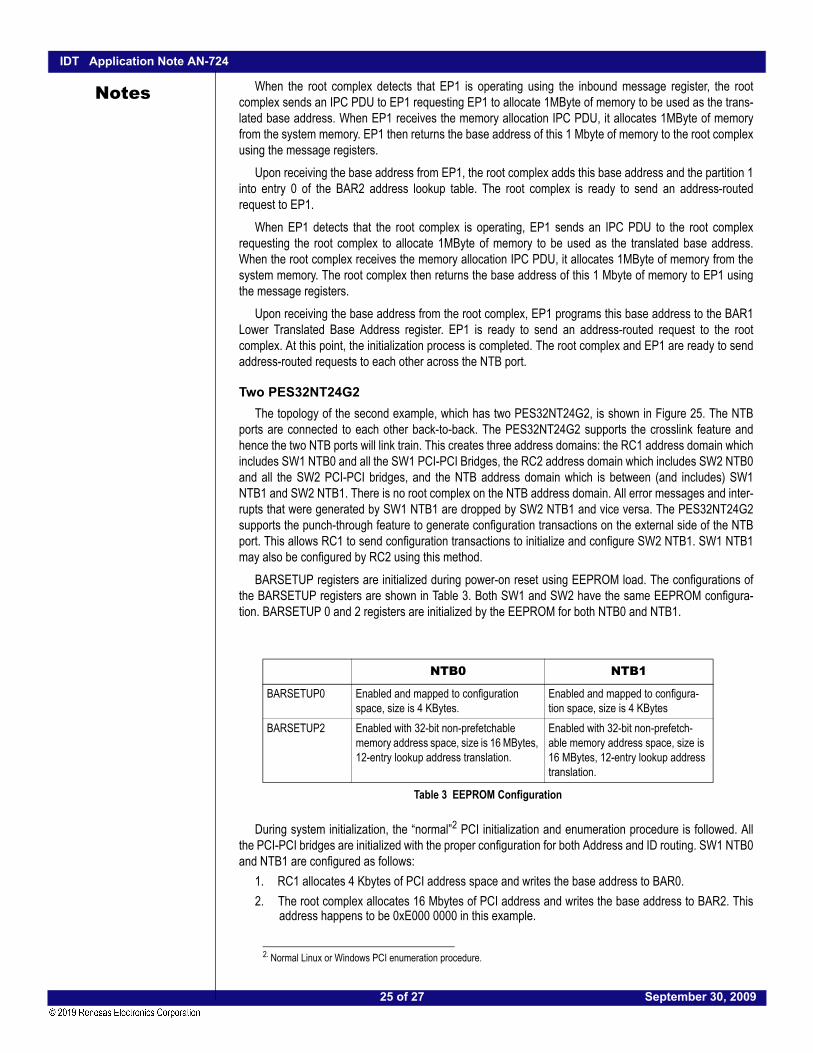
Two PES32NT24G2The topology of the second example, which has two PES32NT24G2, is shown in Figure 25. The NTB
ports are connected to each other back-to-back. The PES32NT24G2 supports the crosslink feature andhence the two NTB ports will link train. This creates three address domains: the RC1 address domain whichincludes SW1 NTB0 and all the SW1 PCI-PCI Bridges, the RC2 address domain which includes SW2 NTB0and all the SW2 PCI-PCI bridges, and the NTB address domain which is between (and includes) SW1NTB1 and SW2 NTB1. There is no root complex on the NTB address domain. All error messages and inter-rupts that were generated by SW1 NTB1 are dropped by SW2 NTB1 and vice versa. The PES32NT24G2supports the punch-through feature to generate configuration transactions on the external side of the NTBport. This allows RC1 to send configuration transactions to initialize and configure SW2 NTB1. SW1 NTB1may also be configured by RC2 using this method.
BARSETUP registers are initialized during power-on reset using EEPROM load. The configurations ofthe BARSETUP registers are shown in Table 3. Both SW1 and SW2 have the same EEPROM configura-tion. BARSETUP 0 and 2 registers are initialized by the EEPROM for both NTB0 and NTB1.
During system initialization, the “normal”2 PCI initialization and enumeration procedure is followed. Allthe PCI-PCI bridges are initialized with the proper configuration for both Address and ID routing. SW1 NTB0and NTB1 are configured as follows:
1. RC1 allocates 4 Kbytes of PCI address space and writes the base address to BAR0.2. The root complex allocates 16 Mbytes of PCI address and writes the base address to BAR2. This
address happens to be 0xE000 0000 in this example.
NTB0 NTB1
BARSETUP0 Enabled and mapped to configuration space, size is 4 KBytes.
Enabled and mapped to configura-tion space, size is 4 KBytes
BARSETUP2 Enabled with 32-bit non-prefetchable memory address space, size is 16 MBytes, 12-entry lookup address translation.
Enabled with 32-bit non-prefetch-able memory address space, size is 16 MBytes, 12-entry lookup address translation.
Table 3 EEPROM Configuration
2. Normal Linux or Windows PCI enumeration procedure.
25 of 27 September 30, 2009

IDT Application Note AN-724
Notes
3. Based on the vendor ID and device ID of the NT endpoint, RC1 loads and passes control to the NTBdevice driver.4. The NTB device driver sets the Memory Access Enable bit, Bus Master Enable bit, and the Comple-tion Enable bit on NTB0.
5. RC1 uses the punch-through feature on NTB1 to generate a configuration read request to get thevendor ID and device ID of the device that connects to NTB1. It discovers that it is connecting toanother NTB port. This is a back-to-back NTB connection.
6. The NTB device driver sets the Memory Access Enable bit, Bus Master Enable bit, and the Comple-tion Enable bit on NTB1.
7. The NTB device driver discovers the ID of RC1 to be 0.1.0 by reading the Requester ID Captureregister.
8. The NTB device driver discovers its port number by reading the PCIe Link Capabilities register. Theport number is used as an index to the Switch Port Control register to discover the partition number(0) of which this port is in.
9. The NTB device driver adds the partition number 0 and the ID 0.1.0 to entry 0 of the NT mappingtable.
10. The NTB device driver discovers the port number of NTB1 by reading the PCIe Link Capabilitiesregister. The port number is used as an index to the Switch Port Control register to discover the parti-tion number (1) of which NTB1 is in.
11. The NTB device driver adds the partition number 1 and the ID 0.16.0 to entry 1 of the NT mappingtable. NTB device driver always uses the ID 0.16.0 for back-to-back NTB connection. Any ID maybe chosen by the software designer.
12. The NTB device driver uses the punch-through feature to send a configuration read request to findout the BAR requirements for SW2 NTB1. SW2 BAR0 requires 4 KBytes of address space and SW2BAR1 requires 1 MByte of address space.
13. The NTB device driver sets SW2 NTB1 BAR0 to be 0x0000 0000 and SW2 NTB1 BAR2 to be 0x02000000. These values are chosen by the NTB device driver in this example and may contain anyvalues chosen by the system designer.
14. The NTB device driver adds partition 1 and the translated address 0x0000 0000 to entry 0 of theaddress lookup table for SW1 NTB0 BAR2. It also adds partition 1 and the translated address0x0200 0000 to entry 1 of the address lookup table for SW1 NTB0 BAR2. These translatedaddresses match the content of SW2 NTB1 BAR0 and BAR2. At this point, RC1 can access all theNTB registers of SW2 NTB1 by doing a memory read/write request to the address 0xE000 0000.
15. The NTB device driver writes a known pattern to the inbound message register of SW2 NTB0 usingthe SW2 NTB1 outbound message register. It then waits for RC2 to be ready by checking its inboundmessage register.
SW2 NTB0 and NTB1 are initialized in exactly the same way as SW1 NTB0 and NTB1.When RC1 detects that RC2 is operating using the SW1 NTB0 inbound message register, RC1 sends
an IPC PDU to RC2 requesting RC2 to allocate 1MByte of memory to be used as the translated baseaddress. When RC2 receives the memory allocation IPC PDU, it allocates 1MByte of memory from thesystem memory. RC2 then returns the base address of this 1 Mbyte of memory to RC1 using the SW1NTB1 message registers.
Upon receiving the base address from RC2, RC1 adds this base address and partition 0 to entry 0 of theSW2 NTB1 BAR2 address lookup table. RC1 is ready to send an address-routed request to RC2.
When RC2 detects that RC1 is operating using the SW2 NTB0 inbound message register, RC2 sendsan IPC PDU to RC1 requesting RC1 to allocate 1MByte of memory to be used as the translated baseaddress. When RC1 receives the memory allocation IPC PDU, it allocates 1MByte of memory from systemmemory. RC1 then returns the base address of this 1 Mbyte of memory to RC2 using the SW2 NTB1message registers.
26 of 27 September 30, 2009

IDT Application Note AN-724
Notes
Upon receiving the base address from RC1, RC2 adds this base address and partition 0 to entry 0 of theSW1 NTB1 BAR2 address lookup table. The RC2 is ready to send an address-routed request to RC1. Atthis point, the initialization process is completed. RC1 and RC2 are ready to send address-routed requeststo each other across the NTB port.SummaryNon-transparent bridging may be used to connect two or more root complexes in a PCIe system. This
allows multiple root complexes to exchange data with each other. Detailed procedures and a theory of oper-ation were given to show how a PES32NT24G2 forwards and translates PCIe transaction packets acrossan NTB port. As discussed above, the PES32NT24G2 provides all the features — such as address transla-tion, ID translation, interprocessor communication features, and error checking and handling — to efficientlysupport a multiple root complex system.
ReferencesPCI Express Base Specification Revision 1.1PCI Express Base Specification Revision 2.0IDT 89HPES32NT24G2 PCI Express® Switch User ManualApplication Note AN-713, Introduction to the PES32NT24G2 PCI Express® Switch Features, August,
2009.
Application Note AN-722, Inter-Domain Communication in the PES32NT24G2 PCI Express® Switch
27 of 27 September 30, 2009

Corporate HeadquartersTOYOSU FORESIA, 3-2-24 Toyosu,Koto-ku, Tokyo 135-0061, Japanwww.renesas.com
Contact InformationFor further information on a product, technology, the most up-to-date version of a document, or your nearest sales office, please visit:www.renesas.com/contact/
TrademarksRenesas and the Renesas logo are trademarks of Renesas Electronics Corporation. All trademarks and registered trademarks are the property of their respective owners.
IMPORTANT NOTICE AND DISCLAIMER
RENESAS ELECTRONICS CORPORATION AND ITS SUBSIDIARIES (“RENESAS”) PROVIDES TECHNICAL SPECIFICATIONS AND RELIABILITY DATA (INCLUDING DATASHEETS), DESIGN RESOURCES (INCLUDING REFERENCE DESIGNS), APPLICATION OR OTHER DESIGN ADVICE, WEB TOOLS, SAFETY INFORMATION, AND OTHER RESOURCES “AS IS” AND WITH ALL FAULTS, AND DISCLAIMS ALL WARRANTIES, EXPRESS OR IMPLIED, INCLUDING, WITHOUT LIMITATION, ANY IMPLIED WARRANTIES OF MERCHANTABILITY, FITNESS FOR A PARTICULAR PURPOSE, OR NON-INFRINGEMENT OF THIRD PARTY INTELLECTUAL PROPERTY RIGHTS.
These resources are intended for developers skilled in the art designing with Renesas products. You are solely responsible for (1) selecting the appropriate products for your application, (2) designing, validating, and testing your application, and (3) ensuring your application meets applicable standards, and any other safety, security, or other requirements. These resources are subject to change without notice. Renesas grants you permission to use these resources only for development of an application that uses Renesas products. Other reproduction or use of these resources is strictly prohibited. No license is granted to any other Renesas intellectual property or to any third party intellectual property. Renesas disclaims responsibility for, and you will fully indemnify Renesas and its representatives against, any claims, damages, costs, losses, or liabilities arising out of your use of these resources. Renesas' products are provided only subject to Renesas' Terms and Conditions of Sale or other applicable terms agreed to in writing. No use of any Renesas resources expands or otherwise alters any applicable warranties or warranty disclaimers for these products.
(Rev.1.0 Mar 2020)
© 2020 Renesas Electronics Corporation. All rights reserved.