an active roll reduction system using free flooding …€¦ · an active roll reduction system...
TRANSCRIPT
World Maritime Technology Conference 29 May – 1 June 2012, Saint-Petersburg, Russia
1
AN ACTIVE ROLL REDUCTION SYSTEM USING FREE FLOODING TANKS CONTROLLED BY VACUUM PUMPS
Karl H. Halse, Vilmar Æsøy and Ove Sporsheim1)
Aalesund University College Larsgårdsv. 2, 6025 Ålesund, Norway
1) Marine Roll and Pitch Control AS Britvegen 4, 6410 Molde, Norway
ABSTRACT Severe ship motion is often the limiting factor for performing offshore marine operations from a ship-shaped single hull vessel. Excessive motions may complicate the operations and may cause damage to the ship hull structure, the ship machinery and/or the ship equipment. Both human factors as acceleration induced human fatigue, and technical factors as structural failure due to e.g. slamming loads, propeller ventilation or inertia forces due to high accelerations, can be the reason to abort a marine operation. The roll motion is particularly important, as it has very low damping and may also lead to capsizing. Roll reduction systems are often classified into passive and active systems. An example of a passive system is the free surface tank, where water (or some other fluid) is allowed to flow freely inside the tank, and the effect of the internal flow is to counteract the motion of the vessel. The idea behind the active systems is that the counteracting moment is controlled in some way or another. Over the years, several various systems have been proposed to actively reduce the roll motion. This paper presents a system using ballast water tanks which are open to the sea and where the amount of water in the tanks is controlled by vacuum pumps pressing water into and out of the tanks. The control algorithm used to control the necessary flow of water in and out of the tanks is a simple PID algorithm. The method is modeled as a single-degree-of-freedom system excited by a harmonic wave force. Analyses are performed to evaluate the necessary available tank volume and/or the necessary pump capacity to reduce the roll motion sufficiently. The system is also tested in a model test, and results from the analyses are compared with the model test results.
INTRODUCTION
For ocean-going vessels, excessive motions may complicate the operations on-board and may cause damage to the ship machinery and ship equipment. Over the years various methods have appeared to minimize the motions, thereby to improve the operability of the vessel.
• Heave motion; concept of minimizing the heave motion has lead to the invention of semi-submersible platforms as well as the SWATH (Small Waterplane Area Twin Hull) concept.
• Roll motion; various methods exists, passive methods utilizing the effect of the free surface and various versions of active methods where water has been pumped from one tank to another, but also from one tank and directly to the sea.
• Pitch motion; various methods have been proposed, but none have been put into practical use.
A novel patented concept has been proposed by the small company Marine Roll and Pitch Control (MRPC) (www.mrpc.no). This concept builds on the idea of free-flooding tanks or n-tanks, tanks which are open to the sea at the bottom. The MRPC system makes use of high volume air compressors working with low pressure and vacuum to control the amount of air (and thus water) in the tanks. In this way a counter moment which seeks to balance the exciting moment from the waves can be established. The present report evaluates the effect of this concept to the roll motion of a seismic vessel in beam seas. The approach followed in this work is to simplify the roll motion of the vessel as a single-degree-of-freedom (SDOF) system. A mathematical model of

2
the SDOF system with corresponding control system is established. The effect of the actively controlled roll reduction system has been tested for a range of control parameters, to tune the system to provide an optimal roll reduction. The system has been tested with a range of available tank volumes to find the amount of water necessary to dampen the roll motion. Furthermore, the system has been tested with varying pump capacities to study how much water the pumps must be able to transfer in order to transport the necessary amount of water in and out of the tanks. The sensitivity of the system to varying wave amplitudes has also been studied.
1. SYSTEM DESCRIPTION
1.1. Overview of systems for roll reduction For ocean-going vessels, excessive motions may complicate the operations on-board and may cause damage to the ship machinery and ship equipment. The roll motion is particularly important, as it has very low damping and may also lead to capsizing if the roll motion gets severe. Over the years several means have been suggested to introduce damping to the roll motion of ships. Roll-damping devices which have been introduced to reduce the roll motion of ships include gyrosopic stabilizers, active rudder control, fin stabilizers and anti-roll tanks. An overview of various roll-damping devices may be found in student theses as the one by Treakle (1998), or in general text books about naval architecture as e.g. Lloyd (1989). A more recent review paper on anti-roll tanks is presented by Moaleji and Greig (2007). The roll-damping devices may be classified into two different types of system.
1. systems which seek to move the centre of gravity of the vessel transversely to provide the restoring moment
2. systems which provides the restoring force directly in some way or another
1.2. Systems which seek to move the centre of gravity
Several systems to move the centre of gravity transversely have been proposed. In the beginning of the previous century it was proposed to use a gyroscopic stabilizer, an idea which was adopted on a German torpedo boat in 1906. The concept had severe limitations. Firstly, high concentrated loads caused large torsion moments in the hull during roll and pitch, and have unfavorable consequences on the ship stability. Secondly, this kind of system requires a considerable amount of power and has a slow response time. The concept has not won much attention. As early as in 1861, Froude studied the effect of a simple partially filled rectangular tank, a “free-surface tank”, on the roll motion of a ship. Some twenty years later (in 1883) this idea was applied by Watts who proposed to use a large, uniform cross-section tank partly filled with water, extending from ship side to ship side and place it well above the centre of gravity of the vessel. The purpose of the tanks was to reduce the roll motion of the vessel. The roll motion of the ship caused the water to move from side to side in the tank, see Fig. 1, and the amount of water provided a counter moment which attempted to balance the wave excitation moment. The mechanisms of the internal wave action inside the rectangular tank on a moving vessel, and the resulting roll damping moment was explained in detail by Watts in a series of papers published at the Royal Institution of Naval Architects (RINA) in 1883 and 1885. Froude contributed also in this discussion. Although the tank acted satisfactorily, and the mechanisms were clearly understood, the idea lost its interest in the years that followed, and was long forgotten. In 1966, Bosch and Vugts (1966) again found interest in this simple idea, and investigated the concept of using rectangular tanks for roll reduction of ships. They experienced that a roll reduction of up to 80 % was achievable in harmonic waves, and up to 50 % in irregular waves. They also found that by adjusting the filling level of the tank, the roll damping could be adjusted to different wave periods. The roll damping
Fig.1: The principle of the rectangular free surface tank proposed by Watts in 1883 is shown. a) maximum roll rate to starboard; maximum stabilizing moment to port, b) maximum roll to starboard; zero stabilizing moment, c) maximum roll rate to port; maximum stabilizing moment to starboard, d) maximum roll to port; zero stabilizing moment (from Moaleji and Greig, 2007).
3
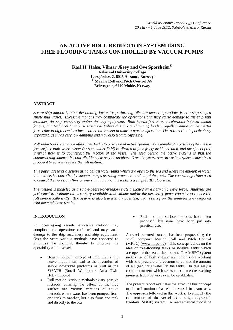
Fig. 2: The principle of the U-tube tank suggested by Frahm in 1911 (Moaleji and Greig, 2006b). is at its maximum when the natural period of the tank is tuned to the roll period of the ship. An important disadvantage of such tanks is that it is difficult to control the water as it flows to one side of the ship. Hence, the stability of the vessel is reduced and the safety may be threatened. Furthermore, optimal use of a free-flooding tank requires the tanks to be located above the centre of gravity. Consequently, the tanks are found in one of the most usable spaces onboard the vessel. For many types of vessels this makes it impossible to use this kind of anti-roll tanks. In 1911 an improved solution to the inherent problems of a rectangular tank was suggested by Frahm in terms of a U-shaped tank, see Fig. 2. Two reservoirs were connected by a water duct, and at the top by an air duct. This idea removed the most obvious disadvantages of the rectangular free surface tanks. It was easier to control the flow of water (through a confined duct connecting the two reservoirs) and the U-tube tank did not occupy the most usable space in the ship. The ducts can be controlled by valves and pumps, and several authors have adopted and improved this idea since then, e.g. Phairoh and Huang (2005). In recent years the German company Intering, now owned by Rolls-Royce, is among the companies offering a system based on Frahm's original idea. Some have suggested modification to Frahm’s original idea by opening the tanks to the sea. This concept has been called “free-flooding” tanks or “external” tanks. However, the tanks are not necessarily external (in the meaning “on the outside of the hull”), and the flow in and out of the tanks may be controlled (not “free-flooding”), hence the name “n-tanks” as suggested by Moaleji and Greig (2006b) appears to be a better word for this concept. To our knowledge, the first attempt of using n-tanks to
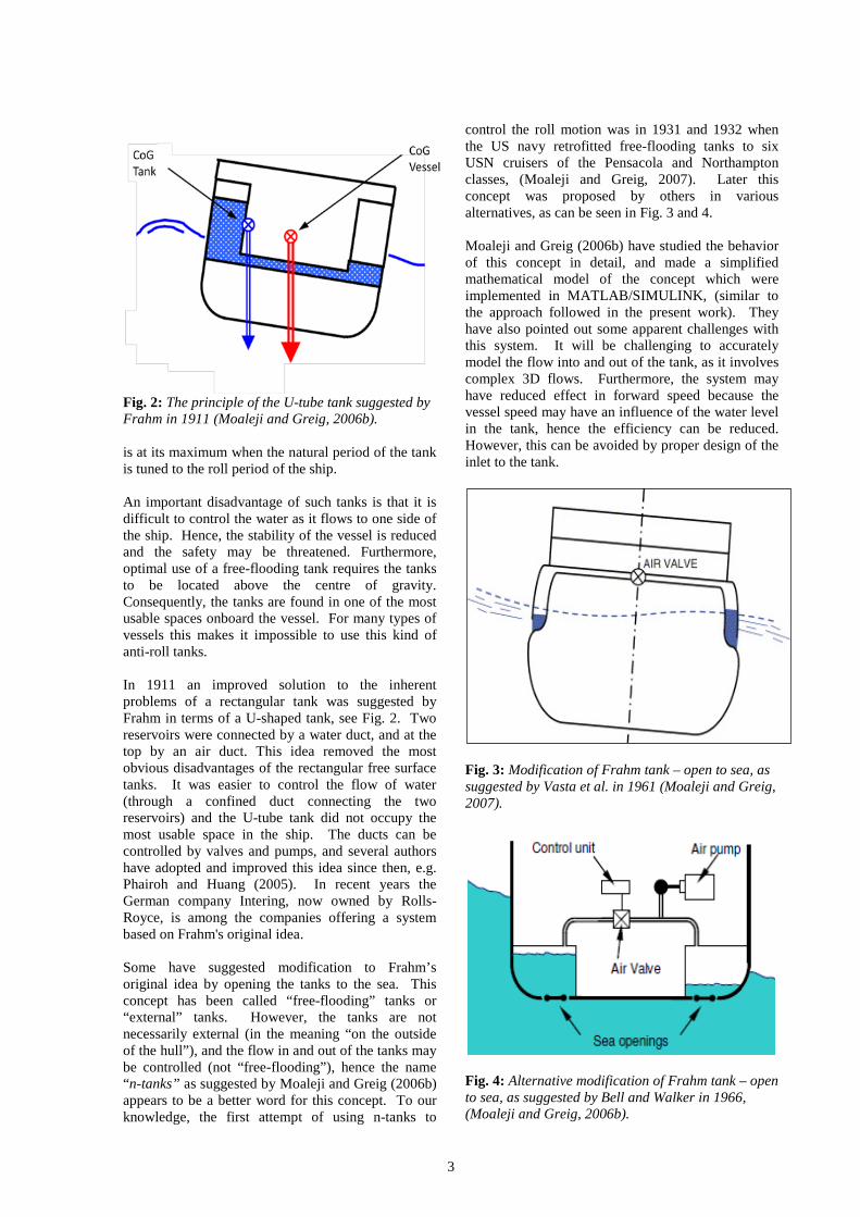
control the roll motion was in 1931 and 1932 when the US navy retrofitted free-flooding tanks to six USN cruisers of the Pensacola and Northampton classes, (Moaleji and Greig, 2007). Later this concept was proposed by others in various alternatives, as can be seen in Fig. 3 and 4. Moaleji and Greig (2006b) have studied the behavior of this concept in detail, and made a simplified mathematical model of the concept which were implemented in MATLAB/SIMULINK, (similar to the approach followed in the present work). They have also pointed out some apparent challenges with this system. It will be challenging to accurately model the flow into and out of the tank, as it involves complex 3D flows. Furthermore, the system may have reduced effect in forward speed because the vessel speed may have an influence of the water level in the tank, hence the efficiency can be reduced. However, this can be avoided by proper design of the inlet to the tank.
Fig. 3: Modification of Frahm tank – open to sea, as suggested by Vasta et al. in 1961 (Moaleji and Greig, 2007).
Fig. 4: Alternative modification of Frahm tank – open to sea, as suggested by Bell and Walker in 1966, (Moaleji and Greig, 2006b).

4
Abdel Gawad et al. (2001) have modeled the roll motion of a vessel as a simple SDOF system and combined it with one-dimensional Euler equation to model the fluid flow in the U-tube. In this way, it was possible to tune the tank dimensions to most effectively dampen the vessel motions. Building on this work, Youssef et al. (2002) modeled the vessel motion as a 6DOF model and included the one-dimensional Euler equation for the fluid flow. In this way, the authors could study e.g. the effect of varying wave heading. Later Marzouk and Nayfeh (2009) have developed the model further and used it to study the roll reduction effect of both passive and active U-tube tanks. Not surprisingly, they found that the active anti-roll tanks were more effective in reducing the roll motion of a cargo ship in rough conditions for a variety of wave headings. The roll amplitude was reduced with as much as 98% is some cases. 1.2. Systems which seek to provide the restoring
force Systems which seek to reduce the roll response by providing a restoring force include passive systems like bilge keels or fins protruding from the hull of the ship and active systems where the fins are controlled by some kind of feed-back control loop. Bilge keels are used very often, as they are easy to install and have no significant cost impact. However, for the bilge keels to offer significant roll reduction, they must be rather large. When the bilge keels get too large they are impractical and may cause operational challenges. Consequently, most bilge keels are relatively small (approximately 30-40 cm), and the roll reduction caused by the bilge keels is limited. Active fin roll reduction systems consist of airfoil-shaped, wing-like projections. The fins develop a hydrodynamic lift as the ship is moving through the water. The generated lift force is proportional to the square of the ship speed, to the angle of attack and the lift coefficient of the foil profile. Over the recent years, several authors have also proposed to use the rudders active in order to reduce the damping, (see e.g. the overview given by Marzouk and Nayfeh, 2009). However, the size of passive fins must be extremely large in order to produce any significant effect, and so their use is limited. Active fin systems have been utilized since the earliest attempts by the English developer Wilson in 1890 and Motora in Japan in the early 1900's. The most significant advances came between World War I and World War II when Denny, Brown Brothers, and the Admiralty Research Lab in the UK began a joint effort to develop an active fin system. Their scheme used wing like appendages controlled by gyroscopes that measured roll position and roll rate. Active fin systems have a major drawback, however: the effect of the fins is negligible at slow forward speed. In
1910, Cremieu originally tested moving weight systems. He used a 10-ton mass mounted on a curved track that was immersed in a solution of glycerin and water. The mass was free to move in the solution that helped dissipate the kinetic energy of the system. Unfortunately, the system was not tuned properly and the mass impacted the stops at either end of the tracks and created large shocks. Norden was granted a US patent for a similar scheme in 1929. The use of moving masses has not been fully explored until recent years due to the size of the mass necessary to obtain a significant reduction in rolling motion. In 1989 Baitis and Schmidt presented the use of rudder roll stabilization employed by the U.S. Navy on a DD-963 (Spruance) class destroyer. The rudder roll stabilizer utilized the roll moment generated by the large rudders on the ship to dampen the roll motion without drastically altering the ship's course. The installed systems produced reductions in roll motion of approximately 40%. The advantage of such a system is that no large additional systems need to be installed on the ship. The rudder roll stabilization system is still one of the primary roll control devices in use on U.S. Navy ships, yet it loses effectiveness at reduced speeds. Recently, the advance of electronic control theory and applications has made it possible to control the roll motion by using the azimuthing propellers via a proportional-integral-derivative (PID) feedback. McTaggart (2008) showed that the roll motion of a 900 tons naval vessel could be reduced by about 50% in rough beam seas by using the side force from the azimuthing propellers. The roll reduction drops rapidly as the heading angle is changed away from the beam sea case. The Voith-Schneider propellers have proven to be particularly effective to provide side thrust to reduce the roll motion. In Jürgens and Palm (2009) a 44m yacht was tested in bow quartering seas, and the Voith-Schneider propellers managed to reduce the roll response by approximately 65%. 1.3. The proposed method The system studied in this work is an active system with free-flooding tanks or n-tanks. In a traditional active roll reduction system, some kind of pumping devices (either by pumping air or by pumping water) will be used to transfer water from one tank in the ship and to another tank at another location. Van Daalen et al.(2000) have modeled the water flow in the tanks by using a Volume of Fluid (VoF) based Navier-Stokes solver. This is necessary if the intention is to study accurately how the fluid flows in the ducts and through the openings in the hull. However, in this work we have used a much simpler approach for the flow of water, as our focus has been to study the vessel dynamics.

5
The proposed MRPC system uses ballast water tanks which are open to the sea. The necessary counter moment to balance the exciting moment from the waves is obtained by filling/emptying the open tanks directly to/from the sea. The system relies on the application of high volume air compressors working at low pressure to transfer air out of the tanks. The water will then flow freely into the available space in the tanks. In this way the power demand is significantly reduced, compared to the case where water is transferred from one side of the vessel to the other. Furthermore, in some ship designs it will be difficult to transfer water from one side to the other (e.g. in a catamaran). The following parameters will influence the effect of the proposed system
• Available tank volume (size and number of tanks)
• Pump characteristics or restrictions to the pump capacity
• Size and shape of the openings to the sea • The chosen control algorithm (P-control,
PD-control or PID-control and the value of the associated control parameters)
• Available control signal (angle, angular velocity, or acceleration)
All of these parameters have been considered in this work. Parameters variations of some of them are presented in this paper. 2. THE MATHEMATICAL MODEL 2.1. Simplified vessel motions – roll The vessel motions can be simplified with a single degree of freedom (SDOF) model. An SDOF model for the roll motion can be written as
𝐽���̈� + 𝐵���̇� + 𝐶��𝜙 = 𝜏��� (1)
where 𝐽��,𝐵�� and 𝐶�� are the inertia, damping and stiffness coefficients, respectively. 𝜙 is the roll angle, and 𝜏��� is the total external excitation.
The stiffness coefficient in roll is given as 𝐶�� =𝑀 𝑔 𝐺𝑀� and the damping coefficient 𝐵�� is defined to reflect a typical hydrodynamic roll damping of 10%.
The total inertia of the system is given as
𝐽�� = 𝑀𝑟�� + 𝐴�� (2)
where M is the mass displacement of the vessel, 𝑟�� is the radius of gyration in roll and 𝐴�� is the frequency dependent hydrodynamic added mass. In this simplified vessel model we have assumed a constant
added mass contribution. In addition, the varying water level in the tanks will contribute to the overall inertia. However, as the water level is the parameter we want to use to control the roll response, this is considered as a part of the external excitation (or external disturbance).
The total external excitation contains contribution both from the waves and the varying water level of the roll reduction tanks.
𝜏��� = 𝜏���� + 𝜏�� = 𝜏���� + 𝑚��𝑅�� (3) where 𝑚 is the mass of the water in the tank, and 𝑅�� is the arm from the point around which the vessel rotates to the centre of the tank.
In reality, the tank disturbance has two contributions, one from added water on one side of the vessel and another from removed water from the other side of the vessel. In this work we have assumed that the two tanks in question are identical and that the two processes (emptying and filling) act at the same speed thus we have chosen to model them as one single process. Hence, filling our single tank will lead to a positive roll moment (e.g. towards starboard), whereas emptying the tank leads to a negative roll moment (i.e. towards port). 2.2. External disturbance – Wave excitation model The wave excitation is modeled as simple as possible, the main emphasis of this study is to see how the active control algorithm can handle a regular wave excitation. In reality, the added mass coefficients, the hydrodynamic damping coefficient, and the wave excitation will all be frequency dependent, whereas in this work we have used fixed coefficients and a simplified hydrodynamic forcing function.
An alternative used by several authors is given as (Taylan, 2000)
𝜏��� = 𝜔��𝛼�𝐽�� cos𝜔�𝑡 (4)
where, 𝜔� is the frequency of encounter, 𝛼� is the maximum wave slope and 𝐽�� is the moment of inertia in roll. The amplitude of the forcing function is frequency dependent and wave amplitude dependent (since 𝛼� = 𝑘𝜁�, where k is the wave number and 𝜁� is the wave amplitude).
2.3. Modeling the restoring moment The restoring moment or the roll damping moment is provided by the varying water level in the tanks. As previously mentioned, we have assumed that the two tanks are identical, located at the same distance from the centre line and that filling of SB tank and
6
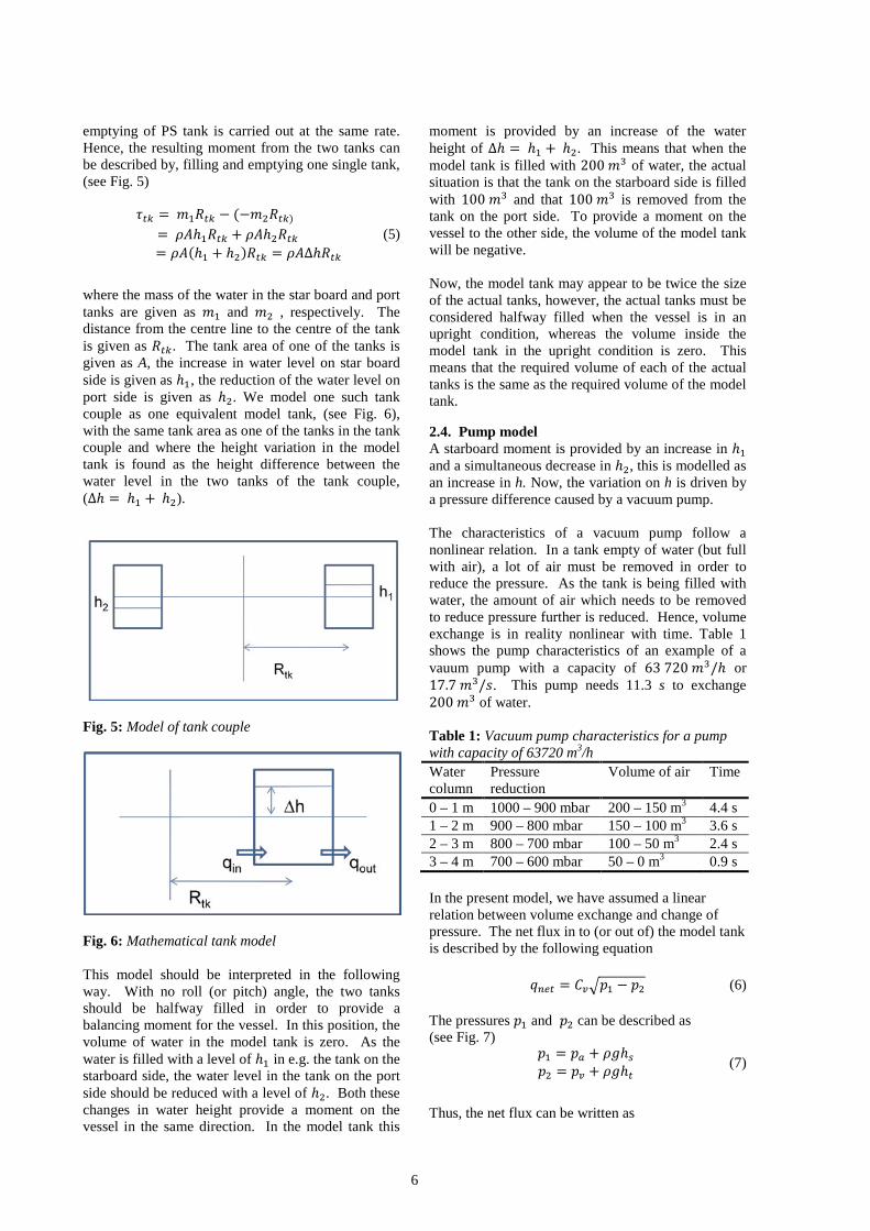
emptying of PS tank is carried out at the same rate. Hence, the resulting moment from the two tanks can be described by, filling and emptying one single tank, (see Fig. 5)
𝜏�� = 𝑚�𝑅�� − (−𝑚�𝑅��) = 𝜌𝐴ℎ�𝑅�� + 𝜌𝐴ℎ�𝑅�� = 𝜌𝐴(ℎ� + ℎ�)𝑅�� = 𝜌𝐴∆ℎ𝑅��
(5)
where the mass of the water in the star board and port tanks are given as 𝑚� and 𝑚� , respectively. The distance from the centre line to the centre of the tank is given as 𝑅��. The tank area of one of the tanks is given as A, the increase in water level on star board side is given as ℎ�, the reduction of the water level on port side is given as ℎ�. We model one such tank couple as one equivalent model tank, (see Fig. 6), with the same tank area as one of the tanks in the tank couple and where the height variation in the model tank is found as the height difference between the water level in the two tanks of the tank couple, (∆ℎ = ℎ� + ℎ�).
Fig. 5: Model of tank couple
Fig. 6: Mathematical tank model This model should be interpreted in the following way. With no roll (or pitch) angle, the two tanks should be halfway filled in order to provide a balancing moment for the vessel. In this position, the volume of water in the model tank is zero. As the water is filled with a level of ℎ� in e.g. the tank on the starboard side, the water level in the tank on the port side should be reduced with a level of ℎ�. Both these changes in water height provide a moment on the vessel in the same direction. In the model tank this
moment is provided by an increase of the water height of ∆ℎ = ℎ� + ℎ�. This means that when the model tank is filled with 200 𝑚� of water, the actual situation is that the tank on the starboard side is filled with 100 𝑚� and that 100 𝑚� is removed from the tank on the port side. To provide a moment on the vessel to the other side, the volume of the model tank will be negative. Now, the model tank may appear to be twice the size of the actual tanks, however, the actual tanks must be considered halfway filled when the vessel is in an upright condition, whereas the volume inside the model tank in the upright condition is zero. This means that the required volume of each of the actual tanks is the same as the required volume of the model tank. 2.4. Pump model A starboard moment is provided by an increase in ℎ� and a simultaneous decrease in ℎ�, this is modelled as an increase in h. Now, the variation on h is driven by a pressure difference caused by a vacuum pump. The characteristics of a vacuum pump follow a nonlinear relation. In a tank empty of water (but full with air), a lot of air must be removed in order to reduce the pressure. As the tank is being filled with water, the amount of air which needs to be removed to reduce pressure further is reduced. Hence, volume exchange is in reality nonlinear with time. Table 1 shows the pump characteristics of an example of a vauum pump with a capacity of 63 720 𝑚�/ℎ or 17.7 𝑚�/𝑠. This pump needs 11.3 s to exchange 200 𝑚� of water. Table 1: Vacuum pump characteristics for a pump with capacity of 63720 m3/h Water column
Pressure reduction
Volume of air Time
0 – 1 m 1000 – 900 mbar 200 – 150 m3 4.4 s 1 – 2 m 900 – 800 mbar 150 – 100 m3 3.6 s 2 – 3 m 800 – 700 mbar 100 – 50 m3 2.4 s 3 – 4 m 700 – 600 mbar 50 – 0 m3 0.9 s In the present model, we have assumed a linear relation between volume exchange and change of pressure. The net flux in to (or out of) the model tank is described by the following equation
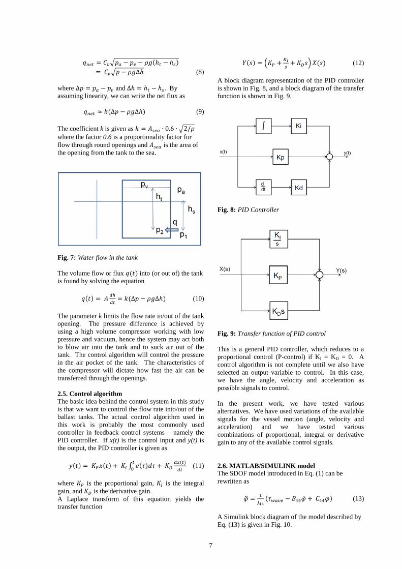
𝑞��� = 𝐶��𝑝� − 𝑝� (6) The pressures 𝑝� and 𝑝� can be described as (see Fig. 7)
𝑝� = 𝑝� + 𝜌𝑔ℎ�𝑝� = 𝑝� + 𝜌𝑔ℎ�
(7)
Thus, the net flux can be written as
7
𝑞��� = 𝐶��𝑝� − 𝑝� − 𝜌𝑔(ℎ� − ℎ�) = 𝐶��𝑝 − 𝜌𝑔∆ℎ (8)
where ∆𝑝 = 𝑝� − 𝑝� and ∆ℎ = ℎ� − ℎ�. By assuming linearity, we can write the net flux as
𝑞��� ≈ 𝑘(∆𝑝 − 𝜌𝑔∆ℎ) (9) The coefficient k is given as 𝑘 = 𝐴��� ∙ 0.6 ∙ �2/𝜌 where the factor 0.6 is a proportionality factor for flow through round openings and 𝐴��� is the area of the opening from the tank to the sea.
Fig. 7: Water flow in the tank The volume flow or flux 𝑞(𝑡) into (or out of) the tank is found by solving the equation
𝑞(𝑡) = 𝐴 ����
= 𝑘(∆𝑝 − 𝜌𝑔∆ℎ) (10) The parameter k limits the flow rate in/out of the tank opening. The pressure difference is achieved by using a high volume compressor working with low pressure and vacuum, hence the system may act both to blow air into the tank and to suck air out of the tank. The control algorithm will control the pressure in the air pocket of the tank. The characteristics of the compressor will dictate how fast the air can be transferred through the openings. 2.5. Control algorithm The basic idea behind the control system in this study is that we want to control the flow rate into/out of the ballast tanks. The actual control algorithm used in this work is probably the most commonly used controller in feedback control systems – namely the PID controller. If x(t) is the control input and y(t) is the output, the PID controller is given as
𝑦(𝑡) = 𝐾�𝑥(𝑡) + 𝐾� ∫ 𝑒(𝜏)𝑑𝜏�� + 𝐾�
��(�)��
(11) where 𝐾� is the proportional gain, 𝐾� is the integral gain, and 𝐾� is the derivative gain. A Laplace transform of this equation yields the transfer function
𝑌(𝑠) = �𝐾� + ���
+ 𝐾�𝑠�𝑋(𝑠) (12) A block diagram representation of the PID controller is shown in Fig. 8, and a block diagram of the transfer function is shown in Fig. 9.
Fig. 8: PID Controller
Fig. 9: Transfer function of PID control This is a general PID controller, which reduces to a proportional control (P-control) if KI = KD = 0. A control algorithm is not complete until we also have selected an output variable to control. In this case, we have the angle, velocity and acceleration as possible signals to control. In the present work, we have tested various alternatives. We have used variations of the available signals for the vessel motion (angle, velocity and acceleration) and we have tested various combinations of proportional, integral or derivative gain to any of the available control signals. 2.6. MATLAB/SIMULINK model The SDOF model introduced in Eq. (1) can be rewritten as
�̈� = ����
(𝜏���� − 𝐵���̇� + 𝐶��𝜑) (13) A Simulink block diagram of the model described by Eq. (13) is given in Fig. 10.
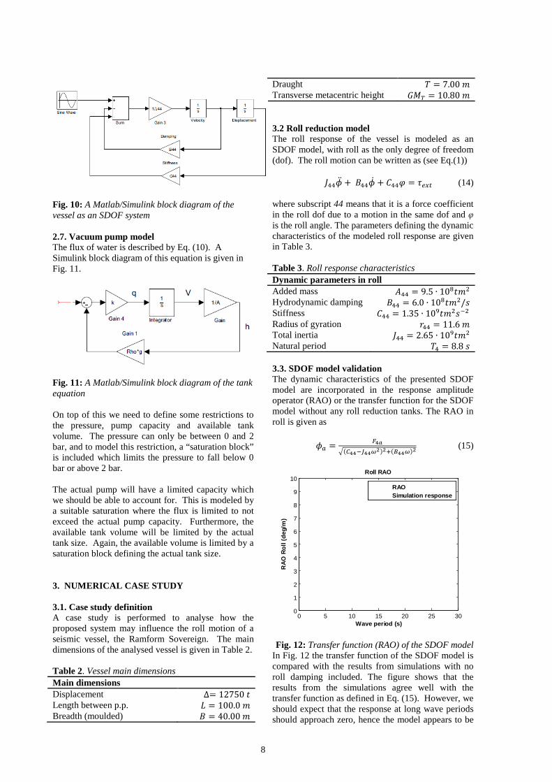
8
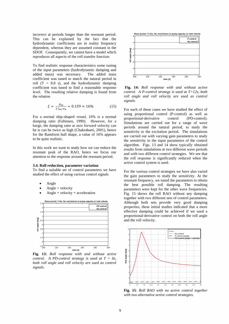
Fig. 10: A Matlab/Simulink block diagram of the vessel as an SDOF system 2.7. Vacuum pump model The flux of water is described by Eq. (10). A Simulink block diagram of this equation is given in Fig. 11.
Fig. 11: A Matlab/Simulink block diagram of the tank equation On top of this we need to define some restrictions to the pressure, pump capacity and available tank volume. The pressure can only be between 0 and 2 bar, and to model this restriction, a “saturation block” is included which limits the pressure to fall below 0 bar or above 2 bar. The actual pump will have a limited capacity which we should be able to account for. This is modeled by a suitable saturation where the flux is limited to not exceed the actual pump capacity. Furthermore, the available tank volume will be limited by the actual tank size. Again, the available volume is limited by a saturation block defining the actual tank size.
3. NUMERICAL CASE STUDY 3.1. Case study definition A case study is performed to analyse how the proposed system may influence the roll motion of a seismic vessel, the Ramform Sovereign. The main dimensions of the analysed vessel is given in Table 2. Table 2. Vessel main dimensions Main dimensions Displacement ∆= 12750 𝑡 Length between p.p. 𝐿 = 100.0 𝑚 Breadth (moulded) 𝐵 = 40.00 𝑚
Draught 𝑇 = 7.00 𝑚 Transverse metacentric height 𝐺𝑀� = 10.80 𝑚 3.2 Roll reduction model The roll response of the vessel is modeled as an SDOF model, with roll as the only degree of freedom (dof). The roll motion can be written as (see Eq.(1))
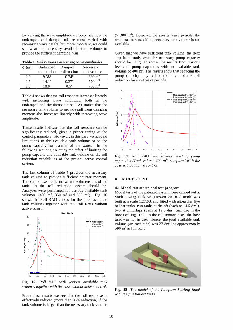
𝐽���̈� + 𝐵���̇� + 𝐶��𝜑 = 𝜏��� (14) where subscript 44 means that it is a force coefficient in the roll dof due to a motion in the same dof and φ is the roll angle. The parameters defining the dynamic characteristics of the modeled roll response are given in Table 3. Table 3. Roll response characteristics Dynamic parameters in roll Added mass 𝐴�� = 9.5 ∙ 10�𝑡𝑚� Hydrodynamic damping 𝐵�� = 6.0 ∙ 10�𝑡𝑚�/𝑠 Stiffness 𝐶�� = 1.35 ∙ 10�𝑡𝑚�𝑠�� Radius of gyration 𝑟�� = 11.6 𝑚 Total inertia 𝐽�� = 2.65 ∙ 10�𝑡𝑚� Natural period 𝑇� = 8.8 𝑠 3.3. SDOF model validation The dynamic characteristics of the presented SDOF model are incorporated in the response amplitude operator (RAO) or the transfer function for the SDOF model without any roll reduction tanks. The RAO in roll is given as
𝜙� = ����(���������)��(����)�
(15)
Fig. 12: Transfer function (RAO) of the SDOF model
In Fig. 12 the transfer function of the SDOF model is compared with the results from simulations with no roll damping included. The figure shows that the results from the simulations agree well with the transfer function as defined in Eq. (15). However, we should expect that the response at long wave periods should approach zero, hence the model appears to be
0 5 10 15 20 25 300
1
2
3
4
5
6
7
8
9
10
Wave period (s)
RAO
Rol
l (de
g/m
)
Roll RAO
RAOSimulation response
9
incorrect at periods longer than the resonant period. This can be explained by the fact that the hydrodynamic coefficients are in reality frequency dependent, whereas they are assumed constant in the SDOF. Consequently, we cannot have a model which reproduces all aspects of the roll transfer function.
To find realistic response characteristics some tuning of the input parameters (hydrodynamic damping and added mass) was necessary. The added mass coefficient was tuned to match the natural period in roll (T = 8.8 s), and the hydrodynamic damping coefficient was tuned to find a reasonable response level. The resulting relative damping is found from the relation
𝜉 = ����∙���∙��
= 0.159 ≈ 16% (15) For a normal ship-shaped vessel, 10% is a normal damping ratio (Faltinsen, 1990). However, for a barge, the damping ratio at zero forward velocity can be is can be twice as high (Chakrabarti, 2001), hence for the Ramform hull shape, a value of 16% appears to be quite realistic.
In this work we want to study how we can reduce the resonant peak of the RAO, hence we focus our attention to the response around the resonant period. 3.4. Roll reduction, parameter variation To find a suitable set of control parameters we have studied the effect of using various control signals
• Angle • Angle + velocity • Angle + velocity + acceleration
Fig. 13: Roll response with and without active control. A PD-control strategy is used at T = 6s, both roll angle and roll velocity are used as control signals.
Fig. 14: Roll response with and without active control. A P-control strategy is used at T=12s, both roll angle and roll velocity are used as control signals. For each of these cases we have studied the effect of using proportional control (P-control) as well as proportional-derivative control (PD-control). Simulations are carried out for a range of wave periods around the natural period, to study the sensitivity to the excitation period. The simulations are carried out with varying gain parameters to study the sensitivity to the input parameters of the control algorithm. Figs. 13 and 14 show typically obtained results from simulations at two different wave periods and with two different control strategies. We see that the roll response is significantly reduced when the active control system is used. For the various control strategies we have also varied the gain parameters to study the sensitivity. At the resonant frequency, we tuned the parameters to obtain the best possible roll damping. The resulting parameters were kept for the other wave frequencies. Fig. 15 shows the roll RAO without any damping together with two different sets of control parameters. Although both sets provide very good damping properties, these initial studies indicated that a more effective damping could be achieved if we used a proportional-derivative control on both the roll angle and the roll velocity.
Fig. 15: Roll RAO with no active control together with two alternative active control strategies.
200 210 220 230 240 250-2.5
-2
-1.5
-1
-0.5
0
0.5
1
1.5
2
2.5Wave period, T=6s, No restrictions to pump capacity or tank volume
time [s]
roll
angl
e [d
eg]
PD controlNo control
200 210 220 230 240 250-6
-4
-2
0
2
4
6Wave period, T=12s, No restrictions to pump capacity or tank volume
time [s]
roll
angl
e [d
eg]
P controlNo control
Ramform.xlsx1Wave period (s)
Rol
l ang
le (d
eg)
5 7.5 10 12.5 15 17.5 20 22.5 25 27.5 300
1
2
3
4
5
6
7
8
9
10
No controlP-control (angle)PD-control (angle + velocity)
10
By varying the wave amplitude we could see how the undamped and damped roll response varied with increasing wave height, but more important, we could see what the necessary available tank volume to provide the sufficient damping, was. Table 4. Roll response at varying wave amplitudes 𝜁�(m) Undamped
roll motion Damped roll motion
Necessary tank volume
1.0 9.38° 0.24° 380 m3 1.5 14.1° 0.37° 570 m3 2.0 18.8° 0.5° 760 m3
Table 4 shows that the roll response increases linearly with increasing wave amplitude, both in the undamped and the damped case. We notice that the necessary tank volume to provide sufficient damping moment also increases linearly with increasing wave amplitude. These results indicate that the roll response can be significantly reduced, given a proper tuning of the control parameters. However, in this case we have no limitations to the available tank volume or to the pump capacity for transfer of the water. In the following sections, we study the effect of limiting the pump capacity and available tank volume on the roll reduction capabilities of the present active control system. The last column of Table 4 provides the necessary tank volume to provide sufficient counter moment. This can be used to define what the dimensions of the tanks in the roll reduction system should be. Analyses were performed for various available tank volumes, (400 m3, 350 m3 and 300 m3). Fig. 16 shows the Roll RAO curves for the three available tank volumes together with the Roll RAO without active control.
Fig. 16: Roll RAO with various available tank volumes together with the case without active control. From these results we see that the roll response is effectively reduced (more than 95% reduction) if the tank volume is larger than the necessary tank volume
(> 380 m3). However, for shorter wave periods, the response increases if the necessary tank volume is not available. Given that we have sufficient tank volume, the next step is to study what the necessary pump capacity should be. Fig. 17 shows the results from various levels of pump capacities with an available tank volume of 400 m3. The results show that reducing the pump capacity may reduce the effect of the roll reduction for short wave periods.
Fig. 17: Roll RAO with various level of pump capacities (Tank volume 400 m3) compared with the case without active control. 4. MODEL TEST 4.1 Model test set-up and test program Model tests of the patented system were carried out at Stadt Towing Tank AS (Larssen, 2010). A model was built at a scale 1:27.93, and fitted with altogether five ballast tanks; two tanks at the aft (each at 14.5 dm3), two at amidships (each at 12.5 dm3) and one in the bow (see Fig. 18). In the roll motion tests, the bow tank was not in use. Hence, the total available tank volume (on each side) was 27 dm3, or approximately 590 m3 in full scale.
Fig. 18: The model of the Ramform Sterling fitted with the five ballast tanks.
Roll RAO.grfWave period (s)
Rol
l ang
le (d
eg)
Roll RAO
5 7.5 10 12.5 15 17.5 20 22.5 25 27.5 300
2
4
6
8
10
12
14
No controlVol=400 m3
Vol=350 m3
Vol=300 m3
Wave period (s)
Rol
l ang
le (d
eg)
5 7.5 10 12.5 15 17.5 20 22.5 25 27.5 300
2
4
6
8
10
12
14
No controlPump capacity 400 m3/sPump capacity 300 m3/sPump capacity 250 m3/sPump capacity 150 m3/s
11
The model vessel was instrumented with a Motion Reference Unit (MRU) measuring the vessel accelerations, a Main Control Unit (MCU) controlling the Power Unit which provided power for the individual sensors (pressure and level) and the pneumatic actuators. The control system software Labview was used to define the IO setup and calibrate the various parameters. A PID control algorithm was used to control the roll angle and roll velocity signals. Fig. 19 shows the model set-up.
Fig. 19: The model of the Ramform Sterling fitted with the five ballast tanks. The complete test program included both roll motion (beam seas) and pitch motion (head seas) in regular waves. Table 5 shows the various waves that were run during the tests. Table 5. Model test program Regular wave ζa=1.0 m T = 8.8 s Regular wave ζa=1.0 m T = 8.8 s Regular wave ζa=1.0 m T = 8.8 s 4.2. Model test results The results from the tank tests are given in model scale. Figs. 20-22 show the roll angle during the tests. The green line indicates the position in time when the active control system is started. We clearly see how the roll response is reduced as the active control system starts.
Fig. 20. Roll response in regular wave, wave amplitude=1.0 m, wave period = 8.8 s.
Fig. 21. Roll response in regular wave, wave amplitude=1.1 m, wave period = 8.8 s.
Fig. 22. Roll response in regular wave, wave amplitude=1.4 m, wave period = 8.8 s. We also see that although the wave is a regular harmonic wave, the resulting roll response does not follow a perfect harmonic curve, as the mathematical model does. The experimental roll response is measured as an “rms-value” and to compare with the harmonic amplitude from the mathematical model, we need to multiply the rms-value by the factor √2. Table 6. Model test results No damping Active damping ζa [m] ϕrms √2 ϕrms ϕrms √2 ϕrms
1.0 3.43 4.85 0.75 1.06 1.1 4.21 5.95 0.85 1.20 1.4 4.89 6.92 2.25 3.18
Table 6 shows the results both in terms of the rms-values and the “conversion” to harmonic amplitudes for the case without damping compared with the active damping case. We see that a roll reduction of approximately 80% was achieved for the smaller wave amplitudes, but that the roll reduction for the higher wave was reduced to approximately 54%. The reason for this drop in roll reduction effect is related to the available tank volume in the model. It was noticed from the tests with wave amplitude 1.4 that the “n-tanks” were completely filled, thus the available volume was not large enough to provide sufficient counter moment to reduce the roll amplitude. 4.3 Comparison and discussion of results Now, if we compare these results directly with the results from the mathematical model (Table 4), we see that the mathematical model overpredicts the roll motion in the case without damping, and predicts a significantly higher roll reduction with active control. However, the presented SDOF model is very simple, both for the vessel motion and for the fluid flow in and out of the tanks. The model contains empirically tuned coefficients for hydrodynamic added mass and damping of the vessel, and the model of the fluid flow contains empirical values for the flow through the openings, the pump characteristics is approximated by a linear model, and so on. Hence, we should not expect the mathematical model to produce results which exactly reproduced the model
12
test results. The model was built in order to study qualitatively the effect of the proposed roll reduction system, and as such we have shown that the system works, provided that the tank volume is sufficient. In the model tests, we had an available tank volume (at each side) of 590 m3. When the tanks should be used in active mode, the water level must be approx. 50% filled, meaning that the available tank volume for each side is approx. 295 m3. From the mathematical model we found that the tank volume required to provide sufficient counter moment was 380 m3 for the wave amplitude of 1.0 m, and 570 m3 for the wave amplitude of 1.5 m. In the model test, we observed that 295 m3 was sufficient in 1.0 m wave amplitude, but too small in 1.44 m wave amplitude. Now, for the same reasons that the response level in the mathematical model should not be expected to provide exactly the same results as the model tests, we should not expect the necessary tank volumes to be exactly the same either. Furthermore, due to less roll amplitude in the model tests, we should expect the necessary tank volume to be somewhat less too. CONCLUSIONS A new patented system for roll reduction of ships in waves has been presented and discussed in this paper. The system is based on ballast tanks which are open to the sea at the bottom. The amount of water in the tanks is controlled by high volume air compressors working with low pressure and vacuum. A simple SDOF computer model is used to study the effect of the active roll reduction system. The model includes a PID control algorithm to manage the volume flow of air (and, hence, also water) in and out of the ballast tanks. The results from the computer analyses has shown that the roll angle can be reduced significantly (more than 95% reduction in the roll angle) if the available ballast tank volume and the installed pump capacity are sufficiently large. The system was installed in model of a seismic vessel (Ramform Sterling) and tested in both regular and irregular waves in Stadt Towing Tank. The results from the model tests confirmed the overall conclusion from the mathematical model. A roll reduction close to 80% was achieved in the model tests. Furthermore, the model tests also indicated that if the available tank volume was too small, the roll reduction was reduced somewhat. However, the model tests gave no indications of increased roll response due to limited available tank volume, as was seen in the mathematical model analyses.
In all its simplicity, the SDOF vessel model has shown that it qualitatively can be used to analyze the effect of the proposed active roll reduction system for a given vessel. We have seen that significant roll reduction can be achieved, provided that available tank volume is large enough, and we were able to give indications to what the limiting tank volume would be.
ACKNOWLEDGMENTS The authors would like to thank Vegard Åstebøl Larssen at Stadt Towing Tank for the cooperation with the model tests, and Marine Innovation for the installation and tuning of the control system applied during the model tests. The initial analytical work was funded by the Norwegian Research Council via its program for regional research and innovation.
REFERENCES
1. Abdel Gawad, A.F., Ragab, S.A., Nayfeh, A.H.,
and Mook, D.T., 2001, Roll Stabilization by anti-roll passive tanks, Ocean Engineering, 28, pp 457-469.
2. Bosch, J.J. van den and Vugts, J.H., 1966, On roll damping by free-surface tanks, Trans. of Royal Institution of Naval Architects, London, UK
3. Chakrabarti, S., 2001. Empirical calculation of roll damping for ships and barges, Ocean Engineering, 28, pp. 915-932.
4. Faltinsen, O.M., 1990. Sea loads on ships and offshore structures, Cambridge University Press, Cambridge, UK.
5. Jürgens, D. and Palm, M., 2009. Voith-Schneider propeller – An efficient propulsion system for DP controlled vessels, In Proc. of the Dynamic Positioning Conference, Houston, TX, USA.
6. Larsen, V.Å., 2010. Testing of active roll, pitch and heave stabilization system, Internal Report No. Q134 2010, Stadt Towing Tank AS.
7. Lloyd, A.R.J.M., 1989. SEAKEEPING: Ship Behaviour in Rough Weather, Ellis Horwood Limited, Chichester, UK.
8. Marzouk, O.A. and Nayfeh, A.H. 2009, Control of ship roll using passive and active anti-roll tanks, Ocean engineering, 36, pp 661-671.
9. McTaggart, K.A., 2008. Active roll stabilization of a coastal naval vessel using azimuthing propellers, In Proc. of the 18th Int. Offshore and Polar Engineering Conference, Vancouver, Canada.
10. Moaleji, R. and Greig, A.R., 2006a. Inverse control for roll stabilization of ships using active tanks, In Proc. of the 7th Conference on Maneuvering and Control of Marine Craft, Lisbon, Portugal.
13
11. Moaleji, R. and Greig, A.R., 2006b. Roll reduction of ships using anti-roll n-tanks, In Proc. of World Maritime Conference, London, UK.
12. Moaleji, R. and Greig, A.R., 2007.On the development of ship anti-roll tanks, Ocean Engineering, 34, pp. 103-121.
13. Taylan, M., 2000. The effect of nonlinear damping and restoring in ship rolling, Ocean Engineering, 27, pp 921-932.
14. Treakle, T.W., 1998. A time-domain numerical study of passive and active anti-roll tanks to reduce ship motion, MSc thesis, Virginia Polytechnic Institute, USA.
15. Youssef, K.S., Ragab, S.A., Nayfeh, A.H., and Mook, D.T., 2002, Design of passive anti-roll tanks for roll stabilization in the nonlinear range, Ocean Engineering, 29, pp 177-192.