an algorithm for the output waveform compensation of spwm inverters...
TRANSCRIPT

Journal of ELECTRICAL ENGINEERING, VOL. 55, NO. 3-4, 2004, 64–70
AN ALGORITHM FOR THE OUTPUT WAVEFORMCOMPENSATION OF SPWM INVERTERS
BASED ON FUZZY–REPETITIVE CONTROL
Duan Shan-Xu — Kang Yong — Chen Jian∗
An algorithm based on fuzzy-repetitive control for the output waveform compensation of single-phase CVCF inverters is
presented. The performance of CVCF inverters is evaluated in terms of output voltage waveform distortion with linear or
nonlinear loads and transient response due to sudden changes in the load. The fuzzy PD controller is used to improve transient
performance whenever the system exhibits an oscillatory or overshoot behavior. It preserves the simple linear structure ofthe conventional PD controller yet enhances its self-tuning control capability. Since fuzzy PD controller cannot provide
good small-signal response, repetitive control is applied to generate high-quality sinusoidal output voltage in steady state.
Repetitive control can be regarded as a simple learning control because the control input is calculated using the information of
the error signal in the preceding periods. The repetitive controller is synthesizing to minimize low-order harmonic distortion.Thus, the fuzzy PD controller and repetitive controller can be combined to take advantage of their positive attributes. The
control scheme is implemented based on DSP in a 400 Hz 5.5 kW prototype. Simulation and experimental results prove that
the proposed control scheme can achieve not only low THD during steady-state operation but also fast transient response
subject to load step change.
K e y w o r d s: fuzzy control, inverter, repetitive control
1 INTRODUCTION
In recent years, single-phase constant-voltage constant-frequency (CVCF) inverters have been widely employedin UPS. The output voltage of CVCF inverter is requiredto follow a sinusoidal command. Its performance is evalu-ated in terms of output voltage waveform distortion withlinear or nonlinear loads and transient response due tosudden changes in the load.
With the availability of high-frequency switching de-vices and high-performance microprocessors, many dig-ital control schemes with output voltage feedback havebeen applied to the closed-loop regulation of the CVCFinverters. Deadbeat-controlled PWM inverter has veryfast response for load disturbances and nonlinear loads.But in the deadbeat control approach, the control sig-nal depends on a precise PWM inverter load model andthe performance of the system is sensitive to parameterand load variations. Sliding mode control of inverter hasproved quite useful against parameter variations and ex-ternal disturbances. However, the well-known chatteringproblem must be especially taken care in digital realiza-tion of the control algorithm. Repetitive control, whichmodifies the reference command by adding a periodiccompensation signal, is applied to generate high-qualitysinusoidal output voltage in the inverter whereas its dy-namic response is poor [1–4].
In this paper, a hybrid fuzzy-repetitive control schemefor single-phase CVCF inverters is presented. The prin-ciple of the proposed control scheme is to use a repet-
itive controller, which performs satisfactorily in steadystate, while a fuzzy PD controller improves transient per-formance whenever the system exhibits an oscillatory orovershoot behavior. The main improvement of fuzzy PDcontroller is in endowing the classical PD controller with acertain adaptive control capability. FLC can handle non-linearity and does not need accurate mathematical model[5–7]. It is represented by if-then rules and thus can pro-vide an understandable knowledge representation.
The control scheme is implemented using a TI TMS320F240 digital signal processor (DSP). Simulation and ex-perimental results prove that the proposed control schemecan achieve not only low THD during steady-state oper-ation but also fast transient response subject to load stepchange.
2 INVERTER SYSTEM MODEL
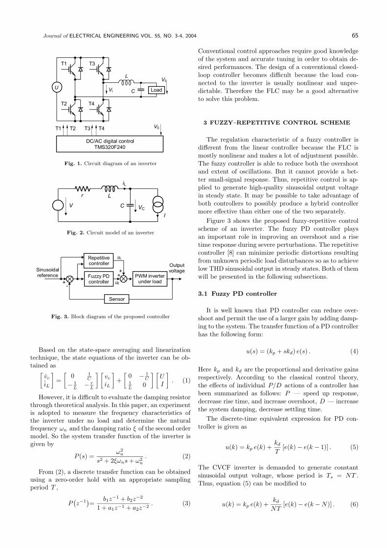
The circuit diagram of a single-phase full-bridge volt-age-source CVCF inverter is shown in Fig. 1. Since theswitching frequency is much higher than the natural fre-quency and modulation frequency, the dynamics of in-verter are mainly determined by its LC filter. Dead-timeeffect and inevitable loss in every part of the inverter of-fered a little damping. The damping effect can be summa-rized as a small resistor connected in series with the filterinductor. Figure 2 shows the circuit model of an inverter.The current source denotes the load current, which canbe considered as a disturbance.
∗ School of Electrical Power & Electronics Engineering, Huazhong University of Science & Technology, Hubei Wuhan, 430074, P.R.
China, E-mail: [email protected]
ISSN 1335-3632 c© 2004 FEI STU
Journal of ELECTRICAL ENGINEERING VOL. 55, NO. 3-4, 2004 65
DC/AC digital controlTMS320F240
LoadC
V0
Vi
L
T1 T4T3T2 V0
T1
T2
T3
T4
U
Fig. 1. Circuit diagram of an inverter
VC
I
L
V C
iL
r
Fig. 2. Circuit model of an inverter
uf
Repetitivecontroller
Sinusoidalreference
Outputvoltage
Fuzzy PDcontroller
ur
PWM inverterunder load
Sensor
+
++
-
Fig. 3. Block diagram of the proposed controller
Based on the state-space averaging and linearizationtechnique, the state equations of the inverter can be ob-tained as
[
vc
iL
]
=
[
0 1
C
−1
L−
rL
] [
vc
iL
]
+
[
0 −1
C1
L0
] [
UI
]
. (1)
However, it is difficult to evaluate the damping resistorthrough theoretical analysis. In this paper, an experimentis adopted to measure the frequency characteristics ofthe inverter under no load and determine the naturalfrequency ωn and the damping ratio ξ of the second ordermodel. So the system transfer function of the inverter isgiven by
P (s) =ω2
n
s2 + 2ξωns + ω2n
. (2)
From (2), a discrete transfer function can be obtainedusing a zero-order hold with an appropriate samplingperiod T ,
P(
z−1)
=b1z
−1 + b2z−2
1 + a1z−1 + a2z−2. (3)
Conventional control approaches require good knowledgeof the system and accurate tuning in order to obtain de-sired performances. The design of a conventional closed-loop controller becomes difficult because the load con-nected to the inverter is usually nonlinear and unpre-dictable. Therefore the FLC may be a good alternativeto solve this problem.
3 FUZZY–REPETITIVE CONTROL SCHEME
The regulation characteristic of a fuzzy controller isdifferent from the linear controller because the FLC ismostly nonlinear and makes a lot of adjustment possible.The fuzzy controller is able to reduce both the overshootand extent of oscillations. But it cannot provide a bet-ter small-signal response. Thus, repetitive control is ap-plied to generate high-quality sinusoidal output voltagein steady state. It may be possible to take advantage ofboth controllers to possibly produce a hybrid controllermore effective than either one of the two separately.
Figure 3 shows the proposed fuzzy-repetitive controlscheme of an inverter. The fuzzy PD controller playsan important role in improving an overshoot and a risetime response during severe perturbations. The repetitivecontroller [8] can minimize periodic distortions resultingfrom unknown periodic load disturbances so as to achievelow THD sinusoidal output in steady states. Both of themwill be presented in the following subsections.
3.1 Fuzzy PD controller
It is well known that PD controller can reduce over-shoot and permit the use of a larger gain by adding damp-ing to the system. The transfer function of a PD controllerhas the following form:
u(s) = (kp + skd) e(s) . (4)
Here kp and kd are the proportional and derivative gainsrespectively. According to the classical control theory,the effects of individual P/D actions of a controller hasbeen summarized as follows: P — speed up response,decrease rise time, and increase overshoot, D — increasethe system damping, decrease settling time.
The discrete-time equivalent expression for PD con-troller is given as
u(k) = kp e(k) +kd
T[e(k) − e(k − 1)] . (5)
The CVCF inverter is demanded to generate constantsinusoidal output voltage, whose period is Ts = NT .Thus, equation (5) can be modified to
u(k) = kp e(k) +kd
NT[e(k) − e(k − N)] . (6)

66 D. Shan-Xu — K. Yong — C. Jian: AN ALGORITHM FOR THE OUTPUT WAVEFORM COMPENSATION OF SPWM . . .
Table 1. Fuzzy Tuning rules
ce(k)NB NM NS Z PS PM PB
NB B B B B B B BNM B B B B B S SNS B B B B S S S
e(k) Z S S S B S S SPS S S S B B B BPM S S S B B B BPB B B B B B B B
(a) kp
ce(k)NB NM NS Z PS PM PB
NB S S S S S S SNM S S S S S B BNS B B B S B B B
e(k) Z B B B B B B BPS B B B S B B BPM B B S S S S SPB S S S S S S S
(b) kd
Data base
Rule base
DefuzzifierFuzzifierRule
evaluator
e(k)
ce(k)
kp
kd
Fig. 4. Block diagram of the fuzzy logical controller
a) b)
NB NM NS Z PS PM PB
-0.66 -0.33 0 0.660.33 1-10
1
0 1
1S B
Fig. 5. Membership functions of fuzzy variables: (a) e(k) andce(k) , (b) Kp and Kd
Obviously, the regulation of equation (6) is realizedperiod-by-period. It makes every sampling output trackcorresponding constant reference in a period.
However, the PD-type controller cannot yield a goodcontrol performance if the controlled object is highly non-linear and uncertain.
The main improvement of fuzzy PD controller is in en-dowing the classical PD controller with a certain adaptivecontrol capability. The parameters of the PD controllerkp and kd are determined based on the error e(k) andthe change of error ce(k) = e(k) − e(k − N) . The newfuzzy PD controller thus preserves the simple linear struc-ture of the conventional PD controller yet enhances itsself-tuning control capability. In this way system stabil-ity and a fast large-signal dynamic response with a smallovershoot can be achieved with proper handling of theproportional and derivative part as described hereafter.
Figure 4 shows a block diagram of fuzzy logical con-troller [9, 10]. The fuzzy PD controller is used to com-pensate for the voltage oscillation of the inverter due tosudden load changes.
Fuzzification converts crisp data into fuzzy sets, mak-ing it comfortable with the fuzzy set representation of thestate variable in the rule. In the fuzzification process, nor-malization by reforming a scale transformation is neededat first, which maps the physical values of the state vari-able into a normalized universe of discourse. The universeof discourse for error and change of error may be adjustedfrom open loop simulations. In the paper, the member-ship functions of these fuzzy sets for e(k) , ce(k) , kp andkd are shown in Fig. 5, respectively.
The tuning rules are given in Table 1. The propor-tional and derivative gains are initially calculated usingZiegler-Nichols tuning formula. For designing the control-rule base for tuning kp and kd , the following importantfactors have been taken into account:
(1) For large values of e(k) , a larger kp and a smallerkd are required.
(2) For small positive/negative values of e(k) and largece(k) (same sign), the system is diverging away from theequilibrium point. Therefore, a larger kp and a smallerkd are required.
(3) For small positive/negative values of e(k) and largece(k) (different sign), the system is converging toward theequilibrium point. Therefore, a smaller kp and a largerkd are required to prevent the system from oscillatingfurther.
(4) For small/zero values of e(k)and large ce(k) , thesystem is near the equilibrium point. Therefore, the con-troller should operate with the nominal values of thegains. Fig. 6 shows the control surface of fuzzy PD con-troller.
The inference method employs MAX-MIN method.The output membership function of each rule is given byminimum operator, whereas the combined fuzzy outputis given by maximum operator.
The imprecise fuzzy control action generated from theinference must be transformed to a precise control actionin real application. The center of mass (COM) method isused to defuzzify the fuzzy variables in the paper.
Output denormalization maps the normalized value ofthe control output variable into physical domain.
It is well known that fuzzy PD controller cannot pro-vide better small-signal response. Thus, repetitive con-troller is used to get low THD in the steady state.

Journal of ELECTRICAL ENGINEERING VOL. 55, NO. 3-4, 2004 67
(a) (b)
Fig. 6. Control surface of fuzzy PD controller: (a) Kp , and (b) Kd
r(k) e(k) y(k)
d(k)
Q(z-1
)z-N
Z-N
P(z-1
)S(z-1
)++
++
-+
- +
Fig. 7. Block diagram of repetitive control system
R(z-1
) +
E(z-1
)
z-N
[Q(z-1
) - P(z-1
)S(z-1
)]
1-P(z-1
) 1-Q(z-1
)z-N
D(z-1
)
+
++
Fig. 8. Block diagram representation of the error
S(z-1
)
krS1(z-1
) S2(z-1
)zk
Fig. 9. Block diagram of the compensation
3.2 Repetitive controller
The main drawback of SPWM inverter is large THD
with nonlinear loads such as rectifier and triac loads. The
nonlinear load causes a periodic disturbance. Repetitive
control provides an alternative to minimize periodic error
occurred in a dynamic system.
Repetitive control is based on the internal model prin-
ciple. The internal model principle means that the con-
trolled output tracks a set of reference commands without
a steady-state error if the generator for the references is
included in the stable closed-loop system. Repetitive con-
trol can be regarded as a simple learning control because
the control input is calculated using the information ofthe error signal in the preceding periods.
Figure 7 shows a block diagram of a plug-in type repet-itive control system. The repetitive controller calculatescorrection component from output voltage error. Thenthe correction component is added to the original sinu-soidal reference to achieve waveform correction.
The transfer function from the disturbance input d(k)to the tracking error e(k) is
F(
z−1)
=E(z−1)
D(z−1)=
1 − Q(z−1)z−N
1 − [Q(z−1) − S(z−1)P (z−1)]z−N.
(7)
If Q(
z−1)
= 1 and P(
z−1)
is stable, the correspondingfrequency function is
F(
ejωT)
=1 − e−jωNT
1 − [1 − S(ejωT )P (ejωT )]e−jωNT. (8)
The reference command is a sinusoidal signal with periodTs = NT . If d(k) is a periodic disturbance with the sameperiod, it can be expressed as Fourier series whose angularfrequency is ω = 2πm/NT (m = 0, 1, 2, . . . ). Thus, ifω = 2πm/NT (m = 0, 1, 2, . . . , N/2),
F(
ejωT)
=1 − e−j2πm
1 − [1 − S(ejωT )P (ejωT )]e−j2πm= 0 (9)
It means that no steady-state error is obtained withthe repetitive control for any periodic disturbance whosefrequency is less than Nyquist frequency π/T .
The core of the repetitive controller is the modifiedinternal model 1
/(
1−Q(z−1)z−N)
. Usually Q(
z−1)
is aclose-to-unit constant, typically 0.95. It relieves the strin-gent requirement of the repetitive controller to eliminateperiodic error completely.
Applying the small gain theorem to the feedback loopof error system in Fig. 8, a sufficient condition for stabilitycan be obtained,
∣
∣Q(
ejωT)
−S(
ejωT)
P(
ejωT∣
∣ < 1 , ω ∈ [0, π/T ] . (10)

68 D. Shan-Xu — K. Yong — C. Jian: AN ALGORITHM FOR THE OUTPUT WAVEFORM COMPENSATION OF SPWM . . .
200
400
0
-400
-200
0.035 0.036 0.037 0.038 0.039 0.040
(a)
200
400
0
-400
-200
0.035 0.036 0.037 0.038 0.039 0.040
(b)
200
400
0
-400
-200
0.035 0.036 0.037 0.038 0.039 0.040
(d)
200
400
0
-400
-200
(c)
0.035 0.036 0.037 0.038 0.039 0.040
0.026 0.028 0.030 0.032 0.034
(e)
200
400
0
-400
-200
200
400
0
-400
-200
(f)
0.026 0.028 0.030 0.032 0.034
Fig. 10. Simulation results of repetitive control inverter, (a) no load, (b) resistive load, (c) inductive load, (d) rectifier load, (e) full loadapplication, (f) full load removal
200
400
0
-400
-200
0.026 0.028 0.030 0.032 0.034
(a)
200
400
0
-400
-200
(b)
0.026 0.028 0.030 0.032 0.034
Fig. 11. Simulation results of fuzzy-repetitive control inverter, (a) full load application, (b) full load removal
In order to ensure stability and realize satisfactoryharmonic rejection
∣
∣Q(
ejωT)
−S(
ejωT)
P(
ejωT)∣
∣ shouldbe kept close to zero. With the limited system bandwidth,it is impossible to eliminate all harmonics completely.So the repetitive controller is synthesizing to minimizelow-order harmonic distortion. Figure 9 shows a blockdiagram of the compensator S
(
z−1)
.
To ensure stable operation at different load conditions,compensator design must be carried out at no load, whenthe resonant peak of the inverter is the highest. The mov-ing average filter S1
(
z−1)
and second order filter S2
(
z−1)
are used to achieve asymptotic stability by attenuatingthe resonant peak resulting from the inverter.
S1
(
z−1)
=γp(z
−p + zp) + γp−1(z−(p − 1) + zp−1) + · · · + γ0
2γp + 2γp−1 + · · · + γ0
(γ0 > . . . γp−1 > γp) (11)
S2
(
z−1)
=az−1 + bz−2
1 + cz−1 + dz−2(12)
Table 2. Parameters of the inverter
Item Nominal ValueDC link voltage 400 VOutput voltage 230 V
Output frequency 400 HzSwitching frequency 10 kHz
Sampling period 100 usFilter inductor 440 uHFilter capacitor 20 uF
Filter natural frequency 1.7 kHz
The magnitude of P(
z−1)
S1
(
z−1)
S2
(
z−1)
should beequal to unit at lower frequency and be decreased signif-icantly at higher frequency.
The time advance unit zk compensates for the corre-sponding phase delay resulting from P
(
z−1)
and
S1
(
z−1)
S2
(
z−1)
. The period delay unit z−N postponesthe error correction by one period so that it is possible torealize the time advance phase cancellation. So the sys-

Journal of ELECTRICAL ENGINEERING VOL. 55, NO. 3-4, 2004 69
V0
Ref.A : 2V, 500ms
I0
Ref.B : 2V, 500ms
Harmonic magnitude as a % of the fundamental amplitude
(%)
0.0
0.7
0.9
1.0
1.1
1.3
1.4
0.3
0.4
0.6
0.1
10 3020 40 500
(a)
THD=2.27%
(b)
Harmonic magnitude as a % of the fundamental amplitude
0.0
0.9
1.0
1.2
1.4
1.5
1.7
0.3
0.5
0.7
0.2
10 3020 40 500
THD=3.17%
I0
Ref.A : 2V, 500ms Ref.B : 2V, 500ms
V0
(c)
I0
V0
Ref.A : 2V, 500ms Ref.B : 2V, 500ms
Harmonic magnitude as a % of the fundamental amplitude
0.0
0.5
0.7
0.8
0.9
1.0
1.1
0.2
0.3
0.4
0.1
10 3020 40 500
THD=2.22%
I0
Ref.A : 2V, 500ms Ref.B : 2V, 500ms
V0
(d)
Harmonic magnitude as a % of the fundamental amplitude
0.0
1.1
1.3
1.5
1.7
1.9
2.2
0.4
0.6
0.9
0.2
10 3020 40 500
THD=3.5%
(%) (%)(%)
Fig. 12. Experimental waveforms of the proposed control inverter, (a) no load, (b) resistive load, (c) inductive load (I0 = 26A, cosφ = 08)(d) rectifier load,
V0
I0
Ref.A : 5V, 5ms Ref.B : 5V, 5ms
(a)
A
B
V0
I0
Ref.A : 5V, 5ms Ref.B : 5V, 5ms
(b)
A
B
Fig. 13. Simulation results of fuzzy-repetitive control inverter, (a) repetitive controll, (b) fuzzy-repetitive controll
tem possesses a nearly zero-phase-shift characteristic inthe medium and low frequency range.
The gain Kr is kept below one for stability. A smallerKr means enlarged stability margin, but a higher Kr
brings faster error convergence and smaller steady-stateerror.
Carefully selecting the controller parameters is a com-promise between the convergent rate and relative stabilityof the repetitive control system.
4 SIMULATION AND
EXPERIMENTAL RESULTS
To verify the effectiveness of the proposed controller, a400 Hz, 5.5 kW inverter is constructed and the proposedalgorithm is tested. The power circuit parameters of theinverter are shown in Table. 2. Gating signals for theinverter are obtained using the unipolar PWM method,which is the comparison-based method between a singletriangular carrier wave and two modulation voltage sig-nals with an opposite phase each other.
The model for the inverter with no load can be ob-tained as
P(
z−1)
=0.4801z−1 + 0.4438z−2
1 − 0.8728z−1 + 0.7967z−2. (13)
Suppose Q = 0.95, N = 25, every part of the compen-sator can be designed as
S1
(
z−1)
=z + 2 + z−1
4, (14)
S2
(
z−1)
=0.3382z−1 + 0.1517z−2
1 − 0.6016z−1 + 0.0915z−2, (15)
zk = z3 , (16)
Kr = 0.2 . (17)
The simulation of the inverter under fuzzy-repetitivecontrol is obtained by MATLAB.
Figure 10 shows the simulation results of the repetitivecontrol inverter for various load condition. It is obviouslythat the repetitive controller has good steady-state char-acteristics. However, it is not suitable for the applicationswith sudden load change due to their open-loop mannerin the first cycle of load change.
Figure 11 shows the dynamic response of the fuzzy-repetitive control inverter for a 100% step change in theload. From the simulations, the voltage in the transientresponse has significant improvement. The figure showsthat the system exhibits very fast dynamic response withexcellent load voltage regulation, indicating that the con-trol scheme ensures a “stiff” load voltage.

70 D. Shan-Xu — K. Yong — C. Jian: AN ALGORITHM FOR THE OUTPUT WAVEFORM COMPENSATION OF SPWM . . .
A single-chip DSP TMS320F240 provided by TexasInstruments is used to implement the proposed controlscheme. The software approach is adopted to realizefuzzy-repetitive control algorithm. The fuzzy decision ta-ble is computed off-line using MATLAB. Then it is storedin the Flash EEPROM of DSP. The fuzzy tuning processis performed on a lookup table. So it can be executed veryquickly.
Figure 12 shows the experimental results for variousload condition with fuzzy-repetitive control. The nonlin-ear load was chosen as a bridge rectifier with an outputLC filter (L = 1 mH, C = 2200 uF) and a resistive load(R = 20Ω). As in Fig. 10, the distortion of the outputvoltage is very small.
Figure 13 shows the transient response due to suddenchanges in the load. It can be observed that it takes about10 cycles with conventional repetitive controller, whereasit takes only about 4 cycles with proposed controller forthe settling of the step-changed load.
5 CONCLUSION
This paper describes a novel fuzzy-repetitive controlscheme for CVCF inverter applications. The proposedscheme combines a fuzzy PD controller with a repetitivecontroller. The control scheme improves both accuracy ofsteady state response and convergent rate of transient re-sponse. It is implemented using a TI TMS320F240 DSP.Simulation and experimental results show that the pro-posed control scheme is capable of supplying both linearand nonlinear loads with excellent voltage regulation andminimum distortion in the load voltage.
Acknowledgement
Project Supported by the National Natural ScienceFoundation of China 50007004, 50237023.
References
[1] ZIOGAS, P. D. : Optimum Voltage and Harmonic Control
PWM Techniques for Three-Phase inverters, IEEE Trans. Ind.
Applica. IA-16 No. 4 (1980), 542–546.
[2] ZIOGAS, P. D. : Application of Current Source Inverters in UPS
Systems, IEEE Trans. Ind. Applica. 25 No. 3 (1989), 408–418.
[3] TOSHIMASA HANEYOSHI—ATSUO KAWAMURA—HOFT,
R. G. : Waveform Compensation of PWM Inverter with Cyclic
Fluctuating Loads, IEEE Trans. Power. Electron. 24 No. 4
(1988), 582–589.
[4] KAWAMURA, A. : Instantaneous Feedback Controlled PWM
Inverter with Adaptive Hysteresis, IEEE Trans. Ind. Applica.
(1984), 769–775.
[5] BYRNES, C. I.—ISIDORI, A. : Output Regulation of Nonlinear
System: An Overview, International Journal Robust Nonlinear
Control 10 No. 5 (2000), 323–337.
[6] NIKIFOROV, V. O. : Adaptive Non-Linear Tracking with Com-
plete Compensation of Unknown Disturbance, European Journal
of Control 4 No. 2 (1998), 132–139.
[7] ISIDORI, A. : A Remark on the Problem of Semigloblal Nonlin-
ear Output Regulation, IEEE Transactions on Automatic Con-
trol 42 No. 12 (1997), 1734–1738.
[8] ZHANG KAI—KANG YONG—XIONG JIAN—ZHANG HUI
—CHEN JIAN : Repetitive Waveform Correction Technique for
CVCF-SPWM Inverters, IEEE PESC Conf. Rec., 2000.
[9] MATTAVELLI, P.—ROSSETTO, L.—SPIAZZI, G.—TENTI,
P. : General-Purpose Fuzzy Controller for DC-DC Converters,
IEEE Trans. Power. Electron. 12 No. 1 (1997), 79–86.
[10] CUPERTINO, F.—LATTANZI, A.—SALVATORE, L. : A
New Fuzzy Logic-Based Controller Design Method for DC and
AC Impressed-Voltage Drives, IEEE Trans. Power. Electron. 15
No. 6 (2000), 974–982.
Received 27 August 2003
Duan Shanxu was born in PR China on September 15,1970. He received the bachelor, master, PhD degrees, all inpower electronics and electrical drives, from Huazhong Uni-versity of Science & Technology, China in 1991, 1994 and 1999,respectively. Since 1999, he has been with the School of Elec-trical Power & Electronics Engineering, Huazhong Universityof Science & Technology, where he is currently associate pro-fessor. His main research interests include stabilization, non-linear control with application to power electronic circuit andsystem, full-digitalized control technique for power electron-ics apparatus and system, optimal control theory and corre-sponding applying techniques for high frequency PWM powerconverters.
Kang Yong was born in PR China on October 16, 1965.He received the bachelor, master, PhD degrees, all in powerelectronics and electrical drives, from the Huazhong Univer-sity of Science & Technology, China in 1988, 1991 and 1994,respectively. Since 1999, he has been with School of ElectricalPower & Electronics Engineering, Huazhong University of Sci-ence & Technology, where he is currently professor and tutorof PhD candidates. His main research interests include controltheory and application of complex system in power electronics,full-digitalized control technique for power electronics appara-tus and system.
Chen Jian (Senior member IEEE), was born in Wuhan,China, on August 27, 1935. He received the electrical engi-neering degree from Zhengzhou Electrical Engineering School,Zhengzhou, China, in 1954 and the BE degree from theDepartment of Electrical Engineering, Huazhong Instituteof Technology, Wuhan, China, in 1958. He has worked inHuazhong Institute of Technology (now Huazhong Universityof Science and Technology) since 1958. He was promoted toa lecturer in 1963 and to associate professor in 1978. He hasstudied power electronics, microprocessors, and their applica-tions at the University of Toronto in Canada, as a VisitingScholar, from 1980 to 1982. In 1985, he became full profes-sor. He is an author of three textbooks and over 120 technicalpapers. His main research interests include various power elec-tronic converters, ac drives, and power electronics applicationsin electric power systems.