an effective 80 and 40 meter ssb/cw...
TRANSCRIPT
Jan/Feb 2005 3
85 Woody Farm RdHot Spring, NC [email protected]
An Effective 80 and40 Meter SSB/CW Receiver
By Dave Lyndon, AK4AA
Something old and something new in ahomebrew dual-band receiver.
There is no limit to the numberof possible architectures foramateur-band receivers. This is
yet another entry, an 80- and 40-meterSSB/CW receiver that uses moderntechnology (something new) to imple-ment a high-performance design in asmall package with its roots in the1950s and 60s (something old). In ad-dition, there’s something borrowed,too. Although relying heavily on ARRLHandbooks and personal experience,much of the circuitry was borrowedfrom others without embarrassment.(I only steal from the very best! Seethe references at the end of this ar-ticle for acknowledgements.) It has
noise-figure, dynamic-range, andintermodulation performance as goodas most high-quality commercial re-ceivers, and it’s better than many.
The receiver is kept as simple aspossible without sacrificing perfor-mance by foregoing optional bells andwhistles. However, it is not a weekendproject, nor a task for the faint-hearted. It will take some time andpatience to duplicate, but the resultwill be rewarding—and relatively in-expensive, too. New parts are readilyavailable from various sources on theInternet and can be purchased for lessthan $200. A well-endowed junk boxwill reduce that considerably. You willalso need some test equipment tomake various adjustments. My testbench is quite modest: an inexpensivedigital multimeter, a 20 kΩ/V analogmultimeter, an old Heathkit audio sig-
nal generator, an even-more-ancientHeathkit RF signal generator, a “bot-tom-of-the-line” frequency counter, avintage 20 MHz dual-channel oscillo-scope and a homebrew inductancemeter described in Reference 8. Youcan get through this project with lessequipment, but I found the scope andcounter invaluable. It’s amazing whatcan be accomplished with reasonablysimple tools.
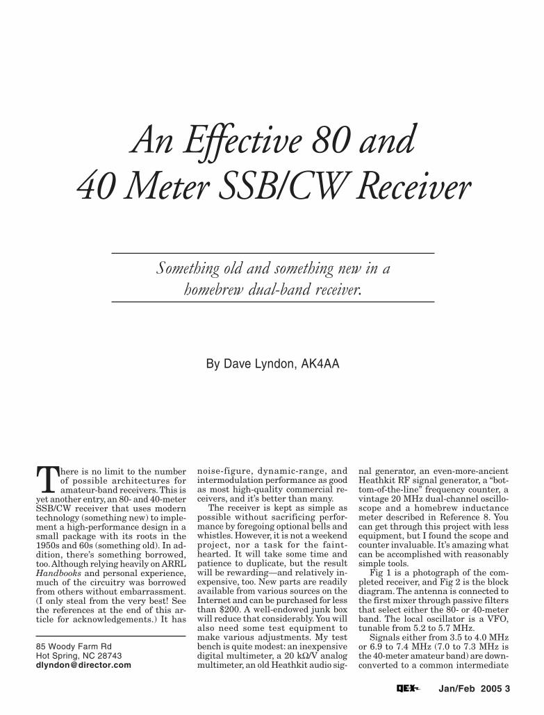
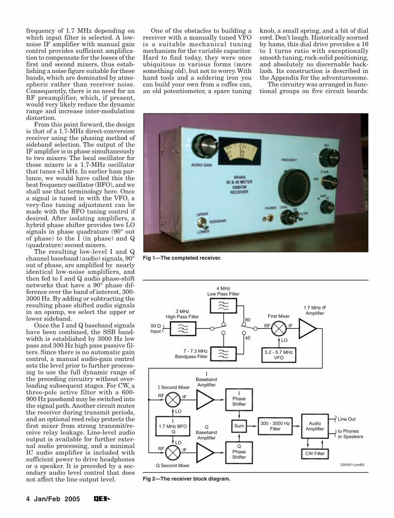
Fig 1 is a photograph of the com-pleted receiver, and Fig 2 is the blockdiagram. The antenna is connected tothe first mixer through passive filtersthat select either the 80- or 40-meterband. The local oscillator is a VFO,tunable from 5.2 to 5.7 MHz.
Signals either from 3.5 to 4.0 MHzor 6.9 to 7.4 MHz (7.0 to 7.3 MHz isthe 40-meter amateur band) are down-converted to a common intermediate
4 Jan/Feb 2005
frequency of 1.7 MHz depending onwhich input filter is selected. A low-noise IF amplifier with manual gaincontrol provides sufficient amplifica-tion to compensate for the losses of thefirst and second mixers, thus estab-lishing a noise figure suitable for thesebands, which are dominated by atmo-spheric rather than receiver noise.Consequently, there is no need for anRF preamplifier, which, if present,would very likely reduce the dynamicrange and increase inter-modulationdistortion.
From this point forward, the designis that of a 1.7-MHz direct-conversionreceiver using the phasing method ofsideband selection. The output of theIF amplifier is in phase simultaneouslyto two mixers. The local oscillator forthose mixers is a 1.7-MHz oscillatorthat tunes ±3 kHz. In earlier ham par-lance, we would have called this thebeat frequency oscillator (BFO), and weshall use that terminology here. Oncea signal is tuned in with the VFO, avery-fine tuning adjustment can bemade with the BFO tuning control ifdesired. After isolating amplifiers, ahybrid phase shifter provides two LOsignals in phase quadrature (90° outof phase) to the I (in phase) and Q(quadrature) second mixers.
The resulting low-level I and Qchannel baseband (audio) signals, 90°out of phase, are amplified by nearlyidentical low-noise amplifiers, andthen fed to I and Q audio phase-shiftnetworks that have a 90° phase dif-ference over the band of interest, 300-3000 Hz. By adding or subtracting theresulting phase shifted audio signalsin an opamp, we select the upper orlower sideband.
Once the I and Q baseband signalshave been combined, the SSB band-width is established by 3000 Hz lowpass and 300 Hz high pass passive fil-ters. Since there is no automatic gaincontrol, a manual audio-gain controlsets the level prior to further process-ing to use the full dynamic range ofthe preceding circuitry without over-loading subsequent stages. For CW, athree-pole active filter with a 600-900 Hz passband may be switched intothe signal path. Another circuit mutesthe receiver during transmit periods,and an optional reed relay protects thefirst mixer from strong transmit/re-ceive relay leakage. Line-level audiooutput is available for further exter-nal audio processing, and a minimalIC audio amplifier is included withsufficient power to drive headphonesor a speaker. It is preceded by a sec-ondary audio level control that doesnot affect the line output level.
Fig 1—The completed receiver.
Fig 2—The receiver block diagram.
One of the obstacles to building areceiver with a manually tuned VFOis a suitable mechanical tuningmechanism for the variable capacitor.Hard to find today, they were onceubiquitous in various forms (moresomething old), but not to worry. Withhand tools and a soldering iron youcan build your own from a coffee can,an old potentiometer, a spare tuning
knob, a small spring, and a bit of dialcord. Don’t laugh. Historically scornedby hams, this dial drive provides a 16to 1 turns ratio with exceptionallysmooth tuning, rock-solid positioning,and absolutely no discernable back-lash. Its construction is described inthe Appendix for the adventuresome.
The circuitry was arranged in func-tional groups on five circuit boards:
Jan/Feb 2005 5
(1) the RF/IF Board, (2) the OscillatorBoard in its own minibox, (3) theBaseband Amplifier Board, (4) thePhase Shifter/Filter Board, and (5) theAudio Board. Details of each boardand its associated chassis componentsfollow; you can look to the referencesfor further elaboration. Since there aremany toroidal inductors in the re-ceiver, you should read my suggestionson winding toroidal inductors withmagnet wire in the sidebar, “ToroidWinding Tips.”
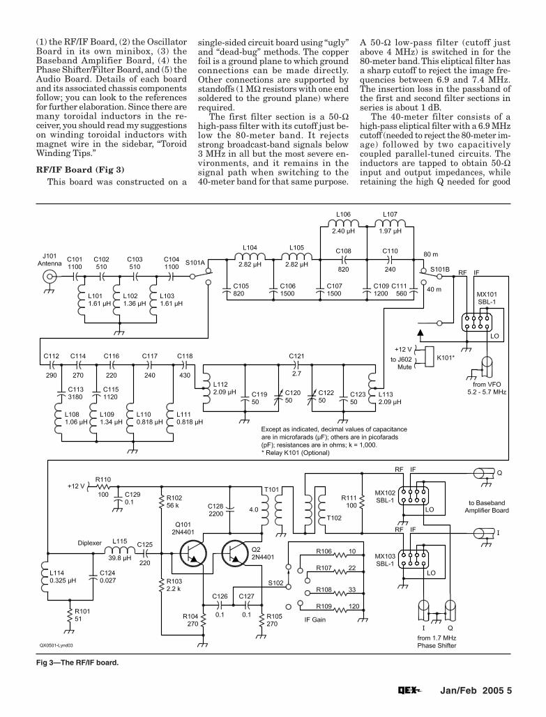
RF/IF Board (Fig 3)This board was constructed on a
Fig 3—The RF/IF board.
single-sided circuit board using “ugly”and “dead-bug” methods. The copperfoil is a ground plane to which groundconnections can be made directly.Other connections are supported bystandoffs (1 MΩ resistors with one endsoldered to the ground plane) whererequired.
The first filter section is a 50-Ωhigh-pass filter with its cutoff just be-low the 80-meter band. It rejectsstrong broadcast-band signals below3 MHz in all but the most severe en-vironments, and it remains in thesignal path when switching to the40-meter band for that same purpose.
A 50-Ω low-pass filter (cutoff justabove 4 MHz) is switched in for the80-meter band. This eliptical filter hasa sharp cutoff to reject the image fre-quencies between 6.9 and 7.4 MHz.The insertion loss in the passband ofthe first and second filter sections inseries is about 1 dB.
The 40-meter filter consists of ahigh-pass eliptical filter with a 6.9 MHzcutoff (needed to reject the 80-meter im-age) followed by two capacitivelycoupled parallel-tuned circuits. Theinductors are tapped to obtain 50-Ωinput and output impedances, whileretaining the high Q needed for good
6 Jan/Feb 2005
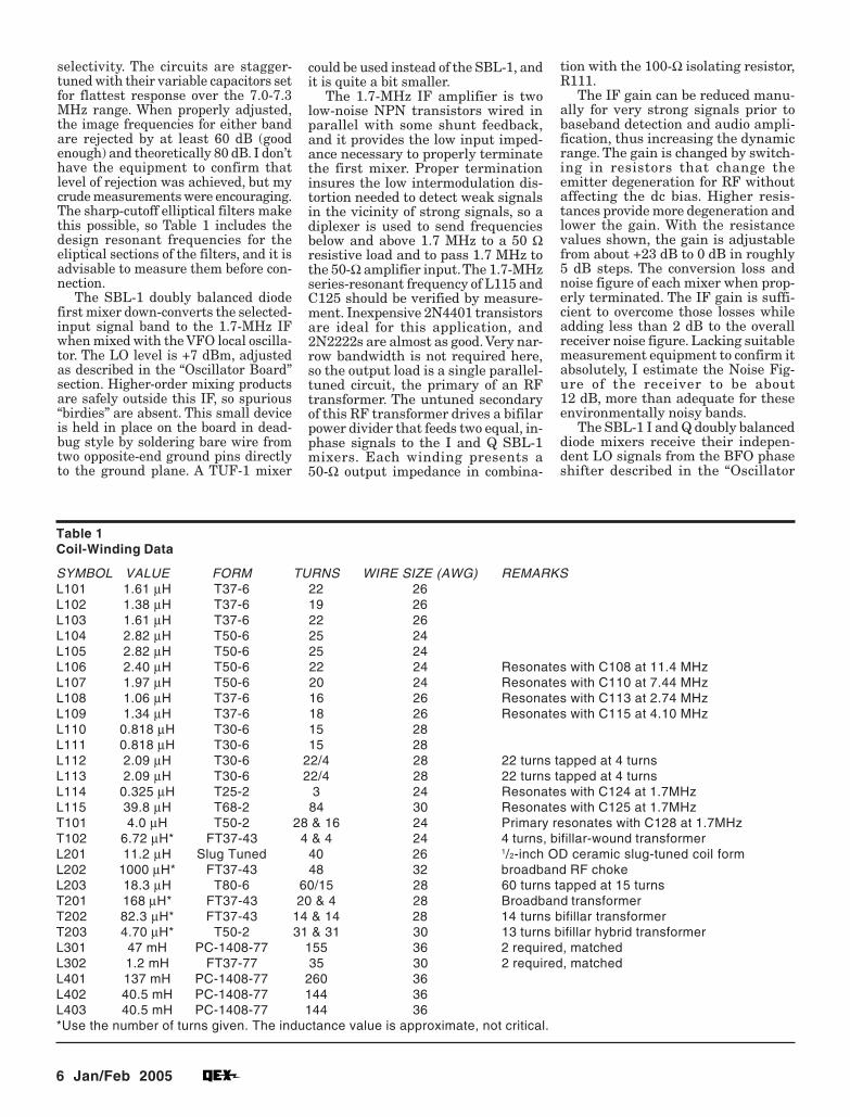
selectivity. The circuits are stagger-tuned with their variable capacitors setfor flattest response over the 7.0-7.3MHz range. When properly adjusted,the image frequencies for either bandare rejected by at least 60 dB (goodenough) and theoretically 80 dB. I don’thave the equipment to confirm thatlevel of rejection was achieved, but mycrude measurements were encouraging.The sharp-cutoff elliptical filters makethis possible, so Table 1 includes thedesign resonant frequencies for theeliptical sections of the filters, and it isadvisable to measure them before con-nection.
The SBL-1 doubly balanced diodefirst mixer down-converts the selected-input signal band to the 1.7-MHz IFwhen mixed with the VFO local oscilla-tor. The LO level is +7 dBm, adjustedas described in the “Oscillator Board”section. Higher-order mixing productsare safely outside this IF, so spurious“birdies” are absent. This small deviceis held in place on the board in dead-bug style by soldering bare wire fromtwo opposite-end ground pins directlyto the ground plane. A TUF-1 mixer
Table 1Coil-Winding Data
SYMBOL VALUE FORM TURNS WIRE SIZE (AWG) REMARKSL101 1.61 µH T37-6 22 26L102 1.38 µH T37-6 19 26L103 1.61 µH T37-6 22 26L104 2.82 µH T50-6 25 24L105 2.82 µH T50-6 25 24L106 2.40 µH T50-6 22 24 Resonates with C108 at 11.4 MHzL107 1.97 µH T50-6 20 24 Resonates with C110 at 7.44 MHzL108 1.06 µH T37-6 16 26 Resonates with C113 at 2.74 MHzL109 1.34 µH T37-6 18 26 Resonates with C115 at 4.10 MHzL110 0.818 µH T30-6 15 28L111 0.818 µH T30-6 15 28L112 2.09 µH T30-6 22/4 28 22 turns tapped at 4 turnsL113 2.09 µH T30-6 22/4 28 22 turns tapped at 4 turnsL114 0.325 µH T25-2 3 24 Resonates with C124 at 1.7MHzL115 39.8 µH T68-2 84 30 Resonates with C125 at 1.7MHzT101 4.0 µH T50-2 28 & 16 24 Primary resonates with C128 at 1.7MHzT102 6.72 µH* FT37-43 4 & 4 24 4 turns, bifillar-wound transformerL201 11.2 µH Slug Tuned 40 26 1/2-inch OD ceramic slug-tuned coil formL202 1000 µH* FT37-43 48 32 broadband RF chokeL203 18.3 µH T80-6 60/15 28 60 turns tapped at 15 turnsT201 168 µH* FT37-43 20 & 4 28 Broadband transformerT202 82.3 µH* FT37-43 14 & 14 28 14 turns bifillar transformerT203 4.70 µH* T50-2 31 & 31 30 13 turns bifillar hybrid transformerL301 47 mH PC-1408-77 155 36 2 required, matchedL302 1.2 mH FT37-77 35 30 2 required, matchedL401 137 mH PC-1408-77 260 36L402 40.5 mH PC-1408-77 144 36L403 40.5 mH PC-1408-77 144 36*Use the number of turns given. The inductance value is approximate, not critical.
could be used instead of the SBL-1, andit is quite a bit smaller.
The 1.7-MHz IF amplifier is twolow-noise NPN transistors wired inparallel with some shunt feedback,and it provides the low input imped-ance necessary to properly terminatethe first mixer. Proper terminationinsures the low intermodulation dis-tortion needed to detect weak signalsin the vicinity of strong signals, so adiplexer is used to send frequenciesbelow and above 1.7 MHz to a 50 Ωresistive load and to pass 1.7 MHz tothe 50-Ω amplifier input. The 1.7-MHzseries-resonant frequency of L115 andC125 should be verified by measure-ment. Inexpensive 2N4401 transistorsare ideal for this application, and2N2222s are almost as good. Very nar-row bandwidth is not required here,so the output load is a single parallel-tuned circuit, the primary of an RFtransformer. The untuned secondaryof this RF transformer drives a bifilarpower divider that feeds two equal, in-phase signals to the I and Q SBL-1mixers. Each winding presents a50-Ω output impedance in combina-
tion with the 100-Ω isolating resistor,R111.
The IF gain can be reduced manu-ally for very strong signals prior tobaseband detection and audio ampli-fication, thus increasing the dynamicrange. The gain is changed by switch-ing in resistors that change theemitter degeneration for RF withoutaffecting the dc bias. Higher resis-tances provide more degeneration andlower the gain. With the resistancevalues shown, the gain is adjustablefrom about +23 dB to 0 dB in roughly5 dB steps. The conversion loss andnoise figure of each mixer when prop-erly terminated. The IF gain is suffi-cient to overcome those losses whileadding less than 2 dB to the overallreceiver noise figure. Lacking suitablemeasurement equipment to confirm itabsolutely, I estimate the Noise Fig-ure of the receiver to be about12 dB, more than adequate for theseenvironmentally noisy bands.
The SBL-1 I and Q doubly balanceddiode mixers receive their indepen-dent LO signals from the BFO phaseshifter described in the “Oscillator
Jan/Feb 2005 7
Board” section. These levels, too, are+ 7 dBm for best performance. Thesedevices are held in place as dead-bugsalso by soldering bare wires from twoopposite-end ground pins directly tothe ground plane. The outputs of the Iand Q mixers are fed directly tomatched amplifiers on the BasebandAudio Board.
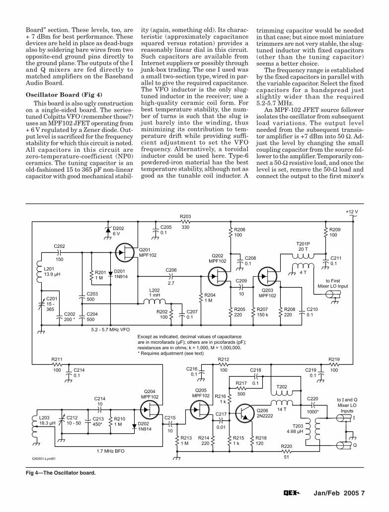
Oscillator Board (Fig 4)This board is also ugly construction
on a single-sided board. The series-tuned Colpitts VFO (remember those?)uses an MPF102 JFET operating from+ 6 V regulated by a Zener diode. Out-put level is sacrificed for the frequencystability for which this circuit is noted.All capacitors in this circuit arezero-temperature-coefficient (NP0)ceramics. The tuning capacitor is anold-fashioned 15 to 365 pF non-linearcapacitor with good mechanical stabil-
Fig 4—The Oscillator board.
ity (again, something old). Its charac-teristic (approximately capacitancesquared versus rotation) provides areasonably linear dial in this circuit.Such capacitors are available fromInternet suppliers or possibly throughjunk-box trading. The one I used wasa small two-section type, wired in par-allel to give the required capacitance.The VFO inductor is the only slug-tuned inductor in the receiver; use ahigh-quality ceramic coil form. Forbest temperature stability, the num-ber of turns is such that the slug isjust barely into the winding, thusminimizing its contribution to tem-perature drift while providing suffi-cient adjustment to set the VFOfrequency. Alternatively, a toroidalinductor could be used here. Type-6powdered-iron material has the besttemperature stability, although not asgood as the tunable coil inductor. A
trimming capacitor would be neededin that case; but since most miniaturetrimmers are not very stable, the slug-tuned inductor with fixed capacitors(other than the tuning capacitor)seems a better choice.
The frequency range is establishedby the fixed capacitors in parallel withthe variable capacitor. Select the fixedcapacitors for a bandspread justslightly wider than the required5.2-5.7 MHz.
An MPF-102 JFET source followerisolates the oscillator from subsequentload variations. The output levelneeded from the subsequent transis-tor amplifier is +7 dBm into 50 Ω. Ad-just the level by changing the smallcoupling capacitor from the source fol-lower to the amplifier. Temporarily con-nect a 50-Ω resistive load, and once thelevel is set, remove the 50-Ω load andconnect the output to the first mixer’s

8 Jan/Feb 2005
Fig 5—The baseband (audio) board.
LO terminal. Lacking a power meter, Iadjusted the level to 1.4 V P-P with abroadband oscilloscope (1.4 V P-P=0.7 VPk = 0.49 VRMS = 4.8 mW into 50 Ω= +6.9 dBm.) The frequency variationfrom cold start to operating tempera-ture in 70° F ambient was less than500 Hz in the first half hour. After that,it was less than 50 Hz over a consider-able period. Long contacts will not re-quire retuning. That’s not too bad formostly junk-box parts!
The 1.7-MHz BFO is a conventionalHartley oscillator also using an MPF-102 JFET operating from the +6 VZener. In this case, a type-6-materialtoroid is suitable. (The 1.7-MHz fre-quency is a smidge lower than recom-mended for high Q.) It is held securelyin place upright by a plastic tie-wrapinserted through a small hole in thecircuit board, looped through the tor-
oid, routed back through the hole, andpulled taught through the locking slotof the tie-wrap. At 1.7 MHz, the fre-quency drift is as good as the VFO andtends to be in the opposite direction.The total drift is quite acceptable forboth SSB and CW. Again, NP0 ceramiccapacitors were used throughout, ex-cept for a small front-panel-mountedvariable capacitor, C212, that is con-nected to the oscillator tank via a min-iature shielded coaxial cable. Thecapacitance of the cable, 10 pF or sofor about 4 inches, becomes a part ofthe tuned circuit, so it must be stable.I used a short length of one of the twosmall 72-Ω coax cables in an S-videocable. With the variable capacitor atits center position, the BFO center fre-quency is set to 1.7 MHz by selectingfixed NP0 capacitors and a small trim-mer included for final adjustment. At
this lower frequency, it is stableenough. The approximate valuesshown provided front-panel tuning of±3 kHz after removing a couple of ro-tator plates from the capacitor I hadon hand to get the required range.
The oscillator is followed by a JFETsource follower for load isolation thenan NPN transistor amplifier. The am-plifier is a widely used low-output-impedance broadband circuit. Its gainis established by the ratio of resistorsR217 and R216; the former is bypassedfor RF, the latter is not. A larger R216reduces RF feedback and increases thegain; a smaller R216 increases the RFfeedback and lowers the gain. The to-tal series resistance of R217 and R216must be kept the same to properly biasthe transistor. We need about +10 dBmof output (2.0 VP-P on the oscilloscopefeeding a temporary 50-Ω resistor) to

Jan/Feb 2005 9
Fig 6 (Right) —The phase shifter/filterboard.
provide +7 dBm LO signals out of thehybrid phase shifter to each of the twobaseband mixers, and the componentvalues shown should yield that resultapproximately.
A twisted-wire hybrid phase shifter,described in Reference 4, was used todivide the +10 dBm signal into two+7 dBm signals in phase quadrature.There are several possible RF phase-shift networks; but this circuit, whileanalytically mysterious, is simple toconstruct and requires no adjustmentover a wide frequency range. This vari-ant uses a single capacitor rather thantwo but is electrically equivalent to theoriginal described in the reference.Precise 90° phase shift can be achievedby adjustment of the capacitance asdescribed below. Its output levelschange with frequency but remain 90°apart to enable excellent sideband re-jection. With the values shown, the twooutputs near 1.7 MHz will be nearlyequal, about +7 dBm (1.4 VP-P) whenterminated with individual 50-Ω re-sistors. Once the levels are set by ad-justing the gain of the amplifier,remove the terminating resistors andconnect the outputs to the I and Qbaseband mixers’ LO terminals.
Baseband Audio Board (Fig 5)This is the third ugly construction
board. This board and part of the fol-lowing board are stolen from the ex-cellent designs of Glen Leinweber,VE3DNL, noted in Reference 4. Muchof this work was based on the earlierwork of Rick Campbell, KK7B, as citedin the references.
As Campbell and Leinweber haveso eloquently informed us, the I andQ mixers must be properly terminatedat all frequencies to provide the de-sired performance. For this purpose weuse a diplexer that routes signals be-low 300 Hz and above 3000 Hz to a50-Ω terminating resistor, while sig-nals of interest are sent to an audioamplifier with 50-Ω input impedance.We need a lot of low-noise audio gainbecause the weakest signals from theI and Q mixers will be in the micro-volt range. Furthermore, the diplexersand audio amplifiers in the I and Qchannels must match each other asclosely as possible to achieve good un-wanted-sideband rejection. For thatreason, we use 1%-matched compo-nents in the two channels. We can com-pensate for minor gain imbalancedownstream, but phase-shift balanceof 1° or better is required for good side-band rejection.
10 Jan/Feb 2005
On the advice of Leinweber, I usedPC1408-77 pot cores available fromAmidon to get high inductance withreasonable Q. Careful attention toequal turns count and equal plasticmounting-screw pressure will yieldthe desired result. Be careful not toover tighten the hardware because thecores are fragile, as I discovered to myregret. The exact inductance value isless important than is matching (equalvalues). If suitable test equipment isavailable, the inductor values shouldbe measured. The most phase-criticalcomponents in the diplexers, however,are the series-tuned LC circuits thatpass the audio frequencies to the am-plifiers. You can check the amplifiers’phase shift by driving both channelswith the same 1000-Hz audio signalat the diplexer inputs and observingthe sum of the amplifier outputs on adual-channel scope, with one channelinverted and the scope channel gainsadjusted for the best null. Then checkfor nulls at 300 Hz and 3000 Hz withthe same signal connected to both in-puts. If there is not a good null at bothfrequencies, there is a phase differencein the channels, and it is more thanlikely caused by imbalance in thediplexers. In that case, you must ad-just the inductance, capacitance orboth in one channel or the other. Thephase shift at 300 Hz is affectedmostly by the series capacitance, soadding capacitance to one channel orthe other will improve the low-fre-quency null. Similarly, the series in-ductor will dominate the phase shiftat 3000 Hz, and it may be necessaryto unwind a few turns on one induc-tor or the other to get a good high-fre-quency null. A final check using aLissajous pattern (if your scope is soendowed) will show a straight line at45° with no ellipticity (separation)over the audio range.
Phase Shifter/Filter Board (Fig 6)This board and the Audio Board are
built on prefabricated integrated-circuitexperimental boards. Sockets were usedfor the integrated circuits although thedevices could be soldered in directly atthe risk of damaging them. Perfboardmay even be preferable because thepads on prefab circuit boards are diffi-cult to solder and may lift off. For theambitious, a custom printed circuitboard could be developed. Perhaps Iwould do that (for all the boards) if thereis sufficient interest.
The I and Q audio phase shiftersare implemented with quad low-noiseop amps. The theory of operation isbeyond the scope of this article; butwith careful adjustment, the receiver
is capable of at least 40 dB of un-wanted sideband rejection. With extracare and patience 50 dB is possible,and 60 dB can be achieved with real-izable components.
It is important to use stable 1%-tol-erance capacitors in this network, andseveral types are available. I usedpolystyrene capacitors, although theyare pricey and undesirably large.Trimming resistors in the Q networkare used to finely adjust the phaseshift. Leinweber describes a methodfor adjusting these trimmers using ahomebrew quadrature square-waveoscillator; I shall suggest a simplermethod below.
The entire receiver operates froma single +12-V power supply, but theop amps require both positive andnegative supply voltages. To avoid thecomplexity and expense of dual powersupplies, an artificial signal commonis established +6 V above chassisground using a “stiff” voltage divider.Thus, voltages +6 V above and -6 Vbelow the signal common potential areestablished.
Outputs of the I and Q phaseshifters are summed in an op amp toreject one sideband. By switching theQ output to the non-inverting input—in effect shifting its phase 180°—theopposite sideband is rejected. The re-
sulting SSB signal is then filtered bya 500-Ω passive network consisting ofa five-pole 3000-Hz low-pass filter anda three-pole 300-Hz high-pass filterimplemented with pot-core inductorsand stable capacitors. A 500-Ω poten-tiometer terminates the network andis the audio gain control.
Adjustment requires a pair of au-dio signals in phase quadrature at3400, 715, and 295 Hz, in turn. TheLeinweber method uses a homebrewcircuit to create these signals assquare waves (see Reference 4), butharmonic filtering is required to ob-serve the fundamental only. Anothermethod is to use the front end of thereceiver itself to generate the quadra-ture audio signals. I found that bothmethods give nearly the same result.It relies on the 1.7 MHz hybrid phaseshifter’s correct LO phase relation-ships, so initially we must trust in thatcircuit’s performance prior to finaladjustment.
Insert a low-level 80-meter signalfrom an RF signal generator or testoscillator at the antenna input. Whilemonitoring the signal at the audio-gaincontrol with the scope, tune the re-ceiver to obtain an audio output. Thataudio frequency can be measured witha frequency counter or by comparisonwith an accurate audio oscillator us-
Toroid Winding TipsThe enamel must be removed from the wire, of course, for solder connec-
tions where required, either chemically or by scraping with a sharp knife. I pre-fer the latter method. For mechanical stability I recommend that the first andlast turn on each inductor be “tucked under” itself and pulled taught, taking carenot to damage the enamel, which would short the turn. The inductance of thesetoroids can be adjusted over a range of ±5% or so by spreading or compress-ing the turns. The number of turns and their spacing is more important thanthe wire size, so one should generally use the largest wire that will fit comfort-ably on the core and allow for some adjustment. For maximum Q, the windingshould cover only about 3/4 of the core circumference. Turns-versus-inductanceformulas for these toroids are approximations. It may be necessary to add orremove turns to achieve the desired inductance. I have found the formulasgenerally call for too many turns, so inductance measurement is required. Onemethod for doing this was described in my QEX article (Reference 8). For thebifilar windings specified, twist two lengths of magnet wire together with abouteight turns per inch. This insures that the two windings are closely coupled, ofthe same length and same number of turns. Once the inductance is correct,generously apply coil dope to prevent winding movement. Clear nail polishworks very well for this purpose. Table 1 provides the turns and wire sizesactually used for the inductors and RF transformers in the receiver.
The receiver uses several pot-core inductors, available from Amidon, for thehigher inductances values required in the audio circuits. Many turns (hun-dreds) of very fine magnet wire must be wound on the plastic bobbin providedwith the cores. That fine wire is fragile and difficult to connect externally. Bor-row a technique used in transformers: Strip and wind an inch or so of eachfine-wire end over the stripped end of a larger-diameter insulated wire, solderthe joint, coat the connection with coil dope (nail polish) for insulation and windthe last few coil turns with the larger wire, which seves as a lead for the trans-former. To prevent slippage of the winding, the final turn is “looped under” andpulled taught as is done for the toroids. Apply a coat of dope over the winding.
Jan/Feb 2005 11
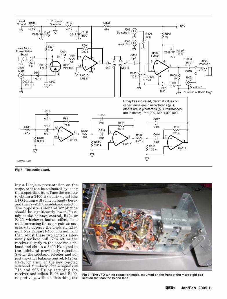
Fig 7—The audio board.
ing a Lisajous presentation on thescope, or it can be estimated by usingthe scope’s time base. Tune the receiverto obtain a 3400-Hz audio signal (theBFO tuning will come in handy here),and then switch the sideband selector.The opposite sideband amplitudeshould be significantly lower. First,adjust the balance control, R424 orR425, whichever has an effect, for anull, increasing the scope gain as nec-essary to observe the weak signal atnull. Next, adjust R406 for a null, andthen adjust these two controls alter-nately for best null. Now retune thereceiver slightly to the opposite side-band and obtain a 3400-Hz signal inthe sideband previously rejected.Switch the sideband selector and ad-just the other balance control, R425 orR424, for a null in the new rejectedsideband. Similarly, obtain signals at715 and 295 Hz by retuning thereceiver and adjust R406 and R409,respectively, without disturbing the
Fig 8—The VFO tuning capacitor inside, mounted on the front of the more-rigid boxsection that has the folded tabs.

12 Jan/Feb 2005
amplitude-balance controls. With gen-erous portions of care and patience, it-eration of these five adjustments willyield optimum performance.
If good nulls of approximately equalrejection cannot be obtained on bothupper and lower sidebands using thesum and difference balance adjust-ments only with common audio phaseshifter adjustments, the 1.7-MHz hy-brid phase shifter may not be provid-ing signals exactly 90° out of phase. Add(or subtract) a bit of capacitance toC 220 in increments of about 50 pF andtry again at 4300 Hz. When the hybrid’soutputs are in phase quadrature, itshould be possible to get both upper andlower sideband rejection of at least40 dB (100:1 voltage ratio between side-bands) with the same set of phase ad-justments in the audio phase shifter. Igot 46 dB without much trouble, and50 dB with a little patience.
Audio Board (Fig 7)Another stiff voltage divider is used
to establish an artificial signal commonat +6 V for this board’s op amps. Thesignal passes first through a JFET tran-sistor used to mute the receiver duringtransmit by grounding the cathode ofdiode D601 to bias the transistor off.The following stage is an op amp with26 dB gain to raise the signal to a linelevel suitable for external audio pro-cessing.
The three-pole band-pass active fil-ter may be switched into the signalpath for CW reception. It has a 3-dBbandwidth of 400 Hz centered on750 Hz. The resistor values were cho-sen such that all capacitors in the fil-ter are the same value, 0.01 µF. Theyneed not be this exact value, but theirvalues should match within 3% forbest filter performance. The non-stan-dard resistance values are series/parallel combinations of resistors asmeasured with a DMM. Notice thateach stage’s input signal is attenuated;these band-pass stages have consid-erable gain that must be compensatedto avoid downstream overload. Theoverall gain of the filter is about10 dB, and that provides a reasonablebalance of audible signal level whenswitching the narrow filter in and out.A secondary audio-gain control is pro-vided to set the level for the optionalIC headphone and speaker amplifierthat follows. This amplifier will alsoaccept an input for a CW sidetone ifdesired.
Power SupplyA single external +12 V source is re-
quired. It must supply about 100 mA,but if the on-board audio power ampli-
Fig 10—The RF/IF board is mounted outside the minibox on an L-shaped aluminumbracket attached to one end of the oscillator minibox.
Fig 9—The rotary dial drive outside the front of the more-rigid box section.
fier is used to drive a speaker, the cur-rent will peak to twice that value at fullvolume. Obviously, the receiver is wellsuited for field or emergency operationsince it can be operated from a 12 Vbattery.
Construction (Figs 8 through 11)The receiver is housed in a 5×10×3
inch aluminum chassis (Bud BPA-1591 or equivalent) with the 5×10 inchsurface as the front panel. A windowin the front panel allows viewing aportion of the rotary dial. Of course, amore exotic (and expensive) enclosurecould be used, and a bit more spacewould be a welcome luxury. Neverthe-less, this is a description of the receiver
as actually constructed.The phase shifter/filter board is
mounted inside the chassis on one endand the audio board on the bottom,both with ¼-inch standoff hardwareto hold the boards’ underside wiringoff the chassis. They are positioned toallow clearance for the minibox assem-bly described below. The SIDEBAND se-lector switch and the main AUDIO GAINcontrol are the front panel controlsassociated with the phase shifter/fil-ter board, and they are mounted onthe front panel near that board. Simi-larly, the headphone/speaker VOLUMEcontrol, the ungrounded speaker andheadphone jacks, and the CW filterswitch are mounted on the front panel

Jan/Feb 2005 13
near the audio board. These front-panel controls are wired to the boardsbefore mounting them inside the chas-sis, and they must be positioned toleave space for the rotary dial.
The oscillator board is mounted ina separate aluminum “minibox.”Figs 8 and 9 show the VFO tuning ca-pacitor inside and rotary dial driveoutside, mounted on the front of themore-rigid box section that has thefolded tabs. The box itself is secured¾ inch behind the receiver front panelto allow space for the rotary dial. Thedial driveshaft is long enough to passthrough a clearance hole in the frontpanel for fitting of the main tuningknob. Since the VFO frequency maybe affected slightly when the rearcover is installed, a hole in the coverprovides access to the VFO inductorfor final adjustment.
An L-shaped aluminum bracket at-taches to one end of the oscillatorminibox as shown in Fig 10, and theRF/IF board is mounted outside theminibox on this bracket with the samemounting screws. Small holes aredrilled through the board, bracket andminibox through which pass wiresfrom the oscillators to the mixers, tothe VFO via small coax and to theBFO with short insulated wires. Theoscillator board receives +12 Vthrough a small hole, bypassed with a0.1-µF capacitor at the entry point.The front face of the bracket supportsthe BFO tuning capacitor, the IF GAINswitch, and the band switch. A smallaluminum corner bracket at the topof the L-shaped bracket (as shown)attaches the baseband amplifier boardto the assembly.
Once wiring is completed, the as-sembly is mounted inside the largerchassis, and the hardware for the front-panel controls attaches the assemblyto the front panel. Another small alu-minum bracket attaches the oppositeend of the box to the bottom of the chas-sis for stability. The minibox assemblywill, with care and patience, fit insidethe larger chassis even though the ro-tary dial is slightly larger than theback opening and must be inserted atan angle until inside the chassis.
Because the receiver has more than100 dB of audio gain available, goodshielding, adequate power supplydecoupling and careful grounding arerequired to prevent feedback when allcontrols are set for maximum gain.Use high-quality shielded cable foraudio connections, and connectgrounds of the baseband amplifier,phase shifter, and audio boards onlyvia the shields of these cables. Theheadphone and speaker leads are
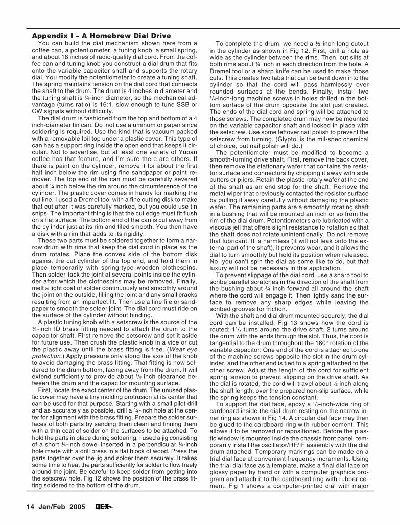
Fig 12—The position of the brass fitting soldered to the bottom of the dial-drive drum. A1/2-inch-long cutout in the cylinder completes the drum.
Fig 11—The receiver units prewired and tested together prior to mounting them insidethe chassis.
twisted-pair, grounded only at theaudio board, so insulated jacks are re-quired. Using only these groundconnections will avoid potentiallytroublesome ground loops and micro-phonics. The interconnecting cablesare intentionally made long so that theunits may be prewired and tested to-
gether prior to mounting them insidethe chassis, as shown in Fig 11.
Back-panel connectors are mountedon the lower lip of the chassis at therear. These are 12 V dc input, mutecontrol, line-level audio out, sidetonein, and speaker. When all wiring iscomplete, an optional back panel with
14 Jan/Feb 2005
Appendix I – A Homebrew Dial DriveYou can build the dial mechanism shown here from a
coffee can, a potentiometer, a tuning knob, a small spring,and about 18 inches of radio-quality dial cord. From the cof-fee can and tuning knob you construct a dial drum that fitsonto the variable capacitor shaft and supports the rotarydial. You modify the potentiometer to create a tuning shaft.The spring maintains tension on the dial cord that connectsthe shaft to the drum. The drum is 4 inches in diameter andthe tuning shaft is ¼-inch diameter, so the mechanical ad-vantage (turns ratio) is 16:1, slow enough to tune SSB orCW signals without difficulty.
The dial drum is fashioned from the top and bottom of a 4inch-diameter tin can. Do not use aluminum or paper sincesoldering is required. Use the kind that is vacuum packedwith a removable foil top under a plastic cover. This type ofcan has a support ring inside the open end that keeps it cir-cular. Not to advertise, but at least one variety of Yubancoffee has that feature, and I’m sure there are others. Ifthere is paint on the cylinder, remove it for about the firsthalf inch below the rim using fine sandpaper or paint re-mover. The top end of the can must be carefully severedabout ¼ inch below the rim around the circumference of thecylinder. The plastic cover comes in handy for marking thecut line. I used a Dremel tool with a fine cutting disk to makethat cut after it was carefully marked, but you could use tinsnips. The important thing is that the cut edge must fit flushon a flat surface. The bottom end of the can is cut away fromthe cylinder just at its rim and filed smooth. You then havea disk with a rim that adds to its rigidity.
These two parts must be soldered together to form a nar-row drum with rims that keep the dial cord in place as thedrum rotates. Place the convex side of the bottom diskagainst the cut cylinder of the top end, and hold them inplace temporarily with spring-type wooden clothespins.Then solder-tack the joint at several points inside the cylin-der after which the clothespins may be removed. Finally,melt a light coat of solder continuously and smoothly aroundthe joint on the outside, filling the joint and any small cracksresulting from an imperfect fit. Then use a fine file or sand-paper to smooth the solder joint. The dial cord must ride onthe surface of the cylinder without binding.
A plastic tuning knob with a setscrew is the source of the¼-inch ID brass fitting needed to attach the drum to thecapacitor shaft. First remove the setscrew and set it asidefor future use. Then crush the plastic knob in a vice or cutthe plastic away until the brass fitting is free. (Wear eyeprotection.) Apply pressure only along the axis of the knobto avoid damaging the brass fitting. That fitting is now sol-dered to the drum bottom, facing away from the drum. It willextend sufficiently to provide about 1/8 inch clearance be-tween the drum and the capacitor mounting surface.
First, locate the exact center of the drum. The unused plas-tic cover may have a tiny molding protrusion at its center thatcan be used for that purpose. Starting with a small pilot drilland as accurately as possible, drill a ¼-inch hole at the cen-ter for alignment with the brass fitting. Prepare the solder sur-faces of both parts by sanding them clean and tinning themwith a thin coat of solder on the surfaces to be attached. Tohold the parts in place during soldering, I used a jig consistingof a short ¼-inch dowel inserted in a perpendicular ¼-inchhole made with a drill press in a flat block of wood. Press theparts together over the jig and solder them securely. It takessome time to heat the parts sufficiently for solder to flow freelyaround the joint. Be careful to keep solder from getting intothe setscrew hole. Fig 12 shows the position of the brass fit-ting soldered to the bottom of the drum.
To complete the drum, we need a ½-inch long cutoutin the cylinder as shown in Fig 12. First, drill a hole aswide as the cylinder between the rims. Then, cut slits atboth rims about ¼ inch in each direction from the hole. ADremel tool or a sharp knife can be used to make thosecuts. This creates two tabs that can be bent down into thecylinder so that the cord will pass harmlessly overrounded surfaces at the bends. Finally, install two1/4-inch-long machine screws in holes drilled in the bot-tom surface of the drum opposite the slot just created.The ends of the dial cord and spring will be attached tothose screws. The completed drum may now be mountedon the variable capacitor shaft and locked in place withthe setscrew. Use some leftover nail polish to prevent thesetscrew from turning. (Glyptol is the mil-spec chemicalof choice, but nail polish will do.)
The potentiometer must be modified to become asmooth-turning drive shaft. First, remove the back cover,then remove the stationary wafer that contains the resis-tor surface and connectors by chipping it away with sidecutters or pliers. Retain the plastic rotary wafer at the endof the shaft as an end stop for the shaft. Remove themetal wiper that previously contacted the resistor surfaceby pulling it away carefully without damaging the plasticwafer. The remaining parts are a smoothly rotating shaftin a bushing that will be mounted an inch or so from therim of the dial drum. Potentiometers are lubricated with aviscous jell that offers slight resistance to rotation so thatthe shaft does not rotate unintentionally. Do not removethat lubricant. It is harmless (it will not leak onto the ex-ternal part of the shaft), it prevents wear, and it allows thedial to turn smoothly but hold its position when released.No, you can’t spin the dial as some like to do, but thatluxury will not be necessary in this application.
To prevent slippage of the dial cord, use a sharp tool toscribe parallel scratches in the direction of the shaft fromthe bushing about ¾ inch forward all around the shaftwhere the cord will engage it. Then lightly sand the sur-face to remove any sharp edges while leaving thescribed grooves for friction.
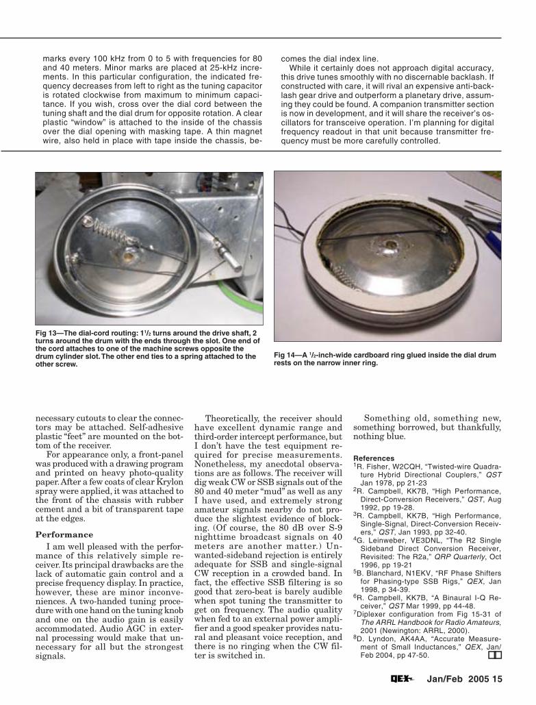
With the shaft and dial drum mounted securely, the dialcord can be installed. Fig 13 shows how the cord isrouted: 11/2 turns around the drive shaft, 2 turns aroundthe drum with the ends through the slot. Thus, the cord istangential to the drum throughout the 180° rotation of thevariable capacitor. One end of the cord is attached to oneof the machine screws opposite the slot in the drum cyl-inder, and the other end is tied to a spring attached to theother screw. Adjust the length of the cord for sufficientspring tension to prevent slipping on the drive shaft. Asthe dial is rotated, the cord will travel about ½ inch alongthe shaft length, over the prepared non-slip surface, whilethe spring keeps the tension constant.
To support the dial face, epoxy a 1/2-inch-wide ring ofcardboard inside the dial drum resting on the narrow in-ner ring as shown in Fig 14. A circular dial face may thenbe glued to the cardboard ring with rubber cement. Thisallows it to be removed or repositioned. Before the plas-tic window is mounted inside the chassis front panel, tem-porarily install the oscillator/RF/IF assembly with the dialdrum attached. Temporary markings can be made on atrial dial face at convenient frequency increments. Usingthe trial dial face as a template, make a final dial face onglossy paper by hand or with a computer graphics pro-gram and attach it to the cardboard ring with rubber ce-ment. Fig 1 shows a computer-printed dial with major
Jan/Feb 2005 15
marks every 100 kHz from 0 to 5 with frequencies for 80and 40 meters. Minor marks are placed at 25-kHz incre-ments. In this particular configuration, the indicated fre-quency decreases from left to right as the tuning capacitoris rotated clockwise from maximum to minimum capaci-tance. If you wish, cross over the dial cord between thetuning shaft and the dial drum for opposite rotation. A clearplastic “window” is attached to the inside of the chassisover the dial opening with masking tape. A thin magnetwire, also held in place with tape inside the chassis, be-
comes the dial index line.While it certainly does not approach digital accuracy,
this drive tunes smoothly with no discernable backlash. Ifconstructed with care, it will rival an expensive anti-back-lash gear drive and outperform a planetary drive, assum-ing they could be found. A companion transmitter sectionis now in development, and it will share the receiver’s os-cillators for transceive operation. I’m planning for digitalfrequency readout in that unit because transmitter fre-quency must be more carefully controlled.
necessary cutouts to clear the connec-tors may be attached. Self-adhesiveplastic “feet” are mounted on the bot-tom of the receiver.
For appearance only, a front-panelwas produced with a drawing programand printed on heavy photo-qualitypaper. After a few coats of clear Krylonspray were applied, it was attached tothe front of the chassis with rubbercement and a bit of transparent tapeat the edges.
PerformanceI am well pleased with the perfor-
mance of this relatively simple re-ceiver. Its principal drawbacks are thelack of automatic gain control and aprecise frequency display. In practice,however, these are minor inconve-niences. A two-handed tuning proce-dure with one hand on the tuning knoband one on the audio gain is easilyaccommodated. Audio AGC in exter-nal processing would make that un-necessary for all but the strongestsignals.
Fig 13—The dial-cord routing: 11/2 turns around the drive shaft, 2turns around the drum with the ends through the slot. One end ofthe cord attaches to one of the machine screws opposite thedrum cylinder slot. The other end ties to a spring attached to theother screw.
Fig 14—A 1/2-inch-wide cardboard ring glued inside the dial drumrests on the narrow inner ring.
Theoretically, the receiver shouldhave excellent dynamic range andthird-order intercept performance, butI don’t have the test equipment re-quired for precise measurements.Nonetheless, my anecdotal observa-tions are as follows. The receiver willdig weak CW or SSB signals out of the80 and 40 meter “mud” as well as anyI have used, and extremely strongamateur signals nearby do not pro-duce the slightest evidence of block-ing. (Of course, the 80 dB over S-9nighttime broadcast signals on 40meters are another matter.) Un-wanted-sideband rejection is entirelyadequate for SSB and single-signalCW reception in a crowded band. Infact, the effective SSB filtering is sogood that zero-beat is barely audiblewhen spot tuning the transmitter toget on frequency. The audio qualitywhen fed to an external power ampli-fier and a good speaker provides natu-ral and pleasant voice reception, andthere is no ringing when the CW fil-ter is switched in.
Something old, something new,something borrowed, but thankfully,nothing blue.
References1R. Fisher, W2CQH, “Twisted-wire Quadra-
ture Hybrid Directional Couplers,” QSTJan 1978, pp 21-23
2R. Campbell, KK7B, “High Performance,Direct-Conversion Receivers,” QST, Aug1992, pp 19-28.
3R. Campbell, KK7B, “High Performance,Single-Signal, Direct-Conversion Receiv-ers,” QST, Jan 1993, pp 32-40.
4G. Leinweber, VE3DNL, “The R2 SingleSideband Direct Conversion Receiver,Revisited: The R2a,” QRP Quarterly, Oct1996, pp 19-21
5B. Blanchard, N1EKV, “RF Phase Shiftersfor Phasing-type SSB Rigs,” QEX, Jan1998, p 34-39.
6R. Campbell, KK7B, “A Binaural I-Q Re-ceiver,” QST Mar 1999, pp 44-48.
7Diplexer configuration from Fig 15-31 ofThe ARRL Handbook for Radio Amateurs,2001 (Newington: ARRL, 2000).
8D. Lyndon, AK4AA, “Accurate Measure-ment of Small Inductances,” QEX, Jan/Feb 2004, pp 47-50. !!