an overview of ieee 802.15.6 standard - arxiv · pdf filean overview of ieee 802.15.6 standard...
TRANSCRIPT
An Overview of IEEE 802.15.6 Standard(Invited Paper)
Kyung Sup Kwak, Sana Ullah, and Niamat UllahUWB-ITRC Center, Inha University
253 Yonghyun-dong, Nam-gu, Incheon (402-751), South KoreaEmail: [email protected], [email protected], [email protected]
Abstract—Wireless Body Area Networks (WBAN) has emergedas a key technology to provide real-time health monitoring ofa patient and diagnose many life threatening diseases. WBANoperates in close vicinity to, on, or inside a human body andsupports a variety of medical and non-medical applications. IEEE802 has established a Task Group called IEEE 802.15.6 forthe standardization of WBAN. The purpose of the group is toestablish a communication standard optimized for low-power in-body/on-body nodes to serve a variety of medical and non-medicalapplications. This paper explains the most important featuresof the new IEEE 802.15.6 standard. The standard defines aMedium Access Control (MAC) layer supporting several Physical(PHY) layers. We briefly overview the PHY and MAC layersspecifications together with the bandwidth efficiency of IEEE802.15.6 standard. We also discuss the security paradigm of thestandard.
I. INTRODUCTION
Wireless Body Area Network (WBAN) has great potentialto revolutionize the future of healthcare technology. It hasattracted a number of researchers both from the academiaand industry in the past few years. WBAN supports a widerange of medical and Consumer Electronics (CE) applications.For example, WBAN provides remote health monitoring of apatient’s state for a long period of time without any restrictionon his/her normal activities [1]-[2]. For a successful imple-mentation of WBAN, a standard model was required whichwould be able to address both medical and CE applications.IEEE 802 established a Task Group called IEEE 802.15.61
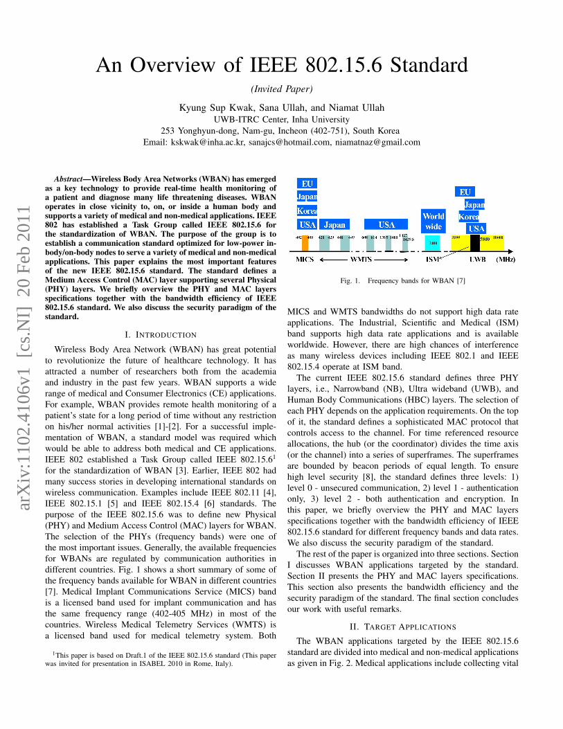
for the standardization of WBAN [3]. Earlier, IEEE 802 hadmany success stories in developing international standards onwireless communication. Examples include IEEE 802.11 [4],IEEE 802.15.1 [5] and IEEE 802.15.4 [6] standards. Thepurpose of the IEEE 802.15.6 was to define new Physical(PHY) and Medium Access Control (MAC) layers for WBAN.The selection of the PHYs (frequency bands) were one ofthe most important issues. Generally, the available frequenciesfor WBANs are regulated by communication authorities indifferent countries. Fig. 1 shows a short summary of some ofthe frequency bands available for WBAN in different countries[7]. Medical Implant Communications Service (MICS) bandis a licensed band used for implant communication and hasthe same frequency range (402-405 MHz) in most of thecountries. Wireless Medical Telemetry Services (WMTS) isa licensed band used for medical telemetry system. Both
1This paper is based on Draft.1 of the IEEE 802.15.6 standard (This paperwas invited for presentation in ISABEL 2010 in Rome, Italy).
Fig. 1. Frequency bands for WBAN [7]
MICS and WMTS bandwidths do not support high data rateapplications. The Industrial, Scientific and Medical (ISM)band supports high data rate applications and is availableworldwide. However, there are high chances of interferenceas many wireless devices including IEEE 802.1 and IEEE802.15.4 operate at ISM band.
The current IEEE 802.15.6 standard defines three PHYlayers, i.e., Narrowband (NB), Ultra wideband (UWB), andHuman Body Communications (HBC) layers. The selection ofeach PHY depends on the application requirements. On the topof it, the standard defines a sophisticated MAC protocol thatcontrols access to the channel. For time referenced resourceallocations, the hub (or the coordinator) divides the time axis(or the channel) into a series of superframes. The superframesare bounded by beacon periods of equal length. To ensurehigh level security [8], the standard defines three levels: 1)level 0 - unsecured communication, 2) level 1 - authenticationonly, 3) level 2 - both authentication and encryption. Inthis paper, we briefly overview the PHY and MAC layersspecifications together with the bandwidth efficiency of IEEE802.15.6 standard for different frequency bands and data rates.We also discuss the security paradigm of the standard.
The rest of the paper is organized into three sections. SectionI discusses WBAN applications targeted by the standard.Section II presents the PHY and MAC layers specifications.This section also presents the bandwidth efficiency and thesecurity paradigm of the standard. The final section concludesour work with useful remarks.
II. TARGET APPLICATIONS
The WBAN applications targeted by the IEEE 802.15.6standard are divided into medical and non-medical applicationsas given in Fig. 2. Medical applications include collecting vital
arX
iv:1
102.
4106
v1 [
cs.N
I] 2
0 Fe
b 20
11
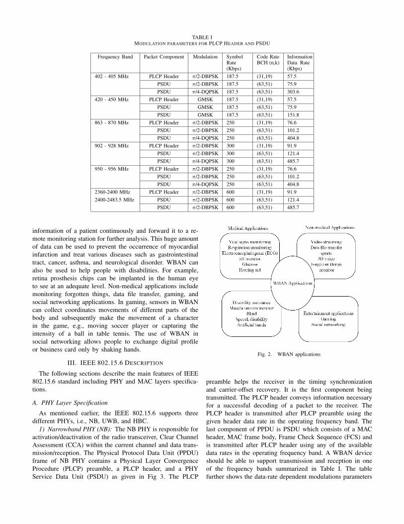
TABLE IMODULATION PARAMETERS FOR PLCP HEADER AND PSDU
Frequency Band Packet Component Modulation SymbolRate(Kbps)
Code RateBCH (n,k)
InformationData Rate(Kbps)
402 - 405 MHz PLCP Header π/2-DBPSK 187.5 (31,19) 57.5PSDU π/2-DBPSK 187.5 (63,51) 75.9PSDU π/4-DQPSK 187.5 (63,51) 303.6
420 - 450 MHz PLCP Header GMSK 187.5 (31,19) 57.5PSDU GMSK 187.5 (63,51) 75.9PSDU GMSK 187.5 (63,51) 151.8
863 - 870 MHz PLCP Header π/2-DBPSK 250 (31,19) 76.6PSDU π/2-DBPSK 250 (63,51) 101.2PSDU π/4-DQPSK 250 (63,51) 404.8
902 - 928 MHz PLCP Header π/2-DBPSK 300 (31,19) 91.9PSDU π/2-DBPSK 300 (63,51) 121.4PSDU π/4-DQPSK 300 (63,51) 485.7
950 - 956 MHz PLCP Header π/2-DBPSK 250 (31,19) 76.6PSDU π/2-DBPSK 250 (63,51) 101.2PSDU π/4-DQPSK 250 (63,51) 404.8
2360-2400 MHz PLCP Header π/2-DBPSK 600 (31,19) 91.92400-2483.5 MHz PSDU π/2-DBPSK 600 (63,51) 121.4
PSDU π/2-DBPSK 600 (63,51) 485.7
information of a patient continuously and forward it to a re-mote monitoring station for further analysis. This huge amountof data can be used to prevent the occurrence of myocardialinfarction and treat various diseases such as gastrointestinaltract, cancer, asthma, and neurological disorder. WBAN canalso be used to help people with disabilities. For example,retina prosthesis chips can be implanted in the human eyeto see at an adequate level. Non-medical applications includemonitoring forgotten things, data file transfer, gaming, andsocial networking applications. In gaming, sensors in WBANcan collect coordinates movements of different parts of thebody and subsequently make the movement of a characterin the game, e.g., moving soccer player or capturing theintensity of a ball in table tennis. The use of WBAN insocial networking allows people to exchange digital profileor business card only by shaking hands.
III. IEEE 802.15.6 DESCRIPTION
The following sections describe the main features of IEEE802.15.6 standard including PHY and MAC layers specifica-tions.
A. PHY Layer Specification
As mentioned earlier, the IEEE 802.15.6 supports threedifferent PHYs, i.e., NB, UWB, and HBC.
1) Narrowband PHY (NB): The NB PHY is responsible foractivation/deactivation of the radio transceiver, Clear ChannelAssessment (CCA) within the current channel and data trans-mission/reception. The Physical Protocol Data Unit (PPDU)frame of NB PHY contains a Physical Layer ConvergenceProcedure (PLCP) preamble, a PLCP header, and a PHYService Data Unit (PSDU) as given in Fig 3. The PLCP
Fig. 2. WBAN applications
preamble helps the receiver in the timing synchronizationand carrier-offset recovery. It is the first component beingtransmitted. The PLCP header conveys information necessaryfor a successful decoding of a packet to the receiver. ThePLCP header is transmitted after PLCP preamble using thegiven header data rate in the operating frequency band. Thelast component of PPDU is PSDU which consists of a MACheader, MAC frame body, Frame Check Sequence (FCS) andis transmitted after PLCP header using any of the availabledata rates in the operating frequency band. A WBAN deviceshould be able to support transmission and reception in oneof the frequency bands summarized in Table I. The tablefurther shows the data-rate dependent modulations parameters

Fig. 3. IEEE 802.15.6 NB PPDU structure
Fig. 4. IEEE 802.15.6 UWB PPDU structure
Fig. 5. IEEE 802.15.6 EFC PPDU structure
for PLCP header and PSDU. In NB PHY, the standard usesDifferential Binary Phase-shift Keying (DBPSK), DifferentialQuadrature Phase-shift Keying (DQPSK), and Differential 8-Phase-shift Keying (D8PSK) modulation techniques except420-450 MHz which uses a Gaussian minimum shift keying(GMSK) technique.
2) Ultra Wideband PHY (UWB): UWB PHY operates intwo frequency bands: low band and high band. Each band isdivided into channels, all of them characterized by a bandwidthof 499.2 MHz. The low band consists of 3 channels (1-3) only.The channel 2 has a central frequency of 3993.6 MHz and isconsidered a mandatory channel. The high band consists ofeight channels (4-11) where channel 7 with a central frequency7987.2 MHz is considered a mandatory channel, while allother channels are optional. A typical UWB device shouldsupport at least one of the mandatory channels. The UWBPHY transceivers allow low implementation complexity andgenerate signal power levels in the order of those used in theMICS band.
Fig. 4 shows the UWB PPDU that contains a Synchroniza-tion Header (SHR), a PHY Header (PHR), and PSDU. The
SHR is composed of a preamble and a Start Frame Delimiter(SFD). The PHR conveys information about the data rate ofthe PSDU, length of the payload and scrambler seed. Theinformation in the PHR is used by the receiver in order todecode the PSDU. The SHR is formed of repetitions of Kasamisequences of length 63. Typical data rates range from 0.5 Mbpsup to 10 Mbps with 0.4882 Mbps as the mandatory one.
3) Human Body Communications PHY (HBC): HBC PHYoperates in two frequency bands centered at 16 MHz and 27MHz with the bandwidth of 4 MHz. Both operating bands arevalid for the United States, Japan, and Korea, and the operatingband at 27MHz is valid for Europe. HBC is the ElectrostaticField Communication (EFC) specification of PHY, whichcovers the entire protocol for WBAN such as packet structure,modulation, preamble/SFD, etc. Fig. 5 describes the PPDUstructure of EFC that is composed of a preamble, SFD, PHYheader and PSDU. The preamble and SFD are fixed datapatterns. They are pre-generated and sent ahead of the packetheader and payload. The preamble sequence is transmittedfour times in order to ensure packet synchronization while theSFD is transmitted only once. When the packet is received by

Fig. 6. IEEE 802.15.6 superframe structure
Fig. 7. CSMA/CA procedure in IEEE 802.15.6 standard
the receiver, it finds the start of the packet by detecting thepreamble sequence, and then it finds the start of the frame bydetecting the SFD.
B. MAC Layer Specification
In IEEE 802.15.6, the entire channel is divided into super-frame structures. Each superframe is bounded by a beaconperiod of equal length. The hub selects the boundaries of thebeacon period and thereby selects the allocation slots. Thehub may also shift the offsets of the beacon period. Generally,the beacons are transmitted in each beacon period except ininactive superframes or unless prohibited by regulations suchas in MICS band. The IEEE 802.15.6 network operates in oneof the following modes.
1) Beacon mode with beacon period superframe bound-aries: In this mode, the beacons are transmitted by thehub in each beacon period except in inactive superframes orunless prohibited by regulations. Fig. 6 shows the superframestrucutre of IEEE 802.15.6, which is divided into ExclusiveAccess Phase 1 (EAP1), Random Access Phase 1 (RAP1),Type I/II phase, Exclusive Access Phase 2 (EAP 2), RandomAccess Phase 2 (RAP 2), Type I/II phase, and a ContentionAccess Phase (CAP). In EAP, RAP and CAP periods, nodescontend for the resource allocation using either CSMA/CA or aslotted Aloha access procedure. The EAP1 and EAP2 are usedfor highest priority traffic such as reporting emergency events.The RAP1, RAP2, and CAP are used for regular traffic only.The Type I/II phases are used for uplink allocation intervals,downlink allocation intervals, bilink allocation intervals, anddelay bilink allocation intervals. In Type I/II phases, pollingis used for resource allocation. Depending on the application
requirements, the coordinator can disable any of these periodsby setting the duration length to zero.
2) Non-beacon mode with superframe boundaries: In thismode, the entire superframe duration is covered either by atype I or a type II access phase but not by both phases.
3) Non-beacon mode without superframe boundaries: Inthis mode, the coordinator provides unscheduled Type II polledallocation only.
The access mechanisms used in each period of the su-perframe are divided into three categories: 1) Random ac-cess mechanism, which uses either CSMA/CA or a slottedAloha procedure for resource allocation, 2) Improvised andunscheduled access (connectionless contention-free access),which uses unscheduled polling/posting for resource allo-cation, and 3) Scheduled access and variants (connection-oriented contention-free access), which schedules the allo-cation of slots in one or multiple upcoming superframes,also called 1-periodic or m-periodic allocations. These mech-anisms are comprehensively discussed in the standard. Herewe explain the basic procedures of the CSMA/CA protocoldefined in the standard. In CSMA/CA, a node sets its backoffcounter to a random integer number uniformly distributedover the interval [1, CW ] where CW ∈ (CWmin, CWmax).The values of of CWmin and CWmax vary depending onthe user priorities. The node starts decrementing the backoffcounter by one for each idle CSMA slot of duration equalto pCSMASlotLength. The data is transmitted when thebackoff counter reaches zero. If the channel is busy because ofa frame transmission, the node locks its backoff counter untilthe channel is idle. The CW is doubled for even number offailures (when the node fails to receive an acknowledgement
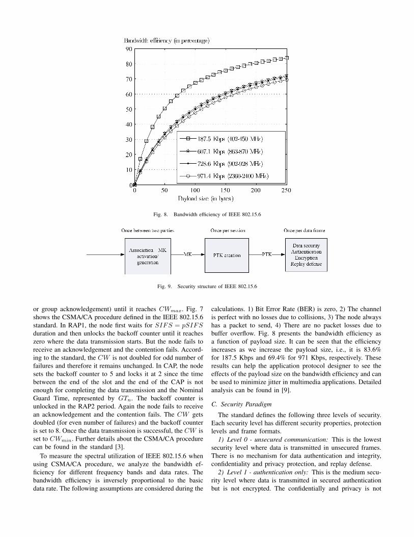
Fig. 8. Bandwidth efficiency of IEEE 802.15.6
Fig. 9. Security structure of IEEE 802.15.6
or group acknowledgement) until it reaches CWmax. Fig. 7shows the CSMA/CA procedure defined in the IEEE 802.15.6standard. In RAP1, the node first waits for SIFS = pSIFSduration and then unlocks the backoff counter until it reacheszero where the data transmission starts. But the node fails toreceive an acknowledgement and the contention fails. Accord-ing to the standard, the CW is not doubled for odd number offailures and therefore it remains unchanged. In CAP, the nodesets the backoff counter to 5 and locks it at 2 since the timebetween the end of the slot and the end of the CAP is notenough for completing the data transmission and the NominalGuard Time, represented by GTn. The backoff counter isunlocked in the RAP2 period. Again the node fails to receivean acknowledgement and the contention fails. The CW getsdoubled (for even number of failures) and the backoff counteris set to 8. Once the data transmission is successful, the CW isset to CWmin. Further details about the CSMA/CA procedurecan be found in the standard [3].
To measure the spectral utilization of IEEE 802.15.6 whenusing CSMA/CA procedure, we analyze the bandwidth ef-ficiency for different frequency bands and data rates. Thebandwidth efficiency is inversely proportional to the basicdata rate. The following assumptions are considered during the
calculations. 1) Bit Error Rate (BER) is zero, 2) The channelis perfect with no losses due to collisions, 3) The node alwayshas a packet to send, 4) There are no packet losses due tobuffer overflow. Fig. 8 presents the bandwidth efficiency asa function of payload size. It can be seen that the efficiencyincreases as we increase the payload size, i.e., it is 83.6%for 187.5 Kbps and 69.4% for 971 Kbps, respectively. Theseresults can help the application protocol designer to see theeffects of the payload size on the bandwidth efficiency and canbe used to minimize jitter in multimedia applications. Detailedanalysis can be found in [9].
C. Security Paradigm
The standard defines the following three levels of security.Each security level has different security properties, protectionlevels and frame formats.
1) Level 0 - unsecured communication: This is the lowestsecurity level where data is transmitted in unsecured frames.There is no mechanism for data authentication and integrity,confidentiality and privacy protection, and replay defense.
2) Level 1 - authentication only: This is the medium secu-rity level where data is transmitted in secured authenticationbut is not encrypted. The confidentially and privacy is not
supported by this mode.3) Level 3 - authentication and encryption: This is the
highest security level where data is transmitted in securedauthentication and encryption frames. It provides solutions toall of the problems not covered by the level 0 and level 1.
The required security level is selected during the associationprocess, i.e., when a node is joining the network. For unicastcommunication, a pre-shared Master Key (MK) or a newkey (established via unauthenticated association) is activated.Then a Pairwise Temporal Key (PTK) is established, whichis used once per session. For multicast communication, aGroup Temporal Key (GTK) is shared with the correspondingmulticast group. The whole security structure is given in Fig.9.
IV. CONCLUSION
This paper presented a brief overview of the new IEEE802.15.6 standard. We studied the PHY and MAC layersspecifications and identified their key points. In addition,we analyzed the bandwidth efficiency of the standard forCSMA/CA procedure. The efficiency results were presentedfor different frequency bands and data rates. We observed thatincrease in the payload size improves the bandwidth efficiency.We also highlighted different security modes of the standard.This paper can be used to quickly understand the key conceptsof IEEE 802.15.6 without reading the whole standard.
ACKNOWLEDGMENT
This work was supported by the National Research Foun-dation of Korea (NRF) grant funded by the Korea government(MEST)(No. No.2010-0018116).
REFERENCES
[1] S. Ullah, H. Higgins, B. Braem, B. Latre, C. Blondia, I. Moerman, S.Saleem, Z. Rahman and K.S. Kwak,A Comprehensive Survey of WirelessBody Area Networks: On PHY, MAC, and Network Layers Solutions,Journal of Medical Systems, IN PRESS, DOI: 10.1007/s10916-010-9571-3.
[2] M. Chen, S. Gonzalez, A. Vasilakos, H. Cao, and V.C.M. Leung,Body Area Networks: A Survey, ACM/Springer Mobile Networks andApplications (MONET), 2010 (IN PRESS), DOI: 10.1007/s11036-010-0260-8.
[3] IEEE P802.15.6/D01,Wireless Medium Access Control (MAC) and Phys-ical Layer (PHY) Specifications for Wireless Personal Area Networks(WPANs) used in or around a body, May 2010.
[4] IEEE WLAN, http://www.ieee802.org/11/[5] IEEE WPAN Task Group 1, http://www.ieee802.org/15/pub/TG1.html[6] IEEE WPAN Task Group 4, http://www.ieee802.org/15/pub/TG4.html[7] A. W. ASTRIN, H.-B. LI, and R. KOHNO, standardization forbody area
networks, IEICE Transactions on Communications, vol. E92.B, no. 2, pp.366.372, 2009.
[8] S. Saleem, S. Ullah, and K.S. Kwak, A Study of IEEE 802.15.4 SecurityFramework for Wireless Body Area Networks, Sensors, vol.11, No.2, pp.1383-1395, 2011.
[9] S. Ullah and K.S. Kwak, Throughput and Delay Limits of IEEE 802.15.6,IEEE WCNC 2011, 2011.