anaesthesia regularization during surgeries by using heart...
TRANSCRIPT
164 Sushma Chowdary Polavarapu, Kranthi Madala , Sri Hari Nallamala
International Journal of Engineering Technology Science and Research
IJETSR
www.ijetsr.com
ISSN 2394 – 3386
Volume 4, Issue 3
March 2017
Anaesthesia Regularization during Surgeries by using
Heart Beat Sensor
Sushma Chowdary
Polavarapu
Assistant Professor, EIE Dept.,
V.R. Siddhartha Engineering
College, Vijayawada, Krishna
Dist., A.P.
Kranthi Madala
Assistant Professor, EIE Dept.,
V.R. Siddhartha Engineering
College, Vijayawada, Krishna
Dist., A.P.
Sri Hari Nallamala
Assistant Professor, CSE
Dept., DVR & Dr.HS MIC
College of Technology,
Krishna Dist., A.P.
ABSTRACT In hospitals when any major surgery is performed, the patient must be in anesthetize condition. If the surgery
lasts for a long time, say for more than four hours, complete dose of Anaesthesia cannot be administered in a single dose.
If given, it may lead to the patient’s death. If lower amount of Anaesthesia is administered, the patient may wakeup at the
middle of the surgery. To avoid such problems, an automated Anaesthesia machine based on microcontroller is designed.
In this system, a keypad is provided along with the microcontroller and syringe infusion pump. The anesthetist can set
the level of Anaesthesia in terms of milliliters per hour to administer Anaesthesia to the patient with the help of keypad.
The heart beat sensor senses the change in heart beat rate. If there is any change in the heart beat rate, the
microcontroller controls the signal to the desired level and fed into the stepper motor to drive the infusion pump in
proper manner. Now, the Anaesthesia is administered to the patient according to the motor rotation. On the basis of
heart beat rate of the patient, the anesthetic drug will be injected as per the normal and abnormal ranges. This paper is
based on automation and will be very much useful to physician to see the current position of Anaesthesia of patient so
that proper amount of Anaesthesia will be injected to the patient. Protection is intelligent than prevention and our paper
on automatic Anaesthesia injector is one of the efficient protecting system.
Key words: Anaesthesia, Hear Beat Sensor, Automated Microcontroller, Automatic Anaesthesia Injector
1. INTRODUCTION:
Major surgeries are performed to remove or reconstruct the infected parts in the human body. These
surgeries will lead to blood loss and pain. Therefore it is necessary to arrest the pain and the blood loss.
Anaesthesia plays an important role in the part of painkilling. So when a surgery is performed the patient must
be in anesthetizing condition. If the surgery lasts for a long time, say for suppose for 4 or 5 hours, complete
dose of Anaesthesia cannot be administered in a single stroke. It may lead to the patient‟s death. If lower
amount of Anaesthesia is administered, the patient may wakeup at the middle of the surgery. To overcome
such hazardous problems the design of an automatic surgery of an Anaesthesia machine based on a micro-
controller is effective. Automatic Anaesthesia Injection can be defined as “Automatic administration of
Anaesthesia based on the bio-medical parameters of the patient, eliminating future side effects and the need
for an anesthetist”. Anaesthesia is very essential in performing painless surgery and so an Automatic
administration of Anaesthesia is needed for a successful surgery.
2. What is ANAESTHESIA?
The word „Anaesthesia‟ means „loss of sensation‟. Anaesthesia [5] is a way to control pain during a
surgery or procedure by using medicine called Anesthetics. It can help control your breathing, blood pressure,
blood flow, and heart rate. Not all type of Anaesthesia can make you unconscious. It can be applied to various
parts of the body.
Anaesthesia may be used to:
Relax you.
Block pain.
Make you sleepy or forgetful.
Other medicines may be used along with Anaesthesia, such as ones to help you relax or to reverse the
effects of Anaesthesia.
165 Sushma Chowdary Polavarapu, Kranthi Madala , Sri Hari Nallamala
International Journal of Engineering Technology Science and Research
IJETSR
www.ijetsr.com
ISSN 2394 – 3386
Volume 4, Issue 3
March 2017
2.1 Types of Anaesthesia:
There are three main types of Anaesthesia. They are:
General Anaesthesia: General Anaesthesia [5] puts you to sleep, which means that you remain in a state
of unconsciousness. For some surgeries general Anaesthesia is essential. Before your surgery starts
anesthetic drugs are injected into the vein or sometimes, instead, anesthetic gases are delivered to the
lungs. The drugs or gases will be carried to the brain in the bloodstream, leading to the unconsciousness
state. As the drugs/gases wear off, your consciousness and sensations will gradually return.
Regional Anaesthesia: Regional Anaesthesia [5] blocks pain to a larger part of your body. You may also
get medicine to help you relax or sleep.
Types of regional Anaesthesia include:
Peripheral nerve blocks: This is a shot of anesthetic to block pain around a specific nerve or group of
nerves. Blocks are often used for procedures on the hands, arms, feet, legs, or face.
Epidural and spinal Anaesthesia: This is a shot of anesthetic near the spinal cord and the nerves that
connect to it. It blocks pain from an entire region of the body, such as the belly, hips, or legs.
Local Anaesthesia: Local Anaesthesia [5] numbs a small part of the body.
The regional or local Anaesthesia do not lead to the loss of consciousness, they only cause the elimination
of pain. However, it is possible to complement those methods with sedation, using small amounts of
anesthetic or similar drugs to make the patient feel sleepy and relaxed during a procedure.
Sedation can also be used as the only method during procedures that do not require Anaesthesia, but may
be unpleasant or uncomfortable [5].
3. Existing Procedure:
Anaesthetist is a medical doctor who administers Anaesthesia and monitors and manages patients
before, during and immediately following a medical or surgical procedure. Anaesthetists can also practice
pain management, critical or intensive care medicine and can administer and monitor epidural Anaesthesia in
child labour and delivery, among other specialties.
At present anesthetist controlled manual surgery is employed, which may cause many difficulties
such as,
Level of Anaesthesia may get varied and there is a chance of getting side effects in future.
If suppose the anesthetist fails to administer the level of Anaesthesia during the predetermined period, the
patient may be disturbed during the surgery.
Other systems developed to administer Anaesthesia operate by sensing the consciousness level of the
patient and not by measuring his overall body conditions.
4. Our New Proposed System:
In this design, a micro-controller is used for controlling the Anaesthesia machine automatically,
depending upon the various biomedical parameters such as body temperature, heart rate, respiration rate etc.
Advantages of using the proposed system are,
The need for an anesthetist is eliminated.
Level of Anaesthesia is not varied, so the future side effects are eliminated.
IR detector is also included in the system for monitoring the total Anaesthesia level for the entire period of the
surgery time.
166 Sushma Chowdary Polavarapu, Kranthi Madala , Sri Hari Nallamala
International Journal of Engineering Technology Science and Research
IJETSR
www.ijetsr.com
ISSN 2394 – 3386
Volume 4, Issue 3
March 2017
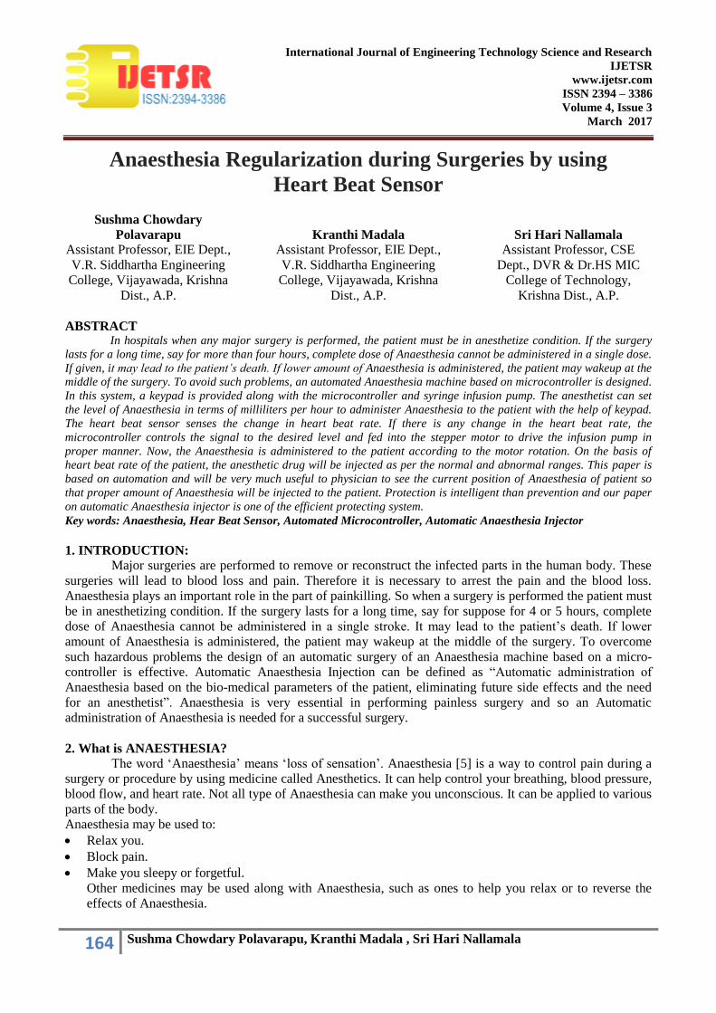
Figure 1: Block Diagram of Automatic Anaesthesia Injector
5. Components Required:
Temperature Sensor – to measure the body temperature.
Respiration Sensor – to measure rate of respiration per minute.
Heart Beat Sensor – to measure the heartbeat rate per minute.
Micro Controller – to control the overall surgery.
Stepper Motor – to control the movement of the Syringe Infusion Pump.
A/D Converter – to convert the analog information into a digital format.
6. Working of the System:
The block diagram of Automatic Anesthesia Injector was shown above in Figure 1. By using the
keypad provided along with the Microcontroller, the anesthetist can set the level of Anaesthesia to be
administered to the patient in terms of milliliters per hour (1ml to 1000ml). After receiving the Anaesthesia
level from the keypad, the Microcontroller sets the system to administer Anaesthesia to the prescribed level. It
then analyses various bio-medical parameters obtained from the sensors to determine the direction of rotation
of the stepper motor.
The rotation of the stepper motor causes the Infusion Pump to move in forward or in a backward
direction and the Anaesthesia provided in the syringe is injected into the body of the patient. If the level of
Anaesthesia is decreased to lower level than the set value, the alarm gets activated to alert the anesthetist to
refill the Anaesthesia in the syringe pump to continue the process. In this design, the total timing and opposite
flow of blood will also be detected by using the Micro Controller.
7. Measurement of Bio-Medical Parameters:
The measurement of bio-medical parameters is a vital process. These parameters determine the
overall condition of the patient. It plays a very significant process in the level of Anaesthesia that has to be
administered to the patient. Only based on these parameters the movement of the stepper motor is determined.
Transducers and Thermistors are the key links in all sensors designed to describe and analyze the bio-medical
parameters. The transducers used here are just those that find applications in patient monitoring systems and
experimental work on three parameters namely temperature, heart beat and respiratory activity. Both
transducers and thermistors are made in a wide variety of forms suitable for use in medical applications. They
are available as wafers for applying on the skin surfaces tiny beads for inserting into the tissues.
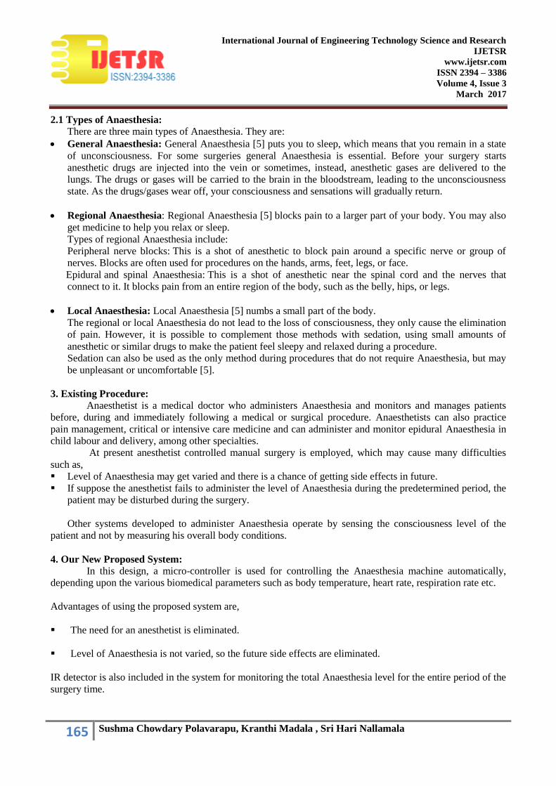
7.1. Temperature Sensor:
The most accurate method to measure temperature is to use Thermistors and Resistance
Thermometers. Of all the major categories of temperature sensors, the thermistor exhibits by far the largest
parameter range with temperature. Thermistor or thermal resistor is a two-terminal semiconductor device
whose resistance is temperature sensitive. Although positive temperature coefficient units are available, most
thermistors have a negative temperature coefficient. The value of their resistance decreases with increase in
temperature. The thermistors have very high temperature coefficient of resistance of the order of 3% to 5%
167 Sushma Chowdary Polavarapu, Kranthi Madala , Sri Hari Nallamala
International Journal of Engineering Technology Science and Research
IJETSR
www.ijetsr.com
ISSN 2394 – 3386
Volume 4, Issue 3
March 2017
per ºC, making it an ideal temperature transducer. The thermistor is an extremely non-linear device which is
highly dependent upon the process parameters. The output of the temperature sensor is given to the amplifier
stages. Resistance thermometers can also be used to measure the body temperature. Important characteristics
of resistance thermometers are high temperature co-efficient to resistance, stable properties so that the
resistance characteristics does not drift with repeated heating or cooling or mechanical strain and high
resistivity to permit the construction of small sensors.
Figure 2: Circuit to measure Temperature
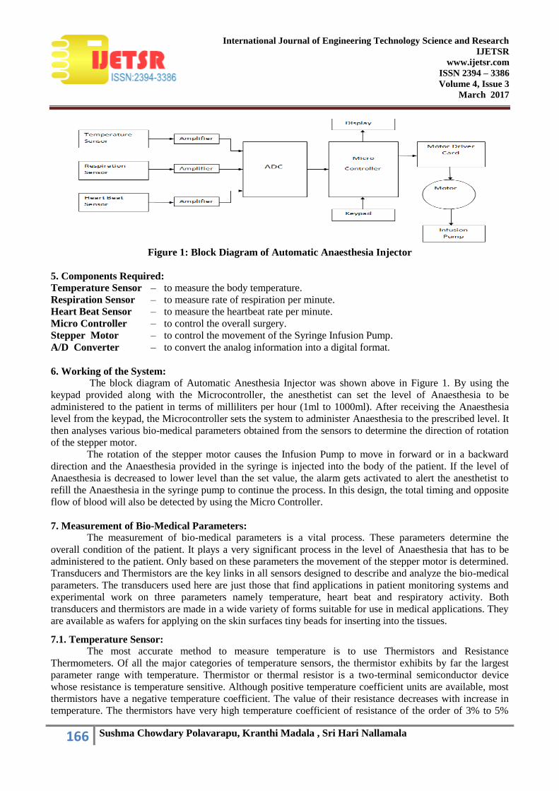
7.2 Respiration Sensor:
The primary functions of the respiratory system are to supply oxygen to the tissues and remove
carbon dioxide from the tissues. The action of breathing is controlled by muscular action causing the volume
of the lung to increase and decrease to affect a precise and sensitive control of the tension of carbon dioxide in
the arterial blood. Under normal circumstances, this is rhythmic action. Respiratory activity can be detected
by measuring changes in the impedance across the thorax. Several types of transducers have been developed
for the measurement of respiration rate. A Strain Gauge type Chest Transducer is a suitable transducer to
measure the respiratory activity. The respiratory cycle is accompanied by variations in the thoracic volume.
Such variations can be detected by means of a displacement transducer incorporating a strain gauge or a
variable resistance element. The transducer is held by an elastic band around the chest. The respiratory
movements result in resistance variations of the strain gauge element connected in one arm of a Wheatstone
bridge circuit. Bridge circuit output varies with chest expansion and yields signals corresponding to
respiratory activity.
Variations in chest circumference can also be detected by a rubber tube filled with mercury. The tube
is fastened firmly around the chest. With the expansion of the chest during the inspiratory phase, the rubber
tube increases in length and so the resistance of the mercury from one end of this tube to the other varies.
Resistance variations may be measured by passing a constant current through it and measuring the variations
in voltage developed with the respiratory cycle.
Figure 3: Circuit to measure Respiration
168 Sushma Chowdary Polavarapu, Kranthi Madala , Sri Hari Nallamala
International Journal of Engineering Technology Science and Research
IJETSR
www.ijetsr.com
ISSN 2394 – 3386
Volume 4, Issue 3
March 2017
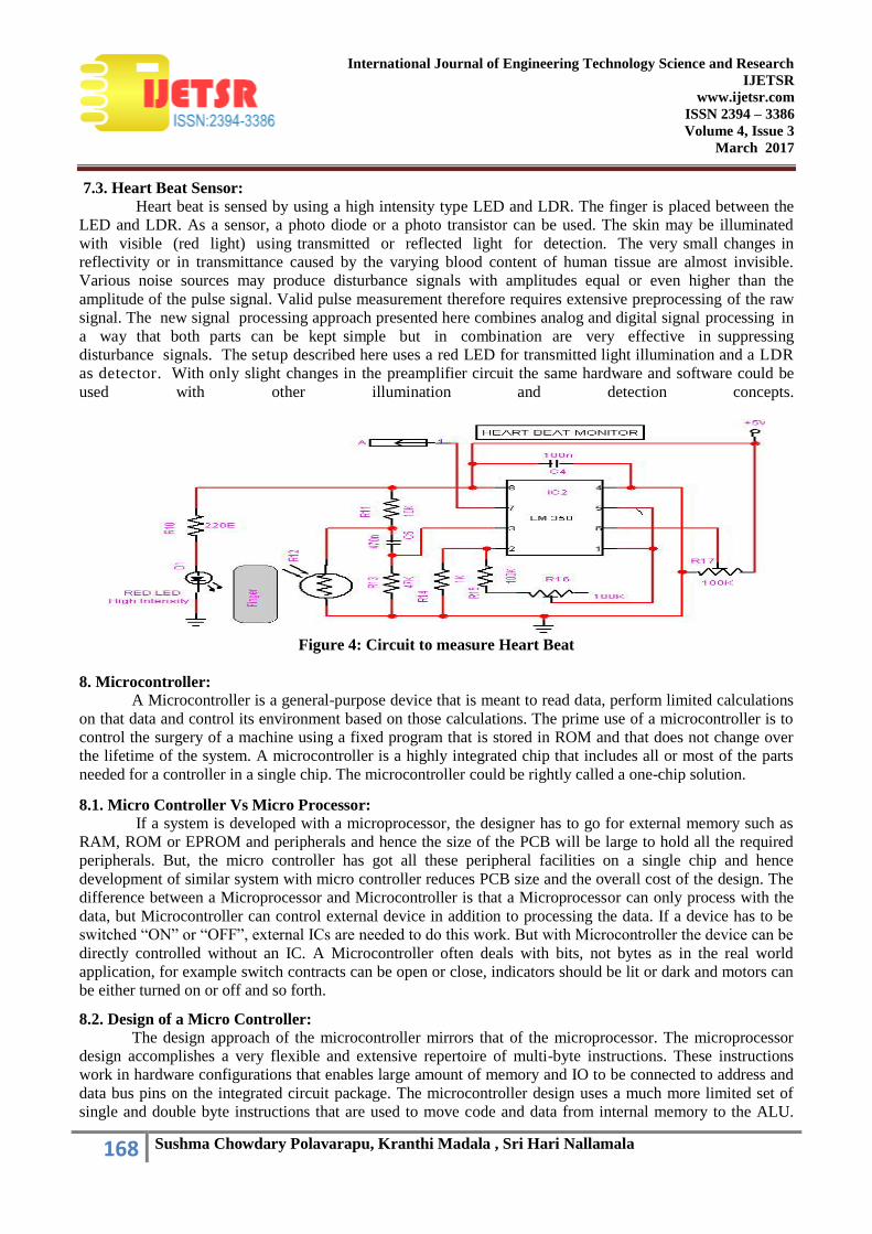
7.3. Heart Beat Sensor: Heart beat is sensed by using a high intensity type LED and LDR. The finger is placed between the
LED and LDR. As a sensor, a photo diode or a photo transistor can be used. The skin may be illuminated
with visible (red light) using transmitted or reflected light for detection. The very small changes in
reflectivity or in transmittance caused by the varying blood content of human tissue are almost invisible.
Various noise sources may produce disturbance signals with amplitudes equal or even higher than the
amplitude of the pulse signal. Valid pulse measurement therefore requires extensive preprocessing of the raw
signal. The new signal processing approach presented here combines analog and digital signal processing in
a way that both parts can be kept simple but in combination are very effective in suppressing
disturbance signals. The setup described here uses a red LED for transmitted light illumination and a LDR
as detector. With only slight changes in the preamplifier circuit the same hardware and software could be
used with other illumination and detection concepts.
Figure 4: Circuit to measure Heart Beat
8. Microcontroller:
A Microcontroller is a general-purpose device that is meant to read data, perform limited calculations
on that data and control its environment based on those calculations. The prime use of a microcontroller is to
control the surgery of a machine using a fixed program that is stored in ROM and that does not change over
the lifetime of the system. A microcontroller is a highly integrated chip that includes all or most of the parts
needed for a controller in a single chip. The microcontroller could be rightly called a one-chip solution.
8.1. Micro Controller Vs Micro Processor:
If a system is developed with a microprocessor, the designer has to go for external memory such as
RAM, ROM or EPROM and peripherals and hence the size of the PCB will be large to hold all the required
peripherals. But, the micro controller has got all these peripheral facilities on a single chip and hence
development of similar system with micro controller reduces PCB size and the overall cost of the design. The
difference between a Microprocessor and Microcontroller is that a Microprocessor can only process with the
data, but Microcontroller can control external device in addition to processing the data. If a device has to be
switched “ON” or “OFF”, external ICs are needed to do this work. But with Microcontroller the device can be
directly controlled without an IC. A Microcontroller often deals with bits, not bytes as in the real world
application, for example switch contracts can be open or close, indicators should be lit or dark and motors can
be either turned on or off and so forth.
8.2. Design of a Micro Controller:
The design approach of the microcontroller mirrors that of the microprocessor. The microprocessor
design accomplishes a very flexible and extensive repertoire of multi-byte instructions. These instructions
work in hardware configurations that enables large amount of memory and IO to be connected to address and
data bus pins on the integrated circuit package. The microcontroller design uses a much more limited set of
single and double byte instructions that are used to move code and data from internal memory to the ALU.
169 Sushma Chowdary Polavarapu, Kranthi Madala , Sri Hari Nallamala
International Journal of Engineering Technology Science and Research
IJETSR
www.ijetsr.com
ISSN 2394 – 3386
Volume 4, Issue 3
March 2017
The pins are programmable that is capable of having several different functions depending on the wishes of
the programmer. It is concerned with getting data from and to its own pins.
8.3. 89c51 Micro Controller:
The Microcontroller that is used in this system is 89C51 manufactured by Atmel, MC, USA.
This is an advanced version of 8031.
SERIES: 89C51 Family
TECHNOLOGY: CMOS
The major features of 8-bit micro controller ATMEL 89C51:
8 Bit CPU optimized for control applications
Extensive Boolean processing (Single-bit Logic) Capabilities
On-chip Flash Program Memory
On-chip Data RAM
Bi-directional and Individually Addressable I/O Lines
Multiple 16-Bit Timer/Counters
Full Duplex UART
Multiple Source/Vector/Priority Interrupt Structure
On-Chip Oscillator and Clock circuitry
On-Chip EPROM
SPI Serial Bus Interface
Watch Dog Timer
8.3.1. Flash Rom:
The 4-kb ROM in the microprocessor can be erased and reprogrammed. If the available memory is
not enough for the program an external ROM can be interfaced with this IC. AT89C51 has 16 address lines,
so a maximum of (2^16) i.e. 64 bytes of ROM can be interfaced. Both internal and external ROM can be used
simultaneously.
8.3.2. Ram:
The Microcontroller provides internal 256 bytes of RAM. Theses 256 bytes of internal RAM can be
used along with the external RAM. Externally a 64-kb of RAM can be connected with the microcontroller. In
internal RAM first 128 bytes of RAM is available for the user and the remaining128 bytes are used as special
function registers (SFR). These SFRs are used as control registers for timer, serial port etc.
Input / Output port Four I/O ports are available in AT89C51. They are Port 0, Port 1, Port2 and Port 3. These
ports are eight bit ports and can be controlled individually. In addition to this the ports also has pull-up
registers to maximize its use.
8.3.3. Interrupts:
The AT 89C51 provides 5 Interrupt sources:
2 external interrupts – INT0 and INT1
2 timer interrupts – TF0 and TF1
A serial port interrupts.
8.3.4. Memory:
The memory is logically separated into Program memory and Data memory. This logical separation
allows the data memory to be addressed by 8-bit address. Program memory can only read the information.
There can be up to 64 bytes of directly addressable program memory.
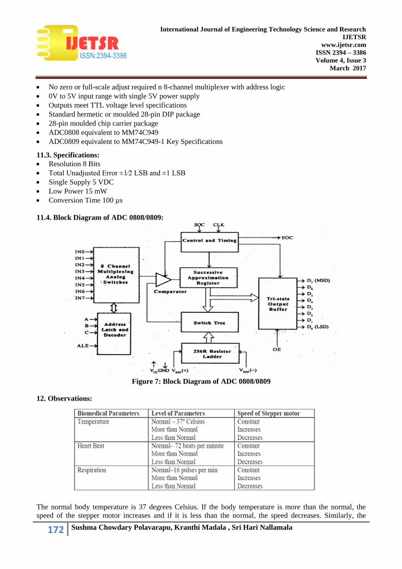
ADC 0808/0809 The ADC 0808/0809 is an 8-bit digital to analog converter with 8-channel inbuilt
Multiplexer. It is the monolithic CMOS device manufactured by the National semiconductors. It uses the
principle of Successive Approximation technique for the conversion process. The 8-channel Multiplexer can
directly access any of the 8-single-ended analog signals. Easy interfacing to the microcontrollers is provided
by the latched and decoded multiplexers address inputs and latched TTL TIR-STATE outputs.

170 Sushma Chowdary Polavarapu, Kranthi Madala , Sri Hari Nallamala
International Journal of Engineering Technology Science and Research
IJETSR
www.ijetsr.com
ISSN 2394 – 3386
Volume 4, Issue 3
March 2017
The salient features are:
High Speed and Accuracy
Minimal temperature Dependence
Excellent temperature dependence
Excellent long term accuracy & repeatability
Consumes minimal power. (15 mW)
8.4. Block Diagram of 89c51:
Figure 5: Block diagram of 895C1 Micro Controller
9. Stepper Motor:
A stepper motor transforms electrical pulses into equal increments of rotary shaft motion called steps.
A one-to-one correspondence exists between the electrical pulses and the motor steps. They work in
conjunction with electronic switching devices. The function of switching device is to switch the control
windings of the stepper motor with a frequency and sequence corresponding to the issued command. It has a
wound stator and a non exited rotor. Stepper motors are classified as 2-phase, 3-phase or 4-phase depending
on the number of windings on the stator.
9.1. Stepper Motor Driver Circuit:
In Automatic Anaesthesia Injector, a 4-phase stepper motor is used. Consider the four phases as S1,
S2, S3 and S4. The switch sequence can be used to rotate the motor half steps of 0.9º clockwise or counter
clockwise.
To take first step clockwise from S2 and S1 being on, the pattern of 1‟s and 0‟s is simply rotated one
bit position around to the right. The 1 from S1 is rotated around into bit 4. To take the next step the switch
pattern is rotated one more bit position. To step anti-clockwise the pattern is rotated to the left by one bit
position.
171 Sushma Chowdary Polavarapu, Kranthi Madala , Sri Hari Nallamala
International Journal of Engineering Technology Science and Research
IJETSR
www.ijetsr.com
ISSN 2394 – 3386
Volume 4, Issue 3
March 2017
This clockwise and counter clockwise movement of the stepper motor is coordinated with the movement of
the Syringe by means of a mechanical interface.
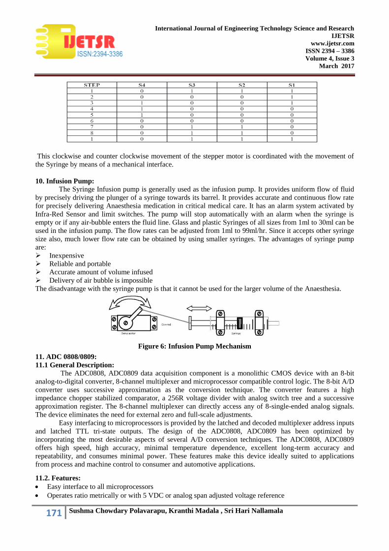
10. Infusion Pump: The Syringe Infusion pump is generally used as the infusion pump. It provides uniform flow of fluid
by precisely driving the plunger of a syringe towards its barrel. It provides accurate and continuous flow rate
for precisely delivering Anaesthesia medication in critical medical care. It has an alarm system activated by
Infra-Red Sensor and limit switches. The pump will stop automatically with an alarm when the syringe is
empty or if any air-bubble enters the fluid line. Glass and plastic Syringes of all sizes from 1ml to 30ml can be
used in the infusion pump. The flow rates can be adjusted from 1ml to 99ml/hr. Since it accepts other syringe
size also, much lower flow rate can be obtained by using smaller syringes. The advantages of syringe pump
are:
Inexpensive
Reliable and portable
Accurate amount of volume infused
Delivery of air bubble is impossible
The disadvantage with the syringe pump is that it cannot be used for the larger volume of the Anaesthesia.
Figure 6: Infusion Pump Mechanism
11. ADC 0808/0809:
11.1 General Description: The ADC0808, ADC0809 data acquisition component is a monolithic CMOS device with an 8-bit
analog-to-digital converter, 8-channel multiplexer and microprocessor compatible control logic. The 8-bit A/D
converter uses successive approximation as the conversion technique. The converter features a high
impedance chopper stabilized comparator, a 256R voltage divider with analog switch tree and a successive
approximation register. The 8-channel multiplexer can directly access any of 8-single-ended analog signals.
The device eliminates the need for external zero and full-scale adjustments.
Easy interfacing to microprocessors is provided by the latched and decoded multiplexer address inputs
and latched TTL tri-state outputs. The design of the ADC0808, ADC0809 has been optimized by
incorporating the most desirable aspects of several A/D conversion techniques. The ADC0808, ADC0809
offers high speed, high accuracy, minimal temperature dependence, excellent long-term accuracy and
repeatability, and consumes minimal power. These features make this device ideally suited to applications
from process and machine control to consumer and automotive applications.
11.2. Features:
Easy interface to all microprocessors
Operates ratio metrically or with 5 VDC or analog span adjusted voltage reference
172 Sushma Chowdary Polavarapu, Kranthi Madala , Sri Hari Nallamala
International Journal of Engineering Technology Science and Research
IJETSR
www.ijetsr.com
ISSN 2394 – 3386
Volume 4, Issue 3
March 2017
No zero or full-scale adjust required n 8-channel multiplexer with address logic
0V to 5V input range with single 5V power supply
Outputs meet TTL voltage level specifications
Standard hermetic or moulded 28-pin DIP package
28-pin moulded chip carrier package
ADC0808 equivalent to MM74C949
ADC0809 equivalent to MM74C949-1 Key Specifications
11.3. Specifications:
Resolution 8 Bits
Total Unadjusted Error ±1⁄2 LSB and ±1 LSB
Single Supply 5 VDC
Low Power 15 mW
Conversion Time 100 µs
11.4. Block Diagram of ADC 0808/0809:
Figure 7: Block Diagram of ADC 0808/0809
12. Observations:
The normal body temperature is 37 degrees Celsius. If the body temperature is more than the normal, the
speed of the stepper motor increases and if it is less than the normal, the speed decreases. Similarly, the
173 Sushma Chowdary Polavarapu, Kranthi Madala , Sri Hari Nallamala
International Journal of Engineering Technology Science and Research
IJETSR
www.ijetsr.com
ISSN 2394 – 3386
Volume 4, Issue 3
March 2017
normal pulse rate is 72 beats for minute and the normal respiration rate is 16 pulses per minute. If these values
are more than the normal, the speed of the stepper motor increases and if they are less, the speed decreases. If
the parameters are at normal values, the speed of the stepper motor remains constant.
13. Future Enhancements:
Multiple parameters like Blood pressure, retinal size, age and weight can be included as controlling
parameters in the future.
Specialized embedded Anaesthesia machine can be developed, thereby reducing size, cost and increasing
efficiency.
14. Conclusion:
Nowadays, Modern Technologies have developed automation in every spears of biomedical
instrumentation this paper is also based on the automation and this will be very much useful to physician to
see the current position of Anaesthesia of patient so that the proper Anaesthesia will be injected to patient.
Prevention is better than cure. But „Protection is intelligent than prevention‟ and our paper on automatic
Anaesthesia injector is one of the efficient protecting system.
15. References:
[1] „Anaesthesia Regularization using Heart Beat Sensor‟ by Hanumant R.Vani *1, Pratik V.Makh*2, Mohanish K.
Chandurkar *3. International Journal of Engineering, Education and Technology.
[2] „Low Cost Anaesthesia Injector Based on Arm Processor‟ by N. Manikandan1, S. Muruganand2, K. Vasudevan3.
International Journal of Advanced Research in Computer and Communication Engineering Vol. 2, Issue 7, July
2013.
[3] „Patient Life Secure System Based on Micro Controller‟ by S.Durgadevi1, Anbananthi2. International Journal for
Advance Research in Engineering and Technology.
[4] „Basic Electronics and Instrumentation‟ textbook by Saifullah Khalid, Neetu Agarwal, Mukesh Jain. Page no.
244,245.
[5] „Anaesthesia Explained – Information for Patients‟ by Oxford Radcliffe Hospitals.