analysis of stresses and power consumption of mixing...
TRANSCRIPT

Punjab UniversityJournal of Mathematics (ISSN 1016-2526)Vol. 43 (2011) pp. 47-67
Analysis of Stresses and Power Consumption of Mixing Flow in CylindricalContainer
R. A. MemonCentre for Advance Studies in Pure and Applied Mathematics,
Bahauddin Zakria University,Multan, Punjab, Pakistan.
Email: [email protected]
M. A. SolangiDepartment of Basic Sciences and Related Studies,Mehran University of Engineering and Technology,
Jamshoro, Sindh, Pakistan.Email: [email protected]
A. BalochDepartment of Basic Sciences and Related Studies,Mehran University of Engineering and Technology,
Jamshoro, Sindh, Pakistan.Email: [email protected]
Abstract:This research article addresses the mixing flow of Newtonianfluid in a cylindrical vessel and investigates the rotational speeds and ro-tational directions of double stirrer cases on the predictions of the powerconsumption in the dissolution rotating vessel configured with fixed androtating stirrers. The numerical simulations are sought for incompress-ible rotating mixing flows of Newtonian fluid. The context is one, rel-evant to the food industry, of mixing fluid within a cylindrical vessel,where stirrers are located on the lid of the vessel eccentrically. Here, themotion is considered as driven by the rotation of the outer vessel wall,with various rotational speeds of vessel and stirrers. A time-stepping fi-nite element method is employed to predict the solutions. The numericaltechnique adopted is based on a semi-implicit TGPC scheme, posed in atwo-dimensional cylindrical polar coordinate system. In mixer geometry,with respect to the velocity gradient, shear-rate, shear stress and powerconsumption are analysed.
AMS (MOS) Subject Classification Codes: 65N30, 65M60, 74S05, 68Q05, 76D05,35Q30, 76U05Key Words: Numerical Simulation, Finite Element Method, Rotational Mixing Flows,
Newtonian Fluids, Double Stirrers, Co-rotation, Contra-rotation, Mix-rotation, Power Con-sumption.
47

48 R. A. Memon, M. A. Solangi and A. Baloch
1. INTRODUCTION
Mixing flows within the cylindrical vessel are investigated in this article, and is the ex-tension of the previous work to achieve the solution of industrial challenging problemsin mixing processing, the design of the mixer with rotational mixing in a stirred vesselto predict power consumption, generally industrial problems are challenging to deal with,particularly in the field of chemical process applications, such as mixing of dough in a foodprocessing industry [1, 2, 3, 4, 5], granular mixing, powder mixing processes [6], mixingof paper pulp in paper industry and many other industrial processes. The present problemis one of these forms, expressed as the flow between an outer rotating cylindrical vessel anddouble stationary and rotating cylindrical stirrers rotate in three different rotational direc-tions (co-rotating, contra-rotating and mix-rotating directions) and three different speeds(half, same and double) of the stirrers against the speed of the cylindrical vessel.
Stirrers are located on the mixing vessel lid. Under two-dimensional assumptions, thevessel essentially is considered to have infinite height. Elsewhere, the finite vessel problemin three-dimensions [6, 7] has been analysed. In two-dimension, similar problem is alsoinvestigated with different number and shapes of stirrers [8, 9, 10]. The motivation for thiswork is to advance fundamental technology in modelling of the dough kneading with theultimate aim to predict the optimal design of dough mixers themselves, hence, leading toefficient dough processing.
The simulation procedure addresses the numerical solution of the two-dimension Navier-Stokes equations for incompressible flow in cylindrical frame of reference. This involves aso-called Taylor-Galerkin finite element formulation, which applies a temporal discretisa-tion in a Taylor series prior to a Galerkin spatial discretisation. A semi-implicit treatmentfor diffusion is employed to address linear stability constraints. The flow is modelled asincompressible via a pressure-correction scheme [8, 9, 10, 11]. The present study adopts asemi-implicit Taylor-Galerkin/Pressure-Correction (TGPC) time-marching scheme, whichhas been developed and refined over the last couple of decades. This scheme, initially con-ceived in sequential form, is appropriate for the simulation of incompressible Newtonianflows [11].
The object is to comprehensively examine the influence of speed of stirrers and variationin inertia, assessing how this imposes upon the flow structure, rate-of-work done generatedand power consumption. The corresponding applications of dough kneading are the targetthrough build-up of the material structure, achieved by maximizing the local rate-of-workdone per unit power. Computations are performed for Newtonian fluid.
In Section 2, the complete problem is specified and the governing equations and numericalscheme are described in Section 3. This is followed, in Section 4, by Simulation results forall cases are presented and our conclusions are drawn in Section 5.
2. PROBLEM SPECIFICATION
The two-dimensional mixing flows of Newtonian fluids are investigated, relevance to thefood industry. In reality, within the industrial process, fluid is driven by the rotation ofthe lid of the vessel would rotate with stirrers attached. For simulations, the mixing isperformed through the rotation of cylindrical-shaped vessel and the stirrers are held inplace by being attached to the lid of the vessel. A fixed and rotating double stirrer in

Analysis of Stresses and Power Consumption of Mixing Flow in Cylindrical Container 49
an eccentric configuration is adopted. Initially, the problem is analysed for rotating flowbetween stationary stirrers and rotating cylindrical vessel, to validate the finite elementpredications in this cylindrical polar co−ordinate system to compare the numerical resultsagainst results obtained in previous investigations [8, 9]. Subsequently, different rotationaldirections with three setting options (co−rotation, contra−rotation and mix−rotation) ofstirrers are also investigated against stationary stirrers in a rotating cylindrical vessel.
In this study, solution fields of interest are presented through contour plots of velocitygradients (∇u), shear−rate (γ), shear−stress(τrθ), hoop and radial stress difference (N1 =τθθ − τrr) and power (P ). Power may be equated to the spatial integral of the rate-of-workdone where I2 is the second invariant of rate-of-deformation tensor and w is rate of workdone over total time tn, vr and vθ are velocity components in radial ’r’ and azimuthal ’θ’direction respectively and ω is domain of interest in two dimensional polar coordinate.
FIGURE 1. Computational domain and finite element mesh of eccentricrotating cylinderical flow, with double stationary and rotating stirrers.

50 R. A. Memon, M. A. Solangi and A. Baloch
Domain and finite element mesh for the problem involved is shown in figure−1. Totalnumber of elements, nodes and degrees−of−freedom are 8960, 18223 and 40057 respec-tively. Details on mesh convergence, initial and boundary conditions reader is referred toour pervious investigations [7, 8, 9]. In this study, solution fields of interest are presentedthrough contour plots of velocity gradients, shear−rate, shear−stress and power. Powermay be equated to the spatial integral of the rate−of−work done [8, 9].
3. GOVERNING SYSTEM OF EQUATIONS AND NUMERICAL SCHEME
Two-dimensional incompressible rotational flows of isothermal Newtonian fluids can bemodelled through the continuity and generalised momentum transport equations in a cylin-drical polar coordinate system. In the absence of body forces, after applying appropriatescaling in each variable (u=Vu*, p = V 2 p*, t = R t*/ V, where R and V are characteristicradius and velocity of vessel respectively and the time divided by the characteristic time)takes the form of the non-dimensional system of equations can be represented through theconservation of mass equation, as,
∇ · u = 0, (3. 1)
the conservation of momentum transport equation, as,
∂u∂t
=1
Re∇2u− u · ∇u −∇p, (3. 2)
where, u is the fluid velocity vector field, p is the isotropic fluid pressure (per unit density),d is the rate of deformation tensor, t represents time and ∇ is the spatial differential op-erator. For Newtonian fluid case, µ0 is the corresponding constant fluid viscosity at zeroshear-rate. Relevant non-dimensional Reynolds number is
Re =ρV R
µ0(3. 3)
.
The characteristic velocity V is taken to be the rotational speed of the vessel, the character-istic length scale is the radius, R, of a stirrer and is the fluid density. A detail on numericalalgorithm, fully discrete system and definition of matrices is described and can be found in[8, 9, 11, 12].
4. NUMERICAL RESULTS AND DISCUSSIONS
The predicted solutions are analysed in two different directions: change in rotational di-rection (co−rotating, contra−rotating and mix−rotating) and speed of the stirrers. Thisleads to testing with respect to increasing viscosity levels for Newtonian fluid, compari-son of contour plots of velocity gradient, shear-rate, shearstress and power consumptionacross problem instances. Contours are plotted from minimum value to maximum value,

Analysis of Stresses and Power Consumption of Mixing Flow in Cylindrical Container 51
over a range. Numerical solutions are also analysed through graph of work done over timeinterval and power consumption. Comparative diagnostics may be derived accordingly.
Various increasing levels of zero-shear viscosities µ0 are considered, from which Reynoldsnumbers are computed, as defined above. For Reynolds numbers Re = 8.0, Re = 0.8 and Re= 0.08, the corresponding zero shear viscosities are µ0 = 1.05 Pa s, µ0 = 10.5 Pa s and µ0
= 105.0 Pa s. respectively. Of these levels, a range of material properties is covered fromthose for model fluids, to model dough, to actual dough, respectively. In this study thereis no major difference found between model fluids and model dough so for Re = 0.8 notdiscussed for model dough, maximum attention has been given on model fluids and actualdough in this paper but results are given for model dough i.e., Re = 0.8 in tables.
4.1. Effects of increasing inertia on velocity gradient, shear-rate, shear stress andpower consumption for stationary stirrers: For Re = 0.08 and Re = 8 computations arecarried out to demonstrate the effect of increasing inertia upon velocity gradient, shear-rate, shear stress and power consumption. In figure−2, contour plots for stationary stirrersare presented. At a low level of inertia, Re = 0.08, contours of all variables demonstratesymmetric formations in the central region of the vessel, parallel to the stirrers and symmet-rically intersecting the diameter that passes through the centres of the vessel and stirrers.Flow remains unaffected as Reynolds number rises to values of O(1), i.e., Re = 0.8; hencethis data has been suppressed. However, upon increasing Reynolds number up to eight, soO(10), i.e., Re = 8.0; inertia takes hold and the contour region twist in the direction of ro-tation of the vessel and shifts towards the upper and lower-half plane, symmetry breakupsin velocity gradient, shear-rate and shear stress and the material is pushed towards the ves-sel wall. The flow becomes asymmetric as a consequence of the shift in core of materialupwards. The trend of rise in maxima and drop in minima is observed and the values aretabulated in Table−1.
Similar symmetry arguments apply across the geometry variants in all variables, at Re= 0.08, symmetric isobars for velocity gradient, shear-rate, shear stress and power con-sumption appear with unequal magnitude in non-dimensional positive extrema and nega-tive minima on the two sides (upper and lower) of the stirrers in the narrow-gap. As inertiaincreases from Re = 0.8 to Re = 8, asymmetric contours are observed in all variables andacross all instances, with positive maximum on the top of the stirrers and negative mini-mum at the outer stirrers tip (near the narrow-gap), see also Table−1. In non-dimensionalterms above Re = 0.08 (noting scale differences), there is increase in velocity gradient,shear-rate and shear stress rise by as much as two percent in positive maxima, at Re =8.0. However, in-contrast, the first stress difference decrease in same order approximatelyis observed. Whilst in power consumption and work-done which is about ten percent in-crease in maxima is observed with increasing inertia. The graph of work-done and powerconsumption is plotted in figure−3 against non-dimensional time step variants. Initially,work-done and power consumption is very high to drive the flow in the vessel. Subse-quently, this high value for power consumption decreases gradually and reaches at someplateau for steady-state solution. Whilst, sum of work-done increase in same fashion up tosteady-state.
4.2. Effects of increasing inertia on velocity gradient, shear-rate, shear stress andpower consumption for co-rotating stirrers: Contours of all variables velocity gradient,shear-rate, shear stress and power consumption with increasing Reynolds number 0.08 to
52 R. A. Memon, M. A. Solangi and A. Baloch
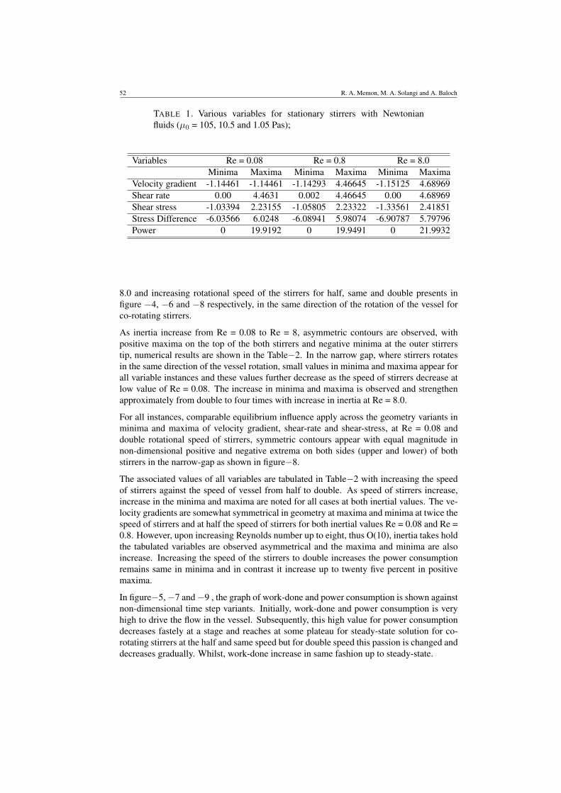
TABLE 1. Various variables for stationary stirrers with Newtonianfluids (µ0 = 105, 10.5 and 1.05 Pas);
Variables Re = 0.08 Re = 0.8 Re = 8.0Minima Maxima Minima Maxima Minima Maxima
Velocity gradient -1.14461 -1.14461 -1.14293 4.46645 -1.15125 4.68969Shear rate 0.00 4.4631 0.002 4.46645 0.00 4.68969Shear stress -1.03394 2.23155 -1.05805 2.23322 -1.33561 2.41851Stress Difference -6.03566 6.0248 -6.08941 5.98074 -6.90787 5.79796Power 0 19.9192 0 19.9491 0 21.9932
8.0 and increasing rotational speed of the stirrers for half, same and double presents infigure −4, −6 and −8 respectively, in the same direction of the rotation of the vessel forco-rotating stirrers.
As inertia increase from Re = 0.08 to Re = 8, asymmetric contours are observed, withpositive maxima on the top of the both stirrers and negative minima at the outer stirrerstip, numerical results are shown in the Table−2. In the narrow gap, where stirrers rotatesin the same direction of the vessel rotation, small values in minima and maxima appear forall variable instances and these values further decrease as the speed of stirrers decrease atlow value of Re = 0.08. The increase in minima and maxima is observed and strengthenapproximately from double to four times with increase in inertia at Re = 8.0.
For all instances, comparable equilibrium influence apply across the geometry variants inminima and maxima of velocity gradient, shear-rate and shear-stress, at Re = 0.08 anddouble rotational speed of stirrers, symmetric contours appear with equal magnitude innon-dimensional positive and negative extrema on both sides (upper and lower) of bothstirrers in the narrow-gap as shown in figure−8.
The associated values of all variables are tabulated in Table−2 with increasing the speedof stirrers against the speed of vessel from half to double. As speed of stirrers increase,increase in the minima and maxima are noted for all cases at both inertial values. The ve-locity gradients are somewhat symmetrical in geometry at maxima and minima at twice thespeed of stirrers and at half the speed of stirrers for both inertial values Re = 0.08 and Re =0.8. However, upon increasing Reynolds number up to eight, thus O(10), inertia takes holdthe tabulated variables are observed asymmetrical and the maxima and minima are alsoincrease. Increasing the speed of the stirrers to double increases the power consumptionremains same in minima and in contrast it increase up to twenty five percent in positivemaxima.
In figure−5, −7 and −9 , the graph of work-done and power consumption is shown againstnon-dimensional time step variants. Initially, work-done and power consumption is veryhigh to drive the flow in the vessel. Subsequently, this high value for power consumptiondecreases fastely at a stage and reaches at some plateau for steady-state solution for co-rotating stirrers at the half and same speed but for double speed this passion is changed anddecreases gradually. Whilst, work-done increase in same fashion up to steady-state.
Analysis of Stresses and Power Consumption of Mixing Flow in Cylindrical Container 53
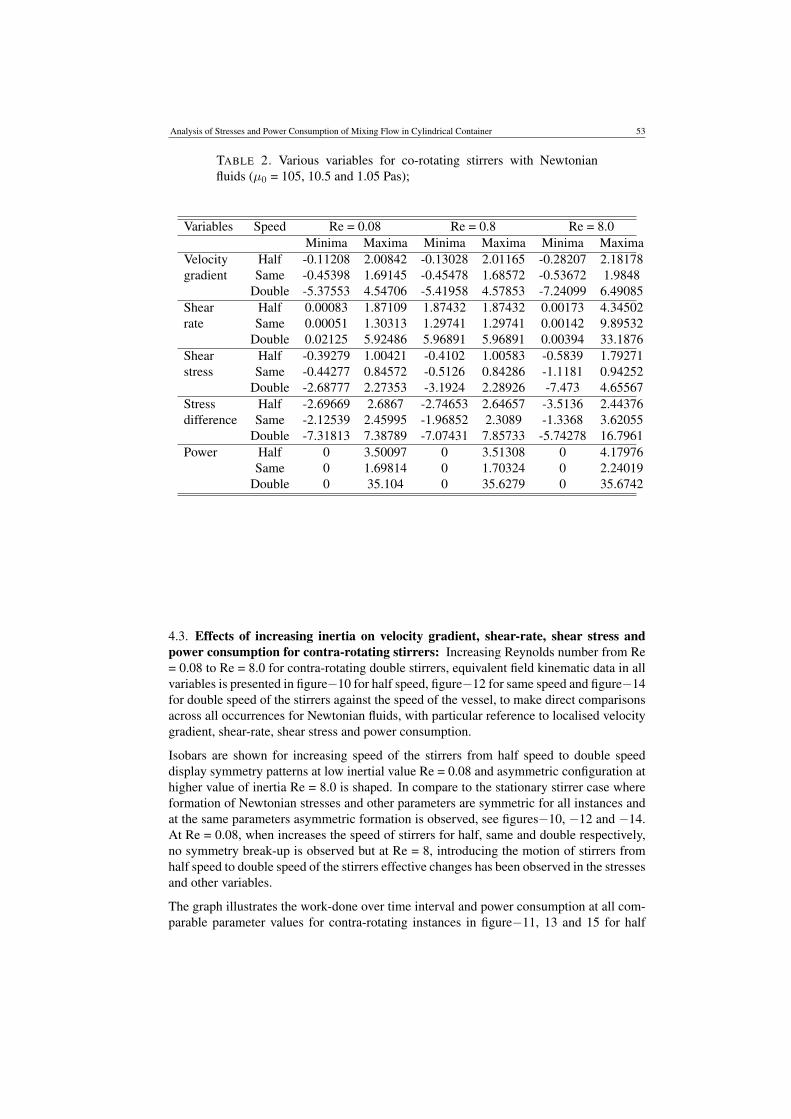
TABLE 2. Various variables for co-rotating stirrers with Newtonianfluids (µ0 = 105, 10.5 and 1.05 Pas);
Variables Speed Re = 0.08 Re = 0.8 Re = 8.0Minima Maxima Minima Maxima Minima Maxima
Velocity Half -0.11208 2.00842 -0.13028 2.01165 -0.28207 2.18178gradient Same -0.45398 1.69145 -0.45478 1.68572 -0.53672 1.9848
Double -5.37553 4.54706 -5.41958 4.57853 -7.24099 6.49085Shear Half 0.00083 1.87109 1.87432 1.87432 0.00173 4.34502rate Same 0.00051 1.30313 1.29741 1.29741 0.00142 9.89532
Double 0.02125 5.92486 5.96891 5.96891 0.00394 33.1876Shear Half -0.39279 1.00421 -0.4102 1.00583 -0.5839 1.79271stress Same -0.44277 0.84572 -0.5126 0.84286 -1.1181 0.94252
Double -2.68777 2.27353 -3.1924 2.28926 -7.473 4.65567Stress Half -2.69669 2.6867 -2.74653 2.64657 -3.5136 2.44376difference Same -2.12539 2.45995 -1.96852 2.3089 -1.3368 3.62055
Double -7.31813 7.38789 -7.07431 7.85733 -5.74278 16.7961Power Half 0 3.50097 0 3.51308 0 4.17976
Same 0 1.69814 0 1.70324 0 2.24019Double 0 35.104 0 35.6279 0 35.6742
4.3. Effects of increasing inertia on velocity gradient, shear-rate, shear stress andpower consumption for contra-rotating stirrers: Increasing Reynolds number from Re= 0.08 to Re = 8.0 for contra-rotating double stirrers, equivalent field kinematic data in allvariables is presented in figure−10 for half speed, figure−12 for same speed and figure−14for double speed of the stirrers against the speed of the vessel, to make direct comparisonsacross all occurrences for Newtonian fluids, with particular reference to localised velocitygradient, shear-rate, shear stress and power consumption.
Isobars are shown for increasing speed of the stirrers from half speed to double speeddisplay symmetry patterns at low inertial value Re = 0.08 and asymmetric configuration athigher value of inertia Re = 8.0 is shaped. In compare to the stationary stirrer case whereformation of Newtonian stresses and other parameters are symmetric for all instances andat the same parameters asymmetric formation is observed, see figures−10, −12 and −14.At Re = 0.08, when increases the speed of stirrers for half, same and double respectively,no symmetry break-up is observed but at Re = 8, introducing the motion of stirrers fromhalf speed to double speed of the stirrers effective changes has been observed in the stressesand other variables.
The graph illustrates the work-done over time interval and power consumption at all com-parable parameter values for contra-rotating instances in figure−11, 13 and 15 for half

54 R. A. Memon, M. A. Solangi and A. Baloch
speed, same speed and double speed of stirrers respectively. The behaviour for all in-stances is same, however, for both Reynolds numbers the comparable values are muchhigher and is almost ten times from half speed to double speed of the stirrers.
The tabulated values are in Table−3, minima and maxima for various variables. For ve-locity gradient, shear-rate, shear-stress and first stress difference between azimuthal andradial stresses, increase in the speed of stirrers from half to double, increase in the minimais observed. At low inertial value, Re = 0.08, this increase is almost double, however, athigher value of inertial, Re = 8, is approximately double to four times increase is noted.Whilst for power consumption is about five times approximately.
TABLE 3. Various variables for contra−rotating stirrers with Newtonianfluids (µ0 = 105, 10.5 and 1.05 Pas);
Variable Speed Re=0.08 Re=0.8 Re=8.0Minima Maxima Minima Maxima Minima Maxima
Velocity Half -2.58992 6.92803 -2.58798 6.92932 -2.43719 7.02753gradient Same -4.01149 9.38669 -4.01449 9.38694 -5.59621 9.5513
Double -6.8582 14.306 -6.90486 14.3229 -11.4476 16.8857Shear Half 0.00089 7.06537 0.00218 7.06665 0.00806 7.16486rate Same 0.00514 9.66136 0.00502 9.66161 0.00408 6.82598
Double 0.01690 14.8553 0.011238 14.8423 0.00481 22.4677Shear Half -1.67833 3.46402 -1.68435 3.46468 -1.74401 3.51377stress Same -2.3286 4.69335 -2.40102 4.69347 -3.21727 8.90697
Double -3.64196 7.153 -3.96812 7.16147 -8.93301 20.743Stress Half -9.38309 9.38414 -9.38008 9.39063 -9.46162 9.56863difference Same -2.7151 12.741 -12.6002 2.8584 -11.7256 15.1497
Double -19.3628 19.4766 -8.8845 20.0245 -16.9897 36.4228Power Half 0 49.9194 0 49.9376 0 51.3353
Same 0 93.3419 0 93.3466 0 96.5495Double 0 220.681 0 221.184 0 289.588
4.4. Effects of increasing inertia on velocity gradient, shear−rate, shear stress andpower consumption for mix−rotating stirrers: For mix-rotating stirrers, the field kine-matics data with increasing Reynolds number from 0.08 to 8.0 with particular reference tolocalised velocity gradient, shear-rate, shear stress and power consumption are shown infigure −16, −18 and −20 for half, same and double speed of stirrers respectively to makedirect comparisons across all instances for Newtonian fluids. For this case, interested phe-nomena arise. In the case of half speed at low inertial value Re = 0.08, isobars are notedin around of the stirrer rotate in same direction of vessel and in right and left of the stirrerrotate in opposite direction of vessel with symmetric pattern in upper and lower region ofvessel. When inertia increase upto Re = 8.0 isobars twist towards the upper region in thedirection of rotation of the vessel. Whenever, situation examines vice-versa in the case ofsame speed of the stirrers.
Isobars are shown for double speed of the stirrers demonstrates symmetry patterns at lowvalue of Reynolds number Re = 0.08 is formed in upper and lower region of the vessel.

Analysis of Stresses and Power Consumption of Mixing Flow in Cylindrical Container 55
TABLE 4. Various variables for mix-rotating stirrers with Newtonianfluids (µ0 = 105, 10.5 and 1.05 Pas);
Variable Speed Re=0.08 Re=0.8 Re=8.0Minima Maxima Minima Maxima Minima Maxima
Velocity Half -0.11208 2.00842 -0.13028 2.01165 -0.28207 2.18178gradient Same -0.45398 1.69145 -0.45478 1.68572 -0.53672 1.9848
Double -5.37553 4.54706 -5.41958 4.57853 -7.24099 6.49085Shear Half 0.004395 4.70657 0.004183 7.41495 0.00363 8.02225rate Same 0.003052 10.3516 0.002647 10.368 0.00142 11.6491
Double 0.026373 16.2418 0.026461 14.2848 0.02993 21.8123Shear Half -2.04905 3.63462 -2.04643 3.63881 -2.11429 3.94246stress Same -4.05551 5.03848 -4.05503 5.04669 -5.24735 5.68721
Double -8.46209 8.15661 -8.48911 8.19283 -21.4674 10.9102Stress Half -9.87923 9.8799 -9.88829 9.89485 -10.742 10.7666difference Same -3.6366 13.6632 -13.5415 13.807 -14.1731 18.239
Double -2.3713 21.4936 -20.8918 22.1177 -20.7601 45.2794Power Half 0 54.8573 0 54.9815 0 64.3564
Same 0 107.156 0 107.496 0 135.701Double 0 263.796 0 265.196 0 405.861
In contrast to the half and same speed of mix-rotating stirrers case where formation ofNewtonian stresses and other parameters are symmetric for all instances, see figures − 20.At Re = 0.08 and for double speed of stirrers, no symmetry break-up is observed. However,at Re = 8, effective has been observed in the stresses and other variables and isobars twisttowards the upper and lower region in the rotational direction of the vessel.
In figure −17, −19 and 21, for mix-rotating instances, graphs illustrate the work-done overtime interval and power consumption at all comparable parameter values. The behaviourfor all instances is same, however, for both Reynolds numbers the comparable values aremuch higher and is almost ten times from half speed to double speed of the stirrers.
Minima and maxima for velocity gradient, shear-rate, shear-stress, first stress differenceand power consumption are tabulated in the Table4, increase in the speed of stirrers fromhalf to double, increase in the minima is observed. At low inertial value, Re = 0.08, thisincrease is almost double, however, at higher value of inertial, Re = 8, is approximatelythree times. Whilst for is about eight times.
5. CONCLUSIONS
The use of a numerical flow simulator as a prediction tool for this industrial flow problemhas been successfully demonstrated. For this complex mixing process, using Newtonianfluid, physically realistic simulations have been provided.
Addressing the rotation of the double stirrer case with stationary stirrers against the threecases of rotating stirrers in co-rotating, contra-rotating and mix-rotating directions are in-vestigated with increasing inertia form Re = 0.08 to Re= 8.0. For stationary stirrers case,it is clearly demonstrated contours of all variables demonstrate symmetric formations in

56 R. A. Memon, M. A. Solangi and A. Baloch
the central region of the vessel, parallel to the stirrers at Re = 0.08 and asymmetric wheninertia reaches at Re = 8.0 and material moves in the direction vessel rotation.
The associated values of all variables for the case of co-rotating stirrers as speed of stirrersincrease, increase in the minima and maxima are noted for all cases at both inertial values.The velocity gradients are somewhat symmetrical in geometry at maxima and minima attwice the speed of stirrers and at half the speed of stirrers for both inertial values variablesare observed asymmetrical and the maxima and minima are also increase. Increasing thespeed of the stirrers to double increases the power consumption remains same in minima.
In the case of contra-rotating Isobars are shown for half speed to double speed displaysymmetry patterns at low inertial value and asymmetric configuration at higher value ofinertia. When increases the speed of stirrers from half to double, no symmetry break-up isobserved but at higher inertia, introducing the motion of stirrers from half speed to doublespeed of the stirrers effective changes has been observed in the stresses and other variables.
Minima and maxima for velocity gradient, shear-rate, shear-stress, first stress differenceand power consumption in the case of mix-rotating stirrers, increase in the speed of stirrersfrom half to double, increase in the minima is observed. At low inertial value, Re = 0.08,this increase is almost double, however, at higher value of inertial, Re = 8, is approximatelythree times.
Through the predictive capability generated, we shall be able to relate this to mixer designthat will ultimately impact upon the processing of dough products. Promising future direc-tions of this work are investigation of rotation of two stirrers case in co-rotating, contra-rotating and mix-rotating directions, changing material properties using non-Newtonianfluids and further introducing agitator in concentric configured stirrers in future.
Acknowledgement
The authors are greatly acknowledged to the Mehran University of Engineering and Tech-nology, Jamshoro, for providing computational facility and financial grant of Higher Edu-cation Commission of Pakistan.
REFERENCES
[1] K. S. Sujatha, M. F.Webster, D. M. Binding, M. A. Couch, Modelling and experimental studies of rotatingflows in part-filled vessels: wetting and peeling, J. Foods Eng., 57, (2002), 67−79.
[2] D. M. Binding, M. A. Couch, K. S. Sujatha, M. F. Webster, Experimental and numerical simulation ofdough kneading in filled geometries, J. Foods Eng.57, (2002) 1−13.
[3] K. S. Sujatha,, D. Ding, M. F. Webster, Modelling three-dimensions mixing flows in cylindrical-shapedvessels, in: ECCOMAS CFD - 2001, Swansea, UK, (2001) 1−10.
[4] K. S. Sujatha,, D. Ding, M. F. Webster, Modelling of free surface in two and three dimensions, in: C. A.Brebbia, B. Sarlen (Eds.), Sixth International Conference on Computational Modelling of Free and MovingBoundary Problems - 2001, WIT, Lemnos, Greece, (2001) 102−111.
[5] D. Ding, M. F. Webster, Three-dimensional numerical simulation of dough kneading, in: D. Binding, N.Hudson, J. Mewis, J.-M. Piau, C. Petrie, P. Townsend, M. Wagner, K. Walters (Eds.), XIII Int. Cong. onRheol., Vol. 2, British Society of Rheology, Cambridge, UK, (2000) 318−320.
[6] N. Phan-Thien, M. Newberry and R. I. Tanner, Non-linear oscillatory flow of a solid-like viscoelastic mate-rial, J. Non-Newtonian Fluid Mech., 92, (2000) 67−80.
[7] P. M. Portillo, F. J. Muzzio and M. G. Ierapetritou, Hybrid DEM-Compartment Modelling Approach forGranular Mixing, AIChE Journal, 53(1), (2007) 119−128.

Analysis of Stresses and Power Consumption of Mixing Flow in Cylindrical Container 57
[8] A. Baloch, P. W. Grant and M. F. Webster, M. F., Parallel Computation of Two-Dimensional RotationalFlows of the Viscoelastic Fluids in Cylindrical Vessel, Int. J. Comp. Aided Eng. and Software, Eng. Comput.,19(7), (2002) 820−853.
[9] A. Baloch, G. Q. Memon, and M. A. Solangi, Simulation of Rotational Flows in Cylindrical Vessel withRotating Single Stirrer, Punjab University Journal of Mathematics, 40, (2008) 83−96.
[10] A. Baloch, and M. F. Webster, M. F., Distributed Parallel Computation for Complex Rotating Flows ofNon-Newtonian Fluids, Int. J. Numer. Meth. Fluids, 43, (2003) 1301−1328.
[11] P. Townsend and M. F. Webster, An algorithm for the three-dimensional transient simulation of non-Newtonian fluid flows, in: G. Pande, J. Middleton (Eds.), Proc. Int. Conf. Num. Meth. Eng.: Theory andApplications, NUMETA, Nijhoff, Dordrecht, T12 (1987) 1−11.
[12] D. M. Hawken, H. R. Tamaddon-Jahromi, P. Townsend, M. F. Webster, A Taylor-Galerkin-based algorithmfor viscous incompressible flow, Int. J. Num. Meth. Fluids, 10, (1990) 327−351.

58 R. A. Memon, M. A. Solangi and A. Baloch
Re = 0.08
Re = 8.0
FIGURE 2. Contour plots of Velocity gradient, Shear-rate, Shear stressand Power for stationary stirrers for Newtonian fluid with increasingReynolds number.
FIGURE 3. Graphs of power and work done for stationary stirrers forNewtonian fluid with increasing Reynolds number.

Analysis of Stresses and Power Consumption of Mixing Flow in Cylindrical Container 59
Re = 0.08
Re = 8.0
FIGURE 4. Contour plots of Velocity gradient, Shear-rate, Shear stressand Power for co-rotating stirrers with half speed for Newtonian fluidwith increasing Reynolds number.
FIGURE 5. Graphs of power and work done for co-rotating stirrers withhalf speed for Newtonian fluid with increasing Reynolds number.

60 R. A. Memon, M. A. Solangi and A. Baloch
Re = 0.08
Re = 8.0
FIGURE 6. Contour plots of Velocity gradient, Shear-rate, Shear stressand Power for co-rotating stirrers with same speed for Newtonian fluidwith increasing Reynolds number.
FIGURE 7. Graphs of power and work done for co-rotating stirrers withsame speed for Newtonian fluid with increasing Reynolds number.

Analysis of Stresses and Power Consumption of Mixing Flow in Cylindrical Container 61
Re = 0.08
Re = 8.0
FIGURE 8. Contour plots of Velocity gradient, Shear-rate, Shear stressand Power for co-rotating stirrers with double speed for Newtonian fluidwith increasing Reynolds number.
FIGURE 9. Graphs of power and work done for co-rotating stirrers withdouble speed for Newtonian fluid with increasing Reynolds number.

62 R. A. Memon, M. A. Solangi and A. Baloch
Re = 0.08
Re = 8.0
FIGURE 10. Contour plots of Velocity gradient, Shear-rate, Shear stressand Power for contra-rotating stirrers with half speed for Newtonian fluidwith increasing Reynolds number.
FIGURE 11. Graphs of power and work done for contra-rotating stirrerswith half speed for Newtonian fluid with increasing Reynolds number.
Analysis of Stresses and Power Consumption of Mixing Flow in Cylindrical Container 63
Re = 0.08
Re = 8.0
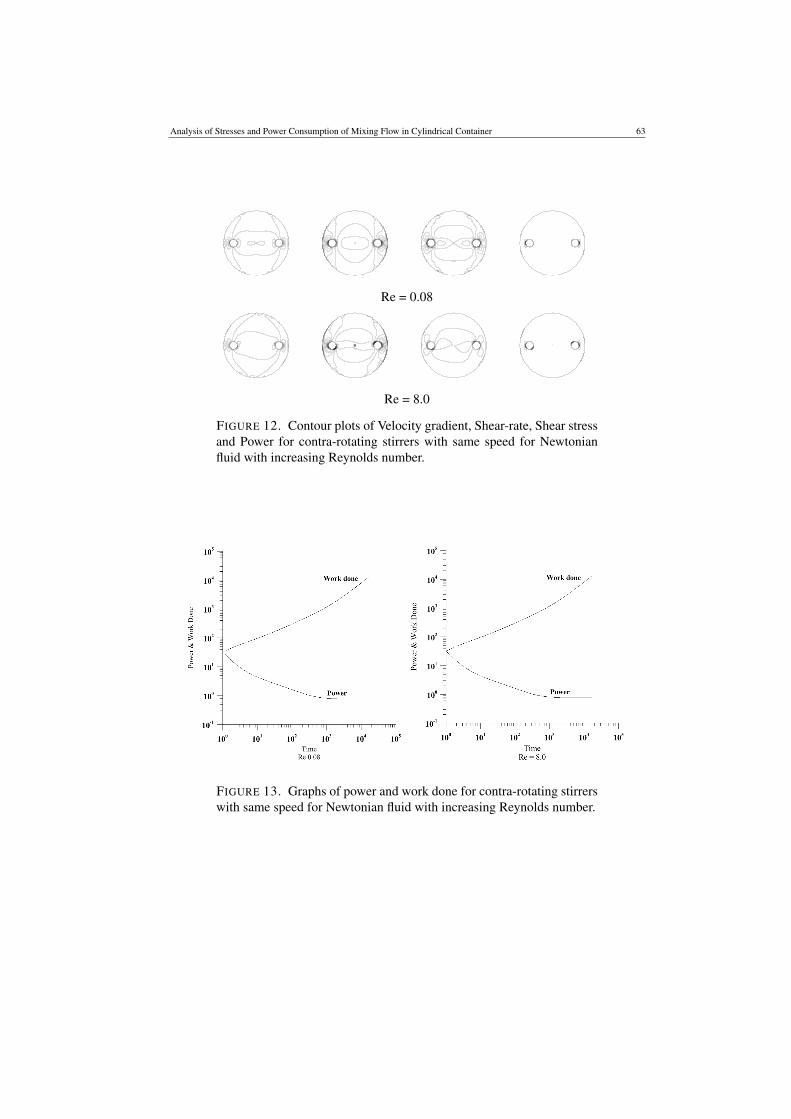
FIGURE 12. Contour plots of Velocity gradient, Shear-rate, Shear stressand Power for contra-rotating stirrers with same speed for Newtonianfluid with increasing Reynolds number.
FIGURE 13. Graphs of power and work done for contra-rotating stirrerswith same speed for Newtonian fluid with increasing Reynolds number.
64 R. A. Memon, M. A. Solangi and A. Baloch
Re = 0.08
Re = 8.0
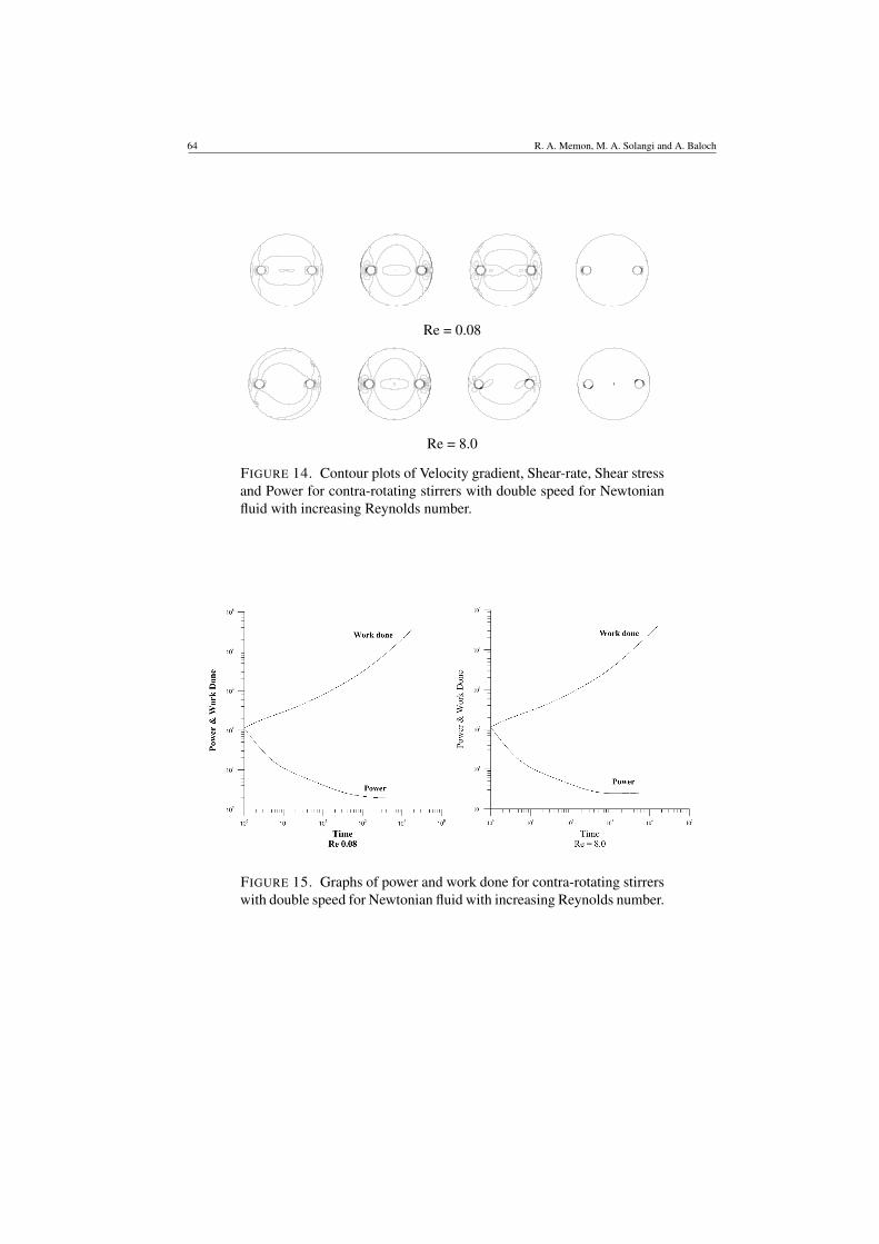
FIGURE 14. Contour plots of Velocity gradient, Shear-rate, Shear stressand Power for contra-rotating stirrers with double speed for Newtonianfluid with increasing Reynolds number.
FIGURE 15. Graphs of power and work done for contra-rotating stirrerswith double speed for Newtonian fluid with increasing Reynolds number.

Analysis of Stresses and Power Consumption of Mixing Flow in Cylindrical Container 65
Re = 0.08
Re = 8.0
FIGURE 16. Contour plots of Velocity gradient, Shear-rate, Shear stressand Power for mix-rotating stirrers with half speed for Newtonian fluidwith increasing Reynolds number.
FIGURE 17. Graphs of power and work done for mix-rotating stirrerswith half speed for Newtonian fluid with increasing Reynolds number.

66 R. A. Memon, M. A. Solangi and A. Baloch
Re = 0.08
Re = 8.0
FIGURE 18. Contour plots of Velocity gradient, Shear-rate, Shear stressand Power for mix-rotating stirrers with same speed for Newtonian fluidwith increasing Reynolds number.
FIGURE 19. Graphs of power and work done for mix-rotating stirrerswith same speed for Newtonian fluid with increasing Reynolds number.

Analysis of Stresses and Power Consumption of Mixing Flow in Cylindrical Container 67
Re = 0.08
Re = 8.0
FIGURE 20. Contour plots of Velocity gradient, Shear-rate, Shear stressand Power for mix-rotating stirrers with double speed for Newtonianfluid with increasing Reynolds number.
FIGURE 21. Graphs of power and work done for mix-rotating stirrerswith double speed for Newtonian fluid with increasing Reynolds number.