analyzing the behavior of a hybrid steel to timber
TRANSCRIPT

Master’s Thesis 2017 30 ECTS
Faculty of Science and Technology
Analyzing the behavior of a hybrid
steel to timber connection by
modifying different parameters.
Youcef Amara and Samuel Embaye
Insert Study programme (Arial, regular, 11pt)


Preface and acknowledgements
This master thesis is written in the spring semester of 2017 at the Faculty of Science and
Technology at the Norwegian University of Life Science (NMBU). It is the final work of a 2-year
master’s degree in Building technique and Architecture. The supervisor through the semester has
been Associate Professor Themistoklis Tsalkatidis.
The goal of this thesis is to analyse the behaviour of a hybrid connection between a tubular steel
column and a glulam beam, that are connected together with top and seat angles by the means of
bolts. Different parameters are examined in order to capture the exact physical behaviour of the
connection and to monitor the effect of each alteration. This type of hybrid connection has not
been thoroughly examined in the past, especially in relation to changing several different
parameters in order to have a simulation as realistic as possible. This is the main contribution of
the presented thesis.
The major part of this thesis has been spent on modelling the connections. Many different scripts
have been written and changed multiple times in order to achieve an accurate model. The authors
have limited experience in contact problems and use of a finite element software, so the learning
curve had to increase abruptly.
We would like to sincerely thank our supervisor, Associate Professor Themistoklis Tsalkatidis, for
his guidance,support and ongoing positive attitude towards our thesis throughout the past semester.
We have learned a lot by working on the hybrid connection and the topic was proven to be an
excellent choice that gave us more insight about contact finite element problems. We would also
like to thank Alejandro Figueres for his opinions and thoughts on the different obstacles that we
ran into throughout the semester. Finally, we want to thank our families for their patience and for
their understanding for all the late nights spent at the university working on our thesis.
II
Sammendrag Det er ikke forsket like mye på knutepunkt mellom stål og tre, som det er forsket på knutepunkt mellom
stål og betong. Ved å kombinere styrken til stål med den lave vekten til tre, får vi et miljøvennlig knutepunkt
som kan være med å bidra betraktelig til et knutepunkt for fremtiden.
Ved å starte med teoretisk bakgrunn presenterer denne masteroppgaven prosessen ved å modellere et
knutepunkt og dets tilhørende parametere. Det legges vekt på bruken av viktige parametere of effekten av
å endre disse parameterne i knutepunktet. En numerisk modell ble laget og verifisert slik at denne er
troverdig. Normalt utføres det et eksperiment før det lages en numerisk modell slik at denne kan bli
verifisert, men på grunn av mangel på ressurser her på universitetet kunne dette ikke utføres. Derfor fant vi
etter søk på internasjonal litteratur, en publisert studie som vi har valgt å bruke som verifikasjon. Et av
knutepunktene som er eksperimentelt testet i dette studiet er valgt som den grunnleggende knutepunkts
modellen som har blitt numerisk analysert i denne oppgaven. Sammenligningen mellom eksperimentet og
den numeriske modellen`s resultater er grunnlaget for verifiseringen av den numeriske modellen. Etter at
verifiseringen har blitt gjort har flere parametere fra den opprinnelige modellen blitt forandret slik at det
kan analyseres hvor stor effekt disse forandringene har. Flere knutepunktsmodeller har blitt undersøkt og
en optimal sammensetning har blitt funnet, og dette er sannsynligvis hovedbidraget fra denne
masteroppgaven
Analysene har blitt gjort med bruk av skripting i Finite-element programmet Ansys Mechanical APDL.
Dette er et avansert program som krever at enhver parameter er korrekt for å kunne produsere nøyaktige
resultater. Den opprinnelige modellen består av vinkler med 15mm tykkelse som er montert oppe og nede
på limtrebjelken med 12mm gjennomgående bolter, og 16mm bolter som kobler vinklene sammen til
stålsøylen. Totalt ble syv knutepunktsmodeller undersøkt og det optimale knutepunktet besto av en
kombinasjon a to forskjellige knutepunktsmodeller. Det ble funnet ut at ved å kombinere 20mm vinkler
både oppe og nede på limtrebjelken, sammen med 20mm gjennomgående bolter ville rotasjonsstivheten
øke markant med 137% ,mens von Mises stress vil synke med 20.2%

III
Abstract
The behaviour of hybrid connections between timber and steel has not been investigated as
extensively as the connections between concrete and steel. By combining the strength of steel with
the low weight of timber, an environment friendly connection is constructed and this option may
be the rule for structural connections in the future.
By starting with theoretical background, this thesis presents the process of modelling a connection
and the related parameters. It emphasizes on the use of important parameters and the effect of
changes in these parameters on the connection. A base numerical model was constructed and
verified, in order for this to be reliable. Normally an experimental analysis is done before
developing a numerical model, so the latter can be verificated, but due to lack of resources at the
university, an experiment could not be done. Therefore, after searching the international literature,
a research paper has been selected. A connection tested in this paper was selected as the base
connection that was numerically analysed in this thesis. Moreover, the comparison between
experimental and numerical results lead to the verification of the numerical model. After the
verification was made, many different parameters of the base connection were altered in order to
analyse and quantify the effect of these changes. Many case studies were examined. An optimal
configuration has been found and this is probably the main contribution of the current thesis.
The analyses were done with scripting, using the Finite element program Ansys Mechanical
APDL. This is a complex detailed program that needs every parameter to be correct in order to
produce accurate results. The base model consists of 15mm thick top and seat angle connected
with 12mm bolts that runs through the glulam beam and 16mm bolts connected to the tubular steel
column. Together with the base model, a total of seven case studies have been investigated whereas
the optimal connection was found to be a combination of two cases. It was found that by
combining a 20 mm thick top and seat angle and 20 mm vertical bolts the rotational stiffness of
the connection increased significantly with 137%, while the von Mises stress in the top angle was
reduced by as much as 20.2%.

IV
Content 1 Introduction 1
1.1 Background 1
1.2 Area of focus 1
1.3 Limitations 2
2 Theory 3
2.1 Glulam 3
2.2 Steel 6
2.3 Connections 7
2.3.1 The moment-rotation relationship 8
2.3.2 Component based method 9
2.3.3 Classification of connections by stiffness 10
2.3.4 Classification of connections by strenght 13
2.4 Bolted connection 14
2.5 Finite element method 16
3 Finite Element Model 18
3.1 Ansys Mechanical APDL 18
3.2 Model parameters 19
3.2.1 Element type 19
3.2.2 Contact 21
3.2.2.1 Contact elements 22
3.2.2.2 Target elements 23
3.2.2.3 Symmetric and asymmetric pairs 25
3.2.2.4 Contact analysis type 26
3.2.2.5 Contact method 27
3.2.3 Contact properties 27
3.2.3.1. Contact surface behavior 28
3.2.3.2 Contact detection 29
3.2.3.3 Normal penalty stiffness 30
3.2.3.4 Penetration tolerance 30
3.2.3.5 Pinball region 30
3.2.3.6 Coulomb’s friction 31

V
3.2.4 Contact Algorithm 31
3.2.4.1 The penalty method 31
3.2.4.2 The Augmented Lagrange method 31
3.2.4.3 The pure Lagrange multiplier method 32
3.2.4.4 Multipoint constraint algorithm 32
3.3 Equation solver 32
3.3.1 The sparse direct solver 34
3.3.2 The Preconditioned conjugate gradient (PCG) 34
3.3.3 The Jacobi conjugate gradient solver 35
3.3.4 The Incomplete Cholesky Conjugate Gradient Solver 35
3.4 Newton-Raphson procedure 35
3.5 Pretension 37
3.6 MESH 38
4 Numerical Modelling 40
4.1 Scripting in Ansys 40
4.2 Connection description 40
4.3 Assumptions and simplifications 42
4.4 Contact parameters used in ANSYS APDL 44
4.4.1 Element type 44
4.4.2 Contact and target elements 44
4.4.3 Contact analysis type 45
4.4.4 Contact surface behavior 45
4.4.5 Friction 45
4.4.4 Contact algorithm 46
4.4.5 Equation solvers 46
4.5 External loading, pretension, and boundary conditions 46
4.6 Singularities 48
4.7 Model validations 48
4.8 Case studies 50
4.8.1 Moment rotation 51
4.8.2 von Mises stress 52
4.8.3 Initial rotational stiffness 52
5 Results 55

VI
5.1 Case 1 55
5.2 Case 2 59
5.3 Case 3 63
5.4 Case 4 68
5.5 Case 5 72
5.6 Case 6 76
5.7 Case 7 81
5.8 Initial stiffness of connections 85
6 Discussion 86
6.1 Effect of changing the angle thickness 86
6.2 Effect of changing the diameter of the bolts connected to the beam 87
6.3 Effect of reducing the width of the angles 87
6.4 Effect of using a stiffener in the top angle 87
6.5 Seat angles 88
6.6 Wood failure 88
6.7 Vertical bolts 89
6.8 Initial rotational stiffness 89
7 Conclusion 91

VII
List of Figures
Figure 2.1. Glued-laminated timber manufacturing process………………………………….................4
Figure 2.2.frequency distribution of the ultimate strength of glulam and structural timber:....................5
Figure 2.3. Stress-strain relationship………………………………………………………………….....6
Figure 2.4. Different classes of connections………………………………………………......................8
Figure 2.5 Possible idealizations for M-Ø curves…………………………………..................................9
Figure 2.6. Connection stiffness in M-Ø curve….……………………………………………………...11
Figure 2.7 Schematization of rotational stiffness………………………………………………………12
Figure 2.8 Moment rotation curve according to strength…………………………………………….....13
Figure 2.9 Load transfer in non-preloaded bolt………………………………………………………...15
Figure 2.10. Load transfer in preloaded bolt ………………………………………………...................15
Figure 3.1 Modules in Ansys………………………………………………….…………………..........18
Figure 3.2 Element geometry SOLID185 ………………………………………………………..........20
Figure 3.3 Element geometry SOLID186 ……………………………………………….....................20
Figure 3.4 Element geometry SOLID187……………………………………………………………....21
Figure 3.5 CONTA173 ………………………………………………………………………………...22
Figure 3.6 CONTA174…………………………..………………………………………………..........23
Figure 3.7 Functionality of the target elements…………………………………….…………………..24
Figure 3.8 Principals of the target elements……………………………………………...…………….24
Figure 3.9 Schematic representation of symmetric and asymmetric contact…………………………..26
Figure 3.10 Contact detection at Gauss point………………………..……………………………........29
Figure 3.11 Contact detection at Nodal detection……………………………..……...………………..29
Figure 3.12 First iteration in Newton-Raphson procedure.…………………………..……………….36
Figure 3.13 second iteration in Newton-Raphson procedure………...………………………….........37
Figure 3.14 Tension after adjustments…………………………...…………………………………….38
Figure 3.15 fine vs coarse mesh… …………………………..…….……………………………….....39
Figure 3.16 free vs mapped mesh…… …………......………………...……………………………….39
Figure 4.1 Abaqus vs. Ansys Model ………………………………………….………………………..41
Figure 4.2 Top and seat angle………………………………………………..…………………………42
Figure 4.3 Behaviour of angle ………………………………………………………………………….43
Figure 4.4 Constraining the column………………………………………………………………….....47
Figure 4.5 Verification of the model………………………..…………………...……...........................49

VIII
Figure 4.6 Deflection in the top angle with and without stiffener……………………….......................52
Figure 5.1 The moment-rotation curve in case 1……………………………...………………………...55
Figure 5.2 von Mises stress in the top angle in case 1……..…………………...…….............................56
Figure 5.3 von Mises stress in the seat angle in case 1……..…………………...……............................57
Figure 5.4 Stress perpendicular to the glulam beam at the first load step in case 1…………………….57
Figure 5.5 Stress perpendicular to the glulam beam at the second load step in case 1………………….58
Figure 5.6 von Mises stress in the vertical bolts in case 1…….…………………….…………………..58
Figure 5.7 Comparison of moment-rotation curves.……………….………..…...……………………...59
Figure 5.8 von Mises stress in the top angle in case 2………………………………..……....………....60
Figure 5.9 von Mises stress in the seat angle in case 2……………………....………….........................61
Figure 5.10 Stress perpendicular to the glulam beam at the first load step in case 2………...................61
Figure 5.11 Stress perpendicular to the glulam beam at the second load step in case 2...……..………..62
Figure 5.12 von Mises stress in the vertical bolts in case 2………………………..………...……….....62
Figure 5.13 Comparison of moment-rotation curves………………..………...………………………...64
Figure 5.14 von Mises stress in the top angle in case 3……………....……………...………………….65
Figure 5.15 von Mises stress in the seat angle in case 3………………….………………...…………..65
Figure 5.16 Stress perpendicular to the glulam beam at the first load step in case 3....………………..66
Figure 5.17 Stress perpendicular to the glulam beam at the second load step in case 3.....…..………...66
Figure 5.18 von Mises stress in the vertical bolts in case 3……...………………...…………………....67
Figure 5.19 von Mises stress in the top angle in case 4…………………..…………...……..................69
Figure 5.20 von Mises stress in the seat angle in case 4……………..…………...……..................,......69
Figure 5.21 Stress perpendicular to the glulam beam at the first load step in case 4...………………....70
Figure 5.22 Stress perpendicular to the glulam beam at the second load step in case 4...……...……...70
Figure 5.23 von Mises stress in the vertical bolts in case 4……………….……….……...…………....71
Figure 5.24 Comparison of moment-rotation curves……….…………………...…................................72
Figure 5.25 von Mises stress in the top angle in case 5……….…………………...…............................73
Figure 5.26 von Mises stress in the seat angle in case 5……….…………………...…..........................74
Figure 5.27 Stress perpendicular to the glulam beam at the first load step in case 5……….…………..74
Figure 5.28 Stress perpendicular to the glulam beam at the second load step in case 5…….…………..75
Figure 5.29 von Mises stress in the vertical bolts in case 5…….…………………...…..........................75
Figure 5.30 Comparison of moment-rotation curves……….…………………...…...............................77
Figure 5.31 von Mises stress in the top angle in case 6…….…………………...…................................78
Figure 5.32 von Mises stress in the seat angle in case 6…….…………………...…...............................78
Figure 5.33 Stress perpendicular to the glulam beam at the first load step in case 6..……………….....79

IX
Figure 5.34 Stress perpendicular to the glulam beam at the second load step in case 6…….………….79
Figure 5.35 von Mises stress in the vertical bolts in case 6…….…………………...…..........................80
Figure 5.36 Comparison of moment-rotation curves……….…………………...…................................81
Figure 5.37 von Mises stress in the top angle in case 7…….…………………...…................................82
Figure 5.38 von Mises stress in the seat angle in case 7…….…………………...…...............................83
Figure 5.39 Stress perpendicular to the glulam beam at the first load step in case 7...............................83
Figure 5.40 Stress perpendicular to the glulam beam at the second load step in case 7..........................84
Figure 5.41 von Mises stress in the vertical bolts in case 7….…………………...…..............................84

X
List of tables
Table 1 Mechanical Properties for glulam GL28h………………………………..................................42
Table 2 Distances between the bolts and the edges………………………………..…………………...42
Table 3 Pretension calculated from given torque……………………………....………………………47
Table 4 Stress values taken from experimental test…………………….………………........................49
Table 5 Case studies ……………………………………………...……………………........................50
Table 6 Moment rotation at different load steps for case 1……………………......................................55
Table 7 von Mises stress for top angle at different coordinates for case 1……………………..............56
Table 8 Moment rotation at different load steps for case 2……………………………..........................59
Table 9 von Mises stress for top angle at different coordinates for case 2……………………………...60
Table 10 von Mises comparison between case 1 and case 2……………………………………………63
Table 11 Moment rotation at different load steps for case 3………………………………....................63
Table 12 von Mises stress for top angle at different coordinates for case 3………………..…………...64
Table 13 von Mises comparison between case 1 and case 3…………………………………................67
Table 14 Moment rotation at different load steps for case 4……………………………....……………68
Table 15 von Mises stress for top angle at different coordinates for case 4...…………..........................68
Table 16 von Mises comparison between case 1 and case 4…………………………….……………..71
Table 17 Moment rotation at different load steps for case 5 ……………………………..…................72
Table 18 von Mises stress for top angle at different coordinates for case 5………………..…………..73
Table 19 von Mises comparison between case 1 and case 5…………………………..……………….76
Table 20 Moment rotation at different load steps for case 6………………………..………………….76
Table 21 von Mises stress for top angle at different coordinates for case 6………….............................77
Table 22 von Mises comparison between case 1 and case 6……………………………………………80
Table 23 Moment rotation at different load steps for case 7……………………………………………81
Table 24 von Mises stress for top angle at different coordinates for case 7……………...……………..82
Table 25 Initial stiffness of connections………………………………………………...........................85
Table 26 von Mises comparison between case 1 and the combined case..……………...........................90

XI
Symbols and Terminology
Kh Size-effect factor for glulam strength
h Height of the beam.
Rm Ultimate tensile stress of the steel
Rp 0,2 Upper yield stress of the steel (0.2%)
Rp 0,01 Lower yield stress of the steel (0.01%)
Sj,ini Initial rotational stiffness
Sj Rotational stiffness
Kb Mean value of lb/Lb for every beam in the top story
Kc Mean value of Ic/Lc for all columns in that story
Ib Beam's second moment of inertia
Ic Column`s second moment of inertia
Lb Span of the beam
EIb Bending stiffness of the beam
MRd Design moment resistance of the connection
Mpl.Rd Design strength of the beam .
Ki Stiffness coefficient for every component
Z Lever arm of the beam
μ Stiffness ratio
Ma Applied torque
d Bolt diameter
Fp Preloaded in the bolt
k Coefficient of friction between mating surface
S Local connection force
К Stiffness matrix for the element
v Displacement matrix for the element
R Global connection force
K Global stiffness matrix

XII
R Connection displacement
U Global vector of unknown displacement
F Applied global load vector
L Lower triangular matrix
u Upper triangular matrix
Fa Applied loads
KiT Jacobian matrix
Finr Vector of restoring loads corresponding to the element internal loads.
db Depth of the glulam beam
Δe Elastic deformation
Ø Rotation of the connection
le Effective length of the angle
M Moment in connection
Pe Reaction force
Kcf Bearing stiffness of the column face
tc Thickness of the wall of the column
ν Poisson's ratio for steel
bc Width of the column face
Kt Stiffness in the horizontal leg of the angle
p Width of the angles
Thickness of the angle
a` Distance from the inner bolt hole to the vertical leg of the angles
Ksb Stiffness of the bolt
Ab Area of the bolt
Lb Length of the bolt subjected to axial tension
KTOP Stiffness of the top angle
KBOTTOM Stiffness of the seat angle
1 Introduction
1.1 Background
Over the years hybrid connections between steel and concrete have been studied and widely
investigated. The study however on the hybrid connections between timber and steel is less
common, even though these types of hybrid connections have proven to offer some advantages
over the more commonly used steel to concrete connections.
In Norway the access to timber is very high, but unfortunately the behavior of different connection
types using steel and timber has not been investigated extensively. Therefore, a contribution of
this thesis is to expand the current knowledge by analyzing this type of hybrid connection.
Different types of steel to timber connections exist, but the focus in this thesis is on one specific
interesting connection. The chosen connection is between a tubular steel column and a glulam
beam connected together with top and seat angles by the means of bolts. This connection has not
been extensively studied in the past and the optimization of it is something of which little to no
studies have been done. Therefore, the connection is examined while several different parameters
that affect its behavior are modified.
1.2 Area of focus
The area of focus in this thesis is the connection between a tubular steel column and a glulam
beam. The angle brackets, bolts, and the glulam beam itself are under the scope, but a closer
analysis of the top angle has been made. After extensive research, the main topic of this thesis can
be written as follow: ”Translate the results of several analyses where the change of different
parameters is examined within a connection between a tubular steel column and a glulam beam”.
Several important subtopics need to be investigated:
How does changes in the angles affect the behavior of the connection?
2
How does changes in bolts affect the behavior of the connection?
What are the effects of introducing stiffeners to the connection?
1.3 Limitations
Modelling a connection between steel and timber with top and seat angles that are connected by
the means of bolts, is a complex procedure. Many parameters need to be correct in order for the
analyses to be more accurate, or at least to get fairly accurate results from the FE-software. Because
of the time frame and the complexities related to a detailed analysis of a hybrid connection of such
a type, the following limitations and assumptions have been implemented:
● The shear force in the connection has not been taken into consideration
● Wood crushing has been observed, but it was not the main scope of this thesis
● Plastic behavior was also outside the scope of this thesis
● The behavior of the column and the blind bolts have not been taken into
consideration
This is due to the fact that the connection between the steel angles and the glulam beam is of
primary interest.
3
2 Theory
2.1 Glulam
Introduction
Timber is one of the oldest and most sustainable construction materials which has a high number
of excellent mechanical properties. The strength to weight ratio is very high. Timber is an
environmental friendly material and it can easily be shaped and connected. In addition, timber has
good insulating properties against heat and sound. Nevertheless, it also has some weak mechanical
properties if it is not properly treated. Since timber is an anisotropic material, the strength and
stiffness perpendicular to the grain is much lower than the one that is parallel to the fiber direction.
The swelling and shrinking perpendicular to grain, at varying moisture contents, makes timber
vulnerable to cracking. The mechanical properties of timber depends on the microstructure of the
wood. [12]
Structural glued-laminated timber (glulam) is one of the competitive products used in
constructions today. Glulam is manufactured by gluing timber boards parallel to the longitudinal
axis together and end-jointing individual wood pieces to the desired shape. The thickness of
laminates ranges from 19-50 mm and has a length between 1.5-5m. For straight or slightly curved
members, timber boards with thickness 33mm or above are used as laminates. Due to small
variability in strength, glulam has greater strength and stiffness properties when compared with
structural timber. Although almost any type of wood species can be used for glulam, softwoods
are more preferable due to adhesive properties. Figure 2.1 shows the production process of glue-
laminated timber. [13]

4
Figure 2.1. Glued-laminated timber manufacturing process
Strength and stiffness
The strength of glulam depends on the angle between the load and grain, the moisture content and
the duration of loading. In production process the factors that affect the strength of the structural
timber like knots are either removed or more uniformly distributed in the finished production. This
makes the glulam stronger than the normal structural timber. The comparison of the frequency in
the ultimate strength for glulam and structural timber are presented in figure 2.2. The strength of
structural timber depends on the weakest cross-section. If there is a knot or a crack in the board’s
cross section, the strength is reduced considerably. Since there are several laminates which are
glued together, the risk of having a weak section in glulam is lower. Due to these differences the
material factor for glulam in designing is 1.25, which is lower than 1.3 which is the material factor
for structural timber.
Laboratory results indicate that glulam beams experience a very brittle failure due to the existence
of knot or finger joints when the beam is subjected to tension. The characteristic tensile strength
parallel to the grain relates to members with a minimum width of 600mm and a minimum thickness
of 150mm. The risk of failure increases as the volume of the beam increases. Therefore the

5
strength of thicker beams tends to be lower than that of thinner beams. According to Eurocode-5,
the size-effect factor (Kh) that increases in bending and tensile strength for beams with height less
than 600mm is given by the following factor: [13]
(2.1)
Where
Kh is the size-effect factor
h is the height of the beam.
Since glulam is strong compared to its self-weight, it can be used for wide spans with minimal
supports.
Figure 2.2. Frequency distribution of the ultimate strength of glulam and structural timber
6
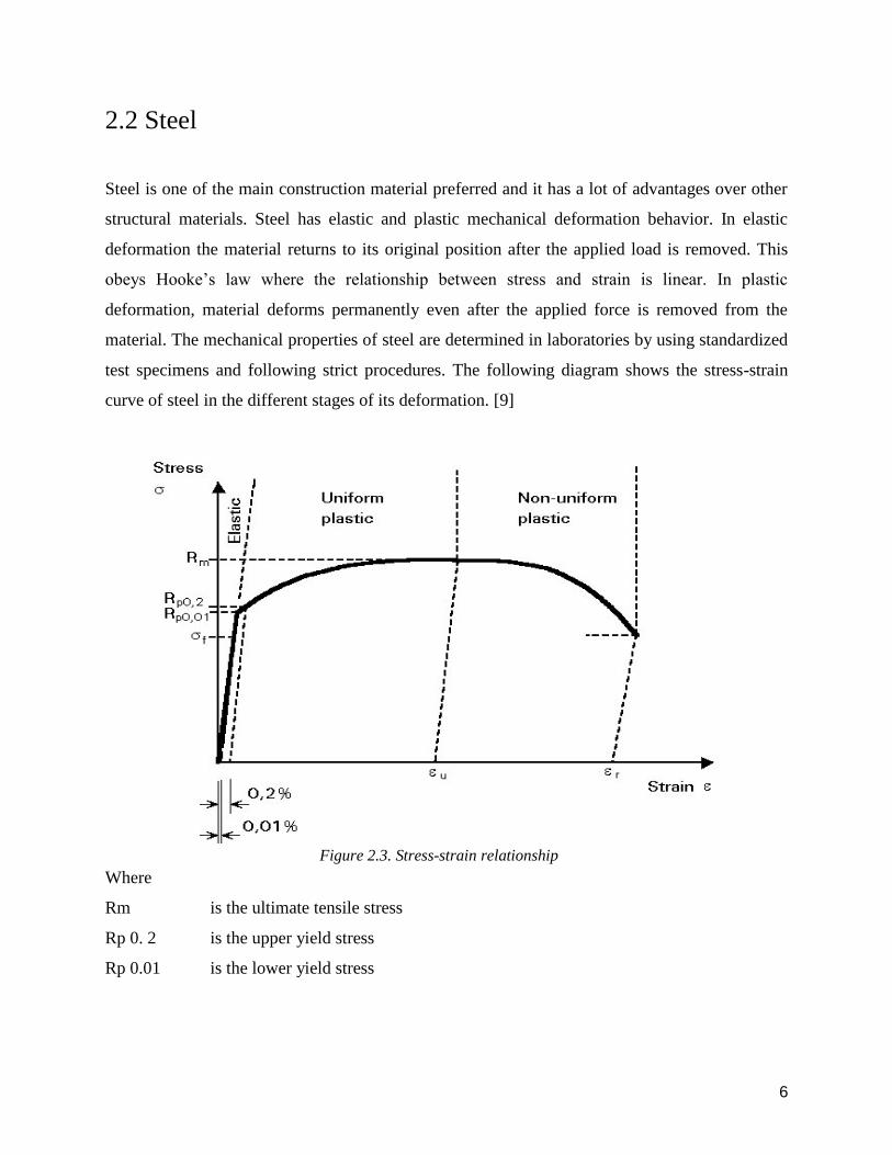
2.2 Steel
Steel is one of the main construction material preferred and it has a lot of advantages over other
structural materials. Steel has elastic and plastic mechanical deformation behavior. In elastic
deformation the material returns to its original position after the applied load is removed. This
obeys Hooke’s law where the relationship between stress and strain is linear. In plastic
deformation, material deforms permanently even after the applied force is removed from the
material. The mechanical properties of steel are determined in laboratories by using standardized
test specimens and following strict procedures. The following diagram shows the stress-strain
curve of steel in the different stages of its deformation. [9]
Figure 2.3. Stress-strain relationship
Where
Rm is the ultimate tensile stress
Rp 0. 2 is the upper yield stress
Rp 0.01 is the lower yield stress

7
In structural engineering, the stress-strain diagram can be divided into three regions. In the first
region the stress gives an elastic deformation where the strain (Ɛ) is less than 0.2%. If the applied
stress is beyond the yielding stress, the material has uniform plastic deformation. In this region the
material deforms drastically for infinitesimal increments of stress. This happens due to the
movement of dislocation through a crystal lattice. In the third region of deformation the material
becomes narrower and results in local necking of the material. The ratio between the reduced area
and the original area is defined by the material’s ductility. [9]
2.3 Connections
The main role of the connections are to transfer loads from one structural element to another. When
connections are designed, engineers should always consider the practical possibility of performing
it in the construction site. There are different types of connections in structural engineering like
column splices, column base, simple beam-to-column connection, moment resisting beam-to-
column connection etc. Since the mechanical properties of the connections highly influences the
strength, stiffness and stability of the structure, each connection must be properly designed. The
main classification of connections are based on: [10]
- When a change of direction occurs, e.g. beam-to-column connection
- When considering manageable size of steelwork for transportation and erection
- When a change of component occurs including connection of the steelwork to other parts
of the building
The figure below illustrates the different classes of connection

8
Figure 2.4. Different classes of connections
2.3.1 The moment-rotation relationship
Every deformable object that are subjected to force actions, can be represented by a force action-
deformation curve. By using these curves an overall information about the behavior of the object
can be understood. This is very relevant in structural engineering, as the entire behavior of a
structure can be understood from several action-deformation relationships, for different members
in the structure. The action-deformation curves can be obtained at several levels. Looking at a
material level the action-deformation relationship can be plotted as a stress-strain curve. While at
a cross-section level, the relationship can be plotted as a moment-curvature curve. Furthermore
when looking at a member level the action-deformation relationship can be analyzed with a
moment-rotation curve and at a structural level this relationship can be plotted as a load-
deflection curve. The curvature of a cross section from any given moment can be translated into
other deformations such as rotations, strains and deflections at any point in a member. [17] When
defining whether a connection is rigid, semi rigid or pinned, the moment-rotation relationship
approach can be used. From this curve the amount of moment needed in the connection in order
to rotate the connection with a certain amount is given. In a rigid connection for instance a high
moment is needed to rotate the connection even by a small amount, compared to a semi-rigid
connection where a lower moment is needed to rotate the connection by the same amount. This
curve offers important information about the rotational stiffness of a connection. In order to

9
classify the stiffness of a connection, the initial rotational stiffness has to be calculated. Since the
relationship between moment and rotation is nonlinear, it is necessary to idealize the M-Ø curves
to be bilinear or trilinear for design purpose. [10]
Figure 2.5 Possible idealizations for M-Ø curves
2.3.2 Component based method
The general analytical procedure which is used for determining the resistance and stiffness
properties of a connection is the Component based method. This method considers any connection
as a set of individual basic components. Each of these components possesses its own strength and
stiffness which together makes the stiffness of the total connection. The application of the
component based method requires the following steps.
1. Identification of the active components
2. Evaluation of the stiffness and resistance characteristics of each component
3. Assembly of all the components
4. Evaluation of the stiffness and resistance characteristics of the whole connection.
The basic components used in Eurocode 1993-1-8, are identified in Table 6.1 and it is applicable
to similar components in other connection configurations. For other connection configurations, the
appropriate assumptions can be used for the determination of the distribution of internal forces.

10
The components which cannot be found in the Eurocode 3 may be determined either from
experimental tests or analytical and numerical methods. [6]
The rotational stiffness of a connection should be determined from the flexibilities of its basic
components. The stiffness coefficient for every component are in elastic zone and is given by Ki
and can be found in section 6.3.2 in Eurocode 1993-1-8. The initial rotational stiffness Sj,ini of a
beam-to-column connection for a moment Mj,Ed less than the design moment resistance Mj,Rd of
the connection, may be obtained with the following equation
(2.3)
Where:
Kj is the stiffness coefficient for basic connection component j;
Z is the lever arm;
μ is the stiffness ratio Sj, ini/Sj
The stiffness ratio μ = 1 if Mj, Ed < ⅔ Mj,Rd : and
μ = (1.5 Mj,Ed / Mj,Rd) ψ if ⅔ Mj,Rd < Mj,Ed < Mj,Rd
The coefficient ψ is obtained from Eurocode 1993-1-8 Table 6.8.
According to Eurocode 3 (Design of steel structures) connections may be classified either by their
strength, or stiffness. [6]
2.3.3 Classification of connections by stiffness.
The connection stiffness can be defined as the slope of the moment rotation curve. When
connections are classified according to their stiffness’s, the initial rotational stiffness Sj,ini of the
connection needs to be evaluated with the criterion given in Eurocode-3 section 5.2.2.5. This
classification of connections is relevant for elastic analysis of frames. The stiffness of the
connection affects both the deflection of the beam and the level of the designed load it can transfer.
Furthermore the connection classification are described in the following:

11
- In pinned connections the rotational stiffness is very low and this results in a high deflection
of the beam. There is no moment transfer, but vertical or shear forces can be transferred.
- In rigid connections the rotational stiffness is very high and the connections moment
resistance is approximately the same as the beam. This results in insignificant deformation
of the structure.
- The behavior of connections that ends up between the criteria for being pinned and rigid,
are defined as a semi rigid connection. The classification of connections are seen in figure
2.6
Figure 2.6. Connection stiffness in M-Ø curve
As seen in chapter 2.3.3, the criteria that needs to be fulfilled in order to classify a connection as
rigid is given by
Sj,ini > Kb*EIb/Lb (2.2)
Where
Kb is the mean value of lb/Lb for every beam in the top story
Kb = 8 for frames where the horizontal displacement is reduced by
80% by the bracing system
Kb= 25 for all other frames, with the condition that Kb /Kc > 0.1

12
Kc is the mean value of Ic/Lc for all columns in that story
Ib is the beam's second moment of inertia
Ic is the column`s second moment of inertia
Lb is the span of the beam
To determine if the connection is rigid, semi-rigid or pinned, the following classifications are
given:
● Nominally pinned Sj,ini < 0.5 EIb/Lb
● Semi-rigid 0.5 EIb/Lb < Sj < 8 EIb/Lb (braced frame) or
0.5 EIb/Lb < Sj < 25 EIb/Lb (unbraced frame)
● Rigid Sj,ini > 8 EIb/Lb (braced frame) or
Sj,ini > 25 EIb/Lb (unbraced frame)
Where
Sj,ini is the initial rotational stiffness of the connection
EIb is the bending stiffness of the beam
Figure 2.7 Schematization of rotational stiffness

13
2.3.4 Classification of connections by strength.
If connections are to be classified according to their strength, a static analysis must be done to
determine its designed load bearing capacity. We compare the connection’s designed moment
resistance Mj,Rd with the designed moment resistance of the members that are connected to it.
This classification of connection is relevant for plastic analysis of frames. The connection can be
classified as full-strength, nominally pinned or partial strength. If the connection designed moment
resistance is not greater than 0.25 times the design moment resistance required for full-strength
connection, it is classified as nominally pinned even though it has sufficient rotation capacity. In
a full-strength connection the designed resistance Mj,Rd should be greater than that of the
connected members. According to Eurocode 5.2.3.3 the criteria for classifying strength is given
.The following figure demonstrates the three possible classification of beam-to-column
connection. [6]
Figure 2.8 Moment rotation curve according to strength

14
Ⅰ The rotational stiffness and the moment resistance are very small and only the shear and
axial forces are transferred in the connection. This connection can be categorized as a
pinned or hinged connection.
Ⅱ The connection obtains a certain amount of moment, but less than the full moment
resistance of the beam. Beside this the connection has relatively higher rotational stiffness
than the first category. These connections can be semi-rigid and or partial strength. It is
however also possible to have connections with full-strength and semi-rigid or vice versa.
Ⅲ The moment resistance of the connection is almost the same as the beams and the rotational
stiffness is very high. The beam's end reaction and its end moment is transferred to the
column. The connection is categorized as a full-strength or rigid.
For strength, the following classes can be distinguished:
- Nominally pinned MRD < 0.25MPL,RD
- Partial-strength 0.25MPL,RD < MRD < MPL,RD
- Full-strength MRD > MPL,RD
- Full-strength MRD > 1.2MPL,Rd (without checking rotational capacity)
Where
MRd is the design moment resistance of the connection
Mpl.Rd is the design strength of the beam.
2.4 Bolted connection
Bolted connections are frequently used when connecting members together. To determine the
resistance of bolted connection, the resistance of each individual fastener and the connected parts
must be evaluated. Bolts can be loaded in tension, shear or in combination of both. To design the
connection, a linear-elastic analysis is mostly used. If the bolts are not preloaded they are called
bearing type bolts. In splice connections the shearing load is transferred as bearing stress from one
plate to another through the bolt's shank.

15
Figure 2.9 Load transfer in non-preloaded bolt
If the bolt is preloaded, the clamping pressure occurs between the connected parts and the load is
transferred by frictional forces. This happens due to the exerted compressive stress on the
connected plates.
Figure 2.10. Load transfer in preloaded bolt
To obtain an adequate clamping force with a reasonable bolts size, high tensile steel bolts
(usually grade 10.9) should be used. To tighten bolts a torque wrench is used. However in FE-
software a preload can be defined. To calculate the amount of preload from a given amount of
torque, the following formula is given: [10]
Ma = k*d*Fp (2.3 )
Where
- Ma is the applied torque (Nmm)

16
- D is the bolt diameter(mm)
- Fp is the preloaded in the bolt(N)
- k is the coefficient of friction between mating surfaces
-
2.5 Finite element method
Finite element method is a numerical method which can be used to predict the behavior of very
complex constructions. This can be done by hand calculations, but even for simple structures this
becomes an overwhelming job. Therefore, structural engineers use FEM software such as Abaqus,
Ansys, SAP200 etc for these purposes. What these software do is to divide a complex construction
into small elements that are called finite elements. For each and every one of these finite elements
a mathematical model is calculated and a prediction of its behavior is made. Then all of the divided
elements are added up to predict how the structure as a whole behaves. For each element the
relation between displacement and stiffness are: [7]
S = К*v (2.4)
Where
S is the local connection force
К is the Stiffness matrix for the element
v is the displacement matrix for the element
When the behavior of all elements are calculated they are transformed into the global stiffness
matrix and the relation between stiffness and displacement are given as:
R = K*r (2.5)
Where
R is the global connection force
K is the global stiffness matrix
r is the connection displacement

17
In order to perform an accurate analysis of a structure, it is very important to have an appropriate
model with the correct inputs. We need the correct dimensions, external forces, boundary
conditions and contact surfaces, target surfaces (where contact is present). Simplifications however
can be done as long as it is conservative.

18
3 Finite Element Model
3.1 Ansys Mechanical APDL
The connection in this thesis has been modelled in the finite element software Ansys Mechanical
APDL( Ansys Parametric Design Language). Ansys is a complex finite element program which is
used for, static, modal, magnetic, fluid and transient problems. In this thesis, static analyses will
be used. This program is often updated and refined and newer versions is developed. However the
available version used is in this thesis is 17.2, which is one of the latest. The academic version of
Ansys that are available on campus has a restriction of number of nodes, at which the maximum
is 256 000. This means that the meshing is fairly restricted depending on the size of the model.
The interface of Ansys is a complete platform in which everything is done. From building the
geometry, assigning material properties, meshing, defining contact and target elements (if needed)
and etc, to analysing the results. Ansys is logically divided into multiple modules that takes the
user true every step of analysing a structure. As an alternative to using the graphical method, a
script can be made and pasted into a text editor in the interface. Ansys has its own programming
language which is huge. Therefore a help-library are available as support
Figure 3.1 Modules in Ansys

19
When building a model and defining geometry, element type, material properties etc, the
preprocessor module is chosen. After these are defined and the model is constructed, the meshing
of it can be done. This divides the structure into smaller elements. The next step is to enter the
solution module and start the analysis of the structure. Here the loads, constraint, analyses type etc
are defined. By clicking on the solve tab Ansys starts the analysis. Finally when the solution is
done these can be viewed in the general postprocessor
3.2 Model parameters
Modelling connections is not an easy procedure. It consists of multiple parameters and these needs
to be correct in order for the analysis to give accurate results. If the parameters are inaccurate, the
analysis can be terminated because of nonconvergence. Depending on the type of analysis done,
different approaches are needed. For connections, a set of contact and target surfaces needs to be
defined with application of the correct properties which depends on the type of contact problem
that are investigated. In the following paragraphs, the most important parameters used in contact
problems are explained.
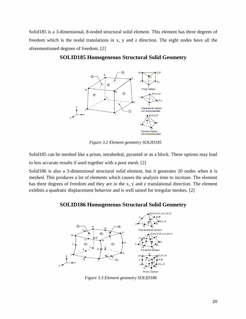
3.2.1 Element type
Ansys has a wide element library to choose element types from. Depending on the material and
the behavior of the structure it simulates, the elements needs to be chosen carefully. When the
mesh is generated, elements generate different amount of nodes depending on the element type
used. Choosing one that produces a small amount of nodes can affect the accuracy of the results,
while selecting an element that produces many nodes may be expensive in CPU-time. Also element
types that produces a high amount of nodes may cause memory issues due to the amount of
equations that needs to be calculated by the program. SOLID185, SOLID186 and SOLID187 are
often used when modeling complex geometries, and it`s a good choice when analyzing a
connection.
20
Solid185 is a 3-dimensional, 8-noded structural solid element. This element has three degrees of
freedom which is the nodal translations in x, y and z direction. The eight nodes have all the
aforementioned degrees of freedom. [2]
SOLID185 Homogeneous Structural Solid Geometry
Figure 3.2 Element geometry SOLID185
Solid185 can be meshed like a prism, tetrahedral, pyramid or as a block. These options may lead
to less accurate results if used together with a poor mesh. [2]
Solid186 is also a 3-dimensional structural solid element, but it generates 20 nodes when it is
meshed. This produces a lot of elements which causes the analysis time to increase. The element
has three degrees of freedom and they are in the x, y and z translational direction. The element
exhibits a quadratic displacement behavior and is well suited for irregular meshes. [2]
SOLID186 Homogeneous Structural Solid Geometry
Figure 3.3 Element geometry SOLID186

21
As seen in figure 3.3 the element can form the same geometries as solid185, but here the element
generates midside nodes which then again creates more elements. In solid185 the prism and
pyramid option is not recommended whereas in solid186 no recommendation is mentioned, or
preferred.
Solid 187 is 10 node, 3-dimensional solid structural element. This element has a quadratic
displacement behavior and is well suited for irregular meshes as SOLID186. This element has
three degrees of freedom in the translational x, y and z-direction. [2]
SOLID187-3-D 10-Node Tetrahedral Structural Solid
Figure 3.4 Element geometry SOLID187
3.2.2 Contact
In many FE software a determination of a connection between structural elements such as, rigid,
semi-rigid, or pinned are often predefined. If however a specific detailed connection is to be
analyzed there are multiple parameters that needs to be taken into account. When modeling contact
between two connected members the problem becomes highly nonlinear, and the need for
significant computer resources to analyze and solve the problem are crucial. It is important to be
very accurate when generating the numerical model, and really understand the physics of the
problem. When dealing with contact problems there a two general classes to choose from. This is
flexible to flexible, or rigid to flexible contact

22
In rigid to flexible contact problems one of the contacting surfaces is to be considered as having
much higher stiffness than the deformable body it contacts. A general rule is that whenever a hard
material makes contact with a soft material, the contact problem is regarded as a rigid to flexible
contact problem. Flexible to flexible contact problems occurs when two materials with similar
stiffness come into contact. This is the more common type of the two mentioned. [2]
3.2.2.1 Contact elements
Ansys has multiple element types which can be used for contact problems. Also here there are
some available only for 2-dimensional analyses while others are for 3-dimensional analyses.
Specifically two contact elements are of interest, namely CONTA173 and CONTA174.
CONTA173 is a 3-dimensional, 4 node surface to surface contact element. It is used between 3-
dimensional target surfaces and deformable surfaces which is defined by the CONTA173. This
element can be used both in pairs-based and general contact definitions. For each definitions
TARGET 170 can be used as the target surface or it can be defined by the CONTA173 itself.
CONTA173 has no midside nodes and therefore it needs to be located on a surface who does not
produce midside nodes. [3]
CONTA173 Geometry
Figure 3.5 CONTA173
CONTA174 is 3-dimensional, 8 noded surface to surface contact element. This element is used to
represent sliding and contact between a 3-dimensional target and a contact surface. CONTA174
can be used for both general, and pair-based contact. The main difference between CONTA173

23
and CONTA174 is that the latter has midside nodes. Meshing an element with midside node
produces more elements within the structure, the more elements the software produces the more
accurate the result become. However if an element with midside nodes are used and divided into
many elements by creating a very finite mesh, the analyses of the problem can be very tricky and
time consuming. CONTA174 can be used with solid elements weather it produces midside nodes,
or not. However if a contact element with midside nodes is used on an element type that has no
midside nodes the software will produce warnings and this may have an effect in the accuracy of
the finite element model. [3]
CONTA174 Geometry
Figure 3.6 CONTA174
3.2.2.2 Target elements
As mentioned earlier every contact analysis needs both a contact and a target surface. For use in
static analyses two types of target element are available, TARGET169 and TARGET170.
TARGET169 is as a 2-dimensional target surface which is combined either with CONTA171, or
CONTA172. The contact surface overlays the deformable body, while the target surface is the
surface the deformable body has as a target. [3]

24
TARGET169 Geometry
Figure 3.7 Functionality of the target elements
TARGET170 represent a 3-dimensional target surface which can be combined with contact
elements CONTA173 or CONTA174. As for TARGET169 the contact elements used with
TARGET170 overlays the deformable body, whilst the target elements are the target for the
deformable body. The main difference between the two target elements is that TARGET169 is a
2-dimensional element while TARGET170 is a 3-dimensional element. [3]
TARGET170 Geometry
Figure 3.8 Principals of the target elements

25
3.2.2.3 Symmetric and asymmetric pairs
Asymmetric pair
When modelling an asymmetric pair, one of the surfaces is defined as a target and the other as
contact. This is also known as a one-pass contact. To decide which is contact and which is target
a general advice is that if one of the bodies moves towards the other, the moving body is the contact
surface and the other is the target surface. However it is not always clear which is the moving body
and which is the target body, sometimes they both move and sometimes some parts of the body
move while the rest of the body stands still. Therefore a set of guidelines is provided by Ansys to
ease the choice. These guidelines consist of the following. [2]
- If a convex surface makes contact with a concave surface, the latter should be the target
surface
- If one of the surfaces has a finer mesh than the other, the surface with the coarser mesh
should be considered as the target
- If one of the surfaces is stiffer than the other, the less stiffer surface should be considered
as a target
- If one of the surfaces are markedly larger than the other surface, the larger surface should
be considered as the target surface
- If a higher order elements underlie one of the surfaces, and a low-order element underlie
the other surface the low-order elements should be considered as the target surface
If there still is some confusion regarding the contact and target surface, the more safety solution is
to use symmetrical contact pairs.
Symmetric pair
When modeling symmetric contact pairs, Ansys assigns both a contact and a target surface at both
bodies. This means that for every contact assembly, Ansys generates two set of contact pairs. This
way Ansys automatically recognizes the contact and target surfaces even if some of the surfaces
behaves different than the rest. Even though this type of contact is less efficient than the

26
asymmetrical contact, many analysis will need this to reduce the problem with penetration in the
model due to wrong choice of contact and target surfaces when using asymmetric contact pairs.
[2]
Figure 3.9 Schematic representation of symmetric and asymmetric contact
3.2.2.4 Contact analysis type
There are three different analyses types used when dealing with contact problems. These are: [2]
- Node to node contact
- General definition
- Pair-based definition
Node to node contact elements are used when the location of the contacts are known before
modeling the structure. Typical for this type of contact problem is when there is small-sliding
between the different contact surfaces.
The general and pair-based definition are suitable for solving both large and small sliding between
the contacting surfaces. In general it is recommended if possible, to use either of these. When
defining one of these two the following needs to be specified: [2]
- The definition of the surface for the contacting bodies
- The interaction and contact pairing for the surfaces that are in contact
- The behavior of the interface of the contacts

27
- The contact Properties
- Contact formularens
When using the general contact definition, general contact surfaces are defined. One of the contact
elements (CONTA171 through CONTA174) overlays the surface of the deformable body while
for the rigid bodies, TARGET 169 or TARGE170 are used. When this type of contact surface is
generated, Ansys assigns a unique section ID for these, so each surface consist of contact or target
elements with a unique section ID. When running the analysis Ansys search for contact interaction
among all the assigned surfaces.
In the pair-based definition an interaction is defined between target surfaces and contact surfaces.
Ansys assigns the same real constant number to the contact and target surface that are supposed to
interact with each other. When the analysis is running it searches for contact interaction by using
these real constants. [2]
3.2.2.5 Contact method
Surface to surface contact elements
This type of contact is available both when having rigid to flexible, and flexible to flexible contact
problems. In this contact type, target and contact surfaces are defined to make a contact pair.
TARGET169, CONTA171, CONTA172 are used in 2-dimensional problems, while TARGET170
with CONTA173 or CONTA174 are used in 3-dimensional problems. [2]
Node to surface contact
This type of connection uses CONTA175 elements to model either flexible to flexible, or rigid to
flexible contact pairs between a given set of nodes and a surface. CONTA175 can be applied both
for 2-dimensional and 3-dimensional problems, but does not support 3-dimensional contact
surfaces with midside nodes. [2]
3.2.3 Contact properties

28
Managing contact pairs is a challenging procedure which requires accurate modeling with the
correct parameters in order to achieve convergence. In the following, the most important
parameters will be presented.
3.2.3.1. Contact surface behavior
There are several contact surface behavior types to choose between. Some support sliding along
the surfaces, while others bond the surfaces together. The different types are as follows: [2]
- Standard contact
- Rough contact
- Bonded
- Bonded initially
- Bonded always
- No separation
- No separation always
The standard contact is a unilateral contact. This means that the normal pressure equals to zero if
separation between the contact and target surfaces occurs. When using rough contact surfaces, no
sliding will occur. Here the contact has an infinite coefficient of friction. The option of using
bonded contact results in having the contact and the target surfaces bonded in all directions
throughout the analysis from when the first contact between the surfaces occurs. When choosing
bonded always the contact detection points which are initially inside the pinball region, or that
once contact is established it always attaches to the target surface parallel to the normal direction
to the contact surface. Here the contact is fully bonded. Choosing bonded initially, the contact
detection points that initially are closed remains attached to the target surface while the contact
detection points that initially are open remains this way throughout the analysis. If the option of
no separation are used, the contact and target surface are tied throughout the analysis once contact
are established. Sliding is however possible. The last option is to have no separation always, here
the contact detection points that either are inside the pinball region or that once contact is
established it always attaches to the target surface parallel to the normal direction of the contact
surface. Here sliding is also possible. [2]
29
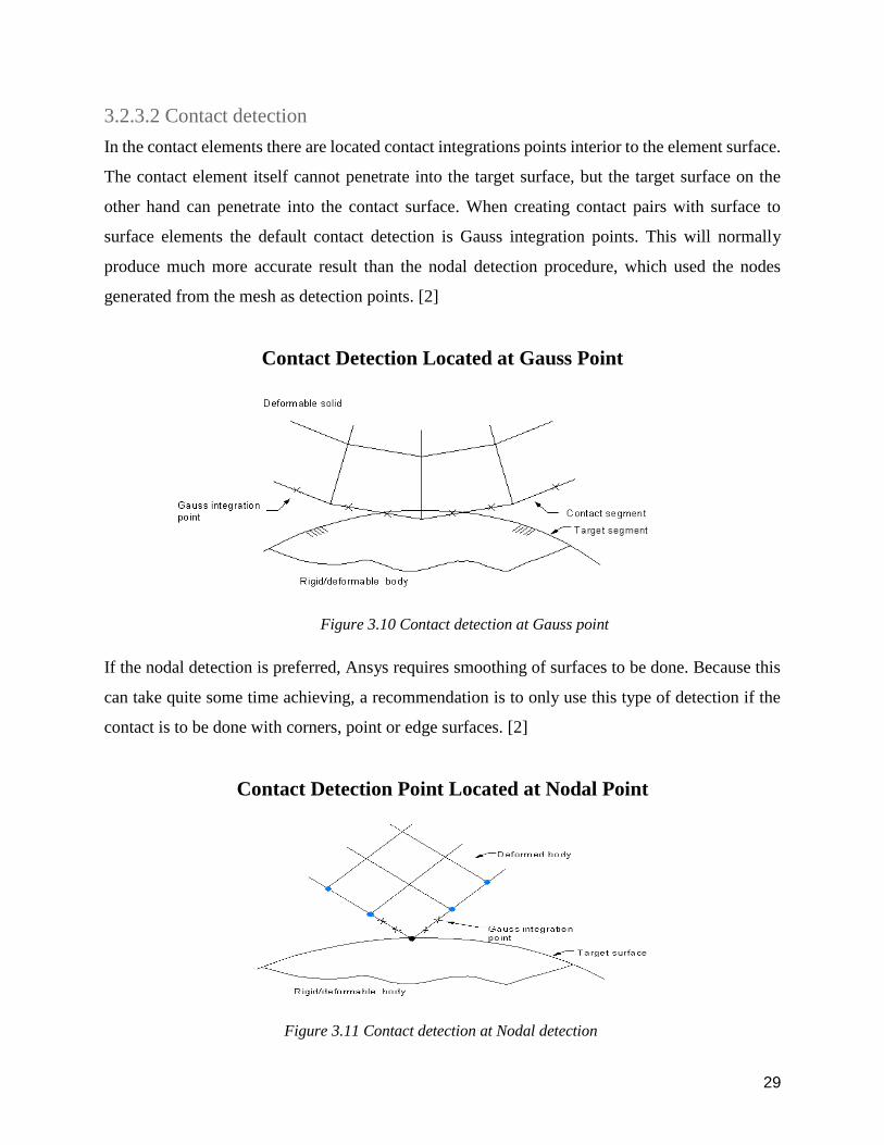
3.2.3.2 Contact detection
In the contact elements there are located contact integrations points interior to the element surface.
The contact element itself cannot penetrate into the target surface, but the target surface on the
other hand can penetrate into the contact surface. When creating contact pairs with surface to
surface elements the default contact detection is Gauss integration points. This will normally
produce much more accurate result than the nodal detection procedure, which used the nodes
generated from the mesh as detection points. [2]
Contact Detection Located at Gauss Point
Figure 3.10 Contact detection at Gauss point
If the nodal detection is preferred, Ansys requires smoothing of surfaces to be done. Because this
can take quite some time achieving, a recommendation is to only use this type of detection if the
contact is to be done with corners, point or edge surfaces. [2]
Contact Detection Point Located at Nodal Point
Figure 3.11 Contact detection at Nodal detection

30
3.2.3.3 Normal penalty stiffness
If the contact algorithm are either the Augmented Lagrange method or the penalty method, both
normal and tangential contact stiffness are required. Slip can occur in the sticking contact between
two surfaces depending on the tangential stiffness, and the amount of penetration by contact pairs
can be adjusted with higher or lower normal contact stiffness. But there is a paradox here, because
defining a high stiffness both for the tangential and the normal contact stiffness in order to
minimize the slip and penetration, can result in a troubling global stiffness matrix and can create
difficulties when the analysis tries to converge towards a solution. On the other hand using lower
values for these stiffnesses can cause some penetration and slip, and may give inaccurate results.
So the obvious method is to have high enough stiffness so that the slip and penetration is acceptably
small, but still maintain a low enough stiffness so that convergence problems does not occur. As
default a factor of 1.0 is used as a normal contact stiffness, but it can vary from 0.1-10 depending
on the contact problem. The default tangential stiffness is the same as for the normal contact
stiffness. [2]
3.2.3.4 Penetration tolerance
This feature is for use in the Augmented Lagrange method and the Lagrange multiplier method.
This factor must be lower than 1. The default value is 0.1 and this is a tolerance factor that is
applied parallel to the surface normal. The penetration factor is used to determine if the penetration
compatibility is satisfied. In order for the contact compatibility to be acceptable it is measured with
the allowable penetration which is defined by the penetration factor times the depth of the
underlying elements. So even if the software manages to achieve the convergence criteria for all
the forces and displacements, but the tolerance is beyond what is acceptable the analyses considers
this as an unconverged solution. So it is very important for this factor to be correctly adjusted. [2]
3.2.3.5 Pinball region
When the integration points on the contact surfaces is in a near-field contact, this means that there
is a small distance between these points and the corresponding target surface. This distance is

31
called the pinball region. When modeling in 2-dimensions, this region is a circle while modeling
in 3-dimension this region is a sphere and they both are centered around the Gauss integration
points. When Ansys analyses the structure and is searching for contact, the computational time
depends on the size of the pinball region. For most contact problems the default value given by
Ansys is almost always sufficient. [2]
3.2.3.6 Coulomb’s friction
In Coulomb's friction model, before two surfaces starts to slide relative to each other the two
contact surfaces can maintain some shear stresses in between them. When a contact is in this state
this is referred to as a sticking contact. Another state of contact is when a contact is sliding.
Coulomb's friction model defines a shear stress at which sliding begins as a fracture of the contact
pressure on the surface. At the point when the shear stress is exceeded the phenomena of sliding
occurs. [2]
3.2.4 Contact Algorithm
There are multiple algorithm alternatives to choose from when analyzing a contact problem. Below
is an explanation of the different types and how they work.
3.2.4.1 The penalty method
In order for the contact to be established, the penalty method uses a spring stiffness to form the
relationship between the contacting surfaces. This is also referred to as a contact stiffness. This
method can optionally use the following parameters in its algorithm: [2]
- Normal penalty stress
- Tangent contact stiffness factor
- Allowable penetration
- Maximum sliding
3.2.4.2 The Augmented Lagrange method

32
This is the default method and is actually a series of iterative Penalty methods. In order for the
penetration to be lower than the allowable tolerance, frictional stresses and pressure are augmented
during equilibrium iterations. [2]
3.2.4.3 The pure Lagrange multiplier method
When a contact pair is closed, this method enforces zero penetration between the surfaces, and
when sticking contact occurs the slip is also set to zero. This method does not use the normal
penalty stiffness or the tangent contact stiffness factor during its analysis. The two following
factors are implemented instead:
- Allowable penetration
- Maximum allowable tensile contact
The pure Lagrange multiplier method adds a contact traction as an additional degree of freedom
and during the analysis it uses additional iterations to stabilize the contact conditions. [2]
3.2.4.4 Multipoint constraint algorithm
This method is best suited in connections where the contact type is either defined as bonded, or as
a no separation contact.
An alternative algorithm is the combination of the Lagrange multiplier applied on the contact
normal, and the Penalty method applied on the frictional plane. From this we get zero penetration
combined with a small amount of slip for the sticking contact condition. For this method the
following parameters needs to be specified. [2]
- Allowable penetration
- Tangent contact stiffness factor
- Maximum slip
3.3 Equation solver

33
When the modeling is done and the different parameters is chosen, the selection of the solver for
the analysis can be chosen. Ansys has several methods for solving complex structural problems
and the available solvers in this program are: Sparse direct solution, The Jacobi conjugate gradient
solution, the incomplete Cholesky conjugate gradient solution, and the Preconditioned conjugated
gradient solution. Some of these use a direct elimination process, while others uses an iterative
procedure. [4]
The direct elimination method is a Gaussian process which solves the vector variable {u} in the
following equations: [4]
[K ] {U} = {F} (3.1)
Where
[K] is the global stiffness matrix
{U} is the global vector of unknown displacement
{F} is the applied global load vector
When using direct elimination a factorization of the global stiffness matrix is done and it ends up
as two triangular matrices, one upper and one lower.
[K ] = [L] [u ] (3.2)
Where:
[L] = the lower triangular matrix
[u]= the upper triangular matrix
By inserting equation 3.2 into equation 3.1, the following is obtained
[L][U]{u}={F} (3.3)
By using the following substitution:

34
{w}=[U]{u} (3.4)
We can use the forward pass operation by first solving the matrix system for {w},and then obtain
the global vector of nodal displacement {u} by the following :
[L] {w}={F} (3.5)
Then finally by using the back pass operation on a triangular system matrix we can compute the
global nodal solution vector {u} with the following
[U] {u}={w} (3.6)
The iterative method on the other hand initializes a DOF guess of the solution vector and by using
the global stiffness matrix this solver finds the real DOF solutions by iterating to convergence. In
the following the different types of solvers will be presented. [4]
3.3.1 The sparse direct solver
This solver uses the direct elimination of equations and requires a factorization of a linear system
of equations into triangular matrix of a lower order. When this matrix is at place the method
substitutes back and forward using this triangular system. If there are problems producing
solutions, then the sparse direct solver is brilliant even if the initial equations are poorly
conditioned [1].
3.3.2 The Preconditioned conjugate gradient (PCG)
This type of solver starts the solution step with element matrix formulations. Starting with a guess
of all the DOF solutions, the solver sets up the global stiffness matrix and by iteration calculates
the real DOF solution by convergence. As a proprietary preconditioner the solver uses material
property and element dependent variables. The PCG is about 4 to 10 times faster in calculating the
solutions than the Jacobi solver, but the solver requires about twice as much memory as the Jacobi

35
solver. This solver performs well on static analyses but are very limited in nonlinear analyses. This
solver also performs well in contact analysis as long as rigid body motion does not occur because
of the non-linearity [1].
3.3.3 The Jacobi conjugate gradient solver
As for the case of the PCG, this solver starts with element matrix formulations. Then it assembles
the global stiffness matrix and by guessing on the DOF solutions to solve the real DOF solution
by iteration, it converges. As a precondition this solver uses the diagonal of the stiffness matrix.
However this method is usually used for thermal analysis [1].
3.3.4 The Incomplete Cholesky Conjugate Gradient Solver
This solver has the same principals as the Jacobi solver except that this solver is more robust to
solve matrices which are poorly conditioned, but the solution needs twice the memory than the
Jacobi solver. This analysis is well suited for thermal and electrical analysis but is available also
for static, transient or harmonic analyses [1].
3.4 Newton-Raphson procedure
When the solution is nonlinear a new set of equations is to be used. For this purpose Ansys uses
the Newton Raphson method. The procedure of the calculation consist of a set of simultaneous
equations [4]:
[K ] {U} = {Fa} (3.7)
Where :
[K ] is the coefficient matrix

36
{U} is the vector of unknown degrees of freedom
{Fa} is the applied loads
Whenever the coefficient matrix itself is a function of the unknown DOF`s, then the equation
above becomes nonlinear. To solve this Ansys uses the Newton-Raphson method with the
following equations [4]:
[KiT] {∆Ui} = {Fa} - {Fi
nr} (3.8)
{∆Ui+1} = {Ui} - {∆Ui} (3.9)
Where
[KiT] is the Jacobian matrix
{Finr} is the vector of restoring loads corresponding to the element internal loads.
At least more than one iteration is needed to obtain a solution. First {U0} has to be assumed,
normally this value is the converged solution from the previous time step. However if it is the first
time step this value is set = {0}. Then the updated tangent matrix [KiT] and the restoring load {Fi
nr}
is computed due to the configuration of {Ui}. In the next step {∆Ui} is calculated
and now the two parameters of {∆Ui} and {Ui} can be added together to obtain {Ui+1}
which is the next approximation. This is repeated until convergence is achieved [4].
Figure 3.12 First iteration in Newton Raphson procedure

37
The solution obtained at the end of the iterations correspond to the load level {Fa}. None of the
intermediate solution will be in equilibrium except for the last final converged solution. The
principal for calculating the next iteration after the first one is shown below [4]:
Figure 3.13 second iteration in Newton-Raphson procedure
3.5 Pretension
The beam and the column in this thesis are connected together with top and seat angle and bolts.
When bolts are mounted at the construction site the bolts are tied to hold construction elements
together before loading the structure. This also has to be simulated in Ansys, so two load steps has
to be created. One where the bolt gets tightened, and a second load case where the external loads
are applied. In the first case a pretension is defined in the bolts. This clamps the bolts together
towards the center of the bolts. Ansys does this by generating a pretension element within the bolt.
For this purpose Ansys used the PRETS179 element [4].
PRETS 179 can be used only when the model is meshed and it can be used to define both 2 and 3
dimensional pretension sections. This element has only one degree of freedom and that is in the
translational x-direction, however if a pretension is needed in the y-direction Ansys transforms the
geometry of the problem internally, so that even though the pretension-force arrow is always
aligned with the x-axis the force works in the direction specified. After a pretension section is

38
defined a bolt load can be applied and 3 alternatives as to how the section behaves are given, these
are [4]:
Lock = this value is the default, and connects the cutting plane on the pretension section.
Slid = this value disconnects the cutting plan on the pretension section
Tiny = this value applies a pretension load of 0.1 % of a specified load.
PRETS179 Geometry
Figure 3.14 Tension after adjustments
Ansys also gives the opportunity to lock the pretension load after it has been applied, so that the
bolts only gets tightened during the first load step while in the next load step only the external
loads are applied. If a lock is not made on the pretension, then for every load step a new pretension
will be defined. This causes the bolts to clamp more than intended.
3.6 MESH
After a geometry is created, meshing of it is needed in order to run the analysis. The mesh of a
model is crucial for the results predicted by the program. In meshing the model is divided into
several elements and by using the finite element method it solves the mathematical equation
needed to predict the solution for every element. When all element equations are solved the
program adds up the solutions together to predict the behavior of the total structure. The finer the
mesh is the more accurate the results become. The problem however with using a very fine mesh

39
is that the solution can become very time-consuming and the need for computers with a lot of free
space is also needed. This is because a set of equations is needed for each element, and by using a
fine mesh more elements are created and thus more equations is needed to obtain the solution. The
optimal way to mesh is by using engineering sense to know where the stresses of interest are, this
way a coarser mesh can be used in areas that are not of interest while a finer mesh can be created
in the more interesting fields of the model.
Figure 3.15 fine vs coarse mesh
In Ansys two main types of mesh can be used, this is free or mapped mesh. A free mesh has no
restrictions in how the elements are shaped, and has no specific pattern assign to it. A mapped
mesh however is restricted to the shape of the elements as well as the the pattern used to mesh it.
In figure 3.16 the elements have a mapped mesh, and as seen the mesh has very obvious rows of
elements. If this is preferred then when constructing the geometry it has to consist of fairly regular
forms and shapes. For complex geometries the best option would be to use free mesh. This may
visually not be the best choice, but it is a necessity in some cases.
Figure 3.16 free vs mapped mesh

40
4 Numerical Modelling
4.1 Scripting in Ansys
In order to construct the model with its respective parameters, scripts has been written. The
advantage of using a script based model is that any parameter can easily be changed unlike when
using the graphical alternative. In the last case, the user needs to save every step during modeling
formation. Since Ansys is a complex software, errors may occur for instance due to insufficient
memory space of the computer used in the process. The possibility of losing the model and the
need to start over would be time consuming and very frustrating.
The final scripts are presented in the Annex of this thesis. It is easy for the reader to copy and paste
this script into the text editor in Ansys, in order to view our model and analyze the results. This is
very convenient for structural engineers and for future research within the same field.
4.2 Connection description
In order to have reliable results, a validation of the FE-model needs to be performed. Normally
experimental tests are done before modeling and the test results are used for the validation of the
numerical model. The results from both cases are compared. If the results are within acceptable
limits, the model can be safely used for further optimization and analysis of the construction.
Because of the lack of resources at the university and the short time at hand, experimental testing
could not be done for our model. So by searching the international literature, a paper published by
a research team from Imperial College London related to testing of hybrid connections was
selected for validation of our numerical model [14]. This paper presents hybrid connections
between a tubular steel column and a glulam beam that are connected to each other in different
ways. An experimental test as well as a numerical model in Abaqus of the connections are
presented and the results are published. Because one of these connections was of interest for this
thesis and for the validation of the results of the numerical analysis, the base numerical model used
throughout the thesis is constructed according to an experimental specimen and the testing
procedure described in the paper. Of course the effect on the connection’s behavior as a result of

41
changing several parameters into the base model, in order to find an optimum solution, is the
innovative part and the main contribution of the presented work.
The geometry of the connection under study (base model) is as follows:
- The glulam beam has a height of 405 mm, and width of 140 mm
- The steel column has the dimension 150 x 10 mm, with a steel grade of S355
- The top and seat angle has the dimension 150x200 mm, with a steel grade of S275
- The vertical bolts that goes through the glulam beam, are M12 with a steel grade 10.9
- The horizontal bolts that is connected to the column, are M16 with a steel grade 10.9
Figure 4.1 Abaqus vs. Ansys Model

42
Because timber is an orthotropic material its parameters are different in the various directions.
Table1
Mechanical Properties for glulam GL28h
The geometry for the top and seat angle are seen in figure 4.2. [14]
Figure 4.2 top and seat angle
Table 2
Distances between the bolt holes and the edges
4.3 Assumptions and simplifications
Some simplifications had to be done because of the complexity of the experiment and the limit of
the time available. Contact problems are highly nonlinear and there are many parameters to choose
between. The following simplifications has been made when modelling and analyzing the
connection
- The blind bolts that are mounted into the tubular column and then expanded beyond the
thickness of the wall of the column, are simulated with a standard bolt with a nut. The
behavior of the blind bolts used in the experiment are not well documented and modelling
this would be highly time-consuming. This may cause some difference when validating the
model

43
- Because of the computational time and the disk-place needed to converge towards a
solution, only a quarter of the length of the beam is modelled.
- The verification is done in the elastic zone of the materials, so when plotting the moment-
rotation curve a comparison is done within this area
- When plotting the moment-rotation curve we used the empirical formulas proposed by
Sang-Sup Lee and Tae-Sup Moon [15], to calculate the generated elastic moment in the
connection by using the rotation extracted from Ansys. The proposed formulas are
presented below
(4.1)
Where db = is the depth of the beam
Δe = is the elastic deformation
Ø = is the rotation of the connection
le = is the effective length of the angle
And the reaction force Pe is given by the following expression
(4.2)
Where the gauge distances g1, and g2 of the angle are given below
Figure 4.3 Behavior of angle

44
Sang sup-lee argues that it is the top angle only that resist the bending moment. This is also
assumed for our case studies. In the formulas presented above the effective length of the angle are
made as a simplification. Sang-Sup Lee assumed this length to be the diameter of the nut of the
bolt connected to the column, multiplied with the number of bolts connected to the column.
Because of lack of information about the blind bolts used in the experiment, the diameter of the
nuts inside the column in the FE-analyses is assumed to cover the whole width of the tubular
column. This gives us a more accurate value for the moment obtained in the connection compared
to the experiment related to the rotation that occurs from any given load.
4.4 Contact parameters used in ANSYS APDL
The parameters described in section three will here be presented with the argued reason for its use.
4.4.1 Element type
Between SOLID185, 186 and 187, the last one is preferred for this model. SOLID185 does not
have midside nodes, and thus creating a less accurate geometry of the meshed model. SOLID186
has midside nodes, but the element creates a total of 20 nodes within one element. This causes
many iterations and can become very expensive in computational time. SOLID187 however
produces only 10 nodes and the element has midside nodes. This creates fairly accurate result
because of the midside nodes, without using much CPU time. For this reason it is the most suitable
element for our model [3]
4.4.2 Contact and target elements
The surface to surface elements have several advantages over the node to node element CONTA
175. The surface elements provides better contact results for typical engineering purposes They
have no restriction on the shape of the target surfaces, and they support both high and low order
elements on both contact and target surfaces. This means that they are well suited both for elements
that have midside nodes, or the ones with corner nodes only.

45
Because of the flexibility of the surface to surface elements and the provision of result better than
that from node to node elements, we use surface to surface elements in our modelling. Between
CONTA173 and CONTA174 the latter is the preferred one because of the special geometry of the
model. When using the element with midside nodes we create a more accurate meshed model. This
is because the geometry has more nodes to build up around and thus making it more accurate than
an element without midside nodes. For this reason we use CONTA174 in our model.
The corresponding target element used in the model are TARGET 170. The main difference
between TARGET 169 and the one used in the model, is that TARGET 169 are used on 2-
dimensional models. We obviously have a 3-dimensional contact problem and for this reason
TARGET 170 is the correct choice [3].
4.4.3 Contact analysis type
In general it is recommended to use either pair-based or general contact. Between these two,
general contact is a less efficient and less robust solution compared to the pair-based. The general
contact decides automatically definitions with limited user interventions. Also general contact is
often used when the choice of contact and target surfaces are unclear or unknown. Because we
want an efficient and a robust solution we use the pair-based contact with the option of using
symmetrical pair [2].
4.4.4 Contact surface behavior
The standard contact surface is used in all contact pairs except between the bolt heads and the
angles. Here the surface behavior are set to be bonded always. This is because after pretension is
set, the bolt heads are supposed to have contact with the angles at all times [2].
4.4.5 Friction
Choosing the correct friction coefficient are crucial to the results. Too much friction can cause no
movement of the elements at all, while if it is too small the elements can move quite a lot compared
to each other. So in order for our model to be validated against the experiment the coefficient of
friction is set 0.7 as in the numerical model done in the paper [14].
46
4.4.4 Contact algorithm
The contact algorithm has to be chosen carefully so that it matches the problem at hand. Even
though the Augmented Lagrange method in some analyses may require more iterations than the
penalty method, it usually leads to better conditioning and it is less sensitive to the magnitude of
the contact stiffness than that of the penalty method.
The pure Lagrange multiplier requires additional iterations to make the contact condition stabile.
This often results in an increase in computational time and is therefore less effective than the
Augmented Lagrange method. For some of the regular analyses it is recommended to use the
Augmented Lagrange method instead of the Lagrange multiplier method. The MPC algorithm is
recommended when using bonded or no separation contact behavior. Because we in the model are
using both bonded, and standard contact, we use the Augmented Lagrange method for all cases
except for the bonded ones. Here we use the MPC algorithm taking into consideration the
reasoning above [2].
4.4.5 Equation solvers
Ansys has defined limits for the use of different equations solvers. For models with a maximum
DOF of 500 000, the sparse direct solver is recommended. From 500 000 and beyond different
types are relevant. In our model we are far away from 500 000 DOF, so the recommended solver
for our analyses are the direct sparse solve. In addition to this the sparse direct solver is brilliant
when convergence problems occurs, or when the equations are poorly conditioned. For these
reasons the sparse direct solver is used in our analyses [1].
4.5 External loading, pretension, and boundary conditions
By trying with different displacement set on the end of the beam it became clear that for
displacements larger than approximately 7 mm the materials enters into plastic behavior. Therefore
the connections was analyzed for loads up until a displacement of 7 mm was obtained. The total
displacement are not set at once, but it is divided into seven load steps so as to not cause failure.
In each load step a deflection of 1 mm is therefore applied. As in real life the bolts has to be

47
tightened before the external load is applied. This is done by using two load steps as explained in
chapter 3.5. The applied torque to the bolt connected to the column is 190 Nm and the applied
torque to the bolts connected to the beam is 100 Nm [14]. The conversion from torque to pretension
is given in the chapter 2.4 and are as follows
Ma = k*d*Fp (4.3)
The coefficient K varies between 0.15-0.3 depending on the threading of the bolt and the surface
friction. Because of lack of information about these parameters a factor of 0.3 is used in all cases
[17].
Table 3
Pretension calculated from given torque
Diameter of the bolt Pretension
M12 Vertical 27KN
M16 Vertical 20 KN
M20 Vertical 16 KN
M16 Horizontal 39KN
Our model is constrained from moving out of plane, and the column is fixed near to the top and
near to the bottom so as not to move in any directions.
Figure 4.4 constraining the column

48
4.6 Singularities
When modelling in FE-software one of the most important parameters to observe is the stresses
that occurs, specifically von Mises stress. This is the average stress that occurs in the model, and
it has to be analyzed with accordance to the yielding of the material. What is important to know is
that not all the stresses calculated from the FE- software are real stresses that needs to be taken
into account. These stresses are referred to as singularities. A stress singularity is a point in the
mesh model where the stress does not converge toward a specific value. If the mesh is refined in
this point the stresses only increases and theoretically the stress singularity is infinite.
A typical place for the singularities is at the point which the load is applied, or at sharp re-entrant
corners. Even though the values in these points are high this does not mean that the values for the
entire model are incorrect, but the singularity will cause the nearby elements to have some higher
value than in reality. So when analyzing the results in this thesis the values with some distance
from the singularities are used [5].
4.7 Model validations
The FE model described in this thesis is validated with the experimental test done in Imperial
College. We have been focusing our model on elastic behavior because of the complexity of
plasticity in Ansys. One of the most reliable way to verify a numerical model with an experiment
is by plotting the moment-rotation curve. For each load step up until the seventh, rotation in the
beam is calculated from the given displacement from Ansys. Then the obtained moment is
calculated with the formula proposed by Sang sup-Lee. As we can see from figure 4.5 a reasonable
prediction of rotational stiffness can be achieved by the numerical model developed in Ansys.
There are some minor differences but these are within the limit of what is acceptable.

49
Figure 4.5 Verification of the model
Because the rotational stiffness are fairly accurate compared to the experiment, the numerical
model made in Ansys is assumed to produce result which are both solid and reliable. Hence the
optimization of the connection can be executed.
For the comparing of von Mises stress the values tested in the laboratory of the angle bracket will
be used. These values showed a yield strength from tests on 14 angle brackets and their values are
higher than the yield strength of 275 n/mm2 defined from the factory. Therefore our models will
be compared to, and analyzed with the values tested in the experiment [14].
Table 4
Stress values taken from experimental test
Top and Seat angle Yield stress [Mpa] Ultimate stress [Mpa]
L 200 x 150 x 15 408 514

50
4.8 Case studies
In order to for us to analyze the different parameters of the connection, 7 different case studies are
carried out. To analyze between the original connection and the optimized ones, the verification
result from the FE-software for the original connection are presented as well. The following cases
and changes has been analyzed.
Table 5
Case studies
Case nr Modifications in connection
1 This is the predicted results from the FE-software for the original connection
2 The thickness of the top and seat angle are changed from 15 to 18mm
3 The thickness of the top and seat angles are increased to 20 mm
4 The diameter of the vertical bolts are changed from 12 to 16mm
5 The diameter of the vertical bolts are changed to 20 mm
6 A reduction of 20 mm in the width of the top and seat angle are made
7 The thickness of the top and seat angle are changed to 12 mm, with a 14 mm
stiffener placed in the middle of the top angle
In all the cases the main results to be compared are the moment-rotation relationship, von Mises
stresses and the initial rotational stiffness. The methodology used to obtain these result are
described below.

51
4.8.1 Moment rotation
In all case studies a displacement of 10 mm was set on the end of the beam. Then every load step
was analyzed up until the seventh, as mentioned in chapter 4.5. For each load step the horizontal
deflection of the glulam beam was together with the height of the beam (db) used to calculate the
rotation by using the following equation
Ø = arctan (Δe/ db) (4.4)
Also when the horizontal deflection of the beam is known, the reaction force P as shown in figure
12 can be calculated. By inserting these parameters into the formula proposed by Sang Sup-Lee,
the obtained moment in the connection can be calculated, and the moment-rotation relationship
can be established
For the case study with stiffener, the formula proposed by Sang Sup-Lee to calculate the occurred
moment in the connection cannot be used without adding a coefficient. In order to find this
coefficient the following simplified method is proposed
First a model of the top angle itself is made. Then the horizontal leg is constrained in the y-direction
and the angle itself, is constrained in the z- direction. To resemble the action of the bolt, the vertical
leg is constrained at the top in x-direction as well. Then a load is applied in the same manner as
the load P as seen in figure 4.3. The deflection in the x-direction is then extracted. The next step
is to model the angle by itself with a stiffener and make the same loading and constraints. Then
the deflection in the x- direction is extracted. When the two deflections are found the calculation
of the stiffness of both angles in the x-direction are made with the following simplified equation
F = K*X (4.5)
Where
F is the applied load
K is the stiffness of the angle in X-direction
X is the deflection of the angle

52
In this manner it became clear that the changes in stiffness is quite some amount. By using equation
4.5 a ratio between the two stiffnesses is found and multiplied with the reaction force P, which
again is used to calculate the occurred moment in the stiffened connection
Figure 4.6 Deflection in the top angle with and without stiffener
4.8.2 von Mises stress
When analyzing von Mises stress, a set of coordinates is used to monitor the stresses at the same
points in the top angle. By doing this we can monitor how the same areas on the angle changes
with the different cases. Because case 1, 2 and 3 have different thicknesses of the angles, the
coordinates differ slightly, but this is taken into consideration so that the points actually are in the
same positions in every case. In case 7 where the stiffener is applied in the middle of the top angle
a comparison of the stresses with case 1 is not accurate because the difference in geometry. The
reason for this is that almost all the stresses goes through the stiffener instead of through the corner
of the angle. So the magnitude of the stresses will not be comparable
4.8.3 Initial rotational stiffness
Eurocode 3 part 1-8, provides coefficients needed to calculate the initial rotational stiffness of
connections. However for square hollow sections these are not included. For the connection in this
thesis the coefficients needs to be calculated first in order to obtain the initial rotational stiffness

53
of the whole connection. The contribution to the rotational stiffness for the top and seat angle in
total can be evaluated with the contribution from the bearing stiffness of the column face and the
axial stiffness of the bolts connected to the column. For the calculation of the bearing stiffness of
the column face, Elghazouli uses the following equation [16].
(4.6)
Where
E is Young's modulus for steel
tc is the thickness of the wall of the column
is Poisson's ratio for steel
bc is the width of the column face
To calculate the tension and compression stiffness in the horizontal leg of the top and seat angle
Elghazouli uses the following equation [16]]
(4.7)
Where
E is Young's modulus for steel
p is the width of the angles
is the thickness of the angle
is the distance from the inner bolt hole to the vertical leg of the angles
With regards to the stiffness of the bolt that connects the top angle to the column, Elghazouli have
presented curves from which the stiffness can be read for the blind bolts. For standard bolts
Elghazouli uses equation 4.8 to calculate the stiffness, but this is for the connection of the top angle
to the beam only.

54
(4.8)
Where
E is Young's modulus for steel
Ab is area of the bolt
Lb is the length of the bolt subjected to axial tension
N is the number of bolts that contributes to the stiffness
As seen in equation 4.8, the area, length, and Young's modulus for the bolts are the parameters
used to calculate the axial stiffness of the standard bolts. So even though the formula is related to
the connection between the angles and the beam, it is assumed that this also is valid for the
connection between the angle and the column as well. When the stiffness coefficients are found,
they are used in the following formula to calculate the stiffness of the top angle [14].
(4.9)
As seen in the equation the stiffness for the hollow bolts are used. This is substituted with the
stiffness of a standard bolt as explained above. To calculate the stiffness of the seat angle
however, the following formula are used [14].
(4.10)
The difference between the two stiffnesses is that there are no stiffness contribution from the bolts
in the seat angle. This is because the bolts are not subjected to tension hereto calculate the stiffness
of the total connection the following formula are used [14].
(4.11)
Where db is the depth of the glulam beam. This final equation is used to calculate the initial
rotational stiffness for the different cases. In order to further verify whether the connection is rigid,
semi-rigid or nominally pinned the criteria mentioned in section 2.3.3 will be examined.

55
5 Results
In this chapter we will present the results obtained from the case studies. Because the discussion of the
result will be done in the next chapter, only the result will be presented here.
5.1 Case 1
Table 6
Moment rotation at different load steps for case 1
Figure 5.1 The moment-rotation curve in case 1

56
Table 7
Von Mises stress for top angle at different coordinates for case 1
Figure 5.2 von Mises stress in the top angle in case 1

57
Figure 5.3 von Mises stress in the seat angle in case 1
Figure 5.4 Stress perpendicular to the glulam beam at the first load step in case 1

58
Figure 5.5 Stress perpendicular to the glulam beam at the second load step in case 1
Figure 5.6 von Mises stress in the vertical bolts in case 1
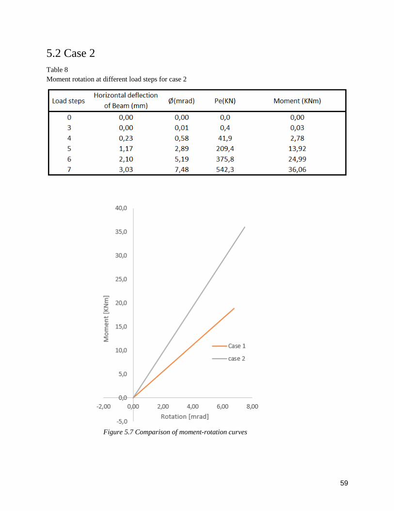
59
5.2 Case 2
Table 8
Moment rotation at different load steps for case 2
Figure 5.7 Comparison of moment-rotation curves
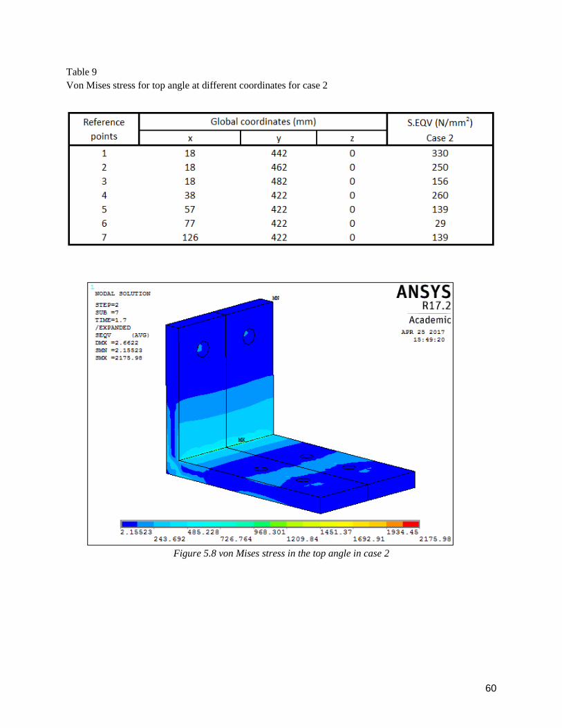
60
Table 9
Von Mises stress for top angle at different coordinates for case 2
Figure 5.8 von Mises stress in the top angle in case 2

61
Figure 5.9 von Mises stress in the seat angle in case 2
Figure 5.10 Stress perpendicular to the glulam beam at the first load step in case 2

62
Figure 5.11 Stress perpendicular to the glulam beam at the second load step in case 2
Figure 5.12 von Mises stress in the vertical bolts in case 2

63
Table 10
Von Mises comparison between case 1 and case 2
5.3 Case 3
Table 11
Moment rotation at different load steps for case 3

64
Figure 5.13 Comparison of moment-rotation curves
Table 12
Von Mises stress for top angle at different coordinates for case 3

65
Figure 5.14 von Mises stress in the top angle in case 3
Figure 5.15 von Mises stress in the seat angle in case 3

66
Figure 5.16 Stress perpendicular to the glulam beam at the first load step in case 3
Figure 5.17 Stress perpendicular to the glulam beam at the second load step in case 3

67
Figure 5.18 von Mises stress in the vertical bolts in case 3
Table 13
Von Mises comparison between case 1 and case 3

68
5.4 Case 4
Table 14
Moment rotation at different load steps for case 4
Table 15
Von Mises stress for top angle at different coordinates for case 4

69
Figure 5.19 von Mises stress in the top angle in case 4
Figure 5.20 von Mises stress in the seat angle in case 4

70
Figure 5.21 Stress perpendicular to the glulam beam at the first load step in case 4
Figure 5.22 Stress perpendicular to the glulam beam at the second load step in case 4
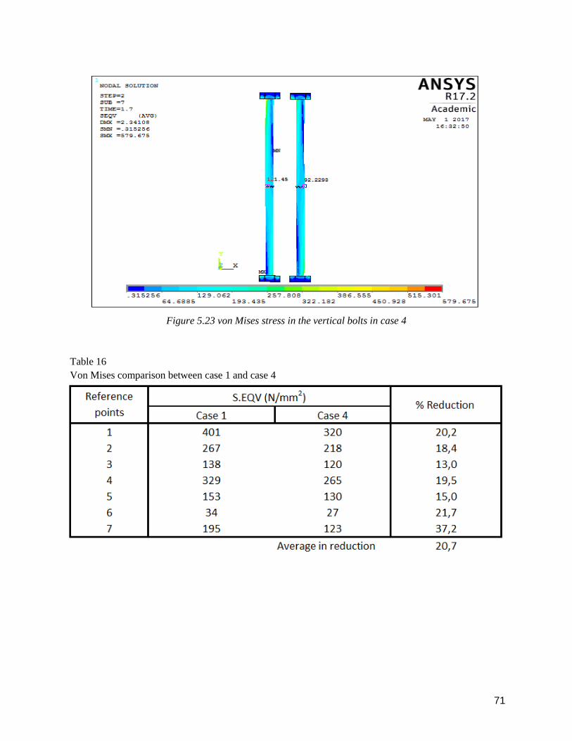
71
Figure 5.23 von Mises stress in the vertical bolts in case 4
Table 16
Von Mises comparison between case 1 and case 4

72
5.5 Case 5
Table 17
Moment rotation at different load steps for case 5
Figure 5.24 Comparison of moment-rotation curves

73
Table 18
Von Mises stress for top angle at different coordinates for case 5
Figure 5.25 von Mises stress in the top angle in case 5
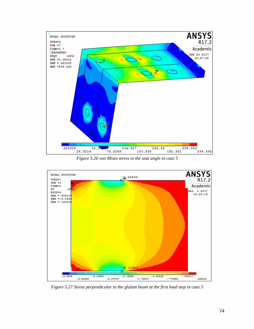
74
Figure 5.26 von Mises stress in the seat angle in case 5
Figure 5.27 Stress perpendicular to the glulam beam at the first load step in case 5

75
Figure 5.28 Stress perpendicular to the glulam beam at the second load step in case 5
Figure 5.29 von Mises stress in the vertical bolts in case 5
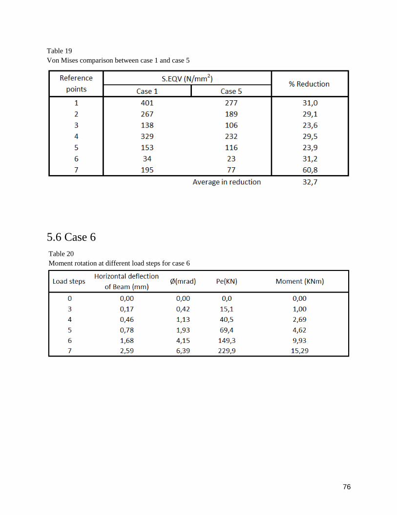
76
Table 19
Von Mises comparison between case 1 and case 5
5.6 Case 6
Table 20
Moment rotation at different load steps for case 6

77
Figure 5.30 Comparison of moment-rotation curves
Table 21
Von Mises stress for top angle at different coordinates for case 6
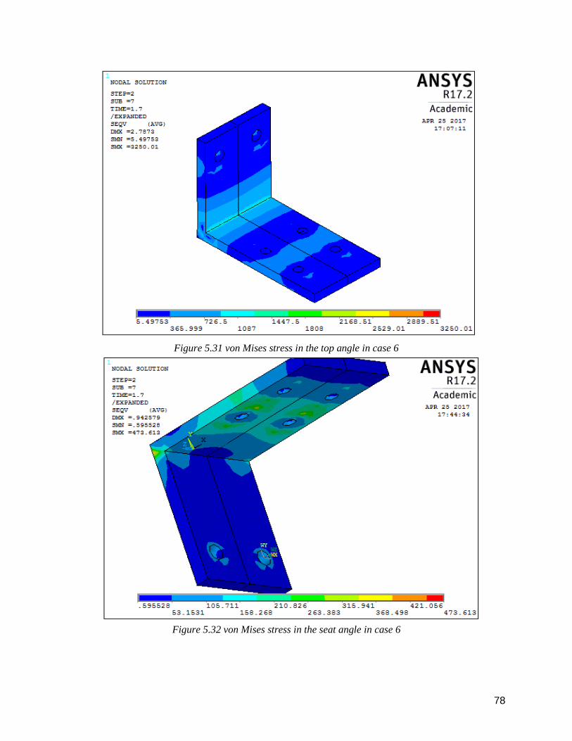
78
Figure 5.31 von Mises stress in the top angle in case 6
Figure 5.32 von Mises stress in the seat angle in case 6

79
Figure 5.33 Stress perpendicular to the glulam beam at the first load step in case 6
Figure 5.34 Stress perpendicular to the glulam beam at the second load step in case 6

80
Figure 5.35 von Mises stress in the vertical bolts in case 6
Table 22
Von Mises comparison between case 1 and case 6

81
5.7 Case 7
Table 23
Moment rotation at different load steps for case 7
Figure 5.36 Comparison of moment-rotation curves

82
Table 24
Von Mises stress for top angle at different coordinates for case 7
Figure 5.37 von Mises stress in the top angle in case 7

83
Figure 5.38 von Mises stress in the seat angle in case 7
Figure 5.39 Stress perpendicular to the glulam beam at the first load step in case 7
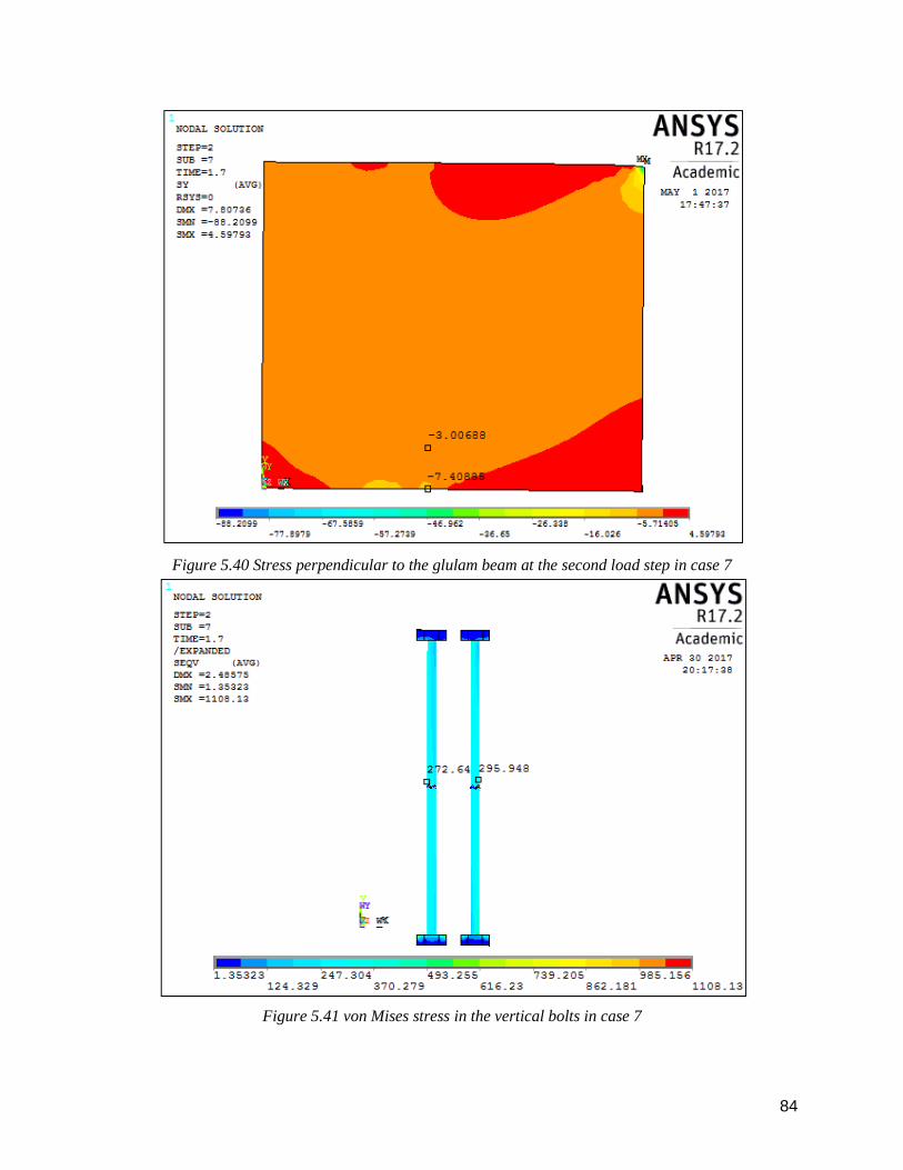
84
Figure 5.40 Stress perpendicular to the glulam beam at the second load step in case 7
Figure 5.41 von Mises stress in the vertical bolts in case 7

85
5.8 Initial stiffness of connections
Table 25
Initial stiffness of connections
Cases 4 and 5 has no change in the initial rotational stiffness. The evaluation of case 7 with stiffener is
done with a simplification. Case 7 has 53.6% higher rotational stiffness than case 1, but it has a lower
rotational stiffness than case 3. So the initial rotational stiffness for case 7 is between 5.47KNm/mrad-
5.48KNm/mrad.
86
6 Discussion
Before running the analyses of the cases some results are expected according to engineering sense. For
instance for every case involving increasing of the angle thickness, or adding stiffeners, the rotational
stiffness of the connection is expected to rise due to the increased thickness. The question is the amount of
the increase for the different cases and the effect of each parameter modification. Von Mises stresses are
expected to decrease in the top and seat angle due to the addition steel. The amount of the decrease however
needs to be investigated.
For each case the main discussion is related to the rotational stiffness of the connection and von Mises stress
in the top angle. The seat angle, the glulam beam and the bolts connected to the beam are also discussed
but not at the same extent. All case studies have been compared to case 1 which has been used as the base
case study during the analysis.
6.1 Effect of changing the angle thickness
By varying the thickness of the top and the seat angles, the rotational stiffness of the connection changes
significantly. The original connection had angles with a thickness of 15 mm and these were changed to 18
and 20 mm. As seen in figure 5.7 the moment resistance occurred in case 2 increases with 73% compared
to the original connection. In case 3, a dramatic increase of 137% in rotational stiffness occurred in the
connection as seen in figure 5.13. This indicates that by changing the thickness of the angles even with a
small amount, a huge effect on the overall rotational stiffness for the connection is obtained. As expected
the connection becomes stiffer when the thickness of the angles are increased. However the increase in the
amount of steel in the angles are 21% and 35.2% for case 2 and 3, respectively. von Mises stress in the top
angle is decreased with 12.2% in case 2 as seen in table 10 while as seen in table 13 a reduction of 15.5 %
in von Mises stress was observed in the top angle in case 3. Since the volume of the angles becomes greater,
the stresses distributed on them decreases compared to case 1. The reduction of von Mises stress between
cases 2 and 3 compared to case 1 are minimal compared to the increment of the volume of steel for the two
cases

87
6.2 Effect of changing the diameter of the bolts connected to the
beam
When changing the diameter of the bolts as in cases 4 and 5, there were no increase observed in the
rotational stiffness of the connection as seen in figure 5.24. This implies that changing the diameter of the
bolts, are insignificant in this matter.
The reduction of von Mises stress in the top angle are presented in table 16 and table 19 for cases 4 and 5,
respectively. In case 4 it is observed a reduction of 20.7 %, while in case 5 a reduction of 32.7% was
observed. The volume of bolts however increases significantly. The decrease in von Mises stress in the top
angles makes it possible for the angles to be subjected to some normal and shear stresses as well.
6.3 Effect of reducing the width of the angles
When reducing the width of the angle by 20 mm, a reduction of the rotational stiffness in the connection
by 14.15 % was observed and the volume of steel in the angles was reduced by 14.28 %. As expected the
stiffness of the connection is reduced. Von Mises stress in the top angle is increased with 11.8 % as seen in
table 22. Generally this indicates that whenever the reduction of the top and seat angle are done the
rotational stiffness decreases, while the stresses increases.
6.4 Effect of using a stiffener in the top angle
In case 7 the rotational stiffness of the connection increases with 53.6 % compared to case 1. The
comparison of von Mises stress between the two cases is not accurate, and from figure 5.38 it is seen that
some locations have values over the elastic limit. However a reduction of 10.4% in the volume of steel in
the top angle is observed in case 7.

88
6.5 Seat angles
Effect of changing the angle thickness
In the cases 1, 2 and 3 the stresses that occurs in the seat angle reduces as the thickness of the angle
increases. For cases 4 and 5 a reduction of von Mises stress was also observed. However in case
study 6 the reduction of the width of the angle leads to higher von Mises stress. This is due to the
amount of steel that the von Mises stress are distributed amongst. In case 7 at the top-end of the
stiffener in the corner, high values are observed. These are most likely singularities, but high values
are also observed in the seat angle in the middle of the angle under the bolt heads. This is because
when the horizontal leg of the seat angle bends, pressure is applied on the seat angle from the bolt
heads and causing these locally high stresses. The pretension in the first load step clamps the top
and seat angle together towards the center of the bolts. Since the top angle are much stiffer than
the seat angle, a higher deformation is done in the seat angle. This results in higher stresses in a
few locations in the seat angle than for the top angle.
6.6 Wood failure
In all cases wood failure occurs in the glulam beam. When the pretension are applied to the bolts,
the wood crushes because of compression of the top and seat angle. Then when the external load
is applied to the beam the compression increases in the lower part of the beam when it is pushed
towards the seat angle, causing even more crushing. Wood crushing in the top angle does not
increase because the beam is bent away from the angle when the external load is applied. The beam
has a capacity of only 3.6 N/mm2 perpendicular to the grain, while in the longitudinal direction it
has a capacity of 33 N/mm2. The highest stress perpendicular to the grain was observed in case 3
and is approximately 8.28 N/mm2. The high stresses however do only penetrate the beam section
by a small amount. The stress perpendicular to the grain in case 2 increases compared to case 1,
but not as extensively as for case 3. This indicates that the stresses perpendicular to the grain that
occurs in the beam becomes larger when the angles are stiffer. This is most likely because
whenever an angle is flexible, the beam deflects with the angle. On the other hand when the angle
is very stiff the beam deflects mostly alone, resulting in a higher pressure from the angle. However

89
solving the problem with wood failure is not the main goal of this thesis. A presentation of the
wood failure is only due to show what level of perpendicular stress that occurs, and the reason for
this. Solving this problem may be taken as a continuation of this thesis, if desirable.
6.7 Vertical bolts
For cases 1, 2 and 3 the changes in the von Mises stress in the bolts are negligible. In cases 4 and
5 however the pretension and the bolt diameter change. While the diameter for the bolts increases,
the pretension load decreases. Because the force is lower and distributed is on a smaller area than
the previous cases the bolts are subjected to lower von Mises stress. It is only when adding a
stiffener that a large increase of the von Mises stress are found in the bolts. When the pretension
is applied, the stiffener at the top angle resist the clamping from the bolts much more than for the
cases without stiffeners. This causes von Mises stress in the bolt to increase.
6.8 Initial rotational stiffness
For all cases the theoretical rotational stiffness are calculated. For cases 4 and 5 the initial rotational
stiffness remains unchanged while some minor differences were found between the other cases.
By using the criteria described in chapter 2.3.3, all the cases are analytically defined as semi rigid
as seen in table 25.
After reviewing the results, the following observations is done.
- The rotational stiffness of the connection is at its highest for case 2, 3 and 7.
- Von Mises stress in the top angle is reduced the most in case 5.
- Changing the diameter of the bolts have no influence over the rotational stiffness of the
connection
- All connections are defined as semi-rigid

90
Recommendation
To make an optimal connection, a combination between cases 3 and 5 is suggested. Combining
the rotational stiffness of the connection in case 3 with the reduction in von Mises stress in the top
angle with 20.2% gives an overall good connection. The difference in rotational stiffness of the
connection between cases 3 and 2 is 67%. Even though the amount of steel in the angles for case
3 increases with 35.2% compared to case 1, it only increases 15.2% compared to case 2.This
increase in steel volume is insignificant compared to the increase in rotational stiffness of the
connection and the decreasing of von Mises stress. Therefore the combination between case 3 and
5 are highly recommended.
Table 26
Von Mises comparison between case 1 and the combined case

91
7 Conclusion
The main conclusions that can been extracted from the analyses are:
● The behavior of the hybrid connection is predicted by using a numerical model. The use of
a script based model allows engineers to easily change several parameters in order to
investigate different characteristics of the connection
● By changing the thickness of the top and seat angles to 18 and 20 mm, the rotational
stiffness of the connections increased by 73% and 137 % respectively. Von Mises stress in
the top angle is reduced by 12.2% when using 18 mm angles and by 15.5% when using 20
mm angles.
● The rotational stiffness of the connections using different bolt diameters remains
unchanged. In case 4, von Mises stress in the top angle is reduced by 20.7%, while the
highest reduction of von Mises stress in the top angle was observed in case 5, with a
reduction of 32.7%
● In case 6, a reduction of the rotational stiffness in the connection by 14.15% is observed.
Von Mises stress in the top angle was increased by 11.8%.
● By analyzing the initial rotational stiffness, all cases are defined as semi-rigid.
● Wood failure due to compression from the top and seat angle is evident in all cases, but the
von Mises stress does only penetrate the beam surface by a small amount. It is further
proven that the more stiff a connection is, the higher the amount of crushing is observed.
● By combining cases 3 and 5 the optimal connection is constructed. By using top and seat
angles with a thickness of 20 mm combined with 20 mm bolts connected to the beam, the
best result has been monitored. An increment of the rotational stiffness of the connection
by 137 %, as well as, a reduction in von Mises stress in the top angle by 20.2% is observed.
Therefore, a combination between cases 3 and 5 is the recommended solution and this is
the main contribution of this thesis to the research of hybrid connection between a tubular
steel column, and a glulam beam.

92
Further work suggestion
Here some suggestions of continuations of the work done in this thesis are presented.
- The connection was constructed with elastic material properties and it was investigated in
the elastic zone. Modelling the hybrid connection with plastic properties and further
analyzing it in the plastic zone, is highly suggested.
- Failure of the wood has been observed and this problem needs to be solved. Modelling the
connection with different plate-solutions that distributes the forces over a larger area of the
beam should be investigated.
- Since this thesis have investigated the connection using standard bolts with nuts, modelling
the connection with blind bolts connected to the tubular steel column to find the exact
behavior of the blind bolt is suggested.

93
BIBLIOGRAPHY
[1] Ansys. Ansys Mechanical, release 17.2, Help System, Basic Analysis Guide
[2] Ansys. Ansys Mechanical, release 17.2, Help system, Contact Technology Guide
[3] Ansys. Ansys Mechanical, release 17.2, Help System, Element reference Library
[4] Ansys. Ansys Mechanical, release 17.2, Help System, Theory Reference
[5] Bathe, Klaus-Jurgen. (2014). Finite Element Procedures. 2. Edition. Massachusetts, USA: Prentice
Hall, Pearson Education, Inc.
[6] CEN.EN 1993-1-8. Eurocode 3: Design of steel structures, Part 1-8: Design of joints; 2005
[7] CEN.EN 1995-1-1. Eurocode 5: Design of timber structures, Part 1-1: General-common rules and
rules for buildings; 2004
[8] David Brown, David Iles, Mary Brittle and Abdul Malik. (2013).Moment-Resisting Joints to
Eurocode 3 (P398). 2 Edition. London: The Steel Construction Institute and The British Constructional
steelwork Association
[9] Esdep-wg 02, Applied Metallurgy, available from
http://fgg-web.fgg.uni-lj.si/~/pmoze/ESDEP/master/wg02 (read March, 2017)
[10] Esdep-wg 11, Connection Design: Static loading, available from
http://fgg-web.fgg.uni-lj.si/~/pmoze/ESDEP/master/wg11 (read March, 2017)
[11] Esdep-wg 14, Structural System: Buildings, available from
http://fgg-web.fgg.uni-lj.si/~/pmoze/ESDEP/master/wg14 (read April, 2017)
[12] HANDBOOK 1 Timber Structures, available from
http://fast10.vsb.cz/temtis/documents/handbook1_final.pdf (read April.2017)
[13] Jack Porteous, Abdy Kermani. (2013).Structural Timber design to Eurocode 5. 2 Edition. Edinburgh:
Blackwell
[14] Karagiannis V, Malaga-Chuquitaype C, Elghazouli AY. (2016). Behaviour of hybrid timber beam-
to-column moment connections. Engineering structures 2017; 131; 243-263
[15] Lee Sang-Sup, Moon Tae-Sup. Moment rotation model of semi rigid connection with angles.
Engineering structures 2002; 24; 227-237
[16] Malaga-Chuquitaype C, Elghazouli AY. Component-based mechanical models for blind-bolted angle
connections. Engineering structures 2010; 32; 3048-67
[17] Anwar Naveed, Najam Fawad Ahmad. (2017).Structural Cross-Sections: Analysis and Design. 1.
Edition. Asian Institute of Technology, Thailand: Elsevier Inc.
[17] Torque and tension in bolts, available from
http://www.efunda.com/designstandards/screws/fasteners_intro.cfm (read 3.4.2017)

94

APPENDIX A !-----------The Original Model with 15mm Angle (Case 1)------------------------------------ FINISH /clear all /PREP7 !----------------------------------------------- ! properties !------------------------------------------------ ET,1,solid187 ET,2,conta174 ! CONTA173 ELEMENTS for bonded MPC ET,3,Targe170 ! TARGE170 ELEMENTS mp,ex,1,210000 ! For steel mp,prxy,1,.3 MP,MU,1,.7 mp,prxy,2,.2 MP,MU,2,.7 !* MPTEMP,,,,,,,, MPTEMP,1,0 MPDE,NUXY,2 MPDE,NUYZ,2 MPDE,NUXZ,2 MPDE,PRXY,2 MPDE,PRYZ,2 MPDE,PRXZ,2 MPDE,EX,2 MPDATA,EX,2,,12100 ! For glulam MPDATA,EY,2,,430 MPDATA,EZ,2,,430 MPDATA,PRXY,2,,0.2 MPDATA,PRYZ,2,,0.2 MPDATA,PRXZ,2,,0.2 MPDATA,GXY,2,,917 MPDATA,GYZ,2,,917 MPDATA,GXZ,2,,917 MPTEMP,,,,,,,, MPTEMP,1,0 MPDATA,DENS,2,,431 MPTEMP,,,,,,,, MPTEMP,1,0 MPDATA,DENS,1,,7800 !----------------------------------------------- ! DATA INPUT !------------------------------------------------ X0=0 X1=15 X11=99 X12=159 X2=215 X3=1875/4 ! 1/4 of beam length is taken X_1=-10 X_2=-130 X_3=-150 Y0=405 Y1=15+Y0 Y2=131+Y0 Y3=165+Y0 Y4=500+Y0 Y_1=0 Z0=0

- 2 -
Z1=-34 Z1_2=-65 Z2=-70 Z3=-75 D0=10 !----------------------------------------------- ! GEOMETRY !------------------------------------------------ blc4,X0,Y0,X2,165,Z2 !upper PART OF THE ANGLE BRACKET blc4,X0+15,Y0+15,X2,165,Z2 vsbv,all,2 blc4,X0,Y_1,X3,Y0,Z2 !BEAM blc4,X0,Y_1,X2,-165,Z2 !lower PART OF THE ANGLE BRACKET blc4,X0+15,Y_1-15,X2,-165,Z2 vsbv,2,4 k,2000,X12,Y1,Z1 !center of outer hole (Beam) k,2001,X2,Y1,Z1 k,2002,X12,Y1,Z2 KWPLAN,-1,2000,2001,2002 CYL4,0,0,D0-3, , , ,-Y1-15 vsbv,all,2 CYL4,0,0,D0-4, , , ,-Y1-15 !creating bolt thread and head 1&2 RPR4,6,0,0,20,0,15 wpoffs,,,-Y1-15 RPR4,6,0,0,20,0,-15 vadd,1,2,3 k,1000,X11,Y1,Z1 !center of inner hole (Beam) k,1001,X2,Y1,Z1 k,1002,X11,Y1,Z2 KWPLAN,-1,1000,1001,1002 CYL4,0,0,D0-3, , , ,-Y1-15 vsbv,all,1 CYL4,0,0,D0-4, , , ,-Y1-15 !creating bolt thread and head 1&2 RPR4,6,0,0,20,0,15 wpoffs,,,-Y1-15 RPR4,6,0,0,20,0,-15 vsel,s,,,1 vsel,a,,,4,6,2 vadd,all allsell,all WPCSYS,-1,0 blc4,X0,-700,X_3,700*2+Y0,Z3 !creating column blc4,X_1,-700,X_3+20,700*2+Y0,Z1_2 vsbv,1,4 k,3000,X1,Y2,Z1 !center of hole (colum) k,3001,X1,Y2,Z2 k,3002,X1,Y3,Z1 KWPLAN,-1,3000,3001,3002 CYL4,0,0,D0-1 ,,, ,-25 !making hole vsbv,all,1 CYL4,0,0,D0-2 ,,, ,-25 !bolt with head RPR4,6,0,0,20,0,15
- 3 -
wpoffs,,,-25 RPR4,6,0,0,28,0,-15 vsel,s,,,1 vsel,a,,,3,6,3 vadd,all allsell,all wpoffs,,-(Y0+2*131) CYL4,0,0,D0-1,,, ,25 !making hol vsbv,all,1 CYL4,0,0,D0-2 ,,, ,25 !bolt with head RPR4,6,0,0,28,0,-15 wpoffs,,,25 RPR4,6,0,0,20,0,15 vsel,s,,,1 vsel,a,,,4,8,4 vadd,all allsell,all numcmp,all !................................................. ! mesh !................................................. ALLSEL,ALL !A_Bracket vsel,s,,,4,6,2 vatt,1,,1 ESIZE,10,0 MSHAPE,1,3D MSHKEY,0 VMESH,all ALLSEL,ALL !Beam vsel,s,,,1 vatt,2,,1 ESIZE,15,0, MSHAPE,1,3D MSHKEY,0 VMESH,all ALLSEL,ALL ALLSEL,ALL !Bolt vsel,s,,,3,5,2 !vsel,a,,,7,8 vatt,1,,1 ESIZE,5,0, MSHAPE,1,3D MSHKEY,0 VMESH,all ALLSEL,ALL ALLSEL,ALL !Bolt !vsel,s,,,3,5,2 vsel,s,,,7,8 vatt,1,,1 ESIZE,8,0, MSHAPE,1,3D MSHKEY,0 VMESH,all ALLSEL,ALL ALLSEL,ALL !column vsel,s,,,2 vatt,1,,1 ESIZE,15,0, MSHAPE,1,3D

- 4 -
MSHKEY,0 VMESH,all ALLSEL,ALL Asel,s,area,,89 !top and bottom area of A_bracket nsla,s,1 NSEL,R,LOC,y,420,430 NREFINE,all, , ,2,0,1,1 ALLSEL,ALL Asel,s,area,,56 nsla,s,1 NSEL,R,LOC,x,15,25 NREFINE,all, , ,2,0,1,1 ALLSEL,ALL !_________________CONTACT PAIRS________________________ !_________________1________________________________ ET,2,conta174 ! CONTA173 ELEMENTS for bonded MPC ET,3,Targe170 ! TARGE170 ELEMENTS KEYOPT,2,2,2 KEYOPT,2,4,2 KEYOPT,2,12,5 TYPE,2 !contact element REAL,2 mat,1 allsel,all asel,s,area,,48 !outer bolt head and upper A_bracket nsla,s,1 ESLN,S ESURF TYPE,3 !Target element REAL,2 mat,1 ALLSEL,ALL Asel,s,area,,56 !top area of upper A_bracket nsla,s,1 NSEL,R,LOC,X,X12-25,X12+25 ESLN,S ESURF !___________________________________________________ !___________________2________________________________ ET,4,conta174 ! CONTA173 ELEMENTS for bonded MPC ET,5,Targe170 ! TARGE170 ELEMENTS KEYOPT,4,2,2 KEYOPT,4,4,2 KEYOPT,4,12,5 TYPE,4 !contact element REAL,4 mat,1 allsel,all asel,s,area,,47 !outer bolt head lower A_bracket nsla,s,1 ESLN,S ESURF TYPE,5 !Target element REAL,4 mat,1 ALLSEL,ALL Asel,s,area,,60 !bottom area of lower A_bracket nsla,s,1 NSEL,R,LOC,X,X12-25,X12+25
- 5 -
ESLN,S ESURF !_______________________________________________ !__________________3_________________________________ ET,6,conta174 ! CONTA173 ELEMENTS for bonded MPC ET,7,Targe170 ! TARGE170 ELEMENTS KEYOPT,6,2,2 KEYOPT,6,4,2 KEYOPT,6,12,5 TYPE,6 !contact element REAL,6 mat,1 allsel,all asel,s,area,,72 !bolt head upper nsla,s,1 ESLN,S ESURF TYPE,7 !Target element REAL,6 mat,1 ALLSEL,ALL Asel,s,area,,56 !bottom area of lower A_bracket nsla,s,1 NSEL,R,LOC,X,X11-25,X11+25 ESLN,S ESURF !_______________________________________________ !__________________4_________________________________ ET,8,conta174 ! CONTA173 ELEMENTS for bonded MPC ET,9,Targe170 ! TARGE170 ELEMENTS KEYOPT,8,2,2 KEYOPT,8,4,2 KEYOPT,8,12,5 TYPE,8 !contact element REAL,8 mat,1 allsel,all asel,s,area,,71 !bolt head upper nsla,s,1 ESLN,S ESURF TYPE,9 !Target element REAL,8 mat,1 ALLSEL,ALL Asel,s,area,,60 !bottom area of lower A_bracket nsla,s,1 NSEL,R,LOC,X,X11-25,X11+25 ESLN,S ESURF !_______________________________________________ !__________________5_________________________________ ET,10,conta174 ! CONTA173 ELEMENTS for bonded MPC ET,11,Targe170 ! TARGE170 ELEMENTS KEYOPT,10,2,2 KEYOPT,10,4,2 KEYOPT,10,12,5 TYPE,10 !contact element REAL,10
- 6 -
mat,1 allsel,all Asel,s,area,,103 !top and bottom area of A_bracket nsla,s,1 ESLN,S ESURF TYPE,11 !Target element REAL,10 mat,1 ALLSEL,ALL Asel,s,area,,89, !top area of A_bracket nsla,s,1 NSEL,R,LOC,y,Y2-25,Y2+25 ESLN,S ESURF !__________________6________________________________ ET,12,conta174 ! CONTA173 ELEMENTS for bonded MPC ET,13,Targe170 ! TARGE170 ELEMENTS KEYOPT,12,2,2 KEYOPT,12,4,2 KEYOPT,12,12,5 TYPE,12 !contact element REAL,12 mat,1 allsel,all Asel,s,area,,102 !top and bottom area of A_bracket nsla,s,1 ESLN,S ESURF TYPE,13 !Target element REAL,12 mat,1 ALLSEL,ALL Asel,s,area,,107, !top area of A_bracket nsla,s,1 NSEL,R,LOC,y,Y2-25,Y2+25 ESLN,S ESURF !_______________________________________________ !__________________7_________________________________ ET,14,conta174 ! CONTA173 ELEMENTS for bonded MPC ET,15,Targe170 ! TARGE170 ELEMENTS KEYOPT,14,2,2 KEYOPT,14,4,2 KEYOPT,14,12,5 TYPE,14 !contact element REAL,14 mat,1 allsel,all Asel,s,area,,124 !top and bottom area of A_bracket nsla,s,1 !bolt head upper ESLN,S ESURF TYPE,15 !Target element REAL,14 mat,1 ALLSEL,ALL Asel,s,area,,111, !top area of A_bracket nsla,s,1 NSEL,R,LOC,y,-105,-156 ESLN,S ESURF

- 7 -
!_______________________________________________ !__________________8_________________________________ ET,16,conta174 ! CONTA173 ELEMENTS for bonded MPC ET,17,Targe170 ! TARGE170 ELEMENTS KEYOPT,16,2,2 KEYOPT,16,4,2 KEYOPT,16,12,5 TYPE,16 !contact element REAL,16 mat,1 allsel,all Asel,s,area,,123 !top and bottom area of A_bracket nsla,s,1 !bolt head upper ESLN,S ESURF TYPE,17 !Target element REAL,16 mat,1 ALLSEL,ALL Asel,s,area,,107, !top area of A_bracket nsla,s,1 NSEL,R,LOC,y,-105,-156 ESLN,S ESURF !_______________________________________________ !__________________9________________________________ ET,18,conta174 ! CONTA173 ELEMENTS for bonded MPC ET,19,Targe170 ! TARGE170 ELEMENTS TYPE,18 !contact element REAL,18 mat,2 allsel,all Asel,s,area,,51 !top and bottom area of A_bracket nsla,s,1 !bolt head upper NSEL,R,LOC,x,0,X2+10 ESLN,S ESURF TYPE,19 !Target element REAL,18 mat,1 ALLSEL,ALL Asel,s,area,,55 !top area of A_bracket nsla,s,1 ESLN,S ESURF allsel,all !_______________________________________________ !__________________10________________________________ ET,20,conta174 ! CONTA173 ELEMENTS for bonded MPC ET,21,Targe170 ! TARGE170 ELEMENTS TYPE,20 !contact element REAL,20 mat,2 allsel,all Asel,s,area,,52 !top and bottom area of A_bracket nsla,s,1 !bolt head upper NSEL,R,LOC,x,0,X2+10 ESLN,S ESURF TYPE,21 !Target element

- 8 -
REAL,20 mat,1 ALLSEL,ALL Asel,s,area,,59 !top area of A_bracket nsla,s,1 ESLN,S ESURF allsel,all !_______________________________________________ !__________________11________________________________ ET,22,conta174 ! CONTA173 ELEMENTS for bonded MPC ET,23,Targe170 ! TARGE170 ELEMENTS allsel,all TYPE,22 !contact element REAL,22 mat,1 allsel,all Asel,s,area,,88 !top and bottom area of A_bracket nsla,s,1 !bolt head upper ESLN,S ESURF TYPE,23 !Target element REAL,22 mat,1 ALLSEL,ALL Asel,s,area,,106 !top area of A_bracket nsla,s,1 NSEL,R,LOC,y,Y0,Y3+20 ESLN,S ESURF allsel,all !_______________________________________________ !__________________12________________________________ ET,24,conta174 ! CONTA173 ELEMENTS for bonded MPC ET,25,Targe170 ! TARGE170 ELEMENTS TYPE,24 !contact element REAL,24 mat,2 allsel,all Asel,s,area,,5 !top and bottom area of A_bracket nsla,s,1 !bolt head upper ESLN,S ESURF TYPE,25 !Target element REAL,24 mat,1 ALLSEL,ALL Asel,s,area,,106 !top area of A_bracket nsla,s,1 NSEL,R,LOC,y,Y_1,Y0, ESLN,S ESURF allsel,all!_______________________________________________ !__________________13________________________________ ET,26,conta174 ! CONTA173 ELEMENTS for bonded MPC ET,27,Targe170 ! TARGE170 ELEMENTS TYPE,26 !contact element REAL,26 mat,1 allsel,all Asel,s,area,,110 !top and bottom area of A bracket

- 9 -
nsla,s,1 !bolt head upper ESLN,S ESURF TYPE,27 !Target element REAL,26 mat,1 ALLSEL,ALL Asel,s,area,,106 !top area of A bracket nsla,s,1 NSEL,R,LOC,y,-180,Y_1 ESLN,S ESURF allsel,all psmesh,,name,,volu,3,0,y,Y0/2,,,,elems !pretension meshing psmesh,,name,,volu,5,0,y,Y0/2,,,,elems psmesh,,name,,volu,7,0,x,X0,,,,elems psmesh,,name,,volu,8,0,x,X0,,,,elems !_____________________________________________________ finish /solut antype,0 nlgeom,1 time,1 ! Sets time at end of run to 1 sec autots,on ! Auto time-stepping on nsubst,1,1,1 ! Number of sub-steps outres,all,1 ! Write all output neqit,300 nsel,s,loc,x,X_3 ! constrain NSEL,r,LOC,y,940,960 d,all,all allsel,all nsel,s,loc,x,X_3 ! constrain NSEL,r,LOC,y,-560,-540 d,all,all allsel,all ! constrain asel,s,area,,1, nsla,s,1 D,all, , , , , ,UZ, , , , , Allsel,all ! making symmetry asel,s,loc,z,0 DA,all,SYMM *DEL,_z *DIM,_z,ARRAY,2,1,1 *SET,_z(1) ,1 ,2 *DO,_z1,1,2 SLOAD,_z(_z1),9,tiny,FORC, 27000,1,2 *ENDDO *DEL,_z *DIM,_z,ARRAY,2,1,1 *SET,_z(1) ,3 ,4 *DO,_z1,1,2 SLOAD,_z(_z1),9,tiny,FORC, 39000,1,2 *ENDDO lswrite,1 time,1 ! Sets time at end of run to 1 sec

- 10 -
autots,on ! Auto time-stepping on nsubst,10,10,10 ! Number of sub-steps outres,all,1 ! Write all output neqit,300 ALLSEL,ALL nsel,s,loc,x,X3 ! Apply load nsel,r,loc,y,Y0 D,all, ,-10, , , ,UY, , , , , !f,all,fy,-10000 allsel,all lswrite,2 lssolve,1,2,1

- 11 -
APPENDIX B !-----------The Model with 18mm Angle(Case 2)--------------------- FINISH /clear all /PREP7 !----------------------------------------------- ! properties !------------------------------------------------ ET,1,solid187 ET,2,conta174 ! CONTA173 ELEMENTS for bonded MPC ET,3,Targe170 ! TARGE170 ELEMENTS mp,ex,1,210000 !For steel mp,prxy,1,.3 MP,MU,1,.7 mp,prxy,2,.2 MP,MU,2,.7 !* MPTEMP,,,,,,,, MPTEMP,1,0 MPDE,NUXY,2 MPDE,NUYZ,2 MPDE,NUXZ,2 MPDE,PRXY,2 MPDE,PRYZ,2 MPDE,PRXZ,2 MPDE,EX,2 MPDATA,EX,2,,12100 !For glulam MPDATA,EY,2,,430 MPDATA,EZ,2,,430 MPDATA,PRXY,2,,0.2 MPDATA,PRYZ,2,,0.2 MPDATA,PRXZ,2,,0.2 MPDATA,GXY,2,,917 MPDATA,GYZ,2,,917 MPDATA,GXZ,2,,917 MPTEMP,,,,,,,, MPTEMP,1,0 MPDATA,DENS,2,,431 MPTEMP,,,,,,,, MPTEMP,1,0 MPDATA,DENS,1,,7800 !----------------------------------------------- ! DATA INPUT !------------------------------------------------ X0=0 X1=18 X11=99 X12=159 X2=218 X3=1875/4 ! 1/4 of beam length is taken X_1=-10 X_2=-130 X_3=-150 Y0=405 Y1=18+Y0 Y2=131+3+Y0 Y3=165+3+Y0 Y4=500+Y0 Y_1=0

- 12 -
Z0=0 Z1=-34 Z1_2=-65 Z2=-70 Z3=-75 D0=10 !----------------------------------------------- ! GEOMETRY !------------------------------------------------ blc4,X0,Y0,X2,165,Z2 !upper PART OF THE ANGLE BRACKET blc4,X0+18,Y0+18,X2,165,Z2 vsbv,all,2 blc4,X0,Y_1,X3,Y0,Z2 !BEAM blc4,X0,Y_1,X2,-165,Z2 !lower PART OF THE ANGLE BRACKET blc4,X0+18,Y_1-18,X2,-165,Z2 vsbv,2,4 k,2000,X12,Y1,Z1 !center of outer hole (Beam) k,2001,X2,Y1,Z1 k,2002,X12,Y1,Z2 KWPLAN,-1,2000,2001,2002 CYL4,0,0,D0-3, , , ,-Y1-18 vsbv,all,2 CYL4,0,0,D0-4, , , ,-Y1-18 !creating bolt thread and head 1&2 RPR4,6,0,0,20,0,15 wpoffs,,,-Y1-18 RPR4,6,0,0,20,0,-15 vadd,1,2,3 k,1000,X11,Y1,Z1 !center of inner hole (Beam) k,1001,X2,Y1,Z1 k,1002,X11,Y1,Z2 KWPLAN,-1,1000,1001,1002 CYL4,0,0,D0-3, , , ,-Y1-18 vsbv,all,1 CYL4,0,0,D0-4, , , ,-Y1-18 !creating bolt thread and head 1&2 RPR4,6,0,0,20,0,15 wpoffs,,,-Y1-18 RPR4,6,0,0,20,0,-15 vsel,s,,,1 vsel,a,,,4,6,2 vadd,all allsell,all WPCSYS,-1,0 blc4,X0,-700,X_3,700*2+Y0,Z3 !creating column blc4,X_1,-700,X_3+20,700*2+Y0,Z1_2 vsbv,1,4 k,3000,X1,Y2,Z1 !center of hole (colum) k,3001,X1,Y2,Z2 k,3002,X1,Y3,Z1 KWPLAN,-1,3000,3001,3002 CYL4,0,0,D0-1 ,,, ,-28 !making hole vsbv,all,1

- 13 -
CYL4,0,0,D0-2 ,,, ,-28 !bolt with head RPR4,6,0,0,20,0,15 wpoffs,,,-28 RPR4,6,0,0,28,0,-15 vsel,s,,,1 vsel,a,,,3,6,3 vadd,all allsell,all wpoffs,,-(Y0+2*134) CYL4,0,0,D0-1,,, ,28 !making hol vsbv,all,1 CYL4,0,0,D0-2 ,,, ,28 !bolt with head RPR4,6,0,0,28,0,-15 wpoffs,,,28 RPR4,6,0,0,20,0,15 vsel,s,,,1 vsel,a,,,4,8,4 vadd,all allsell,all numcmp,all !................................................. ! mesh !................................................. ALLSEL,ALL !A_Bracket vsel,s,,,4,6,2 vatt,1,,1 ESIZE,10,0 MSHAPE,1,3D MSHKEY,0 VMESH,all ALLSEL,ALL !Beam vsel,s,,,1 vatt,2,,1 ESIZE,15,0, MSHAPE,1,3D MSHKEY,0 VMESH,all ALLSEL,ALL ALLSEL,ALL !Bolt vsel,s,,,3,5,2 !vsel,a,,,7,8 vatt,1,,1 ESIZE,5,0, MSHAPE,1,3D MSHKEY,0 VMESH,all ALLSEL,ALL ALLSEL,ALL !Bolt !vsel,s,,,3,5,2 vsel,s,,,7,8 vatt,1,,1 ESIZE,8,0, MSHAPE,1,3D MSHKEY,0 VMESH,all ALLSEL,ALL ALLSEL,ALL !column vsel,s,,,2 vatt,1,,1

- 14 -
ESIZE,15,0, MSHAPE,1,3D MSHKEY,0 VMESH,all ALLSEL,ALL Asel,s,area,,89 nsla,s,1 nsel,r,loc,y,420+3,430+3 nrefine,all,,,2,0,1,1 allsel,all Asel,s,area,,56 nsla,s,1 nsel,r,loc,x,15+3,25+3 nrefine,all,,,2,0,1,1 allsel,all !_________________CONTACT PAIRS________________________ !_________________2________________________________ ET,2,conta174 ! CONTA173 ELEMENTS for bonded MPC ET,3,Targe170 ! TARGE170 ELEMENTS KEYOPT,2,2,2 KEYOPT,2,4,2 KEYOPT,2,12,5 TYPE,2 !contact element REAL,2 mat,1 allsel,all asel,s,area,,48 !outer bolt head and upper A_bracket nsla,s,1 ESLN,S ESURF TYPE,3 !Target element REAL,2 mat,1 ALLSEL,ALL Asel,s,area,,56 !top area of upper A_bracket nsla,s,1 NSEL,R,LOC,X,X12-25,X12+25 ESLN,S ESURF !___________________________________________________ !___________________3________________________________ ET,4,conta174 ! CONTA173 ELEMENTS for bonded MPC ET,5,Targe170 ! TARGE170 ELEMENTS KEYOPT,4,2,2 KEYOPT,4,4,2 KEYOPT,4,12,5 TYPE,4 !contact element REAL,4 mat,1 allsel,all asel,s,area,,47 !outer bolt head lower A_bracket nsla,s,1 ESLN,S ESURF TYPE,5 !Target element REAL,4 mat,1 ALLSEL,ALL Asel,s,area,,60 !bottom area of lower A_bracket nsla,s,1 NSEL,R,LOC,X,X12-25,X12+25

- 15 -
ESLN,S ESURF !_______________________________________________ !__________________4_________________________________ ET,6,conta174 ! CONTA173 ELEMENTS for bonded MPC ET,7,Targe170 ! TARGE170 ELEMENTS KEYOPT,6,2,2 KEYOPT,6,4,2 KEYOPT,6,12,5 TYPE,6 !contact element REAL,6 mat,1 allsel,all asel,s,area,,72 !bolt head upper nsla,s,1 ESLN,S ESURF TYPE,7 !Target element REAL,6 mat,1 ALLSEL,ALL Asel,s,area,,56 !bottom area of lower A_bracket nsla,s,1 NSEL,R,LOC,X,X11-25,X11+25 ESLN,S ESURF !_______________________________________________ !__________________5_________________________________ ET,8,conta174 ! CONTA173 ELEMENTS for bonded MPC ET,9,Targe170 ! TARGE170 ELEMENTS KEYOPT,8,2,2 KEYOPT,8,4,2 KEYOPT,8,12,5 TYPE,8 !contact element REAL,8 mat,1 allsel,all asel,s,area,,71 !bolt head upper nsla,s,1 ESLN,S ESURF TYPE,9 !Target element REAL,8 mat,1 ALLSEL,ALL Asel,s,area,,60 !bottom area of lower A_bracket nsla,s,1 NSEL,R,LOC,X,X11-25,X11+25 ESLN,S ESURF !_______________________________________________ !__________________6_________________________________ ET,10,conta174 ! CONTA173 ELEMENTS for bonded MPC ET,11,Targe170 ! TARGE170 ELEMENTS KEYOPT,10,2,2 KEYOPT,10,4,2 KEYOPT,10,12,5 TYPE,10 !contact element REAL,10

- 16 -
mat,1 allsel,all Asel,s,area,,103 !top and bottom area of A_bracket nsla,s,1 ESLN,S ESURF TYPE,11 !Target element REAL,10 mat,1 ALLSEL,ALL Asel,s,area,,89, !top area of A_bracket nsla,s,1 NSEL,R,LOC,y,Y2-25,Y2+25 ESLN,S ESURF !_______________________________________________ !__________________7________________________________ ET,12,conta174 ! CONTA173 ELEMENTS for bonded MPC ET,13,Targe170 ! TARGE170 ELEMENTS KEYOPT,12,2,2 KEYOPT,12,4,2 KEYOPT,12,12,5 TYPE,12 !contact element REAL,12 mat,1 allsel,all Asel,s,area,,102 !top and bottom area of A_bracket nsla,s,1 ESLN,S ESURF TYPE,13 !Target element REAL,12 mat,1 ALLSEL,ALL Asel,s,area,,107, !top area of A_bracket nsla,s,1 NSEL,R,LOC,y,Y2-25,Y2+25 ESLN,S ESURF !_______________________________________________ !__________________8_________________________________ ET,14,conta174 ! CONTA173 ELEMENTS for bonded MPC ET,15,Targe170 ! TARGE170 ELEMENTS KEYOPT,14,2,2 KEYOPT,14,4,2 KEYOPT,14,12,5 TYPE,14 !contact element REAL,14 mat,1 allsel,all Asel,s,area,,124 !top and bottom area of A_bracket nsla,s,1 !bolt head upper ESLN,S ESURF TYPE,15 !Target element REAL,14 mat,1 ALLSEL,ALL Asel,s,area,,111, !top area of A_bracket nsla,s,1 NSEL,R,LOC,y,-105,-156
- 17 -
ESLN,S ESURF !_______________________________________________ !__________________9_________________________________ ET,16,conta174 ! CONTA173 ELEMENTS for bonded MPC ET,17,Targe170 ! TARGE170 ELEMENTS KEYOPT,16,2,2 KEYOPT,16,4,2 KEYOPT,16,12,5 TYPE,16 !contact element REAL,16 mat,1 allsel,all Asel,s,area,,123 !top and bottom area of A_bracket nsla,s,1 !bolt head upper ESLN,S ESURF TYPE,17 !Target element REAL,16 mat,1 ALLSEL,ALL Asel,s,area,,107, !top area of A_bracket nsla,s,1 NSEL,R,LOC,y,-105,-156 ESLN,S ESURF !_______________________________________________ !__________________10________________________________ ET,18,conta174 ! CONTA173 ELEMENTS for bonded MPC ET,19,Targe170 ! TARGE170 ELEMENTS TYPE,18 !contact element REAL,18 mat,2 allsel,all Asel,s,area,,51 !top and bottom area of A_bracket nsla,s,1 !bolt head upper NSEL,R,LOC,x,0,X2+10 ESLN,S ESURF TYPE,19 !Target element REAL,18 mat,1 ALLSEL,ALL Asel,s,area,,55 !top area of A_bracket nsla,s,1 ESLN,S ESURF allsel,all !_______________________________________________ !__________________11________________________________ ET,20,conta174 ! CONTA173 ELEMENTS for bonded MPC ET,21,Targe170 ! TARGE170 ELEMENTS TYPE,20 !contact element REAL,20 mat,2 allsel,all Asel,s,area,,52 !top and bottom area of A_bracket nsla,s,1 !bolt head upper NSEL,R,LOC,x,0,X2+10 ESLN,S ESURF

- 18 -
TYPE,21 !Target element REAL,20 mat,1 ALLSEL,ALL Asel,s,area,,59 !top area of A_bracket nsla,s,1 ESLN,S ESURF allsel,all !_______________________________________________ !__________________12________________________________ ET,22,conta174 ! CONTA173 ELEMENTS for bonded MPC ET,23,Targe170 ! TARGE170 ELEMENTS allsel,all TYPE,22 !contact element REAL,22 mat,1 allsel,all Asel,s,area,,88 !top and bottom area of A_bracket nsla,s,1 !bolt head upper ESLN,S ESURF TYPE,23 !Target element REAL,22 mat,1 ALLSEL,ALL Asel,s,area,,106 !top area of A_bracket nsla,s,1 NSEL,R,LOC,y,Y0,Y3+20 ESLN,S ESURF allsel,all !_______________________________________________ !__________________13________________________________ ET,24,conta174 ! CONTA173 ELEMENTS for bonded MPC ET,25,Targe170 ! TARGE170 ELEMENTS TYPE,24 !contact element REAL,24 mat,2 allsel,all Asel,s,area,,5 !top and bottom area of A_bracket nsla,s,1 !bolt head upper ESLN,S ESURF TYPE,25 !Target element REAL,24 mat,1 ALLSEL,ALL Asel,s,area,,106 !top area of A_bracket nsla,s,1 NSEL,R,LOC,y,Y_1,Y0, ESLN,S ESURF allsel,all!_______________________________________________ !__________________14________________________________ ET,26,conta174 ! CONTA173 ELEMENTS for bonded MPC ET,27,Targe170 ! TARGE170 ELEMENTS TYPE,26 !contact element REAL,26 mat,1

- 19 -
allsel,all Asel,s,area,,110 !top and bottom area of A_bracket nsla,s,1 !bolt head upper ESLN,S ESURF TYPE,27 !Target element REAL,26 mat,1 ALLSEL,ALL Asel,s,area,,106 !top area of A_bracket nsla,s,1 NSEL,R,LOC,y,-180,Y_1 ESLN,S ESURF allsel,all psmesh,,name,,volu,3,0,y,Y0/2,,,,elems psmesh,,name,,volu,5,0,y,Y0/2,,,,elems psmesh,,name,,volu,7,0,x,X0,,,,elems psmesh,,name,,volu,8,0,x,X0,,,,elems !_____________________________________________________ finish /solut antype,0 nlgeom,1 time,1 ! Sets time at end of run to 1 sec autots,on ! Auto time-stepping on nsubst,1,1,1 ! Number of sub-steps outres,all,1 ! Write all output neqit,300 nsel,s,loc,x,X_3 ! constrain NSEL,r,LOC,y,940,960 d,all,all allsel,all nsel,s,loc,x,X_3 ! constrain NSEL,r,LOC,y,-560,-540 d,all,all allsel,all asel,s,area,,1, nsla,s,1 D,all, , , , , ,UZ, , , , , Allsel,all asel,s,loc,z,0 DA,all,SYMM *DEL,_z *DIM,_z,ARRAY,2,1,1 *SET,_z(1) ,1 ,2 *DO,_z1,1,2 SLOAD,_z(_z1),9,LOCK,FORC, 27000,1,2 *ENDDO *DEL,_z *DIM,_z,ARRAY,2,1,1 *SET,_z(1) ,3 ,4 *DO,_z1,1,2 SLOAD,_z(_z1),9,LOCK,FORC, 39000,1,2 *ENDDO

- 20 -
lswrite,1 time,1 ! Sets time at end of run to 1 sec autots,on ! Auto time-stepping on nsubst,10,10,10 ! Number of sub-steps outres,all,1 ! Write all output neqit,300 ALLSEL,ALL nsel,s,loc,x,X3 ! Apply load nsel,r,loc,y,Y0 D,all, ,-10, , , ,UY, , , , , !f,all,fy,-10000 allsel,all lswrite,2 lssolve,1,2,1

- 21 -
APPENDIX c !-----------The Model with 20mm Angle (Case 3)-------------------- FINISH /clear all /PREP7 !----------------------------------------------- ! properties !------------------------------------------------ ET,1,solid187 ET,2,conta174 ! CONTA173 ELEMENTS for bonded MPC ET,3,Targe170 ! TARGE170 ELEMENTS mp,ex,1,210000 !For steel mp,prxy,1,.3 MP,MU,1,.7 mp,prxy,2,.2 MP,MU,2,.7 !* MPTEMP,,,,,,,, MPTEMP,1,0 MPDE,NUXY,2 MPDE,NUYZ,2 MPDE,NUXZ,2 MPDE,PRXY,2 MPDE,PRYZ,2 MPDE,PRXZ,2 MPDE,EX,2 MPDATA,EX,2,,12100 !For glulam MPDATA,EY,2,,430 MPDATA,EZ,2,,430 MPDATA,PRXY,2,,0.2 MPDATA,PRYZ,2,,0.2 MPDATA,PRXZ,2,,0.2 MPDATA,GXY,2,,917 MPDATA,GYZ,2,,917 MPDATA,GXZ,2,,917 MPTEMP,,,,,,,, MPTEMP,1,0 MPDATA,DENS,2,,431 MPTEMP,,,,,,,, MPTEMP,1,0 MPDATA,DENS,1,,7800 !----------------------------------------------- ! DATA INPUT !------------------------------------------------ X0=0 X1=20 X11=99 X12=159 X2=215 X3=1875/4 ! 1/4 of beam length is taken X_1=-10 X_2=-130 X_3=-150 Y0=405 Y1=20+Y0 Y2=131+5+Y0 Y3=165+5+Y0 Y4=500+Y0 Y_1=0
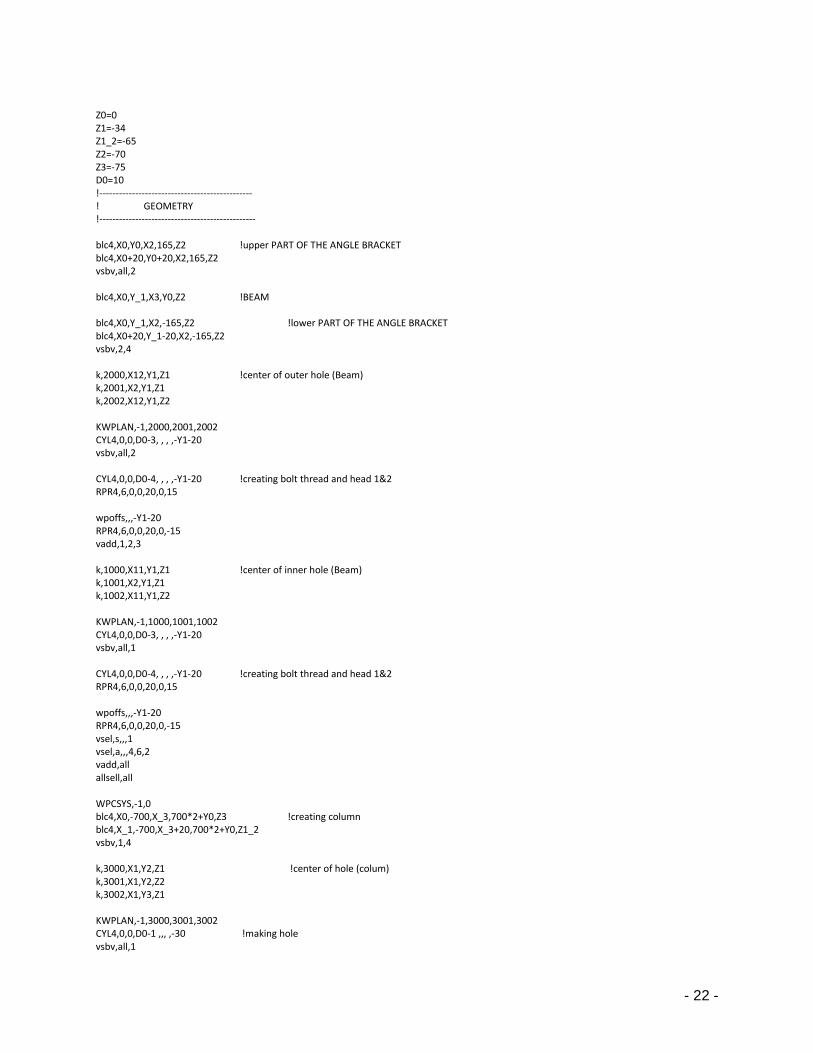
- 22 -
Z0=0 Z1=-34 Z1_2=-65 Z2=-70 Z3=-75 D0=10 !----------------------------------------------- ! GEOMETRY !------------------------------------------------ blc4,X0,Y0,X2,165,Z2 !upper PART OF THE ANGLE BRACKET blc4,X0+20,Y0+20,X2,165,Z2 vsbv,all,2 blc4,X0,Y_1,X3,Y0,Z2 !BEAM blc4,X0,Y_1,X2,-165,Z2 !lower PART OF THE ANGLE BRACKET blc4,X0+20,Y_1-20,X2,-165,Z2 vsbv,2,4 k,2000,X12,Y1,Z1 !center of outer hole (Beam) k,2001,X2,Y1,Z1 k,2002,X12,Y1,Z2 KWPLAN,-1,2000,2001,2002 CYL4,0,0,D0-3, , , ,-Y1-20 vsbv,all,2 CYL4,0,0,D0-4, , , ,-Y1-20 !creating bolt thread and head 1&2 RPR4,6,0,0,20,0,15 wpoffs,,,-Y1-20 RPR4,6,0,0,20,0,-15 vadd,1,2,3 k,1000,X11,Y1,Z1 !center of inner hole (Beam) k,1001,X2,Y1,Z1 k,1002,X11,Y1,Z2 KWPLAN,-1,1000,1001,1002 CYL4,0,0,D0-3, , , ,-Y1-20 vsbv,all,1 CYL4,0,0,D0-4, , , ,-Y1-20 !creating bolt thread and head 1&2 RPR4,6,0,0,20,0,15 wpoffs,,,-Y1-20 RPR4,6,0,0,20,0,-15 vsel,s,,,1 vsel,a,,,4,6,2 vadd,all allsell,all WPCSYS,-1,0 blc4,X0,-700,X_3,700*2+Y0,Z3 !creating column blc4,X_1,-700,X_3+20,700*2+Y0,Z1_2 vsbv,1,4 k,3000,X1,Y2,Z1 !center of hole (colum) k,3001,X1,Y2,Z2 k,3002,X1,Y3,Z1 KWPLAN,-1,3000,3001,3002 CYL4,0,0,D0-1 ,,, ,-30 !making hole vsbv,all,1

- 23 -
CYL4,0,0,D0-2 ,,, ,-30 !bolt with head RPR4,6,0,0,20,0,15 wpoffs,,,-30 RPR4,6,0,0,28,0,-15 vsel,s,,,1 vsel,a,,,3,6,3 vadd,all allsell,all wpoffs,,-(Y0+2*134) CYL4,0,0,D0-1,,, ,30 !making hol vsbv,all,1 CYL4,0,0,D0-2 ,,, ,30 !bolt with head RPR4,6,0,0,28,0,-15 wpoffs,,,30 RPR4,6,0,0,20,0,15 vsel,s,,,1 vsel,a,,,4,8,4 vadd,all allsell,all numcmp,all !................................................. ! mesh !................................................. ALLSEL,ALL !A_Bracket vsel,s,,,4,6,2 vatt,1,,1 ESIZE,10,0 MSHAPE,1,3D MSHKEY,0 VMESH,all ALLSEL,ALL !Beam vsel,s,,,1 vatt,2,,1 ESIZE,15,0, MSHAPE,1,3D MSHKEY,0 VMESH,all ALLSEL,ALL ALLSEL,ALL !Bolt vsel,s,,,3,5,2 !vsel,a,,,7,8 vatt,1,,1 ESIZE,5,0, MSHAPE,1,3D MSHKEY,0 VMESH,all ALLSEL,ALL ALLSEL,ALL !Bolt !vsel,s,,,3,5,2 vsel,s,,,7,8 vatt,1,,1 ESIZE,8,0, MSHAPE,1,3D MSHKEY,0 VMESH,all ALLSEL,ALL ALLSEL,ALL !column vsel,s,,,2 vatt,1,,1

- 24 -
ESIZE,15,0, MSHAPE,1,3D MSHKEY,0 VMESH,all ALLSEL,ALL Asel,s,area,,89 !top and bottom area of A_bracket nsla,s,1 NSEL,R,LOC,y,420,430 NREFINE,all, , ,2,0,1,1 ALLSEL,ALL Asel,s,area,,56 nsla,s,1 NSEL,R,LOC,x,15,25 NREFINE,all, , ,2,0,1,1 ALLSEL,ALL !_________________CONTACT PAIRS________________________ !_________________2________________________________ ET,2,conta174 ! CONTA173 ELEMENTS for bonded MPC ET,3,Targe170 ! TARGE170 ELEMENTS KEYOPT,2,2,2 KEYOPT,2,4,2 KEYOPT,2,12,5 TYPE,2 !contact element REAL,2 mat,1 allsel,all asel,s,area,,48 !outer bolt head and upper A_bracket nsla,s,1 ESLN,S ESURF TYPE,3 !Target element REAL,2 mat,1 ALLSEL,ALL Asel,s,area,,56 !top area of upper A_bracket nsla,s,1 NSEL,R,LOC,X,X12-25,X12+25 ESLN,S ESURF !___________________________________________________ !___________________3________________________________ ET,4,conta174 ! CONTA173 ELEMENTS for bonded MPC ET,5,Targe170 ! TARGE170 ELEMENTS KEYOPT,4,2,2 KEYOPT,4,4,2 KEYOPT,4,12,5 TYPE,4 !contact element REAL,4 mat,1 allsel,all asel,s,area,,47 !outer bolt head lower A_bracket nsla,s,1 ESLN,S ESURF TYPE,5 !Target element REAL,4 mat,1 ALLSEL,ALL Asel,s,area,,60 !bottom area of lower A_bracket nsla,s,1

- 25 -
NSEL,R,LOC,X,X12-25,X12+25 ESLN,S ESURF !_______________________________________________ !__________________4_________________________________ ET,6,conta174 ! CONTA173 ELEMENTS for bonded MPC ET,7,Targe170 ! TARGE170 ELEMENTS KEYOPT,6,2,2 KEYOPT,6,4,2 KEYOPT,6,12,5 TYPE,6 !contact element REAL,6 mat,1 allsel,all asel,s,area,,72 !bolt head upper nsla,s,1 ESLN,S ESURF TYPE,7 !Target element REAL,6 mat,1 ALLSEL,ALL Asel,s,area,,56 !bottom area of lower A_bracket nsla,s,1 NSEL,R,LOC,X,X11-25,X11+25 ESLN,S ESURF !_______________________________________________ !__________________5_________________________________ ET,8,conta174 ! CONTA173 ELEMENTS for bonded MPC ET,9,Targe170 ! TARGE170 ELEMENTS KEYOPT,8,2,2 KEYOPT,8,4,2 KEYOPT,8,12,5 TYPE,8 !contact element REAL,8 mat,1 allsel,all asel,s,area,,71 !bolt head upper nsla,s,1 ESLN,S ESURF TYPE,9 !Target element REAL,8 mat,1 ALLSEL,ALL Asel,s,area,,60 !bottom area of lower A_bracket nsla,s,1 NSEL,R,LOC,X,X11-25,X11+25 ESLN,S ESURF !_______________________________________________ !__________________6_________________________________ ET,10,conta174 ! CONTA173 ELEMENTS for bonded MPC ET,11,Targe170 ! TARGE170 ELEMENTS KEYOPT,10,2,2 KEYOPT,10,4,2 KEYOPT,10,12,5 TYPE,10 !contact element
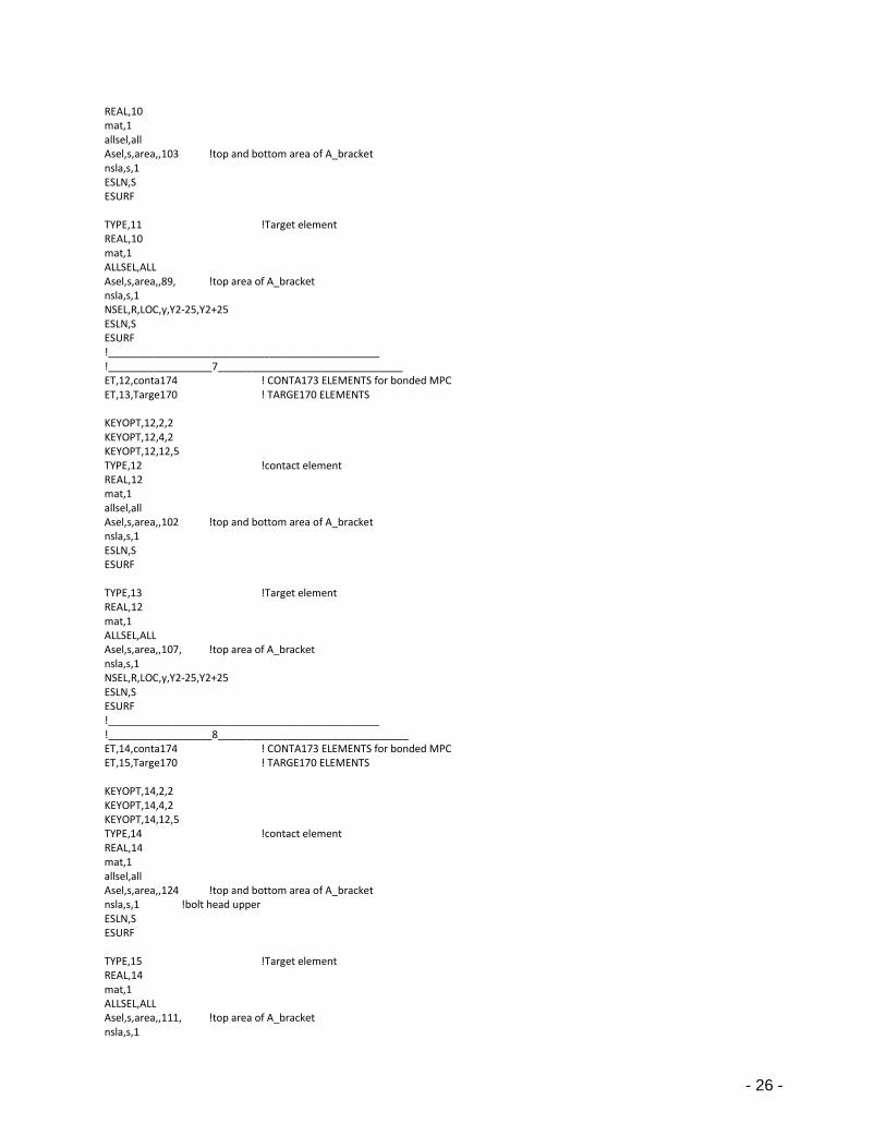
- 26 -
REAL,10 mat,1 allsel,all Asel,s,area,,103 !top and bottom area of A_bracket nsla,s,1 ESLN,S ESURF TYPE,11 !Target element REAL,10 mat,1 ALLSEL,ALL Asel,s,area,,89, !top area of A_bracket nsla,s,1 NSEL,R,LOC,y,Y2-25,Y2+25 ESLN,S ESURF !_______________________________________________ !__________________7________________________________ ET,12,conta174 ! CONTA173 ELEMENTS for bonded MPC ET,13,Targe170 ! TARGE170 ELEMENTS KEYOPT,12,2,2 KEYOPT,12,4,2 KEYOPT,12,12,5 TYPE,12 !contact element REAL,12 mat,1 allsel,all Asel,s,area,,102 !top and bottom area of A_bracket nsla,s,1 ESLN,S ESURF TYPE,13 !Target element REAL,12 mat,1 ALLSEL,ALL Asel,s,area,,107, !top area of A_bracket nsla,s,1 NSEL,R,LOC,y,Y2-25,Y2+25 ESLN,S ESURF !_______________________________________________ !__________________8_________________________________ ET,14,conta174 ! CONTA173 ELEMENTS for bonded MPC ET,15,Targe170 ! TARGE170 ELEMENTS KEYOPT,14,2,2 KEYOPT,14,4,2 KEYOPT,14,12,5 TYPE,14 !contact element REAL,14 mat,1 allsel,all Asel,s,area,,124 !top and bottom area of A_bracket nsla,s,1 !bolt head upper ESLN,S ESURF TYPE,15 !Target element REAL,14 mat,1 ALLSEL,ALL Asel,s,area,,111, !top area of A_bracket nsla,s,1

- 27 -
NSEL,R,LOC,y,-105,-156 ESLN,S ESURF !_______________________________________________ !__________________9_________________________________ ET,16,conta174 ! CONTA173 ELEMENTS for bonded MPC ET,17,Targe170 ! TARGE170 ELEMENTS KEYOPT,16,2,2 KEYOPT,16,4,2 KEYOPT,16,12,5 TYPE,16 !contact element REAL,16 mat,1 allsel,all Asel,s,area,,123 !top and bottom area of A_bracket nsla,s,1 !bolt head upper ESLN,S ESURF TYPE,17 !Target element REAL,16 mat,1 ALLSEL,ALL Asel,s,area,,107, !top area of A_bracket nsla,s,1 NSEL,R,LOC,y,-105,-156 ESLN,S ESURF !_______________________________________________ !__________________10________________________________ ET,18,conta174 ! CONTA173 ELEMENTS for bonded MPC ET,19,Targe170 ! TARGE170 ELEMENTS TYPE,18 !contact element REAL,18 mat,2 allsel,all Asel,s,area,,51 !top and bottom area of A_bracket nsla,s,1 !bolt head upper NSEL,R,LOC,x,0,X2+10 ESLN,S ESURF TYPE,19 !Target element REAL,18 mat,1 ALLSEL,ALL Asel,s,area,,55 !top area of A_bracket nsla,s,1 ESLN,S ESURF allsel,all !_______________________________________________ !__________________11________________________________ ET,20,conta174 ! CONTA173 ELEMENTS for bonded MPC ET,21,Targe170 ! TARGE170 ELEMENTS TYPE,20 !contact element REAL,20 mat,2 allsel,all Asel,s,area,,52 !top and bottom area of A_bracket nsla,s,1 !bolt head upper NSEL,R,LOC,x,0,X2+10 ESLN,S
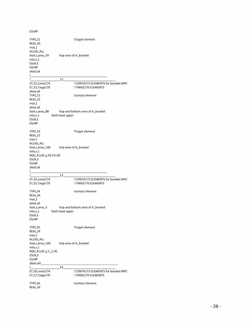
- 28 -
ESURF TYPE,21 !Target element REAL,20 mat,1 ALLSEL,ALL Asel,s,area,,59 !top area of A_bracket nsla,s,1 ESLN,S ESURF allsel,all !_______________________________________________ !__________________12________________________________ ET,22,conta174 ! CONTA173 ELEMENTS for bonded MPC ET,23,Targe170 ! TARGE170 ELEMENTS allsel,all TYPE,22 !contact element REAL,22 mat,1 allsel,all Asel,s,area,,88 !top and bottom area of A_bracket nsla,s,1 !bolt head upper ESLN,S ESURF TYPE,23 !Target element REAL,22 mat,1 ALLSEL,ALL Asel,s,area,,106 !top area of A_bracket nsla,s,1 NSEL,R,LOC,y,Y0,Y3+20 ESLN,S ESURF allsel,all !_______________________________________________ !__________________13________________________________ ET,24,conta174 ! CONTA173 ELEMENTS for bonded MPC ET,25,Targe170 ! TARGE170 ELEMENTS TYPE,24 !contact element REAL,24 mat,2 allsel,all Asel,s,area,,5 !top and bottom area of A_bracket nsla,s,1 !bolt head upper ESLN,S ESURF TYPE,25 !Target element REAL,24 mat,1 ALLSEL,ALL Asel,s,area,,106 !top area of A_bracket nsla,s,1 NSEL,R,LOC,y,Y_1,Y0, ESLN,S ESURF allsel,all!_______________________________________________ !__________________14________________________________ ET,26,conta174 ! CONTA173 ELEMENTS for bonded MPC ET,27,Targe170 ! TARGE170 ELEMENTS TYPE,26 !contact element REAL,26

- 29 -
mat,1 allsel,all Asel,s,area,,110 !top and bottom area of A_bracket nsla,s,1 !bolt head upper ESLN,S ESURF TYPE,27 !Target element REAL,26 mat,1 ALLSEL,ALL Asel,s,area,,106 !top area of A_bracket nsla,s,1 NSEL,R,LOC,y,-180,Y_1 ESLN,S ESURF allsel,all psmesh,,name,,volu,3,0,y,Y0/2,,,,elems psmesh,,name,,volu,5,0,y,Y0/2,,,,elems psmesh,,name,,volu,7,0,x,X0,,,,elems psmesh,,name,,volu,8,0,x,X0,,,,elems !_____________________________________________________ finish /solut antype,0 nlgeom,1 time,1 ! Sets time at end of run to 1 sec autots,on ! Auto time-stepping on nsubst,1,1,1 ! Number of sub-steps outres,all,1 ! Write all output neqit,300 nsel,s,loc,x,X_3 ! constrain NSEL,r,LOC,y,940,960 d,all,all allsel,all nsel,s,loc,x,X_3 ! constrain NSEL,r,LOC,y,-560,-540 d,all,all allsel,all asel,s,area,,1, nsla,s,1 D,all, , , , , ,UZ, , , , , Allsel,all asel,s,loc,z,0 DA,all,SYMM *DEL,_z *DIM,_z,ARRAY,2,1,1 *SET,_z(1) ,1 ,2 *DO,_z1,1,2 SLOAD,_z(_z1),9,tiny,FORC, 27000,1,2 *ENDDO *DEL,_z *DIM,_z,ARRAY,2,1,1 *SET,_z(1) ,3 ,4 *DO,_z1,1,2 SLOAD,_z(_z1),9,tiny,FORC, 39000,1,2 *ENDDO lswrite,1

- 30 -
time,1 ! Sets time at end of run to 1 sec autots,on ! Auto time-stepping on nsubst,10,10,10 ! Number of sub-steps outres,all,1 ! Write all output neqit,300 ALLSEL,ALL nsel,s,loc,x,X3 ! Apply load nsel,r,loc,y,Y0 D,all, ,-10, , , ,UY, , , , , allsel,all lswrite,2 lssolve,1,2,1

- 31 -
APPENDIX D !-----------The Model with 15mm Angle and 16mm vertical bolt (Case 4)----------------- FINISH /clear all /PREP7 !----------------------------------------------- ! properties !------------------------------------------------ ET,1,solid187 ET,2,conta174 ! CONTA173 ELEMENTS for bonded MPC ET,3,Targe170 ! TARGE170 ELEMENTS mp,ex,1,210000 !For steel mp,prxy,1,.3 MP,MU,1,.7 mp,prxy,2,.2 MP,MU,2,.7 !* MPTEMP,,,,,,,, MPTEMP,1,0 MPDE,NUXY,2 MPDE,NUYZ,2 MPDE,NUXZ,2 MPDE,PRXY,2 MPDE,PRYZ,2 MPDE,PRXZ,2 MPDE,EX,2 MPDATA,EX,2,,12100 !For glulam MPDATA,EY,2,,430 MPDATA,EZ,2,,430 MPDATA,PRXY,2,,0.2 MPDATA,PRYZ,2,,0.2 MPDATA,PRXZ,2,,0.2 MPDATA,GXY,2,,917 MPDATA,GYZ,2,,917 MPDATA,GXZ,2,,917 MPTEMP,,,,,,,, MPTEMP,1,0 MPDATA,DENS,2,,431 MPTEMP,,,,,,,, MPTEMP,1,0 MPDATA,DENS,1,,7800 !----------------------------------------------- ! DATA INPUT !------------------------------------------------ X0=0 X1=15 X11=99 X12=159 X2=215 X3=1875/4 ! 1/4 of beam is taken X_1=-10 X_2=-130 X_3=-150 Y0=405 Y1=15+Y0 Y2=131+Y0 Y3=165+Y0 Y4=500+Y0

- 32 -
Y_1=0 Z0=0 Z1=-34 Z1_2=-65 Z2=-70 Z3=-75 D0=10 !----------------------------------------------- ! GEOMETRY !------------------------------------------------ blc4,X0,Y0,X2,165,Z2 !upper PART OF THE ANGLE BRACKET blc4,X0+15,Y0+15,X2,165,Z2 vsbv,all,2 blc4,X0,Y_1,X3,Y0,Z2 !BEAM blc4,X0,Y_1,X2,-165,Z2 !lower PART OF THE ANGLE BRACKET blc4,X0+15,Y_1-15,X2,-165,Z2 vsbv,2,4 k,2000,X12,Y1,Z1 !center of outer hole (Beam) k,2001,X2,Y1,Z1 k,2002,X12,Y1,Z2 KWPLAN,-1,2000,2001,2002 CYL4,0,0,D0-1, , , ,-Y1-15 vsbv,all,2 CYL4,0,0,D0-2, , , ,-Y1-15 !creating bolt thread and head 1&2 RPR4,6,0,0,20,0,15 wpoffs,,,-Y1-15 RPR4,6,0,0,20,0,-15 vadd,1,2,3 k,1000,X11,Y1,Z1 !center of inner hole (Beam) k,1001,X2,Y1,Z1 k,1002,X11,Y1,Z2 KWPLAN,-1,1000,1001,1002 CYL4,0,0,D0-1, , , ,-Y1-15 vsbv,all,1 CYL4,0,0,D0-2, , , ,-Y1-15 !creating bolt thread and head 1&2 RPR4,6,0,0,20,0,15 wpoffs,,,-Y1-15 RPR4,6,0,0,20,0,-15 vsel,s,,,1 vsel,a,,,4,6,2 vadd,all allsell,all WPCSYS,-1,0 blc4,X0,-700,X_3,700*2+Y0,Z3 !creating column blc4,X_1,-700,X_3+20,700*2+Y0,Z1_2 vsbv,1,4 k,3000,X1,Y2,Z1 !center of hole (colum) k,3001,X1,Y2,Z2 k,3002,X1,Y3,Z1 KWPLAN,-1,3000,3001,3002

- 33 -
CYL4,0,0,D0-1 ,,, ,-25 !making hole vsbv,all,1 CYL4,0,0,D0-2 ,,, ,-25 !bolt with head RPR4,6,0,0,20,0,15 wpoffs,,,-25 RPR4,6,0,0,28,0,-15 vsel,s,,,1 vsel,a,,,3,6,3 vadd,all allsell,all wpoffs,,-(Y0+2*131) CYL4,0,0,D0-1,,, ,25 !making hol vsbv,all,1 CYL4,0,0,D0-2 ,,, ,25 !bolt with head RPR4,6,0,0,28,0,-15 wpoffs,,,25 RPR4,6,0,0,20,0,15 vsel,s,,,1 vsel,a,,,4,8,4 vadd,all allsell,all numcmp,all !................................................. ! mesh !................................................. ALLSEL,ALL !A_Bracket vsel,s,,,4,6,2 vatt,1,,1 ESIZE,10,0 MSHAPE,1,3D MSHKEY,0 VMESH,all Asel,s,area,,89 !top and bottom area of A_bracket nsla,s,1 NSEL,R,LOC,y,420,430 NREFINE,all, , ,2,0,1,1 ALLSEL,ALL Asel,s,area,,56 !top and bottom area of A_bracket nsla,s,1 NSEL,R,LOC,x,15,25 NREFINE,all, , ,2,0,1,1 ALLSEL,ALL ALLSEL,ALL !Beam vsel,s,,,1 vatt,2,,1 ESIZE,15,0, MSHAPE,1,3D MSHKEY,0 VMESH,all ALLSEL,ALL ALLSEL,ALL !Bolt vsel,s,,,3,5,2 !vsel,a,,,7,8 vatt,1,,1 ESIZE,5,0, MSHAPE,1,3D MSHKEY,0 VMESH,all ALLSEL,ALL

- 34 -
ALLSEL,ALL !Bolt !vsel,s,,,3,5,2 vsel,s,,,7,8 vatt,1,,1 ESIZE,8,0, MSHAPE,1,3D MSHKEY,0 VMESH,all ALLSEL,ALL ALLSEL,ALL !column vsel,s,,,2 vatt,1,,1 ESIZE,15,0, MSHAPE,1,3D MSHKEY,0 VMESH,all ALLSEL,ALL !_________________CONTACT PAIRS________________________ !_________________2________________________________ ET,2,conta174 ! CONTA173 ELEMENTS for bonded MPC ET,3,Targe170 ! TARGE170 ELEMENTS KEYOPT,2,2,2 KEYOPT,2,4,2 KEYOPT,2,12,5 TYPE,2 !contact element REAL,2 mat,1 allsel,all asel,s,area,,48 !outer bolt head and upper A_bracket nsla,s,1 ESLN,S ESURF TYPE,3 !Target element REAL,2 mat,1 ALLSEL,ALL Asel,s,area,,56 !top area of upper A_bracket nsla,s,1 NSEL,R,LOC,X,X12-25,X12+25 ESLN,S ESURF !___________________________________________________ !___________________3________________________________ ET,4,conta174 ! CONTA173 ELEMENTS for bonded MPC ET,5,Targe170 ! TARGE170 ELEMENTS KEYOPT,4,2,2 KEYOPT,4,4,2 KEYOPT,4,12,5 TYPE,4 !contact element REAL,4 mat,1 allsel,all asel,s,area,,47 !outer bolt head lower A_bracket nsla,s,1 ESLN,S ESURF TYPE,5 !Target element REAL,4 mat,1

- 35 -
ALLSEL,ALL Asel,s,area,,60 !bottom area of lower A_bracket nsla,s,1 NSEL,R,LOC,X,X12-25,X12+25 ESLN,S ESURF !_______________________________________________ !__________________4_________________________________ ET,6,conta174 ! CONTA173 ELEMENTS for bonded MPC ET,7,Targe170 ! TARGE170 ELEMENTS KEYOPT,6,2,2 KEYOPT,6,4,2 KEYOPT,6,12,5 TYPE,6 !contact element REAL,6 mat,1 allsel,all asel,s,area,,72 !bolt head upper nsla,s,1 ESLN,S ESURF TYPE,7 !Target element REAL,6 mat,1 ALLSEL,ALL Asel,s,area,,56 !bottom area of lower A_bracket nsla,s,1 NSEL,R,LOC,X,X11-25,X11+25 ESLN,S ESURF !_______________________________________________ !__________________5_________________________________ ET,8,conta174 ! CONTA173 ELEMENTS for bonded MPC ET,9,Targe170 ! TARGE170 ELEMENTS KEYOPT,8,2,2 KEYOPT,8,4,2 KEYOPT,8,12,5 TYPE,8 !contact element REAL,8 mat,1 allsel,all asel,s,area,,71 !bolt head upper nsla,s,1 ESLN,S ESURF TYPE,9 !Target element REAL,8 mat,1 ALLSEL,ALL Asel,s,area,,60 !bottom area of lower A_bracket nsla,s,1 NSEL,R,LOC,X,X11-25,X11+25 ESLN,S ESURF !_______________________________________________ !__________________6_________________________________ ET,10,conta174 ! CONTA173 ELEMENTS for bonded MPC ET,11,Targe170 ! TARGE170 ELEMENTS KEYOPT,10,2,2
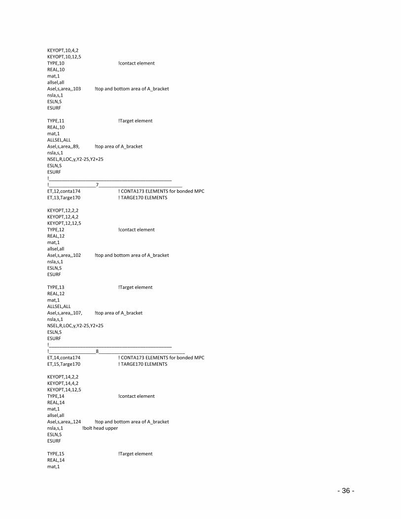
- 36 -
KEYOPT,10,4,2 KEYOPT,10,12,5 TYPE,10 !contact element REAL,10 mat,1 allsel,all Asel,s,area,,103 !top and bottom area of A_bracket nsla,s,1 ESLN,S ESURF TYPE,11 !Target element REAL,10 mat,1 ALLSEL,ALL Asel,s,area,,89, !top area of A_bracket nsla,s,1 NSEL,R,LOC,y,Y2-25,Y2+25 ESLN,S ESURF !_______________________________________________ !__________________7________________________________ ET,12,conta174 ! CONTA173 ELEMENTS for bonded MPC ET,13,Targe170 ! TARGE170 ELEMENTS KEYOPT,12,2,2 KEYOPT,12,4,2 KEYOPT,12,12,5 TYPE,12 !contact element REAL,12 mat,1 allsel,all Asel,s,area,,102 !top and bottom area of A_bracket nsla,s,1 ESLN,S ESURF TYPE,13 !Target element REAL,12 mat,1 ALLSEL,ALL Asel,s,area,,107, !top area of A_bracket nsla,s,1 NSEL,R,LOC,y,Y2-25,Y2+25 ESLN,S ESURF !_______________________________________________ !__________________8_________________________________ ET,14,conta174 ! CONTA173 ELEMENTS for bonded MPC ET,15,Targe170 ! TARGE170 ELEMENTS KEYOPT,14,2,2 KEYOPT,14,4,2 KEYOPT,14,12,5 TYPE,14 !contact element REAL,14 mat,1 allsel,all Asel,s,area,,124 !top and bottom area of A_bracket nsla,s,1 !bolt head upper ESLN,S ESURF TYPE,15 !Target element REAL,14 mat,1

- 37 -
ALLSEL,ALL Asel,s,area,,111, !top area of A_bracket nsla,s,1 NSEL,R,LOC,y,-105,-156 ESLN,S ESURF !_______________________________________________ !__________________9_________________________________ ET,16,conta174 ! CONTA173 ELEMENTS for bonded MPC ET,17,Targe170 ! TARGE170 ELEMENTS KEYOPT,16,2,2 KEYOPT,16,4,2 KEYOPT,16,12,5 TYPE,16 !contact element REAL,16 mat,1 allsel,all Asel,s,area,,123 !top and bottom area of A_bracket nsla,s,1 !bolt head upper ESLN,S ESURF TYPE,17 !Target element REAL,16 mat,1 ALLSEL,ALL Asel,s,area,,107, !top area of A_bracket nsla,s,1 NSEL,R,LOC,y,-105,-156 ESLN,S ESURF !_______________________________________________ !__________________10________________________________ ET,18,conta174 ! CONTA173 ELEMENTS for bonded MPC ET,19,Targe170 ! TARGE170 ELEMENTS TYPE,18 !contact element REAL,18 mat,2 allsel,all Asel,s,area,,51 !top and bottom area of A_bracket nsla,s,1 !bolt head upper NSEL,R,LOC,x,0,X2+10 ESLN,S ESURF TYPE,19 !Target element REAL,18 mat,1 ALLSEL,ALL Asel,s,area,,55 !top area of A_bracket nsla,s,1 ESLN,S ESURF allsel,all !_______________________________________________ !__________________11________________________________ ET,20,conta174 ! CONTA173 ELEMENTS for bonded MPC ET,21,Targe170 ! TARGE170 ELEMENTS TYPE,20 !contact element REAL,20 mat,2 allsel,all Asel,s,area,,52 !top and bottom area of A_bracket
- 38 -
nsla,s,1 !bolt head upper NSEL,R,LOC,x,0,X2+10 ESLN,S ESURF TYPE,21 !Target element REAL,20 mat,1 ALLSEL,ALL Asel,s,area,,59 !top area of A_bracket nsla,s,1 ESLN,S ESURF allsel,all !_______________________________________________ !__________________12________________________________ ET,22,conta174 ! CONTA173 ELEMENTS for bonded MPC ET,23,Targe170 ! TARGE170 ELEMENTS allsel,all TYPE,22 !contact element REAL,22 mat,1 allsel,all Asel,s,area,,88 !top and bottom area of A_bracket nsla,s,1 !bolt head upper ESLN,S ESURF TYPE,23 !Target element REAL,22 mat,1 ALLSEL,ALL Asel,s,area,,106 !top area of A_bracket nsla,s,1 NSEL,R,LOC,y,Y0,Y3+20 ESLN,S ESURF allsel,all !_______________________________________________ !__________________13________________________________ ET,24,conta174 ! CONTA173 ELEMENTS for bonded MPC ET,25,Targe170 ! TARGE170 ELEMENTS TYPE,24 !contact element REAL,24 mat,2 allsel,all Asel,s,area,,5 !top and bottom area of A_bracket nsla,s,1 !bolt head upper ESLN,S ESURF TYPE,25 !Target element REAL,24 mat,1 ALLSEL,ALL Asel,s,area,,106 !top area of A_bracket nsla,s,1 NSEL,R,LOC,y,Y_1,Y0, ESLN,S ESURF allsel,all!_______________________________________________ !__________________14________________________________ ET,26,conta174 ! CONTA173 ELEMENTS for bonded MPC ET,27,Targe170 ! TARGE170 ELEMENTS

- 39 -
TYPE,26 !contact element REAL,26 mat,1 allsel,all Asel,s,area,,110 !top and bottom area of A_bracket nsla,s,1 !bolt head upper ESLN,S ESURF TYPE,27 !Target element REAL,26 mat,1 ALLSEL,ALL Asel,s,area,,106 !top area of A_bracket nsla,s,1 NSEL,R,LOC,y,-180,Y_1 ESLN,S ESURF allsel,all psmesh,,name,,volu,3,0,y,Y0/2,,,,elems psmesh,,name,,volu,5,0,y,Y0/2,,,,elems psmesh,,name,,volu,7,0,x,X0,,,,elems psmesh,,name,,volu,8,0,x,X0,,,,elems !_____________________________________________________ finish /solut antype,0 nlgeom,1 time,1 ! Sets time at end of run to 1 sec autots,on ! Auto time-stepping on nsubst,1,1,1 ! Number of sub-steps outres,all,1 ! Write all output neqit,300 nsel,s,loc,x,X_3 ! constrain NSEL,r,LOC,y,940,960 d,all,all allsel,all nsel,s,loc,x,X_3 ! constrain NSEL,r,LOC,y,-560,-540 d,all,all allsel,all asel,s,area,,1, nsla,s,1 D,all, , , , , ,UZ, , , , , Allsel,all asel,s,loc,z,0 DA,all,SYMM *DEL,_z *DIM,_z,ARRAY,2,1,1 *SET,_z(1) ,1 ,2 *DO,_z1,1,2 SLOAD,_z(_z1),9,tiny,FORC, 20000,1,2 *ENDDO *DEL,_z *DIM,_z,ARRAY,2,1,1 *SET,_z(1) ,3 ,4 *DO,_z1,1,2 SLOAD,_z(_z1),9,tiny,FORC, 39000,1,2

- 40 -
*ENDDO lswrite,1 time,1 ! Sets time at end of run to 1 sec autots,on ! Auto time-stepping on nsubst,10,10,10 ! Number of sub-steps outres,all,1 ! Write all output neqit,300 ALLSEL,ALL nsel,s,loc,x,X3 ! Apply load nsel,r,loc,y,Y0 D,all, ,-10, , , ,UY, , , , , allsel,all lswrite,2 lssolve,1,2,1

- 41 -
APPENDIX E !-----------The Model with 15mm Angle and 20mmØ vertical bolt (Case 5)---------- FINISH /clear all /PREP7 !----------------------------------------------- ! properties !------------------------------------------------ ET,1,solid187 ET,2,conta174 ! CONTA173 ELEMENTS for bonded MPC ET,3,Targe170 ! TARGE170 ELEMENTS mp,ex,1,210000 !steel mp,prxy,1,.3 MP,MU,1,.7 mp,prxy,2,.2 MP,MU,2,.7 !* MPTEMP,,,,,,,, MPTEMP,1,0 MPDE,NUXY,2 MPDE,NUYZ,2 MPDE,NUXZ,2 MPDE,PRXY,2 MPDE,PRYZ,2 MPDE,PRXZ,2 MPDE,EX,2 MPDATA,EX,2,,12100 !glulam MPDATA,EY,2,,430 MPDATA,EZ,2,,430 MPDATA,PRXY,2,,0.2 MPDATA,PRYZ,2,,0.2 MPDATA,PRXZ,2,,0.2 MPDATA,GXY,2,,917 MPDATA,GYZ,2,,917 MPDATA,GXZ,2,,917 MPTEMP,,,,,,,, MPTEMP,1,0 MPDATA,DENS,2,,431 MPTEMP,,,,,,,, MPTEMP,1,0 MPDATA,DENS,1,,7800 !----------------------------------------------- ! DATA INPUT !------------------------------------------------ X0=0 X1=15 X11=99 X12=159 X2=215 X3=1875/4 ! 1/2 of beam is taken X_1=-10 X_2=-130 X_3=-150 Y0=405 Y1=15+Y0 Y2=131+Y0 Y3=165+Y0 Y4=500+Y0 !HEIGHT OF THE COLUM Y_1=0 Z0=0 Z1=-34 Z1_2=-65

- 42 -
Z2=-70 Z3=-75 D0=10 !----------------------------------------------- ! GEOMETRY !------------------------------------------------ blc4,X0,Y0,X2,165,Z2 !upper PART OF THE ANGLE BRACKET blc4,X0+15,Y0+15,X2,165,Z2 vsbv,all,2 blc4,X0,Y_1,X3,Y0,Z2 !BEAM blc4,X0,Y_1,X2,-165,Z2 !lower PART OF THE ANGLE BRACKET blc4,X0+15,Y_1-15,X2,-165,Z2 vsbv,2,4 k,2000,X12,Y1,Z1 !center of outer hole (Beam) k,2001,X2,Y1,Z1 k,2002,X12,Y1,Z2 KWPLAN,-1,2000,2001,2002 CYL4,0,0,D0+1, , , ,-Y1-15 vsbv,all,2 CYL4,0,0,D0, , , ,-Y1-15 !creating bolt thread and head 1&2 RPR4,6,0,0,20,0,15 wpoffs,,,-Y1-15 RPR4,6,0,0,20,0,-15 vadd,1,2,3 k,1000,X11,Y1,Z1 !center of inner hole (Beam) k,1001,X2,Y1,Z1 k,1002,X11,Y1,Z2 KWPLAN,-1,1000,1001,1002 CYL4,0,0,D0+1, , , ,-Y1-15 vsbv,all,1 CYL4,0,0,D0, , , ,-Y1-15 !creating bolt thread and head 1&2 RPR4,6,0,0,20,0,15 wpoffs,,,-Y1-15 RPR4,6,0,0,20,0,-15 vsel,s,,,1 vsel,a,,,4,6,2 vadd,all allsell,all WPCSYS,-1,0 blc4,X0,-700,X_3,700*2+Y0,Z3 blc4,X_1,-700,X_3+20,700*2+Y0,Z1_2 vsbv,1,4 k,3000,X1,Y2,Z1 !center of hole (colum) k,3001,X1,Y2,Z2 k,3002,X1,Y3,Z1 KWPLAN,-1,3000,3001,3002 CYL4,0,0,D0-1 ,,, ,-25 !making hole vsbv,all,1 CYL4,0,0,D0-2 ,,, ,-25 !bolt with head RPR4,6,0,0,20,0,15 wpoffs,,,-25 RPR4,6,0,0,28,0,-15

- 43 -
vsel,s,,,1 vsel,a,,,3,6,3 vadd,all allsell,all wpoffs,,-(Y0+2*131) CYL4,0,0,D0-1,,, ,25 !making hol vsbv,all,1 CYL4,0,0,D0-2 ,,, ,25 !bolt with head RPR4,6,0,0,28,0,-15 wpoffs,,,25 RPR4,6,0,0,20,0,15 vsel,s,,,1 vsel,a,,,4,8,4 vadd,all allsell,all numcmp,all !................................................. ! mesh !................................................. ALLSEL,ALL !A_Bracket vsel,s,,,4,6,2 vatt,1,,1 ESIZE,10,0 MSHAPE,1,3D MSHKEY,0 VMESH,all ALLSEL,ALL !Beam vsel,s,,,1 vatt,2,,1 ESIZE,15,0, MSHAPE,1,3D MSHKEY,0 VMESH,all ALLSEL,ALL ALLSEL,ALL !Bolt vsel,s,,,3,5,2 !vsel,a,,,7,8 vatt,1,,1 ESIZE,5,0, MSHAPE,1,3D MSHKEY,0 VMESH,all ALLSEL,ALL ALLSEL,ALL !Bolt !vsel,s,,,3,5,2 vsel,s,,,7,8 vatt,1,,1 ESIZE,8,0, MSHAPE,1,3D MSHKEY,0 VMESH,all ALLSEL,ALL ALLSEL,ALL !column vsel,s,,,2 vatt,1,,1 ESIZE,15,0, MSHAPE,1,3D MSHKEY,0 VMESH,all

- 44 -
ALLSEL,ALL Asel,s,area,,89 !top and bottom area of A_bracket nsla,s,1 NSEL,R,LOC,y,420,430 NREFINE,all, , ,2,0,1,1 ALLSEL,ALL Asel,s,area,,56 !top and bottom area of A_bracket nsla,s,1 NSEL,R,LOC,x,15,25 NREFINE,all, , ,2,0,1,1 ALLSEL,ALL !_________________CONTACT PAIRS________________________ !_________________2________________________________ ET,2,conta174 ! CONTA173 ELEMENTS for bonded MPC ET,3,Targe170 ! TARGE170 ELEMENTS KEYOPT,2,2,2 KEYOPT,2,4,2 KEYOPT,2,12,5 TYPE,2 !contact element REAL,2 mat,1 allsel,all asel,s,area,,48 !outer bolt head and upper A_bracket nsla,s,1 ESLN,S ESURF TYPE,3 !Target element REAL,2 mat,1 ALLSEL,ALL Asel,s,area,,56 !top area of upper A_bracket nsla,s,1 NSEL,R,LOC,X,X12-25,X12+25 ESLN,S ESURF !___________________________________________________ !___________________3________________________________ ET,4,conta174 ! CONTA173 ELEMENTS for bonded MPC ET,5,Targe170 ! TARGE170 ELEMENTS KEYOPT,4,2,2 KEYOPT,4,4,2 KEYOPT,4,12,5 TYPE,4 !contact element REAL,4 mat,1 allsel,all asel,s,area,,47 !outer bolt head lower A_bracket nsla,s,1 ESLN,S ESURF TYPE,5 !Target element REAL,4 mat,1 ALLSEL,ALL Asel,s,area,,60 !bottom area of lower A_bracket nsla,s,1 NSEL,R,LOC,X,X12-25,X12+25 ESLN,S ESURF !_______________________________________________
- 45 -
!__________________4_________________________________ ET,6,conta174 ! CONTA173 ELEMENTS for bonded MPC ET,7,Targe170 ! TARGE170 ELEMENTS KEYOPT,6,2,2 KEYOPT,6,4,2 KEYOPT,6,12,5 TYPE,6 !contact element REAL,6 mat,1 allsel,all asel,s,area,,72 !bolt head upper nsla,s,1 ESLN,S ESURF TYPE,7 !Target element REAL,6 mat,1 ALLSEL,ALL Asel,s,area,,56 !bottom area of lower A_bracket nsla,s,1 NSEL,R,LOC,X,X11-25,X11+25 ESLN,S ESURF !_______________________________________________ !__________________5_________________________________ ET,8,conta174 ! CONTA173 ELEMENTS for bonded MPC ET,9,Targe170 ! TARGE170 ELEMENTS KEYOPT,8,2,2 KEYOPT,8,4,2 KEYOPT,8,12,5 TYPE,8 !contact element REAL,8 mat,1 allsel,all asel,s,area,,71 !bolt head upper nsla,s,1 ESLN,S ESURF TYPE,9 !Target element REAL,8 mat,1 ALLSEL,ALL Asel,s,area,,60 !bottom area of lower A_bracket nsla,s,1 NSEL,R,LOC,X,X11-25,X11+25 ESLN,S ESURF !_______________________________________________ !__________________6_________________________________ ET,10,conta174 ! CONTA173 ELEMENTS for bonded MPC ET,11,Targe170 ! TARGE170 ELEMENTS KEYOPT,10,2,2 KEYOPT,10,4,2 KEYOPT,10,12,5 TYPE,10 !contact element REAL,10 mat,1 allsel,all Asel,s,area,,103 !top and bottom area of A_bracket

- 46 -
nsla,s,1 ESLN,S ESURF TYPE,11 !Target element REAL,10 mat,1 ALLSEL,ALL Asel,s,area,,89, !top area of A_bracket nsla,s,1 NSEL,R,LOC,y,Y2-25,Y2+25 ESLN,S ESURF !_______________________________________________ !__________________7________________________________ ET,12,conta174 ! CONTA173 ELEMENTS for bonded MPC ET,13,Targe170 ! TARGE170 ELEMENTS KEYOPT,12,2,2 KEYOPT,12,4,2 KEYOPT,12,12,5 TYPE,12 !contact element REAL,12 mat,1 allsel,all Asel,s,area,,102 !top and bottom area of A_bracket nsla,s,1 ESLN,S ESURF TYPE,13 !Target element REAL,12 mat,1 ALLSEL,ALL Asel,s,area,,107, !top area of A_bracket nsla,s,1 NSEL,R,LOC,y,Y2-25,Y2+25 ESLN,S ESURF !_______________________________________________ !__________________8_________________________________ ET,14,conta174 ! CONTA173 ELEMENTS for bonded MPC ET,15,Targe170 ! TARGE170 ELEMENTS KEYOPT,14,2,2 KEYOPT,14,4,2 KEYOPT,14,12,5 TYPE,14 !contact element REAL,14 mat,1 allsel,all Asel,s,area,,124 !top and bottom area of A_bracket nsla,s,1 !bolt head upper ESLN,S ESURF TYPE,15 !Target element REAL,14 mat,1 ALLSEL,ALL Asel,s,area,,111, !top area of A_bracket nsla,s,1 NSEL,R,LOC,y,-105,-156 ESLN,S ESURF !_______________________________________________
- 47 -
!__________________9_________________________________ ET,16,conta174 ! CONTA173 ELEMENTS for bonded MPC ET,17,Targe170 ! TARGE170 ELEMENTS KEYOPT,16,2,2 KEYOPT,16,4,2 KEYOPT,16,12,5 TYPE,16 !contact element REAL,16 mat,1 allsel,all Asel,s,area,,123 !top and bottom area of A_bracket nsla,s,1 !bolt head upper ESLN,S ESURF TYPE,17 !Target element REAL,16 mat,1 ALLSEL,ALL Asel,s,area,,107, !top area of A_bracket nsla,s,1 NSEL,R,LOC,y,-105,-156 ESLN,S ESURF !_______________________________________________ !__________________10________________________________ ET,18,conta174 ! CONTA173 ELEMENTS for bonded MPC ET,19,Targe170 ! TARGE170 ELEMENTS TYPE,18 !contact element REAL,18 mat,2 allsel,all Asel,s,area,,51 !top and bottom area of A_bracket nsla,s,1 !bolt head upper NSEL,R,LOC,x,0,X2+10 ESLN,S ESURF TYPE,19 !Target element REAL,18 mat,1 ALLSEL,ALL Asel,s,area,,55 !top area of A_bracket nsla,s,1 ESLN,S ESURF allsel,all !_______________________________________________ !__________________11________________________________ ET,20,conta174 ! CONTA173 ELEMENTS for bonded MPC ET,21,Targe170 ! TARGE170 ELEMENTS TYPE,20 !contact element REAL,20 mat,2 allsel,all Asel,s,area,,52 !top and bottom area of A_bracket nsla,s,1 !bolt head upper NSEL,R,LOC,x,0,X2+10 ESLN,S ESURF TYPE,21 !Target element REAL,20

- 48 -
mat,1 ALLSEL,ALL Asel,s,area,,59 !top area of A_bracket nsla,s,1 ESLN,S ESURF allsel,all !_______________________________________________ !__________________12________________________________ ET,22,conta174 ! CONTA173 ELEMENTS for bonded MPC ET,23,Targe170 ! TARGE170 ELEMENTS allsel,all TYPE,22 !contact element REAL,22 mat,1 allsel,all Asel,s,area,,88 !top and bottom area of A_bracket nsla,s,1 !bolt head upper ESLN,S ESURF TYPE,23 !Target element REAL,22 mat,1 ALLSEL,ALL Asel,s,area,,106 !top area of A_bracket nsla,s,1 NSEL,R,LOC,y,Y0,Y3+20 ESLN,S ESURF allsel,all !_______________________________________________ !__________________13________________________________ ET,24,conta174 ! CONTA173 ELEMENTS for bonded MPC ET,25,Targe170 ! TARGE170 ELEMENTS TYPE,24 !contact element REAL,24 mat,2 allsel,all Asel,s,area,,5 !top and bottom area of A_bracket nsla,s,1 !bolt head upper ESLN,S ESURF TYPE,25 !Target element REAL,24 mat,1 ALLSEL,ALL Asel,s,area,,106 !top area of A_bracket nsla,s,1 NSEL,R,LOC,y,Y_1,Y0, ESLN,S ESURF allsel,all!_______________________________________________ !__________________14________________________________ ET,26,conta174 ! CONTA173 ELEMENTS for bonded MPC ET,27,Targe170 ! TARGE170 ELEMENTS TYPE,26 !contact element REAL,26 mat,1 allsel,all Asel,s,area,,110 !top and bottom area of A_bracket nsla,s,1 !bolt head upper

- 49 -
ESLN,S ESURF TYPE,27 !Target element REAL,26 mat,1 ALLSEL,ALL Asel,s,area,,106 !top area of A_bracket nsla,s,1 NSEL,R,LOC,y,-180,Y_1 ESLN,S ESURF allsel,all psmesh,,name,,volu,3,0,y,Y0/2,,,,elems psmesh,,name,,volu,5,0,y,Y0/2,,,,elems psmesh,,name,,volu,7,0,x,X0,,,,elems psmesh,,name,,volu,8,0,x,X0,,,,elems !_____________________________________________________ finish /solut antype,0 nlgeom,1 time,1 ! Sets time at end of run to 1 sec autots,on ! Auto time-stepping on nsubst,1,1,1 ! Number of sub-steps outres,all,1 ! Write all output neqit,300 nsel,s,loc,x,X_3 ! constrain NSEL,r,LOC,y,940,960 d,all,all allsel,all nsel,s,loc,x,X_3 ! constrain NSEL,r,LOC,y,-560,-540 d,all,all allsel,all asel,s,area,,1, nsla,s,1 D,all, , , , , ,UZ, , , , , Allsel,all asel,s,loc,z,0 DA,all,SYMM *DEL,_z *DIM,_z,ARRAY,2,1,1 *SET,_z(1) ,1 ,2 *DO,_z1,1,2 SLOAD,_z(_z1),9,tiny,FORC, 16000,1,2 *ENDDO *DEL,_z *DIM,_z,ARRAY,2,1,1 *SET,_z(1) ,3 ,4 *DO,_z1,1,2 SLOAD,_z(_z1),9,tiny,FORC, 39000,1,2 *ENDDO lswrite,1 time,1 ! Sets time at end of run to 1 sec autots,on ! Auto time-stepping on nsubst,10,10,10 ! Number of sub-steps outres,all,1 ! Write all output

- 50 -
neqit,300 ALLSEL,ALL nsel,s,loc,x,X3 ! Apply load nsel,r,loc,y,Y0 D,all, ,-10, , , ,UY, , , , , allsel,all lswrite,2 lssolve,1,2,1

- 51 -
APPENDIX F !-----------The Model with reduced angle width(Case 6)------------------ FINISH /clear all /PREP7 !----------------------------------------------- ! properties !------------------------------------------------ ET,1,solid187 ET,2,conta174 ! CONTA173 ELEMENTS for bonded MPC ET,3,Targe170 ! TARGE170 ELEMENTS mp,ex,1,210000 !steel mp,prxy,1,.3 MP,MU,1,.7 mp,prxy,2,.2 MP,MU,2,.7 !* MPTEMP,,,,,,,, MPTEMP,1,0 MPDE,NUXY,2 MPDE,NUYZ,2 MPDE,NUXZ,2 MPDE,PRXY,2 MPDE,PRYZ,2 MPDE,PRXZ,2 MPDE,EX,2 MPDATA,EX,2,,12100 !steel MPDATA,EY,2,,430 MPDATA,EZ,2,,430 MPDATA,PRXY,2,,0.2 MPDATA,PRYZ,2,,0.2 MPDATA,PRXZ,2,,0.2 MPDATA,GXY,2,,917 MPDATA,GYZ,2,,917 MPDATA,GXZ,2,,917 MPTEMP,,,,,,,, MPTEMP,1,0 MPDATA,DENS,2,,431 MPTEMP,,,,,,,, MPTEMP,1,0 MPDATA,DENS,1,,7800 !----------------------------------------------- ! DATA INPUT !------------------------------------------------ X0=0 X1=15 X11=99 X12=159 X2=215 X3=1875/4 ! 1/4 of beam is taken X_1=-10 X_2=-130 X_3=-150 Y0=405 Y1=15+Y0 Y2=131+Y0 Y3=165+Y0 Y4=500+Y0 Y_1=0 Z0=0

- 52 -
Z1=-34 Z1_2=-65 Z2=-70 Z3=-75 D0=10 !----------------------------------------------- ! GEOMETRY !------------------------------------------------ blc4,X0,Y0,X2,165,Z2+10 !upper PART OF THE ANGLE BRACKET blc4,X0+15,Y0+15,X2,165,Z2+10 vsbv,all,2 blc4,X0,Y_1,X3,Y0,Z2 !BEAM blc4,X0,Y_1,X2,-165,Z2+10 !lower PART OF THE ANGLE BRACKET blc4,X0+15,Y_1-15,X2,-165,Z2+10 vsbv,2,4 k,2000,X12,Y1,Z1 !center of outer hole (Beam) k,2001,X2,Y1,Z1 k,2002,X12,Y1,Z2 KWPLAN,-1,2000,2001,2002 CYL4,0,0,D0-3, , , ,-Y1-15 vsbv,all,2 CYL4,0,0,D0-4, , , ,-Y1-15 !creating bolt thread and head 1&2 RPR4,6,0,0,20,0,15 wpoffs,,,-Y1-15 RPR4,6,0,0,20,0,-15 vadd,1,2,3 k,1000,X11,Y1,Z1 !center of inner hole (Beam) k,1001,X2,Y1,Z1 k,1002,X11,Y1,Z2 KWPLAN,-1,1000,1001,1002 CYL4,0,0,D0-3, , , ,-Y1-15 vsbv,all,1 CYL4,0,0,D0-4, , , ,-Y1-15 !creating bolt thread and head 1&2 RPR4,6,0,0,20,0,15 wpoffs,,,-Y1-15 RPR4,6,0,0,20,0,-15 vsel,s,,,1 vsel,a,,,4,6,2 vadd,all allsell,all WPCSYS,-1,0 blc4,X0,-700,X_3,700*2+Y0,Z3 !creating column blc4,X_1,-700,X_3+20,700*2+Y0,Z1_2 vsbv,1,4 k,3000,X1,Y2,Z1 !center of hole (colum) k,3001,X1,Y2,Z2 k,3002,X1,Y3,Z1 KWPLAN,-1,3000,3001,3002 CYL4,0,0,D0-1 ,,, ,-25 !making hole vsbv,all,1

- 53 -
CYL4,0,0,D0-2 ,,, ,-25 !bolt with head RPR4,6,0,0,20,0,15 wpoffs,,,-25 RPR4,6,0,0,28,0,-15 vsel,s,,,1 vsel,a,,,3,6,3 vadd,all allsell,all wpoffs,,-(Y0+2*131) CYL4,0,0,D0-1,,, ,25 !making hol vsbv,all,1 CYL4,0,0,D0-2 ,,, ,25 !bolt with head RPR4,6,0,0,28,0,-15 wpoffs,,,25 RPR4,6,0,0,20,0,15 vsel,s,,,1 vsel,a,,,4,8,4 vadd,all allsell,all numcmp,all !................................................. ! mesh !................................................. ALLSEL,ALL !A_Bracket vsel,s,,,4,6,2 vatt,1,,1 ESIZE,10,0 MSHAPE,1,3D MSHKEY,0 VMESH,all ALLSEL,ALL !Beam vsel,s,,,1 vatt,2,,1 ESIZE,15,0, MSHAPE,1,3D MSHKEY,0 VMESH,all ALLSEL,ALL ALLSEL,ALL !Bolt vsel,s,,,3,5,2 !vsel,a,,,7,8 vatt,1,,1 ESIZE,5,0, MSHAPE,1,3D MSHKEY,0 VMESH,all ALLSEL,ALL ALLSEL,ALL !Bolt !vsel,s,,,3,5,2 vsel,s,,,7,8 vatt,1,,1 ESIZE,8,0, MSHAPE,1,3D MSHKEY,0 VMESH,all ALLSEL,ALL ALLSEL,ALL !column vsel,s,,,2 vatt,1,,1

- 54 -
ESIZE,15,0, MSHAPE,1,3D MSHKEY,0 VMESH,all ALLSEL,ALL Asel,s,area,,89 !top and bottom area of A_bracket nsla,s,1 NSEL,R,LOC,y,420,430 NREFINE,all, , ,2,0,1,1 ALLSEL,ALL Asel,s,area,,56 !top and bottom area of A_bracket nsla,s,1 NSEL,R,LOC,x,15,25 NREFINE,all, , ,2,0,1,1 ALLSEL,ALL !_________________CONTACT PAIRS________________________ !_________________2________________________________ ET,2,conta174 ! CONTA173 ELEMENTS for bonded MPC ET,3,Targe170 ! TARGE170 ELEMENTS KEYOPT,2,2,2 KEYOPT,2,4,2 KEYOPT,2,12,5 TYPE,2 !contact element REAL,2 mat,1 allsel,all asel,s,area,,48 !outer bolt head and upper A_bracket nsla,s,1 ESLN,S ESURF TYPE,3 !Target element REAL,2 mat,1 ALLSEL,ALL Asel,s,area,,56 !top area of upper A_bracket nsla,s,1 NSEL,R,LOC,X,X12-25,X12+25 ESLN,S ESURF !___________________________________________________ !___________________3________________________________ ET,4,conta174 ! CONTA173 ELEMENTS for bonded MPC ET,5,Targe170 ! TARGE170 ELEMENTS KEYOPT,4,2,2 KEYOPT,4,4,2 KEYOPT,4,12,5 TYPE,4 !contact element REAL,4 mat,1 allsel,all asel,s,area,,47 !outer bolt head lower A_bracket nsla,s,1 ESLN,S ESURF TYPE,5 !Target element REAL,4 mat,1 ALLSEL,ALL Asel,s,area,,60 !bottom area of lower A_bracket

- 55 -
nsla,s,1 NSEL,R,LOC,X,X12-25,X12+25 ESLN,S ESURF !_______________________________________________ !__________________4_________________________________ ET,6,conta174 ! CONTA173 ELEMENTS for bonded MPC ET,7,Targe170 ! TARGE170 ELEMENTS KEYOPT,6,2,2 KEYOPT,6,4,2 KEYOPT,6,12,5 TYPE,6 !contact element REAL,6 mat,1 allsel,all asel,s,area,,72 !bolt head upper nsla,s,1 ESLN,S ESURF TYPE,7 !Target element REAL,6 mat,1 ALLSEL,ALL Asel,s,area,,56 !bottom area of lower A_bracket nsla,s,1 NSEL,R,LOC,X,X11-25,X11+25 ESLN,S ESURF !_______________________________________________ !__________________5_________________________________ ET,8,conta174 ! CONTA173 ELEMENTS for bonded MPC ET,9,Targe170 ! TARGE170 ELEMENTS KEYOPT,8,2,2 KEYOPT,8,4,2 KEYOPT,8,12,5 TYPE,8 !contact element REAL,8 mat,1 allsel,all asel,s,area,,71 !bolt head upper nsla,s,1 ESLN,S ESURF TYPE,9 !Target element REAL,8 mat,1 ALLSEL,ALL Asel,s,area,,60 !bottom area of lower A_bracket nsla,s,1 NSEL,R,LOC,X,X11-25,X11+25 ESLN,S ESURF !_______________________________________________ !__________________6_________________________________ ET,10,conta174 ! CONTA173 ELEMENTS for bonded MPC ET,11,Targe170 ! TARGE170 ELEMENTS KEYOPT,10,2,2 KEYOPT,10,4,2 KEYOPT,10,12,5

- 56 -
TYPE,10 !contact element REAL,10 mat,1 allsel,all Asel,s,area,,103 !top and bottom area of A_bracket nsla,s,1 ESLN,S ESURF TYPE,11 !Target element REAL,10 mat,1 ALLSEL,ALL Asel,s,area,,89, !top area of A_bracket nsla,s,1 NSEL,R,LOC,y,Y2-25,Y2+25 ESLN,S ESURF !_______________________________________________ !__________________7________________________________ ET,12,conta174 ! CONTA173 ELEMENTS for bonded MPC ET,13,Targe170 ! TARGE170 ELEMENTS KEYOPT,12,2,2 KEYOPT,12,4,2 KEYOPT,12,12,5 TYPE,12 !contact element REAL,12 mat,1 allsel,all Asel,s,area,,102 !top and bottom area of A_bracket nsla,s,1 ESLN,S ESURF TYPE,13 !Target element REAL,12 mat,1 ALLSEL,ALL Asel,s,area,,107, !top area of A_bracket nsla,s,1 NSEL,R,LOC,y,Y2-25,Y2+25 ESLN,S ESURF !_______________________________________________ !__________________8_________________________________ ET,14,conta174 ! CONTA173 ELEMENTS for bonded MPC ET,15,Targe170 ! TARGE170 ELEMENTS KEYOPT,14,2,2 KEYOPT,14,4,2 KEYOPT,14,12,5 TYPE,14 !contact element REAL,14 mat,1 allsel,all Asel,s,area,,124 !top and bottom area of A_bracket nsla,s,1 !bolt head upper ESLN,S ESURF TYPE,15 !Target element REAL,14 mat,1 ALLSEL,ALL Asel,s,area,,111, !top area of A_bracket

- 57 -
nsla,s,1 NSEL,R,LOC,y,-105,-156 ESLN,S ESURF !_______________________________________________ !__________________9_________________________________ ET,16,conta174 ! CONTA173 ELEMENTS for bonded MPC ET,17,Targe170 ! TARGE170 ELEMENTS KEYOPT,16,2,2 KEYOPT,16,4,2 KEYOPT,16,12,5 TYPE,16 !contact element REAL,16 mat,1 allsel,all Asel,s,area,,123 !top and bottom area of A_bracket nsla,s,1 !bolt head upper ESLN,S ESURF TYPE,17 !Target element REAL,16 mat,1 ALLSEL,ALL Asel,s,area,,107, !top area of A_bracket nsla,s,1 NSEL,R,LOC,y,-105,-156 ESLN,S ESURF !_______________________________________________ !__________________10________________________________ ET,18,conta174 ! CONTA173 ELEMENTS for bonded MPC ET,19,Targe170 ! TARGE170 ELEMENTS TYPE,18 !contact element REAL,18 mat,2 allsel,all Asel,s,area,,51 !top and bottom area of A_bracket nsla,s,1 !bolt head upper NSEL,R,LOC,x,0,X2+10 ESLN,S ESURF TYPE,19 !Target element REAL,18 mat,1 ALLSEL,ALL Asel,s,area,,55 !top area of A_bracket nsla,s,1 ESLN,S ESURF allsel,all !_______________________________________________ !__________________11________________________________ ET,20,conta174 ! CONTA173 ELEMENTS for bonded MPC ET,21,Targe170 ! TARGE170 ELEMENTS TYPE,20 !contact element REAL,20 mat,2 allsel,all Asel,s,area,,52 !top and bottom area of A_bracket nsla,s,1 !bolt head upper NSEL,R,LOC,x,0,X2+10

- 58 -
ESLN,S ESURF TYPE,21 !Target element REAL,20 mat,1 ALLSEL,ALL Asel,s,area,,59 !top area of A_bracket nsla,s,1 ESLN,S ESURF allsel,all !_______________________________________________ !__________________12________________________________ ET,22,conta174 ! CONTA173 ELEMENTS for bonded MPC ET,23,Targe170 ! TARGE170 ELEMENTS allsel,all TYPE,22 !contact element REAL,22 mat,1 allsel,all Asel,s,area,,88 !top and bottom area of A_bracket nsla,s,1 !bolt head upper ESLN,S ESURF TYPE,23 !Target element REAL,22 mat,1 ALLSEL,ALL Asel,s,area,,106 !top area of A_bracket nsla,s,1 NSEL,R,LOC,y,Y0,Y3+20 ESLN,S ESURF allsel,all !_______________________________________________ !__________________13________________________________ ET,24,conta174 ! CONTA173 ELEMENTS for bonded MPC ET,25,Targe170 ! TARGE170 ELEMENTS TYPE,24 !contact element REAL,24 mat,2 allsel,all Asel,s,area,,5 !top and bottom area of A_bracket nsla,s,1 !bolt head upper ESLN,S ESURF TYPE,25 !Target element REAL,24 mat,1 ALLSEL,ALL Asel,s,area,,106 !top area of A_bracket nsla,s,1 NSEL,R,LOC,y,Y_1,Y0, ESLN,S ESURF allsel,all!_______________________________________________ !__________________14________________________________ ET,26,conta174 ! CONTA173 ELEMENTS for bonded MPC ET,27,Targe170 ! TARGE170 ELEMENTS TYPE,26 !contact element REAL,26

- 59 -
mat,1 allsel,all Asel,s,area,,110 !top and bottom area of A_bracket nsla,s,1 !bolt head upper ESLN,S ESURF TYPE,27 !Target element REAL,26 mat,1 ALLSEL,ALL Asel,s,area,,106 !top area of A_bracket nsla,s,1 NSEL,R,LOC,y,-180,Y_1 ESLN,S ESURF allsel,all psmesh,,name,,volu,3,0,y,Y0/2,,,,elems psmesh,,name,,volu,5,0,y,Y0/2,,,,elems psmesh,,name,,volu,7,0,x,X0,,,,elems psmesh,,name,,volu,8,0,x,X0,,,,elems !_____________________________________________________ finish /solut antype,0 nlgeom,1 time,1 ! Sets time at end of run to 1 sec autots,on ! Auto time-stepping on nsubst,1,1,1 ! Number of sub-steps outres,all,1 ! Write all output neqit,300 nsel,s,loc,x,X_3 ! constrain NSEL,r,LOC,y,940,960 d,all,all allsel,all nsel,s,loc,x,X_3 ! constrain NSEL,r,LOC,y,-560,-540 d,all,all allsel,all asel,s,area,,1, nsla,s,1 D,all, , , , , ,UZ, , , , , Allsel,all asel,s,loc,z,0 DA,all,SYMM *DEL,_z *DIM,_z,ARRAY,2,1,1 *SET,_z(1) ,1 ,2 *DO,_z1,1,2 SLOAD,_z(_z1),9,tiny,FORC, 27000,1,2 *ENDDO *DEL,_z *DIM,_z,ARRAY,2,1,1 *SET,_z(1) ,3 ,4 *DO,_z1,1,2 SLOAD,_z(_z1),9,tiny,FORC, 39000,1,2 *ENDDO

- 60 -
lswrite,1 time,1 ! Sets time at end of run to 1 sec autots,on ! Auto time-stepping on nsubst,10,10,10 ! Number of sub-steps outres,all,1 ! Write all output neqit,300 ALLSEL,ALL nsel,s,loc,x,X3 ! Apply load nsel,r,loc,y,Y0 D,all, ,-10, , , ,UY, , , , , allsel,all lswrite,2 lssolve,1,2,1

- 61 -
APPENDIX G !-----------The Model with 12mm Angle and stiffner(Case 7)----------------- FINISH /clear all /PREP7 !----------------------------------------------- ! properties !------------------------------------------------ ET,1,solid187 ET,2,conta174 ! CONTA173 ELEMENTS for bonded MPC ET,3,Targe170 ! TARGE170 ELEMENTS mp,ex,1,210000 !steel mp,prxy,1,.3 MP,MU,1,.7 mp,prxy,2,.2 MP,MU,2,.7 !* MPTEMP,,,,,,,, MPTEMP,1,0 MPDE,NUXY,2 MPDE,NUYZ,2 MPDE,NUXZ,2 MPDE,PRXY,2 MPDE,PRYZ,2 MPDE,PRXZ,2 MPDE,EX,2 MPDATA,EX,2,,12100 !glulam MPDATA,EY,2,,430 MPDATA,EZ,2,,430 MPDATA,PRXY,2,,0.2 MPDATA,PRYZ,2,,0.2 MPDATA,PRXZ,2,,0.2 MPDATA,GXY,2,,917 MPDATA,GYZ,2,,917 MPDATA,GXZ,2,,917 MPTEMP,,,,,,,, MPTEMP,1,0 MPDATA,DENS,2,,431 MPTEMP,,,,,,,, MPTEMP,1,0 MPDATA,DENS,1,,7800 !----------------------------------------------- ! DATA INPUT !------------------------------------------------ X0=0 X1=12 X11=99 X12=159 X2=212 X3=1875/4 ! 1/4 of beam is taken X_1=-10 X_2=-130 X_3=-150 Y0=405 Y1=15+Y0-3 Y2=131+Y0-3 Y3=165+Y0-3 Y4=500+Y0 Y_1=0

- 62 -
Z0=0 Z1=-34 Z1_2=-65 Z2=-70 Z3=-75 D0=10 !----------------------------------------------- ! GEOMETRY !------------------------------------------------ blc4,X0,Y0,X2,162,Z2 !upper PART OF THE ANGLE BRACKET blc4,X0+12,Y0+12,X2,162,Z2 vsbv,all,2 blc4,X0,Y_1,X3,Y0,Z2 !BEAM blc4,X0,Y_1,X2,-162,Z2 !lower PART OF THE ANGLE BRACKET blc4,X0+12,Y_1-12,X2,-162,Z2 vsbv,2,4 k,2000,X12,Y1,Z1 !center of outer hole (Beam) k,2001,X2,Y1,Z1 k,2002,X12,Y1,Z2 KWPLAN,-1,2000,2001,2002 CYL4,0,0,D0-3, , , ,-Y1-12 vsbv,all,2 CYL4,0,0,D0-4, , , ,-Y1-12 !creating bolt thread and head 1&2 RPR4,6,0,0,20,0,15 wpoffs,,,-Y1-12 RPR4,6,0,0,20,0,-15 vadd,1,2,3 k,1000,X11,Y1,Z1 !center of inner hole (Beam) k,1001,X2,Y1,Z1 k,1002,X11,Y1,Z2 KWPLAN,-1,1000,1001,1002 CYL4,0,0,D0-3, , , ,-Y1-12 vsbv,all,1 CYL4,0,0,D0-4, , , ,-Y1-12 !creating bolt thread and head 1&2 RPR4,6,0,0,20,0,15 wpoffs,,,-Y1-12 RPR4,6,0,0,20,0,-15 vsel,s,,,1 vsel,a,,,4,6,2 vadd,all allsell,all WPCSYS,-1,0 blc4,X0,-700,X_3,2*700+Y0,Z3 blc4,X_1,-700,X_3+20,2*700+Y0,Z1_2 vsbv,1,4 k,3000,X1,Y2,Z1 !center of hole (colum) k,3001,X1,Y2,Z2 k,3002,X1,Y3,Z1 KWPLAN,-1,3000,3001,3002 CYL4,0,0,D0 ,,, ,-22 !making hole vsbv,all,1 CYL4,0,0,D0-1 ,,, ,-22 !bolt with head RPR4,6,0,0,20,0,15 wpoffs,,,-22 RPR4,6,0,0,28,0,-15

- 63 -
vsel,s,,,1 vsel,a,,,3,6,3 vadd,all allsell,all wpoffs,,-(Y0+2*128) CYL4,0,0,D0-1 ,,, ,22 !making hol vsbv,all,1 CYL4,0,0,D0-2 ,,, ,22 !bolt with head RPR4,6,0,0,28,0,-15 wpoffs,,,22 RPR4,6,0,0,20,0,15 vsel,s,,,1 vsel,a,,,4,8,4 vadd,all allsell,all WPCSYS,-1,0 k,4000,X1,Y1,Z0-7 !center of hole (colum) k,4001,X1+150,Y1,Z0-7 k,4002,X1,Y1+150,Z0-7 l,4000,4001 l,4001,4002 l,4002,4000 al,333,334,335 VOFFST,4,7, , VADD,1,9 numcmp,all !................................................. ! mesh !................................................. ALLSEL,ALL !A_Bracket vsel,s,,,3,5,2 vatt,1,,1 ESIZE,10,0 MSHAPE,1,3D MSHKEY,0 VMESH,all ALLSEL,ALL !Beam vsel,s,,,1 vatt,2,,1 ESIZE,15,0, MSHAPE,1,3D MSHKEY,0 VMESH,all ALLSEL,ALL ALLSEL,ALL !Bolt vsel,s,,,4,6,2 vatt,1,,1 ESIZE,5,0, MSHAPE,1,3D MSHKEY,0 VMESH,all ALLSEL,ALL ALLSEL,ALL !Bolt vsel,s,,,7,8 vatt,1,,1 ESIZE,8,0, MSHAPE,1,3D
- 64 -
MSHKEY,0 VMESH,all ALLSEL,ALL ALLSEL,ALL !column vsel,s,,,2 vatt,1,,1 ESIZE,15,0, MSHAPE,1,3D MSHKEY,0 VMESH,all ALLSEL,ALL !_________________CONTACT PAIRS________________________ !_________________2________________________________ ET,2,conta174 ! CONTA173 ELEMENTS for bonded MPC ET,3,Targe170 ! TARGE170 ELEMENTS KEYOPT,2,2,2 KEYOPT,2,4,2 KEYOPT,2,12,5 TYPE,2 !contact element REAL,2 mat,1 allsel,all asel,s,area,,48 !outer bolt head and upper A_bracket nsla,s,1 ESLN,S ESURF TYPE,3 !Target element REAL,2 mat,1 ALLSEL,ALL Asel,s,area,,127 !top area of upper A_bracket nsla,s,1 NSEL,R,LOC,X,X12-25,X12+25 ESLN,S ESURF !___________________________________________________ !___________________3________________________________ ET,4,conta174 ! CONTA173 ELEMENTS for bonded MPC ET,5,Targe170 ! TARGE170 ELEMENTS KEYOPT,4,2,2 KEYOPT,4,4,2 KEYOPT,4,12,5 TYPE,4 !contact element REAL,4 mat,1 allsel,all asel,s,area,,47 !outer bolt head lower A_bracket nsla,s,1 ESLN,S ESURF TYPE,5 !Target element REAL,4 mat,1 ALLSEL,ALL Asel,s,area,,59 !bottom area of lower A_bracket nsla,s,1 NSEL,R,LOC,X,X12-25,X12+25 ESLN,S ESURF !_______________________________________________ !__________________4_________________________________

- 65 -
ET,6,conta174 ! CONTA173 ELEMENTS for bonded MPC ET,7,Targe170 ! TARGE170 ELEMENTS KEYOPT,6,2,2 KEYOPT,6,4,2 KEYOPT,6,12,5 TYPE,6 !contact element REAL,6 mat,1 allsel,all asel,s,area,,71 !bolt head upper nsla,s,1 ESLN,S ESURF TYPE,7 !Target element REAL,6 mat,1 ALLSEL,ALL Asel,s,area,,127 !bottom area of lower A_bracket nsla,s,1 NSEL,R,LOC,X,X11-25,X11+25 ESLN,S ESURF !_______________________________________________ !__________________5_________________________________ ET,8,conta174 ! CONTA173 ELEMENTS for bonded MPC ET,9,Targe170 ! TARGE170 ELEMENTS KEYOPT,8,2,2 KEYOPT,8,4,2 KEYOPT,8,12,5 TYPE,8 !contact element REAL,8 mat,1 allsel,all asel,s,area,,70 !bolt head upper nsla,s,1 ESLN,S ESURF TYPE,9 !Target element REAL,8 mat,1 ALLSEL,ALL Asel,s,area,,59 !bottom area of lower A_bracket nsla,s,1 NSEL,R,LOC,X,X11-25,X11+25 ESLN,S ESURF !_______________________________________________ !__________________6_________________________________ ET,10,conta174 ! CONTA173 ELEMENTS for bonded MPC ET,11,Targe170 ! TARGE170 ELEMENTS KEYOPT,10,2,2 KEYOPT,10,4,2 KEYOPT,10,12,5 TYPE,10 !contact element REAL,10 mat,1 allsel,all Asel,s,area,,101 !top and bottom area of A_bracket nsla,s,1

- 66 -
ESLN,S ESURF TYPE,11 !Target element REAL,10 mat,1 ALLSEL,ALL Asel,s,area,,126, !top area of A_bracket nsla,s,1 NSEL,R,LOC,y,Y2-25,Y2+25 ESLN,S ESURF !_______________________________________________ !__________________7________________________________ ET,12,conta174 ! CONTA173 ELEMENTS for bonded MPC ET,13,Targe170 ! TARGE170 ELEMENTS KEYOPT,12,2,2 KEYOPT,12,4,2 KEYOPT,12,12,5 TYPE,12 !contact element REAL,12 mat,1 allsel,all Asel,s,area,,100 !top and bottom area of A_bracket nsla,s,1 ESLN,S ESURF TYPE,13 !Target element REAL,12 mat,1 ALLSEL,ALL Asel,s,area,,105, !top area of A_bracket nsla,s,1 NSEL,R,LOC,y,Y2-25,Y2+25 ESLN,S ESURF !_______________________________________________ !__________________8_________________________________ ET,14,conta174 ! CONTA173 ELEMENTS for bonded MPC ET,15,Targe170 ! TARGE170 ELEMENTS KEYOPT,14,2,2 KEYOPT,14,4,2 KEYOPT,14,12,5 TYPE,14 !contact element REAL,14 mat,1 allsel,all Asel,s,area,,123 !top and bottom area of A_bracket nsla,s,1 !bolt head upper ESLN,S ESURF TYPE,15 !Target element REAL,14 mat,1 ALLSEL,ALL Asel,s,area,,109, !top area of A_bracket nsla,s,1 NSEL,R,LOC,y,-105,-156 ESLN,S ESURF !_______________________________________________ !__________________9_________________________________

- 67 -
ET,16,conta174 ! CONTA173 ELEMENTS for bonded MPC ET,17,Targe170 ! TARGE170 ELEMENTS KEYOPT,16,2,2 KEYOPT,16,4,2 KEYOPT,16,12,5 TYPE,16 !contact element REAL,16 mat,1 allsel,all Asel,s,area,,122 !top and bottom area of A bracket nsla,s,1 !bolt head upper ESLN,S ESURF TYPE,17 !Target element REAL,16 mat,1 ALLSEL,ALL Asel,s,area,,105, !top area of A_bracket nsla,s,1 NSEL,R,LOC,y,-105,-156 ESLN,S ESURF !_______________________________________________ !__________________10________________________________ ET,18,conta174 ! CONTA173 ELEMENTS for bonded MPC ET,19,Targe170 ! TARGE170 ELEMENTS TYPE,18 !contact element REAL,18 mat,1 allsel,all Asel,s,area,,51 !top and bottom area of A_bracket nsla,s,1 !bolt head upper NSEL,R,LOC,x,0,X2+10 ESLN,S ESURF TYPE,19 !Target element REAL,18 mat,1 ALLSEL,ALL Asel,s,area,,55 !top area of A bracket nsla,s,1 ESLN,S ESURF allsel,all !_______________________________________________ !__________________11________________________________ ET,20,conta174 ! CONTA173 ELEMENTS for bonded MPC ET,21,Targe170 ! TARGE170 ELEMENTS TYPE,20 !contact element REAL,20 mat,1 allsel,all Asel,s,area,,52 !top and bottom area of A_bracket nsla,s,1 !bolt head upper NSEL,R,LOC,x,0,X2+10 ESLN,S ESURF TYPE,21 !Target element REAL,20 mat,1

- 68 -
ALLSEL,ALL Asel,s,area,,58 !top area of A_bracket nsla,s,1 ESLN,S ESURF allsel,all !_______________________________________________ !__________________12________________________________ ET,22,conta174 ! CONTA173 ELEMENTS for bonded MPC ET,23,Targe170 ! TARGE170 ELEMENTS allsel,all TYPE,22 !contact element REAL,22 mat,1 allsel,all Asel,s,area,,87 !top and bottom area of A_bracket nsla,s,1 !bolt head upper ESLN,S ESURF TYPE,23 !Target element REAL,22 mat,1 ALLSEL,ALL Asel,s,area,,104 !top area of A_bracket nsla,s,1 NSEL,R,LOC,y,Y0,Y3+20 ESLN,S ESURF allsel,all !_______________________________________________ !__________________13________________________________ ET,24,conta174 ! CONTA173 ELEMENTS for bonded MPC ET,25,Targe170 ! TARGE170 ELEMENTS TYPE,24 !contact element REAL,24 mat,1 allsel,all Asel,s,area,,7 !top and bottom area of A_bracket nsla,s,1 !bolt head upper ESLN,S ESURF TYPE,25 !Target element REAL,24 mat,1 ALLSEL,ALL Asel,s,area,,104 !top area of A_bracket nsla,s,1 NSEL,R,LOC,y,Y_1,Y0, ESLN,S ESURF allsel,all!_______________________________________________ !__________________14________________________________ ET,26,conta174 ! CONTA173 ELEMENTS for bonded MPC ET,27,Targe170 ! TARGE170 ELEMENTS TYPE,26 !contact element REAL,26 mat,1 allsel,all Asel,s,area,,108 !top and bottom area of A_bracket nsla,s,1 !bolt head upper ESLN,S

- 69 -
ESURF TYPE,27 !Target element REAL,26 mat,1 ALLSEL,ALL Asel,s,area,,104 !top area of A_bracket nsla,s,1 NSEL,R,LOC,y,-180,Y_1 ESLN,S ESURF allsel,all psmesh,,name,,volu,4,0,y,Y0/2,,,,elems psmesh,,name,,volu,6,0,y,Y0/2,,,,elems psmesh,,name,,volu,7,0,x,X0,,,,elems psmesh,,name,,volu,8,0,x,X0,,,,elems !___________________________________________________________ finish /solut antype,0 nlgeom,1 time,1 ! Sets time at end of run to 1 sec autots,on ! Auto time-stepping on nsubst,1,1,1 ! Number of sub-steps outres,all,all ! Write all output neqit,300 nsel,s,loc,x,X_3 ! constrain NSEL,r,LOC,y,940,960 d,all,all allsel,all nsel,s,loc,x,X_3 ! constrain NSEL,r,LOC,y,-560,-540 d,all,all allsel,all asel,s,area,,1, nsla,s,1 D,all, , , , , ,UZ, , , , , Allsel,all asel,s,loc,z,0 DA,all,SYMM *DEL,_z *DIM,_z,ARRAY,2,1,1 *SET,_z(1) ,1 ,2 *DO,_z1,1,2 SLOAD,_z(_z1),9,tiny,FORC, 27000,1,2 *ENDDO *DEL,_z *DIM,_z,ARRAY,2,1,1 *SET,_z(1) ,3 ,4 *DO,_z1,1,2 SLOAD,_z(_z1),9,tiny,FORC, 39000,1,2 *ENDDO lswrite,1 time,1 ! Sets time at end of run to 1 sec autots,on ! Auto time-stepping on nsubst,10,10,10 ! Number of sub-steps

- 70 -
outres,all,1 ! Write all output neqit,300 ALLSEL,ALL nsel,s,loc,x,X3 ! Apply load nsel,r,loc,y,Y0 D,all, ,-10, , , ,UY, , , , , allsel,all lswrite,2 lssolve,1,2,1

- 71 -
APPENDIX H !-----------The Model with combined Case3 and 5 ------------------ FINISH /clear all /PREP7 !----------------------------------------------- ! properties !------------------------------------------------ ET,1,solid187 ET,2,conta174 ! CONTA173 ELEMENTS for bonded MPC ET,3,Targe170 ! TARGE170 ELEMENTS mp,ex,1,210000 !steel mp,prxy,1,.3 MP,MU,1,.7 mp,prxy,2,.2 MP,MU,2,.7 !* MPTEMP,,,,,,,, MPTEMP,1,0 MPDE,NUXY,2 MPDE,NUYZ,2 MPDE,NUXZ,2 MPDE,PRXY,2 MPDE,PRYZ,2 MPDE,PRXZ,2 MPDE,EX,2 MPDATA,EX,2,,12100 MPDATA,EY,2,,430 MPDATA,EZ,2,,430 MPDATA,PRXY,2,,0.2 MPDATA,PRYZ,2,,0.2 MPDATA,PRXZ,2,,0.2 MPDATA,GXY,2,,917 MPDATA,GYZ,2,,917 MPDATA,GXZ,2,,917 MPTEMP,,,,,,,, MPTEMP,1,0 MPDATA,DENS,2,,431 MPTEMP,,,,,,,, MPTEMP,1,0 MPDATA,DENS,1,,7800 !----------------------------------------------- ! DATA INPUT !------------------------------------------------ X0=0 X1=20 X11=99 X12=159 X2=215 X3=1875/4 ! 1/2 of beam is taken X_1=-10 X_2=-130 X_3=-150 Y0=405 Y1=20+Y0 Y2=131+5+Y0 Y3=165+5+Y0 Y4=500+Y0 !HEIGHT OF THE COLUM Y_1=0 Z0=0

- 72 -
Z1=-34 Z1_2=-65 Z2=-70 Z3=-75 D0=10 !----------------------------------------------- ! GEOMETRY !------------------------------------------------ blc4,X0,Y0,X2,165,Z2 !upper PART OF THE ANGLE BRACKET blc4,X0+20,Y0+20,X2,165,Z2 vsbv,all,2 blc4,X0,Y_1,X3,Y0,Z2 !BEAM blc4,X0,Y_1,X2,-165,Z2 !lower PART OF THE ANGLE BRACKET blc4,X0+20,Y_1-20,X2,-165,Z2 vsbv,2,4 k,2000,X12,Y1,Z1 !center of outer hole (Beam) k,2001,X2,Y1,Z1 k,2002,X12,Y1,Z2 KWPLAN,-1,2000,2001,2002 CYL4,0,0,D0+1, , , ,-Y1-20 vsbv,all,2 CYL4,0,0,D0, , , ,-Y1-20 !creating bolt thread and head 1&2 RPR4,6,0,0,20,0,15 wpoffs,,,-Y1-20 RPR4,6,0,0,20,0,-15 vadd,1,2,3 k,1000,X11,Y1,Z1 !center of inner hole (Beam) k,1001,X2,Y1,Z1 k,1002,X11,Y1,Z2 KWPLAN,-1,1000,1001,1002 CYL4,0,0,D0+1, , , ,-Y1-20 vsbv,all,1 CYL4,0,0,D0, , , ,-Y1-20 !creating bolt thread and head 1&2 RPR4,6,0,0,20,0,15 wpoffs,,,-Y1-20 RPR4,6,0,0,20,0,-15 vsel,s,,,1 vsel,a,,,4,6,2 vadd,all allsell,all WPCSYS,-1,0 blc4,X0,-700,X_3,700*2+Y0,Z3 !-Y4 må byttes -200 blc4,X_1,-700,X_3+20,700*2+Y0,Z1_2 !2*(Y0+500)med400+Y0 vsbv,1,4 k,3000,X1,Y2,Z1 !center of hole (colum) k,3001,X1,Y2,Z2 k,3002,X1,Y3,Z1 KWPLAN,-1,3000,3001,3002 CYL4,0,0,D0-1 ,,, ,-30 !making hole vsbv,all,1 CYL4,0,0,D0-2 ,,, ,-30 !bolt with head RPR4,6,0,0,20,0,15

- 73 -
wpoffs,,,-30 RPR4,6,0,0,28,0,-15 vsel,s,,,1 vsel,a,,,3,6,3 vadd,all allsell,all wpoffs,,-(Y0+2*134) CYL4,0,0,D0-1,,, ,30 !making hol vsbv,all,1 CYL4,0,0,D0-2 ,,, ,30 !bolt with head RPR4,6,0,0,28,0,-15 wpoffs,,,30 RPR4,6,0,0,20,0,15 vsel,s,,,1 vsel,a,,,4,8,4 vadd,all allsell,all numcmp,all !................................................. ! mesh !................................................. ALLSEL,ALL !A_Bracket vsel,s,,,4,6,2 vatt,1,,1 ESIZE,10,0 MSHAPE,1,3D MSHKEY,0 VMESH,all ALLSEL,ALL !Beam vsel,s,,,1 vatt,2,,1 ESIZE,15,0, MSHAPE,1,3D MSHKEY,0 VMESH,all ALLSEL,ALL ALLSEL,ALL !Bolt vsel,s,,,3,5,2 !vsel,a,,,7,8 vatt,1,,1 ESIZE,5,0, MSHAPE,1,3D MSHKEY,0 VMESH,all ALLSEL,ALL ALLSEL,ALL !Bolt !vsel,s,,,3,5,2 vsel,s,,,7,8 vatt,1,,1 ESIZE,8,0, MSHAPE,1,3D MSHKEY,0 VMESH,all ALLSEL,ALL ALLSEL,ALL !column vsel,s,,,2 vatt,1,,1 ESIZE,15,0, MSHAPE,1,3D

- 74 -
MSHKEY,0 VMESH,all ALLSEL,ALL Asel,s,area,,89 !top and bottom area of A_bracket nsla,s,1 NSEL,R,LOC,y,420,430 NREFINE,all, , ,2,0,1,1 ALLSEL,ALL Asel,s,area,,56 !top and bottom area of A_bracket nsla,s,1 NSEL,R,LOC,x,15,25 NREFINE,all, , ,2,0,1,1 ALLSEL,ALL !_________________CONTACT PAIRS________________________ !_________________2________________________________ ET,2,conta174 ! CONTA173 ELEMENTS for bonded MPC ET,3,Targe170 ! TARGE170 ELEMENTS KEYOPT,2,2,2 KEYOPT,2,4,2 KEYOPT,2,12,5 TYPE,2 !contact element REAL,2 mat,1 allsel,all asel,s,area,,48 !outer bolt head and upper A_bracket nsla,s,1 ESLN,S ESURF TYPE,3 !Target element REAL,2 mat,1 ALLSEL,ALL Asel,s,area,,56 !top area of upper A_bracket nsla,s,1 NSEL,R,LOC,X,X12-25,X12+25 ESLN,S ESURF !___________________________________________________ !___________________3________________________________ ET,4,conta174 ! CONTA173 ELEMENTS for bonded MPC ET,5,Targe170 ! TARGE170 ELEMENTS KEYOPT,4,2,2 KEYOPT,4,4,2 KEYOPT,4,12,5 TYPE,4 !contact element REAL,4 mat,1 allsel,all asel,s,area,,47 !outer bolt head lower A_bracket nsla,s,1 ESLN,S ESURF TYPE,5 !Target element REAL,4 mat,1 ALLSEL,ALL Asel,s,area,,60 !bottom area of lower A_bracket nsla,s,1 NSEL,R,LOC,X,X12-25,X12+25 ESLN,S

- 75 -
ESURF !_______________________________________________ !__________________4_________________________________ ET,6,conta174 ! CONTA173 ELEMENTS for bonded MPC ET,7,Targe170 ! TARGE170 ELEMENTS KEYOPT,6,2,2 KEYOPT,6,4,2 KEYOPT,6,12,5 TYPE,6 !contact element REAL,6 mat,1 allsel,all asel,s,area,,72 !bolt head upper nsla,s,1 ESLN,S ESURF TYPE,7 !Target element REAL,6 mat,1 ALLSEL,ALL Asel,s,area,,56 !bottom area of lower A_bracket nsla,s,1 NSEL,R,LOC,X,X11-25,X11+25 ESLN,S ESURF !_______________________________________________ !__________________5_________________________________ ET,8,conta174 ! CONTA173 ELEMENTS for bonded MPC ET,9,Targe170 ! TARGE170 ELEMENTS KEYOPT,8,2,2 KEYOPT,8,4,2 KEYOPT,8,12,5 TYPE,8 !contact element REAL,8 mat,1 allsel,all asel,s,area,,71 !bolt head upper nsla,s,1 ESLN,S ESURF TYPE,9 !Target element REAL,8 mat,1 ALLSEL,ALL Asel,s,area,,60 !bottom area of lower A_bracket nsla,s,1 NSEL,R,LOC,X,X11-25,X11+25 ESLN,S ESURF !_______________________________________________ !__________________6_________________________________ ET,10,conta174 ! CONTA173 ELEMENTS for bonded MPC ET,11,Targe170 ! TARGE170 ELEMENTS KEYOPT,10,2,2 KEYOPT,10,4,2 KEYOPT,10,12,5 TYPE,10 !contact element REAL,10 mat,1

- 76 -
allsel,all Asel,s,area,,103 !top and bottom area of A_bracket nsla,s,1 ESLN,S ESURF TYPE,11 !Target element REAL,10 mat,1 ALLSEL,ALL Asel,s,area,,89, !top area of A_bracket nsla,s,1 NSEL,R,LOC,y,Y2-25,Y2+25 ESLN,S ESURF !_______________________________________________ !__________________7________________________________ ET,12,conta174 ! CONTA173 ELEMENTS for bonded MPC ET,13,Targe170 ! TARGE170 ELEMENTS KEYOPT,12,2,2 KEYOPT,12,4,2 KEYOPT,12,12,5 TYPE,12 !contact element REAL,12 mat,1 allsel,all Asel,s,area,,102 !top and bottom area of A_bracket nsla,s,1 ESLN,S ESURF TYPE,13 !Target element REAL,12 mat,1 ALLSEL,ALL Asel,s,area,,107, !top area of A_bracket nsla,s,1 NSEL,R,LOC,y,Y2-25,Y2+25 ESLN,S ESURF !_______________________________________________ !__________________8_________________________________ ET,14,conta174 ! CONTA173 ELEMENTS for bonded MPC ET,15,Targe170 ! TARGE170 ELEMENTS KEYOPT,14,2,2 KEYOPT,14,4,2 KEYOPT,14,12,5 TYPE,14 !contact element REAL,14 mat,1 allsel,all Asel,s,area,,124 !top and bottom area of A_bracket nsla,s,1 !bolt head upper ESLN,S ESURF TYPE,15 !Target element REAL,14 mat,1 ALLSEL,ALL Asel,s,area,,111, !top area of A_bracket nsla,s,1 NSEL,R,LOC,y,-105,-156 ESLN,S

- 77 -
ESURF !_______________________________________________ !__________________9_________________________________ ET,16,conta174 ! CONTA173 ELEMENTS for bonded MPC ET,17,Targe170 ! TARGE170 ELEMENTS KEYOPT,16,2,2 KEYOPT,16,4,2 KEYOPT,16,12,5 TYPE,16 !contact element REAL,16 mat,1 allsel,all Asel,s,area,,123 !top and bottom area of A_bracket nsla,s,1 !bolt head upper ESLN,S ESURF TYPE,17 !Target element REAL,16 mat,1 ALLSEL,ALL Asel,s,area,,107, !top area of A_bracket nsla,s,1 NSEL,R,LOC,y,-105,-156 ESLN,S ESURF !_______________________________________________ !__________________10________________________________ ET,18,conta174 ! CONTA173 ELEMENTS for bonded MPC ET,19,Targe170 ! TARGE170 ELEMENTS TYPE,18 !contact element REAL,18 mat,2 allsel,all Asel,s,area,,51 !top and bottom area of A_bracket nsla,s,1 !bolt head upper NSEL,R,LOC,x,0,X2+10 ESLN,S ESURF TYPE,19 !Target element REAL,18 mat,1 ALLSEL,ALL Asel,s,area,,55 !top area of A_bracket nsla,s,1 ESLN,S ESURF allsel,all !_______________________________________________ !__________________11________________________________ ET,20,conta174 ! CONTA173 ELEMENTS for bonded MPC ET,21,Targe170 ! TARGE170 ELEMENTS TYPE,20 !contact element REAL,20 mat,2 allsel,all Asel,s,area,,52 !top and bottom area of A_bracket nsla,s,1 !bolt head upper NSEL,R,LOC,x,0,X2+10 ESLN,S ESURF

- 78 -
TYPE,21 !Target element REAL,20 mat,1 ALLSEL,ALL Asel,s,area,,59 !top area of A_bracket nsla,s,1 ESLN,S ESURF allsel,all !_______________________________________________ !__________________12________________________________ ET,22,conta174 ! CONTA173 ELEMENTS for bonded MPC ET,23,Targe170 ! TARGE170 ELEMENTS allsel,all TYPE,22 !contact element REAL,22 mat,1 allsel,all Asel,s,area,,88 !top and bottom area of A_bracket nsla,s,1 !bolt head upper ESLN,S ESURF TYPE,23 !Target element REAL,22 mat,1 ALLSEL,ALL Asel,s,area,,106 !top area of A_bracket nsla,s,1 NSEL,R,LOC,y,Y0,Y3+20 ESLN,S ESURF allsel,all !_______________________________________________ !__________________13________________________________ ET,24,conta174 ! CONTA173 ELEMENTS for bonded MPC ET,25,Targe170 ! TARGE170 ELEMENTS TYPE,24 !contact element REAL,24 mat,2 allsel,all Asel,s,area,,5 !top and bottom area of A_bracket nsla,s,1 !bolt head upper ESLN,S ESURF TYPE,25 !Target element REAL,24 mat,1 ALLSEL,ALL Asel,s,area,,106 !top area of A_bracket nsla,s,1 NSEL,R,LOC,y,Y_1,Y0, ESLN,S ESURF allsel,all!_______________________________________________ !__________________14________________________________ ET,26,conta174 ! CONTA173 ELEMENTS for bonded MPC ET,27,Targe170 ! TARGE170 ELEMENTS TYPE,26 !contact element REAL,26 mat,1 allsel,all

- 79 -
Asel,s,area,,110 !top and bottom area of A_bracket nsla,s,1 !bolt head upper ESLN,S ESURF TYPE,27 !Target element REAL,26 mat,1 ALLSEL,ALL Asel,s,area,,106 !top area of A_bracket nsla,s,1 NSEL,R,LOC,y,-180,Y_1 ESLN,S ESURF allsel,all psmesh,,name,,volu,3,0,y,Y0/2,,,,elems psmesh,,name,,volu,5,0,y,Y0/2,,,,elems psmesh,,name,,volu,7,0,x,X0,,,,elems psmesh,,name,,volu,8,0,x,X0,,,,elems !_____________________________________________________ finish /solut antype,0 nlgeom,1 time,1 ! Sets time at end of run to 1 sec autots,on ! Auto time-stepping on nsubst,1,1,1 ! Number of sub-steps outres,all,1 ! Write all output neqit,300 nsel,s,loc,x,X_3 ! constrain NSEL,r,LOC,y,940,960 d,all,all allsel,all nsel,s,loc,x,X_3 ! constrain NSEL,r,LOC,y,-560,-540 d,all,all allsel,all asel,s,area,,1, nsla,s,1 D,all, , , , , ,UZ, , , , , Allsel,all asel,s,loc,z,0 DA,all,SYMM *DEL,_z *DIM,_z,ARRAY,2,1,1 *SET,_z(1) ,1 ,2 *DO,_z1,1,2 SLOAD,_z(_z1),9,tiny,FORC, 16000,1,2 *ENDDO *DEL,_z *DIM,_z,ARRAY,2,1,1 *SET,_z(1) ,3 ,4 *DO,_z1,1,2 SLOAD,_z(_z1),9,tiny,FORC, 39000,1,2 *ENDDO lswrite,1 time,1 ! Sets time at end of run to 1 sec

- 80 -
autots,on ! Auto time-stepping on nsubst,10,10,10 ! Number of sub-steps outres,all,1 ! Write all output neqit,300 ALLSEL,ALL nsel,s,loc,x,X3 ! Apply load nsel,r,loc,y,Y0 D,all, ,-10, , , ,UY, , , , , !f,all,fy,-10000 allsel,all lswrite,2 lssolve,1,2,1

- 81 -
