and fixing systems - glass · pdf filewith unique exclusive standard and connecting panels,...
TRANSCRIPT
GLASS BLOCK TECHNOLOGY
AND FIXING SYSTEMSPREFABRICATED WALL PANELS
1109-Precast-A4-12pp 9/12/05 5:27 PM Page 1

INTRODUCTION
Glass Block Technology’s range of Precast systems are designed to offer solutions to the UK construction industry, with unique exclusive standard and connecting panels, restraint and fixing systems.
Precast can be considered for most glass block applications, for internal, external, fire rated and flooring specifications.Most projects can be undertaken using standard size or connecting precast panels that are manufactured under factorycontrolled conditions, ensuring regularity of joints whilst guaranteeing a first class, premium finish.
Glass Block Technology specialise in supplying, researching and are constantly developing solutions to complete allmanner of projects. Weather conditions are not an issue that affect the installation of external glass block precast unitsunlike insitu construction.
They can be used to allow natural daylight to flow from room to room, side of doorways, shower screens, and breakfastbars, to increase security or purely for aesthetical appeal.
Precast wall panels offer many benefits :• Uniformity of joints • Modular dry fix panels• Ease and speed of installation • Made to measure/Standard size panels• The advantages of quality control
2
PRECAST PANELSMAKE A
DIFFERENCE
In France, approximately 70-75% of glass block projects undertaken are installed using precast as opposed toloose build insitu construction. (La Rochere, a French glass block manufacturer, has produced precast since the 1970’s,they offer 3 or 4 fixing systems.)
Glass Block Technology have invented solutions more suitable to the UK market.
Car Park, France Football training ground, Stuttgart
St Andrews Gibson Terrace
1109-Precast-A4-12pp 9/12/05 5:28 PM Page 2

PRECAST PANEL SPECIFICATION
Glass block walls are self supporting, but not load bearing. Therefore similar to doors & windows, support aboveshould be provided in the form of a lintel.
For best integral strength, glass blocks should ideally be installed into a four sided pre-prepared opening. Thisopening can be timber, brick, steel, concrete or block work.
Glass blocks expand and contract with temperature change. Expansion material must be incorporated to theperimeter opening and intermittently between vertical of horizontal joints if a panel exceeds 6m in any direction.Perimeter expansion should be weatherproofed.
Openings must be square and perpendicular and made to suit glass block panels.
The maximum panel size does vary for precast installation based upon design (consult GBT).
The specification of precast panels may be limited by handling, site access and lifting.
3
When specifying Precast Wall panels, important criteria should be considered:
• Type of precast (concrete, Easifix or fire rated) • Calculating of opening sizes• Restraint/clamping panels in place • Fire ratings• How panels connect together.
TEL : 0161 612 6893 FAX : 0161 285 1503 SALES OFFICE : 170 Lodge Lane, Hyde, Cheshire SK14 4LB TECHNICAL OFFICE TEL : 01746 780026 FAX : 01746 781704 WEB : www.glassblocks.co.uk E-MAIL : [email protected]
✓
✓
✓
✓
✓
✓
GOLDEN RULES OF GLASS BLOCK SPECIFICATION TO CONSIDER
BORDERSConcrete wall panels have to be produced with a border to theperimeter edge of the panel. These are vital for the purpose ofrestraint aswell as production and handling. They are also a
condition of some fire rated panels(in accordance with manufacturerstest data). Generally border widthsfor precast panels are 35mm. Themaximum width is dependent onthe panel (wall, floor or fire rated)or block type. Please contact GBTfor further assistance regardingmaximum border widths. F30 andF60 fire rated panels aremanufactured with 50mm borders.
JOINTSConcrete wall panels are generally manufacturedwith 10mm joints, however this can be decreased toas little as 6mm or increased to around 20mm.
20mm joints10mm joints
TYPES OF PANEL PRODUCED
Vertical connectingOne piece
Panels can be produced incorporating all types of glass block dimensions, the most commonbeing 190x190x80mm, see La Rochere range, visit www.glassblocks.co.uk /range,190x190x100mm, 190x90x80mm (1/2 blocks), 240x240mm and fire blocks.
Wall panels cannot be used for horizontal applications like roof lights. For roof lights/floor pavers, visit www.glassblocks.co.uk/floorpanels
35mm border width
Horizontal connecting
STANDARD CONNECTING
1109-Precast-A4-12pp 9/12/05 5:28 PM Page 3
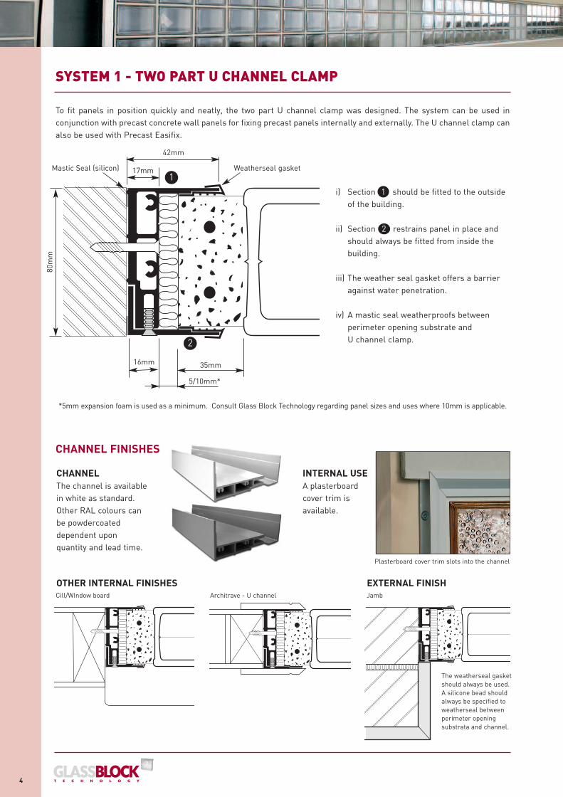
i) Section 1 should be fitted to the outside of the building.
ii) Section 2 restrains panel in place and should always be fitted from inside the building.
iii) The weather seal gasket offers a barrier against water penetration.
iv) A mastic seal weatherproofs between perimeter opening substrate andU channel clamp.
SYSTEM 1 - TWO PART U CHANNEL CLAMP
4
1
2
80m
m
35mm16mm
Weatherseal gasketMastic Seal (silicon)
*5mm expansion foam is used as a minimum. Consult Glass Block Technology regarding panel sizes and uses where 10mm is applicable.
5/10mm*
17mm
42mm
To fit panels in position quickly and neatly, the two part U channel clamp was designed. The system can be used inconjunction with precast concrete wall panels for fixing precast panels internally and externally. The U channel clamp canalso be used with Precast Easifix.
CHANNEL FINISHES
CHANNELThe channel is availablein white as standard.Other RAL colours canbe powdercoateddependent uponquantity and lead time.
OTHER INTERNAL FINISHES
Plasterboard cover trim slots into the channel
Cill/WIndow board JambArchitrave - U channel
EXTERNAL FINISH
The weatherseal gasketshould always be used.A silicone bead shouldalways be specified toweatherseal betweenperimeter openingsubstrata and channel.
INTERNAL USEA plasterboardcover trim isavailable.
1109-Precast-A4-12pp 9/12/05 5:28 PM Page 4

5
SYSTEM 1 - TWO PART U CHANNEL CLAMP
TEL : 0161 612 6893 FAX : 0161 285 1503 SALES OFFICE : 170 Lodge Lane, Hyde, Cheshire SK14 4LB TECHNICAL OFFICE TEL : 01746 780026 FAX : 01746 781704 WEB : www.glassblocks.co.uk E-MAIL : [email protected]
CALCULATING OPENING SIZE FOR PRECAST WALL PANEL & TWO PART U CHANNEL CLAMP
Example based on a panel of 5 blocks wide x 5 blocks high using 190x190x80mm blocks with 10mm joints,35mm borders, 5mm expansion fibre and two-part U channel clamps.
PANEL SIZE (x)5 no. blocks x 190mm = 950mm4 no. joints x 10mm = 40mm2 no. borders x 35mm = 70mm
Panel size (x) dimension 1060mm
OPENING SIZE (y)Panel width/height = 1060mm2 no. vertical/horizontal expansion joints x 5mm = 10mm2 no. two-part U channel clamp base x 17mm = 34mm2 no. tolerance allowance x 5mm 10mm
Opening size (x) and (y) dimension 1114mm
Panel size (x)
Structuralopening
(y)
35m
m b
orde
r w
idth
5mm toleranceeither side filledusing siliconesealant to act asweatherseal
42m
mU
cha
nnel
clam
p w
idth
PANEL SIZE• Only 80mm thick glass blocks can be used with System 1
(Two Part U Channel Clamp).• 35mm borders offer the best fit and are aesthetically
more pleasing.• Panels exceeding 6m in any direction should be split
using intermediate support/slip joints.
Expansion material should always be incorporated inside thechannel, expansion fibre across the head, down both jambs andbitumen at the base to support the weight of the panel.8mm bitumen and 5mm expansion foam. If the panel exceeds4m in width or height 10mm expansion foam may need to beused, consult GBT. Golden rules of glass block specificationshould be considered.
When calculating opening sizes for precast wall panels it is
critical that the correct dimensions are specified/detailed.
GBT can offer full assistance with this.The six key areas to consider are:
• Block size • Joint width • Border width
• Expansion fibre width • Restraint/clamp system width • Tolerance
SPECIFYING TWO PART U CHANNEL CLAMP
10m
m jo
int w
idth
1109-Precast-A4-12pp 9/12/05 5:28 PM Page 5

INTERCONNECTING PRECAST WALL PANELS
Location of sponge indicated in red
Sponge
Sponge
6
PREPARATION OF THE OPENING
Precast panels are delivered on pallets. Beforecutting the banding, ensure adequate support to bothsides. The panels are clearly labelled to face side. It is advisedthat the panels be manoeuvred close to the location of installationprior to removing protective timber casing.
Each installation of Precast wall panel varies, depending on type, access,internal or external, fire or non-fire rated and which installation/restraintsystem is being used.
The following section is divided into two categories:1. How horizontal/vertical connecting panels are manufactured.2. How horizontal connecting panels are positioned, fitted in place andfinished.
Horizontal and vertical precast concrete panels are produced with a sectionof the connecting joint missing for practical, safe connection.The location of connecting joints is decided by GBT Precast Department,based on the nature of project in respect of panel size, panel location.lifting and fitting (either mechanical or manual) and panel weights(based upon block specification).
See step by step instructions for information regarding howconnecting panels are constructed and finished.
SYSTEM 1 - TWO PART U CHANNEL CLAMP
1109-Precast-A4-12pp 9/12/05 5:28 PM Page 6
7
SYSTEM 1 - TWO PART U CHANNEL CLAMP
TEL : 0161 612 6893 FAX : 0161 285 1503 SALES OFFICE : 170 Lodge Lane, Hyde, Cheshire SK14 4LB TECHNICAL OFFICE TEL : 01746 780026 FAX : 01746 781704 WEB : www.glassblocks.co.uk E-MAIL : [email protected]
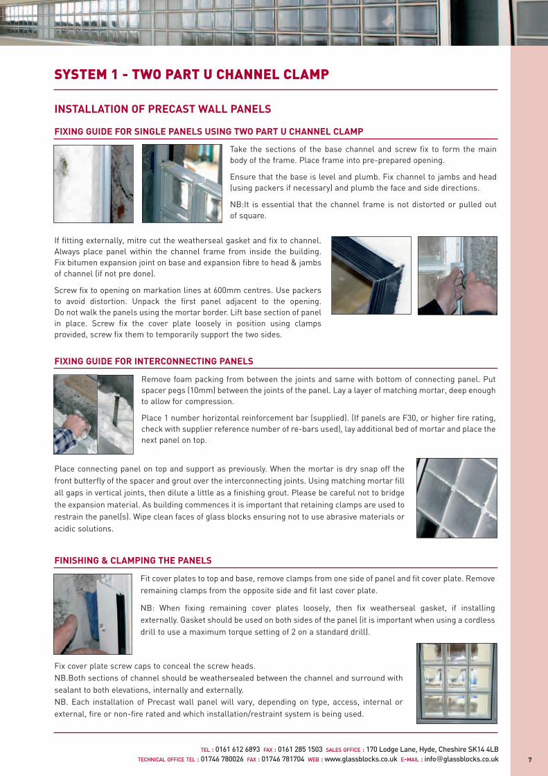
FIXING GUIDE FOR SINGLE PANELS USING TWO PART U CHANNEL CLAMP
INSTALLATION OF PRECAST WALL PANELS
FIXING GUIDE FOR INTERCONNECTING PANELS
FINISHING & CLAMPING THE PANELS
If fitting externally, mitre cut the weatherseal gasket and fix to channel.Always place panel within the channel frame from inside the building.Fix bitumen expansion joint on base and expansion fibre to head & jambsof channel (if not pre done).
Screw fix to opening on markation lines at 600mm centres. Use packersto avoid distortion. Unpack the first panel adjacent to the opening.Do not walk the panels using the mortar border. Lift base section of panelin place. Screw fix the cover plate loosely in position using clampsprovided, screw fix them to temporarily support the two sides.
Remove foam packing from between the joints and same with bottom of connecting panel. Putspacer pegs (10mm) between the joints of the panel. Lay a layer of matching mortar, deep enoughto allow for compression.
Place 1 number horizontal reinforcement bar (supplied). (If panels are F30, or higher fire rating,check with supplier reference number of re-bars used), lay additional bed of mortar and place thenext panel on top.
Fit cover plates to top and base, remove clamps from one side of panel and fit cover plate. Removeremaining clamps from the opposite side and fit last cover plate.
NB: When fixing remaining cover plates loosely, then fix weatherseal gasket, if installingexternally. Gasket should be used on both sides of the panel (it is important when using a cordlessdrill to use a maximum torque setting of 2 on a standard drill).
Take the sections of the base channel and screw fix to form the mainbody of the frame. Place frame into pre-prepared opening.
Ensure that the base is level and plumb. Fix channel to jambs and head(using packers if necessary) and plumb the face and side directions.
NB:It is essential that the channel frame is not distorted or pulled outof square.
Place connecting panel on top and support as previously. When the mortar is dry snap off thefront butterfly of the spacer and grout over the interconnecting joints. Using matching mortar fillall gaps in vertical joints, then dilute a little as a finishing grout. Please be careful not to bridgethe expansion material. As building commences it is important that retaining clamps are used torestrain the panel(s). Wipe clean faces of glass blocks ensuring not to use abrasive materials oracidic solutions.
Fix cover plate screw caps to conceal the screw heads. NB.Both sections of channel should be weathersealed between the channel and surround withsealant to both elevations, internally and externally. NB. Each installation of Precast wall panel will vary, depending on type, access, internal orexternal, fire or non-fire rated and which installation/restraint system is being used.
1109-Precast-A4-12pp 9/12/05 5:28 PM Page 7

8
SYSTEM 2 - FIRE RATED PRECAST CONCRETE WALL PANELS
Precast concrete wall panels can be manufactured to suit various fire ratings: G60/FI5, G60/F30 and G60/F60. (G60/F90 upon application).
Fire rated glass blocks are used in various areas and in all market sectors,usually in compartmentalised areas, fire escape routes, third storey loftconversions and external boundary walls in close proximity to other buildingsor public highways.
Fire rated panels are usually specified via an architect or a condition instructedby building control under building regulations.
Fire rated panels are available in Precast format, ensuring correct installationrequirements in line with test data, also ensuring regularity of joints and apremium quality factory controlled finish.
Various restraint/installation solutions are available dependent on applicationand required finish.
FIRE RATINGS EXPLAINEDUnlike fire doors, fire ratings for glass blocks are concerned with two criteria: fire integrity and thermal isolation.To successfully pass testing, panels are tested to four standards (explained in more detail in Glass Block Fire Rated literature);a brief definition of fire integrity is how long a wall will remain stable for in the case of a fire. Thermal isolation relates to theperiod of time it takes for the heat to transfer from the side of the fire through to the other face of the glass blocks.
Fire rating tests are measured in 15 minute increments and three types of fire blocks are available: 60 minute integrity & 15minute thermal isolation, 60 / 30 & 60 / 60.
When a fire rated panel is built, it is not just the block that is important, ensuring the correct installation system andaccessories are used is vitally crucial. All fire panels tested are constructed on the basis of Rods & Mortar. For specific fittingguides and test certification, contact Glass Block Technology.
U Value : TF30 & TF60 blocks both offer U value <2.0 W/m2 0C. For more information see...
Fire resistance is concerned with four criteria :
(a) Mechanical Resistance - the glass block wall must stay
upright without too much damage following testing
(b) Thermal isolation
(c) Imperviousness against blaze
(d) No flammable emission during testing.
These tests are recorded in 15 minute increments.
DEFINITION :
FIRE INTEGRITY (G-CATEGORY GLAZING)The glass block wall must pass Test (a), (c) and (d)above.
THERMAL ISOLATION (F-CATEGORY GLAZING)The glass block wall must pass all four of thecriteria above.
190x190x80mm
G60/F15 60 minutes integrity and 15 minutes thermal isolation.
See La Rochere glass block range for all available patterns.
SPECIFICATION FOR F15 GLASS BLOCK
MINIMUM JOINT WIDTH 10mmPERIMETER BORDERS: 35mm PERIMETER REINFORCEMENT: Two number ø6mm stainless steel rods. JOINT REINFORCEMENT: One number ø6mm stainless steel rods
both horizontally & vertically.RESTRAINT/CLAMPING: Use either two part U channel clamp
or use steel plate/box profile.(See alternative restraint/clamp details).
1109-Precast-A4-12pp 9/12/05 5:28 PM Page 8
SYSTEM 2 - FIRE RATED PRECAST CONCRETE WALL PANELS
9
TEL : 0161 612 6893 FAX : 0161 285 1503 SALES OFFICE : 170 Lodge Lane, Hyde, Cheshire SK14 4LB TECHNICAL OFFICE TEL : 01746 780026 FAX : 01746 781704 WEB : www.glassblocks.co.uk E-MAIL : [email protected]
Frosted (TF30S)
Flemish(TF30N)
190x190x100mm
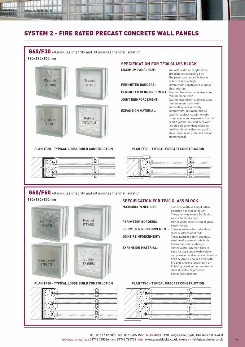
G60/F30 60 minutes integrity and 30 minutes thermal isolation.
Transparent(TF30T)
Bubble(TF30BU)
SPECIFICATION FOR TF30 GLASS BLOCKMAXIMUM PANEL SIZE: 9m2 with width or height either
direction not exceeding 6m. The panel was tested 14 blocks wide x 14 blocks high.
PERIMETER BORDERS: 50mm width constructed of glass block mortar.
PERIMETER REINFORCEMENT: Two number ø8mm stainless steel reinforcement rods.
JOINT REINFORCEMENT: Two number ø6mm stainless steel reinforcement rods both horizontally and vertically.
EXPANSION MATERIAL: 10mm width. Bitumen fibre to base for assistance with weight compression and expansion foam to head & jambs, caulked over with fire stop silicone (dependant on finishing detail, either encased in steel U profile or protected behind plasterboard).
SPECIFICATION FOR TF60 GLASS BLOCKMAXIMUM PANEL SIZE: 9m2 with width or height either
direction not exceeding 6m. The panel was tested 14 blocks wide x 14 blocks high.
PERIMETER BORDERS: 50mm width constructed of glass block mortar.
PERIMETER REINFORCEMENT: Three number ø8mm stainless steel reinforcement rods.
JOINT REINFORCEMENT: Three number ø6mm stainless steel reinforcement rods both horizontally and vertically.
EXPANSION MATERIAL: 10mm width. Bitumen fibre to base for assistance with weight compression and expansion foam to head & jambs, caulked over with fire stop silicone (dependant on finishing detail, either encased in steel U profile or protected behind plasterboard).
Frosted (TF60S)
Flemish(TF60N)
Transparent(TF60T)
Bubble(TF60BU)
G60/F60 60 minutes integrity and 60 minutes thermal isolation.
190x190x150mm
PLAN TF30 - TYPICAL LOOSE BUILD CONSTRUCTION PLAN TF30 - TYPICAL PRECAST CONSTRUCTION
PLAN TF60 - TYPICAL LOOSE BUILD CONSTRUCTION PLAN TF60 - TYPICAL PRECAST CONSTRUCTION
1109-Precast-A4-12pp 9/12/05 5:28 PM Page 9
FINISHINGWhere the precast panel meets the perimeter opening, the join has been decorativelyfinished by an architrave moulding.
For specific data sheets with reference to joint and border widths, steel reinforcementbar specification, and restraint/clamp detail, please contact GBT or visitwww.glassblocks.co.uk/datasheets or /firerating
SYSTEM 2 - FIRE RATED PRECAST CONCRETE WALL PANELS
10
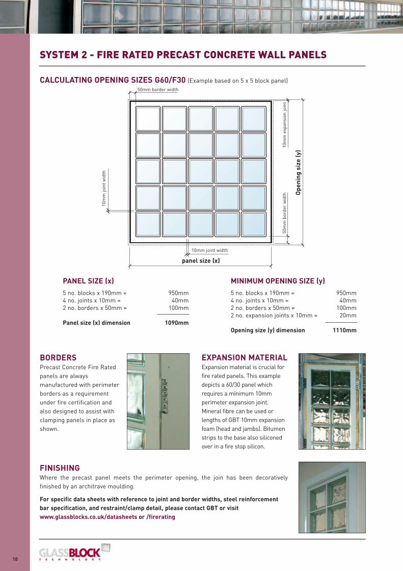
CALCULATING OPENING SIZES G60/F30 (Example based on 5 x 5 block panel)
PANEL SIZE (x)
5 no. blocks x 190mm = 950mm4 no. joints x 10mm = 40mm2 no. borders x 50mm = 100mm
Panel size (x) dimension 1090mm
panel size (x)
50m
m b
orde
r w
idth
10m
m e
xpan
sion
join
t
Ope
ning
siz
e (y
)
10mm joint width
10m
m jo
int
wid
th
50mm border width
MINIMUM OPENING SIZE (y)
5 no. blocks x 190mm = 950mm4 no. joints x 10mm = 40mm2 no. borders x 50mm = 100mm2 no. expansion joints x 10mm = 20mm
Opening size (y) dimension 1110mm
BORDERSPrecast Concrete Fire Ratedpanels are alwaysmanufactured with perimeterborders as a requirementunder fire certification andalso designed to assist withclamping panels in place asshown.
EXPANSION MATERIALExpansion material is crucial forfire rated panels. This exampledepicts a 60/30 panel whichrequires a minimum 10mmperimeter expansion joint. Mineral fibre can be used orlengths of GBT 10mm expansionfoam (head and jambs). Bitumenstrips to the base also siliconedover in a fire stop silicon.
1109-Precast-A4-12pp 9/12/05 5:28 PM Page 10
SYSTEM 2 - FIRE RATED PRECAST CONCRETE WALL PANELS
11
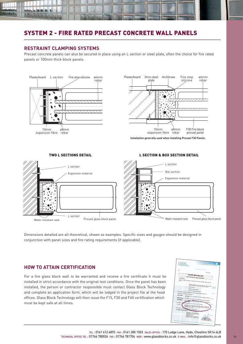
RESTRAINT CLAMPING SYSTEMSPrecast concrete panels can also be secured in place using an L section or steel plate, often the choice for fire ratedpanels or 100mm thick block panels.
TEL : 0161 612 6893 FAX : 0161 285 1503 SALES OFFICE : 170 Lodge Lane, Hyde, Cheshire SK14 4LB TECHNICAL OFFICE TEL : 01746 780026 FAX : 01746 781704 WEB : www.glassblocks.co.uk E-MAIL : [email protected]
L section
L sectionPrecast glass block panelWater resistant seal
Expansion material
Dimensions detailed are all theoretical, shown as examples. Specific sizes and gauges should be designed inconjunction with panel sizes and fire rating requirements (if applicable).
L SECTION & BOX SECTION DETAILTWO L SECTIONS DETAIL
Plasterboard Architrave Fire stopsilicone
ø6mm rebar
3mm steelplate
10mmexpansion fibre
ø8mm rebar
F30 Fire blockprecast panel
Installation generally used when installing Precast F30 Panels.
Box section
L section
Expansion material
Water resistant seal Precast glass block panel
HOW TO ATTAIN CERTIFICATION
For a fire glass block wall to be warranted and receive a fire certificate it must beinstalled in strict accordance with the original test conditions. Once the panel has beeninstalled, the person or contractor responsible must contact Glass Block Technologyand complete an application form, which will be lodged in the project file at the headoffices. Glass Block Technology will then issue the F15, F30 and F60 certification whichmust be kept safe at all times.
Fire stop siliconePlasterboard L section
10mmexpansion fibre
ø6mm rebar
ø8mm rebar
1109-Precast-A4-12pp 9/12/05 5:28 PM Page 11

TEL : 0161 612 6893 FAX : 0161 285 1503 SALES OFFICE : 170 Lodge Lane, Hyde, Cheshire SK14 4LB
TECHNICAL OFFICE TEL : 01746 780026 FAX : 01746 781704WEB : www.glassblocks.co.uk E-MAIL : [email protected]
INTRODUCTION TO PRECAST EASIFIX
INTRODUCTION TO PRECAST FLOORING
Two types of panel are available: Standard or interconnecting.
Precast Easifix panels should ideally be installed into a four sidedopening.
Precast Easifix is lighter in weight compared to Rods & Mortarconstruction.
USING PRECAST EASIFIX:
Precast Easifix is only recommended for internal use.
Precast Easifix is not fire rated.
Precast Easifix can only be used for straight applications.
Precast Easifix can only be manufactured using 80mm glass blocks.
Precast Easifix aluminium channel can be left exposed or thepanel can be framed by using a clip on plasterboard cover stripthat creates a clean line between plasterboard & glass blocks.Alternatively a decorative moulding.
Precast Easifix is an ideal product for bar fronts,counters, dividing walls, virtually any straight non-fireglass block panel.
Precast Floor Panels are produced with aminimum 30mm joint and 70mm border.
Glass Block Technology Ltd recommend that floorpanels are installed into a pre-prepared four sided opening with minimum bearings of 40mm and our Projects Department can offer adviceregarding loading requirements and fire ratingsalthough all calculations have to be qualified by astructural engineer*. *Structural engineer qualification not supplied by GBT Ltd.
Single units and connecting panels can bemanufactured. Loading information is available onrequest.
Their use doesn’t need to be restricted to justallowing natural light into basements. They can beincorporated into balconies, walkways, mezzaninefloors, bed decks, terraces and roof gardens.Combined with use of lighting, stunning aestheticaland practical architectural features can be created.
1109-Precast-A4-12pp 9/12/05 5:28 PM Page 12