anybus-s canopen fieldbus appendix & baud rate configuration ... parameter data ... er of this...
TRANSCRIPT

������������� ��������������������� ��������������������������������� ��
HMS Industrial NetworksMailing address: Box 4126, 300 04 Halmstad, SwedenVisiting address: Stationsgatan 37, Halmstad, Sweden
Connecting DevicesTM
E-mail: [email protected]: www.anybus.com
Fieldbus Appendix
Anybus®-S CANopenDoc.Id. SCM-1200-040ABS-COP-3 Rev. 2.10

Preface About This Document
How To Use This Document................................................................................................................. 1
Important User Information .................................................................................................................. 1
Related Documents.................................................................................................................................. 2
Document History ................................................................................................................................... 2
Conventions & Terminology.................................................................................................................. 3
Support....................................................................................................................................................... 4
Chapter 1 About the Anybus-S CANopen
General....................................................................................................................................................... 5
Features...................................................................................................................................................... 5
Fieldbus Conformance Notes ................................................................................................................ 5
Front View ................................................................................................................................................ 6
Chapter 2 Basic Operation
General Information................................................................................................................................ 7
Address & Baud Rate Configuration..................................................................................................... 7
Data Exchange.......................................................................................................................................... 8Parameter Data ............................................................................................................................... 8I/O Data........................................................................................................................................ 8
Network Reset Handling......................................................................................................................... 9Reset Node ...................................................................................................................................... 9Reset Communication....................................................................................................................... 9
Chapter 3 Object Dictionary Implementation
Standard Objects .................................................................................................................................... 10General.......................................................................................................................................... 10Object Entries................................................................................................................................ 10
Manufacturer Specific Objects ............................................................................................................. 12General.......................................................................................................................................... 12Input Buffer, Byte Access ............................................................................................................... 12Input Buffer, Word Access ............................................................................................................. 13Input Buffer, Double Word Access................................................................................................. 14Output Buffer, Byte Access............................................................................................................. 15Output Buffer, Word Access .......................................................................................................... 16Output Buffer, Double Word Access .............................................................................................. 17Anybus Status & Diagnostics ....................................................................................................... 18
Chapter 4 Mailbox Interface
Overview.................................................................................................................................................. 19
Fault Codes.............................................................................................................................................. 19
Table of Contents
Table of Contents

Table of Contents II
Initialisation............................................................................................................................................. 20Fieldbus Specific Initialisation (FB_INIT).................................................................................... 20
Identity Customization .......................................................................................................................... 21Set Product Code (SET_PRODUCT_CODE) .......................................................................... 22Set Product Info (SET_PRODUCT_INFO).............................................................................. 23Set Product Info All (SET_PROD_INFO_ALL) .................................................................... 25Set Hardware Revision (SET_HARDWARE_REV) .............................................................. 27
Miscellaneous .......................................................................................................................................... 28Set Offline Option (SET_OFFLINE_OPTION)...................................................................... 28Object Read (OBJECT_READ)................................................................................................. 29Object Write (OBJECT_WRITE) .............................................................................................. 31Emergency Message Indication (EMCY_MESSAGE) ................................................................ 33Object Mapping (OBJECT_REMAP) ........................................................................................ 35Set Version 3 COBID and Bootup Function (SET_VER_3_COBID_BOOTUP) ................. 37Disable access to the objects 1010h and 1011h (DISABLE_STORE_RESTORE) ................. 38Set amount of PDO’s (SET_PDO_AMOUNT)........................................................................ 39Get Notification Information (GET_NOTIFICATION_INFO).............................................. 40
Chapter 5 Fieldbus Specific Area
Memory Map........................................................................................................................................... 42
Appendix A Miscellaneous
Control Register Area ............................................................................................................................ 43
Appendix B Mechanical SpecificationStraight Switches & Connectors ..................................................................................................... 44Angled Switches & Connectors ...................................................................................................... 45
Appendix C Technical Specification
Electrical Specification .......................................................................................................................... 46Protective Earth (PE) Requirements .............................................................................................. 46Power Supply ................................................................................................................................. 46
Environmental Specification ................................................................................................................ 46
EMC Compliance (CE) ......................................................................................................................... 46
Appendix D Connectors
Fieldbus Interface................................................................................................................................... 47
Doc.Id. SCM-1200-040Anybus-S CANopenDoc.Rev. 2.10
Preface
P. About This Document
P.1 How To Use This Document
This document is intended to be used as a supplement to the Anybus-S Parallel Design Guide. The read-er of this document is expected to have basic knowledge in the CANopen fieldbus system, and commu-nication systems in general. Please consult the general Anybus-S Parallel Design Guide for further information about the Anybus-S platform.
P.2 Important User Information
The data and illustrations found in this document are not binding. We, HMS Industrial Networks AB, reserve the right to modify our products in line with our policy of continuous product development. The information in this document is subject to change without notice and should not be considered as a com-mitment by HMS Industrial Networks AB. HMS Industrial Networks AB assumes no responsibility for any errors that may appear in this document.
There are many applications of this product. Those responsible for the use of this device must ensure that all the necessary steps have been taken to verify that the application meets all performance and safe-ty requirements including any applicable laws, regulations, codes, and standards.
Anybus® is a registered trademark of HMS Industrial Networks AB. All other trademarks are the prop-erty of their respective holders.
The examples and illustrations in this document are included solely for illustrative purposes. Because of the many variables and requirements associated with any particular implementation, HMS cannot as-sume responsibility or liability for actual use based on these examples and illustrations.
Warning: This is a class A product. In a domestic environment this product may cause radio interfer-ence in which case the user may be required to take adequate measures.
ESD Note: This product contains ESD (Electrostatic Discharge) sensitive parts that may be damaged if ESD control procedures are not followed. Static control precautions are required when handling the product. Failure to observe this may cause damage to the product.
About This Document 2
Doc.Id. SCM-1200-040Anybus-S CANopenDoc.Rev. 2.10
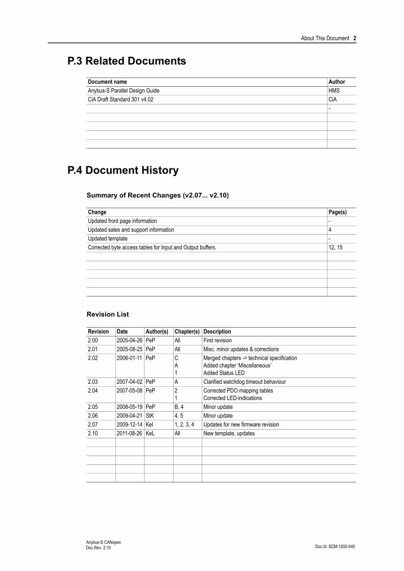
P.3 Related Documents
P.4 Document History
Summary of Recent Changes (v2.07... v2.10)
Revision List
Document name Author
Anybus-S Parallel Design Guide HMS
CiA Draft Standard 301 v4.02 CiA
-
Change Page(s)
Updated front page information -
Updated sales and support information 4
Updated template -
Corrected byte access tables for Input and Output buffers. 12, 15
Revision Date Author(s) Chapter(s) Description
2.00 2005-04-26 PeP All First revision
2.01 2005-08-25 PeP All Misc. minor updates & corrections
2.02 2006-01-11 PeP CA1
Merged chapters -> technical specificationAdded chapter ‘Miscellaneous’Added Status LED
2.03 2007-04-02 PeP A Clarified watchdog timeout behaviour
2.04 2007-05-08 PeP 21
Corrected PDO mapping tablesCorrected LED-indications
2.05 2008-05-19 PeP B, 4 Minor update
2.06 2009-04-21 StK 4, 5 Minor update
2.07 2009-12-14 Kel 1, 2, 3, 4 Updates for new firmware revision
2.10 2011-08-26 KeL All New template, updates

About This Document 3
Doc.Id. SCM-1200-040Anybus-S CANopenDoc.Rev. 2.10
P.5 Conventions & Terminology
The following conventions are used throughout this document:
• Numbered lists provide sequential steps
• Bulleted lists provide information, not procedural steps
• The term ‘module’ refers to the Anybus module
• The term ‘application’ refers to the device that hosts the Anybus module
• Hexadecimal values are written in the format NNNNh, where NNNN is the hexadecimal value.
• Commands instructs the module to perform certain task
• Functions are commands that returns data

About This Document 4
Doc.Id. SCM-1200-040Anybus-S CANopenDoc.Rev. 2.10
P.6 Sales and Support
Sales Support
HMS Sweden (Head Office)
E-mail: [email protected] E-mail: [email protected]
Phone: +46 (0) 35 - 17 29 56 Phone: +46 (0) 35 - 17 29 20
Fax: +46 (0) 35 - 17 29 09 Fax: +46 (0) 35 - 17 29 09
Online: www.anybus.com Online: www.anybus.com
HMS North America
E-mail: [email protected] E-mail: [email protected]
Phone: +1-312 - 829 - 0601 Phone: +1-312-829-0601
Toll Free: +1-888-8-Anybus Toll Free: +1-888-8-Anybus
Fax: +1-312-629-2869 Fax: +1-312-629-2869
Online: www.anybus.com Online: www.anybus.com
HMS Germany
E-mail: [email protected] E-mail: [email protected]
Phone: +49 (0) 721-96472-0 Phone: +49 (0) 721-96472-0
Fax: +49 (0) 721-96472-10 Fax: +49 (0) 721-96472-10
Online: www.anybus.de Online: www.anybus.de
HMS Japan
E-mail: [email protected] E-mail: [email protected]
Phone: +81 (0) 45-478-5340 Phone: +81 (0) 45-478-5340
Fax: +81 (0) 45-476-0315 Fax: +81 (0) 45-476-0315
Online: www.anybus.jp Online: www.anybus.jp
HMS China
E-mail: [email protected] E-mail: [email protected]
Phone: +86 (0) 10-8532-3183 Phone: +86 (0) 10-8532-3023
Fax: +86 (0) 10-8532-3209 Fax: +86 (0) 10-8532-3209
Online: www.anybus.cn Online: www.anybus.cn
HMS Italy
E-mail: [email protected] E-mail: [email protected]
Phone: +39 039 59662 27 Phone: +39 039 59662 27
Fax: +39 039 59662 31 Fax: +39 039 59662 31
Online: www.anybus.it Online: www.anybus.it
HMS France
E-mail: [email protected] E-mail: [email protected]
Phone: +33 (0) 3 68 368 034 Phone: +33 (0) 3 68 368 033
Fax: +33 (0) 3 68 368 031 Fax: +33 (0) 3 68 368 031
Online: www.anybus.fr Online: www.anybus.fr
HMS UK & Eire
E-mail: [email protected] E-mail: [email protected]
Phone: +44 (0) 1926 405599 Phone: +46 (0) 35 - 17 29 20
Fax: +44 (0) 1926 405522 Fax: +46 (0) 35 - 17 29 09
Online: www.anybus.co.uk Online: www.anybus.com
HMS Denmark
E-mail: [email protected] E-mail: [email protected]
Phone: +45 (0) 22 30 08 01 Phone: +46 (0) 35 - 17 29 20
Fax: +46 (0) 35 17 29 09 Fax: +46 (0) 35 - 17 29 09
Online: www.anybus.com Online: www.anybus.com
HMS India
E-mail: [email protected] E-mail: [email protected]
Phone: +91 (0) 20 40111201 Phone: +46 (0) 35 - 17 29 20
Fax: +91 (0) 20 40111105 Fax: +46 (0) 35 - 17 29 09
Online: www.anybus.com Online: www.anybus.com

Doc.Id. SCM-1200-040Anybus-S CANopenDoc.Rev. 2.10
Chapter 1
1. About the Anybus-S CANopen
1.1 General
The Anybus-S CANopen communication module provides instant CANopen connectivity via the pat-ented Anybus-S application interface. Any device that supports this standard can take advantage of the features provided by the module, allowing seamless network integration regardless of network type.
This product conforms to all aspects of the parallel application interface defined in the Anybus-S Parallel Design Guide, making it fully interchangeable with any other device following that specification. Gen-erally, very little network specific software support is needed, however in order to take advantage of ad-vanced network specific functionality, a certain degree of dedicated software support may be necessary.
1.2 Features
• DS301 v4.02 compliant
• Backwards compatible with DS301 v3
• Application interface fully backwards compatible with ABS-COP-1 & 2.
• Galvanically isolated bus electronics
• Supports all standard baud rates
• Customizable Identity Information
• EMCY support
• Object access via application interface
• Customizable PDO mapping
• Transmission types: PDO Sync, Change-of-state, Event based, RTR
• Network store/restore functionality
• Heartbeat & Node Guarding support
• Up to 2048+2048 bytes of slow I/O
• Up to 80 RPDO’s and 80 TPDO’s
1.3 Fieldbus Conformance Notes
• This product is pre-certified for network compliance. While this is done to ensure that the final product can be certified, it does not necessarily mean that the final product doesn’t need recerti-fication. Contact HMS for further information.
• To ensure interoperability, the device identity information must be customized. CiA (CAN in Automation) members should apply for a unique Vendor ID, non-members may contact HMS to obtain a custom Product ID. Note however that a unique Vendor ID is required when certi-fying the final product.
About the Anybus-S CANopen 6
Doc.Id. SCM-1200-040Anybus-S CANopenDoc.Rev. 2.10
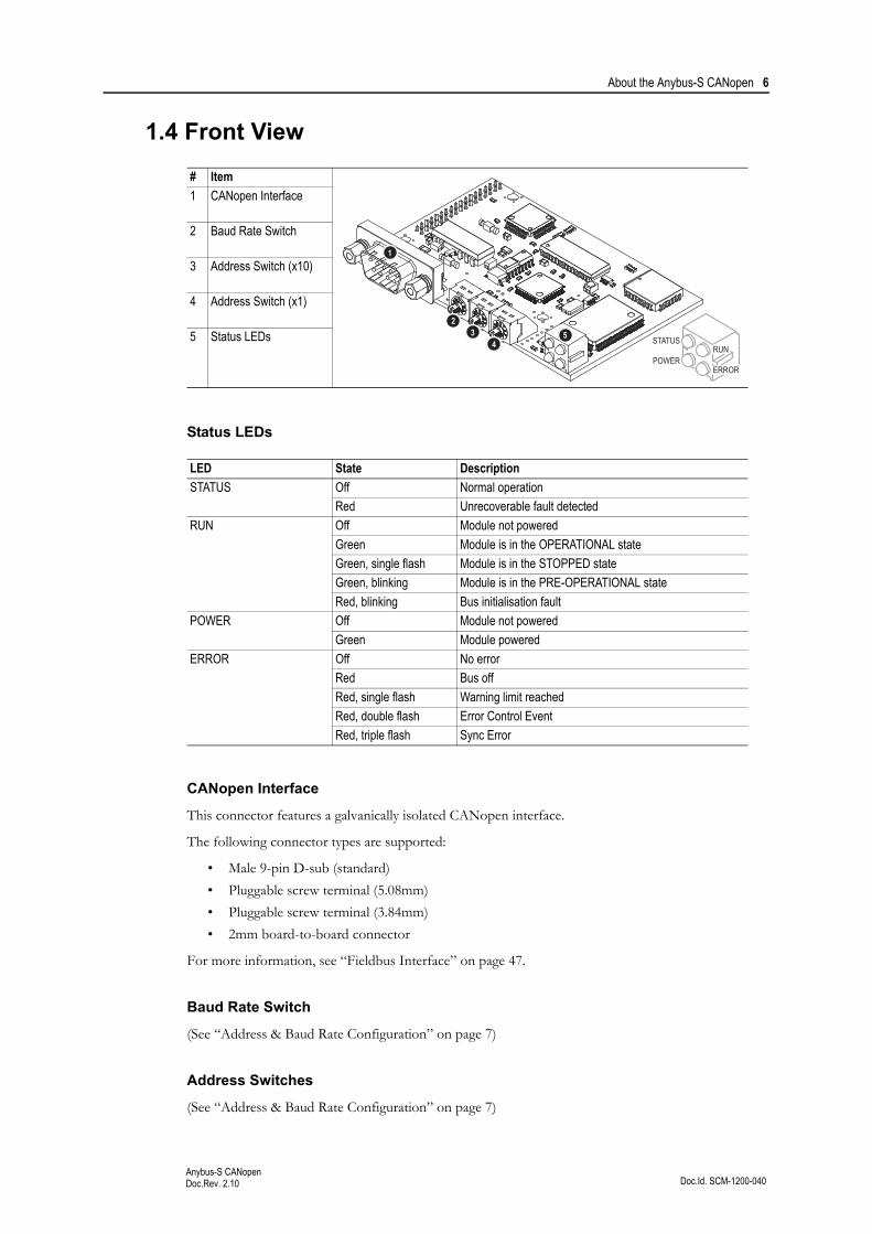
1.4 Front View
Status LEDs
CANopen Interface
This connector features a galvanically isolated CANopen interface.
The following connector types are supported:
• Male 9-pin D-sub (standard)
• Pluggable screw terminal (5.08mm)
• Pluggable screw terminal (3.84mm)
• 2mm board-to-board connector
For more information, see “Fieldbus Interface” on page 47.
Baud Rate Switch
(See “Address & Baud Rate Configuration” on page 7)
Address Switches
(See “Address & Baud Rate Configuration” on page 7)
# Item
1 CANopen Interface
2 Baud Rate Switch
3 Address Switch (x10)
4 Address Switch (x1)
5 Status LEDs
LED State Description
STATUS Off Normal operation
Red Unrecoverable fault detected
RUN Off Module not powered
Green Module is in the OPERATIONAL state
Green, single flash Module is in the STOPPED state
Green, blinking Module is in the PRE-OPERATIONAL state
Red, blinking Bus initialisation fault
POWER Off Module not powered
Green Module powered
ERROR Off No error
Red Bus off
Red, single flash Warning limit reached
Red, double flash Error Control Event
Red, triple flash Sync Error
POWER
STATUS
ERROR
RUN
1
2 3
4 5
Doc.Id. SCM-1200-040Anybus-S CANopenDoc.Rev. 2.10
Chapter 2
2. Basic Operation
2.1 General Information
Software Requirements
Generally, no additional network support code needs to be written in order to support the Anybus-S CANopen; however in order to take advantage of advanced network specific functionality, a certain de-gree of dedicated software support may be necessary.
For further information about the Anybus-S software interface, consult the general Anybus-S Parallel Design Guide.
Electronic Data Sheet (EDS)
Each device on CANopen is associated with an Electronic Data Sheet (a.k.a .EDS-file), which holds a description of the device and its functions. Most importantly, the file describes the object dictionary im-plementation in the module.
HMS supplies a generic .EDS-file which can be used as a basis for new implementations. Note however that this file must be adjusted to fit the end product.
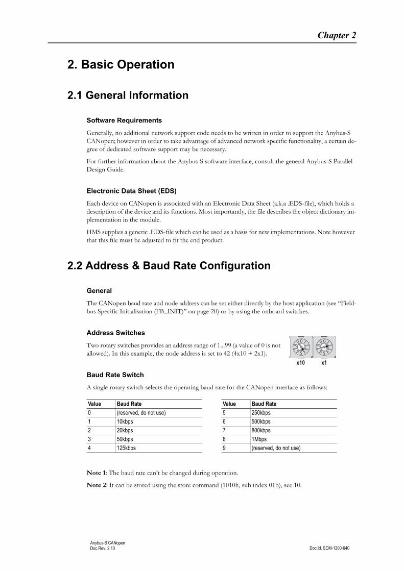
2.2 Address & Baud Rate Configuration
General
The CANopen baud rate and node address can be set either directly by the host application (see “Field-bus Specific Initialisation (FB_INIT)” on page 20) or by using the onboard switches.
Address Switches
Two rotary switches provides an address range of 1...99 (a value of 0 is not allowed). In this example, the node address is set to 42 (4x10 + 2x1).
Baud Rate Switch
A single rotary switch selects the operating baud rate for the CANopen interface as follows:
Note 1: The baud rate can’t be changed during operation.
Note 2: It can be stored using the store command (1010h, sub index 01h), see 10.
Value Baud Rate Value Baud Rate
0 (reserved, do not use) 5 250kbps
1 10kbps 6 500kbps
2 20kbps 7 800kbps
3 50kbps 8 1Mbps
4 125kbps 9 (reserved, do not use)
x10 x1
Basic Operation 8
Doc.Id. SCM-1200-040Anybus-S CANopenDoc.Rev. 2.10
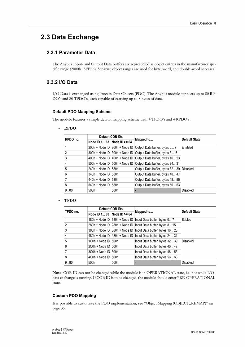
2.3 Data Exchange
2.3.1 Parameter Data
The Anybus Input- and Output Data buffers are represented as object entries in the manufacturer spe-cific range (2000h...5FFFh). Separate object ranges are used for byte, word, and double-word accesses.
2.3.2 I/O Data
I/O Data is exchanged using Process Data Objects (PDO). The Anybus module supports up to 80 RP-DO’s and 80 TPDO’s, each capable of carrying up to 8 bytes of data.
Default PDO Mapping Scheme
The module features a simple default mapping scheme with 4 TPDO’s and 4 RPDO’s.
• RPDO
• TPDO
Note: COB ID can not be changed while the module is in OPERATIONAL state, i.e. not while I/O data exchange is running. If COB ID is to be changed, the module should enter PRE-OPERATIONAL state.
Custom PDO Mapping
It is possible to customize the PDO implementation, see “Object Mapping (OBJECT_REMAP)” on page 35.
RPDO no.Default COB IDs
Mapped to... Default StateNode ID 1... 63 Node ID >= 64
1 200h + Node ID 200h + Node ID Output Data buffer, bytes 0... 7 Enabled
2 300h + Node ID 300h + Node ID Output Data buffer, bytes 8...15
3 400h + Node ID 400h + Node ID Output Data buffer, bytes 16... 23
4 500h + Node ID 500h + Node ID Output Data buffer, bytes 24... 31
5 240h + Node ID 580h Output Data buffer, bytes 32... 39 Disabled
6 340h + Node ID 580h Output Data buffer, bytes 40... 47
7 440h + Node ID 580h Output Data buffer, bytes 48... 55
8 540h + Node ID 580h Output Data buffer, bytes 56... 63
9...80 500h 500h - Disabled
TPDO no.Default COB IDs
Mapped to... Default StateNode ID 1... 63 Node ID >= 64
1 180h + Node ID 180h + Node ID Input Data buffer, bytes 0... 7 Eabled
2 280h + Node ID 280h + Node ID Input Data buffer, bytes 8... 15
3 380h + Node ID 380h + Node ID Input Data buffer, bytes 16... 23
4 480h + Node ID 480h + Node ID Input Data buffer, bytes 24... 31
5 1C0h + Node ID 500h Input Data buffer, bytes 32... 39 Disabled
6 2C0h + Node ID 500h Input Data buffer, bytes 40... 47
7 3C0h + Node ID 500h Input Data buffer, bytes 48... 55
8 4C0h + Node ID 500h Input Data buffer, bytes 56... 63
9...80 500h 500h - Disabled
Basic Operation 9
Doc.Id. SCM-1200-040Anybus-S CANopenDoc.Rev. 2.10
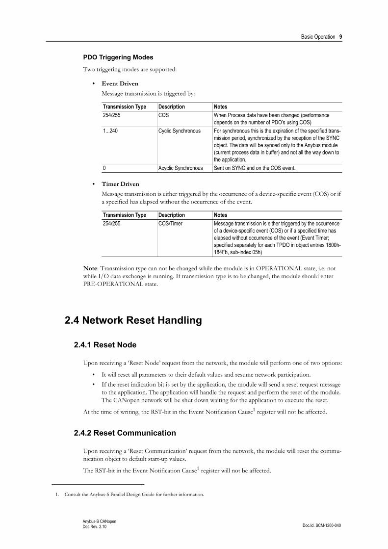
PDO Triggering Modes
Two triggering modes are supported:
• Event Driven
Message transmission is triggered by:
• Timer Driven
Message transmission is either triggered by the occurrence of a device-specific event (COS) or if a specified has elapsed without the occurrence of the event.
Note: Transmission type can not be changed while the module is in OPERATIONAL state, i.e. not while I/O data exchange is running. If transmission type is to be changed, the module should enter PRE-OPERATIONAL state.
2.4 Network Reset Handling
2.4.1 Reset Node
Upon receiving a ‘Reset Node’ request from the network, the module will perform one of two options:
• It will reset all parameters to their default values and resume network participation.
• If the reset indication bit is set by the application, the module will send a reset request message to the application. The application will handle the request and perform the reset of the module. The CANopen network will be shut down waiting for the application to execute the reset.
At the time of writing, the RST-bit in the Event Notification Cause1 register will not be affected.
2.4.2 Reset Communication
Upon receiving a ‘Reset Communication’ request from the network, the module will reset the commu-nication object to default start-up values.
The RST-bit in the Event Notification Cause1 register will not be affected.
Transmission Type Description Notes
254/255 COS When Process data have been changed (performance depends on the number of PDO’s using COS)
1...240 Cyclic Synchronous For synchronous this is the expiration of the specified trans-mission period, synchronized by the reception of the SYNC object. The data will be synced only to the Anybus module (current process data in buffer) and not all the way down to the application.
0 Acyclic Synchronous Sent on SYNC and on the COS event.
Transmission Type Description Notes
254/255 COS/Timer Message transmission is either triggered by the occurrence of a device-specific event (COS) or if a specified time has elapsed without occurrence of the event (Event Timer; specified separately for each TPDO in object entries 1800h-184Fh, sub-index 05h)
1. Consult the Anybus-S Parallel Design Guide for further information.
Doc.Id. SCM-1200-040Anybus-S CANopenDoc.Rev. 2.10
Chapter 3
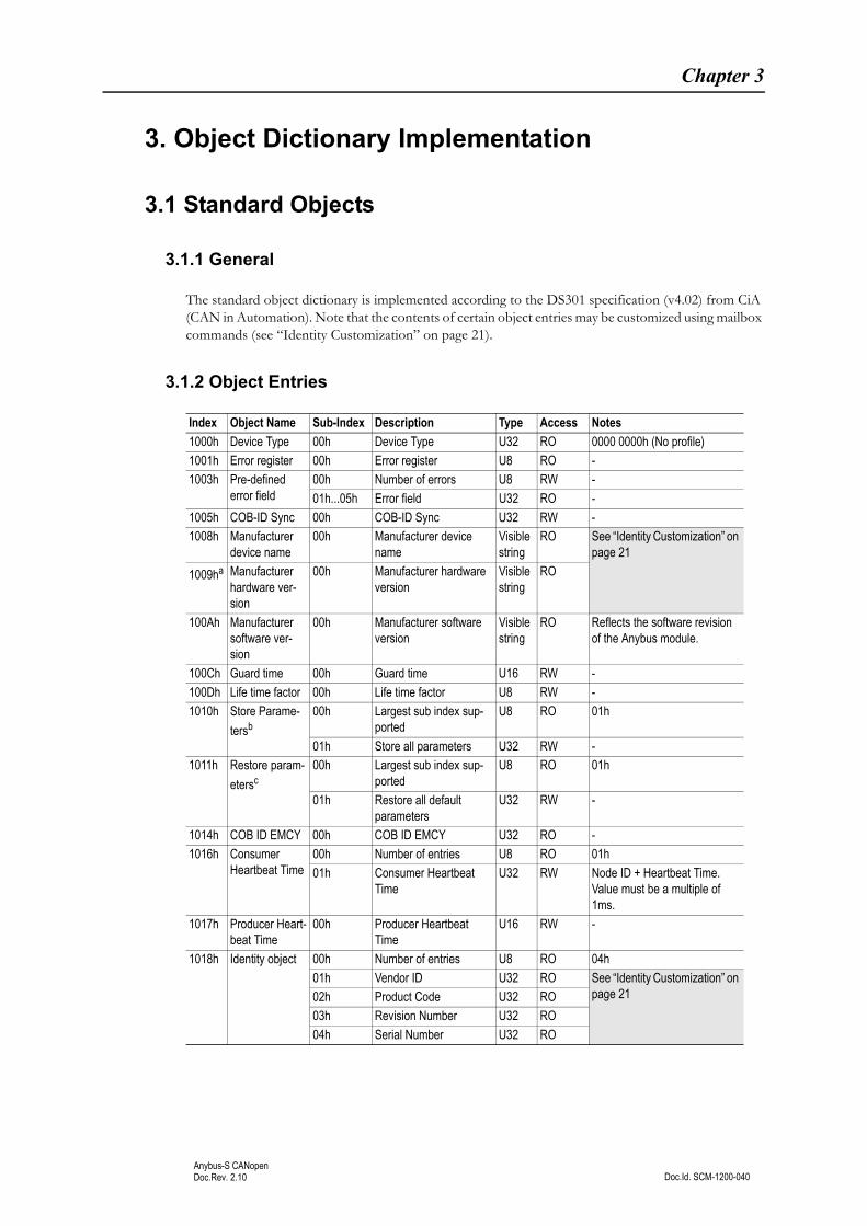
3. Object Dictionary Implementation
3.1 Standard Objects
3.1.1 General
The standard object dictionary is implemented according to the DS301 specification (v4.02) from CiA (CAN in Automation). Note that the contents of certain object entries may be customized using mailbox commands (see “Identity Customization” on page 21).
3.1.2 Object Entries
Index Object Name Sub-Index Description Type Access Notes
1000h Device Type 00h Device Type U32 RO 0000 0000h (No profile)
1001h Error register 00h Error register U8 RO -
1003h Pre-defined error field
00h Number of errors U8 RW -
01h...05h Error field U32 RO -
1005h COB-ID Sync 00h COB-ID Sync U32 RW -
1008h Manufacturer device name
00h Manufacturer device name
Visible string
RO See “Identity Customization” on page 21
1009ha Manufacturer hardware ver-sion
00h Manufacturer hardware version
Visible string
RO
100Ah Manufacturer software ver-sion
00h Manufacturer software version
Visible string
RO Reflects the software revision of the Anybus module.
100Ch Guard time 00h Guard time U16 RW -
100Dh Life time factor 00h Life time factor U8 RW -
1010h Store Parame-
tersb00h Largest sub index sup-
portedU8 RO 01h
01h Store all parameters U32 RW -
1011h Restore param-
etersc00h Largest sub index sup-
portedU8 RO 01h
01h Restore all default parameters
U32 RW -
1014h COB ID EMCY 00h COB ID EMCY U32 RO -
1016h Consumer Heartbeat Time
00h Number of entries U8 RO 01h
01h Consumer Heartbeat Time
U32 RW Node ID + Heartbeat Time. Value must be a multiple of 1ms.
1017h Producer Heart-beat Time
00h Producer Heartbeat Time
U16 RW -
1018h Identity object 00h Number of entries U8 RO 04h
01h Vendor ID U32 RO See “Identity Customization” on page 2102h Product Code U32 RO
03h Revision Number U32 RO
04h Serial Number U32 RO

Object Dictionary Implementation 11
Doc.Id. SCM-1200-040Anybus-S CANopenDoc.Rev. 2.10
1400h...144Fh
Receive PDO parameter
00h Largest sub-index sup-ported
U8 RO 02h
01h COB ID used by PDO U32 RW -
02h Transmission type U8 RW -
1600h...164Fh
Receive PDO mapping
00h No. of mapped applica-tion objects in PDO
U8 RW -
01h Mapped object #1 U32 RW -
02h Mapped object #2 U32 RW -
03h Mapped object #3 U32 RW -
04h Mapped object #4 U32 RW -
05h Mapped object #5 U32 RW -
06h Mapped object #6 U32 RW -
07h Mapped object #7 U32 RW -
08h Mapped object #8 U32 RW -
1800h...184Fh
Transmit PDO parameter
00h Largest sub-index sup-ported
U8 RO 05h
01h COB ID used by PDO U32 RW -
02h Transmission type U8 RW -
03h Inhibit time U16 RW -
05h Event Timer (ms) U16 RW -
1A00h...1A4Fh
Transmit PDO mapping
00h No. of mapped applica-tion objects in PDO
U8 RW -
01h Mapped object #1 U32 RW -
02h Mapped object #2 U32 RW -
03h Mapped object #3 U32 RW -
04h Mapped object #4 U32 RW -
05h Mapped object #5 U32 RW -
06h Mapped object #6 U32 RW -
07h Mapped object #7 U32 RW -
08h Mapped object #8 U32 RW -
a. This object is not enabled by default. For more information, see “Set Hardware Revision (SET_HARDWARE_REV)” on page 27.
b. Relevant only for communication parameters and for baud rate, that also is stored.c. When the restore command is issued, baud rate is restored to the current switch setting.
Index Object Name Sub-Index Description Type Access Notes
Object Dictionary Implementation 12
Doc.Id. SCM-1200-040Anybus-S CANopenDoc.Rev. 2.10
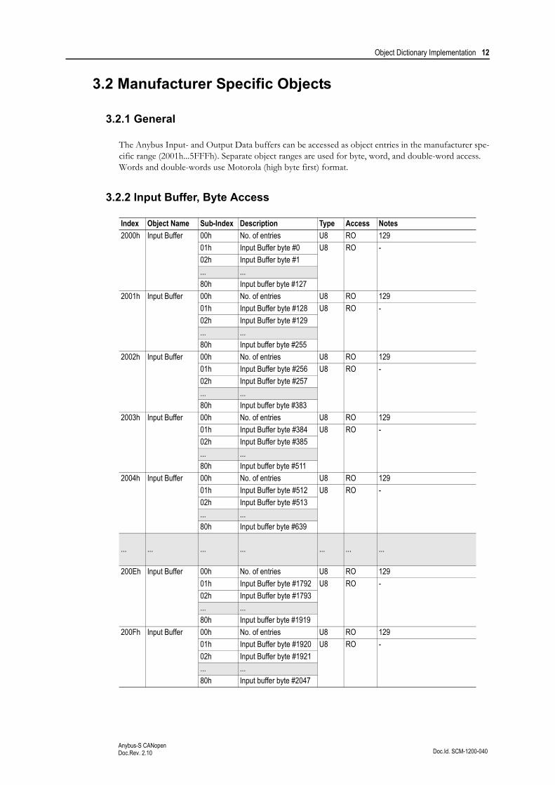
3.2 Manufacturer Specific Objects
3.2.1 General
The Anybus Input- and Output Data buffers can be accessed as object entries in the manufacturer spe-cific range (2001h...5FFFh). Separate object ranges are used for byte, word, and double-word access. Words and double-words use Motorola (high byte first) format.
3.2.2 Input Buffer, Byte Access
Index Object Name Sub-Index Description Type Access Notes
2000h Input Buffer 00h No. of entries U8 RO 129
01h Input Buffer byte #0 U8 RO -
02h Input Buffer byte #1
... ...
80h Input buffer byte #127
2001h Input Buffer 00h No. of entries U8 RO 129
01h Input Buffer byte #128 U8 RO -
02h Input Buffer byte #129
... ...
80h Input buffer byte #255
2002h Input Buffer 00h No. of entries U8 RO 129
01h Input Buffer byte #256 U8 RO -
02h Input Buffer byte #257
... ...
80h Input buffer byte #383
2003h Input Buffer 00h No. of entries U8 RO 129
01h Input Buffer byte #384 U8 RO -
02h Input Buffer byte #385
... ...
80h Input buffer byte #511
2004h Input Buffer 00h No. of entries U8 RO 129
01h Input Buffer byte #512 U8 RO -
02h Input Buffer byte #513
... ...
80h Input buffer byte #639
... ... ... ... ... ... ...
200Eh Input Buffer 00h No. of entries U8 RO 129
01h Input Buffer byte #1792 U8 RO -
02h Input Buffer byte #1793
... ...
80h Input buffer byte #1919
200Fh Input Buffer 00h No. of entries U8 RO 129
01h Input Buffer byte #1920 U8 RO -
02h Input Buffer byte #1921
... ...
80h Input buffer byte #2047

Object Dictionary Implementation 13
Doc.Id. SCM-1200-040Anybus-S CANopenDoc.Rev. 2.10
3.2.3 Input Buffer, Word Access
Index Object Name Sub-Index Description Type Access Notes
2020h Input Buffer 00h No. of entries U8 RO 65
01h Input Buffer word #0 U16 RO -
02h Input Buffer word #1
... ...
40h Input buffer word #63
2021h Input Buffer 00h No. of entries U8 RO 65
01h Input Buffer word #64 U16 RO -
02h Input Buffer word #65
... ...
40h Input buffer word #127
2022h Input Buffer 00h No. of entries U8 RO 65
01h Input Buffer word #128 U16 RO -
02h Input Buffer word #129
... ...
40h Input buffer word #191
2023h Input Buffer 00h No. of entries U8 RO 65
01h Input Buffer word #192 U16 RO -
02h Input Buffer word #193
... ...
40h Input buffer word #255
... ... ... ... ... ... ...
202Dh Input Buffer 00h No. of entries U8 RO 65
01h Input Buffer word #832 U16 RO -
02h Input Buffer word #833
... ...
40h Input buffer word #895
202Eh Input Buffer 00h No. of entries U8 RO 65
01h Input Buffer word #896 U16 RO -
02h Input Buffer word #897
... ...
40h Input buffer word #959
202Fh Input Buffer 00h No. of entries U8 RO 65
01h Input Buffer word #960 U16 RO -
02h Input Buffer word #961
... ...
40h Input buffer word #1023
Object Dictionary Implementation 14
Doc.Id. SCM-1200-040Anybus-S CANopenDoc.Rev. 2.10
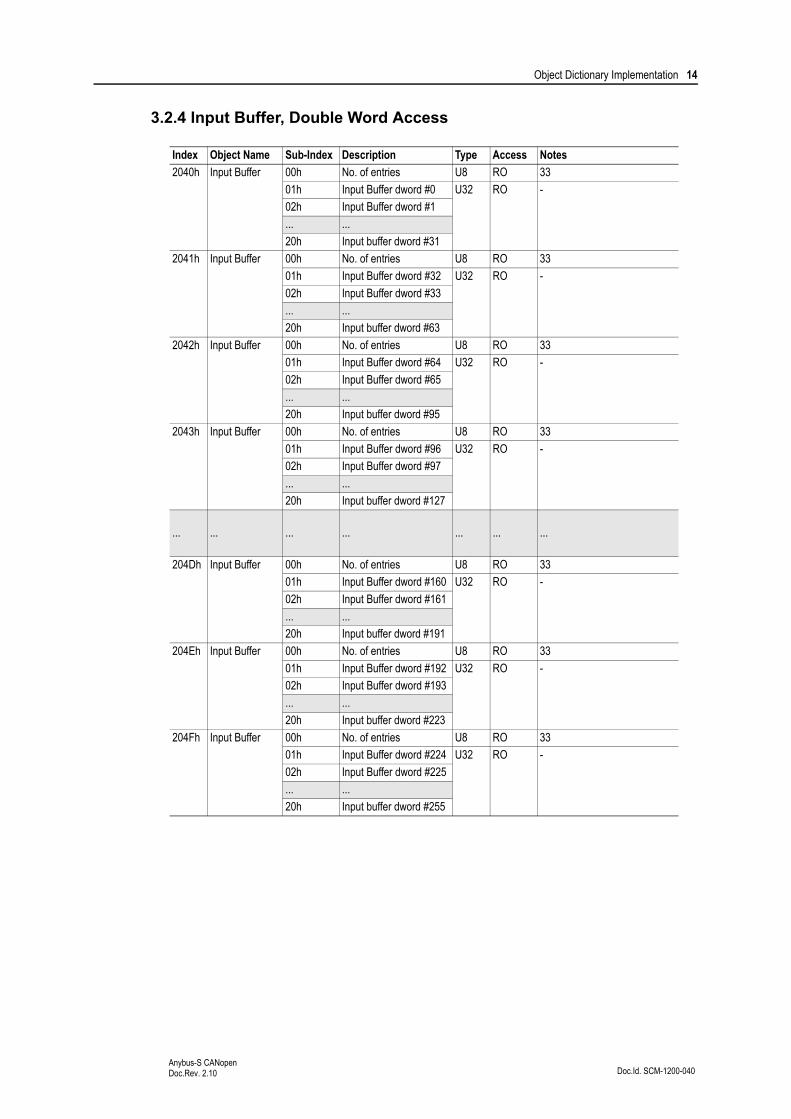
3.2.4 Input Buffer, Double Word Access
Index Object Name Sub-Index Description Type Access Notes
2040h Input Buffer 00h No. of entries U8 RO 33
01h Input Buffer dword #0 U32 RO -
02h Input Buffer dword #1
... ...
20h Input buffer dword #31
2041h Input Buffer 00h No. of entries U8 RO 33
01h Input Buffer dword #32 U32 RO -
02h Input Buffer dword #33
... ...
20h Input buffer dword #63
2042h Input Buffer 00h No. of entries U8 RO 33
01h Input Buffer dword #64 U32 RO -
02h Input Buffer dword #65
... ...
20h Input buffer dword #95
2043h Input Buffer 00h No. of entries U8 RO 33
01h Input Buffer dword #96 U32 RO -
02h Input Buffer dword #97
... ...
20h Input buffer dword #127
... ... ... ... ... ... ...
204Dh Input Buffer 00h No. of entries U8 RO 33
01h Input Buffer dword #160 U32 RO -
02h Input Buffer dword #161
... ...
20h Input buffer dword #191
204Eh Input Buffer 00h No. of entries U8 RO 33
01h Input Buffer dword #192 U32 RO -
02h Input Buffer dword #193
... ...
20h Input buffer dword #223
204Fh Input Buffer 00h No. of entries U8 RO 33
01h Input Buffer dword #224 U32 RO -
02h Input Buffer dword #225
... ...
20h Input buffer dword #255

Object Dictionary Implementation 15
Doc.Id. SCM-1200-040Anybus-S CANopenDoc.Rev. 2.10
3.2.5 Output Buffer, Byte Access
Index Object Name Sub-Index Description Type Access Notes
2100h Output Buffer 00h No. of entries U8 RO 129
01h Output Buffer byte #0 U8 R/W -
02h Output Buffer byte #1
... ...
80h Output buffer byte #127
2101h Output Buffer 00h No. of entries U8 RO 129
01h Output Buffer byte #128 U8 R/W -
02h Output Buffer byte #129
... ...
80h Output buffer byte #255
2102h Output Buffer 00h No. of entries U8 RO 129
01h Output Buffer byte #256 U8 R/W -
02h Output Buffer byte #257
... ...
80h Output buffer byte #383
2103h Output Buffer 00h No. of entries U8 RO 129
01h Output Buffer byte #384 U8 R/W -
02h Output Buffer byte #385
... ...
80h Output buffer byte #511
2104h Output Buffer 00h No. of entries U8 RO 129
01h Output Buffer byte #512 U8 R/W -
02h Output Buffer byte #513
... ...
80h Output buffer byte #630
... ... ... ... ... ... ...
210Dh Output Buffer 00h No. of entries U8 RO 129
01h Output Buffer byte #1664 U8 R/W -
02h Output Buffer byte #1665
... ...
80h Output buffer byte #1791
210Eh Output Buffer 00h No. of entries U8 RO 129
01h Output Buffer byte #1792 U8 R/W -
02h Output Buffer byte #1793
... ...
80h Output buffer byte #1919
210Fh Output Buffer 00h No. of entries U8 RO 129
01h Output Buffer byte #1920 U8 R/W -
02h Output Buffer byte #1921
... ...
80h Output buffer byte #2047
Object Dictionary Implementation 16
Doc.Id. SCM-1200-040Anybus-S CANopenDoc.Rev. 2.10
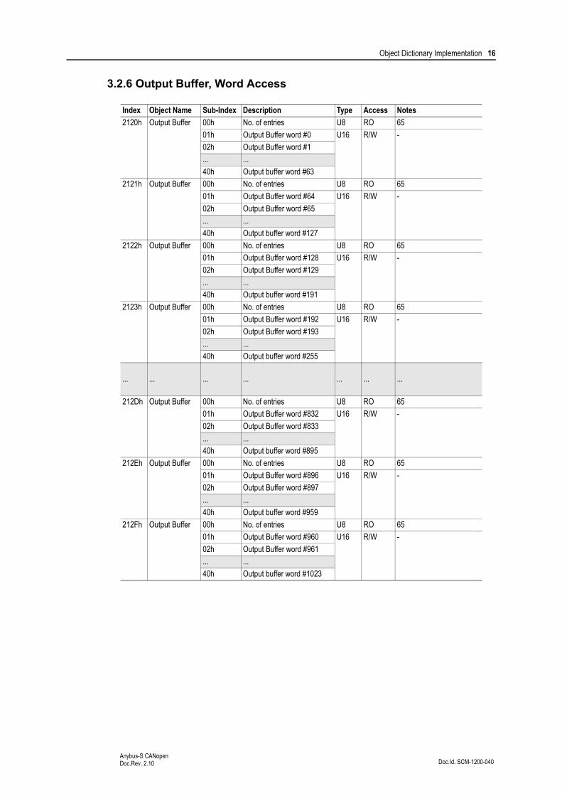
3.2.6 Output Buffer, Word Access
Index Object Name Sub-Index Description Type Access Notes
2120h Output Buffer 00h No. of entries U8 RO 65
01h Output Buffer word #0 U16 R/W -
02h Output Buffer word #1
... ...
40h Output buffer word #63
2121h Output Buffer 00h No. of entries U8 RO 65
01h Output Buffer word #64 U16 R/W -
02h Output Buffer word #65
... ...
40h Output buffer word #127
2122h Output Buffer 00h No. of entries U8 RO 65
01h Output Buffer word #128 U16 R/W -
02h Output Buffer word #129
... ...
40h Output buffer word #191
2123h Output Buffer 00h No. of entries U8 RO 65
01h Output Buffer word #192 U16 R/W -
02h Output Buffer word #193
... ...
40h Output buffer word #255
... ... ... ... ... ... ...
212Dh Output Buffer 00h No. of entries U8 RO 65
01h Output Buffer word #832 U16 R/W -
02h Output Buffer word #833
... ...
40h Output buffer word #895
212Eh Output Buffer 00h No. of entries U8 RO 65
01h Output Buffer word #896 U16 R/W -
02h Output Buffer word #897
... ...
40h Output buffer word #959
212Fh Output Buffer 00h No. of entries U8 RO 65
01h Output Buffer word #960 U16 R/W -
02h Output Buffer word #961
... ...
40h Output buffer word #1023

Object Dictionary Implementation 17
Doc.Id. SCM-1200-040Anybus-S CANopenDoc.Rev. 2.10
3.2.7 Output Buffer, Double Word Access
Index Object Name Sub-Index Description Type Access Notes
2140h Output Buffer 00h No. of entries U8 RO 33
01h Output Buffer dword #0 U32 R/W -
02h Output Buffer dword #1
... ...
20h Output buffer dword #31
2141h Output Buffer 00h No. of entries U8 RO 33
01h Output Buffer dword #32 U32 R/W -
02h Output Buffer dword #33
... ...
20h Output buffer dword #63
2142h Output Buffer 00h No. of entries U8 RO 33
01h Output Buffer dword #64 U32 R/W -
02h Output Buffer dword #65
... ...
20h Output buffer dword #95
2143h Output Buffer 00h No. of entries U8 RO 33
01h Output Buffer dword #96 U32 R/W -
02h Output Buffer dword #97
... ...
20h Output buffer dword #127
... ... ... ... ... ... ...
214Dh Output Buffer 00h No. of entries U8 RO 33
01h Output Buffer dword #160 U32 R/W -
02h Output Buffer dword #161
... ...
20h Output buffer dword #191
214Eh Output Buffer 00h No. of entries U8 RO 33
01h Output Buffer dword #192 U32 R/W -
02h Output Buffer dword #193
... ...
20h Output buffer dword #223
214Fh Output Buffer 00h No. of entries U8 RO 33
01h Output Buffer dword #224 U32 R/W -
02h Output Buffer dword #225
... ...
20h Output buffer dword #255

Object Dictionary Implementation 18
Doc.Id. SCM-1200-040Anybus-S CANopenDoc.Rev. 2.10
3.2.8 Anybus Status & Diagnostics
Index Object Name Sub-Index Type Access Notes
2200h Bus State Indicator 00h U8 RO Reflects the actual state of the bus.0: Bus initiating1: Error Active (bus is running, the node flags any errors found)2: Bus Off (node will be re-initiated, see object “Bus-off timeout” below)3: Error Passive (Bus is still running, but with a large amount of errors, the node does not flag any errors)
2205h Module State Indicator 00h U8 RO Reflects the state of the module on the network:0: Init-State/Reset state1: Init error2: Prepared3: Pre-operational4: Operational
2210h Module Serial Number 00h U32 RO These entries corresponds to the contents in the Control Register Area.(Consult the general Anybus-S Parallel Design Guide for further information).
2211h Vendor ID 00h U16 RO
2212h Module Status 00h U16 RO
2220h Event Notification Count 00h U16 RO
2221h Event Notification Cause 00h U16 RO
2222h Event Notification Source 00h U16 RO
2230h Watchdog Counter Input 00h U16 RO
2231h Watchdog Counter Output 00h U16 RO
2240h Input I/O Length 00h U16 RO
2241h Input DPRAM Length 00h U16 RO
2242h Total Input Length 00h U16 RO
2243h Output I/O Length 00h U16 RO
2244h Output DPRAM Length 00h U16 RO
2245h Total Output Length 00h U16 RO
2260h LED Status (1) 00h U8 RO
2261h LED Status (2) 00h U8 RO
2262h LED Status (3) 00h U8 RO
2263h LED Status (4) 00h U8 RO
2800h Bus-off timeout 00h U16 R/W Number of ms needed before the node re-initiates and enters pre-operational.(Default = 2000ms)

Doc.Id. SCM-1200-040Anybus-S CANopenDoc.Rev. 2.10
Chapter 4
4. Mailbox Interface
This chapter describes the fieldbus specific mailbox commands in the module. Consult the Anybus-S Design Guide for more information regarding the mailbox functionality.
4.1 Overview
4.2 Fault Codes
When a mailbox command cannot be processed, the Message Information register in the header of the response will indicate that an error occurred (consult the Anybus-S Design Guide for more informa-tion). If the error code is ‘Invalid Other’ (Fh), extended error information is available in the Fault Infor-mation register (Extended word 7 or 8, depending on the command).
This register holds a bit field where each bit indicates a particular error. This means that multiple faults may be indicated in a single message.
The structure of the Fault Information register is specified separately for each message.
Command Description Page
Fieldbus Specific Initialisation (FB_INIT) This command is used to initialise the module in fieldbus specific mode.
20
Set Product Code (SET_PRODUCT_CODE) These commands are used to customize the appearance of the module on the network.
22
Set Product Info (SET_PRODUCT_INFO) 23
Set Product Info All (SET_PROD_INFO_ALL) 25
Set Hardware Revision (SET_HARDWARE_REV) 27
Set Offline Option (SET_OFFLINE_OPTION) This command specified which event that should cause the module to consider the bus as off line.
28
Object Read (OBJECT_READ) These commands are used to access the CAN-open object library as if it was an actual request from the bus.
29
Object Write (OBJECT_WRITE) 31
Emergency Message Indication (EMCY_MESSAGE) This command is used to send an EMCY message on the bus.
33
Object Mapping (OBJECT_REMAP) This command controls the PDO mapping. 35
Set Version 3 COBID and Bootup Function (SET_VER_3_COBID_BOOTUP)
Enables DS301 version 3 operation 37
Disable access to the objects 1010h and 1011h (DISABLE_STORE_RESTORE)
Disable access to the object 1010h - Store param-eter and the object 1011h - Restore parameter
38
Set amount of PDO’s (SET_PDO_AMOUNT) Possible to define the amount of PDO’s that should be availble to use.
39
Get Notification Information (GET_NOTIFICATION_INFO)
Possible to get event notification from the module 40

Mailbox Interface 20
Doc.Id. SCM-1200-040Anybus-S CANopenDoc.Rev. 2.10
4.3 Initialisation
4.3.1 Fieldbus Specific Initialisation (FB_INIT)
Description
This command initialises the module in fieldbus specific mode, and can be used either in conjunction with - or completely replace - the Anybus Init command (note that this also affects the command- and response layout, most notably the location of the Fault Information register).
Note: This command may only be issued during initialisation.
Command and response layout (Anybus Init has been issued):
In this case, Anybus Init must be issued prior to this command.
• Fault Information
Command initiator Application
Command number 0001h
Extended Header data Fault information & Anybus Init Fault information
Message data Communication settings.
Response message -
Firmware Revision All
Command Expected response
Message ID (ID) (ID)
Message information 4002h 0002h
Command 0001h 0001h FB_INIT
Data size 0004h 0004h
Frame count 0001h 0001h
Frame number 0001h 0001h
Offset high 0000h 0000h
Offset low 0000h 0000h
Extended word 1 - -
Extended word 2 - -
Extended word 3 - -
Extended word 4 - -
Extended word 5 - -
Extended word 6 - -
Extended word 7 - -
Extended word 8 - Fault Information
Message data word 1 Node Address Node Address “Node Address” on page 21
Message data word 2 Baudrate Baudrate “Baudrate” on page 21
Bit Fault
0 Illegal node address value
1 Illegal baudrate value

Mailbox Interface 21
Doc.Id. SCM-1200-040Anybus-S CANopenDoc.Rev. 2.10
Command and response layout (Anybus Init has not been issued):
In this case, FB_INIT completely replaces the Anybus Init command.
• Anybus Init Fault Information
This value corresponds to the ‘Fault Information’ register returned by the module upon receiving the Anybus Init command. For more information, consult the general Anybus-S Parallel Design Guide.
• Node Address
Node address value. Valid settings range from 1...127.
• Baudrate
4.4 Identity Customization
Command Expected response
Message ID (ID) (ID)
Message information 4002h 0002h
Command 0001h 0001h FB_INIT
Data size 0016h 0016h
Frame count 0001h 0001h
Frame number 0001h 0001h
Offset high 0000h 0000h
Offset low 0000h 0000h
Extended word 1 - -
Extended word 2 - -
Extended word 3 - -
Extended word 4 - -
Extended word 5 - -
Extended word 6 - -
Extended word 7- Fault Information “Fault Information” on
page 20
Extended word 8 - Anybus Init Fault Information
Message data word 1 Input I/O Length Input I/O Length
Anybus Init parameters; Consult the Anybus-S Paral-lel Design Guide for further information
Message data word 2 Input DPRAM Length Input DPRAM Length
Message data word 3 Input Total Length Input Total Length
Message data word 4 Output I/O Length Output I/O Length
Message data word 5 Output DPRAM Length Output DPRAM Length
Message data word 6 Output Total Length Output Total Length
Message data word 7 Operation Mode Operation Mode
Message data word 8 Event Notification Config. Event Notification Config.
Message data word 9 Watchdog Timeout Value Watchdog Timeout Value
Message data word 10 Node Address Node Address
Message data word 11 Baudrate Baudrate
Value Baudrate Value Baudrate
1 10kbps 5 250kbps
2 20kbps 6 500kbps
3 50kbps 7 800kbps
4 125kbps 8 1Mbps

Mailbox Interface 22
Doc.Id. SCM-1200-040Anybus-S CANopenDoc.Rev. 2.10
4.4.1 Set Product Code (SET_PRODUCT_CODE)
This command is used to customize the Product Code in the Identity Object (CANopen object entry 1018h). This enables configuration tools etc. to identify the module as a specific implementation rather than a generic Anybus-S module. Please note that the .EDS-file must be updated accordingly.
Note: This command may only be issued during initialisation.
Command and response layout:
• Fault Information
(None)
• Product Code
4-byte Product Code.
Command initiator Application
Command number 0002h
Extended Header data Fault information
Message data Product code
Response message -
Firmware Revision 4.00 or higher
Command Expected response
Message ID (ID) (ID)
Message information 4002h 0002h
Command 0004h 0004h SET_PRODUCT_CODE
Data size 0004h 0004h
Frame count 0001h 0001h
Frame number 0001h 0001h
Offset high 0000h 0000h
Offset low 0000h 0000h
Extended word 1 - -
Extended word 2 - -
Extended word 3 - -
Extended word 4 - -
Extended word 5 - -
Extended word 6 - -
Extended word 7 - -
Extended word 8 - Fault Information
Message data byte 1 Product Code (high byte) Product Code (high byte)
Message data byte 2 Product Code (mid high byte) Product Code (mid high byte)
Message data byte 3 Product Code (mid low byte) Product Code (mid low byte)
Message data byte 4 Product Code (low byte) Product Code (low byte)

Mailbox Interface 23
Doc.Id. SCM-1200-040Anybus-S CANopenDoc.Rev. 2.10
4.4.2 Set Product Info (SET_PRODUCT_INFO)
This command customizes the following information:
• Vendor ID (Object entry 1018h, sub-index 01h)
• Product Code (Object entry 1018h, sub-index 02h)
• Manufacturer Device Name (Object entry 1008h)
This enables configuration tools etc. to identify the module as a specific implementation rather than a generic Anybus-S module. Please note that the .EDS-file must be updated accordingly.
Note: This command may only be issued during initialisation.
Command and response layout:
Command initiator Application
Command number 0003h
Extended Header data Fault information
Message data Misc. customization info
Response message -
Firmware Revision 4.00 or higher
Command Expected response
Message ID (ID) (ID)
Message information 4002h 0002h
Command 0003h 0003h SET_PRODUCT_INFO
Data size (size) (size)
Frame count 0001h 0001h
Frame number 0001h 0001h
Offset high 0000h 0000h
Offset low 0000h 0000h
Extended word 1 - -
Extended word 2 - -
Extended word 3 - -
Extended word 4 - -
Extended word 5 - -
Extended word 6 - -
Extended word 7 - -
Extended word 8 - Fault Information
Message data byte 1 Vendor ID (high byte) Vendor ID (high byte)
Message data byte 2 Vendor ID (mid high byte) Vendor ID (mid high byte)
Message data byte 1 Vendor ID (mid low byte) Vendor ID (mid low byte)
Message data byte 2 Vendor ID (low byte) Vendor ID (low byte)
Message data byte 3 Product Code (high byte) Product Code (high byte)
Message data byte 4 Product Code (mid high byte) Product Code (mid high byte)
Message data byte 3 Product Code (mid low byte) Product Code (mid low byte)
Message data byte 4 Product Code (low byte) Product Code (low byte)
Message data byte 5 Device Name Length Device Name Length String length (32 ch. max)
Message data byte 6 Device Name (1st char) Device Name (1st char) Manufacturer Device Name
Message data byte 7 Device Name (2nd char) Device Name (2nd char) ...
Message data byte 8 Device Name (3rd char) Device Name (3rd char) ...
... ... ... ...
Message data byte n Device Name (last char) Device Name (last char) ...

Mailbox Interface 24
Doc.Id. SCM-1200-040Anybus-S CANopenDoc.Rev. 2.10
• Fault Information
• Vendor ID
4-byte Vendor ID.
• Product Code
4-byte Product Code.
• Device Name Length
Length of the Manufacturer Device Name in bytes.
• Device Name
Manufacturer Device Name as ASCII string.
Bit Fault
7 Manufacturer Device Name too long (32 characters max.)

Mailbox Interface 25
Doc.Id. SCM-1200-040Anybus-S CANopenDoc.Rev. 2.10
4.4.3 Set Product Info All (SET_PROD_INFO_ALL)
This command is similar to SET_PRODUCT_INFO, except that it also specifies the Revision Number of the product. Please note that the .EDS-file must be updated accordingly.
Note: This command may only be issued during initialisation.
Command and response layout:
Command initiator Application
Command number 0004h
Extended Header data Fault information
Message data Misc. customization info
Response message -
Firmware Revision 4.00 or higher
Command Expected response
Message ID (ID) (ID)
Message information 4002h 0002h
Command 0004h 0004h SET_PROD_INFO_ALL
Data size (size) (size)
Frame count 0001h 0001h
Frame number 0001h 0001h
Offset high 0000h 0000h
Offset low 0000h 0000h
Extended word 1 - -
Extended word 2 - -
Extended word 3 - -
Extended word 4 - -
Extended word 5 - -
Extended word 6 - -
Extended word 7 - -
Extended word 8 - Fault Information
Message data byte 1 Vendor ID (high byte) Vendor ID (high byte)
Message data byte 2 Vendor ID (mid high byte) Vendor ID (mid high byte)
Message data byte 3 Vendor ID (mid low byte) Vendor ID (mid low byte)
Message data byte 4 Vendor ID (low byte) Vendor ID (low byte)
Message data byte 5 Product Code (high byte) Product Code (high byte)
Message data byte 6 Product Code (mid high byte) Product Code (mid high byte)
Message data byte 7 Product Code (mid low byte) Product Code (mid low byte)
Message data byte 8 Product Code (low byte) Product Code (low byte)
Message data byte 9 Revision No.(high byte) Revision No. (high byte)
Message data byte 10 Revision No. (mid high byte) Revision No. (mid high byte)
Message data byte 11 Revision No. (mid low byte) Revision No. (mid low byte)
Message data byte 12 Revision No. (low byte) Revision No. (low byte)
Message data byte 13 Device Name Length Device Name Length String length (32 ch. max)
Message data byte 14 Device Name (1st char) Device Name (1st char) Manufacturer Device Name
Message data byte 15 Device Name (2nd char) Device Name (2nd char) ...
Message data byte 16 Device Name (3rd char) Device Name (3rd char) ...
... ... ... ...
Message data byte n Device Name (last char) Device Name (last char) ...

Mailbox Interface 26
Doc.Id. SCM-1200-040Anybus-S CANopenDoc.Rev. 2.10
• Fault Information
• Vendor ID
4-byte Vendor ID.
• Product Code
4-byte Product Code.
• Revision No.
4-byte Revision Number.
• Device Name Length
Length of the Manufacturer Device Name in bytes.
• Device Name
Manufacturer Device Name as ASCII string.
Bit Fault
7 Manufacturer Device Name too long (32 characters max.)

Mailbox Interface 27
Doc.Id. SCM-1200-040Anybus-S CANopenDoc.Rev. 2.10
4.4.4 Set Hardware Revision (SET_HARDWARE_REV)
This command implements the Manufacturer Hardware Revision (1009h) entry in the CANopen object dictionary.
Note: This command may only be issued during initialisation.
Command and response layout:
• Fault Information
(None)
• Revision
4-byte Manufacturer Hardware Revision.
Command initiator Application
Command number 0006h
Extended Header data Fault information
Message data Manufacturer hardware revision value
Response message -
Firmware Revision 4.00 or higher
Command Expected response
Message ID (ID) (ID)
Message information 4002h 0002h
Command 0006h 0006h SET_HARDWARE_REV
Data size 0004h 0004h
Frame count 0001h 0001h
Frame number 0001h 0001h
Offset high 0000h 0000h
Offset low 0000h 0000h
Extended word 1 - -
Extended word 2 - -
Extended word 3 - -
Extended word 4 - -
Extended word 5 - -
Extended word 6 - -
Extended word 7 - -
Extended word 8 - Fault Information
Message data byte 1 Revision (high byte) Revision (high byte)
Message data byte 2 Revision (mid high byte) Revision (mid high byte)
Message data byte 3 Revision (mid low byte) Revision (mid low byte)
Message data byte 4 Revision (low byte) Revision (low byte)

Mailbox Interface 28
Doc.Id. SCM-1200-040Anybus-S CANopenDoc.Rev. 2.10
4.5 Miscellaneous
4.5.1 Set Offline Option (SET_OFFLINE_OPTION)
This command specifies which event that will cause the module to report the bus as offline.
Note: This command may only be issued during initialisation.
Command and response layout:
• Fault Information
• Offline Option
1: Bus error
2: Node Guarding or Heart Beat event
Command initiator Application
Command number 0007h
Extended Header data Fault information
Message data Offline option
Response message -
Firmware Revision 4.00 or higher
Command Expected response
Message ID (ID) (ID)
Message information 4002h 0002h
Command 0007h 0007h SET_OFFLINE_OPTION
Data size 0002h 0002h
Frame count 0001h 0001h
Frame number 0001h 0001h
Offset high 0000h 0000h
Offset low 0000h 0000h
Extended word 1 - -
Extended word 2 - -
Extended word 3 - -
Extended word 4 - -
Extended word 5 - -
Extended word 6 - -
Extended word 7 - -
Extended word 8 - Fault Information
Message data word 1 Offline Option Offline Option
Bit Fault
10 Illegal offline option value
Mailbox Interface 29
Doc.Id. SCM-1200-040Anybus-S CANopenDoc.Rev. 2.10
4.5.2 Object Read (OBJECT_READ)
This command returns the value of an entry in the CANopen object dictionary.
Command and response layout:
Command initiator Application
Command number 0010h
Extended Header data Object address details & fault information
Message data -
Response message Object data
Firmware Revision 4.10 or higher
Command Expected response
Message ID (ID) (ID)
Message information 4002h 0002h
Command 0010h 0010h OBJECT_READ
Data size 0000h (data size)
Frame count 0001h 0001h
Frame number 0001h 0001h
Offset high 0000h 0000h
Offset low 0000h 0000h
Extended word 1 Index Index
Extended word 2 Sub-Index Sub-Index
Extended word 3 0000h Length
Extended word 4 - -
Extended word 5 - -
Extended word 6 - -
Extended word 7 - -
Extended word 8 - Fault Information
Object Data
Response data
Mailbox Interface 30
Doc.Id. SCM-1200-040Anybus-S CANopenDoc.Rev. 2.10
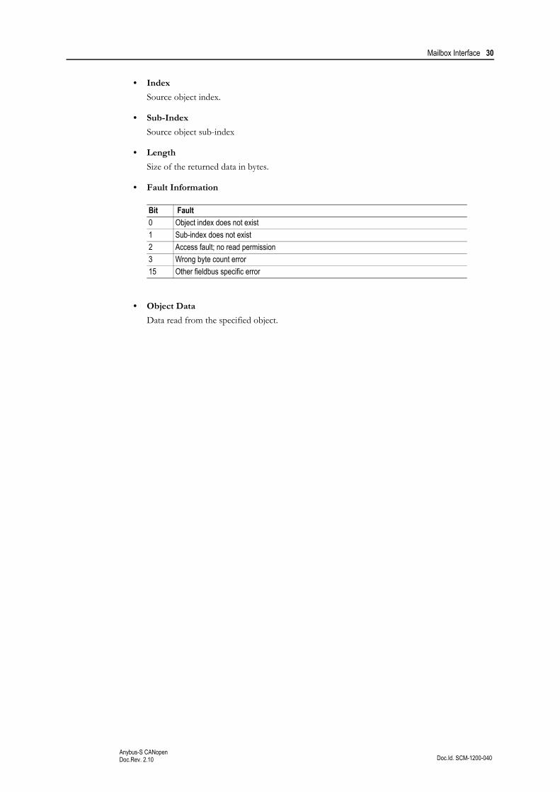
• Index
Source object index.
• Sub-Index
Source object sub-index
• Length
Size of the returned data in bytes.
• Fault Information
• Object Data
Data read from the specified object.
Bit Fault
0 Object index does not exist
1 Sub-index does not exist
2 Access fault; no read permission
3 Wrong byte count error
15 Other fieldbus specific error
Mailbox Interface 31
Doc.Id. SCM-1200-040Anybus-S CANopenDoc.Rev. 2.10
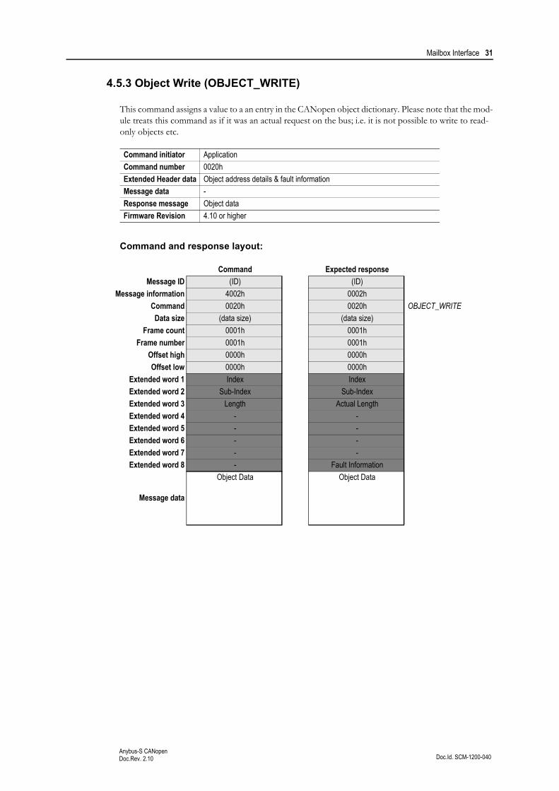
4.5.3 Object Write (OBJECT_WRITE)
This command assigns a value to a an entry in the CANopen object dictionary. Please note that the mod-ule treats this command as if it was an actual request on the bus; i.e. it is not possible to write to read-only objects etc.
Command and response layout:
Command initiator Application
Command number 0020h
Extended Header data Object address details & fault information
Message data -
Response message Object data
Firmware Revision 4.10 or higher
Command Expected response
Message ID (ID) (ID)
Message information 4002h 0002h
Command 0020h 0020h OBJECT_WRITE
Data size (data size) (data size)
Frame count 0001h 0001h
Frame number 0001h 0001h
Offset high 0000h 0000h
Offset low 0000h 0000h
Extended word 1 Index Index
Extended word 2 Sub-Index Sub-Index
Extended word 3 Length Actual Length
Extended word 4 - -
Extended word 5 - -
Extended word 6 - -
Extended word 7 - -
Extended word 8 - Fault Information
Message data
Object Data Object Data
Mailbox Interface 32
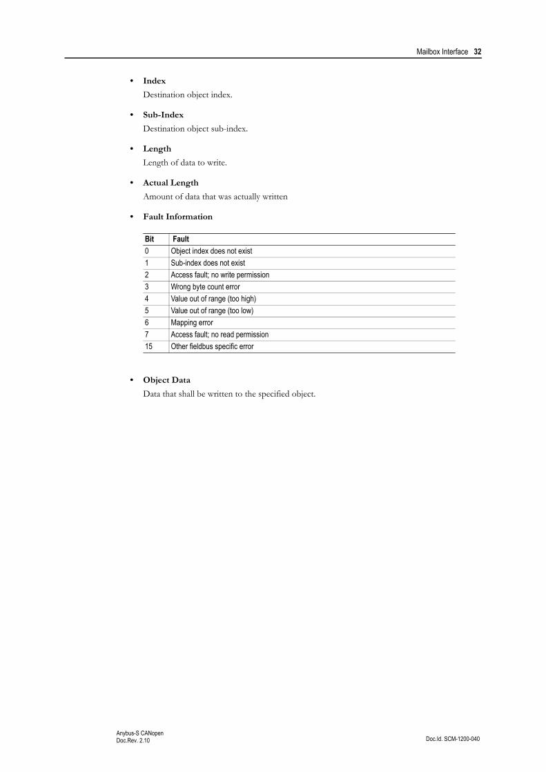
Doc.Id. SCM-1200-040Anybus-S CANopenDoc.Rev. 2.10
• Index
Destination object index.
• Sub-Index
Destination object sub-index.
• Length
Length of data to write.
• Actual Length
Amount of data that was actually written
• Fault Information
• Object Data
Data that shall be written to the specified object.
Bit Fault
0 Object index does not exist
1 Sub-index does not exist
2 Access fault; no write permission
3 Wrong byte count error
4 Value out of range (too high)
5 Value out of range (too low)
6 Mapping error
7 Access fault; no read permission
15 Other fieldbus specific error
Mailbox Interface 33
Doc.Id. SCM-1200-040Anybus-S CANopenDoc.Rev. 2.10
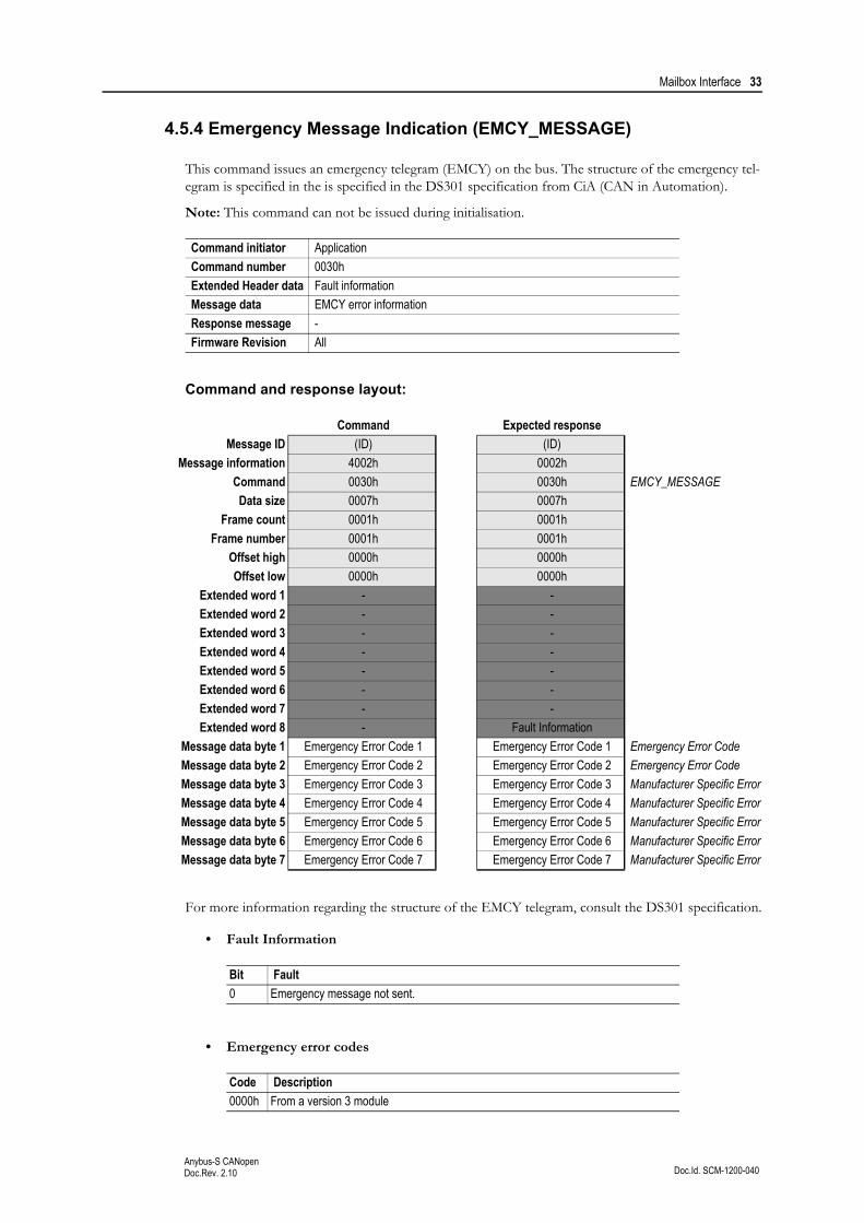
4.5.4 Emergency Message Indication (EMCY_MESSAGE)
This command issues an emergency telegram (EMCY) on the bus. The structure of the emergency tel-egram is specified in the is specified in the DS301 specification from CiA (CAN in Automation).
Note: This command can not be issued during initialisation.
Command and response layout:
For more information regarding the structure of the EMCY telegram, consult the DS301 specification.
• Fault Information
• Emergency error codes
Command initiator Application
Command number 0030h
Extended Header data Fault information
Message data EMCY error information
Response message -
Firmware Revision All
Command Expected response
Message ID (ID) (ID)
Message information 4002h 0002h
Command 0030h 0030h EMCY_MESSAGE
Data size 0007h 0007h
Frame count 0001h 0001h
Frame number 0001h 0001h
Offset high 0000h 0000h
Offset low 0000h 0000h
Extended word 1 - -
Extended word 2 - -
Extended word 3 - -
Extended word 4 - -
Extended word 5 - -
Extended word 6 - -
Extended word 7 - -
Extended word 8 - Fault Information
Message data byte 1 Emergency Error Code 1 Emergency Error Code 1 Emergency Error Code
Message data byte 2 Emergency Error Code 2 Emergency Error Code 2 Emergency Error Code
Message data byte 3 Emergency Error Code 3 Emergency Error Code 3 Manufacturer Specific Error
Message data byte 4 Emergency Error Code 4 Emergency Error Code 4 Manufacturer Specific Error
Message data byte 5 Emergency Error Code 5 Emergency Error Code 5 Manufacturer Specific Error
Message data byte 6 Emergency Error Code 6 Emergency Error Code 6 Manufacturer Specific Error
Message data byte 7 Emergency Error Code 7 Emergency Error Code 7 Manufacturer Specific Error
Bit Fault
0 Emergency message not sent.
Code Description
0000h From a version 3 module

Mailbox Interface 34
Doc.Id. SCM-1200-040Anybus-S CANopenDoc.Rev. 2.10
1080h Initialization failed
6100h Application stopped (watchdog timeout)
810h Transmit buffer overflow, receive buffer overflow or overrun condition
8120 Error passive condition
8140 Recover from busoff.
Code Description

Mailbox Interface 35
Doc.Id. SCM-1200-040Anybus-S CANopenDoc.Rev. 2.10
4.5.5 Object Mapping (OBJECT_REMAP)
This command customizes the PDO mapping, i.e. it specifies which locations in the Input- and Output Data Areas to exchange as Process Data Objects.
Note: This command may only be issued during initialisation.
Command and response layout:
Command initiator Application
Command number 0040h
Extended Header data Fault information
Message data PDO mapping information
Response message -
Firmware Revision 4.10 or higher
Command Expected response
Message ID (ID) (ID)
Message information 4002h 0002h
Command 0040h 0040h OBJECT_REMAP
Data size (size) (size)
Frame count 0001h 0001h
Frame number 0001h 0001h
Offset high 0000h 0000h
Offset low 0000h 0000h
Extended word 1 PDO Type PDO Type
Extended word 2 PDO Number PDO Number
Extended word 3 - -
Extended word 4 - -
Extended word 5 - -
Extended word 6 - -
Extended word 7 - -
Extended word 8 - Fault Information
Message data word 1 DPRAM Offset, byte #1 DPRAM Offset, byte #1
Message data word 2 DPRAM Offset, byte #2 DPRAM Offset, byte #2
Message data word 3 DPRAM Offset, byte #3 DPRAM Offset, byte #3
Message data word 4 DPRAM Offset, byte #4 DPRAM Offset, byte #4
... ... ...
Message data word n DPRAM Offset, byte #n DPRAM Offset, byte #n

Mailbox Interface 36
Doc.Id. SCM-1200-040Anybus-S CANopenDoc.Rev. 2.10
• PDO Type
0100h: TPDO0200h: RPDO
• PDO Number
This value specifies which PDO to map.
• Fault Information
• DPRAM Offset
This value specifies the location of the data in dual port memory.
- For TPDOs, this must correspond to a location within the Input Data Area(DPRAM offset 000h... 1FFh).
- For RPDOs, this must correspond to a location within the Output Data Area(DPRAM offset 200h... 3FFh).
Bit Fault
0 Illegal PDO specified in the request.
1 Direction error; illegal PDO type specified in the request.
2 Data error. Mapping problem.

Mailbox Interface 37
Doc.Id. SCM-1200-040Anybus-S CANopenDoc.Rev. 2.10
4.5.6 Set Version 3 COBID and Bootup Function (SET_VER_3_COBID_BOOTUP)
By default, the module operates according to DS301 version 4. This command makes it possible to downgrade the functionality of the COBID definition and Bootup functionality to DS301 version 3, en-abling the module to be used on a DS301 version 3 network without a CANopen configurator.
Note: This command may only be issued during initialisation.
Command and response layout:
Command initiator Application
Command number 0008h
Extended Header data Fault information
Message data -
Response message -
Firmware Revision 4.32 or higher
Command Expected response
Message ID (ID) (ID)
Message information 4002h 0002h
Command 0008h 0008h SET_VER_3_COBID
Data size 0000h 0000h
Frame count 0001h 0001h
Frame number 0001h 0001h
Offset high 0000h 0000h
Offset low 0000h 0000h
Extended word 1 - -
Extended word 2 - -
Extended word 3 - -
Extended word 4 - -
Extended word 5 - -
Extended word 6 - -
Extended word 7 - -
Extended word 8 - -
Mailbox Interface 38
Doc.Id. SCM-1200-040Anybus-S CANopenDoc.Rev. 2.10
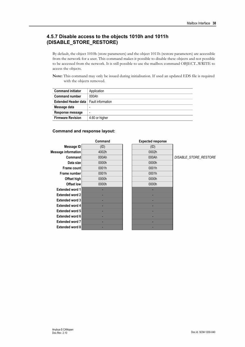
4.5.7 Disable access to the objects 1010h and 1011h (DISABLE_STORE_RESTORE)
By default, the object 1010h (store parameters) and the object 1011h (restore parameters) are accessible from the network for a user. This command makes it possible to disable these objects and not possible to be accessed from the network. It is still possible to use the mailbox command OBJECT_WRITE to access the objects.
Note: This command may only be issued during initialisation. If used an updated EDS file is required with the objects removed.
Command and response layout:
Command initiator Application
Command number 000Ah
Extended Header data Fault information
Message data -
Response message -
Firmware Revision 4.60 or higher
Command Expected response
Message ID (ID) (ID)
Message information 4002h 0002h
Command 000Ah 000Ah DISABLE_STORE_RESTORE
Data size 0000h 0000h
Frame count 0001h 0001h
Frame number 0001h 0001h
Offset high 0000h 0000h
Offset low 0000h 0000h
Extended word 1 - -
Extended word 2 - -
Extended word 3 - -
Extended word 4 - -
Extended word 5 - -
Extended word 6 - -
Extended word 7 - -
Extended word 8 - -

Mailbox Interface 39
Doc.Id. SCM-1200-040Anybus-S CANopenDoc.Rev. 2.10
4.5.8 Set amount of PDO’s (SET_PDO_AMOUNT)
This command makes it possible to define the amount of receive PDO’s and transmit PDO’s that should be available for a user, the value can be set from 1 to 80. If the command is not issued the default number of PDO’s (80) will be available in each direction.
Note: This command may only be issued during initialisation. If used it will require a new updated EDS file specifying the amount of PDO’s.
Command and response layout:
• Fault Information
If the command is rejected the maximum amount of PDO’s possible to use is returned.
Command initiator Application
Command number 0009h
Extended Header data Fault information
Message data Number of PDO’s
Response message Number of PDO’s
Firmware Revision 4.36 or higher
Command Expected response
Message ID (ID) (ID)
Message information 4002h 0002h
Command 0009h 0009h SET_PDO_AMOUNT
Data size 0004h 0004h
Frame count 0001h 0001h
Frame number 0001h 0001h
Offset high 0000h 0000h
Offset low 0000h 0000h
Extended word 1 - -
Extended word 2 - -
Extended word 3 - -
Extended word 4 - -
Extended word 5 - -
Extended word 6 - -
Extended word 7 - -
Extended word 8 - Fault Information
Message data word 1 Number of receive PDO’s Number of receive PDO’s
Message data word 2 Number of transmitt PDO’s Number of transmitt PDO’s
Mailbox Interface 40
Doc.Id. SCM-1200-040Anybus-S CANopenDoc.Rev. 2.10
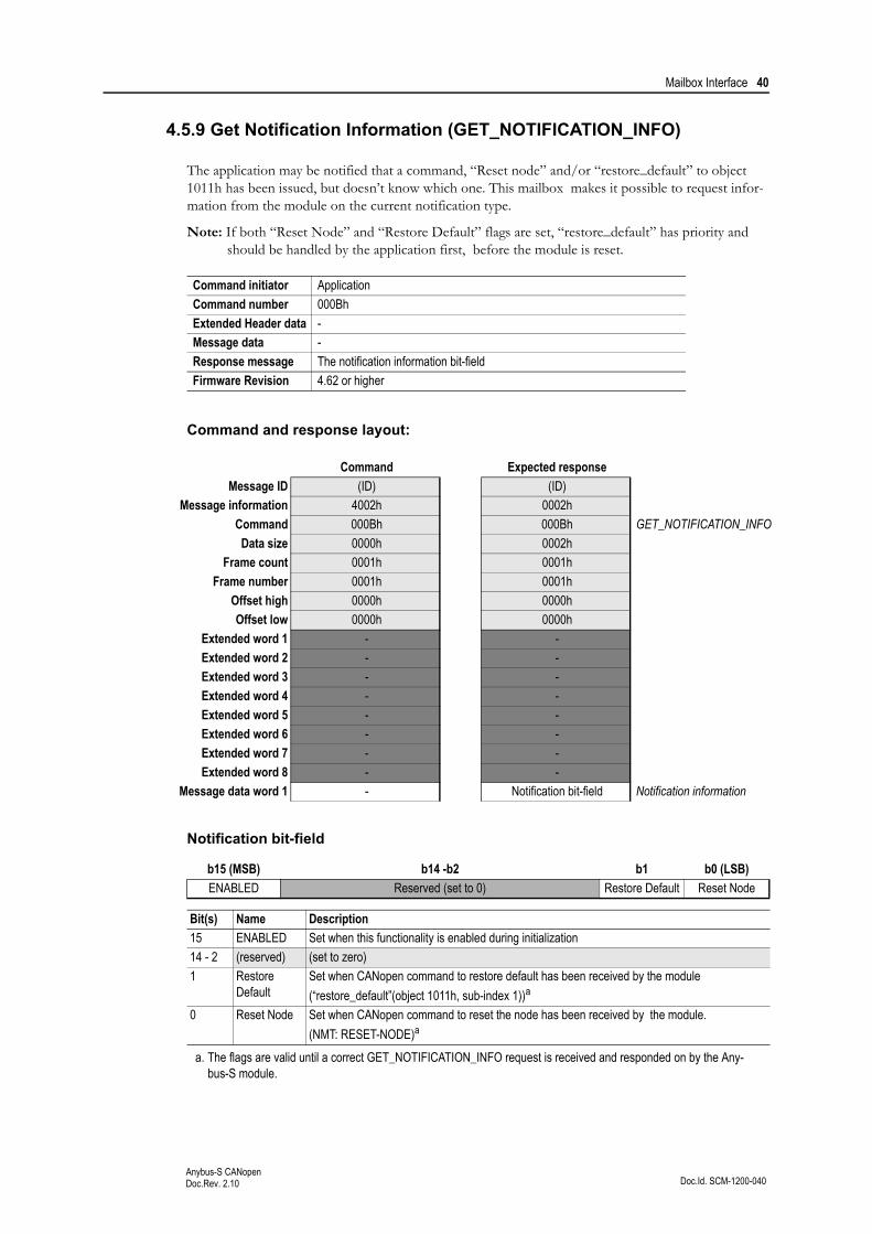
4.5.9 Get Notification Information (GET_NOTIFICATION_INFO)
The application may be notified that a command, “Reset node” and/or “restore_default” to object 1011h has been issued, but doesn’t know which one. This mailbox makes it possible to request infor-mation from the module on the current notification type.
Note: If both “Reset Node” and “Restore Default” flags are set, “restore_default” has priority and should be handled by the application first, before the module is reset.
Command and response layout:
Notification bit-field
Command initiator Application
Command number 000Bh
Extended Header data -
Message data -
Response message The notification information bit-field
Firmware Revision 4.62 or higher
Command Expected response
Message ID (ID) (ID)
Message information 4002h 0002h
Command 000Bh 000Bh GET_NOTIFICATION_INFO
Data size 0000h 0002h
Frame count 0001h 0001h
Frame number 0001h 0001h
Offset high 0000h 0000h
Offset low 0000h 0000h
Extended word 1 - -
Extended word 2 - -
Extended word 3 - -
Extended word 4 - -
Extended word 5 - -
Extended word 6 - -
Extended word 7 - -
Extended word 8 - -
Message data word 1 - Notification bit-field Notification information
b15 (MSB) b14 -b2 b1 b0 (LSB)
ENABLED Reserved (set to 0) Restore Default Reset Node
Bit(s) Name Description
15 ENABLED Set when this functionality is enabled during initialization
14 - 2 (reserved) (set to zero)
1 Restore Default
Set when CANopen command to restore default has been received by the module
(“restore_default”(object 1011h, sub-index 1))a
a. The flags are valid until a correct GET_NOTIFICATION_INFO request is received and responded on by the Any-bus-S module.
0 Reset Node Set when CANopen command to reset the node has been received by the module.
(NMT: RESET-NODE)a

Mailbox Interface 41
Doc.Id. SCM-1200-040Anybus-S CANopenDoc.Rev. 2.10

Doc.Id. SCM-1200-040Anybus-S CANopenDoc.Rev. 2.10
Chapter 5
5. Fieldbus Specific Area
5.1 Memory Map
• Node Address
This register contains the actual node address value (range: 1...127).
• Baudrate
This register contains the actual baudrate value as follows:
• Bus State Indicator
See object entry 2200h (“Anybus Status & Diagnostics” on page 18).
• Module State Indicator
See object entry 2205h (“Anybus Status & Diagnostics” on page 18).
• Error Control Indicator
This byte reflects if Node Guarding/Heartbeat is Disabled or Enabled
Note: Bit 0 is not set until first Node guarding is received from the Master.
Bit 1 is not set until first Heartbeat is received from the Slave/Master.
Address Register
640h Node Address
641h Baudrate
643h Bus State Indicator
644h Module State Indicator
645h Error Control Indicator
646h - 7BFh (reserved, do not use)
Value Baudrate Value Baudrate
1 10kbps 5 250kbps
2 20kbps 6 500kbps
3 50kbps 7 800kbps
4 125kbps 8 1Mbps
Bit Meaning
0 Node Guarding Enabled
1 Heartbeat Consumer Enabled
2 Heartbeat Producer Enabled
Doc.Id. SCM-1200-040Anybus-S CANopenDoc.Rev. 2.10
Appendix A
A. Miscellaneous
A.1 Control Register Area
Fieldbus Type
The fieldbus type value for this product is 0020h.
Module Type
The module type value for this product is 0101h (Anybus-S).
Watchdog Counter Input (7D2h... 7D3h)
If the application has enabled the Watchdog Counter Input and doesn’t update it properly, the module will issue an emergency message (Emergency Error Code 6100h, ‘Internal software error’) on the bus and cease all network participation. An internal error will be indicated on the Status LED.
Event Notification Cause/Source Registers
• ON/OFF Line Indication (FBON/FBOF)
See “Set Offline Option (SET_OFFLINE_OPTION)” on page 28.
• Network Reset Functionality (RST)
(not implemented)
Doc.Id. SCM-1200-040Anybus-S CANopenDoc.Rev. 2.10
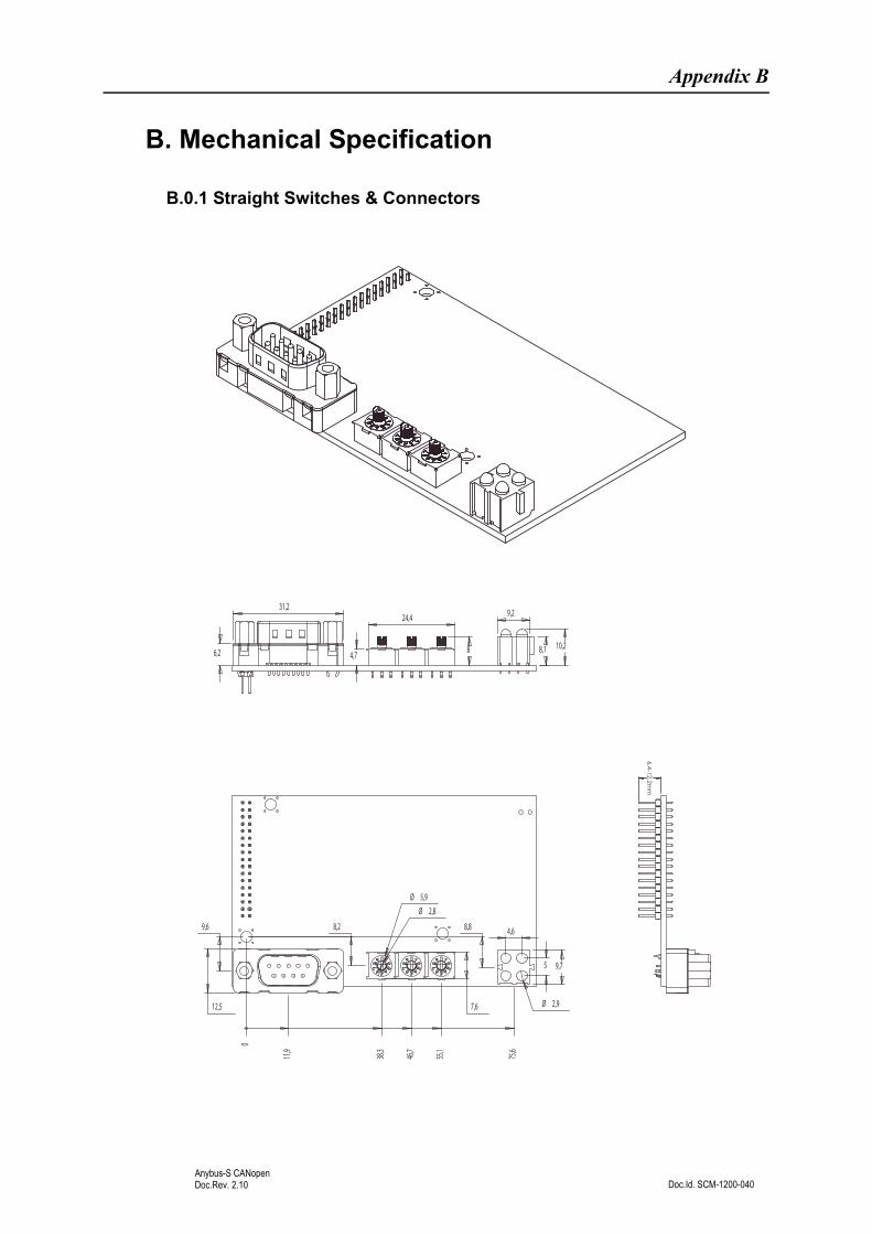
Appendix B
B. Mechanical Specification
B.0.1 Straight Switches & Connectors6,4-12,2m
m
31,224,4 9,2
6,2 4,78 8,1 10,2
0
11,9
46,7
55,1
75,6
38,3
9,6 8,2 8,8 4,6
5 9,7
12,5 7,6
Ø 5,9
Ø 2,8
Ø 2,9

Mechanical Specification 45
Doc.Id. SCM-1200-040Anybus-S CANopenDoc.Rev. 2.10
B.0.2 Angled Switches & Connectors
6,4-12,2mm
12,67,9 9,75,1
9,2
4,6
4
Ø 2,8
Ø 5,9
30,8
25,2
Ø 2,9
0
12
38,3
46,7
55,1
73,3
77,9
16,1 16,219,5
13,8 15,9

Doc.Id. SCM-1200-040Anybus-S CANopenDoc.Rev. 2.10
Appendix C
C. Technical Specification
C.1 Electrical Specification
C.1.1 Protective Earth (PE) Requirements
All Anybus-S/M modules features a cable shield filter designed according to each network standard. To be able to support this, the application must provide a connection to PE (Protective Earth) as described in the general Anybus-S Parallel Design Guide. HMS cannot guarantee proper EMC behaviour unless this requirement is fulfilled.
C.1.2 Power Supply
Supply Voltage
The module requires a regulated 5V power supply as specified in the Anybus-S Parallel Design Guide.
Power Consumption
The maximum power consumption is 140mA.
C.2 Environmental Specification
• Temperature
Test performed according to IEC-68-2-1 and IEC 68-2-2.
Operating:0 to 70°C(32 to 158°F)Storage:-25 to +85°C(-13 to 185°F)
• Humidity
The product is designed for a relative humidity of 5 to 95% non-condensing.
Test performed according to IEC 68-2-30.
C.3 EMC Compliance (CE)
The EMC pre-testing has been conducted according to the following standards:
• Emission: EN 50 081-2:1993
Tested perEN 55022 Class A: 1997
• Immunity: EN 61000-6-2: 1999
Tested perEN 61000-4-2:1995EN 61000-4-3:1996EN 61000-4-4:1995EN 61000-4-5:1995EN 61000-4-6:1996

Doc.Id. SCM-1200-040Anybus-S CANopenDoc.Rev. 2.10
Appendix D
D. Connectors
D.1 Fieldbus Interface
9-pin D-sub (Standard connector)
Screw Terminal
2mm Board to Board
Pin Signal
Housing CAN_SHLD
1 -
2 CAN_L
3 CAN_GND
4 -
5 CAN_SHLD
6 CAN_GND
7 CAN_H
8 -
9 (reserved)
Pin Signal
1 CAN_GND
2 CAN_L
3 CAN_SHLD
4 CAN_H
5 (reserved)
Pin Signal
1 CAN_SHLD
2 -
3 CAN_L
4 CAN_GND
5 CAN_H
6 CAN_GND
7 -
8 (reserved)
9 -
10 CAN_SHLD
5 1
69
Male
1 5
10
1
10
1