fieldbus system (si unit – canopen...
TRANSCRIPT

No.EX##-OMK0006-B
PRODUCT NAME
Fieldbus system
(SI unit – CANopen compatible)
MODEL / Series/ Product Number
EX250-SCA1A

-1-
No.EX##-OMK0006-B
Table of Contents
Safety Instructions 2 Model Indication and how to order 7 Names and Functions of products 7 Mounting and Installation 8
Installation 8 Wiring 9
Setting 14 Setting of Baud rate (Communication speed) 16 Overview object dictionary for communication object area 17 Overview object dictionary for manufacturer specific area 25 Overview object dictionary for device profile specific area 26 Error control services 31 Emergency object 32 Service data object (SDO) 33 Abort SDO transfer 33 Process data object (PDO) 34 Pre-defined connection set 35 Layer setting services (LSS) 35 Specification 44
Specifications 44 Dimensions 45

-2-
No.EX##-OMK0006-B
Safety Instructions These safety instructions are intended to prevent hazardous situations and/or equipment damage. These instructions indicate the level of potential hazard with the labels of "Caution", "Warning" or "Danger". They are all important notes for safety and must be followed in addition to International standards (ISO/IEC) ∗1) and other safety regulations.
∗1) ISO 4414: Pneumatic fluid power -- General rules relating to systems. ISO 4413: Hydraulic fluid power -- General rules relating to systems. IEC 60204-1: Safety of machinery -- Electrical equipment of machines. (Part 1: General requirements) ISO 10218-1992: Manipulating industrial robots -Safety. etc.
Caution : CAUTION indicates a hazard with a low level of risk which, if not avoided, could result in minor or moderate injury.
Warning : WARNING indicates a hazard with a medium level of risk which, if not avoided, could result in death or serious injury.
Danger : DANGER indicates a hazard with a high level of risk which, if not avoided, will result in death or serious injury.
Warning 1. The compatibility of the product is the responsibility of the person who designs the
equipment or decides its specifications. Since the product specified here is used under various operating conditions, its compatibility with specific equipment must be decided by the person who designs the equipment or decides its specifications based on necessary analysis and test results. The expected performance and safety assurance of the equipment will be the responsibility of the person who has determined its compatibility with the product. This person should also continuously review all specifications of the product referring to its latest catalog information, with a view to giving due consideration to any possibility of equipment failure when configuring the equipment.
2. Only personnel with appropriate training should operate machinery and equipment. The product specified here may become unsafe if handled incorrectly. The assembly, operation and maintenance of machines or equipment including our products must be performed by an operator who is appropriately trained and experienced.
3. Do not service or attempt to remove product and machinery/equipment until safety is confirmed. 1. The inspection and maintenance of machinery/equipment should only be performed after measures
to prevent falling or runaway of the driven objects have been confirmed. 2. When the product is to be removed, confirm that the safety measures as mentioned above are
implemented and the power from any appropriate source is cut, and read and understand the specific product precautions of all relevant products carefully.
3. Before machinery/equipment is restarted, take measures to prevent unexpected operation and malfunction.
4. Contact SMC beforehand and take special consideration of safety measures if the product is to be used in any of the following conditions.
1. Conditions and environments outside of the given specifications, or use outdoors or in a place exposed to direct sunlight.
2. Installation on equipment in conjunction with atomic energy, railways, air navigation, space, shipping, vehicles, military, medical treatment, combustion and recreation, or equipment in contact with food and beverages, emergency stop circuits, clutch and brake circuits in press applications, safety equipment or other applications unsuitable for the standard specifications described in the product catalog.
3. An application which could have negative effects on people, property, or animals requiring special safety analysis.
4. Use in an interlock circuit, which requires the provision of double interlock for possible failure by using a mechanical protective function, and periodical checks to confirm proper operation.

-3-
No.EX##-OMK0006-B
Caution The product is provided for use in manufacturing industries. The product herein described is basically provided for peaceful use in manufacturing industries. If considering using the product in other industries, consult SMC beforehand and exchange specifications or a contract if necessary. If anything is unclear, contact your nearest sales branch.
Limited warranty and Disclaimer/Compliance Requirements The product used is subject to the following "Limited warranty and Disclaimer" and "Compliance Requirements". Read and accept them before using the product.
Limited warranty and Disclaimer 1. The warranty period of the product is 1 year in service or 1.5 years after the product is delivered. ∗2)
Also, the product may have specified durability, running distance or replacement parts. Please consult your nearest sales branch.
2. For any failure or damage reported within the warranty period which is clearly our responsibility, a replacement product or necessary parts will be provided. This limited warranty applies only to our product independently, and not to any other damage incurred due to the failure of the product.
3. Prior to using SMC products, please read and understand the warranty terms and disclaimers noted in the specified catalog for the particular products.
∗2) Vacuum pads are excluded from this 1 year warranty. A vacuum pad is a consumable part, so it is warranted for a year after it is delivered. Also, even within the warranty period, the wear of a product due to the use of the vacuum pad or failure due to the deterioration of rubber material are not covered by the limited warranty.
Compliance Requirements
1. The use of SMC products with production equipment for the manufacture of weapons of mass destruction (WMD) or any other weapon is strictly prohibited.
2. The exports of SMC products or technology from one country to another are governed by the relevant security laws and regulation of the countries involved in the transaction. Prior to the shipment of a SMC product to another country, assure that all local rules governing that export are known and followed.
-4-
No.EX##-OMK0006-B
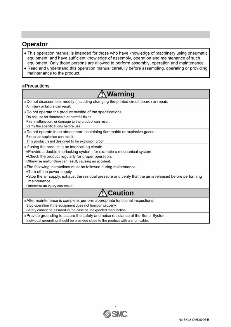
Operator
♦This operation manual is intended for those who have knowledge of machinery using pneumatic equipment, and have sufficient knowledge of assembly, operation and maintenance of such equipment. Only those persons are allowed to perform assembly, operation and maintenance.
♦Read and understand this operation manual carefully before assembling, operating or providing maintenance to the product.
Precautions
Warning Do not disassemble, modify (including changing the printed circuit board) or repair.
An injury or failure can result. Do not operate the product outside of the specifications.
Do not use for flammable or harmful fluids. Fire, malfunction, or damage to the product can result. Verify the specifications before use. Do not operate in an atmosphere containing flammable or explosive gases.
Fire or an explosion can result. This product is not designed to be explosion proof. If using the product in an interlocking circuit:
•Provide a double interlocking system, for example a mechanical system. •Check the product regularly for proper operation. Otherwise malfunction can result, causing an accident. The following instructions must be followed during maintenance:
•Turn off the power supply. •Stop the air supply, exhaust the residual pressure and verify that the air is released before performing maintenance.
Otherwise an injury can result.
Caution After maintenance is complete, perform appropriate functional inspections.
Stop operation if the equipment does not function properly. Safety cannot be assured in the case of unexpected malfunction. Provide grounding to assure the safety and noise resistance of the Serial System.
Individual grounding should be provided close to the product with a short cable.

-5-
No.EX##-OMK0006-B
NOTE Follow the instructions given below when designing, selecting and handling the product.
•The instructions on design and selection (installation, wiring, environment, adjustment, operation, maintenance, etc.) described below must also be followed. ∗Product specifications
•The direct current power supply to combine should be UL1310 Class 2 power supply when conformity to UL is necessary.
•The SI unit is a approved product only if they have a mark on the body. •Use the specified voltage.
Otherwise failure or malfunction can result. •Reserve a space for maintenance.
Allow sufficient space for maintenance when designing the system. •Do not remove any nameplates or labels.
This can lead to incorrect maintenance, or misreading of the operation manual, which could cause damage or malfunction to the product. It may also result in non-conformity to safety standards.
•Product handling ∗Installation
•Do not drop, hit or apply excessive shock to the fieldbus system. Otherwise damage to the product can result, causing malfunction.
•Tighten to the specified tightening torque. If the tightening torque is exceeded the mounting screws may be broken. IP67 protection cannot be guaranteed if the screws are not tightened to the specified torque.
•Never mount a product in a location that will be used as a foothold. The product may be damaged if excessive force is applied by stepping or climbing onto it.
∗Wiring •Avoid repeatedly bending or stretching the cables, or placing heavy load on them.
Repetitive bending stress or tensile stress can cause breakage of the cable. •Wire correctly.
Incorrect wiring can break the product. •Do not perform wiring while the power is on.
Otherwise damage to the fieldbus system and/or I/O device can result, causing malfunction. •Do not route wires and cables together with power or high voltage cables.
Otherwise the fieldbus system and/or I/O device can malfunction due to interference of noise and surge voltage from power and high voltage cables to the signal line. Route the wires (piping) of the fieldbus system and/or I/O device separately from power or high voltage cables.
•Confirm proper insulation of wiring. Poor insulation (interference from another circuit, poor insulation between terminals, etc.) can lead to excess voltage or current being applied to the product, causing damage.
•Take appropriate measures against noise, such as using a noise filter, when the fieldbus system is incorporated into equipment. Otherwise noise can cause malfunction.
•Separate the power line for output devices from the power line for control. Otherwise noise or induced surge voltage can cause malfunction.
-6-
No.EX##-OMK0006-B
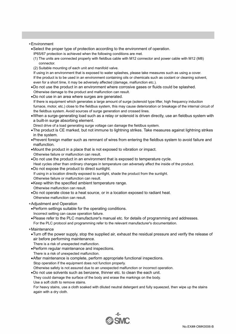
∗Environment
•Select the proper type of protection according to the environment of operation. IP65/67 protection is achieved when the following conditions are met. (1) The units are connected properly with fieldbus cable with M12 connector and power cable with M12 (M8)
connector. (2) Suitable mounting of each unit and manifold valve. If using in an environment that is exposed to water splashes, please take measures such as using a cover. If the product is to be used in an environment containing oils or chemicals such as coolant or cleaning solvent, even for a short time, it may be adversely affected (damage, malfunction etc.).
•Do not use the product in an environment where corrosive gases or fluids could be splashed. Otherwise damage to the product and malfunction can result.
•Do not use in an area where surges are generated. If there is equipment which generates a large amount of surge (solenoid type lifter, high frequency induction furnace, motor, etc.) close to the fieldbus system, this may cause deterioration or breakage of the internal circuit of the fieldbus system. Avoid sources of surge generation and crossed lines.
•When a surge-generating load such as a relay or solenoid is driven directly, use an fieldbus system with a built-in surge absorbing element. Direct drive of a load generating surge voltage can damage the fieldbus system.
•The product is CE marked, but not immune to lightning strikes. Take measures against lightning strikes in the system.
•Prevent foreign matter such as remnant of wires from entering the fieldbus system to avoid failure and malfunction.
•Mount the product in a place that is not exposed to vibration or impact. Otherwise failure or malfunction can result.
•Do not use the product in an environment that is exposed to temperature cycle. Heat cycles other than ordinary changes in temperature can adversely affect the inside of the product.
•Do not expose the product to direct sunlight. If using in a location directly exposed to sunlight, shade the product from the sunlight. Otherwise failure or malfunction can result.
•Keep within the specified ambient temperature range. Otherwise malfunction can result.
•Do not operate close to a heat source, or in a location exposed to radiant heat. Otherwise malfunction can result.
∗Adjustment and Operation •Perform settings suitable for the operating conditions.
Incorrect setting can cause operation failure. •Please refer to the PLC manufacturer's manual etc. for details of programming and addresses.
For the PLC protocol and programming refer to the relevant manufacturer's documentation.
∗Maintenance •Turn off the power supply, stop the supplied air, exhaust the residual pressure and verify the release of air before performing maintenance. There is a risk of unexpected malfunction.
•Perform regular maintenance and inspections. There is a risk of unexpected malfunction.
•After maintenance is complete, perform appropriate functional inspections. Stop operation if the equipment does not function properly. Otherwise safety is not assured due to an unexpected malfunction or incorrect operation.
•Do not use solvents such as benzene, thinner etc. to clean the each unit. They could damage the surface of the body and erase the markings on the body. Use a soft cloth to remove stains. For heavy stains, use a cloth soaked with diluted neutral detergent and fully squeezed, then wipe up the stains again with a dry cloth.

-7-
No.EX##-OMK0006-B
Model Indication and how to order
Names and Functions of products
No. Description Application 1 Communication connector Connect with CANopen communication line.∗1
2 Power supply connector Supplies power to the solenoid valve, the Output block, SI unit and the Input block. ∗1
3 Input block connector Connects the Input block. 4 Output block connector Connects the solenoid valve, Output block and etc. 5 Display LED display shows the SI unit status.∗2 6 Switch protective cover Set node ID and Baud rate by using the switches under the cover. ∗2 7 Ground terminal (FE) Used for grounding.
∗1: For wiring method, refer to subsection "Wiring" (page 9) in this operation manual. ∗2: For display and setting method, refer to subsection "Setting" (page 14) in this Technical Specification.

-8-
No.EX##-OMK0006-B
Mounting and Installation Installation Not having mounting hole, it can’t be set to BUS independently. Be sure to connect manifold to SI unit for setting. And if Input block is unnecessary, connect End plate directly to SI unit.
For example, the table below shows the size when manifold of VQC1000 series connected. Please refer to an individual catalog for the size when other manifolds are connected.
L 0 1 2 3 4 5 6 7 8 9 10 11 12 13 14 15 16
L1 45 55.5 66 76.5 87 97.5 108 118.5 129 139.5 150 160.5 171 181.5 192 202.5 213L2 89.8 110.8 131.8 152.8 173.8 194.8 215.8 236.8 257.8 278.8 299.8
Wiring (for power supply, communication and input) and piping are done on only one side. On the side, make a space for wiring and piping.
n_m

-9-
No.EX##-OMK0006-B
•Internal circuit
Wiring •Communication wiring
Communication connector M12 male 5 pins Pin No. Description Function
1 CAN_SHLD Shield 2 CAN_V+ Power supply + for CANopen 3 CAN_GND Power supply − for CANopen 4 CAN_H CAN_H bus line (dominant high)
5 CAN_L CAN_L bus line (dominant low) (Example of connection cable: M12 female 5pins cable with shield (according to ISO11898))
Baud rate and Bus cable length Relation Baud rate and Bus length are as follows.
Baud rate Max. bus cable length 1 Mbit/s 25 m
800 kbit/s 50 m 500 kbit/s 100 m 250 kbit/s 250 m 125 kbit/s 500 m 50 kbit/s 1000 m 20 kbit/s 2000 m 10 kbit/s 5000 m
-10-
No.EX##-OMK0006-B
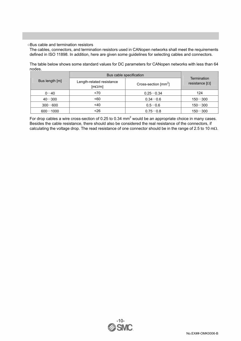
Bus cable and termination resistors The cables, connectors, and termination resistors used in CANopen networks shall meet the requirements defined in ISO 11898. In addition, here are given some guidelines for selecting cables and connectors.
The table below shows some standard values for DC parameters for CANopen networks with less than 64 nodes.
Bus cable specification Bus length [m] Length-related resistance
[mΩ/m] Cross-section [mm2]
Termination resistance [Ω]
0…40 <70 0.25…0.34 124
40…300 <60 0.34…0.6 150…300 300…600 <40 0.5…0.6 150…300
600…1000 <26 0.75…0.8 150…300
For drop cables a wire cross-section of 0.25 to 0.34 mm2 would be an appropriate choice in many cases. Besides the cable resistance, there should also be considered the real resistance of the connectors, if calculating the voltage drop. The read resistance of one connector should be in the range of 2.5 to 10 mΩ.

-11-
No.EX##-OMK0006-B
•Power supply wiring Power supply connector M12 male 5pins reverse key type
Pin No. Description Function 1 SV 24 V +24 V for solenoid valve. 2 SV 0 V 0 V for solenoid valve 3 SW 24 V +24 V for input block 4 SW 0 V 0 V for input block
5 FE Functional earth (Example of connection cable: EX9-AC050-1 etc.)
Power supply line inside the unit has individual power supplies for solenoid valve actuation (SV power supply) and for Input block (SW power supply). Supply 24 VDC for each of them. Either single or dual power supply is available.
∗ : In case of single power supply, pay attention to the range of each supply voltage.

-12-
No.EX##-OMK0006-B
Power for sensor is supplied to sensor connected with Input block. Select sensor concerning voltage drop up to maximum 1 V inside the unit at this moment. If sensor requires 24 V, it is necessary to lower power supply voltage for sensor slightly or secure power supply for sensor separately without going through SI unit so that sensor input voltage can be 24 V with actual loading (allowable voltage of power supply: 19.2 V to 28.8 V).
Terminator
Connect the ground terminal to ground. Resistance to ground should be 100 ohms or less.

-13-
No.EX##-OMK0006-B
•Maintenance Addition of Input Block ・Remove screws from End Plate. ・Mount attached tie rod. ・Connect additional Input Block. ・Connect End Plate and tighten removed screws by specified tightening torque. (0.6 Nm)
Exchange of SI unit ・Remove screws from End Plate and release connection of each unit. ・Replace old SI unit with new one. (Tie rod does not need to be removed.) ・Connect End Plate and tighten removed screws by specified tightening torque. (0.6 Nm) Caution for maintenance (1) Be sure to turn-off all power supplies. (2) Be sure that there is no foreign object in any of units. (3) Be sure that gasket is lined properly. (4) Be sure that tightening torque is according to specification.
If these items are not kept, it may lead to the breakage of substrate or intrusion of liquid or dust into the units.
Assembly and disconnection of unit

-14-
No.EX##-OMK0006-B
Setting •LED display
Indication Contents PWR(V) Green Light Illuminates when power for solenoid valves is supplied.
PWR Green Light Illuminates when power for CANopen line is supplied. Green Light Illuminates when SI unit is in the Operational state. Green Light (blinking) SI unit is in the Pre-Operational state. Green Light (single flash) Single flash when SI unit is in Stopped state. Red Light (single flash) Single flash when CAN controller error occurs. Red Light (double flash) Double flash when Error Control Event occurs.
Green / Red Light (flickering) Flickering when SI unit is in Configuration mode. (LSS services)
CAN
Red Light SI unit is in “Bus OFF” state.

-15-
No.EX##-OMK0006-B
∗: LED Indication of SI unit is based on CANopen Specification (CANopen Spec.DR-303-3). Refer to DR-303-3 Indicator Specification for details.
Switch setting Before setting of Node-ID by DIP switch, turn “OFF” power supply to the SI unit.
-16-
No.EX##-OMK0006-B
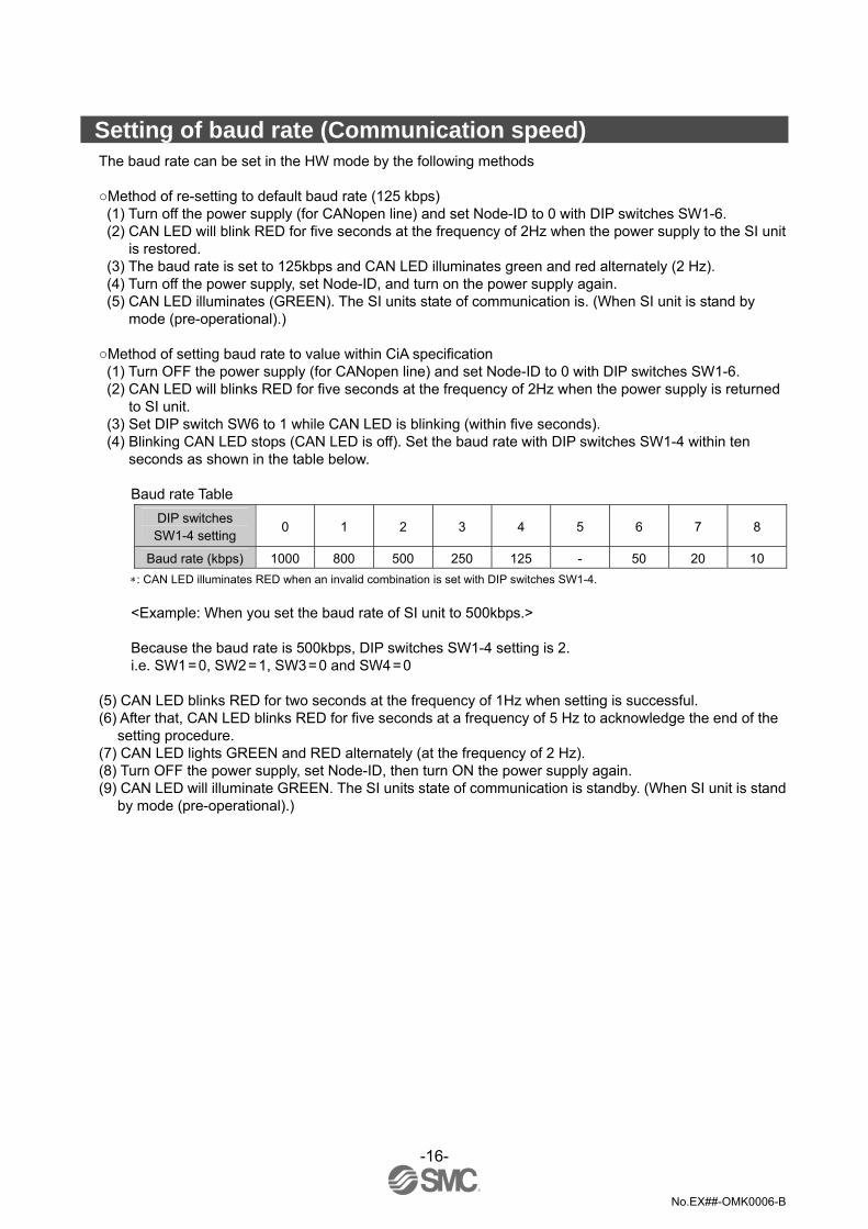
Setting of baud rate (Communication speed) The baud rate can be set in the HW mode by the following methods Method of re-setting to default baud rate (125 kbps) (1) Turn off the power supply (for CANopen line) and set Node-ID to 0 with DIP switches SW1-6. (2) CAN LED will blink RED for five seconds at the frequency of 2Hz when the power supply to the SI unit
is restored. (3) The baud rate is set to 125kbps and CAN LED illuminates green and red alternately (2 Hz). (4) Turn off the power supply, set Node-ID, and turn on the power supply again. (5) CAN LED illuminates (GREEN). The SI units state of communication is. (When SI unit is stand by
mode (pre-operational).) Method of setting baud rate to value within CiA specification (1) Turn OFF the power supply (for CANopen line) and set Node-ID to 0 with DIP switches SW1-6. (2) CAN LED will blinks RED for five seconds at the frequency of 2Hz when the power supply is returned
to SI unit. (3) Set DIP switch SW6 to 1 while CAN LED is blinking (within five seconds). (4) Blinking CAN LED stops (CAN LED is off). Set the baud rate with DIP switches SW1-4 within ten
seconds as shown in the table below.
Baud rate Table DIP switches SW1-4 setting
0 1 2 3 4 5 6 7 8
Baud rate (kbps) 1000 800 500 250 125 - 50 20 10 ∗: CAN LED illuminates RED when an invalid combination is set with DIP switches SW1-4.
<Example: When you set the baud rate of SI unit to 500kbps.>
Because the baud rate is 500kbps, DIP switches SW1-4 setting is 2. i.e. SW1 = 0, SW2 = 1, SW3 = 0 and SW4 = 0
(5) CAN LED blinks RED for two seconds at the frequency of 1Hz when setting is successful. (6) After that, CAN LED blinks RED for five seconds at a frequency of 5 Hz to acknowledge the end of the
setting procedure. (7) CAN LED lights GREEN and RED alternately (at the frequency of 2 Hz). (8) Turn OFF the power supply, set Node-ID, then turn ON the power supply again. (9) CAN LED will illuminate GREEN. The SI units state of communication is standby. (When SI unit is stand
by mode (pre-operational).)

-17-
No.EX##-OMK0006-B
Overview object dictionary for communication object area Index Sub-Index Object Name Type Acc Default 1000 VAR device type Unsigned32 ro 1001 VAR error register Unsigned8 ro 1002 VAR manufacturer status register Unsigned32 ro 1003 ARRAY pre-defined error register Unsigned32 ro
0 VAR number of errors Unsigned8 rw 00H 1 VAR standard error field Unsigned32 ro 2-8 VAR standard error field Unsigned32 ro
1005 VAR COB-ID SYNC Unsigned32 rw 00000080H 1006 VAR communication cycle period Unsigned32 rw 00000000H 1008 VAR manufacturer device name Vis-String const 1009 VAR manufacturer hardwear version Vis-String const 100A VAR manufacturer softwear version Vis-String const 100C VAR guard time Unsigned16 rw 0000H 100D VAR life time factor Unsigned8 rw 00H 1010 ARRAY store parameters Unsigned32 rw
0 VAR largest subindex supported Unsigned8 ro 1 VAR save all parameters Unsigned32 rw
1011 ARRAY restore default parameters Unsigned32 rw 0 VAR largest subindex supported Unsigned8 ro 1 VAR restore all default parameters Unsigned32 rw
1014 VAR COB-ID EMCY Unsigned32 ro 1016 ARRAY Consumer heartbeat time Unsigned32 rw
0 VAR number of entries Unsigned8 ro 1 VAR Consumer heartbeat time Unsigned32 rw 00000000H 2-9 VAR Consumer heartbeat time Unsigned32 rw 00000000H
1017 VAR Producer heartbeat time Unsigned16 rw 0000H 1018 RECORD identity object Identity(0023h) ro
0 VAR number of entries Unsigned8 ro 1 VAR vender ID Unsigned32 ro 2 VAR product code Unsigned32 ro 3 VAR revision number Unsigned32 ro 4 VAR serial number Unsigned32 ro
Server SDO Parameter 1200 RECORD 1st server SDO parameter SDO Prarameter(22h) ro
0 VAR number of entries Unsigned8 ro 1 VAR COB-ID client->server Unsigned32 ro $NODEID+600H 2 VAR COB-ID server->client Unsigned32 ro $NODEID+580H
Receive PDO Communication Parameter 1400 RECORD 1st receive PDO parameter PDO ommPar(20h) ro
0 VAR largest subindex supported Unsigned8 ro 1 VAR COB-ID used by PDO Unsigned32 rw $NODEID+200H 2 VAR transmission type Unsigned8 rw FFH
-18-
No.EX##-OMK0006-B
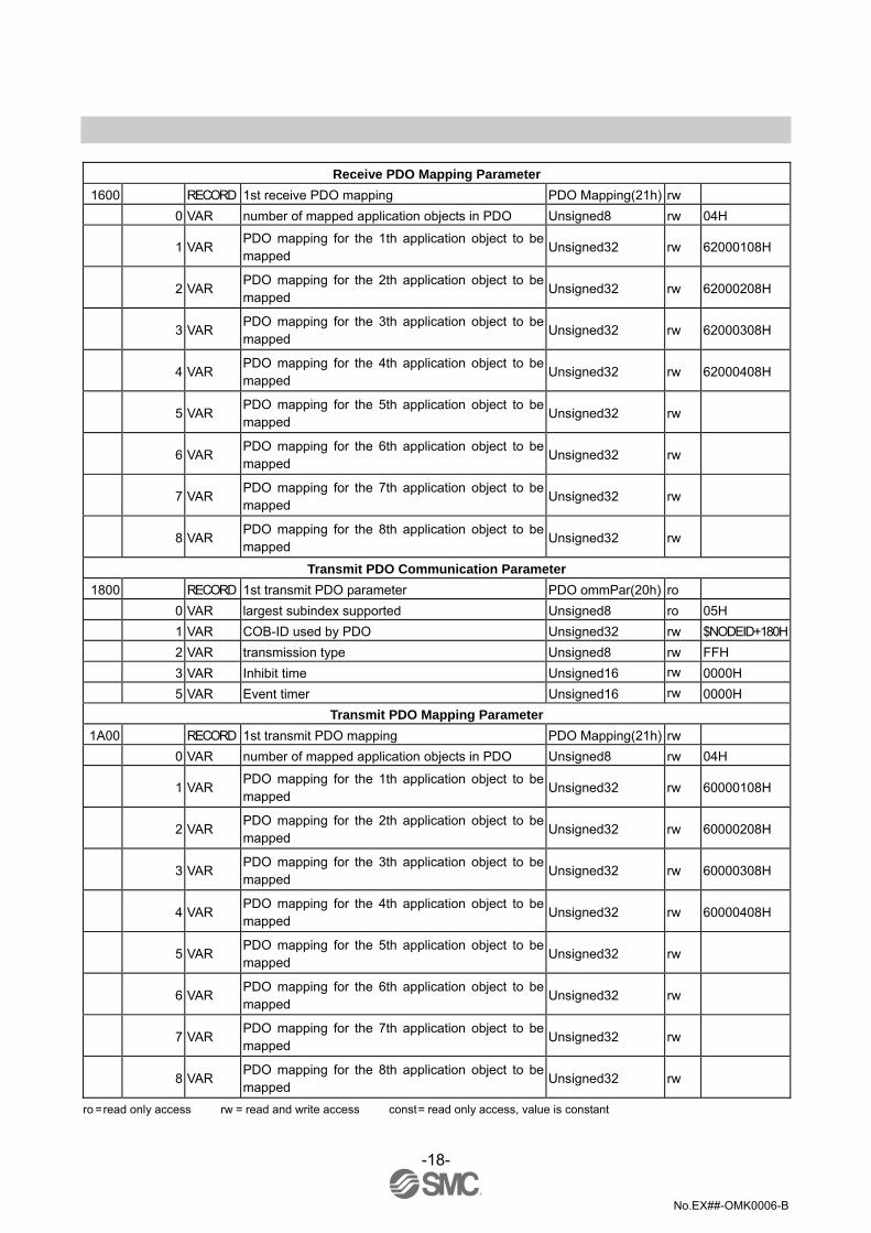
Receive PDO Mapping Parameter 1600 RECORD 1st receive PDO mapping PDO Mapping(21h) rw
0 VAR number of mapped application objects in PDO Unsigned8 rw 04H
1 VAR PDO mapping for the 1th application object to be mapped
Unsigned32 rw 62000108H
2 VAR PDO mapping for the 2th application object to be mapped
Unsigned32 rw 62000208H
3 VAR PDO mapping for the 3th application object to be mapped
Unsigned32 rw 62000308H
4 VAR PDO mapping for the 4th application object to be mapped
Unsigned32 rw 62000408H
5 VAR PDO mapping for the 5th application object to be mapped
Unsigned32 rw
6 VAR PDO mapping for the 6th application object to be mapped
Unsigned32 rw
7 VAR PDO mapping for the 7th application object to be mapped
Unsigned32 rw
8 VAR PDO mapping for the 8th application object to be mapped
Unsigned32 rw
Transmit PDO Communication Parameter 1800 RECORD 1st transmit PDO parameter PDO ommPar(20h) ro
0 VAR largest subindex supported Unsigned8 ro 05H 1 VAR COB-ID used by PDO Unsigned32 rw $NODEID+180H 2 VAR transmission type Unsigned8 rw FFH 3 VAR Inhibit time Unsigned16 rw 0000H 5 VAR Event timer Unsigned16 rw 0000H
Transmit PDO Mapping Parameter 1A00 RECORD 1st transmit PDO mapping PDO Mapping(21h) rw
0 VAR number of mapped application objects in PDO Unsigned8 rw 04H
1 VAR PDO mapping for the 1th application object to be mapped
Unsigned32 rw 60000108H
2 VAR PDO mapping for the 2th application object to be mapped
Unsigned32 rw 60000208H
3 VAR PDO mapping for the 3th application object to be mapped
Unsigned32 rw 60000308H
4 VAR PDO mapping for the 4th application object to be mapped
Unsigned32 rw 60000408H
5 VAR PDO mapping for the 5th application object to be mapped
Unsigned32 rw
6 VAR PDO mapping for the 6th application object to be mapped
Unsigned32 rw
7 VAR PDO mapping for the 7th application object to be mapped
Unsigned32 rw
8 VAR PDO mapping for the 8th application object to be mapped
Unsigned32 rw
ro = read only access rw = read and write access const = read only access, value is constant

-19-
No.EX##-OMK0006-B
Index 1000h Device Type This object describes the type of device and its functionality. The type of SI unit is as follows.
•General Information Device profile number: 0191h
•Additional Information I/O Functionality: 00000011 (Digital Input /Output) Specific Functionality: 00h (No Specific Function)
Index 1001h Error Register This object is an error register for the SI unit .It is a part of an Emergency object. If Error has occurred, a bit is set to 1.
Bit Meaning Content 0 Generic Error 1 Current Non-correspondence (always 0) 2 Voltage Non-correspondence (always 0) 3 Temperature Non-correspondence (always 0) 4 Communication Error CAN Over-run , CAN Error , Bus Off 5 Device Profile Specific Non-correspondence (always 0) 6 Reserved always 0 7 Manufacturer Specific Heartbeat, Node Guarding, Self-diagnosis
Structure of the Error Register
Index 1002h Manufacturer Status Register This object is used when Self-diagnosis Error for SI unit occurs. If Error has occurred, a bit is set to 1.
Reserved X X X X DI SOLV X X
SOLV: When the power supply for the valve is supplied, SOLV Status is 0. When the power supply for the valve is not supplied, SOLV Status is 1.
DI: When the error of the Input Block occurs (e.g. blow a fuse), DI Status is 1.
When the Input Block is normal, DI Status is 0.
31 MSB
8 7 0LSB
X and Reserved = 0

-20-
No.EX##-OMK0006-B
Index 1003h Pre-defined Error Field This object holds the errors that have occurred on the SI unit and have been signaled via the Emergency Object. The entry at Sub-Index 0 describes the number of errors that have been stored. Every new error is stored at Sub-Index 1, the older ones move down the list. If 0 is written at the Sub-Index 0, error history is deleted. Values higher than 0 are prevented from being written.
Index 1005h COB-ID SYNC message This object defines the COB-ID of the Synchronization Object (SYNC).
Bit number Value meaning 31 (MSB) X do not care
0 Device does not generate SYNC message ∗ 30
1 Device generate SYNC message 0 11 bit ID (CAN 2.0A) ∗
29 1 29 bit ID (CAN 2.0B) 0 if bit 29 = 0 ∗
28 - 1 X If bit 29 = 1, bits 28 - 11 of 29 - bit - SYNC - COB-ID
10-0 (LSB) X bits 10 - 0 of SYNC - COB - ID ∗ : The default values when the SI unit is supplied.
Bits 29 - 11 are fixed (not changeable). As an example, if an attempt is made to set bit 29 to 1, the SI unit will respond with an abort message.
Index 1006h Communication Cycle period When bit 30 of Index 1005h (COB - ID SYNC) is set to 1 (SYNC, Producer), the SYNC message is transmitted at intervals set to this object. The time can be set in multiples of 1us.
Index 100Ch Guard Time Refer to 7 - 8. Index 100Dh Life Time Factor.
Index 100Dh Life Time Factor The Life Time for the Life Guarding Protocol is given by multiplying Guard Time and Life Time Factor. SI unit supports Node/Life Guarding Protocol by setting Index 100C and Index 100D. If these objects are set to 0, SI unit does not support Node/Life Guarding Protocol. These objects are set the time in multiples of 1 ms.

-21-
No.EX##-OMK0006-B
Index 1010h Store parameters The various parameters can be saved in internal EEPROM of the SI unit by using this object. The parameters that can be saved in internal EEPROM of the SI unit are as follows:-
Index Sub - Index Name 1005 COB - ID, SYNC
1006 Communication cycle period 100C guard time
100D life time factor
1016 1 - 9 Consumer heartbeat time 1017 Producer heartbeat time 1400 1 - 2 1st receive PDO parameter 1600 0 - 8 1st receive PDO mapping 1800 1-3,5 COB-ID used by PDO 1A00 0 - 8 1st transmit PDO mapping
6206 1 - 4 Error Mode Output 8-bit 6207 1 - 4 Error Value Output 8-bit 6306 1 - 2 Error Mode Output 16-bit 6307 1 - 2 Error Value Output 16 - bit 6326 1 Error Mode Output 32 - bit 6327 1 Error Value Output 32 - bit
Object that can be written by “Store parameters”. Index 1011h Restore Default parameters The values in the internal EEPROM of the SI unit can be restored to their default values by using this object. A list of objects that can be restored to default values is mentioned. (Refer to table: object that can be written by “store parameters”). ∗: The default values become valid after the SI unit is reset (reset node, reset communication) or the power cycled. ROM = Read Only Memory, data can not be modified. (R) EEPROM = Memorize data although power is off. (R/W) RAM = Actual memory the SI - unit is working with. (R/W).
1. Reset node, Reset com or Power cycle: -
EEPROM is copied into RAM 2. STORE: -
Copy RAM (with modified/non - modified values) into EEPROM 3. RESTORE: -
Copy ROM (manufactures origin values) to EEPROM then copy EEPROM to RAM
∗: Index 1010h, 1011h Never turn off the power supply of the unit when you save the parameters to internal EEPROM. When the parameters are saved internal EEPROM, the unit will be damaged by turning off the power supply. To save the parameter to internal EEPROM, necessary time is about 1sec.
-22-
No.EX##-OMK0006-B
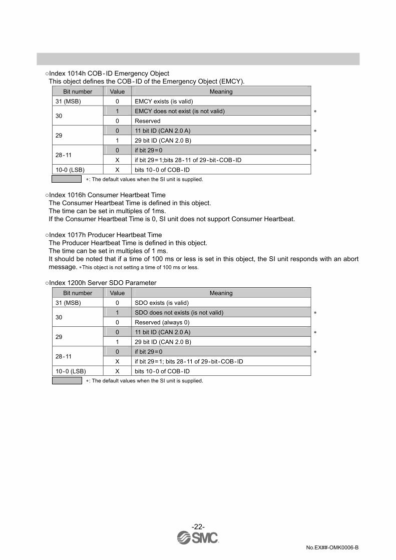
Index 1014h COB - ID Emergency Object This object defines the COB - ID of the Emergency Object (EMCY).
Bit number Value Meaning 31 (MSB) 0 EMCY exists (is valid)
1 EMCY does not exist (is not valid) ∗ 30
0 Reserved 0 11 bit ID (CAN 2.0 A) ∗
29 1 29 bit ID (CAN 2.0 B) 0 if bit 29 = 0 ∗
28 - 11 X if bit 29 = 1;bits 28 - 11 of 29 - bit - COB - ID
10-0 (LSB) X bits 10 - 0 of COB - ID ∗: The default values when the SI unit is supplied.
Index 1016h Consumer Heartbeat Time The Consumer Heartbeat Time is defined in this object. The time can be set in multiples of 1ms. If the Consumer Heartbeat Time is 0, SI unit does not support Consumer Heartbeat.
Index 1017h Producer Heartbeat Time The Producer Heartbeat Time is defined in this object. The time can be set in multiples of 1 ms. It should be noted that if a time of 100 ms or less is set in this object, the SI unit responds with an abort message. ∗This object is not setting a time of 100 ms or less.
Index 1200h Server SDO Parameter Bit number Value Meaning
31 (MSB) 0 SDO exists (is valid) 1 SDO does not exists (is not valid) ∗
30 0 Reserved (always 0) 0 11 bit ID (CAN 2.0 A) ∗
29 1 29 bit ID (CAN 2.0 B) 0 if bit 29 = 0 ∗
28 - 11 X if bit 29 = 1; bits 28 - 11 of 29 - bit - COB - ID
10 - 0 (LSB) X bits 10 - 0 of COB - ID ∗: The default values when the SI unit is supplied.

-23-
No.EX##-OMK0006-B
Index 1400h Receive PDO Communication Parameter Index1400h_Sub - Index1 means COB - ID of PDO.
Bit number Value Meaning 31 (MSB) 0 PDO exists (is valid)
1 PDO does not exist (is not valid) ∗ 30
0 RTR allowed on this PDO 1 no RTR allowed on this PDO ∗
29 0 11 bit ID (CAN 2.0 A) 1 29 bit ID (CAN 2.0 B) ∗
28 - 11 0 if bit 29 = 0
10 - 0 (LSB) X if bit 29 = 1: bits 28 - 11 of 29 - bit - COB - ID ∗: The default values when the SI unit is supplied.
Index1400h_Sub - Index2 means transmission type of PDO.
Transmission type Meaning
0 - 240 When the next SYNC message is received, the PDO data is processed. The value of the transmission type is irrelevant.
241 - 253 No used 254 It is the same as 255. (It differs according to the manufacturer). 255 (default) When the PDO data is received, the data is processed at once.
Index 1600h Receive PDO Mapping Parameter Sub - Index0: Number of mapped application objects in PDO. Sub - Index1 - 8: The sub - index (from 1h to number of entries) contain the information about the mapped
application variables. ∗: When SI unit is shipped, the mapping is done from Sub - Index1 to Sub-Index4.
The structure of the entries from sub - index 1-8 is as follows:-
Index (16 bit) Sub-Index (8 bit ) Length (8 bit)
Structure of PDO Mapping Entry
(MSB)31 16 15 8 7 0 (LSB)

-24-
No.EX##-OMK0006-B
Index 1800h Transmit PDO Communication Parameter Index1800h_Sub-Index1 means COB-ID of PDO.
Bit number Value Meaning 31 (MSB) 0 PDO exists (is valid)
1 PDO does not exist (is not valid) ∗ 30
0 RTR allowed on this PDO 1 no RTR allowed on this PDO ∗
29 0 11 bit ID (CAN 2.0 A) 1 29 bit ID (CAN 2.0 B) ∗
28-11 0 if bit 29 = 0
10-0 (LSB) X if bit 29 = 1: bits 28-11 of 29-bit-COB-ID ∗: The default values when the SI unit is supplied.
Index1800h_Sub-Index2 means transmission type of PDO.
Transmission type Meaning 0 When the next SYNC message is received, the PDO data is transmitted. 1-240 (N) When the SYNC message of time N is received, the PDO data is transmitted. 241-251 Not used
252 When the next SYNC message is received, the PDO is not transmitted though the PDO data is updated. When RTR is received, the PDO is transmitted.
253 When RTR is received, the PDO data is transmitted. 254 It is the same as 255 (It differs according to the manufacturer). 255 (default) When the PDO data is updated, the data is transmitted at once.
Index1800h_Sub-Index3 means inhibit time. The time can be set in multiples of 100us. Index1800h_Sub-Index5 means event timer. The time can be set in multiples of 1ms.
Index 1A00h Transmit PDO Mapping Parameter Sub-Index0: Number of mapped application objects in PDO. Sub-Index1-8: The sub-index (from 1h to number of entries) contain the information about the mapped
application variables. ∗: When SI unit is shipped, the mapping is done from Sub-Index1 to Sub-Index4.
The structure of the entries from sub-index 1-8 is as follows.
Index (16 bit) Sub-Index (8 bit) Length (8 bit)
Structure of PDO Mapping Entry
(MSB)31 16 15 8 7 0 (LSB)

-25-
No.EX##-OMK0006-B
Overview object dictionary for manufacturer specific area
Index Sub-Index Object Name Type Acc Default
2000 VAR Reserve Unsigned32 ro 2001 VAR Password Unsigned16 wo
ro = read only access wo = write only access
Index 2000h Reserve This object is not used.
Index 2001h Password This object is a manufacturing password so is not supplied to the user.
∗: For making sure that the machine works fine, the machine builder is responsible. As for CANopen unit made of each maker, the ability (Minimum massage interval) is different respectively. The machine builder should consider the difference of the ability. Method (confirmed service) of sending the following request after the response to the request is received to communicate surely is recommended. When you use method (unconfirmed service) of sending the following request without receiving the response to the request, If the request which exceeds the processing performance of each unit is sent, it is not treatable. Please confirm the normal operation beforehand when our unit is used for your machine. Please consult our company when there is a problem.

-26-
No.EX##-OMK0006-B
Overview object dictionary for device profile specific area
Index Sub-Index Object Name Type Acc Default Digital Input Module
6000 ARRAY Read Inputs 8-bit 0 VAR Number of inputs 8-bit Unsigned8 ro 1 VAR Read Inputs 1h-8h Unsigned8 ro 2 VAR Read Inputs 9h-16h Unsigned8 ro 3 VAR Read Inputs 17h-24h Unsigned8 ro 4 VAR Read Inputs 25h-32h Unsigned8 ro
6100 ARRAY Read Inputs 16-bit 0 VAR Number of inputs 16-bit Unsigned8 ro 1 VAR Read Inputs 1h-16h Unsigned16 ro 2 VAR Read Inputs 17h-32h Unsigned16 ro
6120 ARRAY Read Inputs 32-bit 0 VAR Number of inputs 32-bit Unsigned8 ro 1 VAR Read Inputs 1h-32h Unsigned32 ro
Digital Output Module 6200 ARRAY Write Outputs 8-bit
0 VAR Number of outputs 8-bit Unsigned8 ro 1 VAR Write Outputs 1h-8h Unsigned8 rw 00H 2 VAR Write Outputs 9h-16h Unsigned8 rw 00H 3 VAR Write Outputs 17h-24h Unsigned8 rw 00H 4 VAR Write Outputs 25h-32h Unsigned8 rw 00H
6206 ARRAY Error Mode Outputs 8-bit 0 VAR Number of outputs 8-bit Unsigned8 ro 1 VAR Error Mode Outputs 1h to 8h Unsigned8 rw FFH 2 VAR Error Mode Outputs 9h to 16h Unsigned8 rw FFH 3 VAR Error Mode Outputs 17h to 24h Unsigned8 rw FFH 4 VAR Error Mode Outputs 25h to 32h Unsigned8 rw FFH
6207 ARRAY Error Value Outputs 8-bit 0 VAR Number of outputs 8-bit Unsigned8 ro 1 VAR Error Value Outputs 1h to 8h Unsigned8 rw 00H 2 VAR Error Value Outputs 9h to 16h Unsigned8 rw 00H 3 VAR Error Value Outputs 17h to 24h Unsigned8 rw 00H 4 VAR Error Value Outputs 25h to 32h Unsigned8 rw 00H
6300 ARRAY Write Outputs 16-bit 0 VAR Number of outputs 16-bit Unsigned8 ro 1 VAR Write Outputs 1h-16h Unsigned16 rw 0000H 2 VAR Write Outputs 17h-32h Unsigned16 rw 0000H
6306 ARRAY Error Mode Outputs 16-bit 0 VAR Number of outputs 16-bit Unsigned8 ro 1 VAR Error Mode Outputs 1h to 16h Unsigned16 rw FFFFH 2 VAR Error Mode Outputs 17h to 32h Unsigned16 rw FFFFH
ro = read only access rw = read and write access

-27-
No.EX##-OMK0006-B
Digital Output Module 6307 ARRAY Error Value Outputs 16-bit
0 VAR Number of outputs 16-bit Unsigned8 ro 1 VAR Error Value Outputs 1h to 16h Unsigned16 rw 0000H 2 VAR Error Value Outputs 17h to 32h Unsigned16 rw 0000H
6320 ARRAY Write Outputs 32-bit 0 VAR Number of outputs 32-bit Unsigned8 ro 1 VAR Write Outputs 1h-32h Unsigned32 rw 00000000H
6326 ARRAY Error Mode Outputs 32-bit 0 VAR Number of outputs 32-bit Unsigned8 ro 1 VAR Error Mode Outputs 1h to 32h Unsigned32 rw FFFFFFFFH
6327 ARRAY Error Value Outputs 32-bit 0 VAR Number of outputs 32-bit Unsigned8 ro 1 VAR Error Value Outputs 1h to 32h Unsigned32 rw 00000000H
ro = read only access rw = read and write access

-28-
No.EX##-OMK0006-B
Index 6000h Read Inputs 8- This object shall read groups of 8 input lines as 8-bit information. Sub-Index 0: Number of Inputs 8-Bit (Number of Sub-Index) Sub-Index 1: Input Data 0 – 7th Bit Sub-Index 2: Input Data 8 – 15th Bit Sub-Index 3: Input Data 16 – 23rd Bit Sub-Index 4: Input Data 24 – 31st Bit
Index 6100h Read Inputs 16-Bit This object shall read a group of 16 input lines as 16-bit information. Sub-Index 0: Number of Inputs 16-Bit (Number of Sub-Index) Sub-Index 1: Input Data 0 – 15th Bit Sub-Index 2: Input Data 16 – 31st Bit
Index 6120h Read Inputs 32-Bit This object shall read a group of 32 input lines as 32-bit information. Sub-Index 0: Number of Inputs 32-Bit (Number of Sub-Index) Sub-Index 1: Input Data 0 – 31st Bit
Index 6200h Write Outputs 8-Bit This object shall set a group of 8 output lines as 8-bit information. Sub-Index 0: Number of Outputs 8-Bit (Number of Sub-Index) Sub-Index 1: Output Data 0 – 7th Bit Sub-Index 2: Output Data 8 – 15th Bit Sub-Index 3: Output Data 16 – 23rd Bit Sub-Index 4: Output Data 24 – 31st Bit
Index 6206h Error Mode Outputs 8-Bit This object indicates whether an output is set to a pre-defined error value when stopped state.
1 = the output value shall be set to the pre-defined condition specified in the 6207h object 0 = the output value shall be retained The value in the EEPROM (Index 6206h) depends on the status of DIP Switch SW9 If DIP switch SW9 is 0 (OFF), the value of Index 6206h is FFh. (This is default value) If DIP switch SW9 is 1 (ON), the value of Index 6206h is 00h. However, if the value of Index 6206h is changed and “Store Parameters” is executed, the set value is saved in internal EEPROM of the SI unit. After that the SI unit will use this value until the default value of FFh is set or a “Restore default parameters” is executed.

-29-
No.EX##-OMK0006-B
∗: If “Store Parameters” is not executed when the value of Index 6206h is changed, the value is not saved in internal EEPROM of SI
unit.
Sub-Index 0: Number of Outputs 8-Bit (Number of Sub-Index) Sub-Index 1: Error Mode Output Data 0 – 7th Bit Sub-Index 2: Error Mode Output Data 8 – 15th Bit Sub-Index 3: Error Mode Output Data 16 – 23rd Bit Sub-Index 4: Error Mode Output Data 24 – 31st Bit
Index 6207h Error Value Outputs 8-Bit When DIP switch SW9 is set to 0 or the value of Index 6206h is 1, the SI unit will reflect the value of Index 6207h. 0 = Output will be set to 0. (Output clear) 1 = Output will be set to 1. (Output on)
Index 6300h Write Outputs 16-Bit This object shall set a group of 16 output lines as 16-Bit information.
Sub-Index 0: Number of Outputs 16-Bit (Number of Sub-Index) Sub-Index 1: Output Data 0 – 15th Bit Sub-Index 2: Output Data 16 – 31st Bit
Index 6306h Error Mode Outputs 16-Bit This object indicates whether an output is set to a pre-defined error value when stopped state.
1 = the output value shall be set to the pre-defined condition specified in the 6307h object 0 = the output value shall be retained The SI unit reflects the status of the DIP switch SW9 when the value of the index 6306h in the internal EEPROM of the SI unit is FFFFh (default). If DIP switch SW9 is 0 (OFF), the value of Index 6306h is FFFFh. (This is default value) If DIP switch SW9 is 1 (ON), the value of Index 6306h is 0000h. If the value of Index 6306h is changed and “Store Parameters” is executed, the set value is saved in the internal EEPROM of the SI unit. After this, the SI unit operates by setting a value until the value of Index 6306h is set to the default value (FFFFh) or “Restore default parameters” is executed.
∗: If “Store Parameters” is not executed when the value of Index 6306h is changed, the value is not saved in internal EEPROM of SI unit.
Sub-Index 0: Number of Outputs 16-Bit (Number of Sub-Index) Sub-Index 1: Error Mode Output Data 0 – 15th Bit Sub-Index 2: Error Mode Output Data 16 – 31st Bit

-30-
No.EX##-OMK0006-B
Index 6307h Error Value Outputs 16-Bit When DIP switch SW9 is set to 0 or the value of Index 6306h is 1, the SI unit reflects the value of Index 6307h.
0 = The output shall be set to 0. (Output clear) 1 = The output shall be set to 1. (Output on)
Index 6320h Write Outputs 32-Bit This object shall set a group of 8 outputs lines as 32-Bit of information. Sub-Index 0: Number of Outputs 32-Bit (Number of Sub-Index) Sub-Index 1: Output Data 0 – 31st Bit
Index 6326h Error Mode Outputs 32-Bit This object indicates whether an output is set to a pre-defined error value when stopped state. 1 = the output value shall be set to the pre-defined condition specified in the 6327h object 0 = the output value shall be retained. The SI unit reflects the status of the DIP switch SW9 when the value of Index 6326h in internal EEPROM of SI unit is default (FFFFFFFFh). If DIP switch SW9 is 0 (OFF), the value of Index 6326h is FFFFFFFFh. (This is default value) If DIP switch SW9 is 1 (ON), the value of Index 6326h is 00000000h. If the value of Index 6326h is changed and “Store Parameters” is executed, the set value is saved in the internal EEPROM of the SI unit. After that, the SI unit operates by setting the value until the value of Index 6326h is set to the default value (FFFFFFFFh) or “Restore default parameters” is executed. ∗: If “Store Parameters” is not executed when the value of Index 6326h is changed, the value is not savedin internal EEPROM of SI
unit. Sub-Index 0: Number of Outputs 32-Bit (Number of Sub-Index) Sub-Index 1: Error Mode Output Data 0 – 31st Bit
Index 6327h Error Value Outputs 32-Bit When DIP switch SW9 is set to 0 or the value of Index 6326h is 1, SI unit reflects the value of Index 6327h. 0 = The output shall be set to 0. (Output clear) 1 = The output shall be set to 1. (Output on)

-31-
No.EX##-OMK0006-B
Error control services SI unit supports both Node Guarding Protocol and Heartbeat Protocol. Node Guarding Protocol can be used by setting Index 100Ch and Index 100Dh Objects. Heartbeat Protocol can be used by setting Index 1016h and Index 1017h Objects. Error Control Services are not set on shipment. (100C, 100D, 1016, 1017h = 0) Node Guarding Protocol and Heartbeat Protocol are not able to be used at the same time. If both Node Guarding Protocol and Heartbeat Protocol are set at the same time, the Heartbeat Protocol is used.
There are the following possibilities:-
Heartbeat Protocol Node Guarding Life Guarding
Heartbeat is configured; Node and Life guarding are also configured
ON OFF OFF
Heartbeat is configured; Node and Life guarding are not configured
ON OFF OFF
Heartbeat is not configured; Node and Life guarding are configured
OFF ON ON
Node guarding is configured; Heartbeat and Life guarding are not configured
OFF ON OFF
The possibilities of Error Control Services Node Guarding Protocol This protocol is used to detect remote errors in the network. Each NMT Slave uses one remote COB for the Node Guarding Protocol. This protocol implements the provider initiated Error Control Services. Life Guarding is set by the Guard Time (Index 100C) multiplied by the Life Time Factor (Index 100D). Life Guarding starts when SI unit receives the first Remote-Transmit - Request (RTR). If the SI unit does not receive RTR for the Node Life Time, the SI unit will be informed about that event. (The SI unit sends the Emergency Object).
∗: If the Guard Time (Index 100C) and Life Time Factor (Index 100D) are set to 0, the Node Guarding Protocol (Error Control Services) is not set, however, even when neither the Heartbeat Protocol nor Node Guarding Protocol are set, the SI unit returns the response if the SI unit receives RTR.
Heartbeat Producer Protocol The Heartbeat Producer transmits a Heartbeat Message cyclically at the Producer Heartbeat Time (Index 1017h: Producer Heartbeat Time). Heartbeat Consumer Protocol The Heartbeat Consumer guards the reception of the Heartbeat within the Heartbeat Consumer Time (Index 1016h_Sub-Index1: Consumer Heartbeat Time) If SI unit does not receive a message by a Heartbeat Producer for the Heartbeat Consumer Time, the SI unit will be informed about that event. (The SI unit sends the Emergency Object). ∗: If the Heartbeat Consumer Time (Index 1016h_Sub-Index1) is set to 0, the Heartbeat Protocol (Error Control Services) is not set.
-32-
No.EX##-OMK0006-B
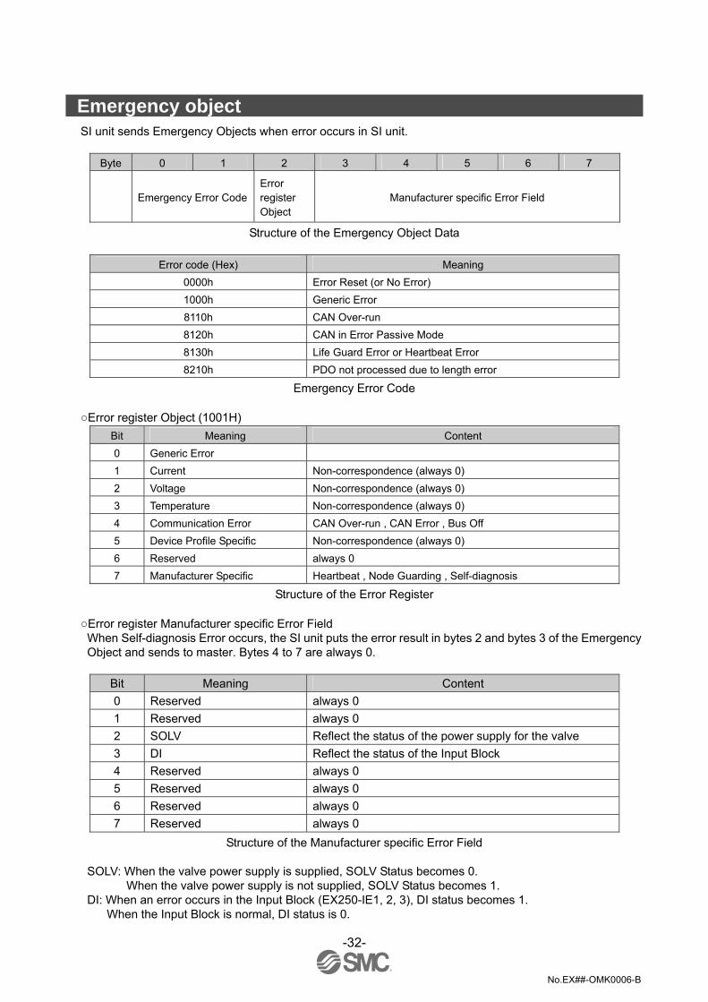
Emergency object SI unit sends Emergency Objects when error occurs in SI unit.
Byte 0 1 2 3 4 5 6 7
Emergency Error Code Error register Object
Manufacturer specific Error Field
Structure of the Emergency Object Data
Error code (Hex) Meaning 0000h Error Reset (or No Error) 1000h Generic Error 8110h CAN Over-run 8120h CAN in Error Passive Mode 8130h Life Guard Error or Heartbeat Error 8210h PDO not processed due to length error
Emergency Error Code Error register Object (1001H)
Bit Meaning Content 0 Generic Error 1 Current Non-correspondence (always 0) 2 Voltage Non-correspondence (always 0) 3 Temperature Non-correspondence (always 0) 4 Communication Error CAN Over-run , CAN Error , Bus Off 5 Device Profile Specific Non-correspondence (always 0) 6 Reserved always 0 7 Manufacturer Specific Heartbeat , Node Guarding , Self-diagnosis
Structure of the Error Register Error register Manufacturer specific Error Field When Self-diagnosis Error occurs, the SI unit puts the error result in bytes 2 and bytes 3 of the Emergency Object and sends to master. Bytes 4 to 7 are always 0.
Bit Meaning Content 0 Reserved always 0 1 Reserved always 0 2 SOLV Reflect the status of the power supply for the valve 3 DI Reflect the status of the Input Block 4 Reserved always 0 5 Reserved always 0 6 Reserved always 0 7 Reserved always 0
Structure of the Manufacturer specific Error Field
SOLV: When the valve power supply is supplied, SOLV Status becomes 0. When the valve power supply is not supplied, SOLV Status becomes 1.
DI: When an error occurs in the Input Block (EX250-IE1, 2, 3), DI status becomes 1. When the Input Block is normal, DI status is 0.

-33-
No.EX##-OMK0006-B
Service data object (SDO) SDO Upload
•Initiate SDO Upload This protocol is used when the size of the data to be uploaded is 4 bytes or less. When the data size exceeds 4 bytes, the number of uploaded data bytes is transmitted.
•Upload SDO Segment This protocol is used when the size of the data to upload exceeds 4 bytes. In this case, the upload data is transmitted by using the “Upload SDO Segment” after executing the “Initiate SDO Upload”. The maximum data size in 1 data frame is 7 Bytes. When the data size exceeds 7 Bytes, "Upload SDO Segment" has to be executed until all data is sent from the server of the SDO to the client.
SDO Download
•Initiate SDO Download This protocol is used when the size of the data to be downloaded is 4 bytes or less. When the data size exceeds 4 bytes, the number of downloaded data bytes is transmitted.
•Download SDO Segment This protocol is used when the size of the data to download exceeds 4 Bytes. In this case, the download data is transmitted by using the “Download SDO Segment” after executing the “Initiate SDO Download”. The maximum data size in 1 data frame is 7 Bytes. When the data size exceeds 7 Bytes, "Download SDO Segment" has to be executed until all data is sent from the client of the SDO to the server.
Abort SDO transfer The SI unit sends an abort code, which is encoded as an UNSIGNED32 (4 byte data) value. When something wrong is found in the message from the SDO server, the SI unit sends the message which is referred to in the table below.
Abort code Description 0504 0001h Client/server command specifier not valid or unknown 0601 0001h Attempt to read a write only object. 0601 0002h Attempt to write a read only object. 0602 0000h Object does not exist in the object dictionary. 0604 0041h Object cannot be mapped to the PDO. 0604 0043h General parameter incompatibility reason. 0607 0010h Data type does not match , length of service parameter does not match 0609 0011h Sub-index does not exist. 0609 0030h Value range of parameter exceeded (only for write access). 0609 0032h Value of parameter written too low. 0800 0000h general error 0800 0020h Data cannot be transferred or stored to the application. 0800 0021h Data cannot be transferred of stored to the application because of local control. 0800 0022h Data cannot be transferred or stored to the application because of the present device state.
SDO abort codes

-34-
No.EX##-OMK0006-B
Process data object (PDO) The SI unit receives and outputs the N data bytes that are defined by Object 1600h and 1A00h. The SI unit returns an Emergency Object (Error Code: 8210h) when the data that the SI unit receives is smaller than N bytes. SI unit outputs the first N bytes of data as “pertinent data” when the data that the SI unit receives is larger than N bytes. The SI unit supports Dynamic Mapping and Dummy Entry and variable COB-ID. When more than two slaves are used with the same COB-ID, Dummy Data may be needed. Dummy entries are only used within the received PDO. The dummy data that can be used with SI unit is shown below.
Index 0005h: Unsigned8 Index 0006h: Unsigned16 Index 0007h: Unsigned32
<For Example> Slave1 = > Node-ID = 1, COB-ID for RPDO = 420h (Index 1400_Sub1) ∗default 201h Slave2 = > Node-ID = 5, COB-ID for RPDO = 420h (Index 1400_Sub1) ∗default 205h ∗: SI unit supports variable COB-ID. Slave1 Mapping (1600h RPDO Mapping Parameter) 1600h_sub0 = 2 1600h_sub1 = 6320 01 20 (Object 6320h sub-index 1, length 32-bit) 1600h_sub2 = 6320 02 20 (Object 6320h sub-index 2, length 32-bit) Slave2 Mapping (1600h RPDO Mapping Parameter) 1600h_sub0 = 2 1600h_sub1 = 0007 00 20(Object 0007h (Unsigned 32) sub-index 0, length 32-bit) 1600h_sub2 = 6320 01 20(Object 6320h sub-index 1, length 32-bit) PDO Data from Master to each Slaves.
COB-ID 1th_data 2th_data 3th_data 4th_data 5th_data 6th_data 7th_data 8th_data
420h 12 34 56 78 9A BC DE FF Output status of Slave1 and Slave2
COB-ID 1th_data 2th_data 3th_data 4th_data 5th_data 6th_data 7th_data 8th_data
6320h/01h 32 bit (Output 0-31 bit ) 6320h/02h 32 bit (Output 32-63 bit) 420h (Slave1) 12 34 56 78 9A BC DE FF
0007h/00h 32 bit 6320h/01h 32 bit (Output 0-31 bit) 420h (Slave2) Dummy Entry 12 34 56 78
∗: SI unit ignores the first 4-bytes of data (PDO Data from Master). ∗: SI unit supports valuable COB-ID, therefore, SI unit can set an arbitrary value, however, if you set COB-ID to SI unit, we recommend to
set Unused COB-ID (281h-57F) for safety reasons. Dynamic mapping is only possible in "pre-operational" mode.

-35-
No.EX##-OMK0006-B
Pre-defined connection set COB-Identifier
COB-Identifier allocation scheme for the pre-defined Connection set COB-ID is composed of 11 bits. The Function Code is allocated in bits 7 - 10 and the Node-ID is allocated in bits 0 - 6.
Object Function
Code Resulting COB-ID Communication Parameters at Index
NMT 0000 0 − SYNC 0001 128 (80h) 1005h Emergency 0001 129 (81h) – 255 (FFh) 1014h PDO(tx) 0011 385 (181h) – 511 (1FFh) 1800h PDO(rx) 0100 513 (201h) – 639 (27Fh) 1400h SDO(tx) 1011 1409 (581h) – 1535 (5FFh) 1200h SDO(rx) 1100 1537 (601h) – 1663 (67Fh) 1200h NMT Error Control 1110 1793 (701h) – 1919 (77Fh) 100Ch,100Dh,1016h,1017h
Objects of the Pre-defined Connection Set
All devices (clients) have to receive and correspond when NMT and SYNC Object are transmitted. The SI unit can change COB-ID of PDO (tx) and PDO (rx). (Index 1400h_01, Index 1800h_01) If COB-ID is changed and “Store Parameters” are not executed, SI unit operates according to above-mentioned COB-ID (refer to Objects within Pre-defined Connection Set) at the next Power Supply ON. ∗: The value is not saved in internal EEPROM of SI unit.
Layer setting services (LSS) SI unit supports LSS function, therefore SI unit supports the following function:-
•Switch Mode Services •Configuration Services •Inquiry Services •Identification Services
Request COB-ID is 2021 (7E5h) in the services. Response COB-ID is 2020 (7E4h) in the services. Request and Response COB-ID are all common in this LSS.

-36-
No.EX##-OMK0006-B
Switch Mode Services
•Switch Mode Global This service is used to switch all LSS Slaves in the network between operation mode and configuration mode.
cs: LSS command specifier (04h for Switch Mode Global) mode: 0 = Switches to Operation Mode
1 = Switches to Configuration Mode reserved: reserved for further use by CiA
•Switch Mode Selective This service is used to switch the LSS Slave whose LSS address attribute equals LSS_address, into configuration mode.
cs: LSS command specifier ( 40h to 44h for Switch Mode Selective ) vendor-ID: Vendor name. Part of the LSS address (Index 1018h sub-index 1) product-code: Product name. Part of LSS address (Index 1018h sub-index 2) revision-number: Revision. Part of the LSS address (Index 1018h sub-index 3) serial-number: Serial number. Part of the LSS address (Index 1018h sub-index 4)

-37-
No.EX##-OMK0006-B
Configuration Services This services are supported only at the SW mode (DipSW10 = 1). •Configure Node-ID This protocol is used to implement the “Configure Node-ID” service for the Node-ID part of NMT address. After switching back to LSS “Operation Mode” to “Configuration Mode” a change of the Node-ID will occur.
cs: LSS command specifier (11h for Configure Node-ID) NID: The new Node-ID to configure error code: 0: protocol successfully completed
1: Node-ID out of range 2-254: reserved for further use by CiA 255: implementation specific error occurred (not used)
spec error: not used
•Configure Bit Timing Parameters The bit Timing of LSS Slave can be changed by this service. This service allows only one LSS Slave in configuration mode. The service has to be followed by an “Activate Bit Timing Parameters” service to activate the configured parameters. After execution of the “Configure Bit Timing Parameters” service the node may not execute any remote LSS services expect the services “Configure Bit Timing Parameters services”, “Activate Bit Timing Parameters” and Switch Mode.
cs: LSS command specifier (13h for Configure Bit Timing Parameters) table selector: selects which bit timing parameters table has to be used
0: standard CiA bit timing table 1-127: reserved for further use by CiA 128-255: may be used for manufacturer specific bit timings (not used)
table index: selects the entry (bit timing parameters) in the selected table.
-38-
No.EX##-OMK0006-B
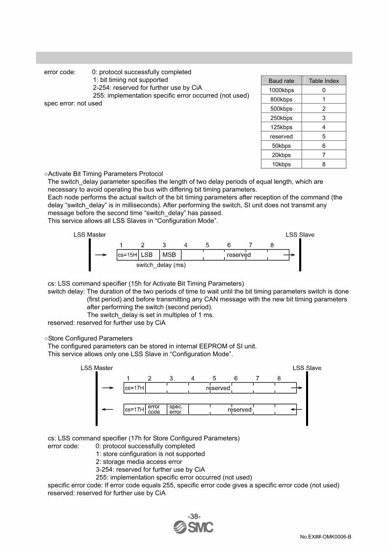
error code: 0: protocol successfully completed
1: bit timing not supported 2-254: reserved for further use by CiA 255: implementation specific error occurred (not used)
spec error: not used Activate Bit Timing Parameters Protocol The switch_delay parameter specifies the length of two delay periods of equal length, which are necessary to avoid operating the bus with differing bit timing parameters. Each node performs the actual switch of the bit timing parameters after reception of the command (the delay “switch_delay” is in milliseconds). After performing the switch, SI unit does not transmit any message before the second time “switch_delay” has passed. This service allows all LSS Slaves in “Configuration Mode”.
cs: LSS command specifier (15h for Activate Bit Timing Parameters) switch delay: The duration of the two periods of time to wait until the bit timing parameters switch is done
(first period) and before transmitting any CAN message with the new bit timing parameters after performing the switch (second period). The switch_delay is set in multiples of 1 ms.
reserved: reserved for further use by CiA Store Configured Parameters The configured parameters can be stored in internal EEPROM of SI unit. This service allows only one LSS Slave in “Configuration Mode”.
cs: LSS command specifier (17h for Store Configured Parameters) error code: 0: protocol successfully completed
1: store configuration is not supported 2: storage media access error 3-254: reserved for further use by CiA 255: implementation specific error occurred (not used)
specific error code: If error code equals 255, specific error code gives a specific error code (not used) reserved: reserved for further use by CiA
Baud rate Table Index 1000kbps 0 800kbps 1 500kbps 2 250kbps 3 125kbps 4 reserved 5 50kbps 6 20kbps 7 10kbps 8

-39-
No.EX##-OMK0006-B
Inquiry Services These services are supported only in configuration mode.
•Inquire LSS Address This service allows the determination of the LSS Address parameters of a LSS Slave in configuration mode.
cs: LSS command specifier (5Ah for Inquire Vendor-ID) cs: LSS command specifier (5Bh for Inquire Product-Code) cs: LSS command specifier (5Ch for Inquire Revision-Number) cs: LSS command specifier (5Dh for Inquire Serial-Number) reserved: reserved for further use by CiA

-40-
No.EX##-OMK0006-B
•Inquire Node-ID The service allows the determination of the Node-ID of a LSS Slave in configuration mode.
cs: LSS command specifier (5Eh for Inquire Node-ID) NID: The Node-ID of the selected module. If the Node-ID has been changed by means of previous
Configure Node-ID service, the original Node-ID is returned until the next power on reset. A value of FFh is returned if the Node-ID is not configured, which is only possible if the slave is in “LSS In it State”.
reserved: reserved for further use by CiA Identification Services These services are supported in configuration mode and operation mode.
•LSS Identify Remote Slaves LSS Master can confirm the presence of LSS Slave which is specified by this service. The LSS Slave with a corresponding address, returns “LSS Identify Slave”. Revision-Number and Serial-Number are specified within the range (Low and High).
cs: LSS command specifier (46h to 4Bh for LSS Identify Remote Slaves) reserved: reserved for further use by CiA
-41-
No.EX##-OMK0006-B
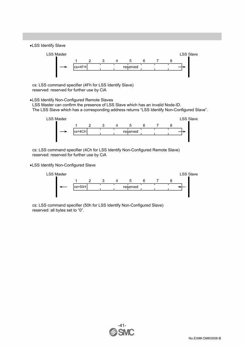
•LSS Identify Slave
cs: LSS command specifier (4Fh for LSS Identify Slave) reserved: reserved for further use by CiA
•LSS Identify Non-Configured Remote Slaves LSS Master can confirm the presence of LSS Slave which has an invalid Node-ID. The LSS Slave which has a corresponding address returns “LSS Identify Non-Configured Slave”.
cs: LSS command specifier (4Ch for LSS Identify Non-Configured Remote Slave) reserved: reserved for further use by CiA
•LSS Identify Non-Configured Slave
cs: LSS command specifier (50h for LSS Identify Non-Configured Slave) reserved: all bytes set to “0”.

-42-
No.EX##-OMK0006-B
•Assignment of I/O No. Correspondence between output data and valve manifold
*: Output numbers are assigned to stations from side D to U of manifold in order. (See manual of each valve manifold for the directions of side D and U)
*: Standard manifold is wired in double. Output numbers are assigned to side A and B alternatively. In case of single solenoid valve, output on side B is free. (Refer to fig.a)
*: Mixed (single and double) wiring is available as long as wiring specifications designate it. This allows output numbers to be specified without having free output. (Refer to fig.b)
*: Each bit of data sent from master (4 bytes) shows ON/OFF (0: OFF, 1: ON) of solenoid valve. Starting from LSB of the first byte (Offset0), output numbers are assigned to all the bits in numeric order.

-43-
No.EX##-OMK0006-B
•Correspondence between input data and input block.
*: Input numbers are assigned to stations from SI unit side to input side in order. *: Each bit of data read into master 4bytes shows ON/OFF of sensor connected to input block.
Starting from LSB of first byte (Offset 0), input numbers are assigned to all bits in numeric order.
•Example Configuration:
Specification of Input Blocks: (Please refer to Operation Manual EX##-OME0004) ・For EX250-IE1(M12,2 Inputs), two bits are used for input. ・For EX250-IE2/3(M12/8, 4 inputs), four bits are used for input.

-44-
No.EX##-OMK0006-B
Specification Specifications
General specification Item Specification
Operating ambient temp. -10 to +50 oC Operating ambient humidity 35 to 85% RH (No dew condensation) Storage ambient temp. -20 to +60 oC Withstand voltage 500 VAC for 1 min. Insulation resistance 500 VDC min 10 MΩ Operating environment No corrosive gas Pollution degree Pollution degree 3 Enclosure IP67 Standard CE marking, UL(CSA), RoHS weight 250 g or less (Including accessory)
Electrical specification Item Specification
Power for SI unit current consumption
DC18 to 30 V (24 VDC typical)
Power for input block current consumption
DC24 ±20% Max 1.0 A or less Depending on the number of Input Block stations and sensor specifications.
Power Voltage range, current consumption
Power for solenoid valve Current consumption
24 VDC +10%/-5% Max 2.0 A or less Depending on number of solenoid valve station and specifications.
Output type Source/PNP (Negative common)
Connection load Solenoid valve with protection circuit for 24 VDC and 1.5 W or less surge voltage. (made by SMC)
Insulation type Photo coupler type
Solenoid valve connection spec.
Residual Voltage 0.3 VDC or less
Communication specification Item Specification
Applicable system CAN open CiA DS-301 V4.02 and CiA DS-401 Residual voltage 0.3 VDC or less Node-ID setting range 1 to 63 (1 to 127 at the SW mode)
Baud rate setting range (Transmission speed)
1000 k, 800 k, 500 k, 250 k, 125 k, 50 k, 20 k, 10 kbps
COB-Identifier 11 bit ID (CAN2.0 A) Input /Output 32 points/32 points
Applicable solenoid valves Representative series Applicable series
VQC series VQC1000, VQC2000, VQC4000 SV series SV1000, SV2000, SV3000 (Tie-rod base manifold) S0700 series S0700 SY series SY3000, SY5000
-45-
No.EX##-OMK0006-B
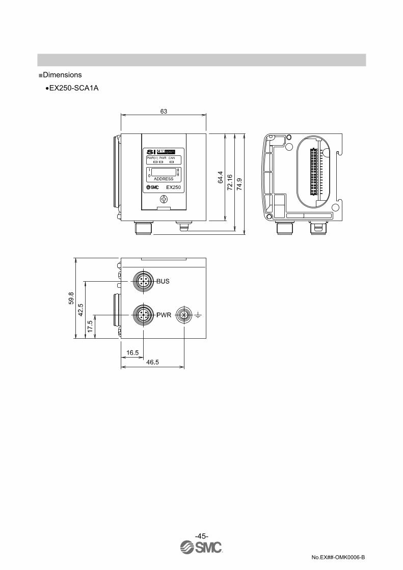
Dimensions
•EX250-SCA1A

No.EX##-OMK0006-B
Revision history A: All revised contents. B: Revision.
Note: Specifications are subject to change without prior notice and any obligation on the part of the manufacturer. © 2011 SMC Corporation All Rights Reserved