electronic data sheet specification for...
TRANSCRIPT
CAN in Automation e. V.
CANopenElectronic Data Sheet Specification
for CANopen
CiA Draft Standard Proposal 306
Version 1.0
Date: 31.05.2000

Table of Contents EDS Specification CiA
i
History
Date Changes
May 2000 Initial revision based on Appendix 12 of CiA DS-301 V3.0;
Summary of major changes:
- clarification and more detailed specification- adjustments to errata sheet and DS-302- denotation- compact storage- module concept
Table of Contents EDS Specification CiA
ii
Table of Contents
1 Scope............................................................................................................................... 1-1
2 References....................................................................................................................... 2-1
3 Definitions and Abbreviations ......................................................................................... 3-1
4 Electronic Data Sheet...................................................................................................... 4-1
4.1 Basic Structure ........................................................................................................ 4-24.2 Entry Value Interpretation........................................................................................ 4-24.3 File Information ....................................................................................................... 4-34.4 General Device Information..................................................................................... 4-44.5 Object Dictionary..................................................................................................... 4-5
4.5.1 Mapping of dummy entries........................................................................... 4-54.5.2 Object Descriptions...................................................................................... 4-64.5.3 Object Links ............................................................................................... 4-104.5.4 Comments .................................................................................................. 4-10
5 Device Configuration File DCF....................................................................................... 5-11
5.1 File Information Section........................................................................................ 5-115.2 Object Sections..................................................................................................... 5-11
5.2.1 Parameter Value in standard description ................................................... 5-115.2.2 Denotation ................................................................................................. 5-125.2.3 Compact Storage....................................................................................... 5-12
5.3 Device Commissioning .......................................................................................... 5-13
6 Module Concept ............................................................................................................. 6-14
6.1 Electronic Data Sheet ........................................................................................... 6-146.1.1 Assignment of extension modules .............................................................. 6-146.1.2 PDOs.......................................................................................................... 6-14
6.2 Module Description................................................................................................ 6-156.3 Device Configuration File...................................................................................... 6-166.4 Example ................................................................................................................ 6-17

Scope EDS Specification CiA
1-1
1 ScopeThe usage of devices in a communication network requires configuration of the deviceparameters and communication facilities. CANopen defines a standardised way toaccess these parameters via the object dictionary.
For handling of the complexity of CANopen systems Software Tools are required. Thisreduces the complexity of the planning, configuration and analysis process andsignificantly increases the security of the system.
For this purpose Software Tools need an electronic description of the CANopendevices. To allow the usage of manufacturer independent Tools, this documentdefines a standardised file format Ð called Electronic Data Sheet EDS.
Furthermore some derived file formats are specified. The DCF describes a concreteincarnation of a device configuration. The MDS describes modules of devices with amodular structure.

References EDS Specification CiA
2-1
2 References
/1/ CiA DS-301, CANopen - Application Layer and Communication Profile, Version 4.0June 1999
/2/ CiA DSP-302, Framework for Programmable CANopen Devices, Version 2.0November 1998
/3/ CiA DR-303-4, LSS Ð Layer Setting Services and Protocol, in preparation

Definitions and Abbreviations EDS Specification CiA
3-1
3 Definitions and Abbreviations
CAN Controller Area Network
CiA CAN in Automation international users and manufacturers group e.V.
COB Communication Object. (CAN Message) A unit of transportation in a CANNetwork. Data must be sent across a Network inside a COB.
COB-ID COB-Identifier. Identifies a COB uniquely in a Network. The identifierdetermines the priority of that COB in the MAC sub-layer too.
DCF Device Configuration File
DIN Deutsches Institut f�r Normung
EDS Electronic Data Sheet
ISO International Standardisation Organisation
LSS Layer Settings Specification
MDS Module Data Sheet
NMT Network Management. One of the service elements of CANopenApplication Layer in the CAN Reference Model. It performs initialisation,configuration and error handling in a CANopen network.
OSI Open Systems Interconnection
PDO Process Data Object
SDO Service Data Object
Electronic Data Sheet EDS Specification CiA
4-1
4 Electronic Data SheetIn order to give the user of a CANopen device more support the deviceÕs descriptionshould be available in a standardised way. This gives the opportunity to createstandardised tools for:
· configuration of CANopen devices,
· designing networks with CANopen devices,
· managing project information on different platforms.
Therefore two types of files are introduced to define a CANopen device withelectronically means.
An EDS can be used to describe the:
· Communication functionality and objects as defined /1/ and ApplicationFrameworks DS-3xx
· Device specific objects as defined in the device profiles DS-4XX.
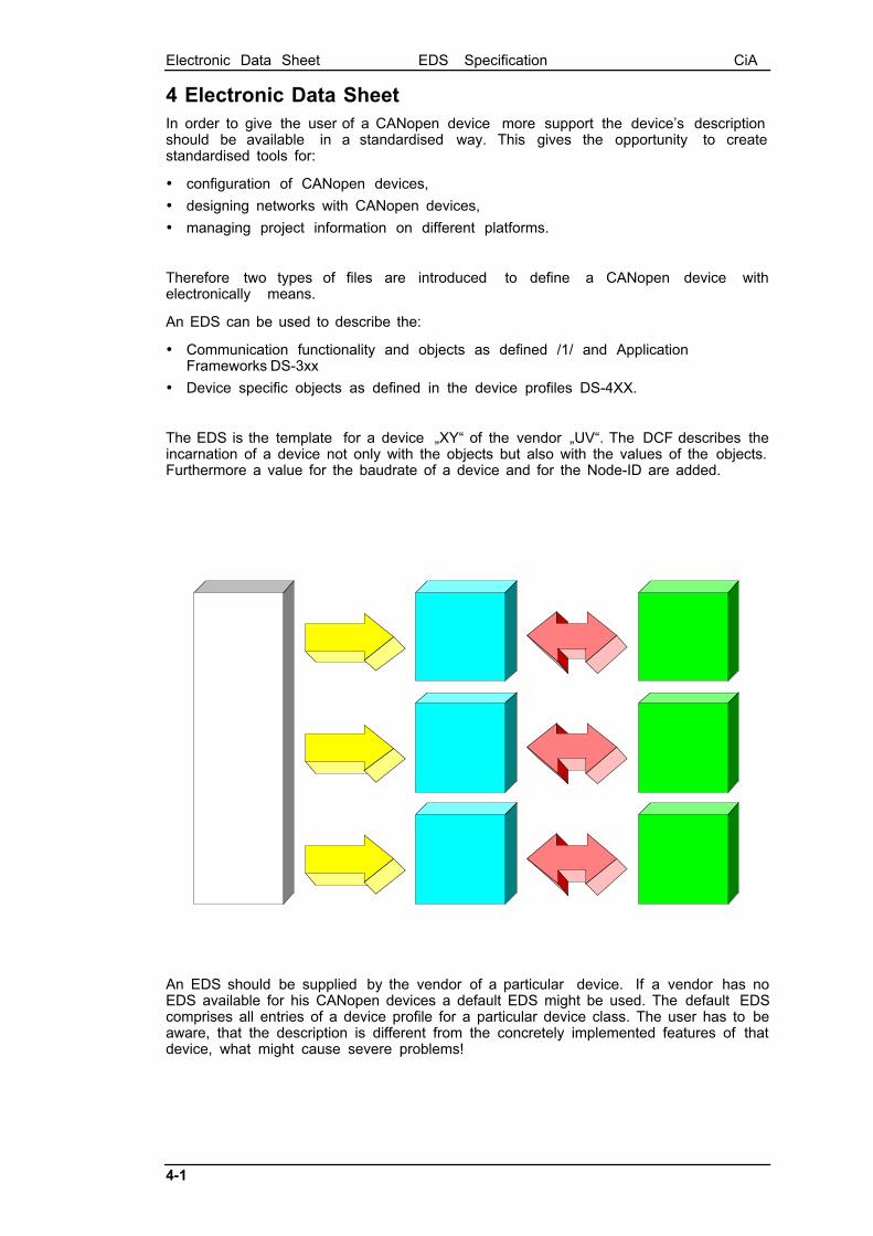
The EDS is the template for a device ãXYÒ of the vendor ãUVÒ. The DCF describes theincarnation of a device not only with the objects but also with the values of the objects.Furthermore a value for the baudrate of a device and for the Node-ID are added.
An EDS should be supplied by the vendor of a particular device. If a vendor has noEDS available for his CANopen devices a default EDS might be used. The default EDScomprises all entries of a device profile for a particular device class. The user has to beaware, that the description is different from the concretely implemented features of thatdevice, what might cause severe problems!

Electronic Data Sheet EDS Specification CiA
4-2
4.1 Basic StructureThe files are ASCII-coded, the ANSI character set shall be used.
The lines can be ended by a LF character or by a CR / LF combination. The totallength of a line must not exceed 255 characters.
The EDS contains several sections, each of which consists of a group of related entries.The sections and the entries are listed in the following format:
[section name]keyname=value
In this example, [section name] is the name of a section. The enclosing brackets ([])are required, and the left bracket must be in the leftmost column. Section names arenot case sensitive.
The keyname=value statement defines the value of each entry. A keyname is the nameof an entry. It can consist of any combination of letters and digits, and must befollowed immediately by an equal sign (=). The keyname is not case sensitive. If thekeyname consists only of digits, it is interpreted as a string, not as a number. Thismeans, that the entry 10=xxx is not the same as 0xA=xxx and 0xA=xxx is not the sameas 0x0A=.... The same applies to section names.
The value is a string, which can be interpreted depending on the entry (see below).
You can include comments and empty lines in EDS files. You must begin each line ofa comment with a semicolon (;). It must be in the leftmost column.
The sections can appear in any order inside the file. Inside each section, the entriescan appear in any order.
If not specified otherwise, all sections and entries in this paper are mandatory. In orderto support future extensions it is allowed to include additional sections and additionalentries inside the sections. Anyhow the Conformance Test Tool will recognise this withwarning messages.
4.2 Entry Value InterpretationThe interpretation of the values depends on each specific entry. Some general rulesare defined:
Leading and trailing white space is trimmed. The line
keyname=value
is interpreted the same way as
keyname= value
Integer numbers can be written as decimal numbers, hexadecimal numbers or octalnumbers. Hexadecimal numbers are preceded by 0x. Octal numbers start with aleading 0 (not followed by x). If the entry contains a number the following lines areidentical:
keyname=10keyname=0xakeyname=0x0akeyname=0xAkeyname=0x000Akeyname=012
If an entry hasnÕt a value, this is denoted by End-Of-Line after the equal sign (emptyentry). A missing entry is interpreted the same way as an entry without value.
String values are stored without quotes.
Octett Strings and raw data of domains are stored as sequence of hexadecimal bytes(without leading 0x). Bytes with a high nibble of 0 must be stored with the leading 0. Ifthe data does not fit within one line, it may be stored in a separate file (refer to chapter5.2.1).
Electronic Data Sheet EDS Specification CiA
4-3
Example for octett string:
DemoSeq=01a1053c45aabbccddeeff
Bitstrings are stored as a sequence of 0 and 1.
Example:
BitDemo=11001010000111
For entries of one of the integer types it is allowed to use a formula. This gives thechance to describe values, that depend on other values. For example, the COB-ID ofthe default PDOs depend on the Node-ID of the device.
The syntax of the formula is given by the following EBNF description:
IntEntryValue = $NODEID { Ó+Ó number }
For concrete devices, $NODEID will be replaced by the actual Node-ID of the device.The $NODEID must appear at the beginning of the expression. Otherwise the line isinterpreted as without a formula. Actually it is only possible to use an offset to thisNode-ID in the formula. More complex expressions are not allowed.
4.3 File InformationThe EDS contains information about itself. This is useful for version controlmanagement. This information is stored in the section [FileInfo].
The following keywords are used:
FileName file name (according to OS restrictions),
FileVersion actual file version (Unsigned8),
FileRevision actual file revision (Unsigned8),
EDSVersion Version of Specification (3 characters) in the Format Òx.yÓ. If theentry is missing, this is equal to Ò3.0Ó.
Description file description (max 243 characters),
CreationTime file creation time (characters in format ãhh:mm(AM|PM)Ò),
CreationDate date of file creation (characters in format ãmm-dd-yyyyÒ),
CreatedBy name or description of file creator (max 245 characters),
ModificationTime time of last modification (characters in format ãhh:mm(AM|PM)Ò),
ModificationDate date of last file modification (characters in format ãmm-dd-yyyyÒ),
ModifiedBy name or description of the modification (max 244 characters).
Example:
[FileInfo]FileName=vendor1.edsFileVersion=1FileRevision=2EDSVersion=4.0Description=EDS for simple I/O-deviceCreationTime=09:45AMCreationDate=05-15-1995CreatedBy=Zaphod BeeblebroxModificationTime=11:30PMModificationDate=08-21-1995ModifiedBy=Zaphod Beeblebrox
Electronic Data Sheet EDS Specification CiA
4-4
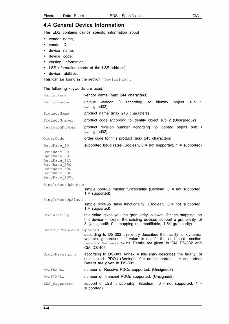
4.4 General Device InformationThe EDS contains device specific information about
· vendor name,
· vendor ID,
· device name,
· device code,
· version information,
· LSS-information (parts of the LSS-address),
· device abilities.
This can be found in the section [DeviceInfo].
The following keywords are used:
VendorName vendor name (max 244 characters)
VendorNumber unique vendor ID according to identity object sub 1(Unsigned32)
ProductName product name (max 243 characters)
ProductNumber product code according to identity object sub 2 (Unsigned32)
RevisionNumber product revision number according to identity object sub 3(Unsigned32)
OrderCode order code for this product (max 245 characters)
BaudRate_10 supported baud rates (Boolean, 0 = not supported, 1 = supported)
BaudRate_20BaudRate_50BaudRate_125BaudRate_250BaudRate_500BaudRate_800BaudRate_1000
SimpleBootUpMastersimple boot-up master functionality (Boolean, 0 = not supported,1 = supported),
SimpleBootUpSlavesimple boot-up slave functionality (Boolean, 0 = not supported,1 = supported),
Granularity this value gives you the granularity allowed for the mapping onthis device - most of the existing devices support a granularity of8 (Unsigned8; 0 - mapping not modifiable, 1-64 granularity)
DynamicChannelsSupportedaccording to DS-302 this entry describes the facility of dynamicvariable generation. If value is not 0, the additional sectionDynamicChannels exists. Details are given in CiA DS-302 andCiA DS-405.
GroupMessaging according to DS-301 Annex A this entry describes the facility ofmultiplexed PDOs. (Boolean, 0 = not supported, 1 = supported)Details are given in DS-301.
NrOfRXPDO number of Receive PDOs supported. (Unsigned8)
NrOfTXPDO number of Transmit PDOs supported. (Unsigned8)
LSS_Supported support of LSS functionality (Boolean, 0 = not supported, 1 =supported)

Electronic Data Sheet EDS Specification CiA
4-5
For compatibility reasons, the entries ProductVersion, ProductRevision,LMT_ManufacturerName, LMT_ProductName, ExtendedBootUpMaster andExtendedBootUpSlave are reserved.
Example:
[DeviceInfo]VendorName=Nepp Ltd.VendorNumber=156678ProductName=E/A 64ProductNumber=45570RevisionNumber=1OrderCode=BUY ME - 177/65/0815LSS_Supported=0BaudRate_50=1BaudRate_250=1BaudRate_500=1BaudRate_1000=1SimpleBootUpSlave=1SimpleBootUpMaster=0NrOfRxPdo=1NrOfTxPdo=2
4.5 Object DictionaryIn this logical part of the EDS the following information can be found:
1. which objects of the object dictionary are supported,
2. limit values for parameters,
3. default values.
4. data types
5. additional information
The description of the objects take place in separate parts corresponding to:
· mandatory objects,
· optional objects,
· manufacturer specific objects.
4.5.1 Mapping of dummy entries
Sometimes it is required to leave gaps in the mapping of a device. This means thate.g. a device only evaluates the last two data bytes of a PDO of 8 bytes length. The firstsix bytes should be ignored (perhaps they are evaluated by another device). In this casethe mapping of this device must contain dummy entries for these first six bytes.
The indices from the data type area of the object dictionary are used for this purpose.The user of a device has to know which data type can be used for creating dummyentries and which not (indeed only the length of the dummy object is important).
The section DummyUsage is used for describing dummies. The entries follow thisscheme:
Dummy<data type index (without 0x-prefix)>={0|1}
Example:[DummyUsage]Dummy0001=0Dummy0002=1Dummy0002=1Dummy0003=1Dummy0004=1Dummy0005=1Dummy0006=1Dummy0007=1
This means that the device will support the mapping of the data types Integer8/16/32and Unsigned8/16/32.
Electronic Data Sheet EDS Specification CiA
4-6
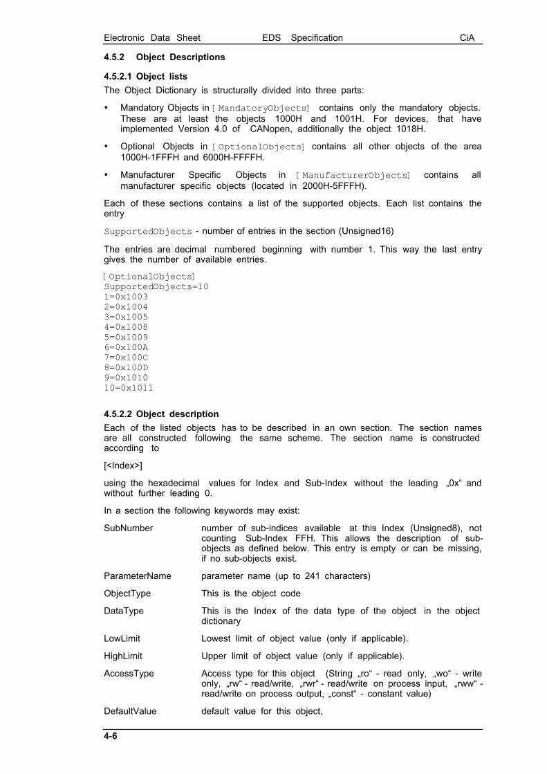
4.5.2 Object Descriptions
4.5.2.1 Object lists
The Object Dictionary is structurally divided into three parts:
· Mandatory Objects in [MandatoryObjects] contains only the mandatory objects.These are at least the objects 1000H and 1001H. For devices, that haveimplemented Version 4.0 of CANopen, additionally the object 1018H.
· Optional Objects in [OptionalObjects] contains all other objects of the area1000H-1FFFH and 6000H-FFFFH.
· Manufacturer Specific Objects in [ManufacturerObjects] contains allmanufacturer specific objects (located in 2000H-5FFFH).
Each of these sections contains a list of the supported objects. Each list contains theentry
SupportedObjects - number of entries in the section (Unsigned16)
The entries are decimal numbered beginning with number 1. This way the last entrygives the number of available entries.
[OptionalObjects]SupportedObjects=101=0x10032=0x10043=0x10054=0x10085=0x10096=0x100A7=0x100C8=0x100D9=0x101010=0x1011
4.5.2.2 Object description
Each of the listed objects has to be described in an own section. The section namesare all constructed following the same scheme. The section name is constructedaccording to
[<Index>]
using the hexadecimal values for Index and Sub-Index without the leading ã0xÒ andwithout further leading 0.
In a section the following keywords may exist:
SubNumber number of sub-indices available at this Index (Unsigned8), notcounting Sub-Index FFH. This allows the description of sub-objects as defined below. This entry is empty or can be missing,if no sub-objects exist.
ParameterName parameter name (up to 241 characters)
ObjectType This is the object code
DataType This is the Index of the data type of the object in the objectdictionary
LowLimit Lowest limit of object value (only if applicable).
HighLimit Upper limit of object value (only if applicable).
AccessType Access type for this object (String ãroÒ - read only, ãwoÒ - writeonly, ãrwÒ - read/write, ãrwrÒ - read/write on process input, ãrwwÒ -read/write on process output, ãconstÒ - constant value)
DefaultValue default value for this object,
Electronic Data Sheet EDS Specification CiA
4-7
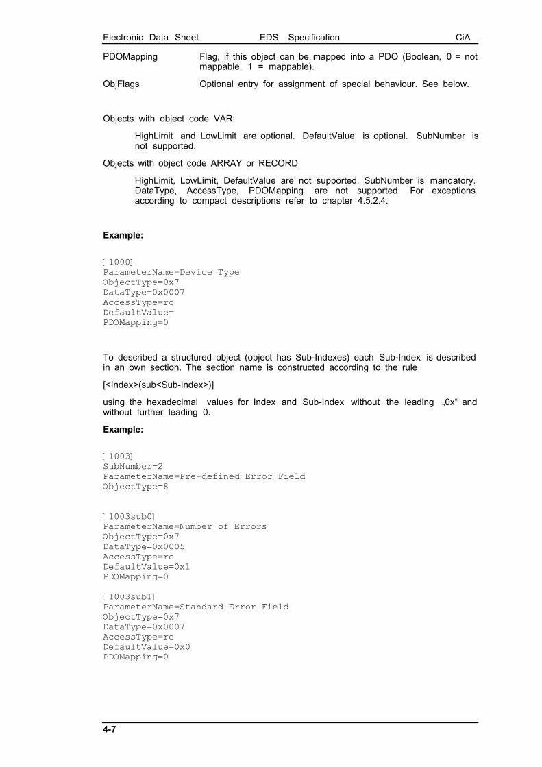
PDOMapping Flag, if this object can be mapped into a PDO (Boolean, 0 = notmappable, 1 = mappable).
ObjFlags Optional entry for assignment of special behaviour. See below.
Objects with object code VAR:
HighLimit and LowLimit are optional. DefaultValue is optional. SubNumber isnot supported.
Objects with object code ARRAY or RECORD
HighLimit, LowLimit, DefaultValue are not supported. SubNumber is mandatory.DataType, AccessType, PDOMapping are not supported. For exceptionsaccording to compact descriptions refer to chapter 4.5.2.4.
Example:
[1000]ParameterName=Device TypeObjectType=0x7DataType=0x0007AccessType=roDefaultValue=PDOMapping=0
To described a structured object (object has Sub-Indexes) each Sub-Index is describedin an own section. The section name is constructed according to the rule
[<Index>(sub<Sub-Index>)]
using the hexadecimal values for Index and Sub-Index without the leading ã0xÒ andwithout further leading 0.
Example:
[1003]SubNumber=2ParameterName=Pre-defined Error FieldObjectType=8
[1003sub0]ParameterName=Number of ErrorsObjectType=0x7DataType=0x0005AccessType=roDefaultValue=0x1PDOMapping=0
[1003sub1]ParameterName=Standard Error FieldObjectType=0x7DataType=0x0007AccessType=roDefaultValue=0x0PDOMapping=0

Electronic Data Sheet EDS Specification CiA
4-8
Application hint:
In principle it is possible, that a list of sub-object does not have consecutive Sub-Indexes. The value of Sub-Index 0 always stores the highest Sub-Index implemented.In contrast, the EDS entry SubNumber contains the number of Sub-Index implemented,including the Sub-Index 0.
Example:
[1010]SubNumber=2ParameterName=Store ParametersObjectType=8
[1010sub0]ParameterName=largest Sub-Index supportedObjectType=0x7DataType=0x0005AccessType=roDefaultValue=0x4PDOMapping=0
[1010sub4]ParameterName=save manufacturer defined parametersObjectType=0x7DataType=0x0007AccessType=roDefaultValue=0x1PDOMapping=0
4.5.2.3 Specific Flags
The entry ObjFlags allows to define a specific behaviour for Tools how to treat anobject. Example:
A typical task for a configuration software is the Download of a configured DCF file.Doing this without special recognition of special objects leads to the followingproblem: Objects such as 1010H "Store parameters" will be written with either invalidvalues or at least in an invalid order. First the objects 1000H up to 100FH are written,then "Store Parameters" and then the other parameters. This will lead toinconsistencies and is not what the user expects. One solution could be the specialtreatment of such objects by the configuration software. But even then there mayhappen the case, that device profiles or manufacturer specific objects have a similarproblem.
These special objects are marked in the EDS and DCF files. The object descriptionsections may contain an entry ObjFlags with an unsigned32 content:
The lowest bit is a boolean value (0=false, 1=true) for "Refuse write on Download", thesecond bit is a boolean value for "Refuse read on Scan", the other bits are reserved forfurther use by CiA and have to be 0.
If the entry is missing, this equals having the value 0. It is recommended to write theentry in the EDS/DCF only if it is not 0. This avoids unnecessary increase of the filesize.
4.5.2.4 Compact Storage
For devices with many objects and especially many arrays the EDS file might be verybig. The load and store process may reach unacceptable times. For this reason thefollowing definitions shall help to store the really necessary information much morecompact.
4.5.2.4.1 PDO Definitions
In principle the object descriptions for PDOs are all nearly the same. The mostimportant information is the number of TX and RX PDOs which is given by 4.4. It is
Electronic Data Sheet EDS Specification CiA
4-9
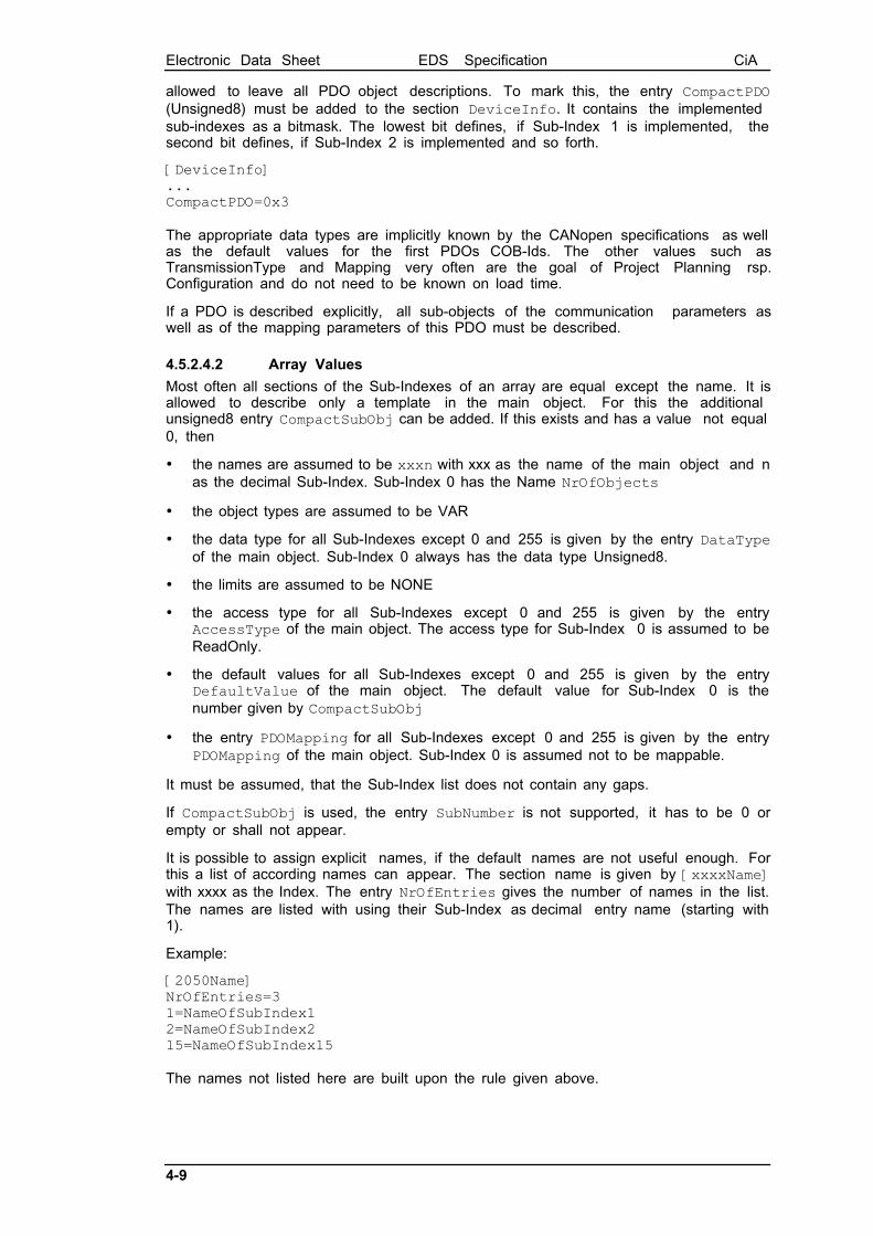
allowed to leave all PDO object descriptions. To mark this, the entry CompactPDO(Unsigned8) must be added to the section DeviceInfo. It contains the implementedsub-indexes as a bitmask. The lowest bit defines, if Sub-Index 1 is implemented, thesecond bit defines, if Sub-Index 2 is implemented and so forth.
[DeviceInfo]...CompactPDO=0x3
The appropriate data types are implicitly known by the CANopen specifications as wellas the default values for the first PDOs COB-Ids. The other values such asTransmissionType and Mapping very often are the goal of Project Planning rsp.Configuration and do not need to be known on load time.
If a PDO is described explicitly, all sub-objects of the communication parameters aswell as of the mapping parameters of this PDO must be described.
4.5.2.4.2 Array Values
Most often all sections of the Sub-Indexes of an array are equal except the name. It isallowed to describe only a template in the main object. For this the additionalunsigned8 entry CompactSubObj can be added. If this exists and has a value not equal0, then
· the names are assumed to be xxxn with xxx as the name of the main object and nas the decimal Sub-Index. Sub-Index 0 has the Name NrOfObjects
· the object types are assumed to be VAR
· the data type for all Sub-Indexes except 0 and 255 is given by the entry DataTypeof the main object. Sub-Index 0 always has the data type Unsigned8.
· the limits are assumed to be NONE
· the access type for all Sub-Indexes except 0 and 255 is given by the entryAccessType of the main object. The access type for Sub-Index 0 is assumed to beReadOnly.
· the default values for all Sub-Indexes except 0 and 255 is given by the entryDefaultValue of the main object. The default value for Sub-Index 0 is thenumber given by CompactSubObj
· the entry PDOMapping for all Sub-Indexes except 0 and 255 is given by the entryPDOMapping of the main object. Sub-Index 0 is assumed not to be mappable.
It must be assumed, that the Sub-Index list does not contain any gaps.
If CompactSubObj is used, the entry SubNumber is not supported, it has to be 0 orempty or shall not appear.
It is possible to assign explicit names, if the default names are not useful enough. Forthis a list of according names can appear. The section name is given by [xxxxName]with xxxx as the Index. The entry NrOfEntries gives the number of names in the list.The names are listed with using their Sub-Index as decimal entry name (starting with1).
Example:
[2050Name]NrOfEntries=31=NameOfSubIndex12=NameOfSubIndex215=NameOfSubIndex15
The names not listed here are built upon the rule given above.
Electronic Data Sheet EDS Specification CiA
4-10
4.5.2.4.3 Network Variables
In case of Programmable Devices according to CiA DS-302 rsp. CiA DS-405 thedescription of the dynamic network variable arrays are not written in the EDS. Allnecessary information is already given by the section DynamicChannels. To ensure aconsistent interpretation of the EDS it is not allowed to describe the dynamic networkvariable sections!
Description for Network variables, that are not treated dynamically, but are completelydescribed in the EDS, may use the CompactSubObj mechanism.
4.5.3 Object Links
In order to ease the implementation of a configuration tool it is possible to grouprelated objects together via the keyword ObjectLinks.
An object link has the following structure:
[<index>ObjectLinks]ObjectLinks=<number of available links>1=<index of 1st linked object>2=<index of 2nd linked object>3=<index of 3rd linked object>4=<index of 4th linked object>5=<index of 5th linked object>:
The list of object links is numbered decimal beginning with number 1.
Example:
; assuming we describe closed loop; this is the object ãfactorÒ[5800ObjectLinks]ObjectLinks=0x3; gain1=0x5801; zero2=0x5802; pole3=0x5803
4.5.4 Comments
Comments can be added to the EDS by using the Comments section. This section hasonly entries determining the line number and the line contents.
Lines - number of commentlines (Unsigned16)
Line<line number> - one line of comment (max 249 characters). The number isdecimal coded.
Example:
[Comments]Lines=3Line1=|-------------|Line2=| DonÕt panic |Line3=|-------------|

Device Configuration File DCF EDS Specification CiA
5-11
5 Device Configuration File DCFThe device configuration file comprises all objects for a configured device. Thedevice configuration file has the same structure as the EDS for this device. There aresome additional entries in order to describe the configured device.
5.1 File Information SectionLastEDS - file name of the EDS file used as template for this DCF
5.2 Object Sections
5.2.1 Parameter Value in standard description
ParameterValue - object value (as defined by ObjectType and DataType)
Example:
; value for object 1006 (communication cycle period)[1006]SubNumber=0ParameterName=Communication Cycle PeriodObjectType=0x7DataType=0x0007LowLimit=1000HighLimit=100000DefaultValue=20000AccessType=roParameterValue=15000PDOMapping=0
If the ObjectType is Domain (0x2) the value of the object can be stored in a file:
UploadFile: if a read access is performed for this object, the data are stored in thisfile (character 244; according to OS restrictions)
DownloadFile: if a write access is performed for this object, the data to be written canbe taken from this file (character 242; according to OS restrictions)
Example:
; manufacturer specific object 5600 (downloadable program)[5600]ParameterName=Real Good Program (RGP)ObjectType=0x2DataType=0x000FAccessType=woDownloadFile=C:\FAST\PROGRAMS\FIRST.HEX
; manufacturer specific object 5700 (core dump) [5700]ParameterName=Core Dump (CD)ObjectType=0x2DataType=0x000FAccessType=roUploadFile=C:\FAST\DEBUG\DUMPALL.HEX
Device Configuration File DCF EDS Specification CiA
5-12
5.2.2 Denotation
When using a DCF in a concrete application it is useful to assign application specificnames to the objects. This can be done by simply renaming the entry value ofParameterName. As an alternative it is possible to write the changed names into anextra entry called Denotation.
Example entry in EDS:
[6000sub1]ParameterName=Dig.Input Lines 0-7...
Example entry in DCF by changing ParameterName:
[6000sub1]ParameterName=ApplicationSpecificName1...
Example entry in DCF with Denotation:
[6000sub1]ParameterName=Dig.Input Lines 0-7Denotation=ApplicationSpecificName1...
Using the mechanism of simple renaming has the advantage of smaller file size andeasier implementation since ParameterName is mandatory and therefore alwaysavailable.
Using the entry Denotation opens the possibility of re-generation of the accordingEDS file with the original object names.
5.2.3 Compact Storage
Refer to Compact Storage of EDS in chapter 4.5.2.4. With the same background it isrequired to have the possibility of a compact storage format for the DCF files.
5.2.3.1 PDO Definitions
If the entry CompactPDO of the section DeviceInfo exists and is not 0, it is optionallyallowed to write only the Object and Sub-Object description for the concretelyconfigured PDOs. All other PDOs are disabled.
5.2.3.2 Array Values
If the entry CompactSubObj exists and has a value not equal to 0, all theParameterValues of the sub-objects are stored in an extra list. The section name isgiven by [xxxxValue] with xxxx as the Index. The entry NrOfEntries gives thenumber of entries in the list. The values are listed with using their Sub-Index asdecimal entry name (range 1-254). All missing entries in the list have a value ofDefaultValue.

Device Configuration File DCF EDS Specification CiA
5-13
Example:
[2050]SubNumber=0ParameterName=A big arrayObjectType=8DataType=0x0007AccessType=rwDefaultValue=0x0PDOMapping=0CompactSubObj=200
[2050Value]NrOfEntries=31=2002=0xab15=100
Using the same syntax it is allowed to store changed ParameterNames in an extra list.The section name is given by [xxxxDenotation] with xxxx as the Index. The entryNrOfEntries gives the number of entries in the list. The values are listed with usingtheir Sub-Index as decimal entry name (range 1-254). All missing entries in the listhave a name according to the default rule or the [xxxxName] section as described inEDS chapter 4.5.2.4.2.
5.2.3.3 Network Variable Values
Normally it is not required to configure concrete values for dynamic network variables.If there is a need to do so, the values must be stored in the standard format as given in5.2.1. The reason is, that network variable arrays might have gaps, but it is not possibleto handle gaps with the CompactSubObj mechanism.
Network variables, that are not treated dynamically (DynamicChannelsSupported=0)may be stored with the CompactSubObj mechanism.
5.3 Device CommissioningThere is an additional section in the DCF named DeviceComissioning:
NodeID deviceÕs address (Unsigned8)
NodeName node name (max 246 characters)
Baudrate deviceÕs baudrate (Unsigned16)
NetNumber number of the network (Unsigned32)
NetworkName name of the network (max 243 characters)
CANopenManager describes, if the device is the CANopen Manager. (boolean,1 = CANopen Manager, 0 or missing = not the Manager)
LSS_SerialNumber serial number according to identity object sub 4 (Unsigned32)
Example:
[DeviceComissioning]NodeID=2NodeName=DEVICE2Baudrate=1000NetNumber=42NetworkName=very important subnet in a big networkLSS_SerialNumber=9912345
Module Concept EDS Specification CiA
6-14
6 Module ConceptA very common way for building flexible devices is using a bus coupler device whichcan be extended by modules. The base device automatically detects the existence ofextension modules.
The methods commonly used are clearly structured and straight forward. Extendingsuch a device by modules leads to a varying amount of process data and configurationdata. Concerning CANopen this results in varying object dictionaries. For the extensionof process data within the object dictionary, two methods are very common.
In example for I/O modules (Profile DS-401) this is the usage of sequential Sub-Indexes. For example, the first 8 bit digital input device creates the object 6000H, 01H,the second creates object 6000H, 02H and so forth. The first digital output device workson 6200H, 01H. Additional there might be global objects that have to be created whenat least one module of a specific type is connected. For example DSP-401 defines the"Global_Interrupt_Enable" object 6423H, that may be used if at least one analogueinput is connected. Connecting further analogue inputs will not duplicate that object.
Another method is given in DS-301. There the Multi Device Module uses the approachof shifting a copy of the object dictionary structure by an offset of 800H. The first objectdictionary starts with object 6000H, the second with 6800H and so on. Object 1000Hdefines the device as Multi Device Module.
Since the combination of both mechanisms actually is not as usual in the market, thefollowing specification treats only the Sub-Index method. This keeps the specificationas compact as possible and does not exclude future extensions.
6.1 Electronic Data Sheet
6.1.1 Assignment of extension modules
The EDS of the bus coupler device contains a list of supported extension modules. Foreach type of extension module a Module Description MD describes the features of themodule. The number of the supported MD is stored in the EDS section[SupportedModules].
NrOfEntries Number of supported extension modules (Unsigned16)
6.1.2 PDOs
The pre-defined PDO mapping can be used according to the appropriate profile. Eachnew Sub-Index can be filled into the corresponding pre-defined PDO. This way up to 8byte of digital input data, 8 bytes of digital output data, 4 analogue inputs and 4analogue outputs can be mapped. Further data may be mapped to additional PDOs.Since they are not pre-defined and since their COB-IDs have to be marked as invalid,their usage has to be switched free on boot-up. In systems using the pre-definedconnection set, the application performs this task and will know the appropriate usageof the additional PDOs. In more complex systems, a configuration has to be createdthat includes configuration of the mapping. In that case the Configuration Managerhas the task of enabling all PDOs.
Using pre-defined PDOs requires the knowledge of the corresponding mapping entries.Since this mapping depends on the extension modules it can not be entered in theEDS. A generic method, that fulfils all possible cases will be very complex. To leavethis specification as simple as possible, only one rule is given:
If the EDS contains a non-empty list of extension modules, it is allowed to describemapping entries with objects, that are not necessarily existing. When the concreteconfiguration of the module is known, the mapping list is valid up to the first notexisting mapped object. The Sub-Index 0 then is shortened appropriately.
This rule will not allow to describe every case, but a wide range of practicalimplementations.
Module Concept EDS Specification CiA
6-15
Example:
The EDS of a IO bus coupler contains the following descriptions: First TPDO mappingfor objects 6000H,1 up to 6000H,8. The third TPDO for 6000H,9 up to 6000H,16. Two16 bit extension modules shall be added. Then the first TPDO will be valid. ItÕsmapping contains the entries 6000H,1 up to 6000H,4. The Sub-Index 0 is shortened to4. The third TPDO is invalid.
6.2 Module DescriptionThe module description is placed in sections of which names begin with Mx, where xis the decimal counter beginning with 1 up to the value of NrOfEntries from section[SupportedModules] without leading 0. In the following this is always abbreviatedwith Mx. Each module description has some entries in the section MxModuleInfo:
ProductName Name of the product (max 243 characters)ProductVersion Version information (Unsigned8)ProductRevision Version information (Unsigned8)OrderCode Manufacturer specific order code (max 245 characters)
A textual module description appears in the optional section [MxComments].
Lines - number of comment lines (Unsigned16)
Line<line number> - one line of comment (max 248 characters). The number isdecimal coded.
Example:
[M1Comments]Lines=2Line1=Module with 16 input linesLine2=and 8 output lines.
If required, the device has to instantiate objects on specific fixed Indexes if at least onemodule of that type is connected. These objects are described in a list in the section[MxFixedObjects]:
NrOfEntries Number of fixed objects (Unsigned16)
1=0x6423 The number N is decimal, starting with 1.2=N=...
The fixed objects are placed in sections
MxFixedxxxx.
xxxx is the hexadecimal Index without leading 0x and without any further leading 0.The contents of those sections are the same as specified for object descriptions inchapter 4.5.2.2. Sub-Objects are defined in the same way. The naming of the Sub-Object sections is
MxFixedxxxxsubx
xxxx is the hexadecimal Index without leading 0x. x is the hexadecimal Sub-Indexwithout leading 0x and without leading 0.
If several modules contain the same fixed objects, their attributes shall be equal.

Module Concept EDS Specification CiA
6-16
The section [MxSubExtends] contains a list of all objects that instantiate new Sub-Indexes.
NrOfEntries Number of extended objects (Unsigned16) followed by adecimal counted list starting with 1:
1=0x60002=...
The objects are placed in sections [MxSubExtxxxx]. xxxx is the hexadecimal Indexwithout leading 0x and without any further leading 0. In this section the same entries asin a standard object description of an EDS according to chapter 4.5.2.2 exist.Additional entries are
Count Number of extended Sub-Indexes with this description thatare created per module. The format is Unsigned8[;Unsigned8].
If one or more Sub-Indexes are created per attachedmodule to build a new sub-index, then Count is thatNumber. In example 32 bit module creates 4 Sub-Indexeseach having 8 Bit: Count=4
If several modules are gathered to form a new Sub-Index,then the number is 0, followed by semicolon and thenumber of bits that are created per module to build a newSub-Index. In example 2 bit modules with 8 bit objects:The first Sub-Index is built upon modules 1-4, the nextupon modules 5-8 etc.: Count=0;2. The objects arecreated, when a new byte begins: Module 1 creates theSub-Index 1; modules 2-4 fill it up; module 5 creates Sub-Index 2 and so forth.
ObjExtend Optional Unsigned8 entry. If an array is filled up to theend, the next object may be used. For example, in DS-401the object 6020H addresses 128 single input lines. Line129 is addressed with the next main Index 6021H.The value of this entry defines the maximum Sub-Indexafter which the next object is used. If the value is 0 or theentry is missing, the next object can not be used.
If several modules contain the same extension objects, their attributes shall be equal.
6.3 Device Configuration FileWith the information of the bus couplers EDS and the extension module descriptionsconfiguration tools are able to create the correct object dictionary and write it into theDCF. For this task no DCF specification changes are necessary.
For an easier handling it is desirable to store the information of which modules thedevice consists. This can be done by copying the section [SupportedModules] intothe DCF and then creating a reference list in the section [ConnectedModules]:
NrOfEntries Number of connected modules (Unsigned16)
1=32=3x=... x is the decimal list counter, starting with 1. The
Unsigned16 value is a reference to the[SupportedModules] list. The corresponding ModuleDescriptions can be found according to the rules of theEDS (Section names beginning with Mx, see 6.2).

Module Concept EDS Specification CiA
6-17
Example:
[SupportedModules]NrOfEntries=4
[ConnectedModules]NrOfEntries=31=22=23=4
This device has three modules connected. The first and second are described insections named with M2... , the third is described in sections named with M4...
Note: The ordering of the devices is important since this defines the assignment ofobjects to physical lines.
6.4 ExampleThe following simple example describes a base device, that can be extended bydigital input and output devices:
EXAMPLE.EDS
[FileInfo]FileName=example.eds.........
[DeviceInfo]VendorName=XYZProductName=DemoDeviceOrderCode=0..........
[SupportedModules]NrOfEntries=2
[MandatoryObjects]SupportedObjects=21=0x10002=0x1001
[1000]ParameterName=Device Type......
[OptionalObjects]SupportedObjects=81=0x10082=0x10093=0x100a4=0x10045=0x14006=0x16007=0x18008=0x1a00
.......

Module Concept EDS Specification CiA
6-18
[M1ModuleInfo]ProductName=Digital Input ModuleProductVersion=1ProductRevision=0OrderCode=DI4711
[M1SubExtends]NrOfEntries=11=0x6000
[M1SubExt6000]ParameterName=ReadState8InputLinesDataType=5DefaultValue=0PDOMapping=1AccessType=roCount=1
[M2ModuleInfo]ProductName=Digital Output ModuleProductVersion=1ProductRevision=0OrderCode=DO0815
[M2SubExtends]NrOfEntries=11=0x6200
[M2SubExt6200]ParameterName=WriteState8OutputLinesDataType=5DefaultValue=0PDOMapping=1AccessType=rwwCount=1