anywave communications corporate presentation 2016
TRANSCRIPT

1
COMMUNICATION TECHNOLOGIES CO. LTD

2
ANYWAVE Locations
USA Headquarters Lincolnshire, Illinois China Headquarters Shanghai

3
BTSIPHILIPPINES
ANYWWAVE INC.UNITED STATES OF AMERICA
PT. HANJAYA INTERNASIONALINDONESIA
BROADCAST AND STUDIO THAILAND
ANYWAVE INCCANADA
VIDEOSCOPE (MIAMI)BRAZILMEXICOCOLUMBIAARGENTINAPERUVENEZUELACHILEECUADORGUATEMALACUBAHAITIBOLIVIADOMINICAN REPUBLICHONDURASPARAGUAYEL SALVADORNICARAGUACOSTA RICAPANAMAURUGUAYGUADELOPEMARTINIQUEFRENCH GUIANA
JADE MEDIAMALAYSIA
PEOPLES MEDIA NETWORK SRI LANKA
SOUTHERN BROADCAST TECHNOLOGYVIETNAM
ESSPAKISTAN
NreachBANGLADESH
EMERGEAFGANISTAN
TECHNOMEDIAINDIA
INVERSON TECHNOLOGIESRUSSIA
INVERSON TECHNOLOGIES TAJIKISTAN
INVERSON TECHNOLOGIES KAZAKHSTAN
SERVETECHNOARMENIAGEORGIAAZERBAIJANKYRGYZSTANTURKMENISTAN
SAN YANGKOREA
ANYWAVE Representatives
Lumina Broadcast SystemsAustralia

4
ANYWAVE History 2004 Key in the development of ATSC
2006 Assisted in the development of CMMB
2007 Anywave Founded
Unique algorithms for amplifier linearization
Patents in On Channel Digital Repeaters

5
ANYWAVE Created in 2007
Originally LINX ELECTRONICS
Employees: 250+
30% of revenue spent on R&D
Anytime, Anyhow, Anywhere…

6
Originally OEM only (Exciters, Gap fillers).
In 2013 began end user direct sales.
ANYWAVEAnytime, Anyhow, Anywhere…

7
Today’s Core business:
o Exciters
o Transmitters
o Gap fillers
ANYWAVEAnytime, Anyhow, Anywhere…

8
2014 $42M annual sales
2015 $87M forecasted annual sales (93% growth)
Over 1000 transmitters or 1 Million Watts of power on back order
Over 5,000 exciters on back order
Technology innovation is DVB-T2, ATSC3.0 and ISDB-T.
Technology innovation in amplifiers with Doherty amplifier efficiencies greater than 50%.

9
Brand New State-of-the-ArtANYWAVE Manufacturing Facilities
ANYWAVE

10
Performance Best Efficiency
Unsurpassed Performance
Unequaled Value

11
ANYWAVE DohertyMore than 70% (typically)of network operators costs relate to power consumption
Most power is consumed
by the RF power amplifier devices.
Standard Class A/B design transmittersoperate with poor efficiency due to the high peak to average ratio. Typical Class A/B transmitter system efficiency is between 14-20% *
Amplifiers operate at highest efficiencyat saturation point
ANYWAVE employs DOHERTY Modulationfor improved efficiency (ℇ).
System efficiencies are improved by 50%over traditional Class A/B.

12
ANYWAVE Doherty
DOHERTY amplificationIs the most effective approach to date for efficiency improvement
The Basic idea of Doherty
Is to separate the amplification of the peak and average signal by using separate “main” and “peak” amplifiers
The resultIs a 20% or more improvement in amplifier efficiency (ℇ)

13
ANYWAVE Doherty
The MAIN PAconstantly works in saturation after reaching the “back off” point
The PEAK PA
Does not operate until the “back-off” point is reached
POWER EFFICIENCY is relatively consistant from 100% to 50% operating power
Average Power Efficiency from 100% to 50% operating level

14
Efficiency through DesignDOHERTY TECHNOLOGYmakes it possible to improve the efficiency of a broadcast amplifier
WITH COFDM (DVB-T2. ISDB-T and ATSC3.0)
efficiency increases from 20% to 40%
WITH SINGLE CARRIER SYSTEMS (ATSC 1.0)Efficiency increases from 25% to 50%
TYPICAL SAVINGS PER KILOWATT For a standard 1kW transmitter can be over $3,000 USD per year
SAVINGS Can equate to over 10% per you over the capital investment
Efficiencies are improved by 50%over traditional Class A/B.

15
Efficiency through DesignA Digital TV Transmitter has 3 key stages
- Modulator
- RF Power Amplifier
- Band Pass Filter
Modulation Amplification Filtering

16
Efficiency through DesignAN ANYWAVE AMPLIFIERTypically contains 4 or 6 Doherty pallets providing an output of 500-800W.
TYPICAL CONSUMPTION is
OFDM : 1500W (ℇ ~ 40%)
ATSC : 1200W (ℇ ~ 50%)
TAKING INTO CONSIDERATIONCombiner Losses: RF System Efficiency is reduced by 4-8%
SYSTEM EFFICIENCYIncludes modulator, cooling, control system, and AC to DC conversion
TOTAL SYSTEM EFFICIENCY~32 – 42 %Depending on Digital TV standard, ambient conditions, performance requirements and overall life expectancy

17
Powerful ADPC™ with linear and non-linear pre-correction
Dual feedback samples, before and after band pass filter
Adaptive and Automatic Correction of amplitude, phase and group delay, Thermal Memory Effects and Crest Factor Reduction
Continuous measurement and display of MER and IMD during correction
Superior non-linear pre-correction• Up to 15 dB shoulder improvements• Up to 10 dB MER (SNR) improvements
Superior linear pre-correction• In band flatness: <±0.5 dB
9X Series ExciterANYWAVE

18
Supports Analog TV (NTSC, PAL)
True real-time automatic pre-correction
Frequency Agile (VHF I, VHF III, and UHF) (9X supports entire spectrum without hardware change)
Real time measurement and display of Transmitted Signal Shoulder levels (IMD), Transmitted Signal to Noise Ratio (TSNR) and Transmitted Forward Power (FWD %)
Dual ASI or auto-switching TS Inputs provides seamless A/B input redundancy
Transport Stream over IP (optional)
9X Series Exciter
Built-in GPS receiver Built in Web Interface< -120 dBc/Hz@10 kHz offset at 473 MHz
Ultra low phase noise
ANYWAVE

19
Performance through Design Amplifier efficiency has the greatest effect on cost of
ownership, but it also has the biggest consequence on performance.
As you increase efficiency (transistors in saturation) the inherent amplifier deficiencies are increased
• Modulation Error Ratio (MER) / Signal to Noise (SNR)
• Inter-Modulation Distortion (IMD)

20
HPTV » MPTV » LPTV
ANYWAVE Products
EXCITERSENCODERS
CABLES, CONNECTORS AND FILTERS

21
ANYWAVE OFDM Products
20W – 400W
800W – 3kW
5kW – 20kW
CMMBISDBT-b

22
ANYWAVE ATSC Products
30W – 560W
1kW – 4kW
6kW – 30kW
ATSC

23
ANYWAVE Analog Products
50W – 1kW
1.5kW – 8.5kW
10kW – 50kW
PALNTSC

24
VHF
UHF
All standards (ATSC, ISDB-T, DVB-T2)
Adaptive and automatic correction
Continuous measurement of SNR/IMD
Direct Digital Up-conversion.
Measures POWER, SNR and SHOULDERS.
Full remote control via web browser.
ANYWAVE Exciters

25
Shoulder > 60 dB MER > 40dB In-band flatness < ±0.5 dB Ultra low phase noise
UNPARALLED PERFORMANCE
< -120 dBc/Hz@10 kHz offset at 473 MHz
ANYWAVE Exciters

26
ANYWAVE Translators VHF
UHF
All standards (ATSC, ISDB-T, DVB-T2)
Adaptive and automatic correction
Continuous measurement of SNR/IMD
Continuous measurement of input SNR/LEVEL.

27
ANYWAVE Amplifiers VHF
UHF
Air cooled
High efficiency
Temperature controlled fans
Self protection system
1W – 400W (OFDM) 2W - 560W (ATSC)

28
ANYWAVE LPTV Transmitters UHF (Band IV and V)
VHF (Band III)
Air cooled
High efficiency
Compact, reliable, easy to maintain
OFDM: 1W (2RU) - 400W (5RU)
ATSC: 2W (2RU) - 560W (5RU)
Analog: 5W (2RU) – 1kW (5RU)

29
ANYWAVE MPTV Transmitters UHF (Band IV and V)
VHF (Band III)
Air cooled
Doherty Modulation: High Efficiency
Easy access, installation, simple, reliable
OFDM: 800W (1270mm) - 4KW (2030 mm)
ATSC: 1kW (50”) – 3.2kW (80”)
Analog: 2kW (1270mm) - 8.5kW (2030 mm)

30
1W 2W
20W 30W
100W 140W
200W 280W
400W 560W
800W 1000W
1200W 1500W
2000W 2500W
3000W 4000W
OFDM and ATSC average transmitter power at the output of the filter.
1W to 3000W OFDM
2W to 4000W ATSC
ANYWAVE MPTV Transmitters

31
ANYWAVE HPTV Transmitters UHF (Band IV and V)
Liquid cooled
Doherty Modulation: High Efficiency
Modular
OFDM: 800W – 5.6KW (2030 mm)
ATSC: 1kW - 5kW (80”)
Analog: 2kW - 8.5kW (2030 mm)
Up to 20kW digital in multiple cabinets
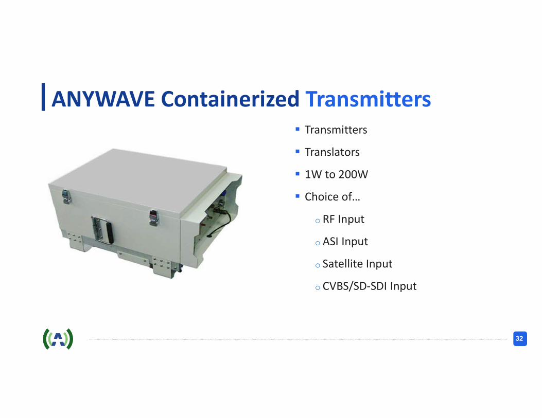
32
ANYWAVE Containerized Transmitters Transmitters
Translators
1W to 200W
Choice of…
o RF Input
oASI Input
o Satellite Input
o CVBS/SD-SDI Input

33
ANYWAVE Digital Encoders MPEG-2 / 4
SD / HD
STAT-MUX
2 – 12 Inputs
EAS Switching
Static and Dynamic PSIP

34
ANYWAVE Digital Stream Processors Manual switching between 4 incoming SDI
inputs and 4 CVBS analog-to-digital converted SDI signals into 4 SDI Outputs
Automatically switches 4 SDI Outputs to EAS signal when EAS trigger occurs, resume back to original outputs when EAS trigger stops
Provides EAS signal and EAS control signal loop-out
4 ASI Inputs into on-board Multiplexor, with program cherry picking into 2 ASI Outputs
Static & Dynamic PSIP Generator & Inserter, with auto EPG ingestion (TMS, etc.)
Provides 4 HD/SD SDI inputs, fully compliant with SDI standards
Converts the 4 CVBS inputs to SDI signals

35
ANYWAVE RF Filters & Components Filters
Combiners
Cables
Connectors

36
ANYWAVE Specialized Design Modulation
Demodulation
Correction
Encoding
Cherry picking
PSIP Editing and PSIP Generation

37
Amplifier Design
Carved in aluminum heat sink
Single piece all aluminum
All BLF888”X” devices and rejection loads are all directly mounted onto the aluminum heat sink for maximum heat dissipation and minimum heat transfer resistance
Power cables routed under the main board, within the carved heat sink
High density, heavy duty all aluminum heat sink
Light weight
Large equivalent surface area
High density panels create air flow turbulence for fast, exceptional effective heat removal
Heavy duty, speed controlled DC brushless fans
267 CFM rating for each fan
Fan speeds accessible from the control unit or via a remote access
Temperature controlled for quite operation, reduced power consumption, and extended life

38
Heavy duty, secured mounting AC input connector
Heavy duty 7/16” DIN output connectors
500 W for DVBT/ISDBT, 700 W for ATSC
High power capacity, dual 2000 W AC/DC power supplies
Total 4000 W capacity for 500 W DVBT/ISDBT, 700 W ATSC output power
Fire and smoke resistant wiring
Amplifier Design

39
Well shielded multiple compartment
All-digital bias measurement and adjustment
Dedicated Micro controller in each PA module
for local monitoring
Real time and continuous measurements on
current, voltage, bias on each BLF888A device,
temperature, forwarded power, and reflected
power levels
Amplifier Design

40
Complete monitoring and control functions
Large 5 inch touch screen
System status displayed
Forward power, reflected power, rejection power levels displayed in wattage, dBm and percentage
VSWR displayed
Driver status displayed and Input Level
Exciter presence and selection
Forward power, reflected power, current, voltage, temperature, bias voltage
Real time Log
Control SystemANYWAVE

41
Amplifier module status displayed
Fan speeds
Remote accessibility
One RS232 port
Two RS485 ports
One Ethernet (RJ45) port
Web interface
Control SystemANYWAVE

42
Installation Top mount Band Pass Filter
Space saving
Shortest possible signal path for the minimum loss
Heavy duty 1-5/8” output power feed

43
Output System
Heavy duty power combiner and directional coupler
7/16” DIN input connectors for power combining
1-5/8” output connectors for power combining
Shortest possible signal path for the minimum loss
Heavy duty direction load
With a power measurement port
800 W rated power (for 1 kW)
1-5/8” input and output for the directional coupler
Temperature controlled cooling fan
ANYWAVE
44
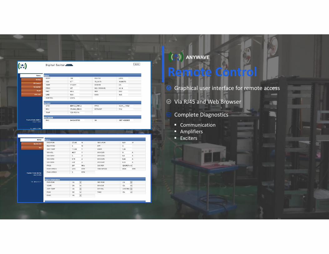
Graphical user interface for remote access
Via RJ45 and Web Browser
Complete Diagnostics
Remote Control
Communication Amplifiers Exciters
ANYWAVE

45
ANYWAVE for all your transmission needs

46
THANK YOU FOR YOUR ATTENTION
ANYWAVE
ANYWAVE COMMUNICATION TECHNOLOGIES CO. LTD
300 KNIGHTSBRIDGE PARKWAY,LINCOLNSHIRE, IL 60069-3655, USA

47
ANYWAVE
FRANK W MASSAINTERNATIONAL SALES MANAGERANYWAVE COMMUNICATION TECHNOLOGIES CO. LTD
300 KNIGHTSBRIDGE PARKWAY, 53/64 SARACHA VILLA, SANSUKLINCOLNSHIRE, IL 60069-3655, USA MUANG CHONBURI Thailand
SEND US AN [email protected]
CALL US(+66) 83 618 9333
(+1) 831 264-4159
VISIT OUR WEBSITEwww.anywavecom.com/en
For Product Inquiries, please don’t hesitate to contact us.