ap-12180 specification sheet - amstron.com · approx weight max. dis charge current internal...
TRANSCRIPT
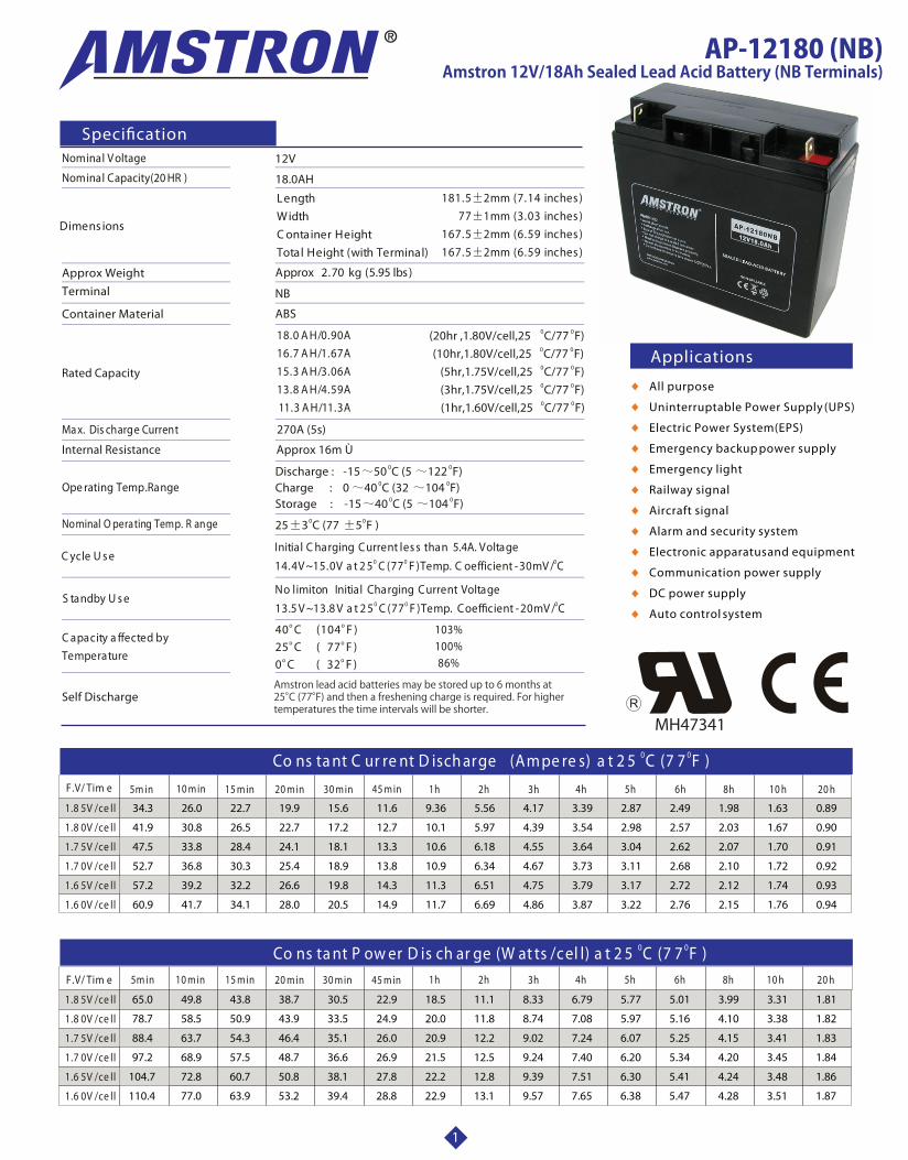
Approx Weight
Ma x. Dis charge Current
Internal Resistance
Ope rating Temp.Range
Nominal O perating Temp. R ange
Self Discharge
Terminal
Container Material
12V
Speci�cation
C ycle U s e
S tandby U s e
Initial C harging Current les s than 5.4A. Voltage 0 0 014.4V ~15.0V a t 2 5 C (77 F )Temp. C oefficient -30mV / C
No limit on Initial Charging Current Voltage 0 0 013.5 V ~13.8 V a t 2 5 C (77 F )Temp. Coef�cient - 20mV / C
C apacity a ffected by Temperature
103%100%86%
18.0AH
Rated Capacity
ABS
NB
0 025 3 C (77 5 F )
All purpose
Uninterruptable Power Supply (UPS)
Electric Power System (EPS)
Emergency backup power supply
Emergency light
Railway signal
Aircraft signal
Alarm and security system
Electronic apparatus and equipment
Communication power supply
DC power supply
Auto control system
1
o o 40 C (104 F )o o 25 C ( 77 F )
o o 0 C ( 32 F )
Applications
0 0Discharge : -15 50 C (5 122 F)00Charge : 0 40 C (32 104 F)
0 0Storage : -15 40 C (5 104 F)
Approx 2.70 kg (5.95 lbs)
Nominal Voltage
Nominal Capacity(20 HR )
Dimens ions
0 0Co ns ta nt C ur re nt D isch arge (Am pe re s) a t 2 5 C (7 7 F )
0 0Co ns ta nt P ow er D is ch ar ge (W at ts /cel l) a t 2 5 C (7 7 F )
Amstron lead acid batteries may be stored up to 6 months at 25°C (77°F) and then a freshening charge is required. For higher temperatures the time intervals will be shorter.
MH47341
AP-12180 (NB)Amstron 12V/18Ah Sealed Lead Acid Battery (NB Terminals)
LengthW idthC ontainer HeightTotal Height (with Terminal)
181.5 2mm (7.14 inches )77 1mm (3.03 inches )
167.5 2mm (6.59 inches ) 167.5 2mm (6.59 inches )
18.0 A H/0.90A16.7 A H/1.67A15.3 A H/3.06A13.8 A H/4.59A11.3 A H/11.3A
0 0(20hr ,1.80V/cell,25 C/77 F)0 0(10hr,1.80V/cell,25 C/77 F)0 0(5hr,1.75V/cell,25 C/77 F)0 0(3hr,1.75V/cell,25 C/77 F)0 0(1hr,1.60V/cell,25 C/77 F)
270A (5s)
Approx 16m Ù
3h 4h 5h 6h 8h 10 h 20 hF.V/ Tim e 5m in 10 m in 15 m in 30 m in 45 m in 1h 2h20 m in
1.8 5V /ce ll
1.8 0V /ce ll
1.7 5V /ce ll
1.7 0V /ce ll
1.6 5V /ce ll
1.6 0V /ce ll
34.3 26.0 22.7 19.9 15.6 11.6 9.36 5.56 4.17 3.39 2.87 2.49 1.98 1.63 0.89
41.9 30.8 26.5 22.7 17.2 12.7 10.1 5.97 4.39 3.54 2.98 2.57 2.03 1.67 0.90
47.5 33.8 28.4 24.1 18.1 13.3 10.6 6.18 4.55 3.64 3.04 2.62 2.07 1.70 0.91
52.7 36.8 30.3 25.4 18.9 13.8 10.9 6.34 4.67 3.73 3.11 2.68 2.10 1.72 0.92
57.2 39.2 32.2 26.6 19.8 14.3 11.3 6.51 4.75 3.79 3.17 2.72 2.12 1.74 0.93
60.9 41.7 34.1 28.0 20.5 14.9 11.7 6.69 4.86 3.87 3.22 2.76 2.15 1.76 0.94
5m in 10 m in 15 m in 30 m in 45 m in 1h 2h 3h 4h 5h 6h 8h 10 h 20 h20 m inF.V/ Tim e
1.8 5V /ce ll
1.8 0V /ce ll
1.7 5V /ce ll
1.7 0V /ce ll
1.6 5V /ce ll
1.6 0V /ce ll
65.0 49.8 43.8 38.7 30.5 22.9 18.5 11.1 8.33 6.79 5.77 5.01 3.99 3.31 1.81
78.7 58.5 50.9 43.9 33.5 24.9 20.0 11.8 8.74 7.08 5.97 5.16 4.10 3.38 1.82
88.4 63.7 54.3 46.4 35.1 26.0 20.9 12.2 9.02 7.24 6.07 5.25 4.15 3.41 1.83
97.2 68.9 57.5 48.7 36.6 26.9 21.5 12.5 9.24 7.40 6.20 5.34 4.20 3.45 1.84
104.7 72.8 60.7 50.8 38.1 27.8 22.2 12.8 9.39 7.51 6.30 5.41 4.24 3.48 1.86
110.4 77.0 63.9 53.2 39.4 28.8 22.9 13.1 9.57 7.65 6.38 5.47 4.28 3.51 1.87
2
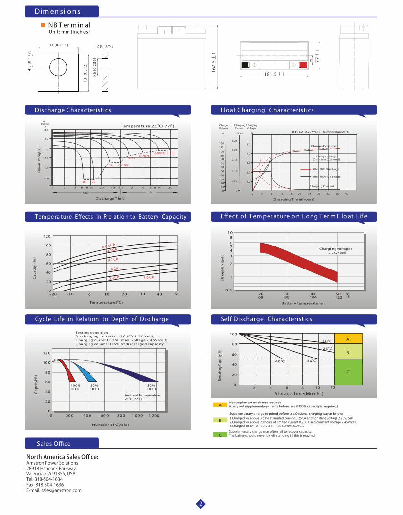
D im en si o n s
S torage Time(Months)
Rem
aining
Cap
acity
(%)
8 10 120
4 6
60
80
100
2
20
40
025 C
030 C040 C
010 C A
B
C
0.5
Batter y temperature
1
2
3
456
810
Chargi ng voltage :2.25V/ cell
2068
0C3086
40104
50122 OF
Life
expe
ctanc
y(ye
ar)
Te st ing c onditionD is ch ar ging:c urre nt 0. 17 C (F V 1. 7V /cel l);C ha rging: cu rren t 0.2 5C m ax , v oltage 2 .4 5V /cel l;C ha rging volume: 12 5% o f dis ch ar ge d c ap ac ity.
Cap
city
(%)
12 0
10 0
80
60
40
20
00 20 0 40 0 60 0 80 0 1 00 0 1 20 0
Nu mber o f C yc les
Ambient Termperature:o o25 C ( 77 F)
10 0%DO D
50 %DO D
30 %DO D
-20 -10 0 10 20 30 40 500
20
40
60
80
100
120
0.0 5C A
0.1 CA
0.2 CA
1.0 CA
2.0 CA 3.0 CA
0Temperature( C)
Cap
acity
%
Cyc le Life in Relation to Depth of Discha rge
Tem pe ra tu re E�ect s in R el at io n to Bat te ry Cap ac ity
Self Discharge Characteristics
E �ec t of T em per at u re o n L o n g T er m F lo at L if e
Sales O�ce
Float Charging Characteristics
0 8 16 2012 24 28 32 36 40
(V )(X C A)%
C hargeVolume
C harging C urrent
C harging Voltage
A fter 100% D is c harg e
C harg e Voltage(C ons tant 2.2 5v/cell)
C harg ing C urr ent
4
12.0
13.0
14.0
15.0
11.0
0.1 0
0.1 5
0.2 0
0.2 5
0.0 5
001020
30
50
40
6070
8090
100
120110
Cha rging Tim e(hours)
00.10 CA- 2.25 V/ce ll te mperature25 C
A fter 50% D is c harg e
C harged V olume
0.05C0.093C0.207C
0.4C
0.628C1C
2C3C
101 2 4 6 20 40 60 2 4 6 8 10
HMin
8 20
8.0
9.0
10.0
11.0
12.0
13.0 V
12VBattery 0 0Tem pera ture:2 5 C( 77F)
Term
inal
Vol
tage
(V)
Dis charge T ime
Discharge Characteristics
2
No supplementary charge required(Carry out supplementary charge before use if 100% capacity is required.)
Supplem entary c harge re quired before use.Optional charging way as below:
A
B
C
1.Charged for above 3 days at limited current 0.25CA and constant voltage 2.25V/cell.2.Charged for above 20 hours at limited current 0.25CA and constant voltage 2.45V/cell.3.Charged for 8~10 hours at limited current 0.05CA.
Supplementary charge may often fail to recover capacity.The battery should never be left standing till this is reached.
North America Sales Office:Amstron Power Solutions28918 Hancock Parkway,Valencia, CA 91355, USATel: 818-504-1634Fax: 818-504-1636E-mail: [email protected]
NB T er m in alUnit: mm [inch es]
14 [0.55 1] 2 [0.079 ]
4.5
[0
.17
7]
13
[0.5
12
]
6 [0
.23
6]
771
181.5 1167.
51