api 11v7 rp-gas lift valves, june 1999
DESCRIPTION
api 11vTRANSCRIPT

Recommended Practice forRepair, Testing, and Setting Gas Lift Valves
API RECOMMENDED PRACTICE 11V7SECOND EDITION, JUNE 1999


Recommended Practice forRepair, Testing, andSetting Gas Lift Valves
Upstream Segment
API RECOMMENDED PRACTICE 11V7SECOND EDITION, JUNE 1999

SPECIAL NOTES
API publications necessarily address problems of a general nature. With respect to partic-ular circumstances, local, state, and federal laws and regulations should be reviewed.
API is not undertaking to meet the duties of employers, manufacturers, or suppliers towarn and properly train and equip their employees, and others exposed, concerning healthand safety risks and precautions, nor undertaking their obligations under local, state, or fed-eral laws.
Information concerning safety and health risks and proper precautions with respect to par-ticular materials and conditions should be obtained from the employer, the manufacturer orsupplier of that material, or the material safety data sheet.
Nothing contained in any API publication is to be construed as granting any right, byimplication or otherwise, for the manufacture, sale, or use of any method, apparatus, or prod-uct covered by letters patent. Neither should anything contained in the publication be con-strued as insuring anyone against liability for infringement of letters patent.
Generally, API standards are reviewed and revised, reafÞrmed, or withdrawn at least everyÞve years. Sometimes a one-time extension of up to two years will be added to this reviewcycle. This publication will no longer be in effect Þve years after its publication date as anoperative API standard or, where an extension has been granted, upon republication. Statusof the publication can be ascertained from the API
Upstream Segment [telephone (202) 682-8000]. A catalog of API publications and materials is published annually and updated quar-terly by API, 1220 L Street, N.W., Washington, D.C. 20005.
This document was produced under API standardization procedures that ensure appropri-ate notiÞcation and participation in the developmental process and is designated as an APIstandard. Questions concerning the interpretation of the content of this standard or com-ments and questions concerning the procedures under which this standard was developedshould be directed in writing to the general manager of the Upstream Segment, AmericanPetroleum Institute, 1220 L Street, N.W., Washington, D.C. 20005. Requests for permissionto reproduce or translate all or any part of the material published herein should also beaddressed to the general manager.
API standards are published to facilitate the broad availability of proven, sound engineer-ing and operating practices. These standards are not intended to obviate the need for apply-ing sound engineering judgment regarding when and where these standards should beutilized. The formulation and publication of API standards is not intended in any way toinhibit anyone from using any other practices.
Any manufacturer marking equipment or materials in conformance with the markingrequirements of an API standard is solely responsible for complying with all the applicablerequirements of that standard. API does not represent, warrant, or guarantee that such prod-ucts do in fact conform to the applicable API standard.
All rights reserved. No part of this work may be reproduced, stored in a retrieval system, or transmitted by any means, electronic, mechanical, photocopying, recording, or otherwise,
without prior written permission from the publisher. Contact the Publisher, API Publishing Services, 1220 L Street, N.W., Washington, D.C. 20005.
Copyright © 1999 American Petroleum Institute

FOREWORD
a. This speciÞcation is under the jurisdiction of the API Subcommittee on Standardizationof Field Operative Equipment. b. American Petroleum Institute (API) Recommended Practices are published to facilitatethe broad availability of proven, sound engineering and operating practices. These Recom-mended Practices are not intended to obviate the need for applying sound judgment as towhen and where these Recommended Practices should be utilized.c. The formulation and publication of API Recommended Practices is not intended to, inany way, inhibit anyone from using any other practices.d. Any Recommended Practice may be used by anyone desiring to do so, and a diligenteffort has been made by API to assure the accuracy and reliability of the data containedherein. However, the institute makes no representation, warranty or guarantee in connectionwith the publication of any Recommended Practice and hereby expressly disclaims any lia-bility or responsibility for loss or damage resulting from its use, for any violation of anyfederal, state or municipal regulation with which an API recommendation may conßict, orfor the infringement of any patent resulting from the use of this publication.e. This Standard shall become effective on the date printed on the cover but may be usedvoluntarily from the date of distribution.
API publications may be used by anyone desiring to do so. Every effort has been made bythe Institute to assure the accuracy and reliability of the data contained in them; however, theInstitute makes no representation, warranty, or guarantee in connection with this publicationand hereby expressly disclaims any liability or responsibility for loss or damage resultingfrom its use or for the violation of any federal, state, or municipal regulation with which thispublication may conßict.
Suggested revisions are invited and should be submitted to the general manager of theUpstream Segment, American Petroleum Institute, 1220 L Street, N.W., Washington, D.C.20005.
iii


CONTENTS
Page
1 SCOPE . . . . . . . . . . . . . . . . . . . . . . . . . . . . . . . . . . . . . . . . . . . . . . . . . . . . . . . . . . . . . . . 1
2 REFERENCES . . . . . . . . . . . . . . . . . . . . . . . . . . . . . . . . . . . . . . . . . . . . . . . . . . . . . . . . 1
3 ABBREVIATIONS. . . . . . . . . . . . . . . . . . . . . . . . . . . . . . . . . . . . . . . . . . . . . . . . . . . . . 1
4 GAS LIFT VALVE DESIGNATION AND CONSTRUCTION . . . . . . . . . . . . . . . . . 14.1 Valve Designation. . . . . . . . . . . . . . . . . . . . . . . . . . . . . . . . . . . . . . . . . . . . . . . . . . 14.2 Design . . . . . . . . . . . . . . . . . . . . . . . . . . . . . . . . . . . . . . . . . . . . . . . . . . . . . . . . . . . 14.3 Material Requirements . . . . . . . . . . . . . . . . . . . . . . . . . . . . . . . . . . . . . . . . . . . . . . 14.4 Equipment Repair Terminology . . . . . . . . . . . . . . . . . . . . . . . . . . . . . . . . . . . . . . . 1
5 RECOMMENDED DISMANTLING AND REASSEMBLY OF USED GAS LIFT VALVES . . . . . . . . . . . . . . . . . . . . . . . . . . . . . . . . . . . . . . . . . . . . . . . . . . . . . . . . . . . . . 25.1 General . . . . . . . . . . . . . . . . . . . . . . . . . . . . . . . . . . . . . . . . . . . . . . . . . . . . . . . . . . 25.2 Dismantle Procedure. . . . . . . . . . . . . . . . . . . . . . . . . . . . . . . . . . . . . . . . . . . . . . . . 25.3 Reassembly Procedure . . . . . . . . . . . . . . . . . . . . . . . . . . . . . . . . . . . . . . . . . . . . . . 25.4 Bellows Replacement . . . . . . . . . . . . . . . . . . . . . . . . . . . . . . . . . . . . . . . . . . . . . . . 3
6 INSPECTION AND REASSEMBLY DATA . . . . . . . . . . . . . . . . . . . . . . . . . . . . . . . . 36.1 Source of Replacement PartsÑTerminology. . . . . . . . . . . . . . . . . . . . . . . . . . . . . 36.2 Inspection Data . . . . . . . . . . . . . . . . . . . . . . . . . . . . . . . . . . . . . . . . . . . . . . . . . . . . 36.3 Reassembly Data . . . . . . . . . . . . . . . . . . . . . . . . . . . . . . . . . . . . . . . . . . . . . . . . . . 3
7 TESTING REBUILT VALVES . . . . . . . . . . . . . . . . . . . . . . . . . . . . . . . . . . . . . . . . . . . 37.1 General . . . . . . . . . . . . . . . . . . . . . . . . . . . . . . . . . . . . . . . . . . . . . . . . . . . . . . . . . . 37.2 Valve Core. . . . . . . . . . . . . . . . . . . . . . . . . . . . . . . . . . . . . . . . . . . . . . . . . . . . . . . . 37.3 Reverse Flow (Check) Valve . . . . . . . . . . . . . . . . . . . . . . . . . . . . . . . . . . . . . . . . . 37.4 Valve Leakage Test . . . . . . . . . . . . . . . . . . . . . . . . . . . . . . . . . . . . . . . . . . . . . . . . . 47.5 Hydrostatic Aging Tests . . . . . . . . . . . . . . . . . . . . . . . . . . . . . . . . . . . . . . . . . . . . . 47.6 Valve Stem Travel Test . . . . . . . . . . . . . . . . . . . . . . . . . . . . . . . . . . . . . . . . . . . . . . 4
8 VALVE PRESSURE SETTING. . . . . . . . . . . . . . . . . . . . . . . . . . . . . . . . . . . . . . . . . . . 4
9 OPERATORÕS USE . . . . . . . . . . . . . . . . . . . . . . . . . . . . . . . . . . . . . . . . . . . . . . . . . . . . 4
APPENDIX A EXCERPTS FROM API SPEC 11V1, TESTING . . . . . . . . . . . . . . . . . . 9APPENDIX B EXCERPTS FROM API SPEC 11V1ÑTEST PROCEDURES . . . . . . . .
FOR GAS LIFT VALVES AND REVERSE FLOW VALVES . . . . . . 11
Figures1 Tag for Wellsite Data. . . . . . . . . . . . . . . . . . . . . . . . . . . . . . . . . . . . . . . . . . . . . . . . . 52 Shop Form . . . . . . . . . . . . . . . . . . . . . . . . . . . . . . . . . . . . . . . . . . . . . . . . . . . . . . . . . 62A Shop FormÑAll Valves . . . . . . . . . . . . . . . . . . . . . . . . . . . . . . . . . . . . . . . . . . . . . . 73 Reassembly and Test DataÑAll Valves . . . . . . . . . . . . . . . . . . . . . . . . . . . . . . . . . . 815 Typical Sleeve Tester. . . . . . . . . . . . . . . . . . . . . . . . . . . . . . . . . . . . . . . . . . . . . . . . 1216 Typical Encapsulated Tester . . . . . . . . . . . . . . . . . . . . . . . . . . . . . . . . . . . . . . . . . . 1317 Typical Gas Lift Valve Probe Test Fixture . . . . . . . . . . . . . . . . . . . . . . . . . . . . . . . 1319 Typical Stem and Seat Leakage Testers . . . . . . . . . . . . . . . . . . . . . . . . . . . . . . . . . 1420 Typical Stem and Seat Leakage . . . . . . . . . . . . . . . . . . . . . . . . . . . . . . . . . . . . . . . 14
v


1
Recommended Practice for Repair, Testing and Setting Gas Lift Valves
1 Scope
Recommended Practice 11V7 applies to repair, testing, andsetting gas lift valves and reverse ßow (check) valves. This isa recommended practice to present guidelines related to therepair and reuse of valves; these practices are intended toserve both repair shops and operators. API RP 11V7 refers totest procedures used in API SpeciÞcation 11V1 and Recom-mended Practice 11V2. Portions of these procedures areincluded in the appendices of this document.
The injection gas pressure operated (IPO) bellows valve isone example of a commonly repaired valve; the spring loadedproduction pressure operated (PPO) valve is also covered.Other valves, including bellows charged valves in productionpressure operated service should be repaired according to theguidelines, however specialty valves are best repaired at theoriginal manufacturerÕs shop.
2 References
APISpec 11V1
Gas Lift Valves, OriÞces, Reverse FlowValves and Dummy Valves
RP 11V2
Gas Lift Valve Performance
NACE
1
MR-01-75
SulÞde Stress Cracking Resistant MetallicMaterials for OilÞeld Service
3 Abbreviations
The following abbreviations are used in this recommendedpractice:
Pvo:
Test rack opening pressure at 60¡F.
P
VOT
:
Test rack opening pressure at speciÞed temperature (T).
IPO:
Injection pressure operated gas lift valve.
PPO:
Production pressure operated gas lift valve.
4 Gas Lift Valve Designation and Construction
4.1 VALVE DESIGNATION
The code for designation of particular gas lift valves is pre-sented in API Spec 11V1. The designation code identiÞes avalve as wireline or tubing retrievable, injection gas, spring orcombination closing force, type of valveÑproduction pres-sure operated or gas injection pressure operated, size, etc.
This basic designation code should apply to rebuilt as well asnew valves.
The rebuilder must permanently mark or etch the valvewith date (MO/YR), Pvo, port size, and their name, symbol,or trademark for valve identiÞcation The valve should bemarked using a low stress stamp or etching.
4.2 DESIGN
The gas lift valves and reverse ßow (check) valves that arerebuilt according to this Recommended Practice shouldadhere to API Spec 11V1, as applied to component inter-changeability, dimensional tolerance of components, packingdiameters of wireline retrievable devices, and methods ofattachment to provide leak free connections.
Component parts should be selected to permit interchange-ability within one type or model line. Dimensions and dimen-sional tolerances of the components of the valves to be rebuiltshould not prevent proper operation of the assembled device.
4.3 MATERIAL REQUIREMENTS
The material guidelines for metals and elastomers of thevalves to be rebuilt are found in API Spec 11V1.
For the initial valve installation in an H
2
S environment,new equipment is recommended and should comply withNACE MR-01-75. Subsequent replacement equipmentshould be rebuilt from valves whose components complywith the NACE speciÞcation. For example, the operator canuse valves which come from the original completion andspecify the components to maintain NACE compliance.
Since alloy speciÞcations in used (exchanged) valves can-not be determined without extensive metallurgical testing, allmetals should be assumed to be standard alloys of stainlesssteel or monel. Replacement parts should be made of stan-dard alloys equivalent to those provided by the original manu-facturer or as agreed between the repair shop and user.
Seats and stems are easily replaced and materials for thesecomponents can be speciÞed.
4.4 EQUIPMENT REPAIR TERMINOLOGY
4.4.1 Rebuilt to Original Equipment Specification
The terms implying restoration to Òoriginal (new) equip-ment speciÞcationsÓ shall be applied to used equipment onlywhen the replacement components match the original manu-facturerÕs speciÞcations. These speciÞcations should be avail-able to the operator (purchaser). The term shall not be appliedto valve brands and models that have been discontinued. Theintent is to prevent use of the terminology when speciÞcationsare not available for comparison.
1
NACE International, 1440 South Creek Drive, P.O. Box 218340,Houston, Texas 77218-8340.
2 API 11V7
4.4.2 Repaired Equipment per API Recommended Practice 11V7
All equipment restored according to this RecommendedPractice can be referred to as Òrepaired equipment per API RP11V7.Ó All repair facilities should have readily available writ-ten procedures for inspection, disassembly, reassembly, andtesting of gas lift equipment.
4.4.3 Cleaned and Reset
All equipment that is only cleaned and the (test rack) open-ing pressure reset shall be referred to as Òcleaned and reset.ÓEquipment in this category will not be stamped as is speciÞedin 4.1 and will not be considered repaired equipment.
5 Recommended Dismantling and Reassembly of Used Gas Lift Valves
5.1 GENERAL
The valves to be repaired according to this RecommendedPractice will have an opening pressure (Pvo) check for bel-lows condition, be cleaned in solvent, and have componentsinspected visually for replacement or repair.
All valves that are to be rebuilt must be completely disas-sembled and cleaned in a solvent bath. This should be doneregardless of the results of the initial check of the test rackopening pressure (Pvo). The following minimum proceduresshould be followed at disassembly:
5.2 DISMANTLE PROCEDURE
5.2.1
Use a donut or encapsulated tester (see Appendix B)to determine the Òas receivedÓ test rack opening pressure forcomparison with the opening pressure (Pvo) stamped on thevalve. If depressured or abnormally pressured, the valve mayneed a bellows replacement or the fault may be a leaky tailplug gasket or seal. The valve should be identiÞed on the shopform (Figure 2) and separated for special handling so therebuild technician will carefully check for bellows leakageduring the hydrostatic aging test.
At this point a preliminary check can be made on the stem-seat seal by observing if the valve will hold pressure for ashort inspection period of 5 seconds. The stem and seat willbe inspected later in the disassembly.
5.2.2
Remove the reverse ßow (check) valve housing if notremoved prior to the opening pressure (Pvo) test. Examine fordamage and replace dart or other components if required topass pressure test (7.3).
5.2.3
Remove tail plug (look for looseness or damage ifvalve Pvo was abnormal) and depressure valve, but leavevalve core installed to prevent loss of dampening ßuid and/orentry of cleaning solvent. Remove seat housing, snap ring,
seat, and bellows housing. Discard tail plug gasket, other cop-per gaskets, O-rings, snap rings, and packing.
5.2.4
This item is an additional procedure for dismantlingspring loaded valves:
Use the manufacturerÕs instructions to remove the springhousing and to relax the spring tension (no tension). Separatethe spring assembly from the bellows assembly for cleaningand visual inspection.
Visually inspect the spring and components and reject anyspring showing a fracture or crack. Inspect the tension rod fordamage to threads or to one of the lock nuts.
5.2.5
Clean the bellows subassembly with solvent andbrush to remove debris. Use caution so as not to damage thebellows. Discard bellows that are deformed, smashed, or oth-erwise damaged and changed from their permanent set.
5.2.6
Examine stem for damage and replace if necessary.Inspect seat and replace if necessary. Stem/seat componentsto be relapped should be kept together. The ball on the stemshould be approximately one-sixteenth (
1
/
16
) inch larger thanthe square edged seat. Designs other than the square edgedseat should retain the original manufacturerÕs dimensions.
Note: If stem must be removed from bellows, use caution to preventtorque on bellows.
5.2.7
Wash all parts in solvent or other cleaning agent.Visually inspect all parts for ßuid cutting, thread damage,cracks, or abrasion. Reject any damaged parts.
5.2.8
All threads should be cleaned in solvent and brushedto remove debris. Inspect for torn or galled threads. Reject ifdamaged.
5.2.9
At this point, the valve is ready for reassembly withnew O-rings snap rings, and gaskets. Lubricate all O-ringsprior to assembly with lubricant speciÞed by O-ring manufac-turer.
5.3 REASSEMBLY PROCEDURE
5.3.1
The repair shop should have a written reassemblyprocedure.
5.3.2
Use new copper gaskets, O-rings, snap rings. Uselight lubricant on all threads before assembly.
5.3.3
This item is an additional procedure for spring loadedvalves:
Apply light lubricant to the threads on the rod tensioner, andto the spring plus components. Assemble the spring and com-ponents using the written reassembly procedure for springvalves. Join the spring assembly to the bellows assembly.
If needed, use manufacturerÕs instructions to adjust stem-to-seat dimension, and proceed to join to seat assembly.

R
ECOMMENDED
P
RACTICE
FOR
R
EPAIR
, T
ESTING
,
AND
S
ETTING
G
AS
L
IFT
V
ALVES
3
5.3.4
Install new/reconditioned seat and mated stem backinto bellows assembly using thread locking compound onthreads. Avoid torque on the bellows.
5.3.5
Secure bellows assembly, bellows housing and seathousing. Remove and discard old valve core. Install newvalve core, with a minimum 2,000 psig pressure rating.
5.3.6
Reassemble the reverse ßow (check) valve housingwith new or reconditioned components.
5.4 BELLOWS REPLACEMENT
5.4.1
Bellows replacement for each and every recondi-tioned valve is not a recommended practice. However, thebellows should be changed when a failure is identiÞed.
5.4.2
If bellows replacement is needed, the bellows shouldbe identical to the original manufacturerÕs equipment and theattachment methods should be equivalent to the original man-ufacturerÕs procedure. An option is replacement of the com-plete bellows assembly with a unit from the originalequipment supplier.
5.4.3
If the bellows attachment is to be made using silversolder brazing, electric induction heating is the preferredmethod for soldering.
5.4.4
After attachment, the bellows should be leak checkedaccording to the repair shopÕs written procedures to assure aleak free connection at each end of the bellows.
5.4.5
Before replacement of the valve core, add damp-ening ßuid to bellows according to the manufacturerÕs writtenspeciÞcations, if available, or according to the repair shopÕswritten procedures. The valve should be stored in a vertical ora near-vertical inclined position to aid ßuid movement to thelower section of the bellows.
5.4.6
The bellows needs to be stabilized and set (aged); theprocedures of B.3 should be followed.
6 Inspection and Reassembly Data
6.1 SOURCE OF REPLACEMENT PARTS—TERMINOLOGY
Equipment components that are manufactured by the origi-nal supplier or licensed, authorized agent can be referred to asoriginal parts. The valve components are assumed to be origi-nal and are called ÒReusedÓ in Figure 3, the form ÒReassem-bly and Test DataÑAll Valves.Ó These components should beidentical to those used in a new valve assembly.
Equipment components that are manufactured by otherthan the original manufacturer (or authorized agent) shouldbe referred to as ÒReplaced.Ó These parts should have equiva-lent physical properties to the original part and should matchdimensionally.
Equipment components from the valve that are reworked,machined, lapped, or otherwise modiÞed dimensionallyshould be referred to as ÒReworkedÓ parts.
6.2 INSPECTION DATA
Upon speciÞc agreement between the operator and thevalve repair shop, the valves and mandrels can be inspectedwith the process beginning at the well and continuing throughto the opening pressure (Pvo) check and disassembly.
At the well, tags (Figure 1) should be provided by the oper-ator to the workover (or wireline) contractor to attach to eachvalve as it is removed. The operatorÕs representative shouldmark the tag after visually inspecting the valves.
At the repair shop the inspection procedure continues. Theinformation on each tag can be transferred to the inspectionreport form (Figure 2). The other information on the valvecondition can be added. This inspection process and the datarequired can be enhanced by both the repair shop and theoperator.
The Pvot test rack opening pressure at ambient conditions,and ambient shop temperature should be listed, valve disas-sembly can begin according to 5.2. Report condition of com-ponents on form (Figure 2).
6.3 REASSEMBLY DATA
The source of replacement parts and description related tothe source are given in 6.1.
A tag (Figure 3) should be attached, and the reassemblytechnician should identify sources of parts, according to 6.1.The reassembly procedure of 5.3 should be followed. This tagcan also be used to record the data obtained during testing.
7 Testing Rebuilt Valves
7.1 GENERAL
All rebuilt valves shall be tested according to API Spec11V1, section 4.4.1 (Appendix A in this Recommended Prac-tice) with repair shopÕs written procedures substituted forÒmanufacturerÕs written speciÞcations.Ó
7.2 VALVE CORE
Test the valve core. First, nitrogen charge the valve to aminimum of 1,000 psi. Bubble check the valve core by plac-ing a few drops of leak check (soapy water) around it andlooking for bubbles. If leaks occur, depressure bellows,remove and discard the valve core. Replace the valve core andrecheck for leaks.
7.3 REVERSE FLOW (CHECK) VALVE
The reverse ßow (check) valve should be air pressuretested according to Appendix A. If the check fails the test, the
4 API 11V7
elastomers should be replaced or metal seals lapped and thecheck should be retested.
7.4 VALVE LEAKAGE TEST
Test to be performed is identical to the Valve Leakage TestspeciÞed in API Spec 11V1. However, if leaks exceed theallowable 35 std ft/day rate, the stem and seat may be lappedtogether (and retained as a matched set) until leak is less thanthe allowed rate. Air or nitrogen should be used in testingvalves and the stem and seat should be clean and dry.
7.5 HYDROSTATIC AGING TESTS
Hydrostatic aging tests to stabilize the bellows should beaccording to Appendix B. The repair shop should have a writ-ten procedure for the bellows stabilization method.
7.6 VALVE STEM TRAVEL TEST
The assembled gas lift valve should be tested for stemtravel. This test purpose is to discover grossly mismatchedparts that might prevent or restrict stem movement. This testdoes not check stem movement caused by gas or liquid pres-sureÑonly a probe test can determine that movement.
The valve should be nitrogen charged to a minimum of 500psig. The stem should be moved by a stem lifter (head lifter)and measurement made of the stem travel. For reference, thefollowing table gives the stem travel of a fully open valvewith a ball stem
1
/
16
-inch larger than the square edged seat(oriÞce):
The tested valve stem travel should be listed on the reportform, Figure 3. Other geometries (other than the square edgedseat) should have stem travel recorded and compared to themanufacturerÕs written speciÞcations.
8 Valve Pressure Setting
Set the valve pressure using Appendix A. The repair shopshould have a written procedure for both the valve pressuresetting method and the bellows stabilization method.
If the rebuilt valve fails the shelf life pressure requirement,the valve should be disassembled and reassembled accordingto the procedure of 5.3. If failure occurs again, a new bellowsshould be installed.
9 Operator’s Use
The operator can use the reporting forms to develop a his-tory of valve failure causes. This can also serve to substantiatevalve life and frequency of workovers or wireline jobs forÒsuspectedÓ valve failures.
Port size, inches Stem travel, inches
0.1250 0.040.1875 0.070.2500 0.100.3125 0.110.3750 0.140.4375 0.190.5000 0.22
R
ECOMMENDED
P
RACTICE
FOR
R
EPAIR
, T
ESTING
,
AND
S
ETTING
G
AS
L
IFT
V
ALVES
5
Figure 1—Tag for Wellsite Data
A. Front of Tag
OPERATORWELL NAME & NO.FIELDDATE
Meas depth Valve Of (Top to bottom)
Order pulled
Mfg
Size (OD)
Model
PVO (TROP)
Clean Fouled Damaged
Gas inlet ports plugged with:
Sand
Rust
Mud
Scale
Paraffin
Cement
B. Back of Tag
Gas outlet plugged with:
Sand
Rust
Scale
Paraffin
Cement
Valve body condition:
OK Smashed Cut Bent
Top Packing: Condition
Bot Packing: Condition
Latch: Condition
Comments:
Tag filled out by
Service company
Mud

6 API 11V7
Figure 2—Shop Form
Operator
Well name and no.
Field
Date removed from wellDate inspected/tested
Meas depth Valve Of (Top to bottom)
Mfg Model
Size Port Size
Clean Fouled Damaged
Order pulled
Gas inlet ports plugged with:
Sand ScaleRust Paraffin
Mud Cement
Gas outlet plugged with:
Sand Scale
Rust Paraffin
Mud Cement
Valve body condition:
OK Smashed Cut Bent
Top Packing: Condition
Bot Packing: Condition
Latch: Condition
Original PVOTTest PVOT
PSIG at temp =
PSIG at ambient temp
°F°F
Seat/Stem:
Cut out
Ball damage
Seat deformed
Bellows:
Convolutions plugged
SmashedAbrasion
Cut
Cracked
Check:
Plugged
Elastometer failed
Spring failed
Dart condition
Cut
Comments:
Form filled out by
Service/valve repair company
Weld failure
R
ECOMMENDED
P
RACTICE
FOR
R
EPAIR
, T
ESTING
,
AND
S
ETTING
G
AS
L
IFT
V
ALVES
7
Figure 2A—Shop Form—All Valves
Operator
Well name and no.
Field
Date removed from well
1. Clean 2. Damaged 3. Plugged
Form filled out by
Service/valve repair company
Date inspected/tested
Order pulled
Meas depth
Mfg
ModelValve size, inches
Port size, inches
General condition:
List for each valve
Ports plugged with: 1. Sand 2. Scale 3. Rust 4. Paraffin 5. Mud 6. Cement
Gas inlet ports
Gas outlet ports
Valve body condition:
List for each valve
Wireline packing and latch condition:
Top packing:
Bot packing:
1. OK 2. Smashed 3. Cut 4. Bent
1. OK 2. Cut 3. Damaged 4. Missing
Latch:Pvo Check
Original Pvo, PSIG
Temp, deg F
Test PVOT, PSIG
Ambient temp, deg F
Seat/Stem: 1. Cut out 2. Ball damage 3. Seat deformed
List for each valveBellows convolutions: 1. Plugged 2. Cut 3. Smashed 4. Cracked 5. Abrasion 6. Weld
List for each valve
Check: 1. Plugged 2. Cut 3. Elastometer failed 4. Spring failed 5. Dart condition
List for each valve
Comments:

8 API 11V7
Figure 3—Reassembly and Test Data—All Valves
Operator
Well name and no.
Field
Date
Total number of valves
Valve number
Meas depth
Mfg
Model
Source of valve parts 1. Reused 2. Replaced 3. Reworked
(List source for each item)
Spring
Bellows
Stem
Seat
Check
Test rack opening pressure
Pvo, PSIG
@ deg F
Hydrostatic test
@PSIG
Dimensions and stem travel
Valve size, inches
Port size, inches
Stem travel, inches
Form filled out by
Service/valve repair company

9
APPENDIX A—EXCERPTS FROM API SPEC 11V1, TESTING
A.1 Testing
A.1.1 PRODUCTION RUN TEST
All valves shall successfully complete the followingrequirements:
A.1.1.1 Bellows Assembly Test
Each bellows assembly shall be tested in accordance withthe manufacturerÕs written speciÞcations to assure bellowsintegrity is in accordance with 4.4.1.5 and B.3.1 and B.3.2 inAppendix B of this speciÞcation.
A.1.1.2 Valve Pressure Test
Each gas lift valve shall be set and pressure tested in accor-dance with the manufacturerÕs written speciÞcations andtested in accordance with Section B3 in Appendix B.
A.1.1.3 Stem-Seat Leakage Test
Each gas lift valve shall be tested for leakage across thestem and seat in accordance with B.4 in Appendix B and themanufacturerÕs written speciÞcations. The leak shall notexceed 35 std ft
3
/day (1 std m
3
/day) when the downstreampressure on the valve is zero psig [0 kPa (ga)] and the
upstream pressure on the valve is greater than P
VCT
with thevalve in the test Þxture. (P
VCT
is deÞned in B.4.3 in AppendixB.)
A.1.1.4 Reverse Flow Valve Leakage Test
Reverse ßow valves shall be tested with air, nitrogen,helium, or other compressed gas for leakage in accordancewith the manufacturerÕs written speciÞcations. The leak shallnot exceed 35 std ft
3
/day (1 std m
3
/day) with a 100 psi (689kPa) ± 10% differential pressure across the reverse ßowvalve.
Note: For safety considerations, nonßammable gases such as theones suggested should be used for all valve testing.
A.1.1.5 Shelf Test
Before delivery to the user, each pressure charged valveshall be set with a minimum test rack opening pressure of 800psig [5516 kPa (ga)] at the manufacturerÕs speciÞed referencetemperature, the test rack opening pressure recorded, and thevalve then placed on the shelf for a minimum of 5 days. After5 days on the shelf, the set pressure of each valve shall bechecked at the manufacturerÕs reference temperature and anyvalve whose set pressure has changed more than one percentshall be rejected.


11
APPENDIX B—EXCERPTS FROM API SPEC 11V1—TEST PROCEDURES FOR GAS LIFT VALVES AND REVERSE FLOW VALVES
B.1 GeneralB.1.1 This is a mandatory appendix as applied to API RP11V7, Recommended Practice for Repair, Testing and SettingGas Lift Valves.
B.2 Apparatus
B.2.1 TEST RACK
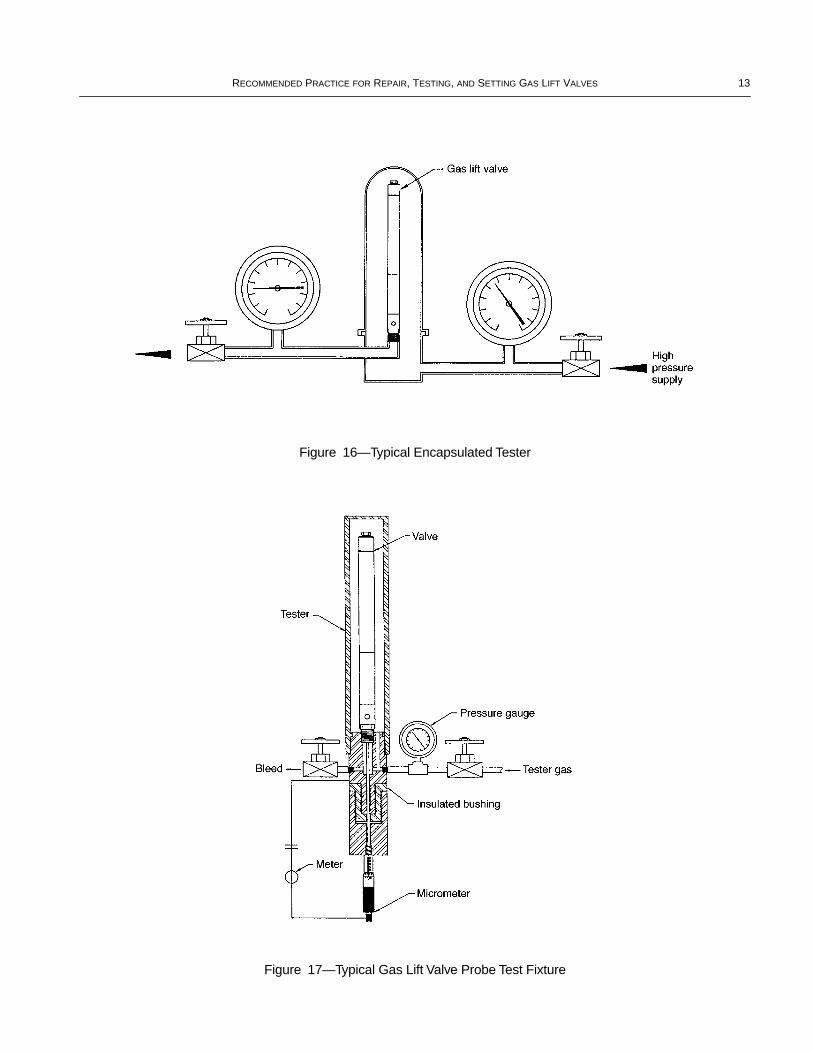
This is the equipment used to set the opening and/or clos-ing pressure of either a pressure charged or a spring loadedvalve as speciÞed by the manufacturer. There are two generaltypes in use: the ÒsleeveÓ tester (Figure 15) and the Òencapsu-latedÓ tester (Figure 16).
B.2.2 WATER BATH
This is a water-Þlled container where several gas lift valvesare immersed in the water to bring them to some predeter-mined controlled temperature. Since most gas lift installationdesigns calculate the gas lift valve set pressure at 60¡F(15.5¡C), the temperature of the water bath is usually con-trolled to 60¡F (15.5¡C). If the water temperature is otherthan 60¡F (15.5¡C), then the pressure used for setting the gaslift valve must be corrected for the temperature of the waterbath. This device is absolutely essential for pressure chargedgas lift valves. It is not needed for spring loaded valves asthey are essentially insensitive to temperature.
B.2.3 PRESSURE CHAMBER OR AGER
This device is a water Þlled chamber capable of at least5,000 psig [34.474MPa (ga)]. The gas lift valves are insertedinto the chamber and subjected to a predetermined externalpressure for some predetermined length of time and numberof cycles.
B.2.4 PROBE
This device is a micrometer to measure the stem travel aspressure is applied to the bellows. Figure 17 is a sketch of onesuch device. The rod of the probe is insulated electricallyfrom the valve. A continuity tester determines when the rodtouches the valve stem.
B.3 Valve Setting and Bellows Stabilization
B.3.1 PRESSURE CHARGED GAS LIFT VALVES
B.3.1.1 Remove the tail plugs, charge the dome to a pres-sure required by the repair shopÕs written speciÞcations. Putthe valves in the water bath for a minimum of 15 minutes.
B.3.1.2 Remove a valve from the water bath and insert it inthe tester.
CAUTION: Do not hold the valve by the dome as that willheat the dome and cause incorrect set pressure. Apply gaspressure to open the valve (test rack opening pressure). If ittakes longer than 30 seconds to measure the opening pres-sure, remove the valve from the tester and return it to thewater bath for at least 15 minutes and repeat B.3.1.2.
B.3.1.3 Install tail plugs and put all valves in the pressurechamber or ager. Bring the pressure of the changer up to agauge reading of 5,000 psig ± 100 psi [34.474 MPa (ga) ± 689kPa] and hold for a minimum of 15 minutes. Release the pres-sure and cycle the pressure to 5,000 psig ± 100 psi [34.474MPa (ga) ± 689 kPa] a minimum of three times without paus-ing more than one minute between cycles.
B.3.1.4 Remove the valves from the chamber and returnthem to the water bath for a minimum of 15 minutes.
B.3.1.5 Remove a valve from the water bath, install it inthe tester, and check the opening pressure. If the openingpressure has changed 5 psi (34.5 kPa) or more, repeat B.3.1.3through B.3.1.5 until the pressure does not change 5 psi (34.5kPa) or more.
B.3.2 SPRING LOADED GAS LIFT VALVES
B.3.2.1 Put the valve in the tester and measure the openingpressure (or closing pressure). Adjust the spring compression(tension), and check the opening pressure (or closing pres-sure). Continue until the pressure required by the manufac-turerÕs written speciÞcation is achieved.
B.3.2.2 Put the valves in the pressure chamber, bring thepressure on the chamber up to a gauge reading of 5,000 psig ±100 psi [34.474 MPa (ga) ± 689 kPa] and hold for a minimumof 15 minutes. Release the pressure and cycle the pressure to5,000 psig ± 100 psi [34.474 MPa (ga) ± 689 kPa] a mini-mum of three times without pausing more than one minutebetween cycles.
B.3.2.3 Remove the valves from the pressure chamber.Check the opening pressure (or closing pressure). If the pres-sure has changed 5 psi (34.5 kPa) or more, repeat B.3.2.2 andB.3.2.3 until the pressure does not change 5 psi (34.5 kPa) ormore.
B.4 Valve Leakage Test
B.4.1 The test rack for this test shall have provisions formeasuring low gas ßow rates on the downstream side of the

12 API 11V7
gas lift valve. Figure 19 and Figure 20 are sketches of twosuch devices.
B.4.2 This test is conducted at ambient temperatures.
B.4.3 Measure the test rack opening pressure (PVOT) atambient temperature and calculate PVCT.
PVCT = PVOT (1 Ð Ap/Ab)
where
PVCT = closing pressure of the valve at valve tempera-ture when th injection gas pressure and the pro-duction pressure are equal at the instant the valve closes in a test rack, psig [kPa (ga)],
PVOT = valve opening pressure in test rack at valve tem-perature, psig [kPa (ga)],
Ap = effective pressure area of valve stem and seat contact, in.2 (or mm2),
Ab = effective area of the bellows, in.2 (or mm2).
B.4.4 No visible oil, grease, water or other lubricating orsealing material shall be allowed on the stem and/or seat.
B.4.5 Install the valve in the Þxture, open the valve withgas pressure above PVOT, and then reduce the gas pressure toa value greater than PVCT.
B.4.6 Direct the downstream side for ßow measurement.
B.4.7 If the ßow rate is greater than 35 std ft3/day (1 stdm3/day), the stem and seat shall be rejected.
Figure 15—Typical Sleeve Tester
RECOMMENDED PRACTICE FOR REPAIR, TESTING, AND SETTING GAS LIFT VALVES 13
Figure 16—Typical Encapsulated Tester
Figure 17—Typical Gas Lift Valve Probe Test Fixture

14 API 11V7
Figure 19—Typical Stem and Seat Leakage Testers
Figure 20—Typical Stem and Seat Leakage

G11V1211V1, Gas Lift Valves, Orifices, Reverse Flow Valves and
Dummy Valves $ 70.00
Invoice To – ❏ Check here if same as “Ship To”
Company:
Name/Dept.:
Address:
City: State/Province:
Zip: Country:
Customer Daytime Telephone No.:
Fax No.:
❏ Payment Enclosed $
❏ Payment By Charge Account:❏ MasterCard ❏ Visa ❏ American Express
Account No.:
Name (As It Appears on Card):
Expiration Date:
Signature:
❏ Please Bill MeP.O. No.:
Customer Account No.:
State Sales Tax – The American Petroleum Institute is required to collect sales tax on publicationsmailed to the following states: AL, AR, CT, DC, FL, GA, IL, IN, IA, KS, KY, ME, MD, MA, MI, MN, MO, NE, NJ, NY,NC, ND, OH, PA, RI, SC, TN, TX, VT, VA, WV, and WI. Prepayment of orders shipped to these states should includeapplicable sales tax unless a purchaser is exempt. If exempt, please print your state exemption number andenclose a copy of the current exemption certificate.
Exemption Number: State:
Quantity Order Number Title Total
Subtotal
State Sales Tax (see above)
Rush Shipping Charge (see left)
Shipping and Handling (see left)
Total (in U.S. Dollars)
*To be placed on Standing Order for future editions of thispublication, place a check mark in the space provided.
Pricing and availability subject to change without notice.
Date:(Month, Day, Year)
❏ API Member(Check if Yes)API Related Publications Order Form
Ship To – (UPS will not deliver to a P.O. Box)
Company:
Name/Dept.:
Address:
City: State/Province:
Zip: Country:
Customer Daytime Telephone No.:
Fax No.:(Essential for Foreign Orders)
SO* Unit Price
Mail Orders: American Petroleum Institute, Order Desk, 1220 L Street, N.W., Washington, DC 20005-4070Fax Orders: (202) 962-4776 Phone Orders: (202) 682-8375
To better serve you, please refer to this code when ordering: L A 4 4 084 991
(Essential for Foreign Orders)
Shipping and Handling – All orders are shipped via UPS or First Class Mail in the U.S. and Canada. Ordersto all other countries will be sent by Airmail. U.S. and Canada, $5 per order handling fee, plus actual shipping costs.All other countries, for Airmail (standard service) add 25% of order value. All other countries, for UPS Next Day, addan additional 10% of order value.Rush Shipping Charge – FedEx, $10 in addition to customer providing FedEx account number:______________________________. UPS Next Day, $10 plus the actual shipping costs (1-9 items). UPSSecond Day, add $10 plus the actual shipping costs (1-9 items).Rush Bulk Orders – 1-9 items, $10. Over 9 items, add $1 each for every additional item. NOTE: Shippingon foreign orders cannot be rushed without FedEx account number.Returns Policy - Only publications received in damaged condition or as a result of shipping or processingerrors, if unstamped and otherwise not defaced, may be returned for replacement within 45 days of the initiatinginvoice date. A copy of the initiating invoice must accompany each return. Material which has neither beendamaged in shipment nor shipped in error requires prior authorization and may be subject to a shipping andhandling charge. All returns must be shipped prepaid using third class postage. If returns are dueto processing or shipping errors, API will refund the third class postage.
11V2, Gas Lift Valve Performance Testing $ 70.00G11V21
G11V52 11V5, Operation, Maintenance, and Trouble-Shooting Gas LiftInstallations
$70.00
G11V6211V6, Design of Continuous Flow Gas Lift Installations Using
Injection Pressure Operated Valve $95.00

The American Petroleum Institute provides additional resourcesand programs to industry which are based on API Standards. For more information, contact:
• Training/Workshops Ph: 202-682-8564Fax: 202-962-4797
• Inspector Certification Programs Ph: 202-682-8161Fax: 202-962-4739
• American Petroleum Institute Ph: 202-682-8574Quality Registrar Fax: 202-682-8070
• Monogram Licensing Program Ph: 202-962-4791Fax: 202-682-8070
• Engine Oil Licensing and Ph: 202-682-8233Certification System Fax: 202-962-4739
To obtain a free copy of the API Publications, Programs, and Services Catalog, call 202-682-8375 or fax your request to 202-962-4776. Or see the online interactive version of the catalog on our web site at www.api.org/cat.
Helping YouGet The JobDone Right.SM
10.1.99

5C—6/99

Additional copies available from API Publications and Distribution:(202) 682-8375
Information about API Publications, Programs and Services isavailable on the World Wide Web at: http://www.api.org
Order No. G11V72