appendix d - geotechnical exploration - alameda county government
TRANSCRIPT
........................................................................................................................
A P P E N D I X D
G E O T E C H N I C A L E X P L O R A T I O N
- Expect Excellence -
GEOTECHNICAL EXPLORATION
NEW TJ MAXX RETAIL FACILITY CASTRO VALLEY, CALIFORNIA
Submitted to:
Mr. Randall E. Nahas Nahas Company, LLC
1111 Stone Valley Road Alamo, CA 94507
Prepared by:
ENGEO Incorporated
November 12, 2012
Project No: 8876.000.001
Copyright © 2012 By ENGEO Incorporated. This Document May Not Be Reproduced In Whole Or In Part By Any Means Whatsoever, Nor May It Be Quoted Or Excerpted Without The Express Written Consent Of ENGEO Incorporated.

GEOTECHNICAL ENVIRONMENTAL
WATER RESOURCES CONSTRUCTION SERVICES
2010 Crow Canyon Place, Suite 250 San Ramon, CA 94583 (925) 866-9000 Fax (888) 279-2698 www.engeo.com
Project No. 8876.000.001
November 12, 2012 Mr. Randall E. Nahas Nahas Company, LLC 1111 Stone Valley Road Alamo, CA 94507 Subject: New TJ Maxx Retail Facility – Castro Village Shopping Center Castro Valley Boulevard Castro Valley, California GEOTECHNICAL EXPLORATION Dear Mr. Nahas: As requested, we completed this geotechnical exploration for the proposed new TJ Maxx Retail Facility at the Castro Village Shopping Center in Castro Valley, California. The accompanying report presents our field exploration and laboratory testing with our conclusions and recommendations regarding development at the site. Our findings indicate that the project site is suitable for the proposed retail facility provided the recommendations and guidelines provided in this report are implemented during project planning and construction. We are pleased to have been of service to you on this project and are prepared to consult further with you and your design team as the project progresses. Sincerely, ENGEO Incorporated Leroy Chan, PE Daniel S. Haynosch, GE lc/dsh/jf:gex

Nahas Company, LLC 8876.000.001 New TJ Maxx Retail Facility – Castro Village Shopping Center November 12, 2012
TABLE OF CONTENTS
Letter of Transmittal 1.0 INTRODUCTION ......................................................................................... 1
1.1 SITE LOCATION AND DESCRIPTION ...........................................................1 1.2 PROPOSED DEVELOPMENT ...........................................................................1 1.3 SCOPE OF SERVICES .........................................................................................1
2.0 GEOLOGY AND SEISMICITY .................................................................. 2
2.1 GEOLOGIC SETTING AND SITE GEOLOGY ...............................................2 2.2 FAULTING AND SEISMICITY ..........................................................................2 2.3 FIELD EXPLORATION.......................................................................................3 2.4 SUBSURFACE STRATIGRAPHY ......................................................................3 2.5 GROUNDWATER .................................................................................................3 2.6 LABORATORY TESTING ..................................................................................4
3.0 DISCUSSIONS ............................................................................................... 4
3.1 SEISMIC HAZARDS ............................................................................................4 3.1.1 Ground Rupture ...........................................................................................4 3.1.2 Ground Shaking ...........................................................................................4 3.1.3 Soil Liquefaction ..........................................................................................5
3.2 SULFATE EXPOSURE ........................................................................................5
4.0 RECOMMENDATIONS AND CONCLUSIONS ...................................... 7
4.1 GRADING ..............................................................................................................7 4.2 FILL PLACEMENT ..............................................................................................8 4.3 SUBGRADE TREATMENT ................................................................................8 4.4 BUILDING FOUNDATION .................................................................................9
4.4.1 Conventional Shallow Foundation System ..................................................9 4.4.1 Lateral Resistance ........................................................................................9 4.4.2 Slab-on-Grade Construction ........................................................................9 4.4.3 Secondary Slab-on-Grade Construction ....................................................10
4.5 PRELIMINARY PAVEMENT DESIGN ..........................................................11 4.6 DRAINAGE ..........................................................................................................12 4.7 UTILITIES ...........................................................................................................13
5.0 LIMITATIONS AND UNIFORMITY OF CONDITIONS ...................... 14
Nahas Company, LLC 8876.000.001 New TJ Maxx Retail Facility – Castro Village Shopping Center November 12, 2012
TABLE OF CONTENTS (Continued)
LIST OF SELECTED REFERENCES FIGURES
Figure 1 – Vicinity Map Figure 2 – Site Plan Figure 3 – Geologic Map Figure 4 – Regional Faulting and Seismicity
APPENDIX A – Boring Logs APPENDIX B – Laboratory Test Data APPENDIX C – Guide Contract Specifications

Nahas Company, LLC 8876.000.001 New TJ Maxx Retail Facility – Castro Village Shopping Center November 12, 2012
- 1 -
1.0 INTRODUCTION 1.1 SITE LOCATION AND DESCRIPTION We prepared this geotechnical exploration report for the proposed new TJ Maxx Retail Facility project located at the southwest corner of Jamison Way and Redwood Road in Castro Valley, California (Figure 1). The project site is bounded to the north by Jamison Way, existing retail shops of the Castro Village Shopping Center to the west and south, and single-story office buildings to the east. The northern portion of the project site is currently occupied by three single-family residential houses and landscape yards. The southern portion of the project site is currently occupied by an asphaltic paved parking area for the Castro Village Shopping Center. In general, the site is relatively flat with minor sloping of asphaltic pavement within the parking lot area to provide site drainage. 1.2 PROPOSED DEVELOPMENT Based on the plans for the TJ Maxx Retail Facility prepared by SGPA Architecture and Planning, dated July 18, 2012, the proposed development will include construction of a new 25,000-square-foot single-story retail structure within the northern portion of the project site and a loading dock along the eastern side of the proposed structure; associated parking areas and access roadways, landscaping areas, and new underground utilities are expected. Based on discussion with the project structural engineer, dead and live loads at the perimeter walls of up to 4.5 kips per lineal feet and interior column loads of up to 58 kips are anticipated for the retail facility. 1.3 SCOPE OF SERVICES We prepared this report as outlined in our agreement dated September 12, 2012. ENGEO’s scope of services included the following: • Conduct four exploratory test borings extending to depths of up to 41½ feet deep and collect
soil samples. • Perform laboratory testing on soil samples collected. • Analysis of the geological and geotechnical data. • Provide recommendations on mitigation measures for identified geotechnical constraints. • Preparation of this report summarizing our findings and recommendations for site
development. This report was prepared for the exclusive use of Nahas Company and its consultants for design of this project. In the event that changes are made in the character, design or layout of the development, we must be contacted to review the conclusions and recommendations contained in
Nahas Company, LLC 8876.000.001 New TJ Maxx Retail Facility – Castro Village Shopping Center November 12, 2012
- 2 -
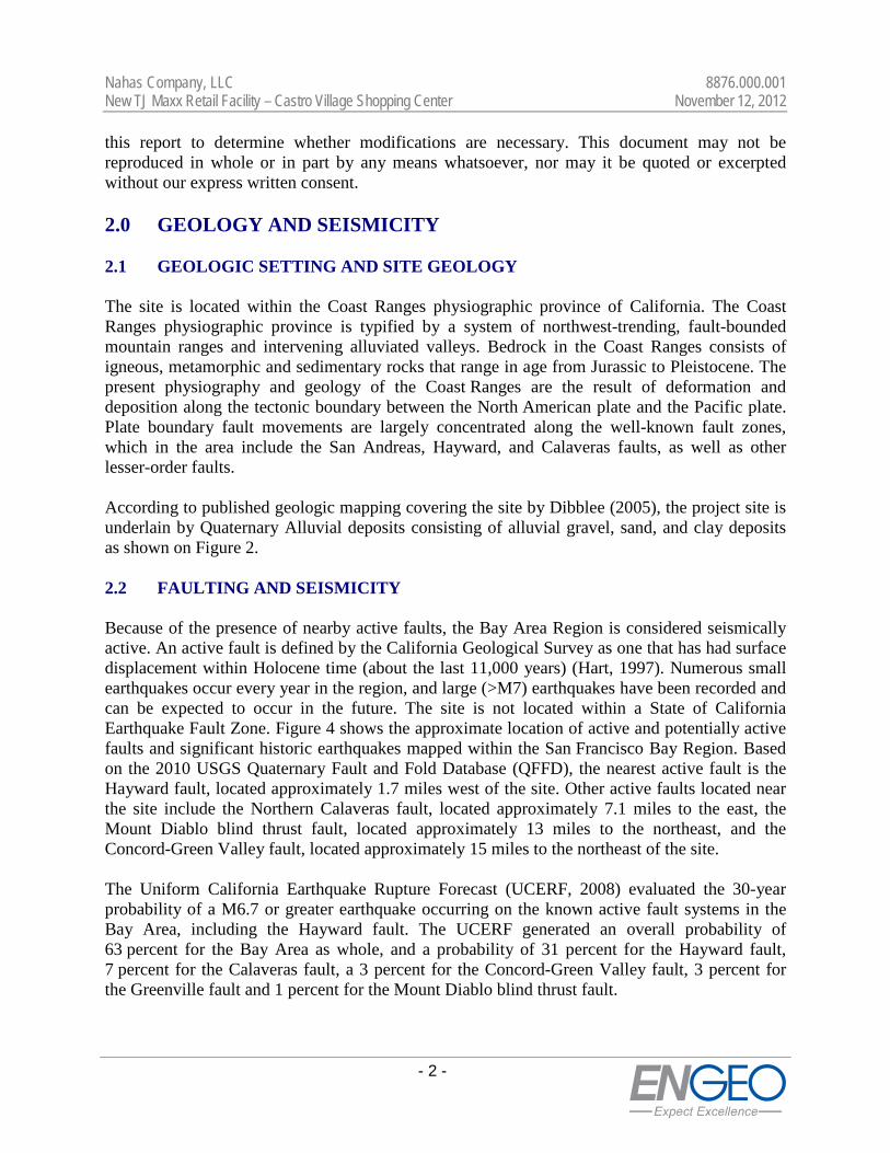
this report to determine whether modifications are necessary. This document may not be reproduced in whole or in part by any means whatsoever, nor may it be quoted or excerpted without our express written consent. 2.0 GEOLOGY AND SEISMICITY 2.1 GEOLOGIC SETTING AND SITE GEOLOGY The site is located within the Coast Ranges physiographic province of California. The Coast Ranges physiographic province is typified by a system of northwest-trending, fault-bounded mountain ranges and intervening alluviated valleys. Bedrock in the Coast Ranges consists of igneous, metamorphic and sedimentary rocks that range in age from Jurassic to Pleistocene. The present physiography and geology of the Coast Ranges are the result of deformation and deposition along the tectonic boundary between the North American plate and the Pacific plate. Plate boundary fault movements are largely concentrated along the well-known fault zones, which in the area include the San Andreas, Hayward, and Calaveras faults, as well as other lesser-order faults. According to published geologic mapping covering the site by Dibblee (2005), the project site is underlain by Quaternary Alluvial deposits consisting of alluvial gravel, sand, and clay deposits as shown on Figure 2. 2.2 FAULTING AND SEISMICITY Because of the presence of nearby active faults, the Bay Area Region is considered seismically active. An active fault is defined by the California Geological Survey as one that has had surface displacement within Holocene time (about the last 11,000 years) (Hart, 1997). Numerous small earthquakes occur every year in the region, and large (>M7) earthquakes have been recorded and can be expected to occur in the future. The site is not located within a State of California Earthquake Fault Zone. Figure 4 shows the approximate location of active and potentially active faults and significant historic earthquakes mapped within the San Francisco Bay Region. Based on the 2010 USGS Quaternary Fault and Fold Database (QFFD), the nearest active fault is the Hayward fault, located approximately 1.7 miles west of the site. Other active faults located near the site include the Northern Calaveras fault, located approximately 7.1 miles to the east, the Mount Diablo blind thrust fault, located approximately 13 miles to the northeast, and the Concord-Green Valley fault, located approximately 15 miles to the northeast of the site. The Uniform California Earthquake Rupture Forecast (UCERF, 2008) evaluated the 30-year probability of a M6.7 or greater earthquake occurring on the known active fault systems in the Bay Area, including the Hayward fault. The UCERF generated an overall probability of 63 percent for the Bay Area as whole, and a probability of 31 percent for the Hayward fault, 7 percent for the Calaveras fault, a 3 percent for the Concord-Green Valley fault, 3 percent for the Greenville fault and 1 percent for the Mount Diablo blind thrust fault.
Nahas Company, LLC 8876.000.001 New TJ Maxx Retail Facility – Castro Village Shopping Center November 12, 2012
- 3 -
2.3 FIELD EXPLORATION Our field exploration was conducted on October 23, 2012, which includes four hollow-stem auger borings. The four exploratory auger borings extended to depths of approximately 16½ to 41½ feet below existing grades at the locations shown on Figure 2. The borings were drilled using a truck-mounted drill rig equipped with hollow continuous flight augers. An ENGEO engineer logged the borings in the field and collected soil samples using either a 2½-inch-inside-diameter (I.D.) California-type split-spoon sampler fitted with 6-inch-long brass liners or a 2-inch-outside-diameter (O.D.) Standard Penetration Test (SPT) split-spoon sampler. The split-spoon samplers were driven with a 140-pound hammer falling a distance of 30 inches. The hammer was lifted with an automatic trip system. The penetration of the samplers into the soil materials was field recorded as the number of blows needed to drive the sampler 18 inches in 6-inch increments. The boring logs show the number of blows required for the last one foot of penetration, and the blow counts reported on the logs have not been converted using any correction factors. The field logs were used to develop the report boring logs presented in Appendix A. The logs of the borings depict subsurface conditions at the time the exploration was conducted. Subsurface conditions at other locations may differ from conditions occurring at these locations. Stratification lines represent the approximate boundaries between soil types and the transition may be gradual. All of the borings were backfilled on the day of drilling with cement grout under the observation and approval by a representative from the Alameda County Public Works. 2.4 SUBSURFACE STRATIGRAPHY Based on information obtained from our exploration program, the near-surface material consists of a layer of silt extending to a depth of 2½ to 3 feet below ground surface (bgs). This material may have been placed in conjunction with previous construction activities for the residential houses currently occupying the site. Test result shows that the upper layer of silt at the site has a Plasticity Index (PI) of 13, which is indicative of low expansion potential. The soil beneath the silt layer mainly consists of stiff to hard lean clays, silty clays, or sandy clays with inter-bedded layers of sandy silt to silty sand that range from 2 to 11 feet in thickness. The sandy layers have a medium dense to dense or very stiff consistency. Plasticity Indices ranging from 1 to 7 were reported for the sandy material. Below the layer of lean clay at a depth of 35 feet to 40 feet, we encountered a very stiff to hard grayish green clay with organics in all of our borings extending to a depth of up to 41½ feet. 2.5 GROUNDWATER Groundwater was encountered at a depth of between 9 to 11 feet after completion of drilling. Fluctuations in groundwater levels will occur seasonally and over a period of years because of precipitation, temperature, tidal effects, changes in drainage patterns, pumping, and/or irrigation. Based on the historically highest groundwater levels in the project area, the groundwater level at the site is mapped at contours of 10 feet deep.

Nahas Company, LLC 8876.000.001 New TJ Maxx Retail Facility – Castro Village Shopping Center November 12, 2012
- 4 -
2.6 LABORATORY TESTING Following drilling, samples were reexamined in the ENGEO laboratory to confirm field classifications. Representative driven samples were tested for the following physical characteristics:
TABLE 2.6-1 Summary of Laboratory Tests
Test Designation Location of Results
Moisture Content/Dry Density ASTM D-2216 Appendix A
Gradation ASTM D-422 Appendix B
Atterberg Limits ASTM D-4318 Appendix B
Unconfined Compression ASTM D-2166 Appendix B Laboratory test results from samples recovered are being performed at the time of this report writing. The results will be included on the boring logs in Appendix A and on the laboratory test data in Appendix B when they are complete. 3.0 DISCUSSIONS Based on a review of the findings of the subsurface exploration and laboratory test results, we conclude that the proposed retail facility and associated improvements are feasible from a geotechnical standpoint, provided that the recommendations included in this report, along with other sound engineering practices, are incorporated in the design and construction of the project. 3.1 SEISMIC HAZARDS Seismic hazards can generally be classified as primary and secondary. The potential primary seismic hazard resulting from a nearby moderate to major earthquake is ground rupture, also called surface faulting. Common secondary seismic hazards include ground shaking, soil liquefaction, liquefaction-induced settlement, dynamic densification, lateral spreading, earthquake-induced landslides, regional subsidence or uplift, and tsunamis and seiches. 3.1.1 Ground Rupture No known active faults have been mapped at the location of the proposed improvements. We therefore conclude that the potential for ground rupture is low. 3.1.2 Ground Shaking An earthquake of moderate to high magnitude generated within the San Francisco Bay Region could cause considerable ground shaking at the site.

Nahas Company, LLC 8876.000.001 New TJ Maxx Retail Facility – Castro Village Shopping Center November 12, 2012
- 5 -
To mitigate the ground shaking effects, all structures should be designed using sound engineering judgment and the latest California Building Code (CBC) requirements as a minimum. Using the USGS website Seismic Design Values for Buildings, Ground Motion Parameter Calculator, we provide the ASCE 7-05 and 2010 CBC seismic parameters in the table below.
TABLE 3.1.2-1 Seismic Design Values for Buildings
Item Design Value
Site Class D
0.2 second Spectral Response Acceleration, Ss 1.894
1.0 second Spectral Response Acceleration, S1 0.723
Site Coefficient, Fa 1.0
Site Coefficient, Fv 1.5
Maximum considered earthquake spectral response accelerations for short periods, SMS 1.894
Maximum considered earthquake spectral response accelerations for 1-second periods, SM1 1.084
Design spectral response acceleration at short periods, SDS 1.263
Design spectral response acceleration at 1-second periods, SD1 0.723 3.1.3 Soil Liquefaction Soil liquefaction is a phenomenon where saturated, cohesionless, loose soils experience a temporary, but essentially total, loss of shear strength when subjected to the reversing cyclic shear stresses caused by earthquake ground shaking. We have reviewed the map for Seismic Hazard Zones of the project area (USGS, 2003) and we have found no historical evidence of ground failure, earthquake-induced settlements or liquefaction at this site or in the general vicinity of the site. We have performed a liquefaction analysis based on the findings from the subsurface exploration assuming the groundwater level at a depth of 9 feet and we found that generally the soil under the site has a low liquefaction potential. In addition, the majority of the material encountered in our borings has sufficient fines content that is characteristic of soils that are not susceptible to liquefaction. 3.2 SULFATE EXPOSURE A representative near-surface soil material, potentially in contact with proposed foundation elements, was tested for concentration of water-soluble sulfate (SO4), in accordance with Caltrans Test Method 417. The sulfate test results are included in Appendix B. According to the laboratory testing on the near-surface soil, the sulfate ion concentration of 0.0% by weight was reported.

Nahas Company, LLC 8876.000.001 New TJ Maxx Retail Facility – Castro Village Shopping Center November 12, 2012
- 6 -
The 2010 CBC references the 2008 American Concrete Institute Manual, ACI 318 (Chapter 4, Sections 4.2 and 4.3) for concrete requirements. ACI Tables 4.2.1 and 4.3.1 provide sulfate exposure categories and classes, and concrete requirements in contact with soil based upon the exposure risk as excerpted below.
TABLE 3.2-1
ACI Table 4.2.1 - Sulfate Exposure Categories and Classes
Sulfate Exposure Category
Exposure Class (S)
Water-Soluble Sulfate in Soil
(% by Weight) Not Applicable S0 SO4 < 0.10
Moderate S1 0.10 ≤ SO4< 0.20
Severe S2 0.20 ≤ SO4 ≤ 2.00
Very Severe S3 SO4 > 2.00
TABLE 3.2-2 ACI Table 4.3.1 - Requirements for Concrete by Exposure Class
Exposure Class
Max w/cm
Min f’c (psi)
Cement Type Calcium Chloride
Admixture ASTM C150
ASTM C595
ASTM C1157
S0 N/A 2500 No Type restriction No Type restriction No Type
restriction No restriction
S1 0.5 4000 II†‡ IP(MS), IS(<70), (MS) MS No restriction
S2 0.45 4500 V‡ IP(HS), IS(<70), (HS) HS Not permitted
S3 0.45 4500 V + pozzolan or slag§
IP(HS) + pozzolan or slag or IS(<70) (HS) + pozzolan or slag§
HS + pozzolan or
slag§
Not permitted
Notes: † For seawater exposure, other types of portland cements with tricalcium aluminate (C3A) contents up to 10 percent are permitted if the w/cm does not exceed 0.40.
‡ Other available types of cement such as Type III or Type I are permitted in Exposure Classes S1 or S2 if the C3A contents are less than 8 or 5 percent, respectively.
§ The amount of the specific source of the pozzolan or slag to be used shall not be less than the amount that has been determined by service record to improve sulfate resistance when used in concrete containing Type V cement. Alternatively, the amount of the specific source of the pozzolan or slag to be used shall not be less than the amount tested in accordance with ASTM C1012 and meeting the criteria in ACI 4.5.1.
Nahas Company, LLC 8876.000.001 New TJ Maxx Retail Facility – Castro Village Shopping Center November 12, 2012
- 7 -
In accordance with the criteria presented in ACI 319-08, the test result is classified in the “Not Applicable” sulfate exposure class. Cement type and maximum water-cement ratio are not specified by the ACI for this class. As a minimum, we recommend that Type II cement be used in the concrete for the subject project. Additionally, a maximum water cement ratio of 0.50 and a minimum compressive strength of 3,000 psi are recommended for the concrete. Structural engineering requirements for strength design may result in more stringent concrete specifications. 3.3 ARTIFICIAL FILL As stated previously in the subsurface section of this report, the exploratory borings encountered a near-surface silt layer that is possibly fill placed during construction of the existing residential structures on the project site. Based on the current architectural plans, the new retail facility will be constructed in an area underlain by the silt layer. The consistency of this soil is variable and will require uniform subgrade treatment prior to foundation construction as discussed in the recommendations and conclusions section of this report. 4.0 RECOMMENDATIONS AND CONCLUSIONS The proposed project is feasible from a geotechnical engineering viewpoint provided the geotechnical recommendations in this report are properly incorporated into the design plans and specifications. If there are significant changes to the TJ Maxx retail facility including layout and grading, the recommendations presented herein may need to be refined and modified, as deemed appropriate by the Geotechnical Engineer. Geotechnical engineering recommendations contained in this report include site preparation and grading, foundation design criteria, pavements, underground utilities, and drainage. 4.1 GRADING The majority of the retail facility is located within an existing residential housing area. Grading should begin with the removal of existing structures and associated foundations, pavement, buried pipes, irrigation lines, water well systems, and any other deleterious materials. Underground pipelines and structures that will be abandoned or are expected to extend below proposed finished grades should be removed from the project site. Any organically contaminated materials should not be used in proposed building pads or pavement areas. Strip and stockpile the organics for use in landscape areas subject to the approval of the Landscape Architect or off haul. Remove any debris found within any areas to be graded. A representative of ENGEO should determine the actual removal depth in the field based on conditions encountered during the site grading. Excavations resulting from demolition and stripping below design grades should be cleaned to a firm undisturbed, non-yielding soil surface as determined by the Geotechnical Engineer. Following clearing and grubbing, scarify, moisture condition and backfill all depressions with compacted engineered fill. The requirements for
Nahas Company, LLC 8876.000.001 New TJ Maxx Retail Facility – Castro Village Shopping Center November 12, 2012
- 8 -
backfill materials and placement procedures are the same as those for engineered fill as described in the “Fill Placement” section.
Remove all existing non-engineered fill, vegetation and loose or compressible soils in areas to be graded, as necessary, for project requirements. The Geotechnical Engineer or qualified representative should determine the material removal depth in the field at the time of grading. Evaluation of unsuitable deposits should be performed during grading and may include sampling and laboratory analyses. After the site has been properly cleared and stripped, and necessary excavations have been made, scarify the surface at least 12 inches, moisture condition, and compact in accordance with the recommendations presented below in the “Fill Placement” section, prior to replacing and recompacting overlying soils as engineered fill. The compaction requirements for existing soil used for fill placement are the same as those for engineered fill, as described in a subsequent section of this report. 4.2 FILL PLACEMENT It is anticipated that site grade will remain similar to that of the existing conditions. Minor fill placement to achieve level building pads for the proposed retail facility may be performed. Areas to receive fill placement should be scarified to a minimum depth of 12 inches, moisture conditioned, and recompacted to provide adequate bonding with the initial lift of fill. All fills should be placed in thin lifts, with the lift thickness not to exceed 10 inches or the depth of penetration of the compaction equipment used, whichever is less. The following compaction control requirements should be used for general engineered fill based on non-expansive import material (PI <12): Test Procedures: ASTM D-1557. Required Moisture Content: Not less optimum moisture content. Minimum Relative Compaction: Not less than 90 percent. Relative compaction refers to the in-place dry density of soil expressed as a percentage of the maximum dry density of the same material. Additional compaction requirements may be required based on additional laboratory testing during grading. 4.3 SUBGRADE TREATMENT It is anticipated that a shallow foundation with slab-on-grade system will be used for the structure associated with the retail facility. According to our exploration data, the existing fill material has variable consistency. We recommend that the building pad and an area extending 5 feet out from the building perimeter be overexcavated a minimum of 12 inches below proposed foundation elements. The backfill should be moisture conditioned and recompacted in accordance with the specifications presented above.

Nahas Company, LLC 8876.000.001 New TJ Maxx Retail Facility – Castro Village Shopping Center November 12, 2012
- 9 -
It is important that grading work be performed under the observation of ENGEO during construction for conformance with the intent of our recommendations. 4.4 BUILDING FOUNDATION This section provides recommendations for a shallow foundation system. It is our opinion that the proposed building can be supported on conventional perimeter strip and isolated interior footing system. The final foundation plans should be provided to the Geotechnical Engineer for review before submittal to the local authority. 4.4.1 Conventional Shallow Foundation System After the completion of site stripping and the necessary pad grading, the use of continuous “strip” and isolated “column” footings are suitable for the support of the proposed building. Provided below are design criteria for typical shallow footings:
Maximum Allowable Bearing Pressure: 3,000 psf for dead plus live loads based on a Factor of Safety of 3. This value can be increased by one-third to include seismic or wind loads.
Minimum Depth of Footing: At least 18 inches below the lowest adjacent grade.
It is recommended that the shallow footings be interconnected by grade beams. Footings adjacent to utility trenches (or other footings) should bear below an imaginary 1.5:1 (horizontal:vertical) plane projected upward from the bottom edge of the utility trench (or adjacent footings). The Geotechnical Engineer should review foundation plans when they become available to check for conformance with the recommendations provided in this report.
4.4.1 Lateral Resistance Resistance to lateral loads may be provided by frictional resistance between the foundation concrete and the subgrade soils, and by passive earth pressure acting against the sides of the foundation. A coefficient of friction of 0.30 can be used between concrete and the subgrade. Passive pressures for transient loads can be taken as a uniform pressure of 300 psf. The passive resistance and base friction values include a factor of safety of about 1.5 and may be used in combination without reduction. 4.4.2 Slab-on-Grade Construction It is our understanding that concrete slabs constructed on grade will be used for the floor slabs. Slab subgrade should be prepared in accordance with recommendations provided in this report. We recommend the following for the slab construction: • Concrete slabs should be at least 6 inches thick. The slab thickness should be designed by the
Structural Engineer using a modulus of subgrade reaction of 350 pounds per square inch
Nahas Company, LLC 8876.000.001 New TJ Maxx Retail Facility – Castro Village Shopping Center November 12, 2012
- 10 -
per inch of deflection (psi/in or pci) for site soils. The slab reinforcement should be designed by the Structural Engineer. As a minimum, the slab reinforcement should consist of No. 4 bars spaced 18 inches on center each way.
• The structural engineer should be consulted on the need for a layer of sand beneath the slabs
for concrete curing purposes. • In areas where moisture migration through the slabs will be detrimental to floor coverings, a
plastic vapor retarder meeting ASTM E 1745 Class A requirements should be installed between the bottom of the slab and the layer of clean gravel or crushed rock described below.
• A layer of clean gravel or crushed rock (Section 2.04 in the Guide Contract Specifications) at
least 4 inches thick should be placed on the prepared pad subgrade.
• The pad subgrade should be moisture conditioned to a moisture content of at least 3 percentage points above optimum. The subgrade should be thoroughly soaked and approved by the Geotechnical Engineer prior to placing the reinforcement and should not be allowed to dry prior to concrete placement.
Some cracking of the slabs-on-grade should be anticipated. Frequent control joints should be provided to control the cracking. Subgrade materials should not be allowed to desiccate between grading and the construction of the concrete slabs. The floor slab subgrade should be thoroughly and uniformly presoaked prior to placing concrete. In our past experience, we have observed that concrete slabs retain moisture and may take several months to fully hydrate. The floor slab should be given sufficient time to air dry before floor coverings, such as vinyl floor tiles, are applied. Alternatively, a floor sealant could be applied over the concrete to reduce moisture from accumulating under the flooring. Also, the use of a lower water/cement ratio and higher strength concrete should reduce the amount of water in the concrete and help expedite the hydration time. 4.4.3 Secondary Slab-on-Grade Construction This section provides guidelines for secondary slabs such as exterior slabs, walkways, and steps. Secondary slabs-on-grade should be constructed structurally independent of the foundation system. This allows slab movement to occur with a reduced potential for foundation distress. Where slab-on-grade construction is anticipated, care must be exercised in attaining a near-saturation condition of the subgrade soil before concrete placement. Slabs-on-grade should be designed specifically for their intended use and loading requirements. Some of the site soils have a high expansion potential; therefore, cracking of conventional slabs should be expected. Secondary slabs-on-grade should be reinforced for control of cracking.

Nahas Company, LLC 8876.000.001 New TJ Maxx Retail Facility – Castro Village Shopping Center November 12, 2012
- 11 -
Reinforcement should be designed by the Structural Engineer. In our experience, welded wire mesh may not be sufficient to control slab cracking. As a minimum, secondary slabs-on-grade should be reinforced with No. 3 bars spaced 16 inches on center each way. Slabs-on-grade should have a minimum thickness of 4 inches. A 4-inch-thick layer of clean crushed rock or gravel should be placed under slabs. Exterior slabs should be constructed with thickened edges extending at least 6 inches into compacted soil to reduce water infiltration. Slabs should slope away from the building at a slope of at least 2 percent to prevent water from flowing toward the building. Frequent control joints should be provided to control the cracking. 4.5 PRELIMINARY PAVEMENT DESIGN The following pavement sections have been determined based on a Traffic Index of 5 and 6 and an assumed R-value of 5, and according to the method contained in Topic 608 of Highway Design Manual by Caltrans.
TABLE 4.5-1
Pavement Sections
Traffic Index HMA (inches)
Class 2 AB (inches)
5.0 3.0 10.0
6.0 3.5 13.0 Note: HMA – Hot Mix Asphalt (*City minimum thickness for public streets) AB – Caltrans Class 2 aggregate base (R-value of 78) The Traffic Index should be determined by the Civil Engineer or appropriate public agency. These sections are for estimating purposes only. Actual sections to be used should be based on R-value tests performed on samples of actual subgrade materials recovered at the time of grading. Pavement construction and all materials should comply with the requirements of the Standard Specifications of the State of California Division of Highways, City of Castro Valley requirements and the following minimum requirements. A rigid pavement section is recommended in the truck-loading dock area where the truck trailers will be parked. The recommended rigid pavement designs listed below are based on an assumed Medium Subgrade-subbase support, Axle-Load Category 3 per Portland Cement Association (PCA): • Portland Cement Concrete Pavement (PCCP) = minimum of 7.0 inches • Minimum Concrete Strength = 4,500psi • Aggregate Base (Class 2) = minimum of 6 inches

Nahas Company, LLC 8876.000.001 New TJ Maxx Retail Facility – Castro Village Shopping Center November 12, 2012
- 12 -
• Assume subgrade has an R-Value of 5. Samples of subgrade soil should be tested upon completion of subgrade preparation to verify R-Value.
• All pavement subgrades should be scarified to a depth of 12 inches below finished subgrade
elevation; moisture conditioned to at least optimum moisture content, and compacted to at least 95 percent relative compaction.
• Subgrade soils should be in a stable, non-pumping condition at the time aggregate base
materials are placed and compacted. Proof-rolling with a heavy wheel-loaded piece of construction equipment should be implemented. Yielding materials should be appropriately mitigated, with suitable mitigation measures developed in coordination with the client, contractor and Geotechnical Engineer.
• Adequate provisions must be made such that the subgrade soils and aggregate base materials
are not allowed to become saturated. • Aggregate base materials should meet current Caltrans specifications for Class 2 aggregate
base and should be compacted to at least 95 percent of maximum dry density at a moisture content of at least optimum. Proof-rolling with a heavy wheel-loaded piece of construction equipment should be implemented after placement and compaction of the aggregate base. Yielding materials should be appropriately mitigated, with suitable mitigation measures developed in coordination with the client, contractor and Geotechnical Engineer.
• Asphaltic concrete paving materials should meet current Caltrans specifications. • Ideally, concrete curbs separating pavement and irrigated landscaped areas should extend
into the subgrade and below the bottom of adjacent aggregate base materials. A back of curb drain could also be considered to help collect and mitigate subsurface seepage.
4.6 DRAINAGE The site must be positively graded at all times to provide for rapid removal of surface water runoff from the foundation systems and to prevent ponding of water under floors or seepage toward the foundation systems at any time during or after construction. Ponded water will cause undesirable soil swell and loss of strength. Ponding of stormwater must not be permitted on the property during prolonged periods of inclement weather. As a minimum requirement, finished grades should have slopes of at least 3 to 5 percent (2 percent for paved areas) within 7 feet of the exterior building walls and at right angles to them to allow surface water to drain positively away from the structure. All surface water should be collected and discharged into the storm drain system. Landscape mounds must not interfere with this requirement.

Nahas Company, LLC 8876.000.001 New TJ Maxx Retail Facility – Castro Village Shopping Center November 12, 2012
- 13 -
All roof stormwater should be collected and directed to downspouts. Stormwater from roof downspouts should be directed to a solid pipe that discharges to the street or approved drainage structure. 4.7 UTILITIES It is recommended that utility trench backfilling be done under the observation of a Geotechnical Engineer. Pipe zone backfill (i.e. material beneath and immediately surrounding the pipe) may consist of a well-graded import or native material less than ¾ inch in maximum dimension compacted in accordance with recommendations provided above for engineered fill. Trench zone backfill (i.e. material placed between the pipe zone backfill and the ground surface) may consist of native soil compacted in accordance with recommendations for engineered fill. Where import material is used for pipe zone backfill, we recommend it consist of fine- to medium-grained sand or a well-graded mixture of sand and gravel and that this material not be used within 2 feet of finish grades. In general, uniformly graded gravel should not be used for pipe or trench zone backfill due to the potential for migration of: (1) soil into the relatively large void spaces present in this type of material, and (2) water along trenches backfilled with this type of material. All utility trenches entering buildings and paved areas must be provided with an impervious seal consisting of native materials or concrete where the trenches pass under the building perimeter or curb lines. The impervious plug should extend at least 3 feet to each side of the crossing. This is to prevent surface water percolation into the sands under foundations and pavements where such water would remain trapped in a perched condition, allowing clays to develop to their full expansion potential. Care should be exercised where utility trenches are located beside foundation areas. Utility trenches constructed parallel to foundations should be located entirely above a plane extending down from the lower edge of the footing at an angle of 45 degrees. Utility trenches in areas to be paved should be constructed in accordance with City of Castro Valley requirements. Compaction of trench backfill by jetting should not be allowed at this site. If there appears to be a conflict between City or other agency requirements and the recommendations contained in this report, this should be brought to the Owner’s attention for resolution prior to submitting bids.

Nahas Company, LLC 8876.000.001 New TJ Maxx Retail Facility – Castro Village Shopping Center November 12, 2012
- 14 -
5.0 LIMITATIONS AND UNIFORMITY OF CONDITIONS This report is issued with the understanding that it is the responsibility of the owner to transmit the information and recommendations of this report to developers, owners, buyers, architects, engineers, and designers for the project so that the necessary steps can be taken by the contractors and subcontractors to carry out such recommendations in the field. The conclusions and recommendations contained in this report are solely professional opinions. The professional staff of ENGEO Incorporated strives to perform its services in a proper and professional manner with reasonable care and competence but is not infallible. There are risks of earth movement and property damages inherent in land development. We are unable to eliminate all risks or provide insurance; therefore, we are unable to guarantee or warrant the results of our services. This report is based upon field and other conditions available at the time of preparation of ENGEO's report. This document must not be subject to unauthorized reuse, that is, reuse without written authorization of ENGEO. Such authorization is essential because it requires ENGEO to evaluate the document's applicability given new circumstances, not the least of which is passage of time. If actual field or other conditions necessitate clarifications, adjustments, modifications or other changes to ENGEO's documents, ENGEO must be engaged to prepare the necessary clarifications, adjustments, modifications or other changes before construction activities commence or further activity proceeds. If ENGEO's scope of services does not include onsite construction observation, or if other persons or entities are retained to provide such services, ENGEO cannot be held responsible for any or all claims arising from or resulting from the performance of such services by other persons or entities, and from any or all claims arising from or resulting from clarifications, adjustments, modifications, discrepancies or other changes necessary to reflect changed field or other conditions.
Nahas Company, LLC 8876.000.001 New TJ Maxx Retail Facility – Castro Village Shopping Center November 12, 2012
SELECTED REFERENCES Association of Bay Area Governments (ABAG), 2001. Bakun, W. H., 1999, Seismic Activity of the San Francisco Bay Region, Bulletin of the
Seismological Society of America. Blake, T. F., 1996, EQFAULT, A Computer Program for Deterministic Prediction of Peak
Horizontal Acceleration from Digitized California Faults. California Building Code, 2010. California Department of Transportation, 2006, Highway Design Manual. Dibblee, T.W., Jr., 2005, Geologic Map of the Hayward Quadrangle, Alameda and Contra Costa
Counties, California, DF 163, 2005. Graymer, R.W; 2000, Geologic Map and Map Database of the Oakland Metropolitan Area,
Alameda, Contra Costa and San Francisco Counties, California, USGS, MF-2342. Hart, E.W., 1997, Fault-Rupture Hazard Zones in California, California Division of Mines and
Geology Special Publication 42, revised 1992. Idriss, I. M., 1994, Procedures for Selecting Earthquake Ground Motions at Rock Sites, National
Institute of Standards and Technology, NIST GCR 93-625, 7pp. International Conference of Building Officials, 1998, Maps of Known Active Fault Near-Source
Zones in California and Adjacent Portions of Nevada. Ishihara, K., 1985, Stability of Natural Deposits During Earthquakes: Proceedings Eleventh
International Conference on Soil Mechanics and Foundation Engineering, San Francisco. Jennings, C. W.; 1994, Fault Activity Map of California and Adjacent Areas, CDMG, California
Geologic Data Map Series, Map No. 6. NETR Online Historical Aerial Photographs; Available years covering the site from 1946.
www.historicaerials.com/ Nilsen, Tor. H., 1975, Preliminary Photointerpretation Map of Landslide and Other Surficial
Deposits, United States Geological Survey. Seed, H. B. and I. M. Idriss, 1982, Evaluation of Liquefaction Potential of Sand Deposits Based
on Observations of Performance in Previous Earthquakes, Journal of Geotechnical Engineering, ASCE.

Nahas Company, LLC 8876.000.001 New TJ Maxx Retail Facility – Castro Village Shopping Center November 12, 2012
SELECTED REFERENCES (Continued)
State of California, Division of Mines and Geology (CDMG), 1982, Earthquake Fault Hazard Zones Map, (previously named Special Studies Zones Map).
Wells and Coppersmith, 1994, New Empirical Relationships among Magnitude, Rupture Length,
Rupture Width, Rupture Area and Surface Displacement. Working Group on California Earthquake Probabilities, 2007, The Uniform California
Earthquake Rupture Forecast, Version 2 (UCERF 2), U.S. Geological Survey Open-File Report 2007-1437 and California Geological Survey Special Report 203.

LIST OF FIGURES
Figure 1 Vicinity Map Figure 2 Site Plan Figure 3 Geologic Map Figure 4 Regional Faulting and Seismicity
FIGURES


1-B4
1-B1
1-B21-B3
1-B4

Ko
QhafQpafKu
Kcv
KjmKJk
Ko
JsvJgb

ORTIGALITA
GREENVILLE
SAN G
REG
ORIO
SAN ANDREAS
HAYWARD
POINT REYES
SAN ANDREAS
CONCO
RD
GR
EEN VALLEY
VAC
A
SAN JOAQUIN
ORTIGALITA
TOLAY
RODGERS CREEK
CO
RD
ELIA
MIDW
AY
SILVER CREEK
SAN JOSE
MONTE VISTA SHANNON
BERROCAL
ZAYANTE
VERGELES
SARGENT
DUNNIGAH HILLS
MAACAMA
CALAVERAS
CARNEGIE CORAL HOLLOW
WEST NAPA
BENNETT VALLEY
HU
NTIN
G C
REEK - BERRYESSA
ALEXANDER-REDWOOD HILL
GEYSER PEAK
COLLAYOMI
ANTIOCH
BEAR MO
UNTAINS
BEAR MOUNTAINS
MELONES
BEAR MOUNTAINS
TAHOE - SIERRA FRONTAL
G R
E A T V A L L E Y F A U L T
G R E A T V A L L E Y F A U L T
Santa Cruz Santa Clara
Merced
San MateoMariposa
Alameda
Stanislaus
Contra CostaSan Joaquin
MarinTuolumne
CalaverasSolano
AmadorSacramento
NapaSonoma Alpine
YoloEl Dorado
Lake
SanFrancisco
SAN ANDREAS

APPENDIX A
Key to Boring Logs Boring Logs
APPENDIX
A

3/4 "41040
MORE THAN HALFCOARSE FRACTION
IS LARGER THANNO. 4 SIEVE SIZE
200
OH - Highly plastic organic silts and clays
For fine-grained soil with >30% retained on the #200 sieve, the words "sandy" or "gravelly" (whichever is predominant) are added to the group name.
For fine-grained soils with 15 to 29% retained on the #200 sieve, the words "with sand" or "with gravel" (whichever is predominant) are added to the group name.
FIN
E-G
RA
INE
D S
OIL
S M
OR
ETH
AN
HA
LF O
F M
AT'
L S
MA
LLE
RTH
AN
#20
0 S
IEV
E
CO
AR
SE
-GR
AIN
ED
SO
ILS
MO
RE
TH
AN
HA
LF O
F M
AT'
L LA
RG
ER
TH
AN
#20
0SI
EVE
SILTS AND CLAYS LIQUID LIMIT 50 % OR LESS
U.S. STANDARD SERIES SIEVE SIZE
SILTS AND CLAYS LIQUID LIMIT GREATER THAN 50 %
PT - Peat and other highly organic soils
KEY TO BORING LOGS
CH - Fat clay with high plasticity
SC - Clayey sand, sand-clay mixtures
GP - Poorly graded gravels or gravel-sand mixtures
Grab Samples
Dusty, dry to touch
Solid - Layer Break
LINE TYPES
WET Visible freewaterMOIST Damp but no visible waterDRY
Groundwater level during drilling
MOISTURE CONDITION
* Unconfined compressive strength in tons/sq. ft., asterisk on log means determined by pocket penetrometer
(S.P.T.) Number of blows of 140 lb. hammer falling 30" to drive a 2-inch O.D. (1-3/8 inch I.D.) sampler
12"3"
No Recovery
Bag Samples
GRAIN SIZESCLEAR SQUARE SIEVE OPENINGS
MAJOR TYPES
NR
Continuous Core_ _ _ _ _ _
S.P.T. - Split spoon sampler
Dashed - Gradational or approximate layer break
Modified California (3" O.D.) sampler
GROUND-WATER SYMBOLS
California (2.5" O.D.) sampler
SAMPLER SYMBOLS
Stabilized groundwater level
Shelby Tube
SANDS WITH OVER 12 % FINES
GM - Silty gravels, gravel-sand and silt mixtures
HIGHLY ORGANIC SOILS
GRAVELS WITH OVER 12 % FINES
GRAVELS
DESCRIPTION
MH - Elastic silt with high plasticity
OL - Low plasticity organic silts and clays
GW - Well graded gravels or gravel-sand mixtures
CLEAN SANDS WITHLESS THAN 5% FINES
OVER 4
STRENGTH*
FINE
RELATIVE DENSITY CONSISTENCY
SANDSMORE THAN HALF
COARSE FRACTIONIS SMALLER THANNO. 4 SIEVE SIZE
CL - Inorganic clay with low to medium plasticity
ML - Inorganic silt with low to medium plasticity
SM - Silty sand, sand-silt mixtures
SP - Poorly graded sands or gravelly sand mixturesSW - Well graded sands, or gravelly sand mixtures
GC - Clayey gravels, gravel-sand and clay mixtures
LOOSE
SILTSAND
CLAYS
VERY DENSE
0-4
BLOWS/FOOT SILTS AND CLAYS
SOFTVERY SOFT
STIFF
HARD2-41-2
1/4-1/20-1/4
CLEAN GRAVELS WITHLESS THAN 5% FINES
1/2-1
VERY STIFF
VERY LOOSE
DENSEMEDIUM DENSE
(S.P.T.)
GRAVELSAND
FINE COARSE BOULDERS
SANDS AND GRAVELS
4-10
OVER 5030-5010-30
MEDIUM STIFF
MEDIUM COARSECOBBLES

Topsoil, grass, 2"
SILT (ML), dark brown, organic odor
LEAN CLAY (CL), dark red, moist
LEAN CLAY (CL), dark red, hard, moist, same asabove
LEAN CLAY (CL), dark red, very stiff, wet, tracefine-grained sand
SANDY SILT (ML), dark red, stiff, wet
LEAN CLAY WITH SAND (CL-SC), dark red, very stiff,wet, some fine-grained sand
51
25
26
12
29
44
28
23
15
16
13
7 59
18.2 108.5 4* PP
A. Salehian / DSHV & W DrillingHollow Stem Auger140 lb. Auto Trip
Geotechnical ExplorationNew TJ Maxx Building
Castro Valley, Alameda, California8876.000.001
DATE DRILLED:HOLE DEPTH:
HOLE DIAMETER:SURF ELEV ():
10/23/2012Approx. 41½ ft.8.0 in.Approx. 185 ft.
Dep
th in
Met
ers
1
2
3
4
5
6
7
8
9
Dep
th in
Fee
t
5
10
15
20
25
30
Sam
ple
Typ
e
LOG OF BORING 1-B1LOGGED / REVIEWED BY:DRILLING CONTRACTOR:
DRILLING METHOD:HAMMER TYPE:
DESCRIPTION
Wat
er L
evel
Blo
w C
ount
/Foo
t
Liqu
id L
imit
Pla
stic
Lim
it
Pla
stic
ity I
ndex
Fin
es C
onte
nt(%
pas
sing
#20
0 si
eve)
Moi
stur
e C
onte
nt(%
dry
wei
ght)
Dry
Uni
t W
eigh
t(p
cf)
She
ar S
tren
gth
(psf
)*f
ield
app
roxi
mat
ion
Atterberg Limits
Unc
onfin
ed S
tren
gth
(tsf
)*f
ield
app
roxi
mat
ion
Str
engt
h T
est
Typ
e
Log
Sym
bol
LOG
- S
HE
AR
AN
D U
NC
ON
F S
TR
EN
GT
H 8
8760
000
01 B
OR
ING
LO
GS
.GP
J E
NG
EO
INC
.GD
T 1
1/8/
12

LEAN CLAY (CL), red mottled with orange, hard, wet,little fine-grained sand
SILTY SAND (SM), red mottled with black, mediumdense, wetSILTY CLAY (CL), red mottled with black, very stiff, wet
CLAYEY SAND (SC), grayish green, medium dense,wet, organic odorSANDY LEAN CLAY (CL-SC), grayish green, very stiff,wet, organic odorBottom of boring at approximately 41.5 ftGroundwater was encountered at approximately 9 ft(Measured 2 hrs after drilling)
55
38
41
21.1 108.4 4*
1.5*
1.25*
PP
PP
PP
A. Salehian / DSHV & W DrillingHollow Stem Auger140 lb. Auto Trip
Geotechnical ExplorationNew TJ Maxx Building
Castro Valley, Alameda, California8876.000.001
DATE DRILLED:HOLE DEPTH:
HOLE DIAMETER:SURF ELEV ():
10/23/2012Approx. 41½ ft.8.0 in.Approx. 185 ft.
Dep
th in
Met
ers
10
11
12
Dep
th in
Fee
t
35
40
Sam
ple
Typ
e
LOG OF BORING 1-B1LOGGED / REVIEWED BY:DRILLING CONTRACTOR:
DRILLING METHOD:HAMMER TYPE:
DESCRIPTION
Wat
er L
evel
Blo
w C
ount
/Foo
t
Liqu
id L
imit
Pla
stic
Lim
it
Pla
stic
ity I
ndex
Fin
es C
onte
nt(%
pas
sing
#20
0 si
eve)
Moi
stur
e C
onte
nt(%
dry
wei
ght)
Dry
Uni
t W
eigh
t(p
cf)
She
ar S
tren
gth
(psf
)*f
ield
app
roxi
mat
ion
Atterberg Limits
Unc
onfin
ed S
tren
gth
(tsf
)*f
ield
app
roxi
mat
ion
Str
engt
h T
est
Typ
e
Log
Sym
bol
LOG
- S
HE
AR
AN
D U
NC
ON
F S
TR
EN
GT
H 8
8760
000
01 B
OR
ING
LO
GS
.GP
J E
NG
EO
INC
.GD
T 1
1/8/
12

Topsoil, grass, 2"
SILT (ML), dark brown, moist, organic odor
LEAN CLAY (CL), dark red, moist
Becomes red mottled with black, hard, moist
SILTY SAND (SW-SM), dark red, medium dense, wet
SILTY SAND (SP-SM), red, medium dense, wet, tracesubangular fine gravel
SILTY SAND (SP-SM), red mottled with orange,medium dense, wetSANDY LEAN CLAY (CL-SC), light brown mottled withblack, stiff, wet, with fine-grained sand
SANDY LEAN CLAY (CL-SC), red mottled with black,hard, wetLEAN CLAY (CL), red mottled with black, hard, wet,trace fine-grained sand
46
24
25
18
86
18 17 1
17.4 116.14.5*4.5*
PPPP
A. Salehian / DSHV & W DrillingHollow Stem Auger140 lb. Auto Trip
Geotechnical ExplorationNew TJ Maxx Building
Castro Valley, Alameda, California8876.000.001
DATE DRILLED:HOLE DEPTH:
HOLE DIAMETER:SURF ELEV ():
10/23/2012Approx. 36½ ft.8.0 in.Approx. 186 ft.
Dep
th in
Met
ers
1
2
3
4
5
6
7
8
9
Dep
th in
Fee
t
5
10
15
20
25
30
Sam
ple
Typ
e
LOG OF BORING 1-B2LOGGED / REVIEWED BY:DRILLING CONTRACTOR:
DRILLING METHOD:HAMMER TYPE:
DESCRIPTION
Wat
er L
evel
Blo
w C
ount
/Foo
t
Liqu
id L
imit
Pla
stic
Lim
it
Pla
stic
ity I
ndex
Fin
es C
onte
nt(%
pas
sing
#20
0 si
eve)
Moi
stur
e C
onte
nt(%
dry
wei
ght)
Dry
Uni
t W
eigh
t(p
cf)
She
ar S
tren
gth
(psf
)*f
ield
app
roxi
mat
ion
Atterberg Limits
Unc
onfin
ed S
tren
gth
(tsf
)*f
ield
app
roxi
mat
ion
Str
engt
h T
est
Typ
e
Log
Sym
bol
LOG
- S
HE
AR
AN
D U
NC
ON
F S
TR
EN
GT
H 8
8760
000
01 B
OR
ING
LO
GS
.GP
J E
NG
EO
INC
.GD
T 1
1/8/
12

SILTY CLAY WITH SAND (CL/ML), light brown mottledwith black, hard, wet, with fine-grained sand
LEAN CLAY (CL), grayish green, hard, wet, organicodorBottom of boring at approximately 36.5 ftGroundwater was encountered at approximately 9 ft (Measured 0.5 hrs after drilling)
55
61
4.5*
2*
PP
PP
A. Salehian / DSHV & W DrillingHollow Stem Auger140 lb. Auto Trip
Geotechnical ExplorationNew TJ Maxx Building
Castro Valley, Alameda, California8876.000.001
DATE DRILLED:HOLE DEPTH:
HOLE DIAMETER:SURF ELEV ():
10/23/2012Approx. 36½ ft.8.0 in.Approx. 186 ft.
Dep
th in
Met
ers
10
11
Dep
th in
Fee
t
35
Sam
ple
Typ
e
LOG OF BORING 1-B2LOGGED / REVIEWED BY:DRILLING CONTRACTOR:
DRILLING METHOD:HAMMER TYPE:
DESCRIPTION
Wat
er L
evel
Blo
w C
ount
/Foo
t
Liqu
id L
imit
Pla
stic
Lim
it
Pla
stic
ity I
ndex
Fin
es C
onte
nt(%
pas
sing
#20
0 si
eve)
Moi
stur
e C
onte
nt(%
dry
wei
ght)
Dry
Uni
t W
eigh
t(p
cf)
She
ar S
tren
gth
(psf
)*f
ield
app
roxi
mat
ion
Atterberg Limits
Unc
onfin
ed S
tren
gth
(tsf
)*f
ield
app
roxi
mat
ion
Str
engt
h T
est
Typ
e
Log
Sym
bol
LOG
- S
HE
AR
AN
D U
NC
ON
F S
TR
EN
GT
H 8
8760
000
01 B
OR
ING
LO
GS
.GP
J E
NG
EO
INC
.GD
T 1
1/8/
12

Topsoil, grass, 2" thick
SILT (ML), dark brown, moist
LEAN CLAY (CL), olive brown, moist
Becomes red mottled with black, hard, moist
SILTY CLAY WITH SAND (CL), reddish brown mottledwith black, very stiff, wet
LEAN CLAY (CL), reddish brown mottled with black,very stiff, wet
SILTY CLAY (CL), red mottled with orange black, hard,wet
CLAYEY SAND (SP-SC), dark red mottled with brown,medium dense, wetLEAN CLAY (CL), dark red mottled with brown, stiff,wet, trace fine-grained sand
62
32
47
58
34
18.6 112.9
4.5*
3.75*
4.5*
0.25*0.75*
PP
PP
PP
PPPP
A. Salehian / DSHV & W DrillingHollow Stem Auger140 lb. Auto Trip
Geotechnical ExplorationNew TJ Maxx Building
Castro Valley, Alameda, California8876.000.001
DATE DRILLED:HOLE DEPTH:
HOLE DIAMETER:SURF ELEV ():
10/23/2012Approx. 36½ ft.8.0 in.Approx. 186 ft.
Dep
th in
Met
ers
1
2
3
4
5
6
7
8
9
Dep
th in
Fee
t
5
10
15
20
25
30
Sam
ple
Typ
e
LOG OF BORING 1-B3LOGGED / REVIEWED BY:DRILLING CONTRACTOR:
DRILLING METHOD:HAMMER TYPE:
DESCRIPTION
Wat
er L
evel
Blo
w C
ount
/Foo
t
Liqu
id L
imit
Pla
stic
Lim
it
Pla
stic
ity I
ndex
Fin
es C
onte
nt(%
pas
sing
#20
0 si
eve)
Moi
stur
e C
onte
nt(%
dry
wei
ght)
Dry
Uni
t W
eigh
t(p
cf)
She
ar S
tren
gth
(psf
)*f
ield
app
roxi
mat
ion
Atterberg Limits
Unc
onfin
ed S
tren
gth
(tsf
)*f
ield
app
roxi
mat
ion
Str
engt
h T
est
Typ
e
Log
Sym
bol
LOG
- S
HE
AR
AN
D U
NC
ON
F S
TR
EN
GT
H 8
8760
000
01 B
OR
ING
LO
GS
.GP
J E
NG
EO
INC
.GD
T 1
1/8/
12

LEAN CLAY (CL), red mottled with brown, stiff, wetVery soft, wet, little fine-grained sand, same as above
SANDY LEAN CLAY (CL), grayish green, hard, wet,some fine- to coarse-grained sand, organic odorLEAN CLAY (CL), grayish green, hard, wet, organicodorBottom of boring at approximately 36.5 ftGroundwater was encountered at approximately 11 ft(Measured 1 hr after drilling)
19
53
4.5*0.08*
0.25*1.5*
PPTV
PPPP
A. Salehian / DSHV & W DrillingHollow Stem Auger140 lb. Auto Trip
Geotechnical ExplorationNew TJ Maxx Building
Castro Valley, Alameda, California8876.000.001
DATE DRILLED:HOLE DEPTH:
HOLE DIAMETER:SURF ELEV ():
10/23/2012Approx. 36½ ft.8.0 in.Approx. 186 ft.
Dep
th in
Met
ers
10
11
Dep
th in
Fee
t
35
Sam
ple
Typ
e
LOG OF BORING 1-B3LOGGED / REVIEWED BY:DRILLING CONTRACTOR:
DRILLING METHOD:HAMMER TYPE:
DESCRIPTION
Wat
er L
evel
Blo
w C
ount
/Foo
t
Liqu
id L
imit
Pla
stic
Lim
it
Pla
stic
ity I
ndex
Fin
es C
onte
nt(%
pas
sing
#20
0 si
eve)
Moi
stur
e C
onte
nt(%
dry
wei
ght)
Dry
Uni
t W
eigh
t(p
cf)
She
ar S
tren
gth
(psf
)*f
ield
app
roxi
mat
ion
Atterberg Limits
Unc
onfin
ed S
tren
gth
(tsf
)*f
ield
app
roxi
mat
ion
Str
engt
h T
est
Typ
e
Log
Sym
bol
LOG
- S
HE
AR
AN
D U
NC
ON
F S
TR
EN
GT
H 8
8760
000
01 B
OR
ING
LO
GS
.GP
J E
NG
EO
INC
.GD
T 1
1/8/
12

Topsoil, grass, 2" thick
SILT (ML), dark brown, moist, organic odor
LEAN CLAY (CL), dark red, moist
LEAN CLAY dark red, hard, moist
SANDY SILT (ML), red with gray, very stiff, wet
LEAN CLAY (CL), red mottled with gray, hard, wetTrace fine-grained sand, sam as aboveBottom of boring at approximately 16.5 ftGroundwater was encountered at approximately 11 ft(Measured 0.5 hr after drilling)
57
45
52
60 18.7 105
4030
1.0*
3.25*
UC
PP
PP
A. Salehian / DSHV & W DrillingHollow Stem Auger140 lb. Auto Trip
Geotechnical ExplorationNew TJ Maxx Building
Castro Valley, Alameda, California8876.000.001
DATE DRILLED:HOLE DEPTH:
HOLE DIAMETER:SURF ELEV ():
10/23/2012Approx. 16½ ft.8.0 in.Approx. 184 ft.
Dep
th in
Met
ers
1
2
3
4
5
Dep
th in
Fee
t
5
10
15
Sam
ple
Typ
e
LOG OF BORING 1-B4LOGGED / REVIEWED BY:DRILLING CONTRACTOR:
DRILLING METHOD:HAMMER TYPE:
DESCRIPTION
Wat
er L
evel
Blo
w C
ount
/Foo
t
Liqu
id L
imit
Pla
stic
Lim
it
Pla
stic
ity I
ndex
Fin
es C
onte
nt(%
pas
sing
#20
0 si
eve)
Moi
stur
e C
onte
nt(%
dry
wei
ght)
Dry
Uni
t W
eigh
t(p
cf)
She
ar S
tren
gth
(psf
)*f
ield
app
roxi
mat
ion
Atterberg Limits
Unc
onfin
ed S
tren
gth
(tsf
)*f
ield
app
roxi
mat
ion
Str
engt
h T
est
Typ
e
Log
Sym
bol
LOG
- S
HE
AR
AN
D U
NC
ON
F S
TR
EN
GT
H 8
8760
000
01 B
OR
ING
LO
GS
.GP
J E
NG
EO
INC
.GD
T 1
1/8/
12

APPENDIX B
Laboratory Test Data
APPENDIX
B
Tested By: AV Checked By: DS
11.5.12
(no specification provided)
PL= LL= PI=
D90= D85= D60=D50= D30= D15=D10= Cu= Cc=
USCS= AASHTO=
*
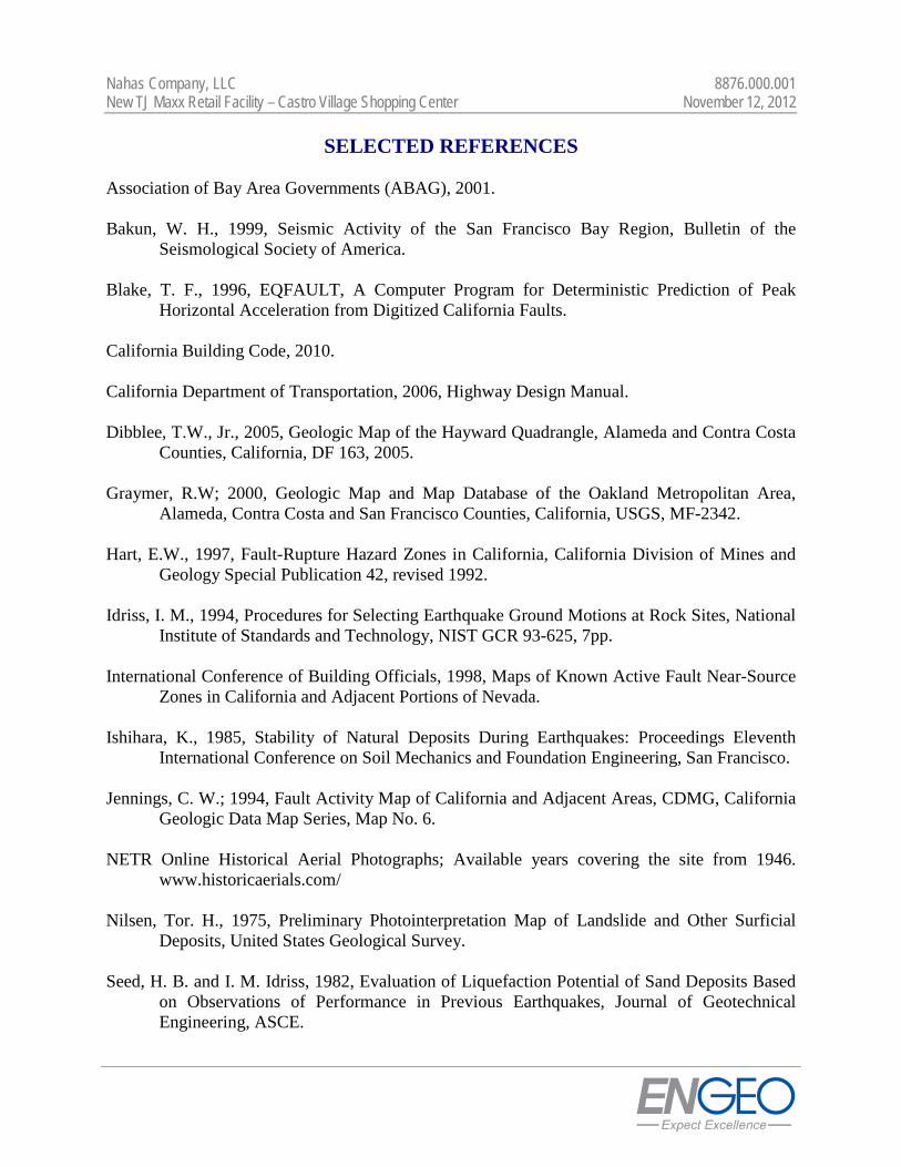
See exploration logs.#200 60.2
The Nahas CompanyNew TJ Maxx Building
8876.000.001
Soil Description
Atterberg Limits
Coefficients
Classification
Remarks
Sample Number: 1-B4 @ 11 Depth: 11 feetDate:
Client:Project:
Project No:
SIEVE PERCENT SPEC.* PASS?
SIZE FINER PERCENT (X=NO)
PE
RC
EN
TFI
NER
0
10
20
30
40
50
60
70
80
90
100
GRAIN SIZE - mm.
0.0010.010.1110100
% +3"Coarse
% GravelFine Coarse Medium
% SandFine Silt
% FinesClay
60.2
6in
.
3in
.
2in
.1½
in.
1in
.¾
in.
½in
.
3/8
in.
#4 #10
#20
#30
#40
#60
#100
#140
#200
Particle Size Distribution Report
Tested By: AV Checked By: DS
11.6.12
(no specification provided)
PL= LL= PI=
D90= D85= D60=D50= D30= D15=D10= Cu= Cc=
USCS= AASHTO=
*
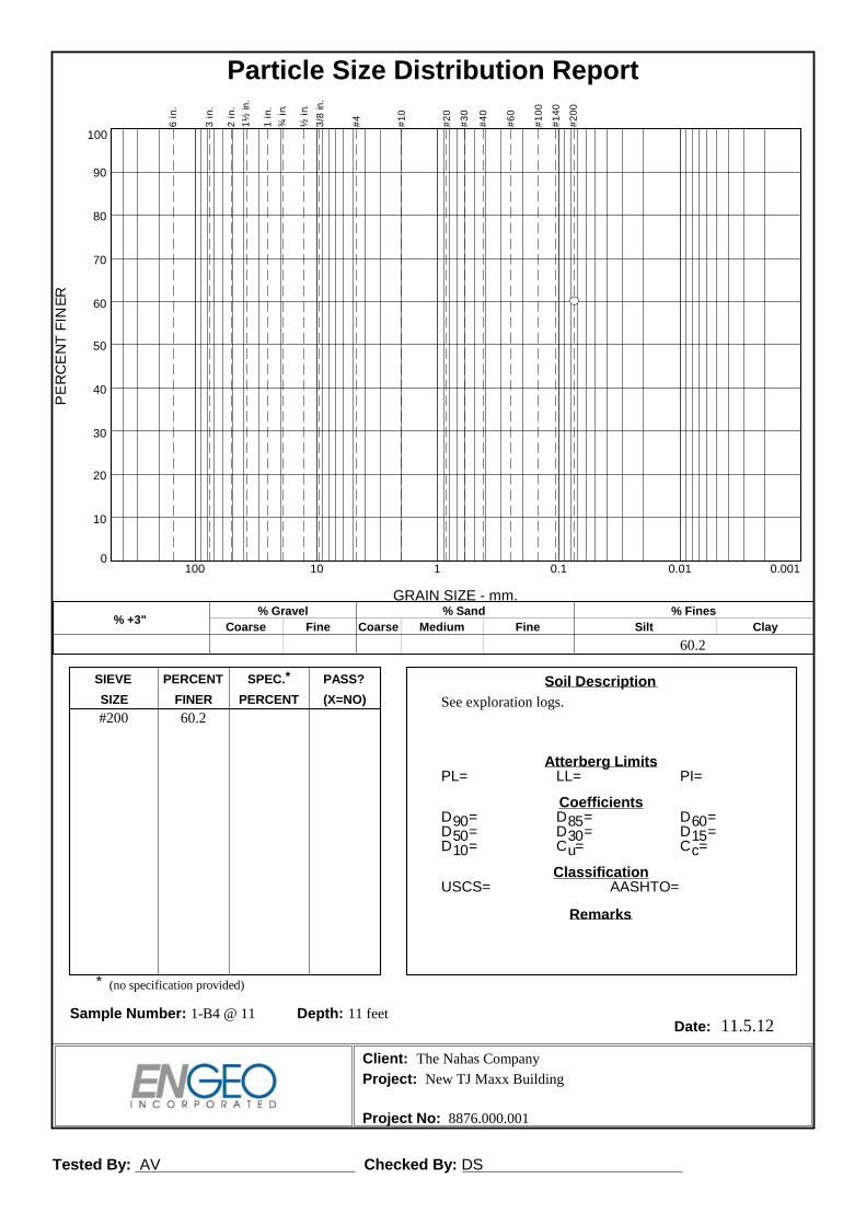
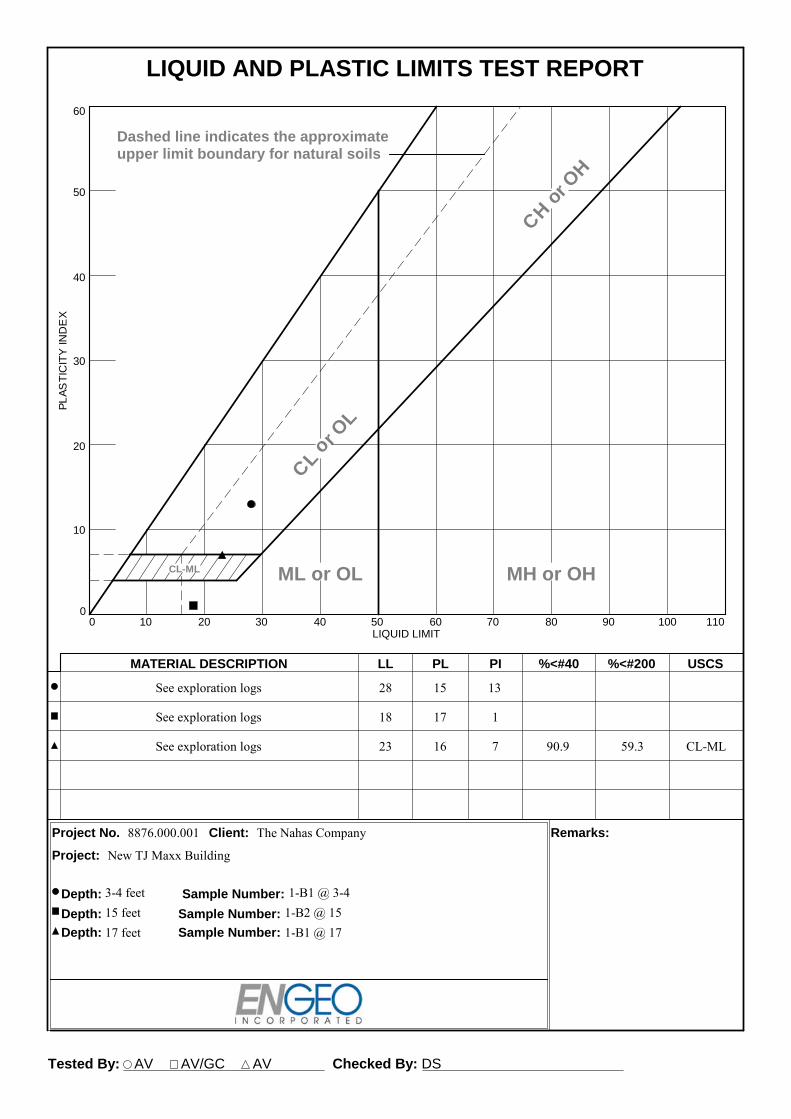
See exploration logs3/8#4#10#20#40#60#100#140#200
0.0309 mm.0.0202 mm.0.0173 mm.0.0120 mm.0.0086 mm.0.0061 mm.0.0043 mm.0.0035 mm.0.0030 mm.0.0021 mm.0.0013 mm.
100.098.695.593.590.984.474.966.759.338.130.828.624.922.019.017.616.114.613.913.2
16 23 7
0.3852 0.2601 0.07750.0511 0.0192 0.0031
CL-ML A-4(1)
The Nahas CompanyNew TJ Maxx Building
8876.000.001
Soil Description
Atterberg Limits
Coefficients
Classification
Remarks
Sample Number: 1-B1 @ 17 Depth: 17 feetDate:
Client:Project:
Project No:
SIEVE PERCENT SPEC.* PASS?
SIZE FINER PERCENT (X=NO)
PE
RC
EN
TFI
NER
0
10
20
30
40
50
60
70
80
90
100
GRAIN SIZE - mm.
0.0010.010.1110100
% +3"Coarse
% GravelFine Coarse Medium
% SandFine Silt
% FinesClay
0.0 0.0 1.4 3.1 4.6 31.6 41.1 18.2
6in
.
3in
.
2in
.1½
in.
1in
.¾
in.
½in
.
3/8
in.
#4 #10
#20
#30
#40
#60
#100
#140
#200
Particle Size Distribution Report

1-B1 1-B1 1-B2 1-B3 1-B4
6 31 26 16 11
SF PVM D H T
3.54 5.15 5.53 5.00 3.59
2.410 2.400 2.400 2.420 2.410
0.8351 0.8421 0.8421 0.8282 0.8351
628.8 888.6 982.2 890.4 621.3
545.1 748.4 849.5 763.4 537.0
85.1 85.2 87.0 81.5 85.8
83.7 140.2 132.7 127.0 84.3
460.0 663.2 762.6 681.9 451.2
18.2 21.1 17.4 18.6 18.7108.5 108.4 116.1 112.9 105.0
PROJECT NAME: DATE: 11/02/12PROJECT NUMBER:
CLIENT:PHASE NUMBER: GEX
Tested by: AV
New TJ Maxx Geotechnical Exploration8876.000.001The Nahas Company
WT. OF DRY SOIL, (GM.)
ASTM D7263
DRY WT. + TARE (GM.)
TARE WT. (GM)
WT. OF WATER (GM.)
WATER CONTENT (%)DRY DENSITY (PCF)
TARE NAME
SAMPLE HEIGHT (IN.)
DENSITY FACTOR
WET WT. + TARE (GM.)
DIAMETER (IN.)
MOISTURE-DENSITY DETERMINATION
DEPTH (FT.)
SAMPLE NO.
Engeo Incorporated, 2057 San Ramon Valley Blvd., San Ramon, CA 94583 (925) 837-2973
Tested By: AV AV/GC AV Checked By: DS
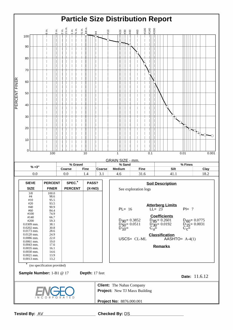
See exploration logs 28 15 13
See exploration logs 18 17 1
See exploration logs 23 16 7 90.9 59.3 CL-ML
8876.000.001 The Nahas Company
MATERIAL DESCRIPTION LL PL PI %<#40 %<#200 USCS
Project No. Client: Remarks:
Project:
Depth: 3-4 feet Sample Number: 1-B1 @ 3-4
Depth: 15 feet Sample Number: 1-B2 @ 15Depth: 17 feet Sample Number: 1-B1 @ 17
PL
AS
TIC
ITY
IND
EX
0
10
20
30
40
50
60
LIQUID LIMIT0 10 20 30 40 50 60 70 80 90 100 110
CL-ML
CLor OL
CHor OH
ML or OL MH or OH
Dashed line indicates the approximateupper limit boundary for natural soils
47
LIQUID AND PLASTIC LIMITS TEST REPORT
New TJ Maxx Building

Unconfined Compression Test - Results Page 1 of 1 Test File Name
Client [email protected]
Dat
e11
.8.1
2
Sample ID
1-B4@6Unconfined Compressive
Strength (psi)
2.068
2.07
0.050000
Project Information
Unconfined Compressive Strength (tsf)
5.000
Test
ed B
yD
. Sei
bold
44.52
1-B4@6
104.100
G. C
riste
Com
pute
d B
y
Water Content (%) 9.89Dry Density (pcf)Saturation (%)
Diameter (in)Height (in)Test Data
New TJ Maxx Retail Facility
The Nahas CompanyLocation
28.748
14.374
Height-to-Diameter Ratio
Rate of Strain (in/min)
Remarks
Undrained Shear Strength (psi)
Description
Plastic Limit:Liquid Limit:
See exploration logs
Test Date
8876.000.001
Index PropertiesSpecific Gravity:
1-B4@6
Project Name
Dat
eD
ate
0.59 2.420
11.8
.12
Before Test
Void Ratio
EN GEO Unconfined Compression Test Report (ASTM D2166)
1-B4@6
Che
cked
By
Project Number
Specimen
Strain at Failure (%) 2.23
0.000
5.000
10.000
15.000
20.000
25.000
30.000
35.000
0.000 0.500 1.000 1.500 2.000 2.500 3.000 3.500
Cor
rect
ed C
ompr
essi
ve S
tres
s (ps
i)
Axial Strain (%)
Compressive Stress Axial Strain Curve
1-B4@6

mg/kg1 soil 2
Date: 11.8.12
GEX
AVDS
Tested by:Reviewed by:
SULFATE CONTENT IN SOILSCALTRANS TEST METHOD 417
MatrixSample IDSample Number
1-B1 @ 2'
The Nahas Company8876.000.001
Client:Project Name:
Project Number:
Water soluble sulfate in soil
Phase Number:
New TJ Maxx Building
% by weight0.000
Laboratory Address: 2057 San Ramon Valley Blvd San Ramon, CA 94583 (925)837-2973

APPENDIX C
Guide Contract Specifications
APPENDIX
C

Nahas Company, LLC 8876.000.001 New TJ Maxx Retail Facility – Castro Village Shopping Center November 12, 2012
C - 1
GUIDE CONTRACT SPECIFICATIONS PART I - EARTHWORK PREFACE These specifications are intended as a guide for the earthwork performed at the subject development project. If there is a conflict between these specifications (including the recommendations of the geotechnical report) and agency or code requirements, it should be brought to the attention of ENGEO and Owner prior to contract bidding. PART 1 - GENERAL 1.01 WORK COVERED A. Grading, excavating, filling and backfilling, including trenching and backfilling for
utilities as necessary to complete the Project as indicated on the Drawings. B. Subsurface drainage as indicated on the Drawings. 1.02 CODES AND STANDARDS A. Excavating, trenching, filling, backfilling, and grading work shall meet the applicable
requirements of the Uniform Building Code and the standards and ordinances of state and local governing authorities.
1.03 SUBSURFACE SOIL CONDITIONS A. The Owners' Geotechnical Exploration report is available for inspection by bidder or
Contractor. The Contractor shall refer to the findings and recommendations of the Geotechnical Exploration report in planning and executing his work.
1.04 DEFINITIONS A. Fill: All soil, rock, or soil-rock materials placed to raise the grades of the site or to
backfill excavations. B. Backfill: All soil, rock or soil-rock material used to fill excavations and trenches. C. Onsite Material: Soil and/or rock material, which is obtained from the site. D. Imported Material: Soil and/or rock material, which is brought to the site from offsite
areas.

Nahas Company, LLC 8876.000.001 New TJ Maxx Retail Facility – Castro Village Shopping Center November 12, 2012
C - 2
E. Select Material: Onsite and/or imported material, which is approved by ENGEO as a
specific-purpose fill. F. Engineered Fill: Fill upon which ENGEO has made sufficient observations and tests to
confirm that the fill has been placed and compacted in accordance with specifications and requirements.
G. Degree of Compaction or Relative Compaction: The ratio, expressed as a percentage,
of the in-place dry density of the fill and backfill material as compacted in the field to the maximum dry density of the same material as determined by ASTM D-1557 or California 216 compaction test method.
H. Optimum Moisture: Water content, percentage by dry weight, corresponding to the
maximum dry density as determined by ASTM D-1557. I. ENGEO: The project geotechnical engineering consulting firm, its employees or its
designated representatives. J. Drawings: All documents, approved for construction, which describe the Work. 1.05 OBSERVATION AND TESTING A. All site preparation, cutting and shaping, excavating, filling, and backfilling shall be
carried out under the observation of ENGEO, employed and paid for by the Owners. ENGEO will perform appropriate field and laboratory tests to evaluate the suitability of fill material, the proper moisture content for compaction, and the degree of compaction achieved. Any fill that does not meet the specification requirements shall be removed and/or reworked until the requirements are satisfied.
B. Cutting and shaping, excavating, conditioning, filling, and compacting procedures
require approval of ENGEO as they are performed. Any work found unsatisfactory or any work disturbed by subsequent operations before approval is granted shall be corrected in an approved manner as recommended by ENGEO.
C. Tests for compaction will be made in accordance with test procedures outlined in
ASTM D-1557, as applicable. Field testing of soils or compacted fill shall conform with the applicable requirements of ASTM D-2922.
D. All authorized observation and testing will be paid for by the Owners.

Nahas Company, LLC 8876.000.001 New TJ Maxx Retail Facility – Castro Village Shopping Center November 12, 2012
C - 3
1.06 SITE CONDITIONS A. Excavating, filling, backfilling, and grading work shall not be performed during
unfavorable weather conditions. When the work is interrupted by rain, excavating, filling, backfilling, and grading work shall not be resumed until the site and soil conditions are suitable.
B. Contractor shall take the necessary measures to prevent erosion of freshly filled,
backfilled, and graded areas until such time as permanent drainage and erosion control measures have been installed.
PART 2 - PRODUCTS 2.01 GENERAL A. Contractor shall furnish all materials, tools, equipment, facilities, and services as
required for performing the required excavating, filling, backfilling, and grading work, and trenching and backfilling for utilities.
2.02 SOIL MATERIALS A. Fill 1. Material to be used for engineered fill and backfill shall be free from organic
matter and other deleterious substances, and of such quality that it will compact thoroughly without excessive voids when watered and rolled. Excavated onsite material will be considered suitable for engineered fill and backfill if it contains no more than 3 percent organic matter, is free of debris and other deleterious substances and conforms to the requirements specified above. Rocks of maximum dimension in excess of two-thirds of the lift thickness shall be removed from any fill material to the satisfaction of ENGEO.
2. Excavated earth material, which is suitable for engineered fill or backfill, as
determined by ENGEO, shall be conditioned for reuse and properly stockpiled as required for later filling and backfilling operations. Conditioning shall consist of spreading material in layers not to exceed 8 inches and raking free of debris and rubble. Rocks and aggregate exceeding the allowed largest dimension, and deleterious material shall be removed from the site and disposed offsite in a legal manner.
3. ENGEO shall be immediately notified if potential hazardous materials or suspect
soils exhibiting staining or odor are encountered. Work activities shall be discontinued within the area of potentially hazardous materials. ENGEO environmental personnel will conduct an assessment of the suspect hazardous material to determine the appropriate response and mitigation. Regulatory

Nahas Company, LLC 8876.000.001 New TJ Maxx Retail Facility – Castro Village Shopping Center November 12, 2012
C - 4
agencies may also be contacted to request concurrence and oversight. ENGEO will rely on the Owner, or a designated Owner’s representative, to make necessary notices to the appropriate regulatory agencies. The Owner may request ENGEO’s assistance in notifying regulatory agencies, provided ENGEO receives Owner’s written authorization to expand its scope of services.
4. ENGEO shall be notified at least 48 hours prior to the start of filling and
backfilling operations so that it may evaluate samples of the material intended for use as fill and backfill. All materials to be used for filling and backfilling require the approval of ENGEO.
B. Import/Select Material: Where conditions require the importation of fill material, the
material shall be an inert, nonexpansive soil or soil-rock material free of organic matter and meeting the following requirements unless otherwise approved by ENGEO.
Gradation (ASTM D-421): Sieve Size Percent Passing 2-inch 100 #200 15 - 70 Plasticity (ASTM D-4318): Liquid Limit Plasticity Index < 30 < 12 Swell Potential (ASTM D-4546B): Percent Heave Swell Pressure (at optimum moisture) < 2 percent < 300 psf Resistance Value (ASTM D-2844): Minimum 25 Organic Content (ASTM D-2974): Less than 2 percent A sample of the proposed import material should be submitted to ENGEO for
evaluation prior to delivery at the site. 2.03 SAND A. Sand for sand cushion under slabs and for bedding of pipe in utility trenches shall be a
clean and graded, washed sand, free from clay or organic material, suitable for the intended purpose with 90 to 100 percent passing a No. 4 U.S. Standard Sieve, not more than 5 percent passing a No. 200 U.S. Standard Sieve, and generally conforming to ASTM C33 for fine aggregate.
2.04 AGGREGATE DRAINAGE FILL A. Aggregate drainage fill under concrete slabs and paving shall consist of broken stone,
crushed or uncrushed gravel, clean quarry waste, or a combination thereof. The aggregate shall be free from fines, vegetable matter, loam, volcanic tuff, and other

Nahas Company, LLC 8876.000.001 New TJ Maxx Retail Facility – Castro Village Shopping Center November 12, 2012
C - 5
deleterious substances. It shall be of such quality that the absorption of water in a saturated surface dry condition does not exceed 3 percent of the oven dry weight of the samples.
B. Aggregate drainage fill shall be of such size that the percentage composition by dry
weight as determined by laboratory sieves (U. S. Series) will conform to the following grading:
Sieve Size Percentage Passing Sieve 1½-inches 100 1-inch 90 - 100 #4 0 - 5 2.05 SUBDRAINS A. Perforated subdrain pipe of the required diameter shall be installed as shown on the
drawings. The pipe(s) shall also conform to these specifications unless otherwise specified by ENGEO in the field.
Subdrain pipe shall be manufactured in accordance with one of the following
requirements: Design depths less than 30 feet - Perforated ABS Solid Wall SDR 35 (ASTM D-2751) - Perforated PVC Solid Wall SDR 35 (ASTM D-3034) - Perforated PVC A-2000 (ASTM F949) - Perforated Corrugated HDPE double-wall (AASHTO M-252 or M-294,
Caltrans Type S, 50 psi minimum stiffness) Design depths less than 50 feet - Perforated PVC SDR 23.5 Solid Wall (ASTM D-3034) - Perforated Sch. 40 PVC Solid Wall (ASTM-1785) - Perforated ABS SDR 23.5 Solid Wall (ASTM D-2751) - Perforated ABS DWV/Sch. 40 (ASTM D-2661 and D-1527) - Perforated Corrugated HDPE double-wall (AASHTO M-252 or M-294,
Caltrans Type S, 70 psi minimum stiffness) Design depths less than 70 feet - Perforated ABS Solid Wall SDR 15.3 (ASTM D-2751) - Perforated Sch. 80 PVC (ASTM D-1785) - Perforated Corrugated Aluminum (ASTM B-745) B. Permeable Material (Class 2): Class 2 permeable material for filling trenches under,
around, and over subdrains, behind building and retaining walls, and for pervious
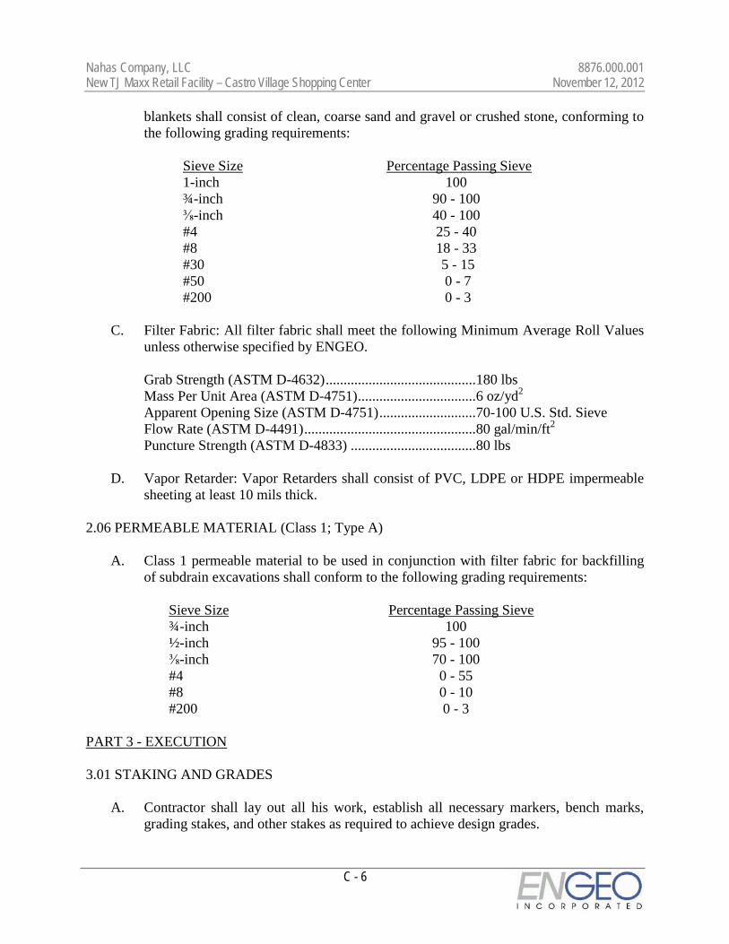
Nahas Company, LLC 8876.000.001 New TJ Maxx Retail Facility – Castro Village Shopping Center November 12, 2012
C - 6
blankets shall consist of clean, coarse sand and gravel or crushed stone, conforming to the following grading requirements:
Sieve Size Percentage Passing Sieve 1-inch 100 ¾-inch 90 - 100 ⅜-inch 40 - 100 #4 25 - 40 #8 18 - 33 #30 5 - 15 #50 0 - 7 #200 0 - 3 C. Filter Fabric: All filter fabric shall meet the following Minimum Average Roll Values
unless otherwise specified by ENGEO. Grab Strength (ASTM D-4632) .......................................... 180 lbs Mass Per Unit Area (ASTM D-4751) ................................. 6 oz/yd2 Apparent Opening Size (ASTM D-4751) ........................... 70-100 U.S. Std. Sieve Flow Rate (ASTM D-4491) ................................................ 80 gal/min/ft2 Puncture Strength (ASTM D-4833) ................................... 80 lbs D. Vapor Retarder: Vapor Retarders shall consist of PVC, LDPE or HDPE impermeable
sheeting at least 10 mils thick. 2.06 PERMEABLE MATERIAL (Class 1; Type A) A. Class 1 permeable material to be used in conjunction with filter fabric for backfilling
of subdrain excavations shall conform to the following grading requirements: Sieve Size Percentage Passing Sieve ¾-inch 100 ½-inch 95 - 100 ⅜-inch 70 - 100 #4 0 - 55 #8 0 - 10 #200 0 - 3 PART 3 - EXECUTION 3.01 STAKING AND GRADES A. Contractor shall lay out all his work, establish all necessary markers, bench marks,
grading stakes, and other stakes as required to achieve design grades.

Nahas Company, LLC 8876.000.001 New TJ Maxx Retail Facility – Castro Village Shopping Center November 12, 2012
C - 7
3.02 EXISTING UTILITIES A. Contractor shall verify the location and depth (elevation) of all existing utilities and
services before performing any excavation work. 3.03 EXCAVATION A. Contractor shall perform excavating as indicated and required for concrete footings,
drilled piers, foundations, floor slabs, concrete walks, and site leveling and grading, and provide shoring, bracing, underpinning, cribbing, pumping, and planking as required. The bottoms of excavations shall be firm undisturbed earth, clean and free from loose material, debris, and foreign matter.
B. Excavations shall be kept free from water at all times. Adequate dewatering equipment
shall be maintained at the site to handle emergency situations until concrete or backfill is placed.
C. Unauthorized excavations for footings shall be filled with concrete to required
elevations, unless other methods of filling are authorized by ENGEO. D. Excavated earth material, which is suitable for engineered fill or backfill, as
determined by ENGEO, shall be conditioned for reuse and properly stockpiled for later filling and backfilling operations as specified under Section 2.02, "Soil Materials."
E. Abandoned sewers, piping, and other utilities encountered during excavating shall be
removed and the resulting excavations shall be backfilled with engineered fill as required by ENGEO.
F. Any active utility lines encountered shall be reported immediately to the Owner's
Representative and authorities involved. The Owner and proper authorities shall be permitted free access to take the measures deemed necessary to repair, relocate, or remove the obstruction as determined by the responsible authority or Owner's Representative.
3.04 SUBGRADE PREPARATION A. All brush and other rubbish, as well as trees and root systems not marked for saving,
shall be removed from the site and legally disposed of. B. Any existing structures, foundations, underground storage tanks, or debris must be
removed from the site prior to any building, grading, or fill operations. Septic tanks, including all drain fields and other lines, if encountered, must be totally removed. The resulting depressions shall be properly prepared and filled to the satisfaction of ENGEO.

Nahas Company, LLC 8876.000.001 New TJ Maxx Retail Facility – Castro Village Shopping Center November 12, 2012
C - 8
C. Vegetation and organic topsoil shall be removed from the surface upon which the fill is to be placed and either removed and legally disposed of or stockpiled for later use in approved landscape areas. The surface shall then be scarified to a depth of at least eight inches until the surface is free from ruts, hummocks, or other uneven features which would tend to prevent uniform compaction by the equipment to be used.
D. After the foundation for the fill has been cleared and scarified, it shall be made
uniform and free from large clods. The proper moisture content must be obtained by adding water or aerating. The foundation for the fill shall be compacted at the proper moisture content to a relative compaction as specified herein.
3.05 ENGINEERED FILL A. Select Material: Fill material shall be "Select" or "Imported Material" as previously
specified. B. Placing and Compacting: Engineered fill shall be constructed by approved and
accepted methods. Fill material shall be spread in uniform lifts not exceeding 8 inches in uncompacted thickness. Each layer shall be spread evenly, and thoroughly blade-mixed to obtain uniformity of material. Fill material, which does not contain sufficient moisture as specified by ENGEO, shall be sprinkled with water; if it contains excess moisture it shall be aerated or blended with drier material to achieve the proper water content. Select material and water shall then be thoroughly mixed before being compacted.
C. Unless otherwise specified in the Geotechnical Exploration report, each layer of spread
select material shall be compacted to at least 90 percent relative compaction at a moisture content of at least three percentage points above the optimum moisture content. Minimum compaction in all keyways shall be a minimum of 95 percent with a minimum moisture content of at least 1 percentage point above optimum.
D. Unless otherwise specified in the Geotechnical Exploration report or otherwise
required by the local authorities, the upper 6 inches of engineered fill in areas to receive pavement shall be compacted to at least 95 percent relative compaction with a minimum moisture content of at least 3 percentage points above optimum.
E. Testing and Observation of Fill: The work shall consist of field observation and testing
to determine that each layer has been compacted to the required density and that the required moisture is being obtained. Any layer or portion of a layer that does not attain the compaction required shall be reworked until the required density is obtained.
F. Compaction: Compaction shall be by sheepsfoot rollers, multiple-wheel steel or
pneumatic-tired rollers or other types of acceptable compaction equipment. Rollers shall be of such design that they will be able to compact the fill to the specified

Nahas Company, LLC 8876.000.001 New TJ Maxx Retail Facility – Castro Village Shopping Center November 12, 2012
C - 9
compaction. Rolling shall be accomplished while the fill material is within the specified moisture content range. Rolling of each layer must be continuous so that the required compaction may be obtained uniformly throughout each layer.
G. Fill slopes shall be constructed by overfilling the design slopes and later cutting back
the slopes to the design grades. No loose soil will be permitted on the faces of the finished slopes.
H. Strippings and topsoil shall be stockpiled as approved by Owner, then placed in
accordance with ENGEO's recommendations to a minimum thickness of 6 inches and a maximum thickness of 12 inches over exposed open space cut slopes which are 3:1 or flatter, and track walked to the satisfaction of ENGEO.
I. Final Prepared Subgrade: Finish blading and smoothing shall be performed as
necessary to produce the required density, with a uniform surface, smooth and true to grade.
3.06 BACKFILLING A. Backfill shall not be placed against footings, building walls, or other structures until
approved by ENGEO. B. Backfill material shall be Select Material as specified for engineered fill. C. Backfill shall be placed in 6-inch layers, leveled, rammed, and tamped in place. Each
layer shall be compacted with suitable compaction equipment to 90 percent relative compaction at a moisture content of at least 3 percent above optimum.
3.07 TRENCHING AND BACKFILLING FOR UTILITIES A. Trenching: 1. Trenching shall include the removal of material and obstructions, the installation
and removal of sheeting and bracing and the control of water as necessary to provide the required utilities and services.
2. Trenches shall be excavated to the lines, grades, and dimensions indicated on the
Drawings. Maximum allowable trench width shall be the outside diameter of the pipe plus 24 inches, inclusive of any trench bracing.
3. When the trench bottom is a soft or unstable material as determined by ENGEO, it
shall be made firm and solid by removing said unstable material to a sufficient depth and replacing it with onsite material compacted to 90 percent minimum relative compaction.

Nahas Company, LLC 8876.000.001 New TJ Maxx Retail Facility – Castro Village Shopping Center November 12, 2012
C - 10
4. Where water is encountered in the trench, the contractor must provide materials necessary to drain the water and stabilize the bed.
B. Backfilling: 1. Trenches must be backfilled within 2 days of excavation to minimize desiccation. 2. Bedding material shall be sand and shall not extend more than 6 inches above any
utility lines. 3. Backfill material shall be select material. 4. Trenches shall be backfilled as indicated or required and compacted with suitable
equipment to 90 percent minimum relative compaction at the required moisture content.
3.08 SUBDRAINS A. Trenches for subdrain pipe shall be excavated to a minimum width equal to the outside
diameter of the pipe plus at least 12 inches and to a depth of approximately 2 inches below the grade established for the invert of the pipe, or as indicated on the Drawings.
B. The space below the pipe invert shall be filled with a layer of Class 2 permeable
material, upon which the pipe shall be laid with perforations down. Sections shall be joined as recommended by the pipe manufacturer.
C. Rocks, bricks, broken concrete, or other hard material shall not be used to give
intermediate support to pipes. Large stones or other hard objects shall not be left in contact with the pipes.
D. Excavations for subdrains shall be filled as required to fill voids and prevent settlement
without damaging the subdrain pipe. Alternatively, excavations for subdrains may be filled with Class 1 permeable material (as defined in Section 2.06) wrapped in Filter Fabric (as defined in Section 2.05).
3.09 AGGREGATE DRAINAGE FILL A. ENGEO shall approve finished subgrades before aggregate drainage fill is installed. B. Pipes, drains, conduits, and any other mechanical or electrical installations shall be in
place before any aggregate drainage fill is placed. Backfill at walls to elevation of drainage fill shall be in place and compacted.

Nahas Company, LLC 8876.000.001 New TJ Maxx Retail Facility – Castro Village Shopping Center November 12, 2012
C - 11
C. Aggregate drainage fill under slabs and concrete paving shall be the minimum uniform thickness after compaction of dimensions indicated on Drawings. Where not indicated, minimum thickness after compaction shall be 4 inches.
D. Aggregate drainage fill shall be rolled to form a well-compacted bed. E. The finished aggregate drainage fill must be observed and approved by ENGEO before
proceeding with any subsequent construction over the compacted base or fill. 3.10 SAND CUSHION A. A sand cushion may be placed over the vapor retarder membrane under concrete slabs
on grade. Sand cushion may be placed in uniform thickness as indicated on the Drawings. Where not indicated, the thickness shall be 2 inches.
3.11 FINISH GRADING A. All areas must be finish graded to elevations and grades indicated on the Drawings. In
areas to receive topsoil and landscape planting, finish grading shall be performed to a uniform 6 inches below the grades and elevations indicated on the Drawings, and brought to final grade with topsoil.
3.12 DISPOSAL OF WASTE MATERIALS A. Excess earth materials and debris shall be removed from the site and disposed of in a
legal manner. Location of dump site and length of haul are the Contractor's responsibility.

Nahas Company, LLC 8876.000.001 New TJ Maxx Retail Facility – Castro Village Shopping Center November 12, 2012
C - 12
PART II - GEOGRID SOIL REINFORCEMENT 1. DESCRIPTION: Work shall consist of furnishing geogrid soil reinforcement for use in construction of
reinforced soil slopes and retention systems. 2. GEOGRID MATERIAL: 2.1 The specific geogrid material shall be preapproved by ENGEO. 2.2 The geogrid shall be a regular network of integrally connected polymer tensile elements
with aperture geometry sufficient to permit significant mechanical interlock with the surrounding soil or rock. The geogrid structure shall be dimensionally stable and able to retain its geometry under construction stresses and shall have high resistance to damage during construction, to ultraviolet degradation, and to all forms of chemical and biological degradation encountered in the soil being reinforced.
2.3 The geogrids shall have an Allowable Strength (Ta) and Pullout Resistance, for the soil
type(s) indicated, as listed in Table I. 2.4 Certifications: The Contractor shall submit a manufacturer's certification that the
geogrids supplied meet the respective index criteria set when geogrid was approved by ENGEO, measured in full accordance with all test methods and standards specified. In case of dispute over validity of values, the Contractor will supply test data from an ENGEO-approved laboratory to support the certified values submitted.
3. CONSTRUCTION: 3.1 Delivery, Storage, and Handling: Contractor shall check the geogrid upon delivery to
ensure that the proper material has been received. During all periods of shipment and storage, the geogrid shall be protected from temperatures greater than 140 °F, mud, dirt, dust, and debris. Manufacturer's recommendations in regard to protection from direct sunlight must also be followed. At the time of installation, the geogrid will be rejected if it has defects, tears, punctures, flaws, deterioration, or damage incurred during manufacture, transportation, or storage. If approved by ENGEO, torn or punctured sections may be repaired by placing a patch over the damaged area. Any geogrid damaged during storage or installation shall be replaced by the Contractor at no additional cost to the owner.
3.2 Onsite Representative: Geogrid material suppliers shall provide a qualified and
experienced representative onsite at the initiation of the project, for a minimum of three days, to assist the Contractor and ENGEO personnel at the start of construction. If there is more than one slope on a project, this criterion will apply to construction of the initial

Nahas Company, LLC 8876.000.001 New TJ Maxx Retail Facility – Castro Village Shopping Center November 12, 2012
C - 13
slope only. The representative shall also be available on an as-needed basis, as requested by ENGEO, during construction of the remaining slope(s).
3.3 Geogrid reinforcement may be joined with mechanical connections or overlaps as
recommended and approved by the Manufacturer. Joints shall not be placed within 6 feet of the slope face, within 4 feet below top of slope, nor horizontally or vertically adjacent to another joint.
3.4 Geogrid Placement: The geogrid reinforcement shall be installed in accordance with the
manufacturer's recommendations. The geogrid reinforcement shall be placed within the layers of the compacted soil as shown on the plans or as directed.
The geogrid reinforcement shall be placed in continuous longitudinal strips in the
direction of main reinforcement. However, if the Contractor is unable to complete a required length with a single continuous length of geogrid, a joint may be made with the Manufacturer's approval. Only one joint per length of geogrid shall be allowed. This joint shall be made for the full width of the strip by using a similar material with similar strength. Joints in geogrid reinforcement shall be pulled and held taut during fill placement.
Adjacent strips, in the case of 100 percent coverage in plan view, need not be overlapped.
The minimum horizontal coverage is 50 percent, with horizontal spacings between reinforcement no greater than 40 inches. Horizontal coverage of less than 100 percent shall not be allowed unless specifically detailed in the construction drawings.
Adjacent rolls of geogrid reinforcement shall be overlapped or mechanically connected
where exposed in a wrap around face system, as applicable. The Contractor may place only that amount of geogrid reinforcement required for
immediately pending work to prevent undue damage. After a layer of geogrid reinforcement has been placed, the next succeeding layer of soil shall be placed and compacted as appropriate. After the specified soil layer has been placed, the next geogrid reinforcement layer shall be installed. The process shall be repeated for each subsequent layer of geogrid reinforcement and soil.
Geogrid reinforcement shall be placed to lay flat and pulled tight prior to backfilling.
After a layer of geogrid reinforcement has been placed, suitable means, such as pins or small piles of soil, shall be used to hold the geogrid reinforcement in position until the subsequent soil layer can be placed.
Under no circumstances shall a track-type vehicle be allowed on the geogrid
reinforcement before at least six inches of soil have been placed. Turning of tracked vehicles should be kept to a minimum to prevent tracks from displacing the fill and the geogrid reinforcement. If approved by the Manufacturer, rubber-tired equipment may
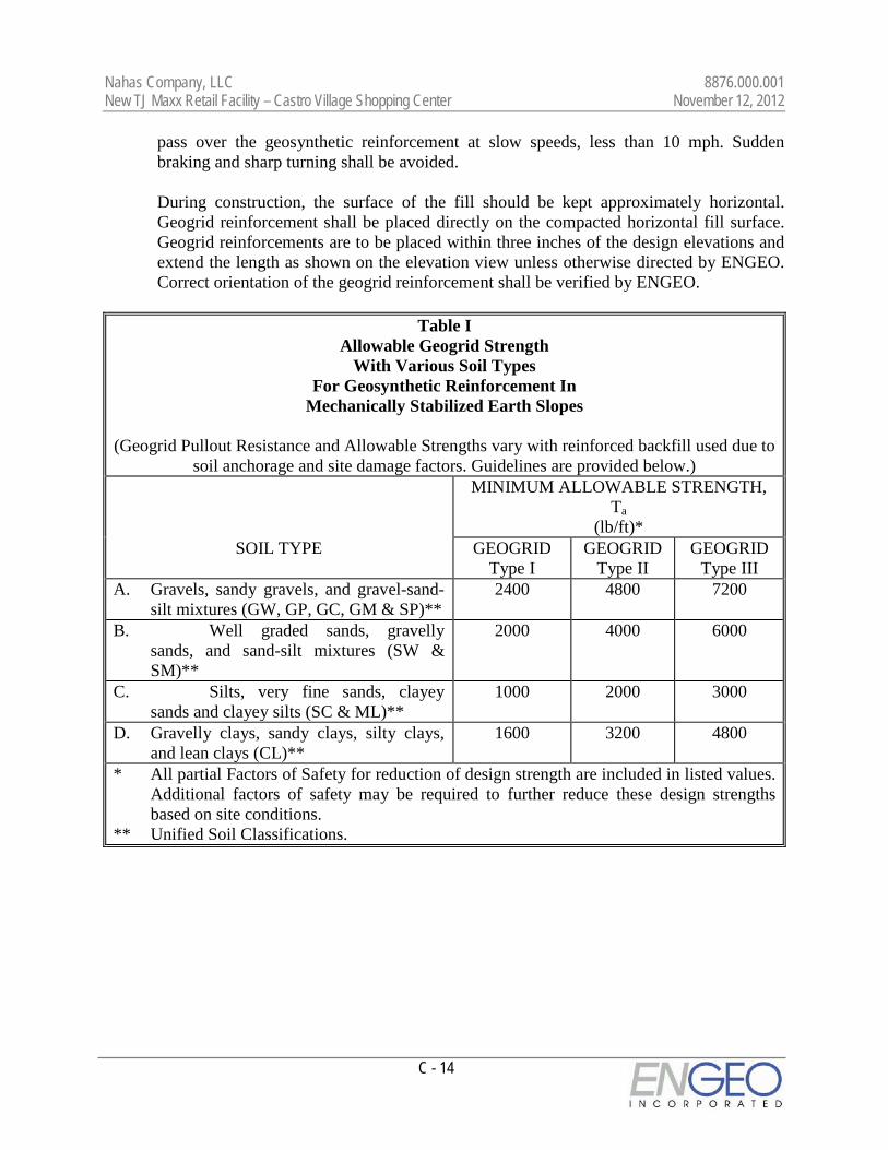
Nahas Company, LLC 8876.000.001 New TJ Maxx Retail Facility – Castro Village Shopping Center November 12, 2012
C - 14
pass over the geosynthetic reinforcement at slow speeds, less than 10 mph. Sudden braking and sharp turning shall be avoided.
During construction, the surface of the fill should be kept approximately horizontal.
Geogrid reinforcement shall be placed directly on the compacted horizontal fill surface. Geogrid reinforcements are to be placed within three inches of the design elevations and extend the length as shown on the elevation view unless otherwise directed by ENGEO. Correct orientation of the geogrid reinforcement shall be verified by ENGEO.
Table I
Allowable Geogrid Strength With Various Soil Types
For Geosynthetic Reinforcement In Mechanically Stabilized Earth Slopes
(Geogrid Pullout Resistance and Allowable Strengths vary with reinforced backfill used due to
soil anchorage and site damage factors. Guidelines are provided below.) MINIMUM ALLOWABLE STRENGTH,
Ta (lb/ft)*
SOIL TYPE GEOGRID Type I
GEOGRID Type II
GEOGRID Type III
A. Gravels, sandy gravels, and gravel-sand-silt mixtures (GW, GP, GC, GM & SP)**
2400 4800 7200
B. Well graded sands, gravelly sands, and sand-silt mixtures (SW & SM)**
2000 4000 6000
C. Silts, very fine sands, clayey sands and clayey silts (SC & ML)**
1000 2000 3000
D. Gravelly clays, sandy clays, silty clays, and lean clays (CL)**
1600 3200 4800
* All partial Factors of Safety for reduction of design strength are included in listed values. Additional factors of safety may be required to further reduce these design strengths based on site conditions.
** Unified Soil Classifications.
Nahas Company, LLC 8876.000.001 New TJ Maxx Retail Facility – Castro Village Shopping Center November 12, 2012
C - 15
PART III - GEOTEXTILE SOIL REINFORCEMENT 1. DESCRIPTION: Work shall consist of furnishing geotextile soil reinforcement for use in construction of
reinforced soil slopes. 2. GEOTEXTILE MATERIAL: 2.1 The specific geotextile material and supplier shall be preapproved by ENGEO. 2.2 The geotextile shall have a high tensile modulus and shall have high resistance to damage
during construction, to ultraviolet degradation, and to all forms of chemical and biological degradation encountered in the soil being reinforced.
2.3 The geotextiles shall have an Allowable Strength (Ta) and Pullout Resistance, for the soil
type(s) indicated as listed in Table II. 2.4 Certification: The Contractor shall submit a manufacturer's certification that the
geotextiles supplied meet the respective index criteria set when geotextile was approved by ENGEO, measured in full accordance with all test methods and standards specified. In case of dispute over validity of values, the Contractor will supply the data from an ENGEO-approved laboratory to support the certified values submitted.
3. CONSTRUCTION: 3.1 Delivery, Storage and Handling: Contractor shall check the geotextile upon delivery to
ensure that the proper material has been received. During all periods of shipment and storage, the geotextile shall be protected from temperatures greater than 140 °F, mud, dirt, dust, and debris. Manufacturer's recommendations in regard to protection from direct sunlight must also be followed. At the time of installation, the geotextile will be rejected if it has defects, tears, punctures, flaws, deterioration, or damage incurred during manufacture, transportation, or storage. If approved by ENGEO, torn or punctured sections may be repaired by placing a patch over the damaged area. Any geotextile damaged during storage or installation shall be replaced by the Contractor at no additional cost to the owner.
3.2 Onsite Representative: Geotextile material suppliers shall provide a qualified and
experienced representative onsite at the initiation of the project, for a minimum of three days, to assist the Contractor and ENGEO personnel at the start of construction. If there is more than one slope on a project, this criterion will apply to construction of the initial slope only. The representative shall also be available on an as-needed basis, as requested by ENGEO, during construction of the remaining slope(s).

Nahas Company, LLC 8876.000.001 New TJ Maxx Retail Facility – Castro Village Shopping Center November 12, 2012
C - 16
3.3 Geotextile Placement: The geotextile reinforcement shall be installed in accordance with the manufacturer's recommendations. The geotextile reinforcement shall be placed within the layers of the compacted soil as shown on the plans or as directed.
The geotextile reinforcement shall be placed in continuous longitudinal strips in the
direction of main reinforcement. Joints shall not be used with geotextiles. Adjacent strips, in the case of 100 percent coverage in plan view, need not be overlapped.
The minimum horizontal coverage is 50 percent, with horizontal spacings between reinforcement no greater than 40 inches. Horizontal coverage of less than 100 percent shall not be allowed unless specifically detailed in the construction drawings.
Adjacent rolls of geotextile reinforcement shall be overlapped or mechanically connected
where exposed in a wrap around face system, as applicable. The Contractor may place only that amount of geotextile reinforcement required for
immediately pending work to prevent undue damage. After a layer of geotextile reinforcement has been placed, the succeeding layer of soil shall be placed and compacted as appropriate. After the specified soil layer has been placed, the next geotextile reinforcement layer shall be installed. The process shall be repeated for each subsequent layer of geotextile reinforcement and soil.
Geosynthetic reinforcement shall be placed to lay flat and be pulled tight prior to
backfilling. After a layer of geotextile reinforcement has been placed, suitable means, such as pins or small piles of soil, shall be used to hold the geotextile reinforcement in position until the subsequent soil layer can be placed.
Under no circumstances shall a track-type vehicle be allowed on the geotextile
reinforcement before at least six inches of soil has been placed. Turning of tracked vehicles should be kept to a minimum to prevent tracks from displacing the fill and the geotextile reinforcement. If approved by the Manufacturer, rubber-tired equipment may pass over the geotextile reinforcement as slow speeds, less than 10 mph. Sudden braking and sharp turning shall be avoided.
During construction, the surface of the fill should be kept approximately horizontal.
Geotextile reinforcement shall be placed directly on the compacted horizontal fill surface. Geotextile reinforcements are to be placed within three inches of the design elevations and extend the length as shown on the elevation view unless otherwise directed by ENGEO. Correct orientation of the geotextile reinforcement shall be verified by ENGEO.

Nahas Company, LLC 8876.000.001 New TJ Maxx Retail Facility – Castro Village Shopping Center November 12, 2012
C - 17
Table II
Allowable Geotextile Strength With Various Soil Types
For Geosynthetic Reinforcement In Mechanically Stabilized Earth Slopes
(Geotextile Pullout Resistance and Allowable Strengths vary with reinforced backfill used due
to soil anchorage and site damage factors. Guidelines are provided below.) MINIMUM ALLOWABLE STRENGTH, Ta
(lb/ft)* SOIL TYPE GEOTEXTIL
E Type I
GEOTEXTILE
Type II
GEOTEXTILE Type III
A. Gravels, sandy gravels, and gravel-sand-silt mixtures (GW, GP, GC, GM & SP)**
2400 4800 7200
B. Well graded sands, gravelly sands, and sand-silt mixtures (SW & SM)**
2000 4000 6000
C. Silts, very fine sands, clayey sands and clayey silts (SC & ML)**
1000 2000 3000
D. Gravelly clays, sandy clays, silty clays, and lean clays (CL)**
1600 3200 4800
* All partial Factors of Safety for reduction of design strength are included in listed values. Additional factors of safety may be required to further reduce these design strengths based on site conditions.
** Unified Soil Classifications.

Nahas Company, LLC 8876.000.001 New TJ Maxx Retail Facility – Castro Village Shopping Center November 12, 2012
C - 18
PART IV - EROSION CONTROL MAT OR BLANKET 1. DESCRIPTION: Work shall consist of furnishing and placing a synthetic erosion control mat and/or
degradable erosion control blanket for slope face protection and lining of runoff channels. 2. EROSION CONTROL MATERIALS: 2.1 The specific erosion control material and supplier shall be pre-approved by ENGEO. 2.2 Certification: The Contractor shall submit a manufacturer's certification that the erosion
mat/blanket supplied meets the criteria specified when the material was approved by ENGEO. The manufacturer's certification shall include a submittal package of documented test results that confirm the property values. In case of a dispute over validity of values, the Contractor will supply property test data from an ENGEO-approved laboratory, to support the certified values submitted. Minimum average roll values, per ASTM D 4759, shall be used for conformance determinations.
3. CONSTRUCTION: 3.1 Delivery, Storage, and Handling: Contractor shall check the erosion control material
upon delivery to ensure that the proper material has been received. During all periods of shipment and storage, the erosion mat shall be protected from temperatures greater than 140 °F, mud, dirt, and debris. Manufacturer's recommendations in regard to protection from direct sunlight must also be followed. At the time of installation, the erosion mat/blanket shall be rejected if it has defects, tears, punctures, flaws, deterioration, or damage incurred during manufacture, transportation, or storage. If approved by ENGEO, torn or punctured sections may be removed by cutting OUT a section of the mat. The remaining ends should be overlapped and secured with ground anchors. Any erosion mat/blanket damaged during storage or installation shall be replaced by the Contractor at no additional cost to the Owner.
3.2 Onsite Representative: Erosion control material suppliers shall provide a qualified and
experienced representative onsite, for a minimum of one day, to assist the Contractor and ENGEO personnel at the start of construction. If there is more than one slope on a project, this criteria will apply to construction of the initial slope only. The representative shall be available on an as-needed basis, as requested by ENGEO, during construction of the remaining slope(s).
3.3 Placement: The erosion control material shall be placed and anchored on a smooth
graded, firm surface approved by the Engineer. Anchoring terminal ends of the erosion control material shall be accomplished through use of key trenches. The material in the trenches shall be anchored to the soil on maximum 1½ foot centers. Topsoil, if required

Nahas Company, LLC 8876.000.001 New TJ Maxx Retail Facility – Castro Village Shopping Center November 12, 2012
C - 19
by construction drawings, placed over final grade prior to installation of the erosion control material shall be limited to a depth not exceeding 3 inches.
3.4 Erosion control material shall be anchored, overlapped, and otherwise constructed to
ensure performance until vegetation is well established. Anchors shall be as designated on the construction drawings, with a minimum of 12 inches length, and shall be spaced as designated on the construction drawings, with a maximum spacing of 4 feet.
3.5 Soil Filling: If noted on the construction drawings, the erosion control mat shall be filled
with a fine grained topsoil, as recommended by the manufacturer. Soil shall be lightly raked or brushed on/into the mat to fill the mat voids or to a maximum depth of 1 inch.

Nahas Company, LLC 8876.000.001 New TJ Maxx Retail Facility – Castro Village Shopping Center November 12, 2012
C - 20
PART V - GEOSYNTHETIC DRAINAGE COMPOSITE 1. DESCRIPTION: Work shall consist of furnishing and placing a geosynthetic drainage system as a subsurface
drainage medium for reinforced soil slopes. 2. DRAINAGE COMPOSITE MATERIALS: 2.1 The specific drainage composite material and supplier shall be preapproved by ENGEO. 2.2 The drain shall be of composite construction consisting of a supporting structure or
drainage core material surrounded by a geotextile. The geotextile shall encapsulate the drainage core and prevent random soil intrusion into the drainage structure. The drainage core material shall consist of a three dimensional polymeric material with a structure that permits flow along the core laterally. The core structure shall also be constructed to permit flow regardless of the water inlet surface. The drainage core shall provide support to the geotextile. The fabric shall meet the minimum property requirements for filter fabric listed in Section 2.05C of the Guide Earthwork Specifications.
2.3 A geotextile flap shall be provided along all drainage core edges. This flap shall be of
sufficient width for sealing the geotextile to the adjacent drainage structure edge to prevent soil intrusion into the structure during and after installation. The geotextile shall cover the full length of the core.
2.4 The geocomposite core shall be furnished with an approved method of constructing and
connecting with outlet pipes or weepholes as shown on the plans. Any fittings shall allow entry of water from the core but prevent intrusion of backfill material into the core material.
2.5 Certification and Acceptance: The Contractor shall submit a manufacturer's certification
that the geosynthetic drainage composite meets the design properties and respective index criteria measured in full accordance with all test methods and standards specified. The manufacturer's certification shall include a submittal package of documented test results that confirm the design values. In case of dispute over validity of design values, the Contractor will supply design property test data from an ENGEO-approved laboratory, to support the certified values submitted. Minimum average roll values, per ASTM D 4759, shall be used for determining conformance.
3. CONSTRUCTION: 3.1 Delivery, Storage, and Handling: Contractor shall check the geosynthetic drainage
composite upon delivery to ensure that the proper material has been received. During all periods of shipment and storage, the geosynthetic drainage composite shall be protected
Nahas Company, LLC 8876.000.001 New TJ Maxx Retail Facility – Castro Village Shopping Center November 12, 2012
C - 21
from temperatures greater than 140 °F, mud, dirt, and debris. Manufacturer's recommendations in regards to protection from direct sunlight must also be followed. At the time of installation, the geosynthetic drainage composite shall be rejected if it has defects, tears, punctures, flaws, deterioration, or damage incurred during manufacture, transportation, or storage. If approved by ENGEO, torn or punctured sections may be removed or repaired. Any geosynthetic drainage composite damaged during storage or installation shall be replaced by the Contractor at no additional cost to the Owner.
3.2 Onsite Representative: Geosynthetic drainage composite material suppliers shall provide
a qualified and experienced representative onsite, for a minimum of one half day, to assist the Contractor and ENGEO personnel at the start of construction with directions on the use of drainage composite. If there is more than one application on a project, this criterion will apply to construction of the initial application only. The representative shall also be available on an as-needed basis, as requested by ENGEO, during construction of the remaining applications.
3.3 Placement: The soil surface against which the geosynthetic drainage composite is to be
placed shall be free of debris and inordinate irregularities that will prevent intimate contact between the soil surface and the drain.
3.4 Seams: Edge seams shall be formed by utilizing the flap of the geotextile extending from
the geocomposite's edge and lapping over the top of the fabric of the adjacent course. The fabric flap shall be securely fastened to the adjacent fabric by means of plastic tape or non-water-soluble construction adhesive, as recommended by the supplier. Where vertical splices are necessary at the end of a geocomposite roll or panel, an 8-inch-wide continuous strip of geotextile may be placed, centering over the seam and continuously fastened on both sides with plastic tape or non-water-soluble construction adhesive. As an alternative, rolls of geocomposite drain material may be joined together by turning back the fabric at the roll edges and interlocking the cuspidations approximately 2 inches. For overlapping in this manner, the fabric shall be lapped and tightly taped beyond the seam with tape or adhesive. Interlocking of the core shall always be made with the upstream edge on top in the direction of water flow. To prevent soil intrusion, all exposed edges of the geocomposite drainage core edge must be covered. Alternatively, a 12-inch-wide strip of fabric may be utilized in the same manner, fastening it to the exposed fabric 8 inches in from the edge and folding the remaining flap over the core edge.
3.5 Soil Fill Placement: Structural backfill shall be placed immediately over the
geocomposite drain. Care shall be taken during the backfill operation not to damage the geotextile surface of the drain. Care shall also be taken to avoid excessive settlement of the backfill material. The geocomposite drain, once installed, shall not be exposed for more than seven days prior to backfilling.