applicable to program versions tac5 – version dt 2.8.2 ... handling units/global/options... ·...
TRANSCRIPT

APP EOLE4
Applicable to program versions TAC5 – Version DT 2.8.2 & DG 2.7.0

2 The app EOLE4 interface – v2.8.2 & 2.7.0
3The app EOLE4 interface – v2.8.2 & 2.7.0
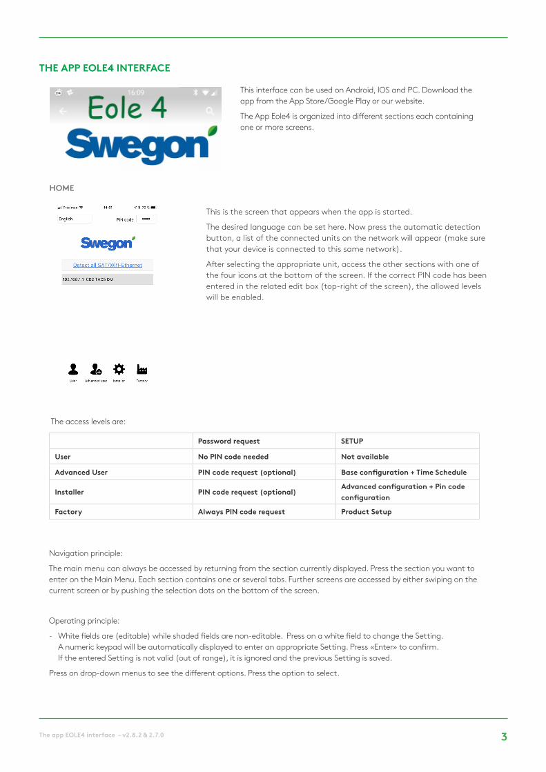
This is the screen that appears when the app is started.
The desired language can be set here. Now press the automatic detection button, a list of the connected units on the network will appear (make sure that your device is connected to this same network).
After selecting the appropriate unit, access the other sections with one of the four icons at the bottom of the screen. If the correct PIN code has been entered in the related edit box (top-right of the screen), the allowed levels will be enabled.
HOME
Navigation principle:
The main menu can always be accessed by returning from the section currently displayed. Press the section you want to enter on the Main Menu. Each section contains one or several tabs. Further screens are accessed by either swiping on the current screen or by pushing the selection dots on the bottom of the screen.
Operating principle:
- White fields are (editable) while shaded fields are non-editable. Press on a white field to change the Setting. A numeric keypad will be automatically displayed to enter an appropriate Setting. Press «Enter» to confirm. If the entered Setting is not valid (out of range), it is ignored and the previous Setting is saved.
Press on drop-down menus to see the different options. Press the option to select.
The access levels are:
This interface can be used on Android, IOS and PC. Download the app from the App Store/Google Play or our website.
The App Eole4 is organized into different sections each containing one or more screens.
THE APP EOLE4 INTERFACE
Password request SETUP
User No PIN code needed Not available
Advanced User PIN code request (optional) Base configuration + Time Schedule
Installer PIN code request (optional)Advanced configuration + Pin code configuration
Factory Always PIN code request Product Setup

4 The app EOLE4 interface – v2.8.2 & 2.7.0
STATUS BAR
COMMAND BAR
The first row includes, from left to right:
- an icon corresponding to the access level,
- the code ID of the unit as configured in the control board,
- identification of the current control mode indication:
• FATAL ERROR: Fans are stopped;
• FIRE ALARM;
• RC: remote control RC TAC5;
• EXTERNAL OPERATION: K1-K2-K3 contacts;
• AUTO: TIMESCHEDULER;
• BYPASS;
• BOOST;
• App
The status bar is visible in all sections and is made up of two rows of text and a status indicator.
The command bar is also visible in all sections and is used to control the unit at the selected address and contains a row of the following buttons, from left to right:
• Manual/Auto position: Choose between the automatic position with control according to time slots and the manual position with control via the fan buttons of this screen. The selection is made by pressing the icon.
• Fan speed selection button corresponding to electrical input K1-K2-K3. Only K1 and K3 buttons are available for LS and CP mode (see Setup context) where K1 is normal operation and K3 is a low operation rate (“Sleep factor”).
• Boost: if pressed, the boost is enabled (see advanced setup – boost). This icon has the same effect as electrical contact IN9.
• Bypass: if pressed, the bypass is totally enabled (see advanced setup – bypass). This icon has the same effect as electrical contact IN4.
• “Heating/Cooling” (if post-heating and/or post-cooling are installed): Choose between the heating mode/cooling mode/ Automatic changeover between heating and cooling (only if both post-heating and post-cooling are present)/ OFF mode (heating and cooling are stopped).
• Comfort Temperature Setpoint increase: the comfort T° setpoint is increased by 0.5°C after each time the icon is pressed.
• Comfort Temperature Setpoint decrease: the comfort T° setpoint is decreased by 0.5°C after each time the icon is pressed.
Figure 1 - Control bar in CA/TQ mode Figure 2 - Control bar in LS/CP mode
The second row includes, from left to right:
- Default alarm LED: red when default alarm is active (see Troubleshooting section)
- Pressure alarm LED: red when pressure alarm is active (see Troubleshooting section)
- AF LED: antifreeze status indicator. Red when antifreeze is active (see Troubleshooting section)
- Bypass LED: bypass status indicator (white: bypass inactive, orange: partially active, green: totally active)
- Com LED: communications status indicator (green: communications ok, red: communications fault, see communications context)
- Day of the week and hour from the control board.
- The operating time of the unit.
- The filters hours counter.
MAN
U/ A
UTO
K1 K2 K3 BOO
ST
BYPA
SS
HEA
T/ C
OO
L
T° +
0,5
°C
T° -
0,5
°C
MAN
U/ A
UTO
K1 K3 BOO
ST
BYPA
SS
HEA
T/ C
OO
L
T° +
0,5
°C
T° -
0,5
°C

5The app EOLE4 interface – v2.8.2 & 2.7.0
The screen displays a basic diagram of the unit containing useful information about the air handling unit. The screen automatically adapts depending on the status of the unit and the installed options.
It indicates:
• The inlet and outlet temperatures of each flow;
• The supply and extract flows;
• The different components installed in the unit and their current status (options: KWin, KWout, hot water battery NV);
• The different external components and their current status (options: SAT TAC5 BA/KW);
VISUALISATION
SETPOINTS
CONFIGURATION
In this section, the control mode and the Settings of the setpoints for the supply and exhaust fan(s) are displayed per the relative selected command (K1-k2-K3 contacts or icons).
The comfort temperature setpoint is also visible here provided that optional post-heating batteries are configured.
This section is not available on “User” level. It is used to configure the units and is divided into 3 sections selectable by the tab at the top of page: Base, Advanced and Factory (only for factory settings).
This tab allows the setting of the fan’s operating mode, the pressure alarm and the comfort temperatures (if post-heating or post-cooling or free cooling option are installed) on different screens which vary depending on the selected operating mode.
Select the desired operating mode in the selection box.
Setting is done via editable fields for these parameters:
The exhaust airflow is calculated automatically based on the Ratio Exhaust /Supply.
Base
Main Screen
Constant Airflow Mode (CA)
Ratio Exhaust /Supply
Enter the ratio (%) between exhaust (fans F3, F4) and supply (fans F1, F2) airflows
Airflow IEnter supply airflow 1. Enabled if contact between terminals K1 and + 12V is closed on TAC5 circuit, or if K1 button is selected on the control bar.
Airflow IIEnter supply airflow 2. Enabled if contact between terminals K2 and + 12V is closed on TAC5 circuit, or if K2 button is selected on the control bar.
Airflow IIIEnter supply airflow 3. Enabled if contact between terminals K3 and + 12V is closed on TAC5 circuit, or if K3 button is selected on the control bar.

6 The app EOLE4 interface – v2.8.2 & 2.7.0
Setting is done via editable fields for these parameters:
Setting is done via editable fields for these parameters:
The percentage of maximum fan torque for exhaust is calculated automatically based on the ratio Exhaust /Supply.
Constant torque Mode (TQ)
Demand control 0-10V Mode (LS)
Ratio Exhaust /Supply
Enter the ratio (%) between exhaust (fans F3, F4) and supply (fans F1, F2) airflows.
Torque IEnter percentage 1 of maximum fan torque for supply. Enabled if contact between terminals K1 and + 12V is closed on TAC5 circuit, or if K1 button is selected on the control bar.
Torque IIEnter percentage 2 of maximum fan torque for supply. Enabled if contact between terminals K2 and + 12V is closed on TAC5 circuit, or if K2 button is selected on the control bar.
Torque IIIEnter percentage 3 of maximum fan torque for supply. Enabled if contact between terminals K3 and + 12V is closed on TAC5 circuit, or if K3 button is selected on the control bar.
V min Enter Vmin for LS link (minimum voltage)
V max Enter Vmax for LS link (maximum voltage)
Flow @ Vmin Enter airflow rate corresponding to Vmin
Flow @ Vmax Enter airflow rate corresponding to Vmax (can be < or > to « flow ≡ Vmin »).
Stop fans if V<Vlow?
Possibility to stop the fans automatically if 0-10 V signal < Vlow. Press LED to turn this feature on (the LED turns green).
Vlow Appears only if the feature is enabled. Enter the threshold Setting Vlow (Vlow < Vmin).
Stop fans if V>Vhigh?
Possibility to stop the fans automatically if 0-10 V signal > Vhigh. Press LED to turn this feature on (the LED turns green).
Vhigh Appears only if the feature is enabled. Enter the threshold Setting Vhigh (Vhigh > Vmax).
0-10V on K3
“No”: Extract air volume equals supply air volume, if “Ratio Exhaust/supply” equals 100%“Yes”, “Exhaust”: Both air volumes are controlled independently by two different 0…10 V signals“Yes”, “Supply”: The most important of the two signals on K2 and K3 will be the master to control the supply air volume. The extract air volume equals supply air volume, if “Ratio Exhaust/supply” equals 100%
If 0-10V on K3 = NO
Ratio Exhaust /Supply
Select the airflow ratio between the exhaust airflow (fans F3, F4) and supply airflow (fans F1, F2)
% on K3 (sleep factor)
A “sleep factor”, where the unit enters a low operating rate. Enter multiplier (%) of the LS link when contact between terminals + 12V and K3 on TAC5 circuit is closed, or if K3 (Sleep) button is selected on the control bar.

7The app EOLE4 interface – v2.8.2 & 2.7.0
Setting is done via editable fields for these parameters:
Used in CA or LS mode to initialize the computed pressure alarm. Setting is done via editable fields for these parameters
This screen is visible only if there is post-heating or post-cooling or free cooling (with modulating bypass) installed. Setting is done via editable fields for these parameters
When automatic changeover is selected in the command bar and when there are post-heating and post-cooling:
Constant Pressure Mode (CP)
Alarm Pa Screen
T° Setpoint Screen
CP on« Supply » or « Exhaust » or « Supply and Exhaust ». Select in which airflow the pressure sensor is placed.
Ratio Exhaust/Supply
Enter the airflow ratio between the exhaust airflow (fans F3, F4) and supply airflow (fans F1, F2). Not applicable if CP on supply and exhaust.
% on K3 (sleep factor)
A “sleep factor”, where the unit enters a low operating rate. Enter multiplier (%) of the CP assignment when contact between terminals + 12V and K3 on TAC5 circuit is closed, or if K3 (Sleep) button is selected on the control bar.
Initialize the pres-sure
« Airflow » or « Pressure ». Specify method to determine the reference pressure.
If Init pressure VIA AIRFLOW: TAC5 control automatically computes setpoint pressure Setting
xx,x VLast registered pressure setpoint (0.0 if never configured). Non-editable in this type of initialization. To edit it directly, switch to manual initialization.
xxxx m³/h Enter (nominal) airflow at which the pressure setpoint must be determined.
StartMake sure that the panels of the unit are fully closed, with filters in place. Press "Start" to start initialization of Pa ref (optional if been made previously).
If MANUAL Init pressure: enter pressure setpoint directly
xx,x VEnter pressure setpoint Setting (converted in voltage according to the pressure sensor characteristics).
Pressure alarm Pressure alarm is optional. To activate the pressure alarm, press the enabling button.
Reference SettingsSupply/Exhaust
Reference pressure (Pa ref) determination. Pa ref is defined by running the supply and exhaust fans at airflows specified below (exhaust airflow is determined by the «%Ex/Su» ratio. Pa ref for supply and exhaust are consequently different.
Maximum pressure variation Supply/Exhaust
Setup Pa Alarm on supply and exhaust side. Enter pressure increment (corresponding to the additional pressure desired to reach the reference pressure on each side)
Resulting alarm threshold
Make sure that the panels of the unit are fully closed, with filters in place. Press « Initialization» to start initialization of Pa ref (optional if been made previously).
Heating Enter comfort setpoint T° for heating
Cooling Enter comfort setpoint T° for cooling
Free cooling Enter comfort setpoint T° for free cooling
Comfort Comfort setpoint T°
Neutral band highSelect the higher neutral band respect to the desired comfort setpoint. A change over from heat to cool will automatically occur when the measured temperature on the extract air will exceed this band.
Neutral band lowSelect the lower neutral band respect to the desired comfort setpoint. A change over from cool to heat will automatically occur when the measured temperature on the extract air will fall under this band.

8 The app EOLE4 interface – v2.8.2 & 2.7.0
Airflow units Choice of airflow unit: m³/h (default) or l/s
Start torque Possibility to modify the fan’s starting torque (2% default).
Softstop allowed
Disable the possibility to stop the fans using the RC (remote control) via K1/K2/K3 on TAC5 circuit. This feature corresponds to disabling the softstop function: - If GRC master: the OFF key is disabled.- If TAC5 master: SAME COMMENT AS BEFORE-CA mode: if no entries connected to K1/K2/K3 then K1 airflow is activated.- LS or CP Mode: if K1 entry is not connected to +12 V, then control operates as if K1 was connected to +12V.
To do this select N (Y is default Setting)
OUT1 (0-10V)Choice of information supplied by 0-10 V OUT1 output connection: airflow/torque or pressure on one fan (default Setting is airflow/torque on fan F1).
OUT2 (0-10V)Choice of information supplied by 0-10 V OUT2 output connection: airflow/torque or pressure on one fan (default Setting is pressure on fan F1).
Parameter used only in CP mode
Reaction speed in CP
Configuration of the reaction speed of the CP algorithm. 10 is the default Setting and is the highest reaction speed. Each -1 increment corresponds to a doubling of the reaction time (10 = T, 9 = 2xT, 8 = 4xT,...). The default Setting is determined for most ducting applications, only special applications (e.g. constant pressure in a room) require changing this parameter.
Reaction logic in CP
Configuration of CP mode operating logic:
- Negative logic:
• airflow rate drops when signal on K2 > assignment Setting • airflow rate rises when signal on K2 < assignment Setting
- Positive Logic:
• airflow rate rises when signal on K2 > assignment Setting
• airflow rate drops when signal on K2 < assignment Setting
This tab in the configuration section is used to enable specific features or to modify standard settings.
Select the desired operating mode in the selection box.
Advanced
Main Screen
This screen can be used to set the desired number of hours to be alerted for the filters cleaning or replacing. This hours should be set taking into account the recommendation of the preventive maintenance section. Once the filters cleaned or replaced, the hours counter must be reset with the button.
Filters Hours Menu
Maximum Filters Hours
Set the hours after which to change or clean the filters. Refer to the preventive maintenance section. If the Setting configured will be higher than 0, then an alarm message requiring to change or clean the filter will appear when the counter of the filters hours will exceed this parameter.
Reset hoursButton for resetting the counter for the filters hours. To do when then filters have been cleaned or changed

9The app EOLE4 interface – v2.8.2 & 2.7.0
Stop fans if alarm Pa
Possibility to stop the fans in case of pressure alarm (after cancelling the alarm, press RESET to restart the fans).
Fire alarm Type of contact
Select how the fire alarm is activated: entry IN3 is N.O or N.C (normally open or normally closed)NO: alarm is activated when in3 contact closedNC: alarm is activated when in3 contact is openSee Troubleshooting section – Fire alarm.
Fire alarm – SupplyEnter supply airflow rate when fire alarm is activated and if contact IN7 is closed. See Troubleshooting section – Fire alarm
Fire alarm Exhaust
Enter exhaust airflow rate when fire alarm is activated and if contact IN8 is closed. See Troubleshooting section – Fire alarm
Reset This button resets the operating time counter to 0
Show fan runtime Enable display of operating time
Service alarm Enable maintenance alarm after a certain operating time
Xxxxh Enter operating time limit (in hours) to generate a maintenance alarm.
Stop fan Enable ‘fan stop’ alarm after a certain operating time?
XxxxhEnter operating time limit (in hours) to generate a ‘fan stop’ alarm. The fans will be stopped after this limit is passed.
This screen is dedicated to special features configuration concerning the alarms management. It contains the following editable fields that permit to change the associated parameter:
This screen is dedicated to the settings of the fan runtime function: possibility to enable a fan operating time counter feature. The purpose is to report a maintenance alarm and/or to stop the fans after a certain time of operation. The function will be enabled if at least one of the 2 operating time features is enabled.
The screen contains the following editable fields:
Main Screen
Fan runtime Screen

10 The app EOLE4 interface – v2.8.2 & 2.7.0
This screen is dedicated to the bypass configuration. It contains the following editable fields that permit to change the associated parameter:
Bypass Screen
T1 - T2
Possibility to modify T° setpoints to control opening/closing the bypass.
• Open bypass if all following conditions are met:
Outdoor T° (T1) < indoor T° (S2). Outdoor T° (T1) > T1. Indoor T° (T2) > T2.
• Closing bypass if one of the conditions is met:
Outdoor T° (T1) > T° indoor (S2). Outdoor T° (T1) < T1 - 1°C. Indoor T° (T2) < T2 - 2°C.
Impose airflow if bypass open
Enter supply and exhaust airflow rates (or percentages of maximum fan torque if torque modulation instead of airflow) when bypass is open. If you select Y, then the airflows/torques are independent from the airflows/torques when bypass is closed (Closed bypass airflows/torques, are function of operating mode, K1, K2, K3 status or Modbus commands).
Supply Enter supply airflow rate when bypass open.
Exhaust Enter exhaust airflow rate when bypass open.
%Bypass mode
If modulating bypass type (not available for all-or-nothing type):Modality of modulating bypass:- FREECOOL: free cooling due to the modulation of the bypass opening according to the difference between the measured T° in the supply duct (T5) and the free cooling setpoint temperature configured in base setup.-A-FREEZE: frost protection of the plate heat exchanger due to the modulation of the bypass opening to keep the T° of the exhaust air at the exchanger output (T3) above AF REC setpoint (see below).- AF-FREEC: combines the functions of FREECOOL and A-FREEZE
11The app EOLE4 interface – v2.8.2 & 2.7.0
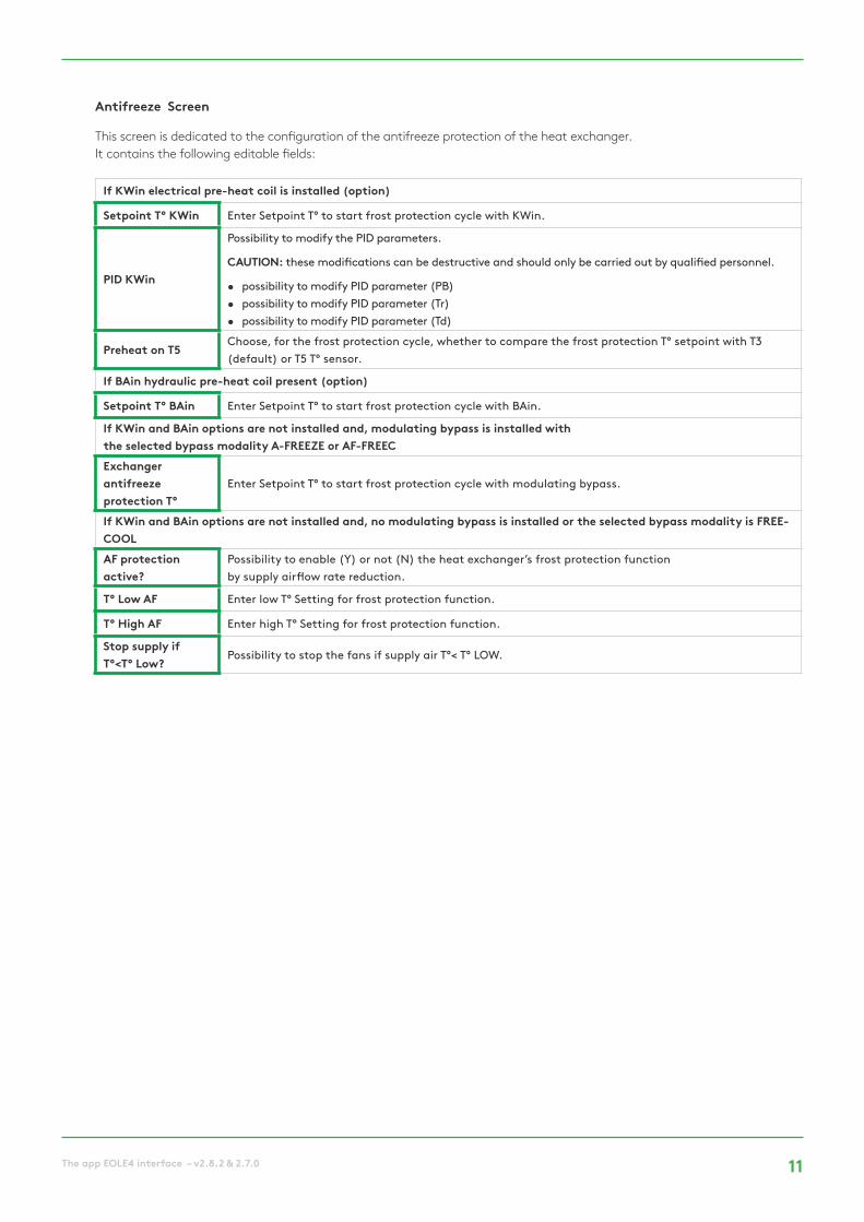
If KWin electrical pre-heat coil is installed (option)
Setpoint T° KWin Enter Setpoint T° to start frost protection cycle with KWin.
PID KWin
Possibility to modify the PID parameters.
CAUTION: these modifications can be destructive and should only be carried out by qualified personnel.
• possibility to modify PID parameter (PB) • possibility to modify PID parameter (Tr) • possibility to modify PID parameter (Td)
Preheat on T5Choose, for the frost protection cycle, whether to compare the frost protection T° setpoint with T3 (default) or T5 T° sensor.
If BAin hydraulic pre-heat coil present (option)
Setpoint T° BAin Enter Setpoint T° to start frost protection cycle with BAin.
If KWin and BAin options are not installed and, modulating bypass is installed with the selected bypass modality A-FREEZE or AF-FREEC Exchanger antifreeze protection T°
Enter Setpoint T° to start frost protection cycle with modulating bypass.
If KWin and BAin options are not installed and, no modulating bypass is installed or the selected bypass modality is FREE-COOLAF protection active?
Possibility to enable (Y) or not (N) the heat exchanger’s frost protection function by supply airflow rate reduction.
T° Low AF Enter low T° Setting for frost protection function.
T° High AF Enter high T° Setting for frost protection function.
Stop supply if T°<T° Low?
Possibility to stop the fans if supply air T°< T° LOW.
This screen is dedicated to the configuration of the antifreeze protection of the heat exchanger. It contains the following editable fields:
Antifreeze Screen

12 The app EOLE4 interface – v2.8.2 & 2.7.0
Post-ventilation
Enable post-ventilation function (allow fans to run during a certain period after softstop is enabled). Caution: if KWin and/or KWout, and/or SAT BA/KW is installed, the post-ventilation function is auto-matically enabled. It is then impossible to set it to ‘NO’.If enabled, enter post-ventilation time (in seconds).
STOP FAN IF T5<5°C
Possibility to stop the fan if the supply air temperature falls below 5°C (only if temperature sensor T5 is wired)
PID KWout
With KWout/KWext option: Possibility to modify the PID parameters.
CAUTION: these modifications can be destructive and should only be carried out by qualified personnel.
• possibility to modify PID parameter (PB) • possibility to modify PID parameter (Tr) • possibility to modify PID parameter (Td)
Sat BASelect coil type(s) regulated by the SAT BA/KW: BA+, BA-, BA+/-, BA+/BA-, KW, BA-/KW, BAin, BAin/BA+, BAin/BA+-, KW 0-10V, KW 10/BA-
NV / BA+ Speed
If NV or BA+ is installed:Possibility to change the reaction speed configuration of the post heating algorithm (3-way valve control). Default Setting ‘5’ Each increment of -1 corresponds to a doubling of the reaction time (‘5’=T, ‘4’=2xT, ‘3’=4xT, ‘2’=8xT, …).Each increment of +1 corresponds to a halving of the reaction time (‘5’=T, ‘6’=T/2, ‘7’=T/4, ‘8’=T/8, …).We recommend changing this Setting only if you experience T° stability problems in your application.
Antifreeze T° NV/BA+
If NV or BA+ is installed:Temperature threshold for NV/BA+ frost protection: if the temperature of NV/BA+ drops below this threshold, then the frost protection for NV/BA+ will be activated.
BA- Speed
If BA- installed:Possibility to change the reaction speed configuration of the post cooling algorithm (3-way valve control). Default Setting ‘5’ Each increment of -1 corresponds to a doubling of the reaction time (‘5’=T, ‘4’=2xT, ‘3’=4xT, ‘2’=8xT, …).Each increment of +1 corresponds to a halving of the reaction time (‘5’=T, ‘6’=T/2, ‘7’=T/4, ‘8’=T/8, …).We recommend changing this Setting only if you experience T° stability problems in your application.
Antifreeze T BA-If BA- is installed:Temperature threshold for BA- or BAin frost protection: if the temperature of BA-/BA in drops below this threshold, then the frost protection for BA-/BAin will be enabled.
COMFORT ON T5In the post-heating or post-cooling coil(s) are installed, possibility to change if r T° is measured on supply (T5) or exhaust / room (T2). The temperature measured on the selected sensor is used to determine the deviation from the setpoint for regulating the heating or cooling power.
If comfort on T2
SpeedConfiguration of the reaction speed of post-heating/cooling. 8 default. Each -1 increment slows down and corresponds to a doubling of the reaction time (8 = T, 7 = 2xT, 6 = 4xT,...).Each +1 increment speeds up and corresponds to a diving of the reaction time (8 = T, 9 = T/2, 10 = T/4).
Min/Max Supply T°Lower limit of supply air (T5). Upper limit of supply air (T5).
This screen is dedicated to the configuration of the post-heating and/or post-cooling batteries either internal in the unit or external. It contains the following editable fields that permit associated parameters to be changed:
KW/BA Screen

13The app EOLE4 interface – v2.8.2 & 2.7.0
Unit name Name of the AHU to be easily identified during detection or in a network.
Advanced user access protected
Available only for advanced user access level. If enabled, possibility to enter a PIN code for the access level as advanced user.
Installer access protected
Available only for installer access level. If enabled, possibility to enter a PIN code for the access level as installer.
Factory PIN Available only for factory.
High Select High to enable high level access and to edit its code. This level will give full access.
Reset to factory settings
Possibility to operate a general factory reset. All factory settings are then regenerated.
This screen contains the following editable fields that permit associated parameter to be changed:
Antifreeze Screen
TIMETABLE
The Timetable section is used to program the operating mode and the setting points for the fans, the comfort temperature and the status of the bypass on a weekly basis. Seasonal management of the bypass and the cold and hot coils is provided under the Year Planner tab.
The first tab of this section allows the user to change the time and date of the control board if necessary. A button automatically synchronises the time and date with the device which is running the App.
This tab also allows the user to configure the LS or CP mode, if these will be used in the timetable and the basic setup has been done with a CA or TQ Mode. Swipe to the second or third screen to perform the configuration of LS and CP respectively as described in the Setup section.
Setup
Week Planner
The time slots feature allows configuration of six time slots. per day. For each time slot, the operating mode and the setpoint must be configured.
To configuring a schedule:
• Select the desired day of the week from Monday to Sunday.
• Select the desired time slot from 1 to 6.
• Indicate the start time of the time slot.
• Select the operating mode.
• Enter ‘basic’ setup multiplier if LS or CP, or constant airflows (exhaust and supply) if CA mode, or constant torques (exhaust and supply) if TQ mode.
• Enter exhaust/supply ratio if LS or CP mode
• Specify if bypass is in automatic mode, open or closed.
• Specify T° setpoints in case of post-heating or post cooling (if option present).
• Once the time slots for one of the week days have been configured, the button Copy will permit, if so desired, to copy the time slot configuration for that day to the following days.

14 The app EOLE4 interface – v2.8.2 & 2.7.0
DIAGNOSTICS
COMMUNICATIONS
NETWORK
This section is useful for troubleshooting thanks to the following screens:.
This section provides the ability to configure the IP address manually and the communications port for connection to the desired unit. A button for automatic detection is also available.
Note that if the unit is accessed remotely through a VPN, automatic detection cannot work and initial access must be done in this screen providing the correct IP address and communications port.
Finally, a check box for automatic connection to the last connected unit allows access directly to the unit the next the App is started up. The discovery phase will be skipped and the visualisation context will be immediately entered with the User access level.
The App Eole4 can control a network of units and, in this instance, the screen automatically shows an overview of the status of all the connected AHU with a row for each one containing:
• The IP address of the unit and its name, provided it has been configured.
• The operating mode of the unit (CA, TQ, LS, CP).
• The flows Settings: supply and extract airflows with pressures (these ones are always available for forward fans type, but only with option kit CA for backward fans type).
• The alarm status of the unit.
To interface directly with one of these units, just select its row and then press the connect button.
This screen shows the airflow and the computed pressure for each fan (the pressure is always available for forward fans type, but only with option kit CA for backward fans type).
Alarms
In this screen, the Settings of the temperature sensors are displayed.
T°
This screen gives the description of the active alarms with a button to reset. In CP mode and when Modbus sensors are used, the related pressure is displayed in this screen also.
Flows
The Settings and status of the Input/output can be monitored here.
I/O
Year Planner
The screen of the Year Planner section allows the configuration to be adapted according to the time of year:
• Specify whether to disable the bypass (press button and introduce period)
• Specify whether to disable the post-heating (press button and introduce period)
• Specify whether to disable the cooling coil (press button and introduce period).
VERSION INFO
This screen gives the software version number of the App, of the SAT WIFI or Ethernet and of the control board TAC5.

15The app EOLE4 interface – v2.8.2 & 2.7.0

We make every breath count.
Version: 02.12.2017
We reserve the right for changes.