application description 01/2014 quality assurance … assurance through weighing, controlling and...
TRANSCRIPT

http://support.automation.siemens.com/WW/view/en/82454336
Application Description 01/2014
Quality assurance through weighing, controlling and logging (Set 6) SIMATIC S7-1200 + SIWAREX WP231

Warranty and liability
Quality Assurance by means of Weighing, Control and Logging (Set 6) Entry ID: 82454336, V1.0, 01/2014 2
S
iem
ens
AG 2
014
All r
ight
s re
serv
ed
Warranty and liability
Note The Application Examples are not binding and do not claim to be complete regarding the circuits shown, equipping and any eventuality. The Application Examples do not represent customer-specific solutions. They are only intended to provide support for typical applications. You are responsible for ensuring that the described products are used correctly. These application examples do not relieve you of the responsibility to use safe practices in application, installation, operation and maintenance. When using these Application Examples, you recognize that we cannot be made liable for any damage/claims beyond the liability clause described. We reserve the right to make changes to these Application Examples at any time without prior notice. If there are any deviations between the recommendations provided in these application examples and other Siemens publications – e.g. Catalogs – the contents of the other documents have priority.
We do not accept any liability for the information contained in this document.
Any claims against us – based on whatever legal reason – resulting from the use of the examples, information, programs, engineering and performance data etc., described in this Application Example shall be excluded. Such an exclusion shall not apply in the case of mandatory liability, e.g. under the German Product Liability Act (“Produkthaftungsgesetz”), in case of intent, gross negligence, or injury of life, body or health, guarantee for the quality of a product, fraudulent concealment of a deficiency or breach of a condition which goes to the root of the contract (“wesentliche Vertragspflichten”). The damages for a breach of a substantial contractual obligation are, however, limited to the foreseeable damage, typical for the type of contract, except in the event of intent or gross negligence or injury to life, body or health. The above provisions do not imply a change of the burden of proof to your detriment. Any form of duplication or distribution of these Application Examples or excerpts hereof is prohibited without the expressed consent of Siemens Industry Sector.
Security informa-tion
Siemens provides products and solutions with industrial security functions that support the secure operation of plants, solutions, machines, equipment and/or networks. They are important components in a holistic industrial security concept. With this in mind, Siemens’ products and solutions undergo continuous development. Siemens recommends strongly that you regularly check for product updates.
For the secure operation of Siemens products and solutions, it is necessary to take suitable preventive action (e.g. cell protection concept) and integrate each component into a holistic, state-of-the-art industrial security concept. Third-party products that may be in use should also be considered. For more information about industrial security, visit http://www.siemens.com/industrialsecurity.
To stay informed about product updates as they occur, sign up for a product-specific newsletter. For more information, visit http://support.automation.siemens.com.

Table of Contents
Quality Assurance by means of Weighing, Control and Logging (Set 6) Entry ID: 82454336, V1.0, 01/2014 3
S
iem
ens
AG 2
014
All r
ight
s re
serv
ed
Table of Contents Warranty and liability ................................................................................................... 2
1 Task ..................................................................................................................... 5
1.1 Overview............................................................................................... 5 2 Solution............................................................................................................... 7
2.1 Overview............................................................................................... 7 2.2 Hardware and software components ................................................... 9 2.2.1 Validity .................................................................................................. 9 2.2.2 Components used ................................................................................ 9
3 Basics ............................................................................................................... 11
3.1 Recording weight as measured variable and providing as value ....... 11 3.2 Recipe management .......................................................................... 12 3.3 Filling goods ....................................................................................... 13 3.4 Logging the quality inspection ............................................................ 14 3.5 Automated archiving of the log data ................................................... 15
4 Mode of Operation ........................................................................................... 16
4.1 Program overview .............................................................................. 16 4.2 SIWAREX blocks ................................................................................ 16 4.2.1 Function block “WP23PE” .................................................................. 16 4.2.2 Data block “DB_Scale” ....................................................................... 18 4.3 User program blocks .......................................................................... 19 4.3.1 “Teach” function block ........................................................................ 19 4.3.2 “Filling” function block ......................................................................... 21 4.3.3 “HMI” function block ........................................................................... 24 4.3.4 “Tags” data block ................................................................................ 26 4.4 Data logging blocks ............................................................................ 27 4.4.1 “Copy” function ................................................................................... 27 4.4.2 “DataLog” function block .................................................................... 29 4.4.3 “Time” function ................................................................................... 31
5 Configuration and Settings............................................................................. 33
5.1 Configuring SIMATIC Panel TP700 Comfort...................................... 33 5.2 Network connections .......................................................................... 34 5.2.1 Setting PG/PC Interface ..................................................................... 36 5.3 Regional and language options .......................................................... 36 5.4 Configuring SIWAREX WP231 weighing module .............................. 37
6 Installation and Commissioning .................................................................... 41
6.1 Hardware installation .......................................................................... 41 6.2 Installation of the software (download) ............................................... 42 6.3 Downloading the Startup Code .......................................................... 43
Loading configuration of the weighing module ................................... 43 Downloading the TIA Portal project .................................................... 44
7 Operating the Application ............................................................................... 45
7.1 Overview............................................................................................. 45 7.1.1 Toolbar (footer) ................................................................................... 45 7.1.2 Header with scale status .................................................................... 46 7.2 Commissioning ................................................................................... 47 7.2.1 Setting time ........................................................................................ 47 7.2.2 Recalibrating ...................................................................................... 48 7.3 Live demo ........................................................................................... 49 7.3.1 Recipe ................................................................................................ 49
Table of Contents
Quality Assurance by means of Weighing, Control and Logging (Set 6) Entry ID: 82454336, V1.0, 01/2014 4
S
iem
ens
AG 2
014
All r
ight
s re
serv
ed
7.3.2 Filling process .................................................................................... 50 7.3.3 DataLog .............................................................................................. 52 7.3.4 Reading out the DataLog file .............................................................. 53
8 Literature .......................................................................................................... 55
9 History............................................................................................................... 56

1 Task 1.1 Overview
Quality Assurance by means of Weighing, Control and Logging (Set 6) Entry ID: 82454336, V1.0, 01/2014 5
S
iem
ens
AG 2
014
All r
ight
s re
serv
ed
1 Task 1.1 Overview
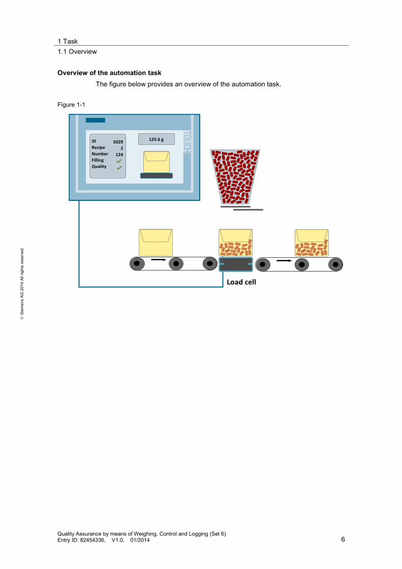
In the packaging industry, containers are to be filled with a specified number of pieces (e.g. of wall dowels), calculated by weight control. Before the actual filling, it can be selected via a recipe selection, what (which dowel diameter) and how many are to be filled. Apart from the allowed weight tolerance for the goods filled, the recipe also includes the individual weight of a dowel. A teach function, can determine this, based on the arithmetic average of a counted sample, and this can be saved in the recipe. The packaging weight is tared to 0. The filling process opens two sliders. One opens/closes the storage container with the goods to be filled. The second limits the filling speed (fast/slow). When reaching the specified threshold (e.g. 90% of the weight setpoint) the filling speed is lowered by the second slider. This prevents overfilling. When the calculated weight setpoint (pieces x individual weight) is reached, the second slide is also closed and filling is completed. Underfilling is not permissible. Subsequently, a quality assessment is to take place. The packaged goods will pass the quality control if the filling weight is within the tolerance specified, it not, it will not pass. In the course of this quality assurance measure the goods are to be clearly identified and all relevant data, including time stamp are to be logged. It shall be possible to import the log data to Office Excel. The automation of the logging process and the integration of the required components into the existing infrastructure of the packaging system are to be possible. It must be possible to apply the check for completeness of the packaged goods also to other products with different content without extra work. The packaging system is to be operated and maintained exclusively via an HMI device. Operation is to be possible in German and English.
1 Task 1.1 Overview
Quality Assurance by means of Weighing, Control and Logging (Set 6) Entry ID: 82454336, V1.0, 01/2014 6
S
iem
ens
AG 2
014
All r
ight
s re
serv
ed
Overview of the automation task The figure below provides an overview of the automation task.
Figure 1-1
IDRecipeNumberFillingQuality
50292
124
125.6 g
Load cell

2 Solution 2.1 Overview
Quality Assurance by means of Weighing, Control and Logging (Set 6) Entry ID: 82454336, V1.0, 01/2014 7
S
iem
ens
AG 2
014
All r
ight
s re
serv
ed
2 Solution 2.1 Overview
Schematic layout The following figure gives a schematic overview of the most important components of the solution:
Figure 2-1
6
1 S7-1200 Power supply 3 S7-1200 CPU
5 SIWAREX WL 260
6 TP 700 comfort
4 SIWAREX WP 2312 CSM 1277
1 2 3 4
5
The automation solution uses an S7-1200 controller and the SIWAREX MS weighing module WP231 with WL260 load cell. The weight value of the goods to be filled is recorded and compared with a reference value. After filling, it is checked whether all components are complete. The packaged goods can be clearly identified by a batch number. The DataLog function of the S7-1200 controller makes it possible to log the currently measured weight values with a time stamp in the flash memory of the CPU. You can download your data log files with the help of an internet browser (e.g. the integrated internet explorer on the TP 700 Comfort TouchPanel) via the integrated PLC web server of the S7-1200 controller. Connecting the S7-1200 controller to a Windows PC makes enables automatic read out the log data and the evaluation with common spreadsheet applications such as Excel. Using a TP 700 Comfort touch panel, the currently running filling process can be monitored by screens that can be switched to German or English. The recipes to manage the reference data of different production series are saved in the Comfort Panel.

2 Solution 2.1 Overview
Quality Assurance by means of Weighing, Control and Logging (Set 6) Entry ID: 82454336, V1.0, 01/2014 8
S
iem
ens
AG 2
014
All r
ight
s re
serv
ed
Fields of application Set 6 is suitable for many industrial applications in which cost-effective weight measurements have to be performed with little engineering overhead. This set is particularly suitable if additionally automated logging functions are required in the framework of the measurement. Set 6 is particularly suitable for the following sectors and fields of application: • Food industry • Packaging industry • Raw materials • Machine industry
Advantages • The integration of the SIWAREX WP231 weighing module into the S7-1200
ensures that the technological functions of the weighing module are combined with all advantages of the PLC world (expansion capability, flexibility, software, HMI, drives, communication interfaces, etc.)
• Inexpensive weight measurement with high precision due to SIWAREX load cell
• Fast and simple configuration via TIA Portal V12 SP1 • Automated logging functions as proof for customers • Simple integration into existing systems by connecting via PROFINET
Delimitation This application focuses on the filling process by means of weighing technology, the recipe management via HMI and the data logging in the controller. The filling process is deliberately kept simple and is realized via the digital control of two sliders. When controlling an analog valve the program code has to be adjusted accordingly. This application does not contain a description of: • Positioning of the filling container (delivery and forwarding)
Required knowledge Basic knowledge of SIMATIC S7-1200 and the TIA Portal is assumed.

2 Solution 2.2 Hardware and software components
Quality Assurance by means of Weighing, Control and Logging (Set 6) Entry ID: 82454336, V1.0, 01/2014 9
S
iem
ens
AG 2
014
All r
ight
s re
serv
ed
2.2 Hardware and software components
2.2.1 Validity
This application is valid for • STEP 7 V12 SP1 (\9\) Update 2 (\11\) • WinCC Comfort V12 SP1 (\10\) Update 2 (\11\) • CPU 1214C Firmware V3.02 (\12\) • SIWAREX WP231 Firmware V1.0.3 (\5\)
2.2.2 Components used
The application was set up with the following components:
Hardware components Table 2-1
Component No. Order number Note
Power supply PM 1207 1 6EP1332-1SH71 Supplies the components with DC 24V
CSM 1277 1 6GK7277-1AA10-0AA0 Ethernet switch CPU 1214C DC/DC/DC 1 6ES7214-1AG31-0XB0 S7-1200 controller
Firmware: V3.0.2
SIWAREX WP 231 1 7MH4960-2AA01
Weighing module Firmware: V1.0.3
SIWAREX WL 260 load cell 1 7MH5102-1KD00
Rated load: 3 kg
SIMATIC HMI TP900 Comfort
1 6AV2124-0GC01-0AX0 Control panel
Accessorial equipment Table 2-2
Component No. Order number Note SIMATIC NET INDUSTRIAL ETHERNET TP CORD RJ45/RJ45, CAT 6, TP CABLE 4X2, PREASSEMBLED W. W. 2 RJ45 CONNECTORS, … 0.5M 1M 2M 6M 10M
4 6XV1870-3Q… …E50 …H10 …H20 …H60 …N10
Ethernet cable
Standard 35 mm DIN rail 1 6ES5 710-8MA11 483 mm

2 Solution 2.2 Hardware and software components
Quality Assurance by means of Weighing, Control and Logging (Set 6) Entry ID: 82454336, V1.0, 01/2014 10
S
iem
ens
AG 2
014
All r
ight
s re
serv
ed
Software components Table 2-3
Component No. Order number Note
STEP 7 Basic V12 SP1
1 6ES7822-0AA02-0YA5
Configuring and programming of the SIMATIC S7-1200
WinCC Comfort V12 SP1
1 6AV2101-0AA02-0AA5
Configuring and programming of the TP 700 Comfort
SIWATOOL V7 Configuration package
1 7MH4960-2AK01
PC configuration software for the SIWAREX WP 231 weighing module
Sample files and projects The following list includes all files and projects that are used in this example. Table 2-4
Component Note
82454336_S7-1200+SIWAREX_Set6_CODE_v1d0.zip
This zip file contains the TIA Portal project.
82454336_SIWAREX_WP231_V103_7MH5102-1KD00.zip
This zip file includes the SIWATOOL configuration for the load cell used.
82454336_S7-1200+SIWAREX_Set6_DOKU_v1d0_en.pdf
This document.

3 Basics 3.1 Recording weight as measured variable and providing as value
Quality Assurance by means of Weighing, Control and Logging (Set 6) Entry ID: 82454336, V1.0, 01/2014 11
S
iem
ens
AG 2
014
All r
ight
s re
serv
ed
3 Basics 3.1 Recording weight as measured variable and providing
as value Table 3-1
No. Function Comments
1. The SIWAREX WL260 load cell is used to convert a mechanical force into an electrical signal. Four expansion measuring strips (EMS) interconnected to a Wheatstone bridge, are attached to the spring rod of the load cell.
2. If a force acts upon the spring rod and
compresses or stretches the expansion measuring strips attached to it, an overall misalignment of the spring rod can be determined from the positive and negative changes in resistance. (Measurement voltage, proportional to change in resistance)
3. With the aid of the analog-digital converter
integrated in the SIWAREX WP231 weighing module, a weight value is continuously calculated from the measurement voltage. F
Measuring signal
10 ms
Weightvalue
2300 g
4. The S7-1200 controller accesses this weight
value via the backplane bus in the analog input address area of the WP231 weighing module. The transferred value is a 16-bit integer value. The “WP23PE” function block is used for the conversion into the respective weight value as floating point number. The weight value to be used is stored in the “DB_SCALE” data block.
Weight value
WP23PE
DB_SCALE
Prinzipdarstellung einer Wheatstone - Bridge
DMS (gestreckt) DMS (gestaucht)
DMS (gestreckt)
DMS (gestaucht)
Prinzipdarstellung einer Wheatstone - Bridge Basic diagram of a
Wheatstone - bridge
DMS (stretched) DMS (compressed)
DMS (stretched)
DMS (compressed)
belasteter Biegestab gestauchter DMS
gestreckter DMS
gestreckter DMS
gestauchter DMS
Stressed bending arm compressed DMS
stretched DMS
stretched DMS
stretched DMS

3 Basics 3.2 Recipe management
Quality Assurance by means of Weighing, Control and Logging (Set 6) Entry ID: 82454336, V1.0, 01/2014 12
S
iem
ens
AG 2
014
All r
ight
s re
serv
ed
Note The real addressing can be read out via the device view of the SIWAREX WP231 weighing module in the “I/O addresses” menu item in STEP 7 V12 Basic.
3.2 Recipe management Table 3-2
No. Function Comments
1. Within the framework of the configuration, the goods to be filled are selected with the help of the recipe management. In the example project a recipe (“dowels”) has been created. The recipe consists of 4 elements: • Diameter of the dowel to be filled • Individual weight of a dowel • Quantity (number of the dowels to be
filled) • Tolerance in gram
2. 3 recipe data records are predefined and stored in the Comfort Panel. • 200 dowels with a diameter of 4mm • 100 dowels with a diameter of 6mm • 50 dowels with a diameter of 8mm
3. The recipe to be filled can be selected via the data record no. In addition, there is the option to weigh a counted sample of dowels via the "teach” function. The detected weight is divided by the pieces specified and thus the arithmetic average is calculated and written into the recipe data record as new individual weight of a dowel. The weight to be filled can be calculated via the pieces and the individual weight. The tolerance is decisive for the later quality assessment of the filled product.

3 Basics 3.3 Filling goods
Quality Assurance by means of Weighing, Control and Logging (Set 6) Entry ID: 82454336, V1.0, 01/2014 13
S
iem
ens
AG 2
014
All r
ight
s re
serv
ed
3.3 Filling goods Table 3-3
No. Function Comments
1. Once the product to be filled is selected via the recipe data record, the setpoint weight is calculated in the CPU and filling is started via the digital control of the two sliders. During the filling process the actual weight is compared with the setpoint weight, with the help of the load cell and the weighing module. When a specified threshold has been reached (e.g. 90% of the setpoint weight) the filling speed is reduced via the slide control. When the setpoint has been reached, the sliders are closed.
0,4
Recipe
Digitalcontrol
2. After filling, the filled weight is evaluated for
quality assurance. The weight value for a positive evaluation has be within the following limits: • Setpoint weight + resolution of the load
cell • Setpoint weight + resolution of the load
cell + tolerance If the real weight value of the product is in the tolerance range of the requirements, the quality of the current product is assessed as good. An underfilling is therefore not possible.
(a) Setpoint weight: e.g. 200 g(b) Resolution: 0.2 g (c) Tolerance: + 10 g(d) Real weight: 205 g
195 200 205 210 215
205200.2
Tolerance range (quality good)
g
a+bd
a+b+c=210.2
3. Each filled product is counted. The continuous
numbering, for example, can be linked with the product via a labeling machine. This is how the product (e.g. via barcode scanner) can be traced. The product can later also be clearly identified via this ID.
?205 g
4. After completing the quality inspection, the result of the quality inspection is assigned to the product ID.
Quality status: • 0 (poor) • 1 (good)

3 Basics 3.4 Logging the quality inspection
Quality Assurance by means of Weighing, Control and Logging (Set 6) Entry ID: 82454336, V1.0, 01/2014 14
S
iem
ens
AG 2
014
All r
ight
s re
serv
ed
3.4 Logging the quality inspection Table 3-4
No. Function Comments
1. Within the configuration, the logging is executed with the help of the “Data Log” functionality of the flash memory of the S7-1200. Each data log entry includes the following data: • Recipe ID • Diameter of the dowel to be filled • Individual weight of a dowel • Quantity (number of the dowels to be
filled) • Tolerance in gram • Total weight measured • Quality of the filling (good/poor) • Product ID (Package no.)
2. Logging is performed with the help of the “DataLog” function block, once filling and quality check of the product has been completed. DataLog
205 g
3. When the logging process is started, the FB
“DataLog” writes the current values into the flash memory of the CPU 1214C. With every call, a new data record is added to the already existing log data. The size of the log file is specified with 1000 data records before the oldest is overwritten. (Ring buffer)
• When creating the log file (first call of “DataLog” FB) its size can be specified (memory capacity of the flash memory assumed).
• In addition, a date and time stamp is stored for each data record.

3 Basics 3.5 Automated archiving of the log data
Quality Assurance by means of Weighing, Control and Logging (Set 6) Entry ID: 82454336, V1.0, 01/2014 15
S
iem
ens
AG 2
014
All r
ight
s re
serv
ed
3.5 Automated archiving of the log data
Archiving the log data Table 3-5
No. Function Comments
1. The log data can be exported from the flash memory onto the local hard disk of a Window PC with the help of an internet browser via the integrated web server of the S7-1200 and can be saved as CSV file1 .
2. The “Scheduled Tasks” standard function in
MS Windows enables to automate the archiving of the log data via the internet browser (e.g. Mozilla “Firefox”) at freely definable intervals.
1 A CSV file is an ASCII file for saving or exchanging simple structured data. The abbreviation CSV stands for Character Separated Values, since the individual values are separated by a special separator. A general standard for the file format does not exist. In the application on hand the line end is respectively characterized by CR, LF and the individual data is separated by semicolon.

4 Mode of Operation 4.1 Program overview
Quality Assurance by means of Weighing, Control and Logging (Set 6) Entry ID: 82454336, V1.0, 01/2014 16
S
iem
ens
AG 2
014
All r
ight
s re
serv
ed
4 Mode of Operation Below, the blocks used are introduced and the most important interface parameters are described.
4.1 Program overview
Figure 4-1
User program DataLog blocks SIWAREX block Data blocks
MAIN[OB 1]
WP23PE[FB 8]
Teach[FB 11]
SCALE_DB[DB 2]
tags[DB 10]
Filling[FB 12]
HMI[FB 13]
copy[FC 142]
DataLog[FB 143]
time[FC 144]
4.2 SIWAREX blocks
The WP231 weighing module provides the following blocks for simplified use: • Function block “WP23PE” (FB 8) • Data block “DB_SCALE” (DB 2) The blocks are integrated in the example project. However, they are also on the CD of the "SIWAREX WP231 configuration package for SIMATIC S7-1200" (Table 2-3), as well as in the "Ready_for_use_NAWI_WP231" projects (\6\).
4.2.1 Function block “WP23PE”
The FB “WP23PE” is used for the communication of the S7-1200 CPU with the SIWAREX WP231 weighing module via the backplane bus.

4 Mode of Operation 4.2 SIWAREX blocks
Quality Assurance by means of Weighing, Control and Logging (Set 6) Entry ID: 82454336, V1.0, 01/2014 17
S
iem
ens
AG 2
014
All r
ight
s re
serv
ed
The call of the FB8 is in OB1. Figure 4-2
Interface Table 4-1
Name Data type
Description
Input ADDR DInt Start address of the I/O area of the WP231 DB_SCALE Int Data block number of the DB_SCALE
Output LIFEBIT Bool Toggle bit to check communication
The communication between controller and weighing module requires 32 bytes in the input and output area of the S7-1200 CPU. Parameter ADDR has to match the actual addressing in the device view of the SIWAREX WP231 weighing module, the “I/O addresses” item in STEP 7 V12. Figure 4-3

4 Mode of Operation 4.2 SIWAREX blocks
Quality Assurance by means of Weighing, Control and Logging (Set 6) Entry ID: 82454336, V1.0, 01/2014 18
S
iem
ens
AG 2
014
All r
ight
s re
serv
ed
4.2.2 Data block “DB_Scale”
The “DB_Scale” data block forms the interface between the user program and the "WP23PE". The following tags are used in the example project of the “DB_Scale”:
Table 4-2
Name Data type
Offset Description
s_CMD2.i_CMD_CODE Int 10.0 Command code 2
s_CMD2.bo_CMD_TRIGGER Bool 12.0 Command trigger 2 s_CMD2.bo_CMD_FinishedOK Bool 14.1 Feedback command trigger 2
executed without error s_CMD3.i_CMD_CODE Int 16.0 Command code 3 s_CMD3.bo_CMD_TRIGGER Bool 18.0 Command trigger 3 s_S7_Read_PE.STATUS_1_2.EMPTY Bool 42.0 Scale empty s_S7_Read_PE.STATUS_1_2.LIMIT_1 Bool 42.1 Limit 1 exceeded s_S7_Read_PE.STATUS_1_2.LIMIT_2 Bool 42.2 Limit 2 exceeded s_S7_Read_PE.STATUS_1_2. 1_4D_ZERO Bool 43.0 ¼ numerical increment below
minimum s_S7_Read_PE.STATUS_1_2. MAX_9E Bool 43.1 9 numerical increments exceeded
above maximum s_S7_Read_PE.STATUS_1_2. TARED Bool 43.2 Scale tared s_S7_Read_PE.STATUS_1_2. TARE_MANUAL
Bool 43.3 Scale manually tared
s_S7_Read_PE.STATUS_1_2. STANDSTILL
Bool 43.6 Scale is at a standstill
s_S7_Read_PE.STATUS_3_4. SERVICE_MODE
Bool 44.1 Service mode enabled
s_S7_Read_PE.STATUS_3_4. ERROR Bool 44.7 Error s_S7_Read_PE.PROCESS_VAL_1 Real 46.0 Weight s_S7_Read_PE.PROCESS_VAL_2 Real 50.0 Tare value
The following write commands are used in the example project:
Table 4-3
Function code
Enable service mode s_CMD2.i_CMD_CODE = 1 s_CMD2.bo_CMD_TRIGGER = 1 Confirm empty scale s_CMD2.i_CMD_CODE = 60 s_CMD2.bo_CMD_TRIGGER = 1 Confirm calibration weight s_CMD2.i_CMD_CODE = 61 s_CMD2.bo_CMD_TRIGGER = 1 Set scale to zero s_CMD2.i_CMD_CODE = 1001 s_CMD2.bo_CMD_TRIGGER = 1 Taring s_CMD2.i_CMD_CODE = 1011 s_CMD2.bo_CMD_TRIGGER = 1 Delete taring s_CMD2.i_CMD_CODE = 1012 s_CMD2.bo_CMD_TRIGGER = 1 Disable service mode s_CMD3.i_CMD_CODE = 2 s_CMD2.bo_CMD_TRIGGER = 1

4 Mode of Operation 4.3 User program blocks
Quality Assurance by means of Weighing, Control and Logging (Set 6) Entry ID: 82454336, V1.0, 01/2014 19
S
iem
ens
AG 2
014
All r
ight
s re
serv
ed
4.3 User program blocks
The user program consists of the following blocks: • “Teach” (FB 11) function block • “Filling” (FB 12) function block • “HMI” (FB 13) function block • Data block “tags” (DB 10)
4.3.1 “Teach” function block
FB “Teach” is used to determine the individual weight of a dowel. For this purpose, the total weight of the counted same is divided by its number. The thus calculated arithmetic average is saved in the recipe data record on the HMI. The call of the FB11 is in OB1. Figure 4-4

4 Mode of Operation 4.3 User program blocks
Quality Assurance by means of Weighing, Control and Logging (Set 6) Entry ID: 82454336, V1.0, 01/2014 20
S
iem
ens
AG 2
014
All r
ight
s re
serv
ed
Interface Table 4-4
Name Data type Description
Input weight Real Weight transfer from DB_SCALE quantity UInt Number of sample (teach mode) data_record_no UInt Recipe data record to be overwritten
InOut REQ Bool Teach request (reset after execution) Recipe "UDT_RECIPE" Recipe data AreaPointer "UDT_AreaPointer" Area pointer
PLC data type "UDT_RECIPE" The "UDT_RECIPE" PLC data type includes the elements of a recipe data record.
Table 4-5
Name Data type Description
diameter USInt Dowel diameter in mm quantity UInt pieces piece_weight Real Individual weight (unit depends on the configuration in SIWATOOL V7) tolerance Real Tolerance (unit depends on the configuration in SIWATOOL V7)
PLC data type "UDT_AreaPointer" The "UDT_AreaPointer" PLC data type includes the “control job” area pointer and the “data record” data area pointer for synchronized comparison with the recipe data. The following table shows the content of the "UDT_AreaPointer" PLC data type with the description of the used control job 69: Read out data record from the controller (PLC -> HMI).
Table 4-6
Name Data type Description
JobMailbox Array [0..3] of Word Control job
• JobMailbox[0] Word Number 69
• JobMailbox[1] Word Recipe number
• JobMailbox[2] Word Data record number
• JobMailbox[3] Word Do not overwrite existing data record: 0 Overwrite existing data record: 1
DataArea Array [1.0.5] of Word
Data area pointer
• DataArea[1] Word Current recipe number • DataArea[2] Word Current data record number • DataArea[3] Word Reserved • DataArea[4] Word Status
• 0 = Transfer permissible, data mailbox free • 2 = transmission in progress

4 Mode of Operation 4.3 User program blocks
Quality Assurance by means of Weighing, Control and Logging (Set 6) Entry ID: 82454336, V1.0, 01/2014 21
S
iem
ens
AG 2
014
All r
ight
s re
serv
ed
Name Data type Description • 4 = transmission finished without errors • 12 = transmission finished with error
• DataArea[5] Word Reserved
Program flow chart The FB “Teach" is programmed as sequence. The program flow chart is as follows.
Figure 4-5
10
AreaPointer.JobMailbox[1] = 1AreaPointer.JobMailbox[3] = 1
Recipe.piece_weight = weight / quantityAreaPointer.DataArea[4]= 0
0
0
20
AreaPointer.JobMailbox[0] = 69
AreaPointer.DataArea[4] = ?4 12
40 (fehlerfrei)
Stop Timer60 (fehlerhaft)
70
REQ = falseacknowledge = false
30
Start Timer
acknowledge = true
Data_record_no > 0 ?weight > 0 ?
REQ = true ?
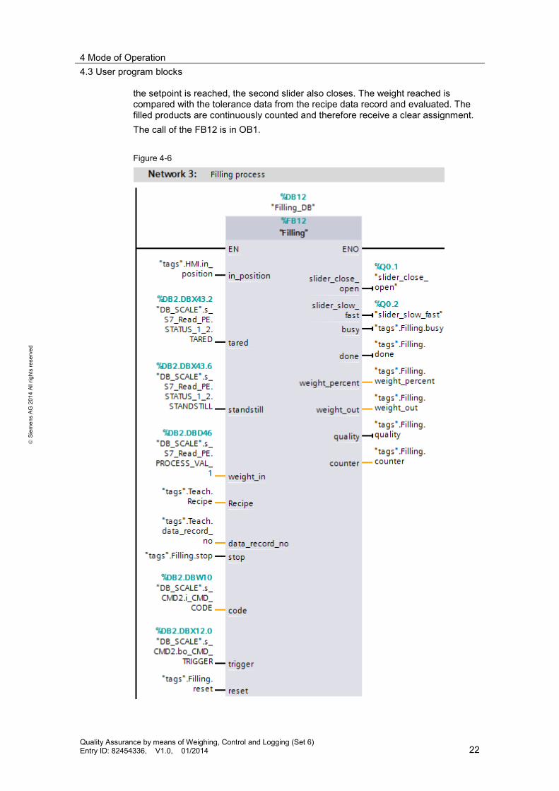
4.3.2 “Filling” function block
The FB “Filling” is used for filling a container with a selected dowel type. For this purpose, the scale is tared to neutralize the weight of the container. The recipe data record of the dowel type to be filled is loaded. The product, made up of pieces and individual weight of a dowel, results in the weight setpoint. The FB “Filling” starts the filling process by opening the two sliders. When the specified weight limit is reached, one of the sliders closes, and filling is slowed down. When
4 Mode of Operation 4.3 User program blocks
Quality Assurance by means of Weighing, Control and Logging (Set 6) Entry ID: 82454336, V1.0, 01/2014 22
S
iem
ens
AG 2
014
All r
ight
s re
serv
ed
the setpoint is reached, the second slider also closes. The weight reached is compared with the tolerance data from the recipe data record and evaluated. The filled products are continuously counted and therefore receive a clear assignment. The call of the FB12 is in OB1. Figure 4-6

4 Mode of Operation 4.3 User program blocks
Quality Assurance by means of Weighing, Control and Logging (Set 6) Entry ID: 82454336, V1.0, 01/2014 23
S
iem
ens
AG 2
014
All r
ight
s re
serv
ed
Interface Table 4-7
Name Data type Description
Input in_position Bool Box is in filling position (start request) tared Bool True = the scale is tared standstill Bool True = the scale is at a standstill weight_in Real Weight transfer from DB_SCALE Recipe "UDT_RECIPE" Recipe data (see Table 4-5) data_record_no UInt Recipe data record to be produced
Out slider_close_open Bool Slider for opening the storage container slider_slow_fast Bool Slider for accelerating the filling busy Bool Block in process done Bool Processing completed (one cycle active) weight_percent Real Filling weight in % of setpoint weight_out Real Filling weight (unit depends on the
configuration in SIWATOOL V7) quality Bool Quality assessment (true = okay) counter UDInt Product counter
InOut Local control Bool Stop (false=operation, true=stop) code Int Pointer on command code 2 (DB_SCALE) trigger Bool Pointer on command code 2 (DB_SCALE) reset Bool Reset input (reset after processing)
Static resolution Real Resolution of load cell = numerical increment d (unit depends on the configuration in SIWATOOL V7)
velocity_switch Real Value for switching the filling speed (standardized share from setpoint)

4 Mode of Operation 4.3 User program blocks
Quality Assurance by means of Weighing, Control and Logging (Set 6) Entry ID: 82454336, V1.0, 01/2014 24
S
iem
ens
AG 2
014
All r
ight
s re
serv
ed
Program flow chart The FB “Filling" is programmed as sequence. The program flow chart is as follows.
Figure 4-7
10busy = 1
0
20slider_close_open = 1
slider_slow_fast = 1
yes nosetpoint = piece_weight * quantity + resolution code = 1011
trigger = 1
standstill ?
in_position = true ?
40slider_slow_fast = 0
50slider_close_open = 0weight_out = weight_in
weight_in > velocity_switch * setpoint ?
weight_in > setpoint ?
yes noquality = 0quality = 1
weight_out >= setpoint + resolution&
weight_out < setpoint+resolution + tolerance?
weight_in = 0 ?&
tared ?
60counter = counter +1
busy = 0done = 1
0
4.3.3 “HMI” function block
The FB “HMI” is used to display the transport of the box and the slider on the operator panel. The transport path of the conveyor belt is simulated via the 10Hz clock memory bit “Clock_10Hz” and increments the position of the box by “conveyor_delta”. The user starts the conveyor belt simulation via “start_M1” on the operator panel. When the setpoint is reached on the scale, “stop_1” stops the “conveyor” position value and the “in_position” output is set for the start request for FB “Filling”. Once the FB “Filling” has finished, it triggers the “start_M2” request for removal of the filled box. For the position of the box, the “Clock_10Hz” 10Hz clock memory bit is again incremented by “conveyor_delta”. When the “stop_2” end position is reached, the conveyor belt stops the conveyor belt simulation and the box jumps back to the start position. In addition, the display of the slider positions is simulated in this block. The call of the FB13 is in OB1.

4 Mode of Operation 4.3 User program blocks
Quality Assurance by means of Weighing, Control and Logging (Set 6) Entry ID: 82454336, V1.0, 01/2014 25
S
iem
ens
AG 2
014
All r
ight
s re
serv
ed
Figure 4-8
Interface
Table 4-8
Name Data type
Description
Input start_M1 Bool Start request for the supply conveyor belt start_M2 Bool Start request for the removal conveyor belt slider_close_open Bool Slider for opening the storage container slider_slow_fast Bool Slider for accelerating the filling
Out M1 Bool Control of the supply conveyor belt M2 Bool Control of the removal conveyor belt busy Bool Block in process done Bool Processing completed (one cycle active) in_position Bool Box is in filling position (start request for FB
“Filling”) conveyor Int Simulated position of the box slider_close_open_Int Int Simulated position of the slide for opening the
storage container slider_slow_fast_Int Int Simulated position of the slide to accelerate the
filling InOut Local control Bool Stop (false=operation, true=stop)
reset Bool Reset input (reset after processing)

4 Mode of Operation 4.3 User program blocks
Quality Assurance by means of Weighing, Control and Logging (Set 6) Entry ID: 82454336, V1.0, 01/2014 26
S
iem
ens
AG 2
014
All r
ight
s re
serv
ed
Name Data type
Description
Static conveyor_delta Int Horizontal distance that the box travels in 100ms (in pixel)
stop_1 Int Horizontal position of the box on the scale (in pixel)
stop_2 Int Horizontal position of the box at the end of the removal conveyor belt (in pixel)
slider_close_open_pixel Int Pixel distance between the end positions of the slider for opening the storage container
slider_slow_fast_pixel Int Pixel distance between the end positions of the slider for accelerating the filling
Program flow chart The FB “HMI" is programmed as sequence. The program flow chart is as follows.
Figure 4-9
10busy = 1M1 = 1
0
20M1 = 0
in_position = 1
conveyor = conveyor + conveyor_delta
Clock_10Hz ?
start_M1 = true ?
0
conveyor = stop_1 ?
30M2 = 1
40M2 = 0
busy = 0done = 1
conveyor = conveyor + conveyor_delta
Clock_10Hz ?
start_M2 = true ?
conveyor = stop_2 ?
4.3.4 “Tags” data block
The “tags” data block includes the tags for transmitting the function blocks and functions to the interfaces. The following table shows the tags that have been provided with deviating start values in the example project.

4 Mode of Operation 4.4 Data logging blocks
Quality Assurance by means of Weighing, Control and Logging (Set 6) Entry ID: 82454336, V1.0, 01/2014 27
S
iem
ens
AG 2
014
All r
ight
s re
serv
ed
Table 4-9
Name Data type
Starting value
Description
unit Bool false Only display of weight unit (false =g, true=kg), no conversion (SIWATOOL V7 requires a match with the weight unit)
Teach.recipe_visible Bool false Standard recipe display on the “recipe” HMI screen visible (false =invisible, true =visible)
Teach.quantity UInt 1 Number of sample (teach mode) Teach.data_record_no UInt 1 Recipe data record to be overwritten Teach.data_record_max UInt 3 Number of recipe data records (limit of HMI
selection) DataLog.Enable Bool true Enable of FB “DataLog” (false =blocked, true
=enabled) DataLog.RECORDS UDInt 1000 Number of data records in the data log DataLog.NAME String 'DataLog' Name of the data log file time.write.set_time.year UInt 1970 “Year” input box in the “time setting” HMI screen
(system time for writing) time.write.set_time.month USInt 1 “Month” input box in the “time setting” HMI
screen (system time for writing) time.write.set_time.day USInt 1 “Day” input box in the “time setting” HMI screen
(system time for writing)
4.4 Data logging blocks
To record the production data, the following blocks are used: • “copy” (FC 142) function • “DataLog” (FB 143) function block • “time” (FC 144) function
4.4.1 “Copy” function
The FC “copy” only collects all required data that is to be written into the DataLog file and transfers it to the FB „DataLog“. The call of the FC142 is in OB1.

4 Mode of Operation 4.4 Data logging blocks
Quality Assurance by means of Weighing, Control and Logging (Set 6) Entry ID: 82454336, V1.0, 01/2014 28
S
iem
ens
AG 2
014
All r
ight
s re
serv
ed
Figure 4-10
Interface Table 4-10
Name Data type Description
Input REQ Bool Copy request (enabled when REQ = true) data_record_no UInt Recipe data record number Recipe "UDT_RECIPE" Recipe data (see Table 4-5) weight Real Filled weight quality Bool Quality of filling counter UDInt Count value of filling
Out DATA "UDT_DataLog_DATA" Summary of all DataLog data
PLC data type "UDT_DataLog_DATA" The "UDT_DataLog_DATA" PLC data type includes all process data that is to be written into the data log data record.
Table 4-11
Name Data type Description
recipe_ID UInt Recipe ID (identical with the data record number) diameter USInt Dowel diameter in mm piece_weight Real Individual weight (unit depends on the configuration in SIWATOOL V7) quantity UInt pieces tolerance Real Tolerance (unit depends on the configuration in SIWATOOL V7) weight Real Filled weight quality Bool Quality of filling packet_no UDInt Packet number (identical with count value of the filling)

4 Mode of Operation 4.4 Data logging blocks
Quality Assurance by means of Weighing, Control and Logging (Set 6) Entry ID: 82454336, V1.0, 01/2014 29
S
iem
ens
AG 2
014
All r
ight
s re
serv
ed
4.4.2 “DataLog” function block
The FB “DataLog" creates, opens and describes a DataLog file according to specifications. When exceeding the maximum entry numbers, the oldest entries are overwritten (ring buffer). The call of the FB143 is in OB1. Figure 4-11
Interface Table 4-12
Name Data type
Description
Input RECORDS UDInt Number of data records in the data log Timestamp Bool Time stamp:
• 0: No time stamp • 1: Date and time
NAME String Name of the data log Mode Bool Mode for opening the data log:
• MODE= "0" The data records of the data log are retained
• MODE= "1" The data records of the data log are deleted

4 Mode of Operation 4.4 Data logging blocks
Quality Assurance by means of Weighing, Control and Logging (Set 6) Entry ID: 82454336, V1.0, 01/2014 30
S
iem
ens
AG 2
014
All r
ight
s re
serv
ed
Name Data type
Description
Write Bool Execution of the “DataLogWrite” instruction in the event of a rising edge
HEADER String Header of the CSV file Reset Bool Input for the reset
Output State USInt Status of the function (identical with the step) ErrorStatus Word Status parameter if an error occurs (in combination with
“State”, the corresponding SFB data log can be identified) NumberRecords UDInt Current number of written data records
InOut DATA Variant Pointer to the structure or array of the data to be written
Program flow chart The FB “DataLog" is programmed as sequence. When the block is enabled (“EN”), the sequence starts step 0. A DataLog file is created in csv format in the load memory of the CPU with the specifications “NAME”, “RECORDS”, “Timestamp”, “HEADER” and “DATA”. Once the positive “DONE” feedback appears or the message that the file already exists, the file with the “MODE” mode is opened in step 1. If a message appears that the file does not exist, the block returns to step 0. If the feedback is positive, “DONE”, the file is written in step 20, when the “Write” input is enabled. If the error messages “Data log does not exist” or “Data log not open” appear, it is jumped to the respective step in order to remove the error. If there is a positive “DONE” feedback, the number of the written data records (“NumberRecords”) is incremented and the next write request (“Write”) is waited for. If another error than stated above occurs, the sequence will remain in the current step. From “State” and “ErrorStatus” the appropriate SFBs can be determined from the error description. The sequence and the counter of the written data record are reset via the “Reset” input. The program flow chart is as follows.

4 Mode of Operation 4.4 Data logging blocks
Quality Assurance by means of Weighing, Control and Logging (Set 6) Entry ID: 82454336, V1.0, 01/2014 31
S
iem
ens
AG 2
014
All r
ight
s re
serv
ed
Figure 4-12
DONE
0DataLogCreate
Status ?
10DataLogOpen
DONE
Status ?
20DataLogWrite
DONE
Status ?
INC NumberRecords
Data log already exists
Data log does not exist
Data log not openData log does not exist
4.4.3 “Time” function
The FB “HMI” is used for setting the CPU system and reading the CPU local time. The system time of the controller provides the time stamp of the DataLog data records. The CPU local time is also displayed in the HMI. The HMI system is synchronized with the CPU system time. The call of the FC144 is in OB1. Figure 4-13

4 Mode of Operation 4.4 Data logging blocks
Quality Assurance by means of Weighing, Control and Logging (Set 6) Entry ID: 82454336, V1.0, 01/2014 32
S
iem
ens
AG 2
014
All r
ight
s re
serv
ed
Interface Table 4-13
Name Data type
Description
Input set_time Struct System time for writing (input field in HMI) • year UInt Year
• month USInt Month
• day USInt Day
• hour USInt Hour
• minute USInt Minute Out write_RET_VAL Int Status of the “WR_SYS_T” instruction
read_localtime DTL Local time (is continuously read) read_RET_VAL Int Status of the “RD_LOC_T” instruction
InOut write Bool Request to write system time (reset after processing) write_systemtime DTL System time for writing in DTL format
5 Configuration and Settings 5.1 Configuring SIMATIC Panel TP700 Comfort
Quality Assurance by means of Weighing, Control and Logging (Set 6) Entry ID: 82454336, V1.0, 01/2014 33
S
iem
ens
AG 2
014
All r
ight
s re
serv
ed
5 Configuration and Settings
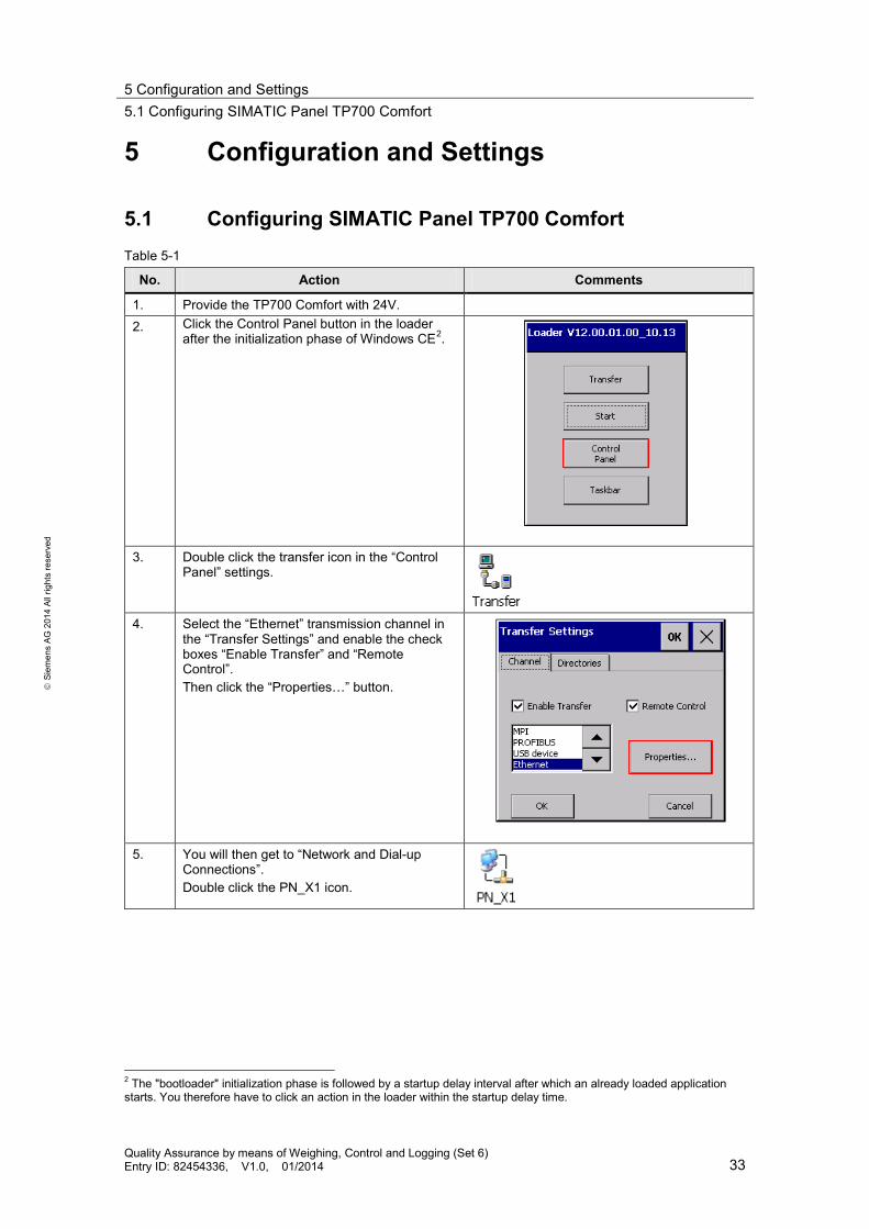
5.1 Configuring SIMATIC Panel TP700 Comfort Table 5-1
No. Action Comments
1. Provide the TP700 Comfort with 24V. 2. Click the Control Panel button in the loader
after the initialization phase of Windows CE2.
3. Double click the transfer icon in the “Control
Panel” settings.
4. Select the “Ethernet” transmission channel in
the “Transfer Settings” and enable the check boxes “Enable Transfer” and “Remote Control”. Then click the “Properties…” button.
5. You will then get to “Network and Dial-up
Connections”. Double click the PN_X1 icon.
2 The "bootloader" initialization phase is followed by a startup delay interval after which an already loaded application starts. You therefore have to click an action in the loader within the startup delay time.

5 Configuration and Settings 5.2 Network connections
Quality Assurance by means of Weighing, Control and Logging (Set 6) Entry ID: 82454336, V1.0, 01/2014 34
S
iem
ens
AG 2
014
All r
ight
s re
serv
ed
No. Action Comments
6. Enable the “Specify an IP address” checkbox and accept the displayed settings: • IP-Address: 192.168.0.2 • Subnet mask: 255.255.255.0 Finally, accept the settings made in the “PN_X1” and transfer settings with “OK”.
7. The transfer mode in the loader has to be
enabled to subsequently transfer the HMI project part into the Comfort Panel.
5.2 Network connections The LAN network card of the programming device requires a static IP address to configure the controller and the HMI and to configure the weighing module. Configuration of the LAN connection is described in the following.
Table 5-2
No. Action Comments
1. Open the network connections via Start > Control Panel> Network and Sharing > Change adapter settings”. • Select your network connection. • Open the properties via right click.
5 Configuration and Settings 5.2 Network connections
Quality Assurance by means of Weighing, Control and Logging (Set 6) Entry ID: 82454336, V1.0, 01/2014 35
S
iem
ens
AG 2
014
All r
ight
s re
serv
ed
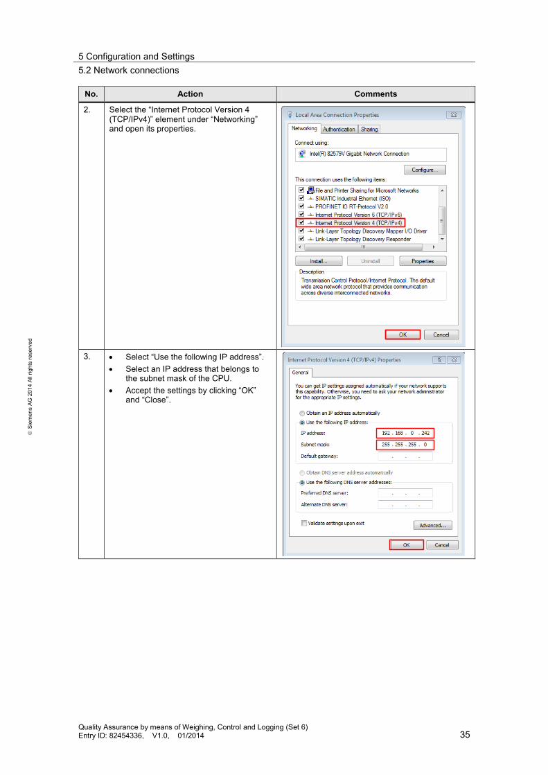
No. Action Comments
2. Select the “Internet Protocol Version 4 (TCP/IPv4)” element under “Networking” and open its properties.
3. • Select “Use the following IP address”.
• Select an IP address that belongs to the subnet mask of the CPU.
• Accept the settings by clicking “OK” and “Close”.
5 Configuration and Settings 5.3 Regional and language options
Quality Assurance by means of Weighing, Control and Logging (Set 6) Entry ID: 82454336, V1.0, 01/2014 36
S
iem
ens
AG 2
014
All r
ight
s re
serv
ed
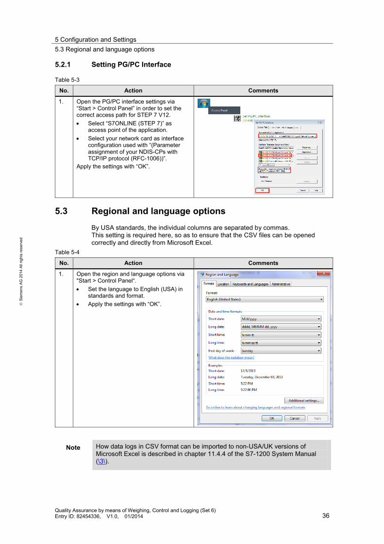
5.2.1 Setting PG/PC Interface
Table 5-3
No. Action Comments
1. Open the PG/PC interface settings via “Start > Control Panel” in order to set the correct access path for STEP 7 V12. • Select “S7ONLINE (STEP 7)” as
access point of the application. • Select your network card as interface
configuration used with “(Parameter assignment of your NDIS-CPs with TCP/IP protocol (RFC-1006))”.
Apply the settings with “OK”.
5.3 Regional and language options By USA standards, the individual columns are separated by commas. This setting is required here, so as to ensure that the CSV files can be opened correctly and directly from Microsoft Excel.
Table 5-4
No. Action Comments
1. Open the region and language options via "Start > Control Panel“. • Set the language to English (USA) in
standards and format. • Apply the settings with “OK”.
Note How data logs in CSV format can be imported to non-USA/UK versions of Microsoft Excel is described in chapter 11.4.4 of the S7-1200 System Manual (\3\).
5 Configuration and Settings 5.4 Configuring SIWAREX WP231 weighing module
Quality Assurance by means of Weighing, Control and Logging (Set 6) Entry ID: 82454336, V1.0, 01/2014 37
S
iem
ens
AG 2
014
All r
ight
s re
serv
ed
5.4 Configuring SIWAREX WP231 weighing module
Note Regarding the configuration of the SIWAREX WP231 weighing module, only the settings required for this set are displayed via the SIWATOOL V7. If other configuration changes are to be performed, use the brief instruction for the basic commissioning of a SIWAREX WP231 (\7\).
The SIWAREX WP231 has to be configured accordingly to adjust the weighing module to the load cell used and the specific application case. New modules are delivered with “factory settings”, which meet the majority of the applications. Using a command, these factory settings can also be restored later. The following configuration steps have to be made to adapt to the application: 1. Reset to factory settings 2. Specify calibration and load cell parameters
The individual elements are: – Weight unit
The weight unit (e.g. ’g’ or ’kg’) for interpreting the weight display. It determines the unit of other parameters, such as maximum weighing range, numerical increment and calibration weight 1.
– Maximum weighing range The maximum weighing range corresponds to the rated load Emax of the load cell. For the load cell used this is Emax = 3 kg.
– Resolution of the load cell The resolution corresponds to the minimum scale interval Vmin of the load cell. For the SIWAREX WL260 SP-S AA load cell used, this is Vmin = Emax/15000. This corresponds to a numerical increment d of 0.2 g.
– Calibration weight 1 ”Calibration weight”, added to the scale during calibration. The calibration weight must be at least 5% of the rated load of all connected load cells. As a calibration weight you use an object, whose exact weight you know.
– Characteristic value The characteristic value depends on the connected load cell. A characteristic value of 1.855 mV/V must be configured for the 3 kg load cell used.
The application requires the following values which deviate from the factory settings:
Table 5-5: Values deviating from the factory settings
Parameter Default Application
Weighing unit ’ kg ’ ’ g ’ Maximum weighing range 100 [ 100kg] 3000 [ 3000g] Numerical increment d 0.1 [ 0.1kg] 0.2 [ 0.2g]
5 Configuration and Settings 5.4 Configuring SIWAREX WP231 weighing module
Quality Assurance by means of Weighing, Control and Logging (Set 6) Entry ID: 82454336, V1.0, 01/2014 38
S
iem
ens
AG 2
014
All r
ight
s re
serv
ed
Parameter Default Application
Calibration weight 1 100 [ 100kg] 1100 [ 1100g] Known calibration weight which is available to the user
Number of load cells 3 1 Number of support points 3 1 Characteristic value range (mV/V)
2.0 1.855
Configuration tool
The weighing module is configured with the help of the SIWATOOL V7 (Table 2-3) configuration package.
In this example the SIWAREX WP231 weighing module is used with the firmware V1.0.3 (\5\).
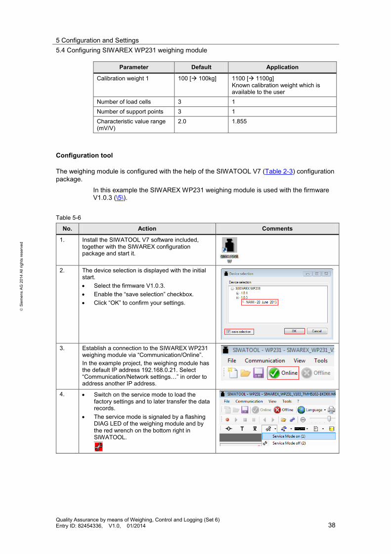
Table 5-6
No. Action Comments
1. Install the SIWATOOL V7 software included, together with the SIWAREX configuration package and start it.
2. The device selection is displayed with the initial
start. • Select the firmware V1.0.3. • Enable the “save selection” checkbox. • Click “OK” to confirm your settings.
3. Establish a connection to the SIWAREX WP231
weighing module via “Communication/Online”. In the example project, the weighing module has the default IP address 192.168.0.21. Select “Communication/Network settings…” in order to address another IP address.
4. • Switch on the service mode to load the factory settings and to later transfer the data records.
• The service mode is signaled by a flashing DIAG LED of the weighing module and by the red wrench on the bottom right in SIWATOOL.

5 Configuration and Settings 5.4 Configuring SIWAREX WP231 weighing module
Quality Assurance by means of Weighing, Control and Logging (Set 6) Entry ID: 82454336, V1.0, 01/2014 39
S
iem
ens
AG 2
014
All r
ight
s re
serv
ed
No. Action Comments
5. • Load the factory settings.
6. • Read all data from the SIWAREX WP231
weighing module via “Communication/Receive all data”.
• Confirm the subsequent question “Are you sure, all data records will be read from module to pc?” with “Yes”.
7. • Once all data is received, enter the following
parameters to data record 3: – Weighing unit: g (gram) – Maximum weighing range: 3000 g (rated
load Emax of the load cell = 3 kg) – Numerical increment d: 0.2 g (Minimum
scale interval Vmin = Emax/15000) – Calibration weight 1: Minimum 5% of rated
load Emax • The technical data of the load cell can be
found in the operating instruction for the SIWAREX WL200 (\4\) load cells.
8. • Enter the following parameters to data
record 10: – Number of load cells: 1 – Number of support points: 1 – Characteristic value (mV/V): 1.855 – Rated load of a load cell: 3000 g (Emax)
• The characteristic value C of the load cell can be found on the sticker on the load cell.

5 Configuration and Settings 5.4 Configuring SIWAREX WP231 weighing module
Quality Assurance by means of Weighing, Control and Logging (Set 6) Entry ID: 82454336, V1.0, 01/2014 40
S
iem
ens
AG 2
014
All r
ight
s re
serv
ed
No. Action Comments
9. • Write all data records from the SIWAREX WP231 weighing module via “Communication/Send all data”.
• Confirm the subsequent question “Are you sure, all data records will be sent from pc to module?” with “Yes”.
10. • Confirm the validity of the calibration point 0
for the empty scale (60) in order to calibrate it.
• Subsequently put the calibration weight onto the scale and confirm the validity of the calibration point 1 (61).
• The scale is now calibrated.
11. • Finally switch off the service mode after the
transfer of the data records.
12. • Save the settings made for other
commissioning (e.g. when replacing the load cell).
13. • Close the SIWATOOL V7.
6 Installation and Commissioning 6.1 Hardware installation
Quality Assurance by means of Weighing, Control and Logging (Set 6) Entry ID: 82454336, V1.0, 01/2014 41
S
iem
ens
AG 2
014
All r
ight
s re
serv
ed
6 Installation and Commissioning This chapter deals with the steps required to put the example into operation with the code from the download and the hardware list.
6.1 Hardware installation
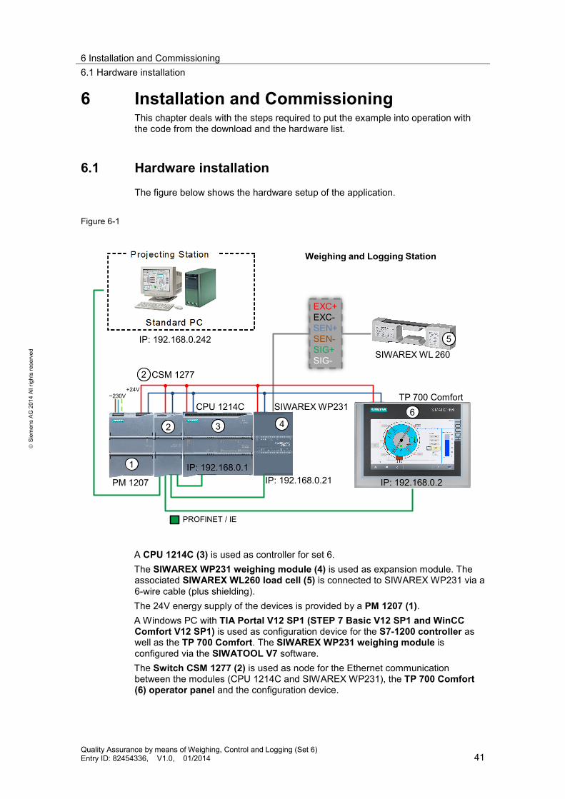
The figure below shows the hardware setup of the application.
Figure 6-1
5
6
PROFINET / IE
PM 1207
CPU 1214C
CSM 1277
SIWAREX WP231TP 700 Comfort
EXC+EXC-SEN+SEN-SIG+SIG- SIWAREX WL 260
Weighing and Logging Station
1
2 3 4
2
~230V+24V
IP: 192.168.0.242
IP: 192.168.0.2IP: 192.168.0.1
IP: 192.168.0.21
A CPU 1214C (3) is used as controller for set 6. The SIWAREX WP231 weighing module (4) is used as expansion module. The associated SIWAREX WL260 load cell (5) is connected to SIWAREX WP231 via a 6-wire cable (plus shielding). The 24V energy supply of the devices is provided by a PM 1207 (1). A Windows PC with TIA Portal V12 SP1 (STEP 7 Basic V12 SP1 and WinCC Comfort V12 SP1) is used as configuration device for the S7-1200 controller as well as the TP 700 Comfort. The SIWAREX WP231 weighing module is configured via the SIWATOOL V7 software. The Switch CSM 1277 (2) is used as node for the Ethernet communication between the modules (CPU 1214C and SIWAREX WP231), the TP 700 Comfort (6) operator panel and the configuration device.

6 Installation and Commissioning 6.2 Installation of the software (download)
Quality Assurance by means of Weighing, Control and Logging (Set 6) Entry ID: 82454336, V1.0, 01/2014 42
S
iem
ens
AG 2
014
All r
ight
s re
serv
ed
Table 6-1
No. Action Comments
1. Mount the PM1207 power module, the CPU 1214C and the SIWAREX WP231 weighing module onto the hat rail and establish the bus connection to the CPU with the slider switch of the weighing module. Do not yet supply the PM1207 power module with the power supply (230V~).
see Figure 6-1
2. Connect the CSM1277 switch, the CPU 1214C, the SIWAREX WP231 weighing module and the TP700 Comfort panel with 24V DC supply voltage of the PM1207 power module.
see Figure 6-1
3. A base and top plate has to be attached to the SIWAREX WL260 SP-S AA load cell. The drawing in the “Note” column is to be used for base plate and top plate. M6 x 15mm with washers are required as screws.
4. Connect the SIWAREX WL260 SP-S AA load
cell to the SIWAREX WP231 weighing module. see Figure 6-1
5. Connect the CPU, the weighing module, the Comfort Panel and the programming device with the help of the RJ45 cable to the CSM1277 switch.
see Figure 6-1
6. Connect all ground connections to earth. 7. Provide the PM1207 power module with the
power supply (230V~).
6.2 Installation of the software (download)
This chapter describes the steps for the installation of the example code.
Note At this point, it is assumed that the necessary software has been installed on your computer and that you are familiar with handling the software.
Kopfplatte
Grundplatte
W ä
Top plate
Base plate
Weighing module
Threaded bores Thread Designation Thread depth

6 Installation and Commissioning 6.3 Downloading the Startup Code
Quality Assurance by means of Weighing, Control and Logging (Set 6) Entry ID: 82454336, V1.0, 01/2014 43
S
iem
ens
AG 2
014
All r
ight
s re
serv
ed
Preliminary Remarks
For the startup, we offer you software examples with test code and test parameters as a download. The software examples support you during the first steps and tests with the set 6. They enable a quick test of hardware and software interfaces between the products described in the set.
The software examples are always assigned to the components used in the set and show their basic interaction. However, they are not real applications in the sense of technological problem solving with definable properties.
6.3 Downloading the Startup Code The software examples are available on the HTML page from which you downloaded this document.
Loading configuration of the weighing module
Table 6-2
No. Action Comments
1. Open the “SIWAREX_WP231_V103_7MH5102-1KD00.WP231” configuration file for the SIWAREX WL 260 SP-S AA 3kg C3 load cell with SIWATOOL V7.
2. Establish a connection to the SIWAREX WP231 weighing module via “Communication/Online”. In the example project, the weighing module has the default IP address 192.168.0.21. Select “Communication/Network settings…” in order to address another IP address.
3. • Switch on the service mode to load the factory settings and to transfer the data records.
• The service mode is signaled by a flashing DIAG LED of the weighing module and by the red wrench on the bottom right in SIWATOOL.
4. • Load the factory settings.

6 Installation and Commissioning 6.3 Downloading the Startup Code
Quality Assurance by means of Weighing, Control and Logging (Set 6) Entry ID: 82454336, V1.0, 01/2014 44
S
iem
ens
AG 2
014
All r
ight
s re
serv
ed
No. Action Comments
5. • Write all data records from the SIWAREX WP231 weighing module via “Communication/Send all data”.
• Confirm the subsequent question “Are you sure, all data records will be sent from pc to module?” with “Yes”.
6. • Finally switch off the service mode after the
transfer of the data records.
7. • Close the SIWATOOL V7.
Downloading the TIA Portal project
Table 6-3
No.
Action Comments
1. Open the “82454336_S7-1200+SIWAREX_Set6_CODE_v1d0.ap12” project with the TIA Portal V12 SP1.
2. Select the “PLC_1” control project folder and
confirm the button for loading the CPU.
3. Select the project folder for the “HMI_1” operator
panel and click the button to load it into the Comfort Panel. Alternatively, you can simulate the TP700 Comfort operator panel also without hardware via the TIA Portal.
7 Operating the Application 7.1 Overview
Quality Assurance by means of Weighing, Control and Logging (Set 6) Entry ID: 82454336, V1.0, 01/2014 45
S
iem
ens
AG 2
014
All r
ight
s re
serv
ed
7 Operating the Application 7.1 Overview
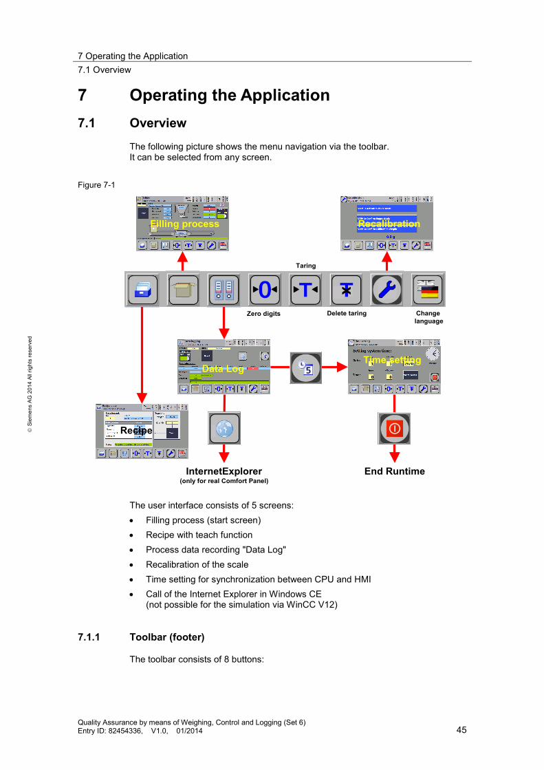
The following picture shows the menu navigation via the toolbar. It can be selected from any screen.
Figure 7-1
RecalibrationFilling process
Time settingData Log
Recipe
InternetExplorer(only for real Comfort Panel)
End Runtime
Zero digits Delete taring
Taring
Change language
The user interface consists of 5 screens: • Filling process (start screen) • Recipe with teach function • Process data recording "Data Log" • Recalibration of the scale • Time setting for synchronization between CPU and HMI • Call of the Internet Explorer in Windows CE
(not possible for the simulation via WinCC V12)
7.1.1 Toolbar (footer)
The toolbar consists of 8 buttons:

7 Operating the Application 7.1 Overview
Quality Assurance by means of Weighing, Control and Logging (Set 6) Entry ID: 82454336, V1.0, 01/2014 46
S
iem
ens
AG 2
014
All r
ight
s re
serv
ed
• Via you get to the recipe view. This is where you can execute the teach function.
• Via you get to the display of the filling process. This is also the start screen.
• Via you get to the overview of the “Data Log” process data recording.
• The scale can set to zero via . This is used when the scale is empty but does not display precisely 0 g because of soiling.
• The scale can be tared via . This is where scale is set to zero and the weight difference is saved as tare weight. This function is required to determine the net weight (content of the container).
• The taring can be deleted via . The tare value is deleted and the scale will show the gross weight again (weight of container + content).
• Via you get to the recalibration of the scale.
• You can toggle between German and English via .
7.1.2 Header with scale status
The header provides you with information on the current screen and the status of the weighing module.
Figure 7-2
3 5 6 129
12 4 7 8 10 11 1413
The header shows the following: 1. Screen name 2. Screen icon (identical with the button icon in the toolbar) 3. Local time of the controller 4. Tare: tare value display (weight of the container during taring) 5. Limit value 1 (configurable via SIWATOOL V7) 6. Limit value 2 (configurable via SIWATOOL V7) 7. Empty: The scale is in a defined empty range (configurable via SIWATOOL
V7). 8. Standstill: The weight is in a stable state.

7 Operating the Application 7.2 Commissioning
Quality Assurance by means of Weighing, Control and Logging (Set 6) Entry ID: 82454336, V1.0, 01/2014 47
S
iem
ens
AG 2
014
All r
ight
s re
serv
ed
9. ¼ d zero: The scale is +/- of a quarter numerical increment to the zero point (important for scales requiring verified calibration).
10. Max. 9e: The current weight is more than 9 numerical increments above the defined weighing range (important for scales requiring verified calibration).
11. Tared: The scale is tared. 12. Preset tare: The scale was tared via a specified tare value. 13. Service: The service mode of the scale is switched on. 14. Error: The operation of the scale is faulty.
7.2 Commissioning
The following steps have to be performed to correctly operate the application.
7.2.1 Setting time
The application includes a time synchronization between CPU and HMI. The time stamp of the controller is recorded for the process data recording via “DataLog”. This screen enables you to set the CPU system time. Depending on the CPU settings for time zone and daylight saving time, there is an offset between system and local time, which is synchronized via the HMI time in the header.
Figure 7-3
45
The following objects are important for setting the time: 1. Local time of the controller 2. Local time of the operator panel (synchronization is only possible for real HMI)

7 Operating the Application 7.2 Commissioning
Quality Assurance by means of Weighing, Control and Logging (Set 6) Entry ID: 82454336, V1.0, 01/2014 48
S
iem
ens
AG 2
014
All r
ight
s re
serv
ed
3. Input fields for setting the CPU system time (please note the possible offset between system and local time when entering; in the example project, project system and local time are identical)
4. Button for accepting the set CPU system time 5. Ending runtime (for example, to make time zone settings in Windows CE)
7.2.2 Recalibrating
The scale can be calibrated via the SIWATOOL (Table 5-6) configuration package or via this screen. For this purpose, you require the weight, you have entered as “Calibration weight 1” in data record 3 in the SIWATOOL and that you have transferred to the weighing module.
Figure 7-4
14
5
To calibrate the scale via this screen, proceed as follows:
1. Enable the service mode (signaling via “Service” status display ).
2. Confirm the empty weight of the empty scale (the weight display will then show “0.0 g”).
3. Then put the calibration weight onto the scale and confirm its validity. The weight display then shows the configured value of the “Calibration weight 1” in the SIWATOOL.
The scale is now calibrated. When exiting this screen, the service mode is disabled.

7 Operating the Application 7.3 Live demo
Quality Assurance by means of Weighing, Control and Logging (Set 6) Entry ID: 82454336, V1.0, 01/2014 49
S
iem
ens
AG 2
014
All r
ight
s re
serv
ed
7.3 Live demo
This chapter explains the procedure for production. The application-specific HMI operation consists of the screens:
• Recipe • Filling process • Data Log
7.3.1 Recipe
In this screen you can select the product to be produced, as well as determine the individual weight via the teach function.
Figure 7-5
1 2
8
5
6
7
3
4
The “recipe” screen consists of an overview field with information on the selected recipe data record (1) and an operator panel for the teaching function (2). In HMI, a “dowel” recipe has been created for this application with the following three data records: 1. Dowel 6mm x 200 2. Dowel 8mm x 100 3. Dowel 10mm x 50 Select the goods to be filled via the data record number (3). As a result, the data information (4) is read from the HMI: • Data record name • Dowel diameter • Number of dowels
7 Operating the Application 7.3 Live demo
Quality Assurance by means of Weighing, Control and Logging (Set 6) Entry ID: 82454336, V1.0, 01/2014 50
S
iem
ens
AG 2
014
All r
ight
s re
serv
ed
• Individual weight of a dowel • Weight tolerance for the quality assessment of the quantity filled
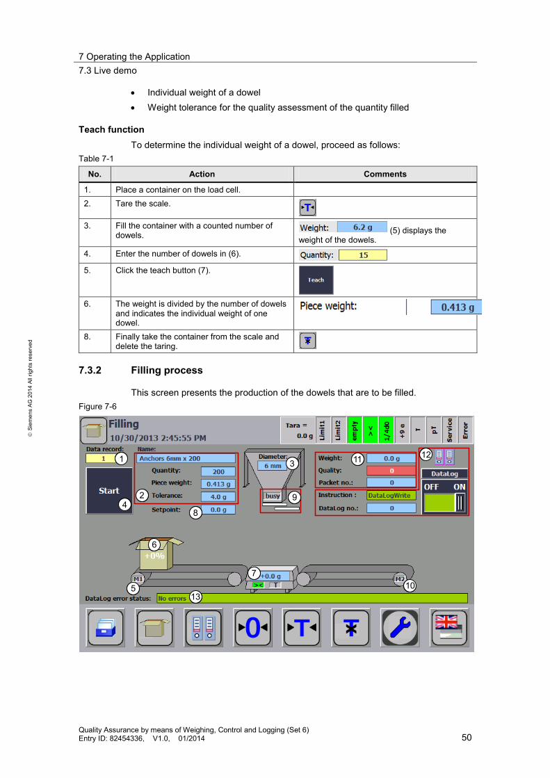
Teach function To determine the individual weight of a dowel, proceed as follows:
Table 7-1
No. Action Comments
1. Place a container on the load cell. 2. Tare the scale.
3. Fill the container with a counted number of
dowels. (5) displays the weight of the dowels.
4. Enter the number of dowels in (6). 5. Click the teach button (7).
6. The weight is divided by the number of dowels
and indicates the individual weight of one dowel.
8. Finally take the container from the scale and delete the taring.
7.3.2 Filling process
This screen presents the production of the dowels that are to be filled. Figure 7-6
1
2
3
4
5
6
7
8
9
11 12
1310

7 Operating the Application 7.3 Live demo
Quality Assurance by means of Weighing, Control and Logging (Set 6) Entry ID: 82454336, V1.0, 01/2014 51
S
iem
ens
AG 2
014
All r
ight
s re
serv
ed
Select the dowels to be filled via the data record number (1) (size and number). As a result, the field (2) will show the recipe data: • Data record name • Number of dowels • Individual weight of a dowel • Weight tolerance for the quality assessment of the quantity filled The storage container contains the dowel size depending on the selected recipe data record with the respective diameter (3). To be able to start the filling of the selected dowel recipe, proceed as follows:
Table 7-2
No. Action Comments
1. Place a container on the load cell. The scale will then display the weight of the container: (7)
2. Click the start button (4).
3. The “M1” (5) conveyor belt moves the packet
(6) onto the scale.
4. When the scale is reached, and the conditions standstill and weight recording larger than zero have been fulfilled: • the scale is tared, • the setpoint specification (8) is calculated: msetpoint = msetpoint (recipe) + mresolution (load cell) • the sliders for filling (9) are opened.
The filling process is indicated by the flashing blue arrow.
5. Fill the container with the selected dowel type.
From 90% of the setpoint weight the 2nd slider is closed and the filling speed is reduced. The slow filling speed is indicated by the flashing white arrow.
6. Continue to fill the container with the selected dowel type.
From 100% of the setpoint weight the 1st slider is also closed and filling is finished.
7. The weight reached is compared with the setpoint specifications as soon as the scale comes to a standstill. The quality is positive (true), when msetpoint <= mactual <= msetpoint + mtolerance
Outside of these limits, the quality is assessed as negative (false). The determined values are saved as new entry in the DataLog file.
8. Finally the assessed packet is removed. Remove the packet from the scale and place a new empty container on the empty scale for the next filling process.

7 Operating the Application 7.3 Live demo
Quality Assurance by means of Weighing, Control and Logging (Set 6) Entry ID: 82454336, V1.0, 01/2014 52
S
iem
ens
AG 2
014
All r
ight
s re
serv
ed
7.3.3 DataLog
This screen is used to evaluate the status of the process data recording.
Figure 7-7
45
1
23
6
87
1. Determine the maximum number of data records and the name of the DataLog
file via the input fields “RECORDS” and “NAME”. 2. The sequence of the FB “DataLog” is reset via the “Reset” button and the csv
file is created and opened according to the specifications of the input fields “RECORDS” and “NAME”. Prerequisite for this is that the FB “DataLog” is enabled (“DataLog” slider switch is set to “ON”) and that there is not yet a file with the same name.
3. The last data record of the DataLog file is displayed with the recorded process values.
4. After each filling, the determined process data is recorded and the DataLog number is incremented by one.
5. The status of the sequence specifies at which step the FB “DataLog” is located: – Step 0: DataLogCreate – Step 10: DataLogOpen – Step 20: DataLogWrite
6. If there are any possible errors, the hexadecimal error code is displayed with the respective error message.
7. Via this button you get to the web server of the S7-1200 controller (only possible for real Comfort Panel).
8. Via this button you get to the time setting of the S7-1200 controller.

7 Operating the Application 7.3 Live demo
Quality Assurance by means of Weighing, Control and Logging (Set 6) Entry ID: 82454336, V1.0, 01/2014 53
S
iem
ens
AG 2
014
All r
ight
s re
serv
ed
7.3.4 Reading out the DataLog file
You have the option to read out the csv file with the record process data via the Internet Explorer in Windows CE on your Comfort Panel or via an Internet Browser on your programming device. Proceed as follows:
Table 7-3
No. Action Comments
1 • Start the Internet Explorer. • As address, enter the IP address of
the CPU: In this case: http://192.168.0.1
• Click "ENTER".
2 You get to the start page. Here, you have
the option to log into the web server in order to have write access (e.g. to delete DataLog files). Enter the name “admin” and omit the “Password” field and subsequently click “Log in”. • Open the list of the recorded files via
the “Data Logs” menu item.

7 Operating the Application 7.3 Live demo
Quality Assurance by means of Weighing, Control and Logging (Set 6) Entry ID: 82454336, V1.0, 01/2014 54
S
iem
ens
AG 2
014
All r
ight
s re
serv
ed
No. Action Comments
4 A list with all available DataLog files opens, including date and UTC time stamp of the last access. You can specify how many entries are displayed per DataLog file via the “Files” column by specifying "Number of recent entries to view". When clicking onto DataLog file via the “Files” column, the last 25 entries are downloaded and displayed in the setting displayed. Use the “Download” column to download and display the complete DataLog file including all entries. • Click the disk icon in the “Download”
column of the “DataLog” file.
5 The “File Download” window gives you the
option to open the csv file directly with a selected program or to save it first. • Click the “Open” button.
6 Due to the previously defined default and
format settings (see chapter 5.3), the CSV file will be correctly displayed in Microsoft Excel with the columns • “Record” entry number • "Date" • “UTC Time” time stamp • “recipe_ID” recipe number • "diameter" • "piece_weight" individual weight • "quantity“ number of pieces • "tolerance" • "weight" measured weight • "quality" • "packet_no" packet number
The Comfort Panel has USB ports and offers you the option to save the csv file onto an USB stick. The csv file can also be downloaded automatically at specified times via “planned task” in the Windows operating system together with the Mozilla Firefox Internet browser (\16\).

8 Literature
Quality Assurance by means of Weighing, Control and Logging (Set 6) Entry ID: 82454336, V1.0, 01/2014 55
Cop
yrig
ht
Sie
men
s AG
201
4 Al
l rig
hts
rese
rved
8 Literature Table 8-1
Topic Title
\1\ Siemens Industry Online Support
http://support.automation.siemens.com
\2\ Download page of the entry
http://support.automation.siemens.com/WW/view/en/82454336
\3\ S7-1200 Programmable Controller System Manual
http://support.automation.siemens.com/WW/view/en/36932465
\4\ Operating instruction SIWAREX WL200 load cells
http://support.automation.siemens.com/WW/view/en/32466622
\5\ Firmware SIWAREX WP231
http://support.automation.siemens.com/WW/view/en/75231231
\6\ TIA Portal program "Ready for use" for SIWAREX WP231
http://support.automation.siemens.com/WW/view/en/66825585
\7\ Brief instruction for basic commissioning of a SIWAREX WP231
http://support.automation.siemens.com/WW/view/en/73517989
\8\ SIWAREX WP231 electronic weighing system
http://support.automation.siemens.com/WW/view/en/65621196
\9\ Service pack 1 for SIMATIC STEP 7 V12 (TIA Portal) incl. PLCSIM
http://support.automation.siemens.com/WW/view/en/75277515
\10\ Service pack 1 for SIMATIC WinCC V12 (TIA Portal)
http://support.automation.siemens.com/WW/view/en/73956248
\11\ Updates for STEP 7 V12 SP1 and WinCC V12 SP1
http://support.automation.siemens.com/WW/view/en/78683919
\12\ Operating system update for SIMATIC S7-1200 CPU Firmware V3
http://support.automation.siemens.com/WW/view/en/64789124
\13\ STEP 7 Basic V12.0 System Manual
http://support.automation.siemens.com/WW/view/en/77992779
\14\ WinCC Advanced V12.0 SP1 System Manual
http://support.automation.siemens.com/WW/view/en/78318776
\15\ SIMATIC HMI Comfort Panels operator panels
http://support.automation.siemens.com/WW/view/en/49313233
\16\ Process Data Acquisition and Monitoring with SIMATIC S7-1200 (Data Logging)
http://support.automation.siemens.com/WW/view/en/64396156

9 History
Quality Assurance by means of Weighing, Control and Logging (Set 6) Entry ID: 82454336, V1.0, 01/2014 56
Cop
yrig
ht
Sie
men
s AG
201
4 Al
l rig
hts
rese
rved
9 History Table 9-1
Version Date Modifications
V1.0 01/2014 First version