application of computational fluid dynamics to practical ... · application of computational fluid...
TRANSCRIPT
10
Application of Computational Fluid Dynamics to Practical Design and Performance Analysis
of Turbomachinery
Hyoung Woo OH Chungju National University
Korea
1. Introduction
Over the past several decades, the meanline analysis method based on the conventional empirical loss correlations, assuming that the flow characteristics averaged over the cross-section of flow passage could represent the three-dimensional flow phenomena through the passage of turbomachinery, has been widely employed to determine the overall geometric design variables for each component of turbomachinery and to predict the on and off-design performance characteristics. With the relentless increase in computing power, however, the computational fluid dynamics (CFD) techniques have remarkably progressed in the last decade, and CFD becomes commonly used not only as a design tool to improve the flow dynamic performance of specific components of turbomachinery but also as a virtual test rig to numerically experiment on a working prototype of the new/existing model. This Chapter demonstrates how the meanline and CFD analyses can be applied to carrying out the hydraulic design optimization and performance analysis of a mixed-flow pump with the non-dimensional specific-speed (Ns) of 2.44. Although the present article focuses on the incompressible flow machine, which falls into the regime of mixed-flow pumps with the non-dimensional specific-speed in the range of 1.9 to 2.5, the following procedure presented herein can be used efficiently as a practical design and analysis guide for general purpose turbomachinery.
2. Experimental apparatus for hydraulic performance
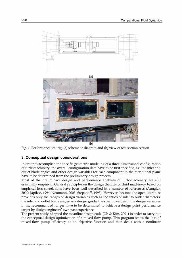
The Maritime and Ocean Engineering Research Institute (MOERI) constructed an apparatus (Fig. 1) to simulate the performance characteristics of the mixed-flow pump and conducted experiments on the hydraulic performance for the head rise, input power, pump efficiency versus flowrate, and the cavitation characteristics. The pump flowrate is calculated from the pressure difference across a downstream nozzle. Wall static pressures at the inlet and outlet planes are averaged in a manifold with four duct taps. The bulk total pressure, delivered head, is derived from the wall static pressure measurements and from the assumption of uniform velocity at the inflow and outflow stations. The input power is obtained from the torque transducer and impeller rotational speed readings. Uncertainties are ±1% for head, flowrate, and shaft torque and ±1 r/min for shaft speed.
Source: Computational Fluid Dynamics, Book edited by: Hyoung Woo OH, ISBN 978-953-7619-59-6, pp. 420, January 2010, INTECH, Croatia, downloaded from SCIYO.COM
www.intechopen.com
Computational Fluid Dynamics
228
(a)
(b)
Fig. 1. Performance test rig: (a) schematic diagram and (b) view of test section section
3. Conceptual design considerations
In order to accomplish the specific geometric modeling of a three-dimensional configuration of turbomachinery, the overall configuration data have to be first specified, i.e. the inlet and outlet blade angles and other design variables for each component in the meridional plane have to be determined from the preliminary design process. Most of the preliminary design and performance analyses of turbomachinery are still essentially empirical. General principles on the design theories of fluid machinery based on empirical loss correlations have been well described in a number of references (Aungier, 2000; Japikse, 1994; Neumann, 2005; Stepanoff, 1993). However, because the open literature provides only the ranges of design variables such as the ratios of inlet to outlet diameters, the inlet and outlet blade angles as a design guide, the specific values of the design variables in the recommended ranges have to be determined to achieve a design point performance target by design engineers’ own past experience. The present study adopted the meanline design code (Oh & Kim, 2001) in order to carry out the conceptual design optimization of a mixed-flow pump. This program states the loss of mixed-flow pump efficiency as an objective function and then deals with a nonlinear
www.intechopen.com
Application of Computational Fluid Dynamics to Practical Design and Performance Analysis of Turbomachinery
229
1h
D1t
Dimpθ
1δ
δ2
z,impL
D2h
D2t
z,diff
δD3t
D3h
3
L
4δ
D4hθ
diff
cD
4tD
Fig. 2. Meridional cross-section of mixed-flow pump with geometric parameters
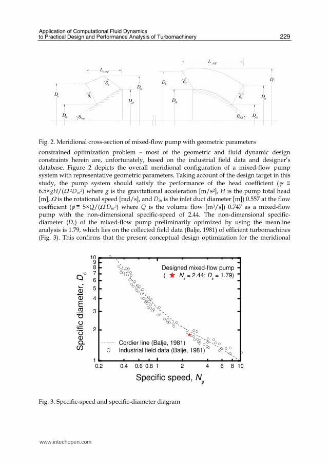
constrained optimization problem – most of the geometric and fluid dynamic design constraints herein are, unfortunately, based on the industrial field data and designer’s database. Figure 2 depicts the overall meridional configuration of a mixed-flow pump system with representative geometric parameters. Taking account of the design target in this
study, the pump system should satisfy the performance of the head coefficient (ψ ≡
6.5×gH/(Ω 2Din2) where g is the gravitational acceleration [m/s2], H is the pump total head
[m], Ω is the rotational speed [rad/s], and Din is the inlet duct diameter [m]) 0.557 at the flow
coefficient (φ ≡ 5×Q/(Ω Din3) where Q is the volume flow [m3/s]) 0.747 as a mixed-flow pump with the non-dimensional specific-speed of 2.44. The non-dimensional specific-diameter (Ds) of the mixed-flow pump preliminarily optimized by using the meanline analysis is 1.79, which lies on the collected field data (Balje, 1981) of efficient turbomachines (Fig. 3). This confirms that the present conceptual design optimization for the meridional
0.2 0.4 0.6 0.8 1 2 4 6 8 101
2
3
4
5
6
789
10
Cordier line (Balje, 1981)
Industrial field data (Balje, 1981)
Specific
dia
mete
r, D
s
Specific speed, Ns
Designed mixed-flow pump
( Ns = 2.44; D
s = 1.79)
Fig. 3. Specific-speed and specific-diameter diagram
www.intechopen.com
Computational Fluid Dynamics
230
configuration has been accomplished within the reliable design regime. As a reference, the Cordier line (Balje, 1981), which is a fair curve through the field data in the statistical sense, is represented in Fig. 3.
4. Detailed design optimization and performance analysis using CFD
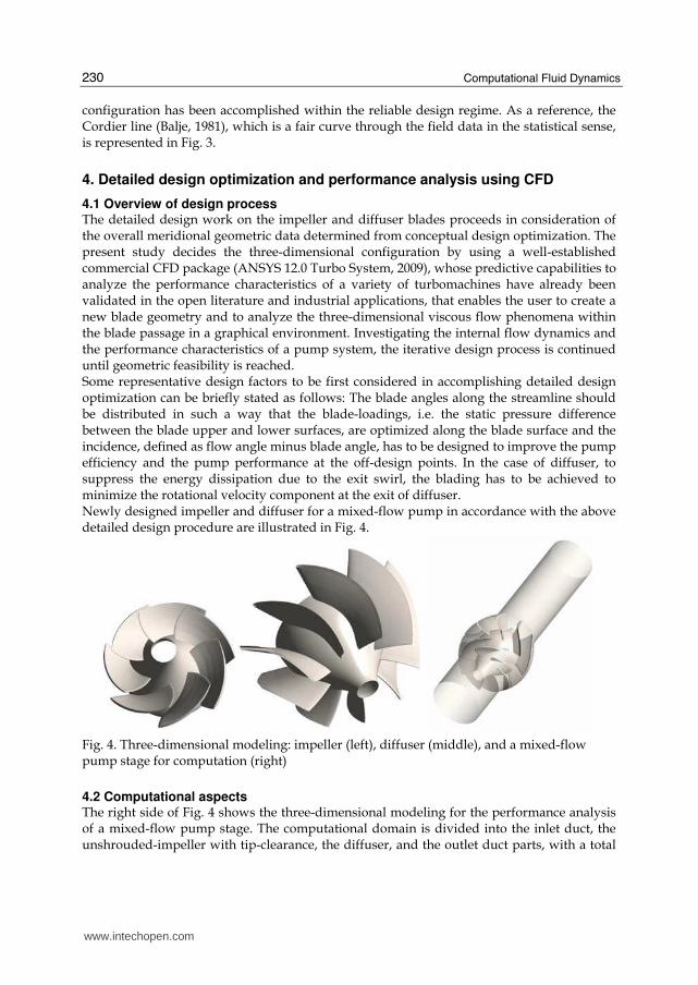
4.1 Overview of design process The detailed design work on the impeller and diffuser blades proceeds in consideration of the overall meridional geometric data determined from conceptual design optimization. The present study decides the three-dimensional configuration by using a well-established commercial CFD package (ANSYS 12.0 Turbo System, 2009), whose predictive capabilities to analyze the performance characteristics of a variety of turbomachines have already been validated in the open literature and industrial applications, that enables the user to create a new blade geometry and to analyze the three-dimensional viscous flow phenomena within the blade passage in a graphical environment. Investigating the internal flow dynamics and the performance characteristics of a pump system, the iterative design process is continued until geometric feasibility is reached. Some representative design factors to be first considered in accomplishing detailed design optimization can be briefly stated as follows: The blade angles along the streamline should be distributed in such a way that the blade-loadings, i.e. the static pressure difference between the blade upper and lower surfaces, are optimized along the blade surface and the incidence, defined as flow angle minus blade angle, has to be designed to improve the pump efficiency and the pump performance at the off-design points. In the case of diffuser, to suppress the energy dissipation due to the exit swirl, the blading has to be achieved to minimize the rotational velocity component at the exit of diffuser. Newly designed impeller and diffuser for a mixed-flow pump in accordance with the above detailed design procedure are illustrated in Fig. 4.
Fig. 4. Three-dimensional modeling: impeller (left), diffuser (middle), and a mixed-flow pump stage for computation (right)
4.2 Computational aspects The right side of Fig. 4 shows the three-dimensional modeling for the performance analysis of a mixed-flow pump stage. The computational domain is divided into the inlet duct, the unshrouded-impeller with tip-clearance, the diffuser, and the outlet duct parts, with a total
www.intechopen.com
Application of Computational Fluid Dynamics to Practical Design and Performance Analysis of Turbomachinery
231
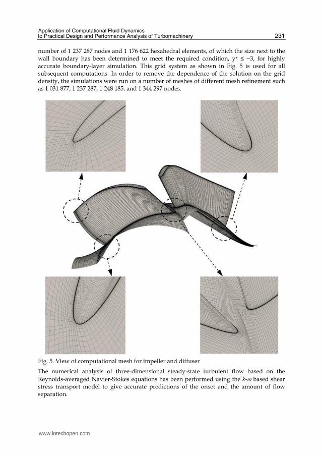
number of 1 237 287 nodes and 1 176 622 hexahedral elements, of which the size next to the wall boundary has been determined to meet the required condition, y+ ≤ ~3, for highly accurate boundary-layer simulation. This grid system as shown in Fig. 5 is used for all subsequent computations. In order to remove the dependence of the solution on the grid density, the simulations were run on a number of meshes of different mesh refinement such as 1 031 877, 1 237 287, 1 248 185, and 1 344 297 nodes.
Fig. 5. View of computational mesh for impeller and diffuser
The numerical analysis of three-dimensional steady-state turbulent flow based on the
Reynolds-averaged Navier-Stokes equations has been performed using the k-ω based shear stress transport model to give accurate predictions of the onset and the amount of flow separation.
www.intechopen.com
Computational Fluid Dynamics
232
As for the boundary conditions, the total pressure was prescribed at the inflow boundary, whereas the mass flowrate was specified at the outlet section of the pump stage. The inlet duct, diffuser, and outlet duct were set as absolute stationary. The surfaces of the unshrouded-impeller blade and hub were the relative stationary except for the impeller shroud casing wall, which was modeled as stationary in the absolute frame of reference. All computations have been carried out using water at 25 ˚C as a working fluid. A multiple frame of reference calculation with a general grid interface, which permits non-matching of node location, element type, surface extent, surface shape, and flow physics across the connection, solves a series of both rotating and stationary components, and the flow passing through the frame-change interface called a stage or mixing-plane interface is calculated by averaging the flux in the circumferential direction, although the variation in the meridional plane is preserved. Moreover, the rotationally periodic boundary conditions for each component with one blade passage are implemented in order to reduce the computational mesh size of the mixed-flow pump stage.
4.3 Internal flow characteristics at design flow and off-design performance curves A computational study has been carried out to determine the performance characteristics of
a mixed-flow pump under the normal operating conditions. Figures 6 to 8 show the
representative flow dynamic phenomena for the design flowrate in a mixed-flow pump
developed by the present design and analysis method. Here, the notation ‘ii’ means the
interface between the inlet duct and the impeller, and ‘id’ does the interface between the
impeller and the diffuser. In addition, ‘do’ denotes the interface between the diffuser and
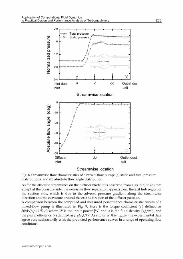
the outlet duct. Figure 6(a) illustrates the computed streamwise static and total pressure
(normalized by the atmospheric pressure) distributions through the flow passage in the
pump stage. The overall performance curves gradually increase and then level out.
Observing the static pressure distribution in the diffuser part, the static pressure rises as the
flow diffuses because of the expansion of flow area, and the local flow acceleration caused
by the curvature near the hub region of the diffuser exit leads to a slight fall in the static
pressure distribution.
In order to decrease the total pressure loss, i.e. the energy dissipation due to the exit swirls
of a pump stage, or to improve the pump efficiency, the rotational (or tangential)
component of the absolute velocity through the diffuser and outlet duct passages has to be
minimized. As can be seen in Fig. 6(b), the calculated absolute flow angle (measured from
the meridional plane) remains satisfactorily constant at around -2.1˚, which represents that
the diffuser blading has been obtained to eliminate the swirling flow in the outlet of the
pump stage.
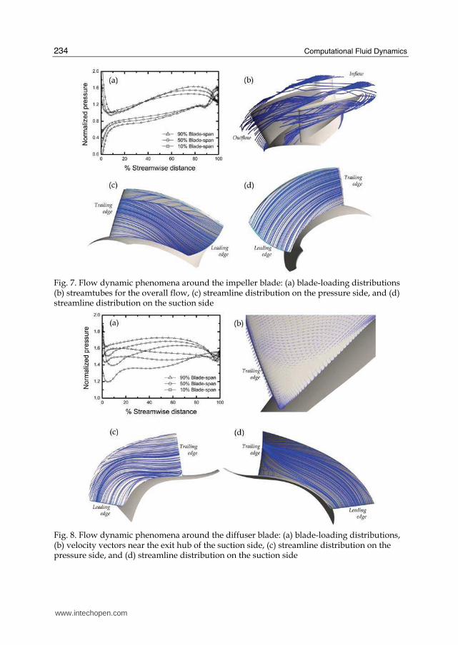
Figures 7(a) and 8(a) show that the blade-loadings for the static pressure (normalized by the
atmospheric pressure) are ideally distributed along the streamlines of the impeller and the
diffuser over the blade-span, although the flow reversal phenomena appear near the exit
regions, which is substantially regarded as the flow separation. In Figs. 7(b) to (d), the
relative flow streamlines on the impeller blade surfaces have been well optimized without
any separation lines. However, the elliptic configuration for the impeller trailing edge and
the centrifugal force induced by the impeller rotation give rise to the flow separation along
the trailing edge, and the secondary flows due to vortex-curling over the impeller blade tip
affect the flow separation on the pressure surface of impeller near around 75% blade-span.
www.intechopen.com
Application of Computational Fluid Dynamics to Practical Design and Performance Analysis of Turbomachinery
233
Fig. 6. Streamwise flow characteristics of a mixed-flow pump: (a) static and total pressure distributions, and (b) absolute flow angle distribution
As for the absolute streamlines on the diffuser blade, it is observed from Figs. 8(b) to (d) that except at the pressure side, the excessive flow separation appears near the exit hub region of the suction side, which is due to the adverse pressure gradient along the streamwise direction and the curvature around the exit hub region of the diffuser passage. A comparison between the computed and measured performance characteristic curves of a
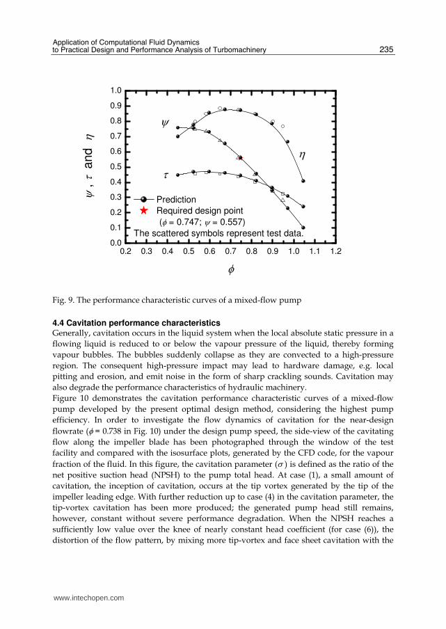
mixed-flow pump is illustrated in Fig. 9. Here is the torque coefficient (τ ) defined as
30×Ẃ/(ρ Ω 3Din5) where Ẃ is the input power [W] and ρ is the fluid density [kg/m3], and
the pump efficiency (η) defined as ρ gHQ/Ẃ. As shown in this figure, the experimental data agree very satisfactorily with the predicted performance curves in a range of operating flow conditions.
www.intechopen.com
Computational Fluid Dynamics
234
Fig. 7. Flow dynamic phenomena around the impeller blade: (a) blade-loading distributions (b) streamtubes for the overall flow, (c) streamline distribution on the pressure side, and (d) streamline distribution on the suction side
Fig. 8. Flow dynamic phenomena around the diffuser blade: (a) blade-loading distributions, (b) velocity vectors near the exit hub of the suction side, (c) streamline distribution on the pressure side, and (d) streamline distribution on the suction side
www.intechopen.com
Application of Computational Fluid Dynamics to Practical Design and Performance Analysis of Turbomachinery
235
0.2 0.3 0.4 0.5 0.6 0.7 0.8 0.9 1.0 1.1 1.20.0
0.1
0.2
0.3
0.4
0.5
0.6
0.7
0.8
0.9
1.0
ητ
ψ
Prediction
Required design point
(φ = 0.747; ψ = 0.557)
The scattered symbols represent test data.
ψ , τ a
nd
η
φ
Fig. 9. The performance characteristic curves of a mixed-flow pump
4.4 Cavitation performance characteristics Generally, cavitation occurs in the liquid system when the local absolute static pressure in a
flowing liquid is reduced to or below the vapour pressure of the liquid, thereby forming
vapour bubbles. The bubbles suddenly collapse as they are convected to a high-pressure
region. The consequent high-pressure impact may lead to hardware damage, e.g. local
pitting and erosion, and emit noise in the form of sharp crackling sounds. Cavitation may
also degrade the performance characteristics of hydraulic machinery.
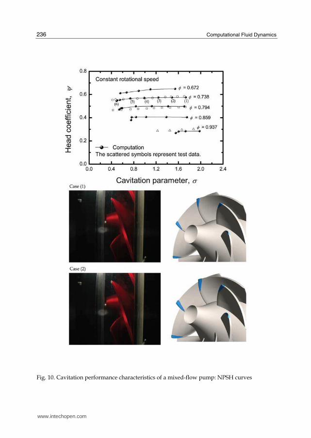
Figure 10 demonstrates the cavitation performance characteristic curves of a mixed-flow
pump developed by the present optimal design method, considering the highest pump
efficiency. In order to investigate the flow dynamics of cavitation for the near-design
flowrate (φ = 0.738 in Fig. 10) under the design pump speed, the side-view of the cavitating
flow along the impeller blade has been photographed through the window of the test
facility and compared with the isosurface plots, generated by the CFD code, for the vapour
fraction of the fluid. In this figure, the cavitation parameter (σ ) is defined as the ratio of the
net positive suction head (NPSH) to the pump total head. At case (1), a small amount of
cavitation, the inception of cavitation, occurs at the tip vortex generated by the tip of the
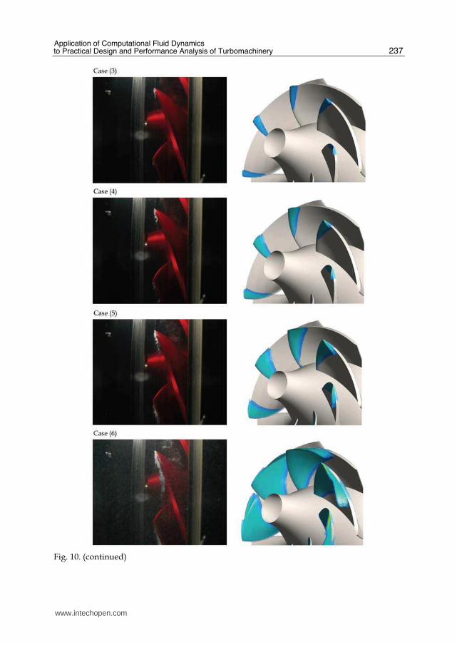
impeller leading edge. With further reduction up to case (4) in the cavitation parameter, the
tip-vortex cavitation has been more produced; the generated pump head still remains,
however, constant without severe performance degradation. When the NPSH reaches a
sufficiently low value over the knee of nearly constant head coefficient (for case (6)), the
distortion of the flow pattern, by mixing more tip-vortex and face sheet cavitation with the
www.intechopen.com
Computational Fluid Dynamics
236
Fig. 10. Cavitation performance characteristics of a mixed-flow pump: NPSH curves
www.intechopen.com
Application of Computational Fluid Dynamics to Practical Design and Performance Analysis of Turbomachinery
237
Fig. 10. (continued)
www.intechopen.com
Computational Fluid Dynamics
238
main flow between the impeller blades, extends across the flow channel and consequently
leads to a sudden decrease in the total pressure rise. Comparing with the computational
results, it is observed that the cavitating region is spread out over the suction surface as well
as the leading edge of the impeller blade. By repeating the above procedure for several off-
design flowrates under the same rotational speed, the suction performance curves, NPSH
versus pump head, have been constructed as shown in Fig. 10. It can be seen that the
cavitation performance curves predicted by the CFD code are in good agreement with the
measured data. Meanwhile, it is worth noting that the cavitation on the diffuser blade
surface has not appeared for the cavitating flow regimes, which means that the diffuser
blade design, taking the flow angle leaving the rotating impeller into account, has been
successfully carried out in this study.
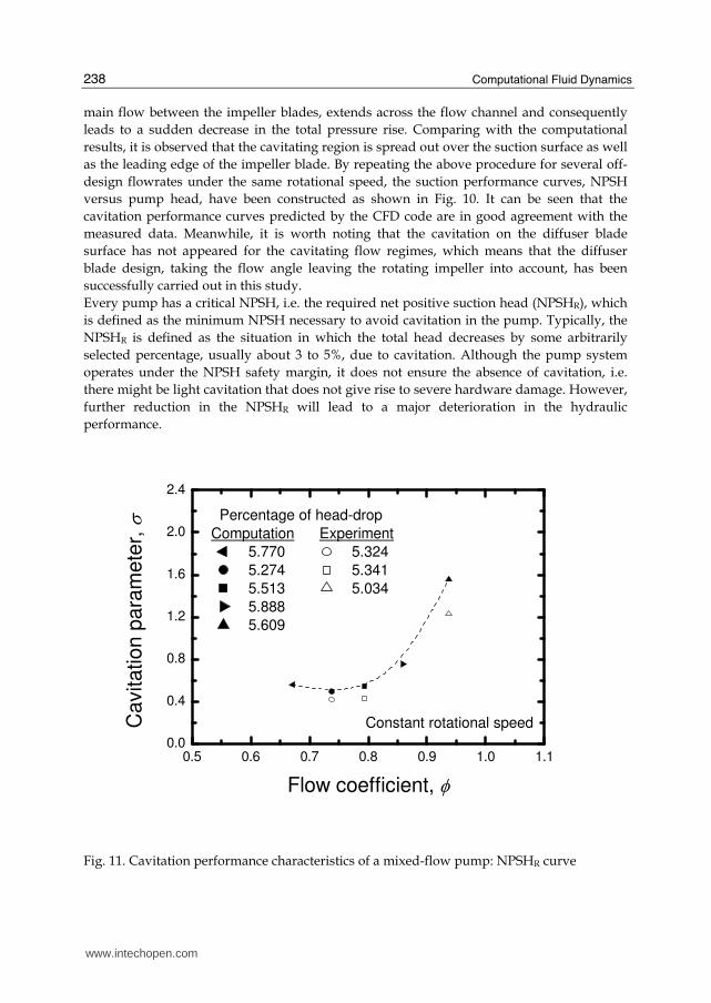
Every pump has a critical NPSH, i.e. the required net positive suction head (NPSHR), which
is defined as the minimum NPSH necessary to avoid cavitation in the pump. Typically, the
NPSHR is defined as the situation in which the total head decreases by some arbitrarily
selected percentage, usually about 3 to 5%, due to cavitation. Although the pump system
operates under the NPSH safety margin, it does not ensure the absence of cavitation, i.e.
there might be light cavitation that does not give rise to severe hardware damage. However,
further reduction in the NPSHR will lead to a major deterioration in the hydraulic
performance.
0.5 0.6 0.7 0.8 0.9 1.0 1.10.0
0.4
0.8
1.2
1.6
2.0
2.4
Percentage of head-drop
Computation Experiment
5.770 5.324
5.274 5.341
5.513 5.034
5.888
5.609
Constant rotational speed
Ca
vita
tio
n p
ara
me
ter,
σ
Flow coefficient, φ
Fig. 11. Cavitation performance characteristics of a mixed-flow pump: NPSHR curve
www.intechopen.com
Application of Computational Fluid Dynamics to Practical Design and Performance Analysis of Turbomachinery
239
This article employs an about 5% head-drop criterion to define the NPSHR for a mixed-flow
pump. Figure 11 shows the performance characteristic curves for the NPSHR under the
operating flowrate conditions. From this figure, it is noted that the NPSHR for a newly
designed pump with the highest pump efficiency is minimized near the design flowrate
regime.
5. Conclusions
A practical design and performance analysis procedure of a mixed-flow pump, in which the
conceptual approach to turbomachinery design using the meanline analysis is followed by
the detailed design and analysis based on the verified CFD code, has been presented in this
Chapter. Performance curves predicted by a coupled CFD code were compared with the
experimental data of a designed, hydrodynamically efficient, mixed-flow pump. The results
agree fairly well with the measured performance curves over the entire operating
conditions. A study for the cavitation performance characteristic curves of a mixed-flow
pump has also been successfully carried out, although further research is definitely needed
to suppress the tip-vortex cavitation under the normal condition.
The design and predictive procedure, including cavitation, employed throughout this study
can serve as a reliable tool for the detailed design optimization and assist in the
understanding of the operational characteristics of general purpose hydraulic and
compressible flow turbomachinery.
6. Acknowledgements
The author would like to thank Dr. E S YOON of the Korea Institute of Machinery
and Materials (KIMM) for his advice and support and it is also gratefully acknowledged
that Dr. K S KIM and Dr. J W AHN of the Maritime and Ocean Engineering Research
Institute (MOERI) provide the experimental data for a mixed-flow pump to publish this
Chapter.
7. References
Aungier, R. H. (2000). Centrifugal Compressors: A Strategy for Aerodynamic Design and
Analysis, American Society of Mechanical Engineers Press, ISBN 0791800938, New
York
Balje, O. E. (1981). Turbomachines: A Guide to Design, Selection, and Theory, John Wiley, ISBN
0471060364, New York
Japikse, D. (1994). Introduction to Turbomachinery, Concepts ETI, ISBN 0933283067,
Norwich
Neumann, B. (2005). The Interaction between Geometry and Performance of a Centrifugal Pump,
John Wiley, ISBN 0852987552, New York
Oh, H. W. & Kim, K-Y. (2001). Conceptual design optimization of mixed-flow pump
impellers using mean streamline analysis. Proc. IMechE, Part A: J. Power and Energy,
215, A1, 133-138, ISSN 09576509
www.intechopen.com

Computational Fluid Dynamics
240
Stepanoff, A. J. (1993). Centrifugal and Axial Flow Pumps: Theory, Design, and Application,
Krieger Publishing Company, ISBN 0894647237, Florida
www.intechopen.com
Computational Fluid DynamicsEdited by Hyoung Woo Oh
ISBN 978-953-7619-59-6Hard cover, 420 pagesPublisher InTechPublished online 01, January, 2010Published in print edition January, 2010
InTech EuropeUniversity Campus STeP Ri Slavka Krautzeka 83/A 51000 Rijeka, Croatia Phone: +385 (51) 770 447 Fax: +385 (51) 686 166www.intechopen.com
InTech ChinaUnit 405, Office Block, Hotel Equatorial Shanghai No.65, Yan An Road (West), Shanghai, 200040, China
Phone: +86-21-62489820 Fax: +86-21-62489821
This book is intended to serve as a reference text for advanced scientists and research engineers to solve avariety of fluid flow problems using computational fluid dynamics (CFD). Each chapter arises from a collectionof research papers and discussions contributed by the practiced experts in the field of fluid mechanics. Thismaterial has encompassed a wide range of CFD applications concerning computational scheme, turbulencemodeling and its simulation, multiphase flow modeling, unsteady-flow computation, and industrial applicationsof CFD.
How to referenceIn order to correctly reference this scholarly work, feel free to copy and paste the following:
Hyoung Woo OH (2010). Application of Computational Fluid Dynamics to Practical Design and PerformanceAnalysis of Turbomachinery, Computational Fluid Dynamics, Hyoung Woo Oh (Ed.), ISBN: 978-953-7619-59-6, InTech, Available from: http://www.intechopen.com/books/computational-fluid-dynamics/application-of-computational-fluid-dynamics-to-practical-design-and-performance-analysis-of-turbomac

© 2010 The Author(s). Licensee IntechOpen. This chapter is distributedunder the terms of the Creative Commons Attribution-NonCommercial-ShareAlike-3.0 License, which permits use, distribution and reproduction fornon-commercial purposes, provided the original is properly cited andderivative works building on this content are distributed under the samelicense.