applying electromagnetic field analysis to minimize the
TRANSCRIPT
Progress In Electromagnetics Research M, Vol. 96, 157–167, 2020
Applying Electromagnetic Field Analysis to Minimize the Earth
Resistance on High Resistivity Soils
Silvia Ronda*, Clara Oliver, Oibar Martinez, Patricia Marquez, and Jose M. Miranda
Abstract—Different optimization strategies to reduce the earth resistance in a high resistivity soil arediscussed in this work and illustrated with a practical example. Finite Element simulations reproducingreal-world conditions in terms of structure design and soil profiles have been made to evaluate theimprovements that should be adopted to minimize earth resistance. We analyze an example of anearthing system of an array of four identical telescopes installed on high resistivity (kΩ·m order) soilswith two different behaviors. In the first one, current dissipation occurs in an uniform soil. In the secondone, a terrain with four layers of different resistivities is considered. This situation corresponds to areal world case of an observatory constructed in a volcanic terrain. It was found that the best strategyin each case differs: extend horizontal electrodes as far as possible from the foundation in the first caseand combine these electrodes with buried vertical electrodes that connect with deep high conductivelayers in the second. The results are discussed in terms of the achieved improvements depending on themodifications introduced in the main structure.
1. LOWERING THE EARTH RESISTANCE: MOTIVATION AND OVERVIEW
The earth electrical resistance plays a major role in the safety of both personnel and instrumentation.Grounding is also a fundamental part of any lightning protection system. It is vitally important,as explained in the standards related to lightning protection [1–4] that in the event of a lightningstrike, excess charge induced in the lightning rods finds a safe and low resistance path to follow for itscorrect dissipation in order to prevent any damage. Moreover, a high earth resistance may compromisethe proper operation of the surge protection devices. It is therefore understandable that a number ofstandards that regulate the implementation of grounding are within the framework of protection againstatmospheric discharges.
Local regulations not always pose specific limits to a maximum acceptable earth resistance. Thisis the case of the Low Voltage Electrotechnical Regulation. For this standard, the maximum earthresistance will be the one which ensures that, throughout the life of the installation and at any timeof the year, touch voltages greater than 24 V cannot be produced in the accessible metal parts of theinstallation, being 50 V for the rest of the parts [5]. But even in these cases one should note that touchand step voltages are better controlled with low earth resistances.
European standards such as EN-62305-3 [3] recommend specific limits to earth resistance, less than10 Ω when being measured at low frequency. However, in EN-62305-3 it is also mentioned that therecommended value of the global earth resistance of 10 Ω is quite conservative in the case of structuresin which direct equipotential bonding is applied. It also remarks that, although the value of resistancemust be as low as possible in all cases, the most important measure is the equipotential bonding.
The standard improvements which can be made to reduce the earth resistance in difficult terrainsare generally based on:
Received 23 July 2020* Corresponding author: Silvia Ronda Penacoba ([email protected]).The authors are with the Department of Matter Structure, Thermal and Electronics Physics, Faculty of Physics, UniversityComplutense of Madrid, Spain.
158 Ronda et al.
a) burying horizontal conductive plates or meshes,b) burying vertical electrodes connected in parallel orc) modifying the own terrain, which can be done by either changing the entire terrain material in a
large volume or adding earthing enhancing compounds.
A combination of several procedures is also possible. For instance, the Taiwan Photon Source (TPS)storage ring has a 0.2 Ω earth system with 62 vertical electrodes and a grid of 4 rings. Bentonite wasused to lower the resistivity of the terrain [6]. Some theoretical models for basic configuration of verticalelectrodes and horizontal grids are adopted in the standards BS 7430:2011 [7] MIL-HDBK-319A [8] andsummarised in [9].
The use of vertical electrodes connected in parallel poses several practical limitations. In orderto prevent loss of effectiveness, it is necessary to keep a minimum distance between electrodes, whichis typically around 5 times larger than the electrode length. Otherwise, the overlapping of the localequipotential lines around each electrode reduces the efficiency of the configuration. Typical electrodelengths can be 2–3 m. The amount of resistance that is reduced with each additional electrode decreasesas the number of electrodes increases, but the basic parallel resistor formula of circuit theory will alwaysunderestimate the final resistance.
It is generally accepted that the electrodes should usually be installed with a backfilling material ofhigh conductivity, which increases the effective diameter. Concrete is hygroscopic and has a resistivityof 30–90 Ω ·m. This is particularly interesting in medium and highly resistive soils because a wire ormetallic rod encased in concrete has lower resistance than a similar electrode buried directly in theearth. Some models of the calculation of the resistance of a grid with encased vertical electrodes canbe found in the IEEE Std 80-2000 [10].
One solution could be replacing the soil with a low resistance material [11]. A number of earthenhancement materials are commercially available. Many are composed of carbon-based materials orclays like bentonite (or a mixture of both). These materials can also be used as backfilling materialsto improve the resistance of an electrode. Chemical treatment of soil has environmental implicationsand should not be considered as a long term solution, and there is additionally a risk of corrodingthe earthing system. Coke breeze has also been used, but it poses serious concerns due to its highlycorrosive nature. IEC 62561-7 standard discusses prequalification methods for ground enhancementmaterials [12].
Bentonite clay is actually a natural earth soil, mostly composed of the mineral montmorillionite,which was formed by volcanic action in the past. It is noncorrosive, stable, and has a resistivity of2.5 Ω ·m at 300% moisture. It has almost no environmental concerns and will not corrode the copperlike other compounds based on carbon. Bentonite is hygroscopic, but just because of this it needsmoisture in the ground to maintain its properties.
Some earthing enhancement materials contain cement, which after installation acquire propertiesthat are very close to concrete. This prevents the material from leaching into the soil or washingaway by groundwater. This type of material does not require any maintenance and has been shown tosignificantly reduce the long-term resistance of grounding electrodes in a study commissioned by theNational Fire Protection Research Foundation [13]. However, alternatives should be considered becausethese solutions could not be feasible in terms of environmental conservation and costs. This could bethe case when earthing must be done in areas of difficult access and with soils that are hard to excavate.
2. A CASE STUDY: LST SUBARRAY OF CTA-NORTH PROJECT
In order to illustrate how the electromagnetic field analysis can help to optimize the design of an earthingsystem, we analyze a practical example with challenging demands: The earthing system of an array offour telescopes built in a soil of volcanic nature and very low humidity content.
Cherenkov Telescope Array (CTA) North Project aims to build a large scale observatory hostingfour Large-Sized Telescopes (LST) and another subarray of smaller, Medium-Sized Telescopes (MST).CTA-North subarrays are located in the Roque de los Muchachos Observatory, a protected area withregulations that pose severe limits to land removal operations and uses of earth enhancement compounds.

Progress In Electromagnetics Research M, Vol. 96, 2020 159
2.1. Description of the Telescopes
The LST is an instrument with a mechanical structure hosting several sensitive optical and electronicssubsystems. Figure 1 shows a picture of the localization of all the LST (1-4) and a photo of the firsttelescope built in the observatory, the LST1.
(a) (b)
Figure 1. Current view of the localization of (a) the four LSTs and (b) photo of LST1.
LST supports an array of 198 mirror plates, which conform a parabolic dish of 23 m diameter. Themirror plates are mounted on a structure of tubes. Tubes are composed of galvanized steel, aluminium,and carbon fibre. Each mirror can be moved with two actuators. The mirrors focus the light on acamera composed by an array of fast photomultipliers and associated electronics, and the recorded dataare sent via optical fibres to a control room for further processing and storage.
The camera is the most complex system of the telescope and has two input power lines: one phase230 V UPS and 3 phases AC 400 V. Inside the camera, both lines feed the main power distribution box,which contains surge protection devices. The UPS line feeds those elements that need power for safetyreasons in case of a power failure. The other one feeds the rest of the camera subsystems either directlyor through 24 V power supplies.
The telescope structure rests on seven points, with the central axis of rotation and six movingbogies equally spaced in a hexagonal arrangement. The bogies run on a circular rail of 23.9 m diameterand 500 mm width, which is fixed to the terrain with a concrete foundation. The total weight of LSTtelescope is 103 tons [14, 15].
2.2. Soil Conductivity Surveys
During the earthing system design, soil conductivity was one of the elements that received specialattention, since it has an important influence on earth resistance value [16, 17]. In practice, earthresistance is roughly inversely proportional to soil conductivity. This parameter was measured for thefour telescope sites using Wenner method [18]. A significant diversity of values was found among thesites, and all of them exhibited conductivities below 1 mS/m. All sites except LST3 showed uniformconductivity up to depths of 10 m. However, in LST3 the terrain corresponds to a non-homogeneous soilwith extremely low conductivity layers due the presence of fractured basalt rocks. The depth, thickness,and conductivity of each layer were estimated by correlating geotechnical surveys with finite elementsimulations of the Wenner method. An agreement with measurements was obtained within 10% errormargin [19]. Table 1 shows the final values of the soil conductivities for all LST sites.
2.3. Foundation and Baseline Design of the Earthing System
The foundations of the telescopes are made of concrete and a steel bar armature. They have a centralpart of reinforced concrete under the axis of rotation of the telescope. A circular beam of reinforced

160 Ronda et al.
Table 1. Soil resistivity and geometrical parameters of the soil considered in models for LST telescopes.
Layer depth (m) σ (S/m) Layer depth (m) σ (S/m)LST1 0–∞ 6.67 10−4
LST2 0–∞ 1.95 10−4
0–2.85 0.54 10−4
LST32.85–4.75 2.86 10−4
4.75–6.25 0.65 10−4 LST4 0–∞ 4.08 10−4
6.25–∞ 6.67 10−4
concrete is under the rail, and it is connected to the central part with radial beams. Another nearbyreinforced concrete foundation is under the camera access tower [20], which is a metallic tower speciallydesigned for two purposes: facilitate the camera maintenance and improve the anchorage of the telescopeduring storms. In terms of safety, the LST structure has to be equipotential [3, 4, 21].
The design of the LST1 earthing system with the sketch of the metal plate structure is illustratedin Figure 2.
Figure 2. Schematic of the real earthing system designed for LST telescopes. Magenta lines indicatethe structure of the horizontal plates used for earthing.
The steel armature of the foundation is connected with metal plates, which are extended outsidethe reinforced concrete in the four cardinal directions. The metal plates are also connected to the metalstructure of the telescope. Lightning rods are integrated in the LST1 structure and the upper level ofthe camera access tower. They are connected to the earthing system by stainless steel cables whichmerge in an earth pit with a lightning counter. From this pit, an extension of the earth system wasmade with a copper plate ended in three additional plates arranged as a goose radial leg and located inthe eastern side of the telescope. This installation is done according to UNE standard [22].
3. FINITE ELEMENT SIMULATION
Finite Element Method (FEM) has been used to calculate the earth resistance of the telescopes undertest: LST1 and LST3. LST2 and LST4 sites feature a uniform resistivity soil, like LST1. Therefore,as all telescopes are identical the results for LST1 can be rescaled with the resistivities to obtain theexpected earth resistances of LST2 and LST4 without additional simulations. FEM simulations weredone with COMSOL Multiphysics v5.3a software. For the models presented in this work, ElectricCurrents Module and a stationary study have been used.
The computational domain is a 3D hemisphere that contains the complete geometry modeled forthe earthing system of the telescopes. Soil below earth resistance installation is designed with thecharacteristics displayed in Table 1. Thus, an homogeneous terrain is considered in LST1 case and afour layer model in LST3, as can be seen in the illustrations of Figure 3.
Progress In Electromagnetics Research M, Vol. 96, 2020 161
(a) (b)
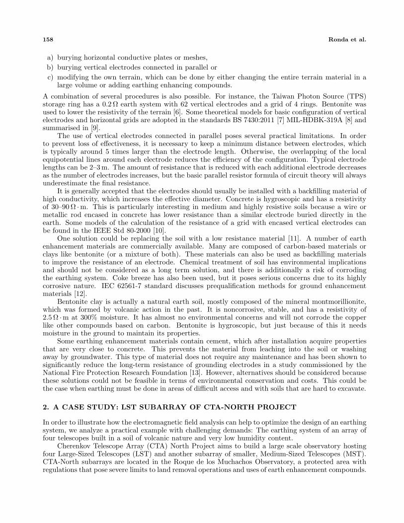
Figure 3. Implemented model geometry and conductivity parameters of the soil. (a) LST1 and (b)LST3.
The earthing system modeled, based on the real one, has two main parts:
- The metal grid. This consists of two solid blocks. One of them is located under the telescopecamera and the other under the mirror.
- A composition of thin metal plates. They are surrounding and connected to the solid blocks.
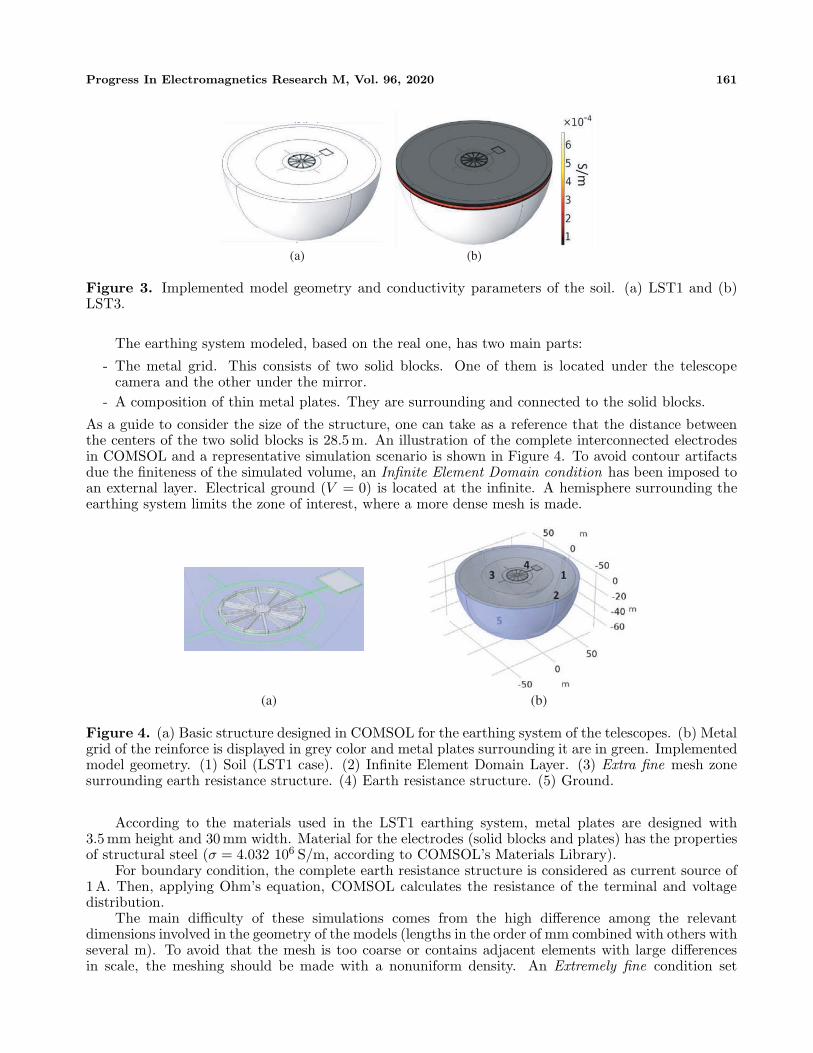
As a guide to consider the size of the structure, one can take as a reference that the distance betweenthe centers of the two solid blocks is 28.5 m. An illustration of the complete interconnected electrodesin COMSOL and a representative simulation scenario is shown in Figure 4. To avoid contour artifactsdue the finiteness of the simulated volume, an Infinite Element Domain condition has been imposed toan external layer. Electrical ground (V = 0) is located at the infinite. A hemisphere surrounding theearthing system limits the zone of interest, where a more dense mesh is made.
(a) (b)
Figure 4. (a) Basic structure designed in COMSOL for the earthing system of the telescopes. (b) Metalgrid of the reinforce is displayed in grey color and metal plates surrounding it are in green. Implementedmodel geometry. (1) Soil (LST1 case). (2) Infinite Element Domain Layer. (3) Extra fine mesh zonesurrounding earth resistance structure. (4) Earth resistance structure. (5) Ground.
According to the materials used in the LST1 earthing system, metal plates are designed with3.5 mm height and 30 mm width. Material for the electrodes (solid blocks and plates) has the propertiesof structural steel (σ = 4.032 106 S/m, according to COMSOL’s Materials Library).
For boundary condition, the complete earth resistance structure is considered as current source of1A. Then, applying Ohm’s equation, COMSOL calculates the resistance of the terminal and voltagedistribution.
The main difficulty of these simulations comes from the high difference among the relevantdimensions involved in the geometry of the models (lengths in the order of mm combined with others withseveral m). To avoid that the mesh is too coarse or contains adjacent elements with large differencesin scale, the meshing should be made with a nonuniform density. An Extremely fine condition set
162 Ronda et al.
by COMSOL was chosen for the thin plates, an Extra fine condition for the solid blocks and thesurrounding soil (zone 3 in Figure 4). Finally, the other domains are meshed with Normal condition.Additionally, the external layer of the hemisphere has a special distribution appropriated for contourdomains called Boundary Layers. Despite this differentiation, it was necessary to adjust the tetrahedralelement minimum size because some domains are too narrow with respect to the rest of the geometry,and very short boundary segments were necessary. On average, a quality factor of 0.5 is achieved in allmodels.
4. RESULTS AND DISCUSSION
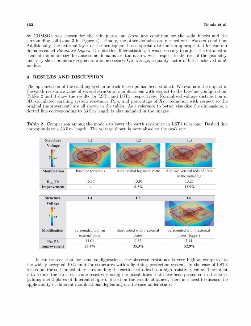
The optimization of the earthing system in each telescope has been studied. We evaluate the impact inthe earth resistance value of several structural modifications with respect to the baseline configuration.Tables 2 and 3 show the results for LST1 and LST3, respectively. Normalized voltage distribution in3D, calculated earthing system resistance RES, and percentage of RES reduction with respect to theoriginal (improvement) are all shown in the tables. As a reference to better visualize the dimensions, adotted line corresponding to 53.5 m length is also included in the images.
Table 2. Comparison among the models to lower the earth resistance in LST1 telescope. Dashed linecorresponds to a 53.5 m length. The voltage shown is normalised to the peak one.
StruVo
Modi
R Impro
ucture oltage
ification
ES (Ω) ovement
1.1
Baseline (o
15.1
-
1
original)
7
Add a radia
1.2
al leg metal pl
13.91
8.3%
late Add tw
1.3
wo vertical rodin the radial
13.27
12.5%
ds of 10 mleg
StruVo
Modi
Impro
ucture oltage
ification
ovement
1.4
Surroundedexternal
11.0
27.4
4
d with an plate
01
%
Surroundedp
1.5
d with 3 externplates 9.82
35.3%
nal Surro
1.6
ounded with 3plates (bigge
7.14
52.9%
external er)
R ES (Ω)
It can be seen that for some configurations, the observed resistance is very high as compared tothe widely accepted 10 Ω limit for structures with a lightning protection system. In the case of LST3telescope, the soil immediately surrounding the earth electrodes has a high resistivity value. The intentis to reduce the earth electrode resistivity using the possibilities that have been presented in this work(adding metal plates of different shapes). Based on the results obtained, there is a need to discuss theapplicability of different modifications depending on the case under study.

Progress In Electromagnetics Research M, Vol. 96, 2020 163
Table 3. Comparison among the models to lower the earth resistance in LST3 telescope. Dashed linecorresponds to a 53.5 m length. The voltage shown is normalised to the peak one.
StruVo
Modi
R
Impro
StruVo
Modi
Impro
ucture oltage
ification
ES (Ω) ovement
ucture oltage
ification
ovement
2.1
Basic (ori
69.2
-
2.4
Surroundedexternal pla
vertical 27.9
59.7
iginal)
23
4
d with an ate with 7
rods 90
%
Surrounded
2
Surroundedplate with 7
plates of
2.2
d with an exterplate 53.46
22.8%
2.5
d with an exter vertical rods f 60 cm (x20)25.51
63.1%
rnal Surroplat
rnal and
Surroplate
2.3
unded with ane with 3 vertic
37.87
45.3%
2.6
unded with ane with 22 verti
23.58
64.2%
n external cal rods
n external ical rods
RES (Ω)
4.1. Systems with Horizontal Plates
When the earth resistance is not low enough, lengthening the horizontal earth electrodes in the soil isa popular solution [23]. The comparison of 1.4 with 1.6 indeed reveals the effectivity of extending theplates away from the main structure, to favor the dissipation of the electric current in a larger surface.When all plates are located too close from each other, the decrease of the resistance is marginal. Thiscan be illustrated by comparing 1.5 configuration with 1.4. Despite the addition of two external plates,the improvement is only 7.9%. This result agrees well with previous works which show that resistancein designs with higher density of rods in the center of the grounding grid is often higher than thosedesigns that place the rods at the grid periphery [24]. This is attributed to the shielding effect betweenelectrodes.
The use of radial plates usually improves the resistance of the earthing system, by allowing currentto diverge on each conductor, offering lower impedance [25]. This technique seems more effective thana single long conductor. It is also recommended to install at least one vertical electrode per radialconductor when it can connect to a lower resistivity soil layer [26]. In our case, both scenarios 1.2 and1.3 consider this case. The radial “goose leg” added in 1.2 has a resistance of 54.24 Ω as calculatedwith COMSOL. Since this value is high as compared to the 15.17 Ω of the main structure, it does notcontribute that much to the decrease. For this reason, adding vertical electrodes in this part of thestructure is not the optimal solution in terms of improvement (4.2%) and cost.
The discussion for nonuniform soils is more complex. The difference of current distributions in thelayers rises when reflective coefficient increases due the resistivity value change in the interfaces. Inour case, we have a high resistivity upper layer. It seems that lower earth resistance can be obtainedthrough matching deep low resistivity materials, i.e., with vertical electrodes. If we compare 2.1 and 2.2cases, a significant improvement is achieved (22.8%), but installing additional and/or wider horizontalplates (case 2.5) does not result into a noticeable effect as compared to previous models. The high

164 Ronda et al.
resistivity of the terrain heavily influences the resistance of the structure and imposes a limit to thecurrent dissipation in this first layer. In this case, connecting electrodes with the best conductive layersis the most effective strategy.
4.2. Systems with Horizontal Plates Combined with Vertical Electrodes
The periphery of the earth system is the best place to insert vertical electrodes [27]; therefore, this wasthe place chosen for the simulation trials. In LST1, structure 1.3 did not show a noticeable improvementwith 10 m long metal plates in the end of the radial leg. To evaluate how effective is for this case to buryvertical electrodes in the earthing system, we studied the effect of adding to structure 1.6 plates of 10 m.We added 2, 4, 6 (structure 1.7), 8 10, 12 (structure 1.8) and 16 electrodes. Results and representativeillustrations are shown in Figure 5.
1.77 1.8
Figure 5. Relationship between the number of vertical electrodes added to structure 1.6 and thecalculated earth resistance RES. Illustration of the cases with 6 vertical electrodes (1.7) and 12 (1.8).
We can confirm that resistance decreases with the increase of the number of vertical electrodes.However, the tendency shows that a saturation is expected when the number of electrodes is very high,because the shielding effect increases [27, 28].
On a multilayered soil, the method of long vertical electrodes does not improve the situation whenthe soil resistivity of the bottom layer is very high. On the other hand, when a low resistivity soillayer is under a higher one, adding deep electrodes can achieve good results. The comparison of 2.2with 2.3 and 2.4 shows that long vertical electrodes can always reach better results. However, in 2.6we have increased the number of vertical electrodes up to 22, and the enhancement is not as noticeableas desired. This could be related with the current reflections produced due to resistivity interfaces. So,the choice of electrode length, location, and number is determined by the soil structure.
4.3. Simulations of Parallel Connection of Earthing Systems
The large resistivity of the LST3 site is the main factor limiting the earth resistance minimization forthis telescope. However, the fact that the four LSTs are far enough from each other offers the possibilityof efficiently reducing the earth resistance by interconnecting all the earth layouts, which in practicemeans a connection of four resistors in parallel. According to previous work on the behavior of verticalelectrodes connected in parallel, the electrodes must be separated from each other at least five times oftheir equivalent radius, so the ground potential has decayed to 20% of the potential rise [29]. However,this result cannot be applied in a straightforward way to the connection of the LST earth systems fortwo main reasons: the optimum layouts for uniform terrains are very shallow, and it is unclear whatwould be the influence of the non-uniformity of the LST3 soil resistivity.
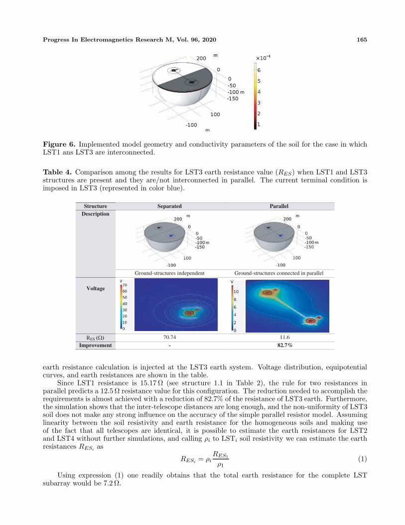
In order to clarify these points a simulation was done by considering a structure in which LST1and LST3 earth systems are connected, taking into account the different soil resistivities under them.Figure 6 shows a schematic of the model geometry.
The calculations using FEM are presented in Table 4. In the first column, the case in which bothstructures are present but not inter-connected is shown. In the second column, we connect them withan horizontal steel plate similar to the one used in the previous designs. The current source for the
Progress In Electromagnetics Research M, Vol. 96, 2020 165
Figure 6. Implemented model geometry and conductivity parameters of the soil for the case in whichLST1 ans LST3 are interconnected.
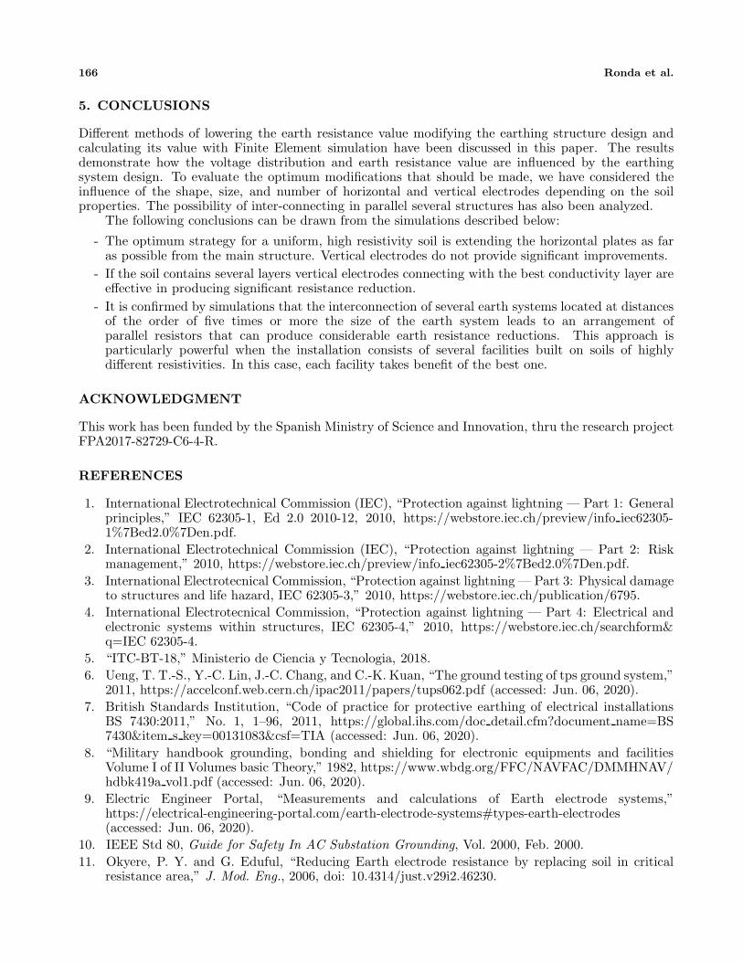
Table 4. Comparison among the results for LST3 earth resistance value (RES) when LST1 and LST3structures are present and they are/not interconnected in parallel. The current terminal condition isimposed in LST3 (represented in color blue).
Structure Separated Parallel Description
Ground-structures independent Ground-structures connected in parallel
Voltage
RES (Ω) 70.74 11.6
Improvement - 82.7%
earth resistance calculation is injected at the LST3 earth system. Voltage distribution, equipotentialcurves, and earth resistances are shown in the table.
Since LST1 resistance is 15.17 Ω (see structure 1.1 in Table 2), the rule for two resistances inparallel predicts a 12.5 Ω resistance value for this configuration. The reduction needed to accomplish therequirements is almost achieved with a reduction of 82.7% of the resistance of LST3 earth. Furthermore,the simulation shows that the inter-telescope distances are long enough, and the non-uniformity of LST3soil does not make any strong influence on the accuracy of the simple parallel resistor model. Assuminglinearity between the soil resistivity and earth resistance for the homogeneous soils and making useof the fact that all telescopes are identical, it is possible to estimate the earth resistances for LST2and LST4 without further simulations, and calling ρi to LSTi soil resistivity we can estimate the earthresistances RESi as
RESi = ρiRES1
ρ1(1)
Using expression (1) one readily obtains that the total earth resistance for the complete LSTsubarray would be 7.2 Ω.
166 Ronda et al.
5. CONCLUSIONS
Different methods of lowering the earth resistance value modifying the earthing structure design andcalculating its value with Finite Element simulation have been discussed in this paper. The resultsdemonstrate how the voltage distribution and earth resistance value are influenced by the earthingsystem design. To evaluate the optimum modifications that should be made, we have considered theinfluence of the shape, size, and number of horizontal and vertical electrodes depending on the soilproperties. The possibility of inter-connecting in parallel several structures has also been analyzed.
The following conclusions can be drawn from the simulations described below:
- The optimum strategy for a uniform, high resistivity soil is extending the horizontal plates as faras possible from the main structure. Vertical electrodes do not provide significant improvements.
- If the soil contains several layers vertical electrodes connecting with the best conductivity layer areeffective in producing significant resistance reduction.
- It is confirmed by simulations that the interconnection of several earth systems located at distancesof the order of five times or more the size of the earth system leads to an arrangement ofparallel resistors that can produce considerable earth resistance reductions. This approach isparticularly powerful when the installation consists of several facilities built on soils of highlydifferent resistivities. In this case, each facility takes benefit of the best one.
ACKNOWLEDGMENT
This work has been funded by the Spanish Ministry of Science and Innovation, thru the research projectFPA2017-82729-C6-4-R.
REFERENCES
1. International Electrotechnical Commission (IEC), “Protection against lightning — Part 1: Generalprinciples,” IEC 62305-1, Ed 2.0 2010-12, 2010, https://webstore.iec.ch/preview/info iec62305-1%7Bed2.0%7Den.pdf.
2. International Electrotechnical Commission (IEC), “Protection against lightning — Part 2: Riskmanagement,” 2010, https://webstore.iec.ch/preview/info iec62305-2%7Bed2.0%7Den.pdf.
3. International Electrotecnical Commission, “Protection against lightning — Part 3: Physical damageto structures and life hazard, IEC 62305-3,” 2010, https://webstore.iec.ch/publication/6795.
4. International Electrotecnical Commission, “Protection against lightning — Part 4: Electrical andelectronic systems within structures, IEC 62305-4,” 2010, https://webstore.iec.ch/searchform&q=IEC 62305-4.
5. “ITC-BT-18,” Ministerio de Ciencia y Tecnologia, 2018.6. Ueng, T. T.-S., Y.-C. Lin, J.-C. Chang, and C.-K. Kuan, “The ground testing of tps ground system,”
2011, https://accelconf.web.cern.ch/ipac2011/papers/tups062.pdf (accessed: Jun. 06, 2020).7. British Standards Institution, “Code of practice for protective earthing of electrical installations
BS 7430:2011,” No. 1, 1–96, 2011, https://global.ihs.com/doc detail.cfm?document name=BS7430&item s key=00131083&csf=TIA (accessed: Jun. 06, 2020).
8. “Military handbook grounding, bonding and shielding for electronic equipments and facilitiesVolume I of II Volumes basic Theory,” 1982, https://www.wbdg.org/FFC/NAVFAC/DMMHNAV/hdbk419a vol1.pdf (accessed: Jun. 06, 2020).
9. Electric Engineer Portal, “Measurements and calculations of Earth electrode systems,”https://electrical-engineering-portal.com/earth-electrode-systems#types-earth-electrodes(accessed: Jun. 06, 2020).
10. IEEE Std 80, Guide for Safety In AC Substation Grounding, Vol. 2000, Feb. 2000.11. Okyere, P. Y. and G. Eduful, “Reducing Earth electrode resistance by replacing soil in critical
resistance area,” J. Mod. Eng., 2006, doi: 10.4314/just.v29i2.46230.
Progress In Electromagnetics Research M, Vol. 96, 2020 167
12. “IEC 62561-7:2018 Lightning protection system components (LPSC) — Part 7: Requirementsfor earthing enhancing compound,” International Standard, 2018, https://webstore.iec.ch/publication/33885 (accessed: Jun. 06, 2020).
13. Lindsay, T., “National electrical grounding research project, technical report,” 2007,https://www.nfpa.org/-/media/Files/News-and-Research/Archived-reports/negrpfinalreport.ashx?la=en.
14. “LST — Cherenkov telescope array,” https://www.cta-observatory.org/project/technology/lst/(accessed: Jun. 15, 2020).
15. Cortina, J. and M. Teshima, “Status of the Cherenkov telescope array’s large size telescopes,” 2015,http://cta-observatory.org (accessed: Jun. 15, 2020).
16. Sabiha, N. A. and N. I. Elkalashy, “Evaluation of grounding system design for wind farm usingCOMSOL,” 2018, http://www.ripublication.com (accessed: Jun. 26, 2020).
17. Malanda, S. C., I. E. Davidson, E. Singh, and E. Buraimoh, “Analysis of soil resistivity and itsimpact on grounding systems design,” 2018 IEEE PES/IAS PowerAfrica, PowerAfrica 2018, 324–329, Nov. 2018, doi: 10.1109/PowerAfrica.2018.8520960.
18. Wenner, F., “A Method of measuring Earth resistivity,” Bull. Bur. Stand., Vol. 12, 469–478, 1916,doi: https://doi.org/10.6028/bulletin.282.
19. Ronda, S., O. Martinez, C. Oliver, P. Marquez, and J. M. Miranda, “Finite element analysis andexperimental characterization of soil electrical resistivity at El roque de los muchachos observatory,”Journal of Electromagnetic Analysis and Applications, Vol. 12, No. 7, 89–102, 2020.
20. De A. de Canarias, I., “LIC-15-034: Construction of foundation of Telescope LST1,”10, Plataforma de Contratacion del Estado (Spain), 2015, https://contrataciondelestado.es/wps/wcm/connect/8e64f971-f3eb-41d1-a206-edca7ec9b590/DOC CD2015-229760.pdf?MOD=AJPERES (accessed: Jun. 15, 2020).
21. Ma, J., T. Del Pino, and S. P. Martı, “NTP-1.084: Prevencion de riesgos laborales originados porla caıda de rayos,” 2017.
22. “UNE 21186:2011 Proteccion contra el rayo: Pararrayos con dispo,” 2011, https://www.aenor.com/normas-y-libros/buscador-de-normas/une/?Tipo=N&c=N0048559 (accessed: Jun. 25, 2020).
23. El-Sayed Gouda, O., Design Parameters of Electrical Network Grounding Systems, IGI Global,2018.
24. Zeng, R., J. He, Z. Wang, Y. Gao, W. Sun, and Q. Su, “Analysis on influence of longvertical grounding electrodes on grounding system for substation,” PowerCon 2000 — 2000International Conference on Power System Technology, Proceedings, Vol. 3, 1475–1480, 2000, doi:10.1109/ICPST.2000.898188.
25. El-Sayed Gouda, O., Design Parameters of Electrical Network Grounding Systems, IGI Global,2018.
26. Lim, S. C., C. Gomes, and M. Z. A. Ab Kadir, “Electrical earthing in troubled environment,” Int.J. Electr. Power Energy Syst., Vol. 47, No. 1, 117–128, May 2013, doi: 10.1016/j.ijepes.2012.10.058.
27. Zeng, R., J. He, Z. Wang, Y. Gao, W. Sun, and Q. Su, “Analysis on influence of longvertical grounding electrodes on grounding system for substation,” PowerCon 2000 — 2000International Conference on Power System Technology, Proceedings, Vol. 3, 1475–1480, 2000, doi:10.1109/ICPST.2000.898188.
28. Malanda, S. C., I. E. Davidson, E. Singh, and E. Buraimoh, “Analysis of soil resistivity and itsimpact on grounding systems design,” 2018 IEEE PES/IAS PowerAfrica, PowerAfrica 2018, 324–329, Nov. 2018, doi: 10.1109/PowerAfrica.2018.8520960.
29. Mitolo, M., Analysis of Grounding and Bounding Systems, CRC Press, 2020.