approach-and-landing accidents reductionpicma.info/sites/default/files/documents/background/airbus...
TRANSCRIPT
getting to grips with
Approach-and-Landing Accidents Reduction
A Flight Operations View
Issue 1
October 2000
AIRBUS INDUSTRIE
Flight Operations Support – Customer Services Directorate

Getting to Grips with Approach-and-Landing Accidents Reduction
Terms of Reproduction
AIRBUS 2002 – All Rights Reserved
The statements made herein do not constitute an offer. They are expressed on the assumptions shown and are expressed in good faith. Where the supporting grounds for these statements are not shown the Company will be pleased to explain the basis thereof.
In the interest of aviation safety, Airbus encourages the wide use of the ALAR Briefing Notes ( in printed format or in electronic format ) as suggested in the chapter Introducing the Briefing Notes ( Page 2 – How to Use and Implement the Briefing Notes ? ).
Use and duplication (in whole or part, in all media) of the ALAR Briefing Notes is authorized for internal purposes of the users. Any commercial use is strictly excluded.
The users shall reproduce the copyright “ AIRBUS 2002 – All Rights Reserved ” of the copyright owner on any duplication.
Duplications shall credit Airbus and the Flight Safety Foundation, for any reference to or use of the contents of the ALAR Briefing Notes, that have been developed by Airbus in the frame of an international industry task force led by the Flight Safety Foundation.
In case of translation, the translation shall not modify the intent and spirit of the original text.
In case of partial reprint, the abstract shall not alter the contents from its original context.
The ALAR Briefing Notes are provided under the expressed condition that Airbus shall have no liability or responsibility for the use of the ALAR Briefing Notes, the correctness of the duplication, adaptation or translation and for the updating and revision of any duplicated version.
For any further information or assistance, do not hesitate to contact us.
Training and Flight Operations Support & Line Assistance
Customer Services Directorate
Attention Michel TREMAUD Operational Standards and Flight Safety Projects
1, Rond Point Maurice Bellonte, BP 33
31707 BLAGNAC Cedex – FRANCE
Telex : AIRBU 530526F
SITA : TLSBI7X
Telefax : +(33).5.61.93.29.68 or +(33).5.61.93.44.65
E-mail : michel.tremaud @ airbus.fr

AIRBUS INDUSTRIE Getting to Grips with Flight Operations Support Approach-and-Landing Accidents Reduction
The brochure Getting to Grips with Approach and Landing Accidents Reduction provides an overview of the flying techniques and operational aspects involved in approach-and-landing accidents. The brochure consists of a set of Approach-and-Landing Briefing Notes. Each Briefing Note:
• Presents the subject using statistical data;
• Emphasizes the applicable standards and best practices (standard operating procedures, supplementary techniques, operational recommendations and training guidelines);
• Discusses the factors that may lead flight crews to deviate from relevant standards (for eye-opening purposes);
• Provides or suggests company’ accident-prevention-strategies and/or personal lines-of-defense (for incident/accident prevention purposes and/or for correction purposes);
• Establishes a summary of operational and training key points;
• Provides cross-reference to the associated or related Briefing Notes; and,
• References the relevant ICAO, U.S. FAR and European JAR documents.
Should any deviation appears between the information provided in this brochure and that published in the applicable Airplane Flight Manual (AFM), Flight Crew Operating Manual (FCOM), Quick Reference Handbook (QRH) and Flight Crew Training Manual (FCTM), the latter shall prevail at all times.
All readers are encouraged to submit their questions and suggestions, regarding this document, to the following address :
Airbus Industrie
Training and Flight Operations Support Customer Services Directorate
Attention Michel TREMAUD Operational Standards Development
1, Rond Point Maurice Bellonte, BP 33 31707 BLAGNAC Cedex – FRANCE
Telex : AIRBU 530526F
SITA : TLSBI7X Telefax : +(33).5.61.93.29.68 or +(33).5.61.93.44.65
E-mail : michel.tremaud @ airbus.fr
AI/ST-F 94A.0093/00
Foreword

AIRBUS INDUSTRIE Getting to Grips with Flight Operations Support Approach-and-Landing Accidents Reduction
Table of Contents
Page 1
Table of Contents
Foreword Briefing Notes Summary ALAR Task Force – Conclusions and Recommendations Introducing the Briefing Notes Glossary of Terms and Abbreviations Briefing Notes :
1 - Standard Operating Procedures (SOPs)
1.1 - Operating Philosophy
1.2 - Optimum Use of Automation
1.3 - Operations Golden Rules
1.4 - Standard Calls
1.5 - Normal Checklists
1.6 - Approach and Go-around Briefings
2 - Crew Coordination 2.1 - Human Factors in Approach-and-Landing Accidents 2.2 - CRM Issues in Approach-and-landing Accidents 2.3 - Effective Pilot/Controller Communications 2.4 - Intra-Cockpit Communications – Managing Interruptions and Distractions 3 - Altimeter and Altitude Issues 3.1 - Altimeter Setting – Use of Radio Altimeter 3.2 - Altitude deviations 4 - Descent and Approach Management 4.1 - Descent and Approach Profile Management 4.2 - Energy Management during Approach
5 - Approach Hazards Awareness 5.1 - Approach Hazards Awareness - General 5.2 - Terrain Awareness
5.3 - Visual Illusions Awareness
5.4 - Windshear Awareness

AIRBUS INDUSTRIE Getting to Grips with Flight Operations Support Approach-and-Landing Accidents Reduction
Table of Contents
Page 2
6 - Readiness and Commitment to Go-around 6.1 - Being Prepared to Go-around
6.2 - Flying a Manual Go-around
6.3 - Terrain Avoidance ( Pull-up ) Maneuver
6.4 - Bounce Recovery – Rejected Landing 7 - Approach Techniques 7.1 - Flying Stabilized Approaches
7.2 - Flying Constant-Angle non-Precision Approaches
7.3 - Acquisition of Visual References
7.4 - Flying Visual Approaches
8 - Landing Techniques 8.1 - Preventing Runway Excursions and Overruns 8.2 - The Final Approach Speed 8.3 - Factors Affecting Landing Distance 8.4 - Optimum Use of Braking Devices 8.5 - Landing on Wet or Contaminated Runway 8.6 - About Wind Information -
What’s your Current Wind ?
8.7 - Crosswind Landing

AIRBUS INDUSTRIE Getting to Grips with Flight Operations Support Approach-and-Landing Accidents Reduction
Briefing Notes Summary
Page 1
Briefing Notes Summary
Introduction The brochure Getting to Grips with Approach-and-Landing Accidents Reduction provides operational recommendations and guidelines to implement the conclusions and recommendations of the following international working groups:
• Flight Safety Foundation (FSF) – CFIT and Approach-and-Landing Accidents Reduction (ALAR) Task Force; and,
• U.S. Commercial Aviation Safety Team (CAST) – Joint Safety Implementation Team (JSIT) for ALAR.
Statistical Data Approach-and-landing accidents (i.e., accidents that occur during initial approach, intermediate approach, final approach or landing) represent every year 55 % of total hull losses and 50 % of fatalities. These statistical data have not shown any down trend over the past 40 years ! The flight segment from the outer marker to the completion of the landing roll represents only 4 % of the flight time but 45 % of hull losses. The following types of events account for 75 % of approach-and-landing incidents and accidents:
• CFIT (including landing short of runway);
• Loss of control;
• Runway overrun;
• Runway excursion; and,
• Non-stabilized approaches.
The scope of this brochure extends beyond approach-and-landing accidents, by addressing:
• Wind shear awareness in all flight phases, including takeoff and landing;
• Terrain awareness in all flight phases;
• Descent-and-approach preparation;
• Initial descent management; and,
• Go-around and missed-approach. This extended scope addresses the type of events and causal factors involved in approximately 70 % of total hull losses.
Conclusions and Recommendations Operations and Training Issues The conclusions and recommendations of the Flight Safety Foundation ALAR Task Force are appended to this Briefing Notes Summary. These conclusions identify the following operations and training issues as frequent causal factors in approach-and-landing accidents, including those involving CFIT:
• Standard operating procedures;
• Decision-making in time-critical situations;
• Decision to initiate a go-around when warranted;
• Rushed and unstabilized approaches;
• Pilot/controller understanding of each other’ operational environment;
• Pilot/controller communications;
• Awareness of approach hazards (visual illusions, adverse wind conditions or operations on contaminated runway); and,
• Terrain awareness.
AIRBUS INDUSTRIE Getting to Grips with Flight Operations Support Approach-and-Landing Accidents Reduction
Briefing Notes Summary
Page 2
Operational Recommendations and Guidelines Based on the conclusions and recommendations of the FSF and CAST working groups, Airbus Industrie has developed a set of Approach-and-Landing Briefing Notes to provide background information, operational recommendations and training guidelines for the prevention of approach-and-landing incidents and accidents. The Approach-and-Landing Briefing Notes address thirty-three operational and training subjects grouped into eight thematic chapters. The following overview of the Approach-and-Landing Briefing Notes highlights the main operational recommendations and training guidelines applicable for each theme and subject. These recommendations and guidelines should be considered for incorporation in the operator’s operations manual, aircraft operating manual and training manual, and emphasized during transition training, line training, recurrent training, line checks and line audits. 1 - Standard Operating Procedures (SOPs)
1.1 - Operating Philosophy Company policies, technical and CRM training, line checks and line audits should:
• Promote strict adherence to SOPs; and,
• Identify and address the reasons for intentional or inadvertent deviations from SOPs.
Without strict adherence to SOPs, the effective implementation of CRM practices is not possible. SOPs should emphasize the following aspects frequently involved in approach-and-landing accidents:
• Task sharing;
• Rules for use of automation;
• Standard calls;
• Use of normal checklists;
• Approach and go-around briefings;
• Altimeter setting and cross-check procedures;
• Descent profile management;
• Energy management during approach;
• Terrain awareness;
• Approach hazards awareness (e.g., visual illusions);
• Use of radio altimeter;
• Elements of a stabilized approach and approach gates;
• Approach procedures and techniques for various types of approaches;
• Landing and braking techniques for various types of runway contaminants and wind conditions; and,
• Readiness and commitment to go-around (i.e., GPWS/TAWS warning, unstabilized approach, bounce recovery).
1.2 - Optimum Use of Automation For an optimum use of automation, the following should be promoted during transition training and recurrent training:
• Understanding the integration of AP/FD and A/THR modes (i.e., pairing of modes);
• Understanding all mode transition and reversion sequences;
• Understanding pilot-system interfaces for:
− Pilot-to-system communication (i.e., for modes engagement and target selections); and,
− System-to-pilot feedback (i.e., for modes and targets cross-check);
• Awareness of available guidance (i.e., AP/FD and A/THR engagement, modes armed or engaged and selected targets; as annunciated on PFD - FMA and scales - and on ND);
• Alertness to adapt the level of automation to the task and/or circumstances or to revert to hand flying / manual thrust control, if required; and,
• Adherence to design philosophy, operating philosophy and SOPs.

AIRBUS INDUSTRIE Getting to Grips with Flight Operations Support Approach-and-Landing Accidents Reduction
Briefing Notes Summary
Page 3
1.3 - Operations Golden Rules The operations Golden Rules defined by Airbus Industrie assist trainees in maintaining their basic airmanship even as they progress to integrated and automated aircraft models. General Golden Rules:
• Automated aircraft can be flown like any other aircraft;
• Fly, Navigate, Communicate and Manage – in that order;
• One head up at all times;
• Cross check the accuracy of the FMS with raw data;
• Know your FMA [guidance] at all times;
• When things don’t go as expected, Take Over;
• Use the correct level of automation for the task; and,
• Practice task sharing and back-up each other. Golden Rules for Abnormal and Emergency Conditions:
• Understand the prevailing condition before acting;
• Assess risks and time pressures;
• Review and evaluate the available options;
• Match the response to the situation;
• Manage workload;
• Create a shared problem model with other crewmembers by communicating; and,
• Apply recommended procedures and other agreed actions.
If only one lesson were to be learned from the proposed set of Golden Rules, the following is proposed: Whatever the prevailing conditions, always ensure that one pilot is controlling and monitoring the flight path of the aircraft. 1.4 - Standard Calls Standard Calls ensure effective interaction and communication between crewmembers and, thus, enhance flight crew situational awareness. Calls / Commands and Responses / Acknowledgements are of equal importance to guarantee a timely action or correction. The use of standard calls and acknowledgements reduces the risk of tactical (short-term) decision-making errors (e.g., in arming or engaging AP/FD modes, setting guidance targets or selecting aircraft configurations). Use of standard calls is of paramount importance for optimum use of automation (i.e., awareness of arming or engagement of modes, setting of targets, lateral revision or vertical revision of FMS flight plan, mode transitions, etc). When defining standard calls, standardization (across fleets) and operational efficiency should be carefully balanced. 1.5 - Normal Checklists Initiating and completing normal checklists in a timely manner is the most effective means of preventing the omission of actions or preventing inappropriate actions. Explicit calls should be defined in the SOPs for the interruption (hold) and resumption (continuation) of a normal checklist (i.e., in case of interruption or distraction).

AIRBUS INDUSTRIE Getting to Grips with Flight Operations Support Approach-and-Landing Accidents Reduction
Briefing Notes Summary
Page 4
Disciplined use of normal checklists should be:
• Highlighted at all stages of transition training, line training and recurrent training; and,
• Emphasized at the opportunity of all checks and audits performed during line operation.
1.6 - Approach and Go-around Briefings To ensure mutual understanding and effective cooperation among crewmembers and with ATC, in-depth approach and go-around briefings should be conducted on each flight. The approach and go-around briefings should be adapted to the conditions of the flight and concentrate on the items that are relevant for the particular approach and landing (e.g., specific approach hazards). The approach and go-around briefings should include the following ALAR-critical items:
• Minimum safe altitude;
• Terrain and man-made obstacles features;
• Weather conditions;
• Runway condition;
• Other approach hazards (e.g., terrain, visual illusions);
• Applicable minimums (visibility or RVR, ceiling as applicable);
• Applicable stabilization height (approach gate);
• Final approach flight path angle (and vertical speed); and,
• Go-around altitude and missed-approach initial steps.
2 - Crew Coordination 2.1 - Human Factors in Approach-and-Landing Accidents Addressing Human Factors issues in approach-and-landing incidents and accidents is an effort that must include:
• Defined company safety culture and policies;
• Related accident-prevention strategies;
• Robust standard operating procedures;
• Effective CRM practices; and,
• Personal lines-of-defense.
2.2 - CRM Issues in Approach-and-landing Accidents CRM issues are involved to some degree in every incident or accident (e.g., non-adherence to procedures, interaction with automated systems). The minimum content of CRM training is defined by regulations but airlines should consider additional CRM training to account for specific requirements, such as multi-cultural flight crews and/or different areas of operation. CRM practices optimize the performance of the entire crew (i.e., including flight crew and cabin crew, and maintenance personnel). CRM skills contribute to:
• Relieve the effects of pressures, interruptions and distractions;
• Provide benchmarks for timely decision-making; and,
• Provide safeguards for effective error management, thus minimizing the effects of working errors.
2.3 - Effective Pilot/Controller Communications Achieving effective pilot/controller communications requires a global approach; the importance of the following key points should be emphasized:
• Recognition and understanding of pilots’ and controllers’ respective working environments and constraints;
• Disciplined use of standard phraseology;
• Strict adherence to pilot / controller communication loop: pilot’s feedback (readback) / controller’s confirmation (hearback );
• Alertness to request clarification or confirmation, when in doubt;
• Readiness to question an incorrect clearance or an inadequate instruction;
AIRBUS INDUSTRIE Getting to Grips with Flight Operations Support Approach-and-Landing Accidents Reduction
Briefing Notes Summary
Page 5
• Preventing simultaneous transmissions;
• Adapting listening of party-line communications as a function of the flight phase; and,
• Adopting clear, concise and adapted communications in an emergency situation.
2.4 - Intra-Cockpit Communications – Managing Interruptions and Distractions Omission of an action or an inappropriate action is the most frequent causal factor in approach-and-landing accidents. Interruptions and distractions usually result from the following factors:
• Pilot/controller or intra-cockpit communications (including flight crew / cabin crew communications);
• Head-down work; or,
• Responding to an abnormal condition or to an unanticipated situation.
Prevention strategies and lines-of-defense should be developed to minimize interruptions and distractions and to lessen their consequences. Strict adherence to the following standards is the most effective prevention strategy:
• SOPs;
• Operations Golden Rules;
• Sterile-cockpit rule; and,
• Recovery techniques, such as:
− Identify – ask – decide – act; and,
− Prioritize – plan – verify.
3 - Altimeter and Altitude Issues 3.1 - Altimeter Setting Use of Radio Altimeter Altimeter-setting errors result in a lack of vertical situational awareness; the following should be emphasized to minimize altimeter-setting errors and to optimize the use of barometric-altimeter bug and radio-altimeter DH:
• Awareness of altimeter setting changes with prevailing weather conditions (extreme cold or warm fronts, steep frontal surfaces, semi-permanent or seasonal low pressure areas);
• Awareness of the altimeter-setting unit in use at the destination airport;
• Awareness of the anticipated altimeter setting, using two independent sources for cross-check (e.g., METAR and ATIS messages);
• Effective PF/PNF cross-check and backup;
• Adherence to SOPs for:
− reset of barometric-altimeters in climb and descent;
− use of standby-altimeter to cross-check main altimeters;
− altitude callouts;
− radio-altimeter callouts; and,
− setting of barometric-altimeter bug and radio-altimeter DH.
3.2 - Altitude deviations Altitude deviations may result in substantial loss of vertical separation and/or horizontal separation, which could cause a midair collision or CFIT. An altitude awareness program should encourage the blame-free reporting of altitude deviation events to contribute to a better understanding of causal factors and circumstantial factors involved in altitude deviations.

AIRBUS INDUSTRIE Getting to Grips with Flight Operations Support Approach-and-Landing Accidents Reduction
Briefing Notes Summary
Page 6
The following safeguards should be emphasized:
• Adherence to the pilot / controller communication loop, i.e. readback / hearback process;
• Crew cross-check and backup to ensure that the altitude selected (i.e., on the FCU) is the assigned altitude (i.e., received from ATC);
• Cross-checking that the assigned altitude is above the sector minimum safe altitude (unless crew is aware of the applicable minimum vectoring altitude for the sector);
• Monitoring instruments and automation when reaching the assigned altitude or FL; and,
• In VMC, applying the technique one head inside / one head out when approaching the cleared altitude or FL.
Altitude deviations should be prevented by strict adherence to adequate SOPs for:
• Setting the altimeter-reference on barometric altimeters;
• Selecting the assigned / cleared altitude or FL on FCU; and,
• Altitude callouts. 4 - Descent and Approach Management
4.1 - Descent and Approach Profile Management Inadequate management of descent-and-approach profile and/or incorrect management of aircraft energy level during approach may result in:
• Loss of vertical situational awareness; and/or,
• Rushed and unstabilized approaches. Either situation increases the risk of approach-and-landing accidents, including those involving a CFIT.
The following best practices should be promoted:
• Timeliness of descent and approach preparation;
• Strict adherence to SOPs for FMS setup;
• Crosscheck of all data entries by both crewmembers;
• Use of PFD, ND and FMS CDU to support and illustrate the descent, approach and go-around briefings;
• Confirmation of FMS navigation accuracy, before defining the use of automation for the descent and approach (i.e., FMS modes or selected modes);
• Review of terrain awareness data and other approach hazards; and,
• Use of typical guidelines for descent-profile planning, monitoring and adjustment.
4.2 - Energy Management during Approach Inability to assess or manage the aircraft energy level during the approach often is cited as a cause of unstabilized approaches. Either a deficit of energy (being low and/or slow) or an excess of energy (being high and/or fast) may result in approach-and-landing accidents, such as:
• Loss of control;
• Landing short;
• Hard landing;
• Tail strike;
• Runway excursion; and/or,
• Runway overrun. A deceleration below the final approach speed should be accepted only in the following cases:
• GPWS/TAWS terrain avoidance maneuver;
• Collision avoidance maneuver; and,
• Wind shear recovery and escape procedure.

AIRBUS INDUSTRIE Getting to Grips with Flight Operations Support Approach-and-Landing Accidents Reduction
Briefing Notes Summary
Page 7
Nevertheless, in all three cases, the thrust levers must be advanced to the maximum thrust (i.e., go-around thrust) while initiating the maneuver. 5 - Approach Hazards Awareness
5.1 - Approach Hazards Awareness - General A company awareness program on approach-and-landing hazards should review and discuss the following factors that may contribute to approach-and-landing accidents:
• Flight crew fatigue;
• Type of approach;
• Approach charts;
• Airport information services;
• Airport air traffic control services;
• Airport equipment;
• Terrain and man-made obstacles;
• Visual illusions;
• Visibility;
• Wind conditions;
• Runway condition;
• Runway and taxiways markings;
• Low temperature operation; and,
• Bird-strike hazards. Flight crews should be aware of the compounding nature of these hazards during approach and landing.
5.2 - Terrain Awareness Terrain awareness is defined as the combined awareness and knowledge of:
• Aircraft position;
• Aircraft altitude;
• Applicable minimum safe altitude (MSA);
• Terrain location and features; and,
• Other hazards.
When and how to build and maintain terrain awareness ? The following recommendations and guidelines should be used to develop company strategies and actions enhancing terrain awareness:
Approach charts Providing flight crews with departure and approach charts featuring terrain with color-shaded contours.
Altimeter-setting procedures See 3.1 – Altimeter setting – Use of radio Altimeter.
Flight progress monitoring The following best practices need to be emphasized:
• Monitoring and cross-checking FMS guidance and navigation accuracy;
• Monitoring instruments and navaids raw data;
• Using all available information available (cockpit displays, navaids raw data and charts); and,
• Requesting confirmation or clarification from ATC if any doubt exists about terrain clearance, particularly when under radar vectors.
Approach and go-around briefings Approach and go-around briefings should include terrain-awareness-critical items. See 1.6 – Approach and Go-around Briefings.
Preparedness and commitment for go-around Go-around is not a frequent occurrence; SOPs should stress the importance of being:
• Committed for an immediate response to (E)GPWS / TAWS warnings.
• Prepared and minded for a go-around, when warranted.
See 6.1 – Being Prepared for Go-around.

AIRBUS INDUSTRIE Getting to Grips with Flight Operations Support Approach-and-Landing Accidents Reduction
Briefing Notes Summary
Page 8
Crew coordination, cross-check and backup The following elements of an effective cross-check and back up should be promoted to enhance terrain awareness:
• Altitude calls;
• Excessive-parameter-deviation callouts;
• Task sharing and standard calls for acquisition of visual references; and,
• Concept of pilot monitoring to define the role of the pilot-not-flying (PNF) in hazards conditions.
Awareness of other approach hazards See 5.1 – Approach Hazards Awareness – General and 5.3 – Visual Illusions Awareness.
5.3 - Visual Illusions Awareness Visual illusions take place when conditions modify the pilot’s perception of the environment relative to his/her expectations. Visual illusions may result in landing short, hard landing or runway overrun, but may also result in spatial disorientation and loss of control. The following key points need to be emphasized:
• Awareness of weather factors;
• Awareness of surrounding terrain and obstacles;
• Awareness and assessment of approach hazards (i.e., conditions that may cause visual illusions, such as “black hole”);
• Adherence to defined PF/PNF task sharing for acquisition of visual references and for flying the visual segment, this includes:
− monitoring by PF of outside visual cues while transiently referring to instruments to support and monitor the flight path during the visual segment; and,
− monitoring by PNF of headdown cues for effective cross-check and backup (e.g., for calling any excessive-parameter-deviation).
5.4 - Windshear Awareness Flight crew awareness and alertness are key factors in the successful application of wind shear avoidance and recovery techniques. The following recommendations can be used for the development of company initiatives enhancing wind shear awareness. Avoidance, Recognition and Recovery / Escape are the main domains involved in effective wind shear awareness:
• Avoidance:
− Assessing conditions for a safe takeoff or approach-and-landing, based on all available meteorological data, visual observations and on-board equipment;
− Delaying takeoff or approach, or diverting to a more suitable airport; and,
− Being prepared and committed for an immediate response to a predictive or reactive wind shear warning.
• Recognition:
− Being alert to recognize potential or existing wind shear conditions, based on all available weather data, on-board equipment and monitoring of aircraft flight parameters and flight path; and,
− Enhancing instrument scan, whenever potential wind shear is suspected.
• Recovery / Escape:
− Avoiding large thrust variations or trim changes in response to sudden airspeed variations;
− Following FD wind shear recovery and escape guidance or applying the recommended FCOM (AOM) recovery and escape procedure; and,
− Making maximum use of aircraft equipment (e.g., flight path vector, as available).
AIRBUS INDUSTRIE Getting to Grips with Flight Operations Support Approach-and-Landing Accidents Reduction
Briefing Notes Summary
Page 9
6 - Readiness and Commitment to Go-around
6.1 - Being Prepared to Go-around Failure to recognize the need for and/or to execute a go-around and missed-approach, when appropriate, is a major cause of approach-and-landing accidents. More than 70 % of approach-and-landing accidents contained elements which should have been recognized by the crew as improper and which should have prompted a go-around. Because a go-around is not a frequent occurrence, the importance of being go-around-prepared and go-around-minded should be emphasized. If the criteria for a safe continuation of the approach are not met, the crew should initiate a go-around and fly the published missed-approach.
6.2 - Flying a Manual Go-around A safe go-around should prioritize the elements of the following 3-Ps rule :
• Pitch :
− Establishing and maintaining the target pitch attitude;
• Power :
− Setting go-around thrust and checking that the required thrust is achieved; and,
• Performance :
− Confirming aircraft performance:
! positive rate of climb;
! gear up;
! speed at or above V APP (V LS);
! speed brakes retracted;
! flaps as required;
! radio-altimeter and baro-altimeter indications increasing; and,
! wings-level.
Strict adherence to defined PF / PNF task sharing and optimum use of crew resources management are of paramount importance during a go-around. (e.g., for monitoring and callout of any flight parameter excessive-deviation) The manual go-around technique must:
• Minimize the initial altitude loss;
• Prevent an excessive pitch attitude by :
− following FD pitch commands ( SRS orders ), not exceeding 18-degrees pitch attitude;
− considering a 25-degree pitch attitude as an ultimate barrier from which the pilot should return immediately.
If any warning is activated or if any other abnormal condition occurs:
• PF must concentrate his/her attention on flying the aircraft (i.e., controlling and monitoring the vertical flight path and lateral flight path); and,
• PNF must analyze the abnormal condition and perform the required actions, as per applicable task sharing and ECAM and/or QRH procedures.
6.3 - Terrain Avoidance ( Pull-up ) Maneuver CFIT events account for approximately 45 % of all approach-and-landing accidents and are the leading cause of fatalities. A typical awareness and training program for the reduction of controlled-flight-into-terrain (CFIT) should:
• Educate pilots on factors that may cause CFIT;
• Ensure that horizontal and vertical situational awareness are maintained at all times;
• Ensure that pilots achieve proficiency in the execution of procedures and techniques recommended for each type of approach;
• Provide pilots with an adequate knowledge of the capability and limitations of GPWS or EGPWS / TAWS equipment installed on their aircraft; and,

AIRBUS INDUSTRIE Getting to Grips with Flight Operations Support Approach-and-Landing Accidents Reduction
Briefing Notes Summary
Page 10
• Ensure that pilots are proficient in performing the terrain avoidance maneuver required in response to a GPWS or EGPWS / TAWS warning (as published in the applicable FCOM and QRH).
The following key points should be highlighted when discussing CFIT awareness and response to (E)GPWS / TAWS warnings:
• Preventive actions should be (ideally) taken before (E)GPWS / TAWS warning;
• Response by PF must be immediate;
• PNF must monitor and call the radio altitude and altitude trend throughout the terrain avoidance maneuver; and,
• Pullup maneuver must be continued at maximum climb performance until warning has ceased and terrain is cleared (i.e., as indicated by a steadily increasing radio-altimeter reading).
6.4 - Bounce Recovery – Rejected Landing A rejected landing is defined as a go-around maneuver initiated after touchdown of the main landing gear or after bouncing. A rejected landing is a challenging maneuver, decided and conducted in an unanticipated and unprepared manner. The SOPs should define the respective decision criteria for:
• Full-stop landing; or,
• Rejected landing and go-around.
Procedures and techniques should be published for bounce recovery, including:
• Continued landing; or,
• Rejected landing (i.e., go-around).
7 - Approach Techniques 7.1 - Flying Stabilized Approaches Rushed and unstabilized approaches are the largest contributory factor in CFIT and other approach-and-landing accidents. Rushed approaches result in insufficient time for the flight crew to correctly:
• Plan;
• Prepare; and,
• Execute a safe approach.
The following defines the elements of a stabilized approach:
• The aircraft is on the correct lateral flight path and vertical flight path (based on navaids guidance or visual references);
• Only small changes in heading and pitch are required to maintain this flight path;
• The aircraft is in the desired landing configuration;
• The power is stabilized and the aircraft is trimmed to maintain the target final approach speed on the desired glide path;
• The landing checklist has been accomplished as well as any required specific briefing; and,
• No flight parameter exceeds the limits applicable for the type of approach;
These limits also define the criteria for flight-parameters excessive-deviation callouts.
Three essential parameters need to be stabilized for a safe final approach (including the visual segment):
• Aircraft track;
• Flight path angle; and,
• Airspeed.
Depending on the type of approach and aircraft equipment, the most appropriate level of automation and available visual cues should be used to achieve and monitor the stabilization of the aircraft.

AIRBUS INDUSTRIE Getting to Grips with Flight Operations Support Approach-and-Landing Accidents Reduction
Briefing Notes Summary
Page 11
When transitioning to visual references, the pilot’s perception of the runway and outside environment should be kept constant by maintaining the:
• Drift correction, to continue tracking the runway centerline (i.e., resisting the tendency to prematurely align the aircraft with the runway centerline);
• Aiming point, to remain on the correct flight path until the flare height (i.e., resisting the tendency to move the aiming point closer and, thus, descend below the desired glide path / “duck-under”); and,
• Final approach speed and ground speed, to maintain the aircraft energy level.
7.2 - Flying Constant-Angle non-Precision Approaches Almost 60 % of CFIT incidents and accidents occur during step-down non-precision approaches. The constant-angle non-precision approach technique (or CANPA) should be implemented and trained worldwide for preventing CFIT and other approach-and-landing accidents. The following aspects need to be stressed:
• Criteria for determining the type of guidance to be used;
• FMS preparation, as applicable;
• Completeness of approach briefing;
• Planning of aircraft configuration setup;
• Descent monitoring;
• Energy management during initial approach, intermediate approach and final approach;
• Not descending below an altitude before reaching the associated fix;
• Determining the correct flight path angle and vertical speed for the final descent segment;
• Commencing the descent at the exact point;
• Maintaining the correct flight path angle (or vertical speed) during the final descent (including the visual segment);
• Acquisition of visual references and decision;
• Not descending below the MDA(H) before reaching the visual descent/decision point (VDP); and,
• Preparedness for go-around.
7.3 - Acquisition of Visual References The transition from instrument references to visual references is an important element of any type of instrument approach. Variations exist in airline operating philosophies about PF-PNF task sharing for:
• Acquisition of visual references;
• Conduct of landing; and,
• Conduct of go-around.
Task sharing for the acquisition of visual references depends on:
• The type of approach (i.e., on the time available for the acquisition of visual references); and,
• The use of automation (i.e., on the level of automation and redundancy).
The Airbus Industrie operating philosophy and training philosophy promote a PF-PNF task sharing, with acquisition of visual references by:
• PNF, for non-precision approaches and CAT I ILS approaches; and,
• PF, for CAT II / CAT III ILS approaches.
For CAT II / CAT III operations, the CAPT usually is the PF and only an automatic approach and landing is considered.
7.4 - Flying Visual Approaches Accepting an ATC request for a visual approach or requesting a visual approach should be carefully balanced against the following decision criteria:
• Ceiling and visibility conditions;
• Darkness;
AIRBUS INDUSTRIE Getting to Grips with Flight Operations Support Approach-and-Landing Accidents Reduction
Briefing Notes Summary
Page 12
• Weather:
− wind, turbulence;
− rain showers; and/or,
− fog or smoke patches;
• Crew experience with airport and airport environment:
− surrounding terrain; and/or,
− specific airport and runway hazards (obstructions, …);
• Runway visual aids:
− Type of approach lighting system; and,
− Availability of a VASI or PAPI.
The following key points should be discussed during flight crew training for safe visual approaches:
• Assessing the company exposure (i.e., operating environment);
• Developing company prevention strategies and personal lines-of-defense.
• Weighing the time saved against the possible risk;
• Awareness of and accounting for weather factors;
• Awareness of surrounding terrain and obstacles;
• Awareness of airport environment, airport and runway hazards;
• Use of a published visual approach chart or use of a visual circuit pattern;
• Tuning and monitoring all available navaids;
• Use of automation with timely reversion to hand flying;
• Adherence to defined PF/PNF task sharing:
− PF should fly the aircraft and look outside (i.e., being head up); while,
− PNF should monitor instruments (i.e., being head down);
• Maintaining visual contact with runway and other traffic at all times;
• Performing altitude and excessive-parameters-deviation callouts; and,
• Complying with go-around policy, as for instrument approaches.
8 - Landing Techniques 8.1 - Preventing Runway Excursions and Overruns Runway excursions and runway overruns account respectively for 8 % and 12 % of all approach-and-landing accidents. Runway excursions and runway overruns can be categorized into six families of events, depending on their primary causal factor, as follows:
• Events resulting from an unstabilized approach;
• Event resulting from an incorrect flare technique;
• Events resulting from unanticipated or more-severe-than-expected adverse weather conditions (e.g., tail wind, crosswind or wind shear);
• Events resulting from reduced or loss of braking efficiency;
• Events resulting from an abnormal configuration, including:
− aircraft dispatch under minimum equipment list [MEL] / dispatch deviation guide [DDG]; or,
− in-flight malfunction; and,
• Events resulting from incorrect crew action or inadequate crew coordination, under adverse technical or weather conditions.
Company prevention strategies and individual lines-of-defense should be developed based on:
• Strict adherence to SOPs;
• Enhanced awareness of environmental factors;
• Enhanced understanding of aircraft performance and handling techniques; and,

AIRBUS INDUSTRIE Getting to Grips with Flight Operations Support Approach-and-Landing Accidents Reduction
Briefing Notes Summary
Page 13
• Enhanced alertness for:
− flight-parameters monitoring:
− excessive-deviation callouts; and,
− mutual cross-check and back-up.
8.2 - The Final Approach Speed Assuring a safe landing requires achieving a balanced distribution of safety margins between:
• The computed final approach speed ; and,
• The resulting landing distance.
The applicable FCOM and QRH provide:
• Reference approach speeds; and,
• Speed corrections applicable for various operational factors and aircraft configurations.
8.3 - Factors Affecting Landing Distance Understanding factors affecting landing distance contributes to preventing runway overrun events. When assessing the landing distance for a given landing, the following factors should be accounted for, and combined as specified in the applicable FCOM / QRH:
• Dispatch conditions, as applicable (dispatch under minimum equipment list [MEL] / dispatch deviation guide [DDG] );
• In-flight failures, as applicable;
• Weather conditions (e.g., icing conditions/ice accretion);
• Wind conditions (i.e., wind component and gust, suspected wind shear);
• Airfield elevation;
• Runway slope (if down hill);
• Runway condition (nature and depth of contaminant); and,
• Use of braking devices (thrust reversers, autobrake).
8.4 - Optimum Use of Braking Devices To ensure an optimum use of braking devices, the following aspects must be understood:
• Design and operation of each braking device;
• Distribution of stopping forces during landing roll;
• Type of braking required to achieve the desired stopping distance;
• Factors affecting the optimum use of braking devices; and,
• Applicable operational guidelines.
Adhering to the following operational guidelines ensures an optimum braking during the landing roll:
• Arming ground spoilers;
• Arming autobrake with the most appropriate mode for prevailing conditions (e.g., short runway, low visibility, contaminated runway);
• Selecting thrust reversers as soon as possible with maximum reverse thrust (this increases safety on dry and wet runway, and is mandatory on runway contaminated with standing water, slush, snow or ice);
• Monitoring and calling ground spoilers extension;
• Monitoring and calling autobrake operation;
• Being ready to take over from autobrake, if required;
• Monitoring engine operation in reverse thrust (e.g., increasing EGT, evidence of surge);
• Monitoring airspeed indication and returning reverse levers to the reverse idle position at the published indicated airspeed or when airspeed fluctuations occur, whichever come first;
• If required, using maximum pedal braking; and,
• Maintaining braking action until assured that the aircraft will stop within the remaining runway length.
AIRBUS INDUSTRIE Getting to Grips with Flight Operations Support Approach-and-Landing Accidents Reduction
Briefing Notes Summary
Page 14
8.5 - Landing on Wet or Contaminated Runway Factors associated with landing on a wet runway or on a runway contaminated with standing water, slush, snow or ice should be assessed carefully before beginning the approach. The following operational recommendations need to be emphasized:
• Diversion to an airport with better runway conditions and/or less crosswind component, when actual conditions significantly differ from forecast conditions or in case of system malfunction;
• Anticipating asymmetry effects that would prevent efficient braking or directional control (e.g., crosswind, single-thrust-reverser operation);
• Avoiding landing on a contaminated runway without antiskid or with a single thrust reverser;
• For inoperative items affecting the braking or lift dumping capability, referring to the applicable:
− FCOM and QRH, for in-flight malfunctions, or,
− Minimum Equipment List (MEL) or Dispatch Deviation Guide (DDG), for known dispatch conditions;
• Selecting autobrake with a medium or low setting, if the contaminant is evenly distributed;
On contaminated runway, use of a medium setting usually is recommended to assure immediate braking action after touchdown (i.e., without time delay);
• Approaching on glide path and at the target final approach speed;
• Aiming for the touchdown zone;
• Performing a firm touchdown (to prevent hydroplaning and ensure rotation of main landing gear wheels);
• Using maximum reverse thrust as soon as possible after touchdown (as thrust reverser efficiency is higher at high speed);
• Confirming the extension of ground spoilers;
• Monitoring operation of autobrake (on contaminated runway, the selected deceleration rate may not be achieved, therefore the light indicating that the selected deceleration rate is achieved may not illuminate);
• Lowering the nose landing gear without undue delay to:
− increase the weight-on-wheels and, thus, increase the braking efficiency; and,
− activate systems associated with nose landing gear switches (e.g., anti-skid reference speed);
• As required, or when taking over from autobrake, applying brakes normally with a steady pressure;
• For directional control, using rudder pedals and differential braking, as required (i.e., not using nose-wheel-steering tiller);
• If differential braking is necessary, applying pedal braking on the required side and releasing completely the pedal action on the opposite side; and,
• After reaching taxi speed, using nose-wheel-steering with care.
8.6 – Use of Wind Information Several sources of wind information are available to the flight crew:
• ATC (i.e., METAR, ATIS and tower winds); and,
• Aircraft systems (i.e., IRS and FMS winds).
Each wind information must be understood for appropriate use during various flight phases. The following facts and figures should be recalled:
• The METAR wind is a 10-minute average wind;
• The ATIS or tower average wind is a 2-minute average wind;
• The ATIS or tower gust is the wind peak value during the last 10-minute period;

AIRBUS INDUSTRIE Getting to Grips with Flight Operations Support Approach-and-Landing Accidents Reduction
Briefing Notes Summary
Page 15
• The ATIS message is updated only if the wind direction changes by more than 30 degrees or if the wind velocity changes by more than 5 kt over a 5-minute time period;
• If an instantaneous wind reading is desired and requested from the ATC, the phraseology “instant-wind“ should be used in the request (some controllers may provide such instant-wind without request under shifting and/or gusting wind conditions);
• The IRS wind is a near-real-time wind;
• The FMS wind is a 30-second-average wind; and,
• The maximum demonstrated crosswind generally applies to a steady wind and is not a limitation (unless otherwise stated).
Flight crews should use the most appropriate source of wind information, depending on the flight phase and intended use. 8.7 - Crosswind Landing Operations in crosswind conditions require strict adherence to applicable limitations or maximum recommended crosswind values, operational recommendations and handling techniques, particularly when operating on wet or contaminated runways. Approaching the flare point with wings-level and a crab angle, as required for drift correction, three flare techniques are possible (depending on runway condition, crosswind component and company SOPs):
• Align the aircraft with the runway centerline, while preventing drifting sideways, by applying into-wind aileron and opposite rudder (i.e., using cross-controls);
• Perform a partial decrab, using the cross-controls technique to continue tracking the runway centerline; or,
• Maintain the crab angle, for drift correction, and wings-level until the main landing gear touchdown.
Adherence to the following key points increases safety during crosswind-landing operations:
• Understanding applicable operating factors, maximum recommended values and limitations;
• Using recommended and published flying techniques associated with crosswind landing;
Note : A wings-level touchdown (i.e., without any decrab) may be safer than a steady-sideslip touchdown with an excessive bank angle;
• Requesting the assignment of a more favorable runway, if prevailing runway conditions and crosswind component are considered inadequate for a safe landing;
• Adapting the autopilot disconnect altitude to prevailing conditions in order to have time to establish manual control and trim the aircraft before the align/decrab phase and flare;
• Being alert to detect changes in ATIS and tower messages (wind direction shift, velocity and/or gust increase); and,
• Being aware of small-scale local effects associated with strong winds:
− Updrafts and downdrafts;
− Vortices created by buildings, forests or terrain.
Approach-and-Landing Briefing Notes The scope, structure and suggested use of the Approach-and-Landing Briefing Notes are described in the chapter Introducing the Briefing Notes.

AIRBUS INDUSTRIE Getting to Grips with Flight Operations Support Approach-and-Landing Accidents Reduction
Flight Safety Foundation ALAR Task Force – Conclusions and Recommendations
Page 1
Approach-and-Landing Reduction Task Force
Conclusions and Recommendations
Introduction This summary presents the conclusions and recommendations of the international Approach-and-Landing Accident Reduction (ALAR) Task Force led by the Flight Safety Foundation (FSF). Background The FSF ALAR Task Force was created in 1996 as another phase of the Controlled Flight Into Terrain (CFIT) accident reduction program launched in the early 1990s. The FSF ALAR Task Force collected and analyzed data related to a significant set of approach-and-landing accidents, including those resulting in controlled-flight-into-terrain CFIT). The Task Force developed conclusions and recommendations for practices that would improve safety in approach-and-landing, in the following domains:
• Air Traffic Control - Training and Procedures;
• Airport Facilities;
• Aircraft equipment; and,
• Aircraft Operations and Training.
All conclusions and recommendations were data-driven and supported by factual evidence of their relevance to the reduction of approach-and-landing incidents and accidents. Statistical Data Approach-and-landing accidents (defined as accidents occurring during the initial approach, final approach and landing) represent approximately 55 % of total hull losses and 50 % of fatalities.
The flight segment from the outer marker to the completion of the landing roll represents only 4 % of the flight time but 45 % of hull losses. These statistical data have not shown any down trend over the past 40 years. Five types of events account for 75 % of approach-and-landing incidents and accidents:
• CFIT (including landing short of runway);
• Loss of control;
• Runway overrun;
• Runway excursion; and,
• Unstabilized approaches. Implementation The conclusions and recommendations of the ALAR Task Force need to be translated into industry actions to ensure their effective implementation. The Flight Safety Foundation is committed to a significant awareness campaign that will ensure availability of this information to everyone who participates in approach-and-landing operations, so that all can play a part in improving safety within their sphere of influence. The cooperation and contribution of all players in the global aviation system are required to:
• Enhance partnership, cooperation and communication between:
− operators;
− air traffic control services;
− state operational authorities;
− state navigation agencies;
− services providers;

AIRBUS INDUSTRIE Getting to Grips with Flight Operations Support Approach-and-Landing Accidents Reduction
Flight Safety Foundation ALAR Task Force – Conclusions and Recommendations
Page 2
− training organizations; and,
− manufacturers.
• Achieve a wide dissemination of the ALAR Education and Training Aid (ALAR Tool Kit), including:
− ALAR awareness video;
− Briefing Notes;
− Safety Alert Bulletins;
− Risk Awareness Tool (checklist);
− Risk Reduction Planning Guide; and,
− CFIT awareness presentation.
• Facilitate an easy and fast implementation of all conclusions and recommendations.
Operations and Training Overview Standard Operating Procedures (SOPs): Conclusions:
Establishing and adhering to adequate standard operating procedures (SOPs) improves approach and landing safety.
The omission of an action or an inappropriate action rank:
• As a causal factor, along with other factors, in 45 % of fatal approach-and-landing events; and,
• A factor, to some degree, in 70 % of all approach-and-landing accidents.
Recommendations:
• State should mandate and operators should develop and implement SOPs for approach-and -landing operations;
• Operators should develop SOPs that allow their practical application in normal operating environment;
The involvement of flight crews is essential in the development and evaluation of SOPs;
• Operators should implement routine and critical evaluation of SOPs to determine the need for change;
• Operators should develop SOPs regarding the use of automation during the approach and landing phases and provide training accordingly;
Errors in using and managing the automatic flight system and/or the lack of awareness of the operating modes are causal factors in more than 20 % of approach-and-landing accidents; and,
• Operators should define a clear policy regarding the role of the pilot-in-command (commander) in complex and demanding situations;
Training should address the practice of transferring flying duties during operationally complex situations.
Flightcrew Decision-Making: Conclusions:
Establishing and adhering to adequate decision-making processes improve approach and landing safety. Crew resource management issues, including decision-making under stress, are observed as circumstantial factors in more than 70 % of approach-and-landing accidents.
Recommendations;
• Operators should provide education and training that enhance flightcrew decision-making and risk (error) management; and,
• Operators should develop an effective tactical decision-making model for use in time-critical situations.
Preparedness to Go-around and Commitment for Missed-Approach: Conclusions:
Failure to recognize the need for and to execute a missed approach when appropriate is a major cause of approach and landing accidents. More than 70 % of approach-and-landing accidents contained elements which should have been recognized by the crew as improper and which should have prompted a go-around.
AIRBUS INDUSTRIE Getting to Grips with Flight Operations Support Approach-and-Landing Accidents Reduction
Flight Safety Foundation ALAR Task Force – Conclusions and Recommendations
Page 3
It is also observed than when an unstable approach warrants a go-around decision, less than 20 % of flightcrews actually initiate a go-around.
Recommendations:
• Operators should specify well-defined go-around gates for approach and landing operations.
Parameters should include:
− Visibility minima required for the approach and landing operation;
− Assessment at the final approach fix (FAF) or outer marker (OM) of crew and aircraft readiness for approach; and,
− Minimum altitude at which the aircraft must be stabilized;
• Operators should develop and support No-blame Go-around and Missed Approach Policies;
A true no-blame go-around policy should alleviate the reporting and justification requirements following a go-around or diversion; and,
• Training and company performance management systems should reinforce these policies.
Flying Stabilized Approaches: Conclusions: Unstabilized and rushed approaches contribute to approach and landing accidents. Continuing an unstabilized approach is a causal factor in 40 % of all approach-and-landing accidents. Approximately 70 % of rushed and unstable approaches involve an incorrect management of the descent-and-approach profile and/or energy level (i.e., being slow and/or low, being fast and/or high).
Recommendations:
• Operators should define the parameters of a stabilized approach in their flight operations manuals (policy manual) and/or in their aircraft operating manual (AOM), including at least the following elements:
− Intended flight path;
− Speed;
− Power setting;
− Attitude;
− Sink rate;
− Configuration; and,
− Crew readiness.
• All flights should be stabilized by 1000-ft (300m) height above airfield elevation in instrument meteorological conditions (IMC) and by 500-ft (150m) above airfield elevation in visual meteorological conditions (VMC).
• The approach should be considered stabilized only if:
− The aircraft is on the correct flight path;
− Only small changes in heading and pitch are required to maintain that path;
− The airspeed is:
! not more than V APP + 10 kt IAS; and,
! not less than V APP – 5 kt;
Note :
The above recommendation has been adapted to reflect the Airbus V APP concept.
− The aircraft is in the proper landing configuration;
− The sink rate is not greater than 1 000 ft/mn;
If an approach requires a sink rate greater than 1 000 ft/mn, a special briefing is required;

AIRBUS INDUSTRIE Getting to Grips with Flight Operations Support Approach-and-Landing Accidents Reduction
Flight Safety Foundation ALAR Task Force – Conclusions and Recommendations
Page 4
− The power setting is appropriate for the configuration and not below the minimum power for approach, as defined in the aircraft operating manual, as applicable; and,
− All briefings and checklists have been performed; and,
• In addition, LOC-only and ILS approaches are considered stabilized if they also fulfill the following:
− LOC-only approaches must be flown within one dot of the localizer;
− CAT I ILS approaches must be flown within one dot of the glide slope (GS) and localizer (LOC); and,
− CAT II or CAT III ILS approaches must be flown within the glide slope and localizer excessive deviation warnings;
Note : The above recommendation has been adapted to reflect the Airbus LOC and GS excessive deviation warnings.
• During visual approaches, wings must be level on final when the aircraft reaches 500 ft above airfield elevation;
• During circling approaches, wings must be level on final when the aircraft reaches 300 ft airfield elevation;
• Unique approaches may require a special briefing;
• Company policy (policy manual or SOPs) should state that a go-around is required if the aircraft becomes unstabilized during the approach;
• The implementation of certified constant-angle procedures for non-precision approaches should be expedited globally;
• Flight crews should be trained on the proper use of constant-angle, stabilized approach procedures;
• Flight crews should be educated on the approach design-criteria and minimum obstacle-clearance requirements (i.e., for each segment of the approach); and,
• Flightcrews should “take time to make time” whenever cockpit situation becomes confusing or ambiguous.
Pilot / Controller Communications: Conclusions:
Improving communication and mutual understanding between air traffic control services and flight crews of each other’s operational environment will improve approach and landing safety.
Incorrect or inadequate:
• ATC instructions;
• Weather or traffic information; and/or,
• Advice/service in case of emergency,
are causal factors in more than 30 % of approach-and-landing accidents. Approximately 70 % of altitude deviations are the result of a breakdown in the controller / pilot communication loop.
Recommendations: ATC services and operators should:
• Introduce joint training that involves both ATC personnel and flight crews to:
− Promote mutual understanding of issues such as procedures, instructions, operational requirements and limitations between flight deck and the ATC environment;
− Improve controllers’ knowledge of the capabilities advanced technology flight decks; and,
− Foster improved communications and task management by pilots and controllers during emergency situations; and,
• Ensure that controllers are aware of the importance of unambiguous information exchange, particularly during in-flight emergencies;
• Implement procedures that require immediate clarification or verification of transmissions from flight crews that indicate a possible emergency situation;
• Implement procedures for ATC handling of aircraft in emergency situations to minimize flight crew distraction;
AIRBUS INDUSTRIE Getting to Grips with Flight Operations Support Approach-and-Landing Accidents Reduction
Flight Safety Foundation ALAR Task Force – Conclusions and Recommendations
Page 5
• In cooperation with airport authorities and rescue services, implement unambiguous emergency procedures and common phraseology to eliminate confusion; and,
• Develop, jointly with airport authorities and local rescue services, emergency-training programs that are conducted on a regular basis.
Flight crews should:
• Verify understanding of each ATC communication and request clarification when necessary; and,
• Accurately report the status of abnormal and emergency situations and the need for emergency assistance using standard phraseology.
Approach Hazards - Low Visibility, Visual Illusions and Contaminated Runway Operations: Conclusions:
The risk of approach and landing accident is higher in operations conducted in low light and/or visibility, on wet or otherwise contaminated runways, and with the presence of optical or physiological illusions. More than 70 % of CFIT and runway excursion/overrun events occur:
• In low visibility;
• In hilly or mountainous terrain;
• On contaminated runway; and/or,
• Under adverse wind conditions.
The lack of acquisition or the loss of visual references is the most common primary causal factor in approach-and-landing accidents.
Recommendations:
• Flight crews should be trained in operations involving adverse conditions (i.e., crosswind, runway contamination) before they are assigned line duties;
• Flight crews should make operational use of a risk-assessment checklist to identify approach and landing hazards;
Appropriate procedures should be implemented to lessen these risks; and,
• Operators should develop and implement a policy for the appropriate use of automation, navigation and approach aids for the approach being flown.
Use of Radio Altimeter for Terrain Awareness: Conclusions:
Using the radio altimeter (RA) as an effective tool helps prevent approach and landing accidents.
Recommendations:
• Education is needed to improve crew awareness of radio altimeter operation and benefits;
• Operators should state that the radio altimeter is to be used during approach operations and specify procedures for its use; and,
• Operators should fit radio altimeters and activate “Smart Callouts” at 2,500 feet, 1,000 feet, 500 feet, at 200 feet or the altitude set in the “DH” (decision height) window (as well as at 50 ft, 40 ft, 30ft, 20 ft and 10 ft, as required) for enhanced terrain awareness.
Flight Operations Quality Assurance (FOQA): Conclusions:
Collection and analysis of in-flight parameters, (FOQA) programs identify performance trends that can be used to improve approach and landing safety.
Recommendations:
• FOQA should be implemented worldwide in tandem with information sharing partnerships such as the Global Analysis and Information Network (GAIN), the British Airways Information System (BASIS) and the Aviation Safety Action Partnership (ASAP);
• Examples of FOQA benefits (safety improvements and cost reduction) should be publicized widely; and,
• A process should be developed to bring FOQA and information sharing partnerships to regional and business aviation.

AIRBUS INDUSTRIE Getting to Grips with Flight Operations Support Approach-and-Landing Accidents Reduction
Flight Safety Foundation ALAR Task Force – Conclusions and Recommendations
Page 6
Aviation Information Sharing: Conclusions:
Global sharing of aviation information decreases the risk of approach-and-landing accidents.
Recommendations:
• De-identification of aviation information data sources should be a cardinal rule in FOQA and information sharing processes; and,
• Public awareness of the importance of information sharing must be heightened through a coordinated effort.
Optimum Use of Current Technology/Equipment Although the Task Force issued conclusions and recommendations for future technological developments, operators should consider the immediate benefit of existing technology and equipment such as:
• Terrain Awareness and Warning System (TAWS) for better terrain awareness and early warning;
• Quick Access Recorder (QAR) and use Flight Operations Quality Assurance (FOQA) to detect and correct unsafe trends;
• Radio altimeter with smart callouts for enhanced terrain awareness;
• Precision approach guidance whenever available and use of VASI/PAPI in support of visual segment;
• GPS-based lateral navigation and barometric vertical navigation (pending the availability of GPS Landing System [GLS] approaches through the use of GNSS or GPS Local Area Augmentation System (LAAS);
• Mechanical or electronic checklists to improve checklist compliance (particularly in case of distraction or interruption);
• Approach and airport familiarization programs based on:
− High-resolution paper material;
− Video display; and/or
− Simulator visual; and,
• Communication / Navigation / Surveillance (CNS) equipment such as Controller/Pilot Data Link Communication (CPDLC).
Reference Document The following Special FSF Report provides a consolidated source of statistical data, definitions and facts about approach-and-landing accidents, including those involving CFIT:
Flight Safety Foundation
Flight Safety Digest Killers in Aviation:
FSF Task Force Presents Facts About Approach-and-landing and
Controlled-flight-into-terrain Accidents
Volume 17/No 11-12 – Volume 18/No 1-2 Nov.-Dec.98/Jan.-Feb.99
AIRBUS INDUSTRIE Getting to Grips with Flight Operations Support Approach-and-Landing Accidents Reduction
Introducing the Briefing Notes
Page 1
Introducing the Briefing Notes
General The set of Approach-and-Landing Briefing Notes has been developed by Airbus Industrie in the frame of the Approach-and-Landing Accidents Reduction (ALAR) Task Force led by the Flight Safety Foundation (FSF). The Approach-and-Landing Briefing Notes provide background information, operational recommendations and training guidelines for the implementation of the conclusions and recommendations of the following international ALAR working groups:
• FSF ALAR Task Force; and,
• U.S. Commercial Aviation Safety Team (CAST), ALAR Joint Safety Implementation Team (JSIT).
Lessons-learned from operational analysis of in-service occurrences and from training feedback have been also considered. A generic version of the Approach-and-Landing Briefing Notes is published by the FSF, for the benefit of all global, regional and corporate operators, in the Volume 19, No 8-11, Aug.-Nov./00 of the FSF Flight Safety Digest. Accident-Prevention Strategy The Approach-and-Landing Briefing Notes have been designed to allow an eye-opening and self-correcting accident-prevention strategy.
To support this strategy, each Briefing Note:
• Presents the subject in the CFIT and/or ALAR context, using statistical data;
• Emphasizes the applicable standards and best practices (e.g., standard operating procedures [SOPs], supplementary techniques, operational recommendations and training guidelines);
• Lists and discusses factors that may cause flight crews to deviate from applicable standards, for eye-opening purposes;
• Provides or suggests company accident-prevention-strategies and/or personal lines-of-defense, for prevention purposes and/or for correction purposes;
• Establishes a summary of operational key points and training key points;
• Refers to the assoc iated or related Briefing Notes; and,
• References related ICAO, U.S. FAR and European JAR regulatory documents.
The proposed education and training strategy is valid at both company and personal level for:
• Risk awareness (eye-opening);
• Exposure assessment;
• Identification of related prevention strategies (at company level) and lines-of-defense (at company and/or personal levels);
• Analysis of flight data, line checks and line audits; and,
• Implementation of prevention strategies and/or corrective actions.
AIRBUS INDUSTRIE Getting to Grips with Flight Operations Support Approach-and-Landing Accidents Reduction
Introducing the Briefing Notes
Page 2
Defining a Reference Aircraft The technical contents of the Approach-and-Landing Briefing Notes refer to an aircraft defined to reflect the design features common to most Airbus aircraft families. This reference aircraft features the following equipment to allow discussing the role of each system during the approach and landing:
• Glass-cockpit, including an electronic flight instrument system (EFIS) consisting of a primary flight display (PFD) and navigation display (ND);
• Integrated autopilot (AP) / flight director (FD) / autothrottle/autothrust (A/THR) systems;
• Flight management system (FMS);
• Automatic ground-spoilers;
• Autobrake system;
• Thrust reversers;
• Two flight -deck crewmembers ;
• Operation using Airbus Industrie-published or company-prepared standard operating procedures (SOPs), defining the following elements:
− Operating philosophy;
− Use of automation;
− Task sharing (for pilot flying [PF] and pilot -non-flying [PNF] );
− PF and PNF tasks for all phases of ground and flight operations;
− Briefings;
− Standard calls; and,
− Normal checklists.
How to Use and Implement the Briefing Notes ? The Approach-and-Landing Briefing Notes should be used by airlines to enhance the awareness of approach-and-landing accidents, including those resulting in CFIT, among flight crews and cabin crews.
Management pilots should review, customize (as required) and implement the ALAR recommendations, guidelines and awareness information, in the following domains:
• Operational documentation:
− Standard operating procedures (e.g., to incorporate ALAR-critical items); and,
− Procedures and techniques / Supplementary techniques.
• Training:
− Simulator Training, to develop new scenarios for line oriented flight training (LOFT) or special purpose operational training (SPOT); and/or,
− Crew resource management (CRM) training, to develop new topical subjects to support CRM discussions.
• Information:
− Airline bulletins;
− Airline’s safety magazine articles;
− Classroom lectures (using Briefing Notes and associated Presentations); and/or,
− Stand-alone reading.
Line pilots should review and compare the recommendations, guidelines and awareness information with their current practices and enhance their techniques and awareness level, as required.

AIRBUS INDUSTRIE Getting to Grips with Flight Operations Support Approach-and-Landing Accidents Reduction
Introducing the Briefing Notes
Page 3
Other actors in the global aviation system, such as:
• Air traffic control services;
• Navigation state agencies;
• Operational authorities;
• Service providers; and,
• Flight academies;
should use the provision of the Briefing Notes to evaluate their possible contribution to the reduction of CFIT and Approach-and-Landing accidents. Statistical Data Statistical data quoted in the Briefing Notes originate from various industry sources. The following Special FSF Report provides a consolidated source of statistical data, definitions and facts about approach-and-landing accidents, including those involving CFIT:
Flight Safety Foundation
Flight Safety Digest Killers in Aviation:
FSF Task Force Presents Facts
About Approach-and-landing and
Controlled-flight-into-terrain Accidents
Volume 17/No 11-12 – Volume 18/No 1-2
Nov.-Dec.98/Jan.-Feb.99 Reference Documents The following reference documents have been used to support and illustrate the applicable standards, operational recommendations and training guidelines:
Airbus Industrie operational and training documentation:
• Flight Crew Operating Manuals (FCOM);
• Quick Reference Handbooks (QRH);
• Flight Crew Training Manuals (FCTM);
• Instructor Support Guides;
• Airbus Cockpit Philosophy; and,
• Proceedings of:
− Performance and Operations Conferences;
− Human Factors Symposiums; and,
− Operational Liaison Meetings.
Aviation Regulations / Requirements:
• ICAO – Annex 6 – Operation of Aircraft, Part I – International Commercial Air Transport – Aeroplanes;
• ICAO – Procedures for Air Navigation Services (PANS-OPS, Doc 8168);
• European Joint Aviation Requirement – JAR-OPS 1 – Commercial Air Transport (Aeroplanes);
• U.S. FAR – Part 91 – Air Traffic and General Operating Rules;
• U.S. FAR – Part 121 – Operating Requirements: Domestic, Flag, and Supplemental Operations; and,
• U.S. FAA – Aeronautical Information Manual (AIM) – Basic Flight Information and ATC Procedures.
Airlines’ Aircraft Operating Manuals: • Several airlines’ aircraft operating manuals (AOM)
have been used to confirm operators’ best practices for non-type-related operational matters.
The following references and data sources have been used to document and analyze the operational factors and human factors involved in approach-and-landing incidents and accidents:
Government agencies web sites:
• NASA ASRS (http://ars.arc.nasa.gov/ and http://human.factors.arc.nasa.gov/);
• U.S. FAA (http://www.faa.gov/);
• U.S. NTSB (http://www.ntsb.gov/aviation/);
• French BEA (http://www.bea-fr.org/);

AIRBUS INDUSTRIE Getting to Grips with Flight Operations Support Approach-and-Landing Accidents Reduction
Introducing the Briefing Notes
Page 4
• U.K. AAIB (http://open.gov.uk/aaib/); and,
• Australian BASI (http://www.basi.gov.au/).
Airlines’ Flight Safety Magazines:
• Air Canada;
• Air France;
• Air Inter;
• American Airlines;
• British Airways;
• Cathay Pacific Airways; and,
• US Airways.
Incidents and accidents analysis publications:
• Avram Goldstein – Flying out of danger, A Pilot’s Guide to Safety (Airguide Publications, Inc, USA); and,
• Macarthur Job – Air Disaster, Volumes 1, Volume 2 and Volume 3 (Aerospace Publications Pty Ltd, Australia).
Feature articles from the following publications:
• Air Transport World;
• AOPA Pilot;
• Aviation Week and Space Technology;
• Flight International;
• FSF Flight Safety Digest;
• FSF Accident Prevention Bulletins; and,
• Professional Pilot.
Acknowledgement The following Airbus Industrie colleagues and industry partners have contributed to this brochure in reviewing the Briefing Notes in their respective fields of expertise:
Capt. Nagi ABSI, Fernando ALONSO, Capt. Michel BRANDT, Philippe BURCIER, Capt. Dave CARBAUGH, Capt. Alastair CRAIG, Capt. David CURRY, Capt. Bertrand De COURVILLE, Guy DI SANTO, Capt. Klaus FLADE, Capt. Dan GURNEY, Jacky JOYE, Capt. Hans KREMMOLER, Mark LACAGNINA, Robert LIGNEE, Capt. John LONG, Capt. Dick Mc KINNEY, Christian MONTEIL, Capt. Hugo PEREZ, Susan REED, Capt. Larry ROCKLIFF, F/O Dan ROMERO, F/O Didier RONCERAY, Roger ROZELLE, Capt. Gene ROZENTHAL, Capt. Dick SLATTER, Jean Jacques SPEYER, Capt. Rainer STARK, Capt. Christian STIE, Capt. Robert SUMWALT, Capt. Etienne TARNOWSKI.

AIRBUS INDUSTRIE Getting to Grips with Flight Operations Support Approach-and-Landing Accidents Reduction
Glossary of terms and Abbreviations
Page 1
Approach-and-landing Briefing Notes
Glossary of Terms and Abbreviations
Term or
Abbreviation
Definition
A/THR Autothrottle or Autothrust system
AAL Above Airport Level
AC U.S. FAA Advisory Circular
ACAS Airborne Collision Avoidance System ( see also TCAS )
ACP Audio Control Panel ( see also DCDU )
ADC Air Data Computer
AFE Above Field Elevation
AFL Above Field Level ( e.g., 1000 ft - height AFL )
AFM Airplane Flight Manual ( approved by certification authorities )
AFS Automatic Flight System, this includes the flight director (FD), the autopilot (AP), the autothrottle/autothrust system (A/THR) and the flight management system (FMS)
AGL Above Ground Level ( e.g., 1000 ft - height AGL, indicated by the radio altimeter or computed by subtracting the terrain elevation from the altitude above MSL )
AIM U.S. FAA Aeronautical Information Manual ( previously called Airman Information Manual )

AIRBUS INDUSTRIE Getting to Grips with Flight Operations Support Approach-and-Landing Accidents Reduction
Glossary of terms and Abbreviations
Page 2
Term or
Abbreviation
Definition
AIP Aeronautical Information Publications
( published by ICAO member states )
ALA Approach-and-Landing Accident
ALAR Approach-and-Landing Accident Reduction
ALS Airport Lighting System
ALTN Alternate
AMC Acceptable Means of Compliance ( for compliance with JAR-OPS 1 )
AOM Aircraft Operating Manual ( established by operator )
AP Auto Pilot
APP Approach control frequency
Approach Gate A point in space with a defined configuration and energy state
( see also Stabilization Height and Next Target )
ARTCC Air Route Traffic Control Center ( usually referred to as "Center" )
ASAP Aviation Safety Action Partnership
ATC Air Traffic Control
ATIS Automatic Terminal Information Service
ATM Air Traffic Management
( one of the two components of FANS, see also FANS and CNS )
BASIS British Airways Information System
BRG Bearing ( e.g., bearing to a waypoint or navaid )

AIRBUS INDUSTRIE Getting to Grips with Flight Operations Support Approach-and-Landing Accidents Reduction
Glossary of terms and Abbreviations
Page 3
Term or
Abbreviation
Definition
CAP U.K. Civil Aviation Publication
CAPT Captain ( see also PIC )
CAST Commercial Aviation Safety Team
( international industry task force led by U.S. FAA )
Causal Factor A causal factor is an event or item judged to be directly instrumental in the causal chain of events leading to an accident ( source: Flight safety Foundation )
CAWS Collision Avoidance Warning System ( see TCAS )
CDU Control and Display Unit ( see also MCDU )
CFIT Controlled Flight Into Terrain
Checklist See also QRH
Circumstantial Factor A circumstantial factor is an event or an item that was judged not to be directly in the causal chain of events [ leading to an accident ] but could have contributed to the accident ( source: Flight Safety Foundation )
CNS Communication, Navigation and Surveillance
( one of the two components of FANS, see also FANS and ATM )
CONF Configuration ( e.g., slats, flaps, roll spoilers, ground spoilers, ... )
CORR Correction ( e.g., wind or configuration correction on final approach speed )
CPDLC Controller Pilot Data Link Communications
CRM Crew Resource Management
DA(H) Decision Altitude ( Height )
DCDU Data Communications Display Unit
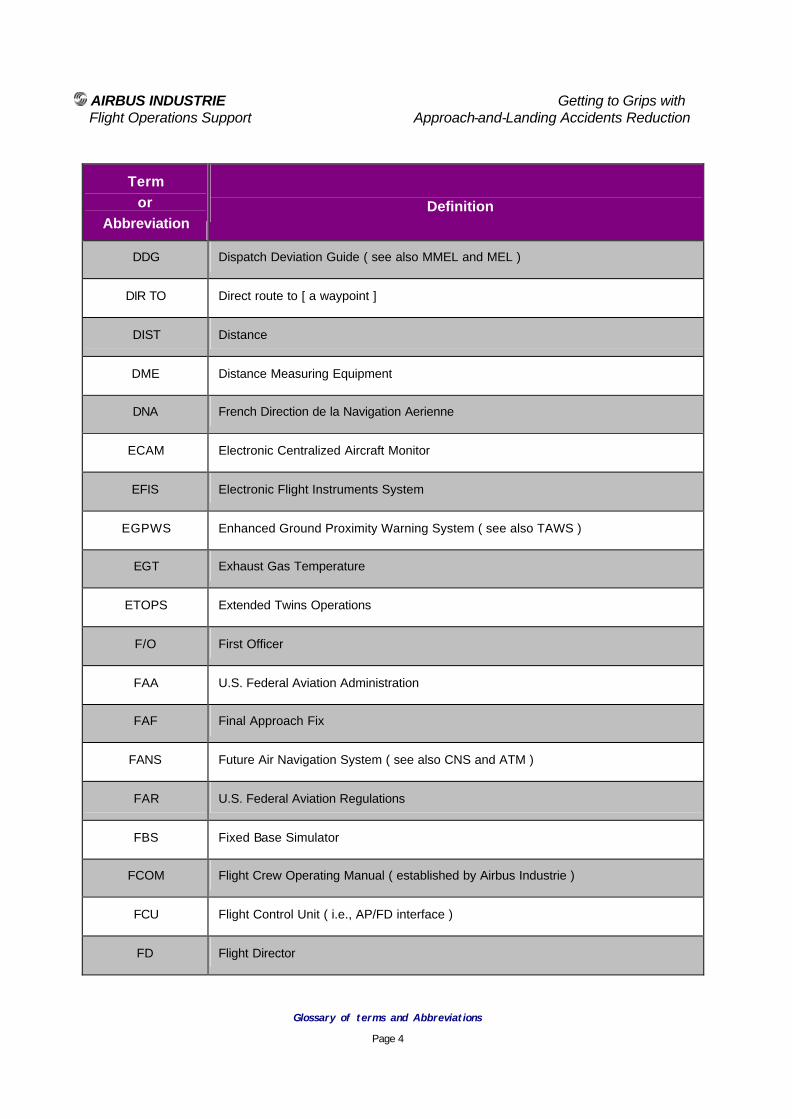
AIRBUS INDUSTRIE Getting to Grips with Flight Operations Support Approach-and-Landing Accidents Reduction
Glossary of terms and Abbreviations
Page 4
Term or
Abbreviation
Definition
DDG Dispatch Deviation Guide ( see also MMEL and MEL )
DIR TO Direct route to [ a waypoint ]
DIST Distance
DME Distance Measuring Equipment
DNA French Direction de la Navigation Aerienne
ECAM Electronic Centralized Aircraft Monitor
EFIS Electronic Flight Instruments System
EGPWS Enhanced Ground Proximity Warning System ( see also TAWS )
EGT Exhaust Gas Temperature
ETOPS Extended Twins Operations
F/O First Officer
FAA U.S. Federal Aviation Administration
FAF Final Approach Fix
FANS Future Air Navigation System ( see also CNS and ATM )
FAR U.S. Federal Aviation Regulations
FBS Fixed Base Simulator
FCOM Flight Crew Operating Manual ( established by Airbus Industrie )
FCU Flight Control Unit ( i.e., AP/FD interface )
FD Flight Director

AIRBUS INDUSTRIE Getting to Grips with Flight Operations Support Approach-and-Landing Accidents Reduction
Glossary of terms and Abbreviations
Page 5
Term or
Abbreviation
Definition
FDF Final Descent Fix
FFCC Forward-Facing-Crew Cockpit
FFS Full Flight Simulator
FIR Flight Information Region
FL Flight Level
FMGS Flight Management and Guidance System
FMA Flight Modes Annunciator
FMGES Flight Management, Guidance and [flight] Envelop [protection] System
FMS Flight Management System
FOQA Flight Operations Quality Assurance
FSF Flight Safety Foundation
ft Feet
GA Go Around
GAIN Global Analysis and Information Network
GCAS Ground Collision Avoidance System
GND Ground control frequency
GNSS Global Navigation Satellite System
GPS Global Positioning System
GPWS Ground Proximity Warning System
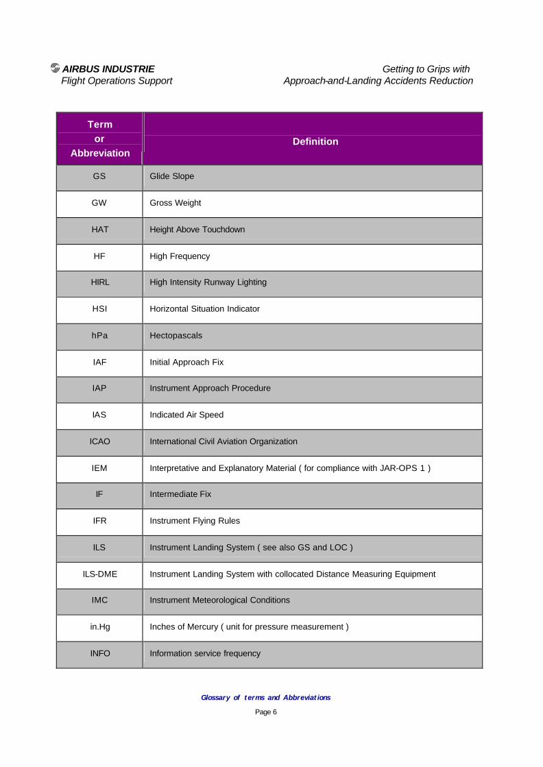
AIRBUS INDUSTRIE Getting to Grips with Flight Operations Support Approach-and-Landing Accidents Reduction
Glossary of terms and Abbreviations
Page 6
Term or
Abbreviation
Definition
GS Glide Slope
GW Gross Weight
HAT Height Above Touchdown
HF High Frequency
HIRL High Intensity Runway Lighting
HSI Horizontal Situation Indicator
hPa Hectopascals
IAF Initial Approach Fix
IAP Instrument Approach Procedure
IAS Indicated Air Speed
ICAO International Civil Aviation Organization
IEM Interpretative and Explanatory Material ( for compliance with JAR-OPS 1 )
IF Intermediate Fix
IFR Instrument Flying Rules
ILS Instrument Landing System ( see also GS and LOC )
ILS-DME Instrument Landing System with collocated Distance Measuring Equipment
IMC Instrument Meteorological Conditions
in.Hg Inches of Mercury ( unit for pressure measurement )
INFO Information service frequency

AIRBUS INDUSTRIE Getting to Grips with Flight Operations Support Approach-and-Landing Accidents Reduction
Glossary of terms and Abbreviations
Page 7
Term or
Abbreviation
Definition
IOE Initial Operating Experience ( Line Training )
IRS Inertial Reference System
JAA European Joint Aviation Authority
JAR European Joint Aviation Regulations
JAR-AWO JAR - All Weather Operations requirements
JAR-OPS JAR Operations requirements
JSAT U.S. CAST Joint Safety Analysis Team
JSIT U.S. CAST Joint Safety Implementation Team
JSSI European Joint Safety Strategies and Initiatives
kt Knots
LAAS GPS Local Area [accuracy] Augmentation System
LAHSHO Land and Hold Short operation
Lateral Navigation FMS managed lateral navigation ( i.e., NAV mode )
LDA LOC-type Directional Aid
LLWAS Low Level Windshear Alert System
LOC Localizer
LOC BCK CRS Localizer back course
LOFT Line Oriented Flight [simulator ] Training
m Meters

AIRBUS INDUSTRIE Getting to Grips with Flight Operations Support Approach-and-Landing Accidents Reduction
Glossary of terms and Abbreviations
Page 8
Term or
Abbreviation
Definition
MAP Missed Approach Point
MCDU Multi-purpose Control and Display Unit ( see also CDU )
MDA(H) Minimum Descent Altitude ( Height )
MEA Minimum Enroute Altitude
MEL Minimum Equipment List ( operator' customized version of MMEL )
METAR Meteorological Airport [observation] Report
MMEL Master Minimum Equipment List ( approved by operational authority )
Mode Type of guidance used to guide the aircraft towards a target or set of targets, or along a vertical flight path and/or lateral flight path
"Selected modes" refers to the modes armed or engaged by the pilot on the FCU
"Managed modes" refers to FMS vertical navigation and lateral navigation
MSA Minimum Safe Altitude or Minimum Sector Altitude
MSAW Minimum Safe Altitude Warning ( provided by ATC )
MSL Mean Sea Level ( e.g., 1000 ft - altitude above MSL, indicated by the barometric altimeter when set to QNH )
NATS U.K. National Air Traffic Services
Navaid Navigation Aid ( e.g., NDB, VOR, VOR-DME, LOC, ILS, ... )
ND Navigation Display
NDB Non Directional Beacon

AIRBUS INDUSTRIE Getting to Grips with Flight Operations Support Approach-and-Landing Accidents Reduction
Glossary of terms and Abbreviations
Page 9
Term or
Abbreviation
Definition
Next Target Any required element or combination of one or more of the following elements:
- A position,
- An altitude,
- An aircraft configuration,
- A speed,
- A vertical speed, and/or
- A power setting.
NEXT WPT The waypoint located after the TO WPT
nm Nautical miles
NOTAM NOtice To AirMen
OAT Outside Air Temperature
OCA(H) Obstacle Clearance Altitude ( Height )
OM Outer Marker
PA Passenger Address system
PAPI Precision Approach Path Indicator
PF Pilot Flying
PFD Primary Flight Display
PIC Pilot In Command
PIREPS Pilot REPorts

AIRBUS INDUSTRIE Getting to Grips with Flight Operations Support Approach-and-Landing Accidents Reduction
Glossary of terms and Abbreviations
Page 10
Term or
Abbreviation
Definition
PNF Pilot Not Flying
The PNF is sometimes referred to as the Pilot Monitoring to enhance his/her role in terms or monitoring, cross-check and backup
QAR Quick Access Recorder
QFE Actual atmospheric pressure at airport elevation
Altimeter setting required to read a height above airport elevation
QNH Actual atmospheric pressure at sea level, based on actual atmospheric pressure at station
Altimeter setting required to read an altitude above mean sea level ( MSL )
QRH Quick Reference Handbook
R/I Radio / Inertial navigation
RA Depending on context :
- Radio Altimeter, or
- Resolution Advisory ( see also TCAS )
RA DH Radio Altimeter Decision Height
Raw Data Raw navigation data : bearing and/or distance from aircraft to the tuned navaid
REIL Runway End Identification Lights
Reversion A mode reversion is a manual or automatic changeover from one AP mode to another mode ( usually, a lower level of automation ) resulting from:
- a pilot action ( e.g., the selection of a lower level of automation or the disengagement of a mode for manual reversion to the AP basic mode );
- a system built-in condition ( e.g., a guidance limit or an active flight envelope protection ); or,
- a failure or temporary loss of the engaged mode.

AIRBUS INDUSTRIE Getting to Grips with Flight Operations Support Approach-and-Landing Accidents Reduction
Glossary of terms and Abbreviations
Page 11
Term or
Abbreviation
Definition
RMI Radio Magnetic Indicator
RNAV aRea NAVigation ( i.e., lateral navigation based on defined waypoints )
RNP Required Navigation [accuracy] Performance
RVR Runway Visual Range
RVSM Reduced Vertical Separation Minima
SAT Static Air Temperature
SDF Simplified Directional Facility
SID Standard Instruments Departure
SOPs Standard Operating Procedures
Stabilization Height The height above airfield elevation or the height above touchdown ( HAT ) at which the aircraft should be stabilized for the approach to be continued
The stabilization height should be:
- 1000 ft in IMC; and,
- 500 ft in VMC
STAR Standard Terminal ARrival
STD Standard altimeter setting ( i.e., 1013.2 hPa or 29.92 in.hg )
TA Traffic Advisory ( see also TCAS )
Target A guidance target ( e.g., a speed, heading, altitude, vertical speed, flight path angle, track, course, etc ) selected by the pilot on the appropriate panel (FCU, FMS CDU or keyboard)
TAS True Air Speed

AIRBUS INDUSTRIE Getting to Grips with Flight Operations Support Approach-and-Landing Accidents Reduction
Glossary of terms and Abbreviations
Page 12
Term or
Abbreviation
Definition
TAWS Terrain Awareness and Warning System
TAWS is the term used by the European JAA and the U.S. FAA to describe equipment meeting ICAO standards and recommendations for ground-proximity warning system (GPWS) equipment that provides predictive terrain-hazard warnings
Enhanced-GPWS ( EGPWS ) and ground collision avoidance system ( ACAS ) are other terms used to describe TAWS equipment
TCAS Traffic Collision Avoidance System ( see also ACAS )
TDWR Terminal Doppler Weather Radar
Weather radar capable of detecting areas of wind shear activity
TDZ Touch Down Zone
TDZE Touch Down Zone Elevation
TERPS U.S. Standard for Terminal Instrument Approach Procedures ( FAR - Part 97 )
TO WPT Waypoint of the F-PLN flight plan considered by the FMS for immediate lateral navigation guidance ( in case of incorrect flight plan sequencing, the TO WPT may happen to be behind the aircraft )
TOD Top Of Descent
Transition A mode transition is a manual or automatic changeover from one AP mode to another mode, resulting from:
- a pilot action ( e.g., the selection of a new mode on the FCU, as appropriate for the task or following an ATC instruction ); or,
- an automatic mode sequencing resulting from a prior mode selection involving several mode changes in sequence ( e.g., altitude capture changeover to altitude hold or selected heading changeover to localizer capture then to localizer tracking )
V APP Final Approach Speed
V MCL Minimum control speed in landing configuration with the critical engine inoperative

AIRBUS INDUSTRIE Getting to Grips with Flight Operations Support Approach-and-Landing Accidents Reduction
Glossary of terms and Abbreviations
Page 13
Term or
Abbreviation
Definition
V REF Reference approach speed ( also referred to as threshold reference speed or target threshold speed )
V stall Stalling speed ( in a specified configuration )
V/S Vertical speed or AP Vertical Speed mode
VASI Visual Approach Indicator
VDP Visual Descent / Decision Point
Vertical Navigation FMS-managed vertical navigation
VFR Visual Flying Rules
VHF Very High Frequency
VMC Visual Meteorological Conditions
VOR VHF Omni Range
VOR-DME Collocated VOR and DME navaids
WAAS GPS Wide Area [accuracy] Augmentation System
WMO World Meteorological Organization

AIRBUS INDUSTRIE Getting to Grips with Flight Operations Support Approach-and-Landing Accidents Reduction
Chapter 1
Operating Philosophy - SOPs

AIRBUS INDUSTRIE Getting to Grips with
Flight Operations Support Approach-and-Landing Accidents Reduction
Standard Operating Procedures
Page 1
Approach-and-Landing Briefing Note
1.1 – Operating Philosophy - SOPs
Introduction Strict adherence to suitable standard operating procedures (SOPs) and normal checklists is an effective method to prevent approach-and-landing accidents, including those involving CFIT. Without strict adherence to SOPs, the implementation of good crew resources management (CRM) practices is not possible. This Briefing Note provides an overview of the following aspects:
• Establishment and use of (SOPs);
• Training aspects; and,
• Factors and conditions that may affect the compliance with published rules and procedures.
Statistical Data
Factor % of
Events
Omission of action or inappropriate action
72 %
Non-adherence to criteria for stabilized approach
66 %
Inadequate crew coordination, cross-check and back-up
63 %
Insufficient horizontal or vertical situational awareness
52 %
Inadequate or insufficient understanding of prevailing conditions
48 %
Slow or delayed action 45 %
Deliberate non-adherence to procedures
40 %
Incorrect or incomplete pilot / controller communications
33 %
Interaction with automation 20 %
Absence of go-around when required
17 %
Table 1
Causal Factors related to SOPs in Approach-and-Landing Accidents

AIRBUS INDUSTRIE Getting to Grips with
Flight Operations Support Approach-and-Landing Accidents Reduction
Standard Operating Procedures
Page 2
Airbus Industrie’ SOPs Standard Operating Procedures (SOPs) published by Airbus Industrie are designed to achieve the following objectives:
• Reflect the Airbus Industrie’ cockpit design philosophy and operating philosophy;
• Promote optimum use of aircraft-type design features; and,
• Apply to a broad range of airline operations and environments.
The initial SOPs for a new aircraft model are based on the above objectives and on the experience gained during the development and certification flight-test campaign and during the route-proving program. After they are introduced into service, the initial SOPs are periodically reviewed and enhanced based on the feedback received from various users (i.e., in training and in line operations). Operator’ Customized SOPs Airbus Industrie’ SOPs can be adopted without change by an operator or used as the basis for the development of customized company’ SOPs. Customized company SOPs usually are established to assure standardization across the different aircraft fleets being operated by the airline. Deviations from the Airbus Industrie’ SOPs may be coordinated with Airbus Industrie, such deviations usually require approval by the airline’s operational authority. SOPs should be simple, clear, concise and directive; the level of expanded information should be tailored to reflect the airline’s operating philosophy and training philosophy. Operator’s SOPs should be reviewed and reassessed periodically based on revisions of the Airbus Industrie’s SOPs and on internal company feedback, to identify any need for change.
Line pilots and cabin crewmembers should be involved, along with the flight standards team, in the development and revision process of company SOPs to:
• Promote critical and constructive feedback; and,
• Ensure that rules and procedures, as well as reasons for their adoption are fully understood by end users.
Scope of SOPs SOPs should identify and describe the standard tasks and duties of flight -crew for each flight phase. SOPs should be accomplished by recall but critical tasks (e.g., selections of systems and changes of aircraft configuration) should be cross-checked by use of normal checklists, according to the phase of flight. SOPs should be supplemented by information on specific operating techniques (e.g., adverse weather operation) or by operational recommendations for specific types of operations (e.g., operation on wet or contaminated runway, operation in ETOPS area and/or in RVSM airspace). SOPs should assume that all aircraft systems operate normally and that all automatic functions are used normally.
Note : A system may be partially or totally inoperative without affecting the SOPs.
SOPs should emphasize the following aspects frequently involved in approach-and-landing accidents:
• Task sharing;
• Optimum use of automation;
• Operations Golden Rules;
• Standards calls;
AIRBUS INDUSTRIE Getting to Grips with
Flight Operations Support Approach-and-Landing Accidents Reduction
Standard Operating Procedures
Page 3
• Use of normal checklists;
• Approach and go-around briefings;
• Altimeter setting and cross-check procedures;
• Descent profile management;
• Energy management;
• Terrain awareness;
• Approach hazards awareness;
• Use of radio altimeter;
• Elements of a stabilized approach and approach gates;
• Approach procedures and techniques for various types of approaches;
• Landing and braking techniques for various types of runway and wind conditions; and,
• Readiness and commitment to go-around (e.g., GPWS warning, unstabilized approach, bounce recovery).
In addition, SOPs should address the following aspects: Regulatory Definition The U.S. FAA defines the scope and contents of SOPs in Advisory Circular (AC) 120-71. The SOPs defined in AC 120-71 includes items related to:
• General operations policies (i.e., non-type related); and,
• Airplane operating matters (i.e., type-related)
The European JAA defines the scope and contents of SOPs in JAR-OPS 1.1045 and associated Appendix 1. The scope of SOPs defined in the FAA AC 120-71 is allocated by the JAA to the Part A and Part B of the Operations Manual, as follows:
• Part A : General operational policies (i.e., non-type-related matters); and,
• Part B : Aeroplane operating matters (i.e., type-related matters).
General Principles SOPs should contain safeguards in order to minimize the potential for inadvertent deviation from procedures, particularly when operating under abnormal or emergency conditions or following interruptions or distractions. Safeguards include:
• Triggers:
− events or actions initiating groups of actions (called action-blocks);
• Action blocks:
− groups of actions being accomplished in sequence as a group;
• Action patterns:
− flightdeck panel scanning sequences or patterns supporting the flow and sequence of action blocks; and,
• Standard calls:
− standard phraseology and terms used for effective intra-crew communication.
Standardization SOPs (including standard calls) constitute the reference for crew standardization and provide the working environment required for enhanced and efficient crew communication and coordination.

AIRBUS INDUSTRIE Getting to Grips with
Flight Operations Support Approach-and-Landing Accidents Reduction
Standard Operating Procedures
Page 4
Task Sharing The following rules apply to any flight phase but are particularly important in the high-workload phases associated with approach and landing. The pilot flying (PF) is responsible for controlling the vertical flight path and horizontal flight path and for energy management, by either:
• Supervising the autopilot vertical guidance and lateral guidance and the autothrust operation (i.e., awareness of modes being armed or engaged, and of mode changes through mode transitions and reversions);
or,
• Hand flying the aircraft, with or without flight director (FD) guidance, and with an adapted navigation display (e.g., ROSE or ARC mode).
The pilot not flying (PNF) is responsible for monitoring tasks and for performing the actions requested by the PF; this includes:
• Performing the standard PNF tasks:
− SOP actions; and,
− Flight director and FMS mode selections and target entries, when in manual flight;
• Monitoring the current status of the aircraft; and,
• Monitoring the PF to provide effective backup as required (this includes both flight and ground operation).
Sterile Cockpit Rule Adhering to the Sterile Cockpit rule (defined in Briefing Note 2.4 – Intra-Cockpit Communications, Managing Interruptions and Distractions ) may be mandated by operational authorities (e.g., U.S. FAR – Part 121.542 ) or adopted per company policy. Airbus Industrie encourages adherence to the Sterile Cockpit rule, regardless of applicable national requirements.
Silent Cockpit The Sterile Cockpit rule and the Silent Cockpit concept often are misunderstood as referring to the same operating policy. When adhering to a Silent Cockpit policy, standard calls are minimized; FCU selections, FMA changes and target confirmations on PFD and ND are not announced loudly but included in the instruments scan. Airbus Industrie acknowledges that variations may exist in airline operating policies but encourages operators to adopt and adhere to a Standard Calls policy, as defined in Briefing Note 1.4 – Standard Calls. Use of Automation With higher levels of automation, flight crews are offered an increasing number of options and strategies to choose for the task to be accomplished. The company SOPs should accurately define the options and strategies selected by the airline for the various flight phases and for the various types of approaches. Briefing Note 1.2 - Optimum Use of Automation provides expanded information on the use of AP/FD, A/THR and FMS. Scope and Use of Normal Checklists Briefing Note 1.5 - Normal Checklists provides a detailed overview on the scope and use of normal checklists. Training Aspects Disciplined use of SOPs and normal checklists should begin during the transition training course, because habits and routines acquired during transition training have a lasting effect.
AIRBUS INDUSTRIE Getting to Grips with
Flight Operations Support Approach-and-Landing Accidents Reduction
Standard Operating Procedures
Page 5
Transition training and recurrent training provide a unique opportunity to discuss the reasons for the rules and procedures and to discuss the consequences of failing to comply with them. Conversely, allowing a relaxed adherence to SOPs and/or a relaxed use of normal checklists during initial or recurrent simulator training may encourage corresponding deviations during line operations. Factors Involved in Deviations from SOPs To ensure effective compliance with published SOPs, it is important to understand why pilots intentionally or inadvertently deviate from rules or standards. In most cases of deviation from SOPs, the procedure that was followed in place of the published procedure seemed to be appropriate for the prevailing situation, considering the information available at the time. The following factors and conditions are cited often in discussing deviations from SOPs:
• Inadequate knowledge of or failure to understand the rule, procedure or action (e.g., due to quality of wording or phrasing, rule or procedure or action being perceived as inappropriate);
• Insufficient emphasis on strict adherence to SOPs during transition and recurrent training;
• Insufficient vigilance (fatigue);
• Distractions (e.g., due to intra-cockpit activity);
• Interruptions (e.g., due to ATC communication);
• Task saturation (i.e., absence of multi-tasking ability or task overload);
• Incorrect management of priorities (e.g., lack of decision-making model for time-critical situations);
• Reduced attention ( tunnel vision ) in abnormal or high-workload conditions;
• Incorrect CRM techniques (e.g., absence of cross-checking, crew coordination or effective backup);
• Company policies (e.g., regarding schedules, costs, go-around and diversion);
• Other policies (e.g., crew duty time);
• Personal desires or constraints (e.g., schedule, mission completion);
• Complacency; and,
• Overconfidence (e.g., high time on aircraft type).
These factors may be used to assess company and/or personal exposure, and to develop corresponding prevention strategies and lines -of-defense. Summary of Key Points SOPs should include and emphasize aspects that are involved frequently in approach-and-landing accidents. Company policies, technical training and CRM training programs, line checks and line audits should:
• Promote strict adherence to SOPs; and,
• Identify and address the reasons for intentional or inadvertent deviations from SOPs.
Associated Briefing Notes The following Briefing Notes should be reviewed along with the above general information in order to revisit all the aspects associated with standard operating procedures:
• 1.2 - Optimum Use of Automation,
• 1.3 - Operations Golden Rules,
• 1.4 - Standard Calls,
• 1.5 - Use of Normal Checklists,

AIRBUS INDUSTRIE Getting to Grips with
Flight Operations Support Approach-and-Landing Accidents Reduction
Standard Operating Procedures
Page 6
• 1.6 - Approach and Go-around Briefings,
• 2.1 - HF Issues in Approach and Landing Accidents,
• 2.2 - CRM Issues in Approach and Landing Accidents.
Regulatory References
• ICAO – Annex 6 – Operation of Aircraft, Part I – International Commercial Air transport – Aeroplanes, Appendix 2, 5.9.
• ICAO – Procedures for Air Navigation Services – Aircraft Operations (PANS-OPS, Doc 8168), Volume I – Flight procedures (Post Amendment No 11, applicable Nov.1/2001).
• ICAO – Manual of All-Weather Operations (Doc 9365).
• ICAO – Preparation of an Operations Manual (Doc 9376).
• FAR 91.3 – Responsibility and authority of the pilot-in-command (emergency authority).
• FAR 121.133 – Preparation of Manuals,
• FAR 121.135 – Contents of Manuals,
• FAA AC 120-71 - Standard Operating Procedures for Flightdeck Crew Members (Draft).
• FAA AC 120-48 – Communications and Coordination between Flight Crewmembers and Flight Attendants.
• FAA AC 120-51 – Crew Resource Management Training.
• FAA AC 120-54 – Advance Qualification Training.
• FAA AC 120-71 – Standard Operating Procedures for Flight Deck Crewmembers.
• FAA AC 121-32 – Dispatch Resource Management Training.
• JAR-OPS 1.1040 and associated Interpretative and Explanatory Material (IEM) – General Rules for Operations Manuals.
• JAR-OPS 1.1045 and associated Appendix 1, Acceptable Means of Compliance (AMC) and Interpretative and Explanatory Material (IEM) – Operations Manual – structure and contents.

AIRBUS INDUSTRIE Getting to Grips with Flight Operations Support Approach-and-Landing Accidents Reduction
Optimum Use of Automation
Page 1
Approach-and-Landing Briefing Note
1.2 - Optimum Use of Automation
Introduction Optimum use of automation refers to the integrated and coordinated use of the following systems:
• Autopilot / flight director (AP / FD);
• Autothrottle/autothrust (A/THR); and,
• Flight management system (FMS).
Three generations of flight guidance systems are currently in airline service, providing different levels of integration and automation:
• A300B2/B4 and A300 FFCC families:
− Partial integration (pairing) of the AP/FD and A/THR modes;
− Selected vertical and lateral modes; and,
− Lateral navigation only (i.e., inertial navigation system [INS] or FMS/GPS).
• A310 and A300-600 families:
− Full integration of AP/FD and A/THR modes;
− Selected vertical and lateral modes; and,
− Vertical and lateral navigation (FMS),
• A320 / A330 / A340 families:
− Full integration of AP/FD - A/THR – FMS modes (FMGS);
− Selected vertical and lateral modes; and,
− Managed vertical and lateral navigation in all flight phases.
Higher levels of automation provide flight crews with an increasing number of options and strategies to choose for the task to be accomplished. The applicable FCOM provides specific information for each aircraft type. Statistical Data Errors in using and managing the automatic flight system and the lack of awareness of the operating modes are causal factors in more than 20 % of approach-and-landing accidents. AP - A/THR Integration Integrated AP-A/THR systems feature an association (pairing) of AP pitch modes (elevator control) and A/THR modes (throttle/thrust levers control). An integrated AP-A/THR operates in the same way as a human pilot:
• Elevator is used to control pitch attitude, airspeed, vertical speed, altitude, flight-path-angle, vertical navigation profile or to track a glideslope beam;
• Throttle/thrust levers are used to maintain a given thrust or a given airspeed.
Throughout the flight, the pilot’s objective is to fly:
• Performance segments at constant thrust or at idle (e.g., takeoff, climb or descent); or,
• Trajectory segments at constant speed (e.g., cruise or approach).
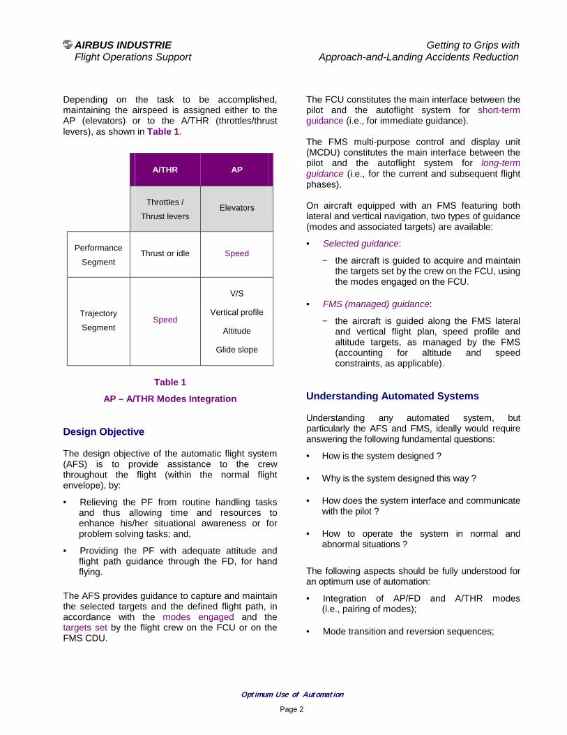
AIRBUS INDUSTRIE Getting to Grips with Flight Operations Support Approach-and-Landing Accidents Reduction
Optimum Use of Automation
Page 2
Depending on the task to be accomplished, maintaining the airspeed is assigned either to the AP (elevators) or to the A/THR (throttles/thrust levers), as shown in Table 1.
A/THR AP
Throttles /
Thrust levers Elevators
Performance
Segment Thrust or idle Speed
Trajectory
Segment
Speed
V/S
Vertical profile
Altitude
Glide slope
Table 1
AP – A/THR Modes Integration Design Objective The design objective of the automatic flight system (AFS) is to provide assistance to the crew throughout the flight (within the normal flight envelope), by:
• Relieving the PF from routine handling tasks and thus allowing time and resources to enhance his/her situational awareness or for problem solving tasks; and,
• Providing the PF with adequate attitude and flight path guidance through the FD, for hand flying.
The AFS provides guidance to capture and maintain the selected targets and the defined flight path, in accordance with the modes engaged and the targets set by the flight crew on the FCU or on the FMS CDU.
The FCU constitutes the main interface between the pilot and the autoflight system for short-term guidance (i.e., for immediate guidance). The FMS multi-purpose control and display unit (MCDU) constitutes the main interface between the pilot and the autoflight system for long-term guidance (i.e., for the current and subsequent flight phases). On aircraft equipped with an FMS featuring both lateral and vertical navigation, two types of guidance (modes and associated targets) are available:
• Selected guidance:
− the aircraft is guided to acquire and maintain the targets set by the crew on the FCU, using the modes engaged on the FCU.
• FMS (managed) guidance:
− the aircraft is guided along the FMS lateral and vertical flight plan, speed profile and altitude targets, as managed by the FMS (accounting for altitude and speed constraints, as applicable).
Understanding Automated Systems Understanding any automated system, but particularly the AFS and FMS, ideally would require answering the following fundamental questions:
• How is the system designed ?
• Why is the system designed this way ?
• How does the system interface and communicate with the pilot ?
• How to operate the system in normal and abnormal situations ?
The following aspects should be fully understood for an optimum use of automation:
• Integration of AP/FD and A/THR modes (i.e., pairing of modes);
• Mode transition and reversion sequences;

AIRBUS INDUSTRIE Getting to Grips with Flight Operations Support Approach-and-Landing Accidents Reduction
Optimum Use of Automation
Page 3
• Pilot-system interfaces for:
− Pilot-to-system communication (i.e., for modes engagement and target selections); and,
− System-to-pilot feedback (i.e., for modes and targets cross-check).
In the context of this Briefing Note, the interface and communication between the flight crew and the system need to be emphasised. Flight Crew / System Interface When performing an action on the FCU or FMS CDU to give a command to the AFS, the pilot has an expectation of the aircraft reaction and, therefore, must have in mind the following questions:
• What do I want the aircraft to fly now ?
• What do I want to fly next ?
This implies answering also the following questions :
• Which mode did I engage and which target did I set for the aircraft to fly now ?
• Is the aircraft following the intended vertical and lateral flight path and targets ?
• Which mode did I arm and which target did I pre set for the aircraft to fly next ?
The key role of the following controls and displays therefore must be understood:
• FCU mode selection-keys, target-setting knobs and display windows;
• FMS MCDU keyboard, line-select keys, display pages and messages;
• Flight modes annunciator (FMA) annunciations on PFD; and,
• PFD and ND data.
Effective monitoring of these controls and displays promotes and increases flight crew awareness of:
• The status of the system (i.e., modes being engaged or armed); and,
• The available guidance (i.e., for flight path and speed control).
Effective monitoring of controls and displays also enables the pilot to predict and anticipate the entire sequence of flight modes annunciations (FMA) throughout flight phases (i.e., throughout mode transitions or mode reversions). Operating Philosophy and Rules Optimum use of automation requires strict adherence to the design philosophy and operating philosophy, and to the following rules of operation.
Use the correct level of automation for the task On highly automated and integrated aircraft, several levels of automation are available to perform a given task:
• FMS modes and guidance; or,
• Selected modes and guidance.
The correct level of automation depends on:
• The task to be performed:
− short-term (tactical) task; or,
− long-term (strategic) task;
• The flight phase:
− enroute;
− terminal area; or,
− approach; and,
• The time available:
− normal selection or entry; or,
− last-minute change.
AIRBUS INDUSTRIE Getting to Grips with Flight Operations Support Approach-and-Landing Accidents Reduction
Optimum Use of Automation
Page 4
The correct level of automation often is the one the pilot feels comfortable with for the task or for the prevailing conditions, depending on his/her knowledge and experience of the aircraft and systems.
Reversion to hand flying and manual thrust control actually may be the correct level of automation, depending on the prevailing conditions. FMS or selected guidance can be used in succession or in combination (e.g., FMS lateral guidance together with selected vertical guidance) as best suited for the flight phase and prevailing constraints. The PF always retain the authority and capability to select the most appropriate level of automation and guidance for the task, this includes:
• Adopting a more direct level of automation by reverting from FMS-managed guidance to selected guidance (i.e., to selected modes and targets);
• Selecting a more appropriate lateral or vertical mode; or,
• Reverting to hand flying (with or without FD guidance, with or without A/THR) for direct control of aircraft vertical trajectory, lateral trajectory and thrust.
Know your Available Guidance at all times The FCU and the FMS CDU are the prime interfaces for the flight crew to communicate with the aircraft systems (i.e., to arm or engage modes and to set targets). The PFD and ND are the prime interfaces for the aircraft to communicate with the flight crew, to confirm that the aircraft systems have correctly accepted the mode selections and target entries:
• PFD (FMA, speed scale and altitude scale):
− guidance modes, speed and altitude targets; and,
• ND :
− lateral guidance ( heading or track or FMS flight plan).
Any action on the FCU or on the FMS keyboard and line-select keys should be confirmed by cross-checking the corresponding annunciation or data on the PFD and/or ND (and on the FMS CDU). At all times, the PF and PNF should be aware of the status of the guidance modes being armed or engaged and of any mode change-over throughout mode transitions and reversions. Enhanced reference to the above controls and displays promotes and increases the flight crew awareness of :
• The status of the system (i.e., modes being armed or engaged),
• The available guidance (i.e., for flight path and speed control).
This enables the flight crew to predict and anticipate the entire sequence of flight mode annunciations throughout successive flight phases (i.e., throughout mode transitions or reversions). Monitor automation at all times The use and operation of the AFS must be monitored at all times by:
• Checking and announcing the status of AP/FD modes and A/THR mode on the FMA (i.e., arming or engagement);
• Observing and announcing the result of any target setting or change (on the FCU) on the related PFD and/or ND scales; and,
• Supervising the resulting AP/FD guidance and A/THR operation on the PFD and ND (pitch attitude and bank angle, speed and speed trend, altitude, vertical speed, heading or track, …).
Be ready to take over, if required If doubt exists regarding the aircraft flight path or speed control, no attempt at reprogramming the automated systems should be made. Selected guidance or hand flying together with the use of navaids raw data should be used until time and conditions permit reprogramming the AP/FD or FMS.

AIRBUS INDUSTRIE Getting to Grips with Flight Operations Support Approach-and-Landing Accidents Reduction
Optimum Use of Automation
Page 5
If the aircraft does not follow the intended flight path, check the AP and A/THR engagement status. If engaged, disconnect the AP and/or A/THR using the associated instinctive disconnect push button(s), to revert to hand flying (with FD guidance or with reference to raw data) and/or to manual thrust control. In hand flying, the FD commands should be followed; otherwise the FD bars should be cleared from display. AP and A/THR must not be overridden manually. If AP or A/THR operation needs to be overridden (i.e., following a runaway or hardover), immediately disconnect the affected system by pressing the associated instinctive disconnect push button. Factors and Errors in Using Automation The following factors and errors can cause flying an incorrect flight path, which - if not recognized - can lead to an approach-and-landing accident, including one involving CFIT:
• Inadvertent arming or engagement of an incorrect mode;
• Failure to verify the mode armed or engaged, by reference to the FMA ;
• Selection of an incorrect target (altitude, speed, heading) on the FCU and failure to confirm the selected target on the PFD and/or ND (as applicable);
• Selection of the FCU altitude to any altitude below the final approach intercept altitude during approach;
• Insertion of an erroneous waypoint;
• Arming of the lateral navigation mode with an incorrect active waypoint (i.e., an incorrect TO waypoint);
• Preoccupation with FMS programming during a critical flight phase, with consequent loss of situational awareness;
• Insufficient understanding of mode transitions and mode reversions (i.e., mode confusion);
• Inadequate task sharing and/or CRM practices preventing the PF from monitoring the flight path and airspeed;
(e.g., both pilots being engaged in the management of automation or in solving an unanticipated situation or abnormal condition);
• Engaging the AP with the aircraft in an out-of-trim condition (conventional aircraft only);
• Failure to arm the approach mode; and/or,
• Failure to set the correct final approach course. Recommendations for Optimum Use of Automation Correct use of automated systems reduces workload and significantly improves the flight crew time and resources for responding to:
• An unanticipated change; or,
• An abnormal or emergency condition.
During line operations, AP and A/THR should be engaged throughout the flight especially in marginal weather conditions or when operating into an unfamiliar airport. Using AP and A/THR also enables flight crew to pay more attention to ATC communications and to other aircraft, particularly in congested terminal areas and at high-density airports. AP and A/THR should be used during a go-around and missed-approach to reduce workload. FMS lateral navigation should be used to reduce workload and risk of CFIT during go-around if :
• Applicable missed-approach procedure is included in the FMS flight plan; and,
• FMS navigation accuracy has been confirmed.
AIRBUS INDUSTRIE Getting to Grips with Flight Operations Support Approach-and-Landing Accidents Reduction
Optimum Use of Automation
Page 6
The safe and efficient use and management of AP, A/THR and FMS are based on the following three-step technique:
• Anticipate:
− Understand system operation and results of any action, be aware of modes being armed or engaged (seek concurrence of other crewmember, if deemed necessary);
• Execute:
− Perform action on FCU or on FMS CDU; and,
• Confirm:
− Crosscheck and announce arming or engagement of modes and targets selections (on FMA, PFD and/or ND scales or FMS CDU).
The following rules and recommendations should be considered to support the implementation of this technique:
• Before engaging the AP, make sure that:
− Modes engaged for FD guidance (check FMA annunciations) are the correct modes for the intended flight phase and task;
Select the appropriate mode(s), as required; and,
− Command bars do not shows large orders; if large commands are given, maintain hand flying to center the bars before engaging AP;
Engaging the AP while large commands are required to achieve the intended flight path may result in the AP overshooting the intended vertical target or lateral target;
• Before any action on FCU, check that the knob or push button is the correct one for the desired function;
• After each action on FCU, verify the result of this action on:
− FMA (i.e., for arming or engagement of modes); and/or,
− PFD/ND data (i.e., for selected targets); and,
by reference to the aircraft flight path and airspeed response;
• Announce all changes in accordance with Standard Calls defined in SOPs;
• When changing the selected altitude on FCU, cross-check the selected altitude indication on PFD;
During descent, ensure that selected altitude is not to below the MEA or MSA (or be aware of the applicable minimum-vectoring-altitude);
During final approach, set go-around altitude on FCU (i.e., the MDA/H or DA/H should not be set);
• Prepare FMS for arrival before starting the descent;
An alternative arrival routing, another runway or circling approach, can be prepared on the secondary flight plan, as anticipated;
• In case of a routing change (e.g., DIR TO), cross-check the new TO waypoint before activating the DIR TO (i.e., making sure that the intended TO waypoint is not already behind the aircraft);
Caution is essential during descent in mountainous areas; ensure that the new track and assigned altitude are not below the sector safe altitude;
If under radar vectors, be aware of the sector minimum vectoring-altitude;
If necessary, the selected heading mode can be used with reference to navaids raw data, while verifying the new route and/or requesting confirmation from ATC;
• Before arming the NAV mode, ensure that the correct active waypoint (i.e., TO waypoint) is displayed on the FMS CDU and ND (as applicable);
If the displayed TO waypoint on the ND is not correct, the desired TO waypoint can be restored by either:
− clearing an undue intermediate waypoint; or,
− performing a DIR TO [desired TO waypoint].
Monitor the correct interception of the FMS lateral flight plan;

AIRBUS INDUSTRIE Getting to Grips with Flight Operations Support Approach-and-Landing Accidents Reduction
Optimum Use of Automation
Page 7
• In case of a late routing or runway change, a reversion to AP selected modes and raw data is recommended;
Reprogramming the FMS during a critical flight phase (e.g., in terminal area, on final approach or go-around) is not recommended, except to activate the secondary flight plan, if prepared, or for selecting a new approach; Priority tasks are, in that order :
− horizontal and vertical flight path control;
− altitude and traffic awareness; and,
− ATC communications;
• No attempt should be made to analyze or rectify an anomaly by reprogramming the AFS or FMS, until the desired flight path and/or airspeed are restored;
• In case of AP uncommanded disconnection, the second AP should be engaged immediately to reduce PF’s workload (i.e., only dual or multiple failures may affect both APs simultaneously);
• If cleared to exit a holding pattern on a radar vector, the holding exit prompt should be pressed (or the holding pattern cleared) to allow the correct sequencing of the FMS flight plan;
• Under radar vectors, when intercepting the final approach course in a selected heading or track mode (i.e., not in NAV mode), flight crew should ensure that FMS flight plan sequences normally by checking that the TO waypoint is correct (on ND and FMS CDU);
Ensuring that FMS flight plan sequences correctly with a correct TO waypoint is essential to re-engage the NAV mode, in case of a go-around;
If FMS flight plan does not sequence correctly, correct sequencing can be restore by either:
− performing a DIR TO [ a waypoint ahead in the approach ] or a DIR TO INTCPT (as available); or,
− clearing an undue intermediate waypoint (be cautious not to clear the desired TO waypoint).
If a correct TO waypoint cannot be restored, the NAV mode should not be used for the rest of the approach or for go-around;
• At any time, if the aircraft does not follow the desired flight path and/or airspeed, do not hesitate to revert to a more direct level of automation:
− revert from FMS-managed modes to selected modes;
or,
− disconnect AP and follow FD guidance (if correct);
or,
− disengage FD, select FPV (as available) and hand fly the aircraft, using raw data or visually (if in VMC);
and/or,
− disengage the A/THR and control the thrust manually.
Summary of key points For optimum use of automation, the following should be promoted:
• Understanding the integration of AP/FD and A/THR modes (i.e., pairing of modes);
• Understanding all mode transition and reversion sequences;
• Understanding pilot-system interfaces for:
− Pilot-to-system communication (i.e., for modes engagement and target selections);
− System-to-pilot feedback (i.e., for modes and targets cross-check);
• Awareness of available guidance (AP/FD and A/THR status, modes armed or engaged, active targets);
• Alertness to adapt the level of automation to the task and/or circumstances, or to revert to hand flying / manual thrust control, if required;
• Adherence to design philosophy and operating philosophy, SOPs and Operations Golden Rules.

AIRBUS INDUSTRIE Getting to Grips with Flight Operations Support Approach-and-Landing Accidents Reduction
Optimum Use of Automation
Page 8
Associated Briefing Notes The following Briefing Notes should be reviewed along with the above information to complement this overview on the use of automation:
• 1.1 - Operating Philosophy - SOPs,
• 1.3 - Operations Golden Rules,
• 1.4 - Standard Calls. Regulatory references
• ICAO – Annex 6 Operation of Aircraft, part I – International Commercial transport – Aeroplanes, Appendix 2, 5.14.
• ICAO – Human Factors Training Manual (Doc 9683).
• ICAO – Human Factors Digest No 5 – Operational Implications of Automation in Advanced Technology Flight Decks (Circular 234).
• FAR 121-579 - Minimum altitudes for the use of the autopilot.

AIRBUS INDUSTRIE Getting to Grips with
Flight Operations Support Approach-and-Landing Accidents Reduction
Operations Golden Rules
Page 1
Approach-and-Landing Briefing Note
1.3 - Operations Golden Rules
Introduction Golden Rules have always guided human activities. In early aviation days, the Golden Rules defined the basic principles of airmanship. With the development of technology in modern aircraft and with research on man-machine-interface and crew-coordination, Golden Rules have been broadened to encompass the principles of interaction with automation and crew resources management (CRM). The operations Golden Rules defined by Airbus Industrie assist trainees in maintaining their basic airmanship even as they progress to integrated and automated aircraft models. These rules apply with little modification to all Airbus models. Although developed for trainees, the Golden Rules are equally useful for experienced line pilots. Golden Rules address aspects that are considered frequent causal factors in approach and landing accidents:
• Inadequate situational / positional awareness;
• Incorrect interaction with automation;
• Overreliance on automation; and,
• Ineffective crew cross-check and mutual backup.
Statistical Data The following factors frequently are identified as causal factor in approach-and-landing accidents:
Factor % of Events
Inadequate decision making 74 %
Omission of action or inappropriate action
72 %
Inadequate CRM practice (crew coordination, cross-check and backup)
63 %
Insufficient horizontal or vertical situational awareness
52 %
Inadequate or insufficient understanding of prevailing conditions
48 %
Slow or delayed crew action 45 %
Flight handling difficulties 45 %
Incorrect or incomplete pilot/controller communication
33 %
Interaction with automation 20 %
Table 1
Most Frequent Causal Factors
in Approach-and-Landing Accidents

AIRBUS INDUSTRIE Getting to Grips with
Flight Operations Support Approach-and-Landing Accidents Reduction
Operations Golden Rules
Page 2
General Golden Rules The following eight Golden Rules are applicable in normal conditions and, more importantly, in any unanticipated or abnormal / emergency condition.
Automated aircraft can be flown like any other aircraft. To promote this rule, each trainee should be given the opportunity to fly the aircraft just using the stick, rudder and throttles. The use of flight director (FD), autopilot (AP), autothrottle/autothrust (A/THR) and flight management system (FMS) should be introduced progressively, as defined by the applicable training syllabus. Practice of hand flying will illustrate that the pilot flying (PF) always retains the authority and capability to adopt:
• A more direct level of automation; or revert to,
• Hand flying, directly controlling the aircraft trajectory and energy.
Fly, Navigate, Communicate and Manage – in that order Task sharing should be adapted to the prevailing situation (i.e., task sharing for hand flying or with AP engaged, task sharing for normal operation or for abnormal / emergency conditions, as defined in FCOM) and tasks should be accomplished in accordance with the following priorities: • Fly :
PF must concentrate on flying the aircraft (i.e., by controlling and/or monitoring the pitch attitude, bank angle, airspeed, thrust, sideslip, heading, ...) to capture and maintain the desired targets, vertical flight path and lateral flight path.
PNF must backup the PF by monitoring flight parameters and by calling any excessive deviation.
• Navigate :
Select the desired modes for vertical navigation and lateral navigation (i.e., selected modes or FMS-managed navigation), being aware of surrounding terrain and minimum safe altitude. This rule can be summarized by the following three “ know where …” situational-awareness items:
− Know where you are;
− Know where you should be; and,
− Know where the terrain and obstacles are.
• Communicate :
Effective crew communication involves communications between flight crewmembers and communications between flight crew and cabin crew. In an abnormal or emergency condition, after a stable flight path has been regained and the abnormal or emergency condition has been identified, the PF should inform the ATC of the prevailing condition and of his/her intentions. To attract the controller’s attention, use the following standard phraseology, as applicable:
− Pan Pan – Pan Pan – Pan Pan; or
− Mayday – Mayday – Mayday.
• Manage :
Managing the continuation of the flight is the next priority, this includes:
• Managing aircraft systems (e.g., fuel management, ETOPS management, etc); and,
• Performing applicable emergency and/or abnormal procedure(s).
Specific Golden Rules to assist flight crew in their decision-making and management process are provided in the second part of this Briefing Note.

AIRBUS INDUSTRIE Getting to Grips with
Flight Operations Support Approach-and-Landing Accidents Reduction
Operations Golden Rules
Page 3
The design of glass-cockpit aircraft fully supports the above four-step strategy, as summarized in Table 1.
Golden Rule Display Unit
Fly PFD
Navigate ND
Communicate DCDU
Manage ECAM
Table 1
Glass-cockpit Design Supports Golden Rules Practice task sharing and back-up each other Task sharing, effective cross-check and backup should be practiced in all phases of ground and flight operation, in normal operation or in abnormal / emergency conditions. Emergency, abnormal and normal procedures (i.e., normal checklists) should be performed as directed by ECAM and/or QRH, e.g. :
• In case of an emergency condition:
− Emergency procedure;
− Normal checklist ( as applicable ); and,
− Abnormal procedure(s).
• In case of an abnormal condition:
− Abnormal procedure down to STATUS;
− Normal checklist ( as applicable ); and,
− Resuming abnormal procedure. These actions should be accomplished in accordance with the published task sharing, crew coordination principles and phraseology.
Critical or irreversible actions, such as selecting an engine fuel lever / master switch or a fuel isolation valve to OFF, should be accomplished by the PNF but require prior confirmation by the PF (i.e., confirmation loop). Know your FMA guidance at all times The FCU and FMS CDU and keyboard are the prime interfaces for the crew to communicate with aircraft systems (i.e., to arm modes or engage modes and to set targets). The PFD (particularly the FMA and target symbols on speed scale and altitude scale) and ND are the prime interfaces for the aircraft to communicate with the crew, to confirm that the aircraft systems have correctly accepted the flight crew’s mode selections and target entries. Any action on FCU or on FMS keyboard and line-select keys should be confirmed by cross-checking the corresponding annunciation or data on PFD and/or ND. At all times, the PF and PNF should be aware of:
• Modes armed or engaged;
• Guidance targets set; and,
• Mode transitions or reversions. Cross check the accuracy of the FMS with raw data When within navaids coverage area, FMS navigation accuracy should be cross-checked against navaids raw-data (unless aircraft is GPS-equipped and GPS PRIMARY is available). FMS navigation accuracy can be checked by:
• Entering a tuned VOR-DME in the bearing/distance ( BRG / DIST TO ) field of the appropriate FMS page;
• Comparing the resulting FMS DIST TO reading with the DME distance read on the RMI (or on ND, as applicable);

AIRBUS INDUSTRIE Getting to Grips with
Flight Operations Support Approach-and-Landing Accidents Reduction
Operations Golden Rules
Page 4
• Checking the difference between FMS DIS TO and DME distance against the criteria applicable for the flight phase (as defined in SOPs).
If the required FMS navigation accuracy criteria are not achieved, revert from NAV mode to selected heading mode with reference to navaids raw-data. Select PF ND to ARC or ROSE mode. If no map shift is observed, PNF may keep ND in MAP mode, with display of speed constraints and/or altitude constraints, for enhanced horizontal and vertical situational awareness. One head up at all times Significant changes to the FMS flight plan should be performed by PNF and cross-checked by PF, after transfer of controls, in order to maintain one head up at all times for supervising the progress of the flight and aircraft systems. When things don’t go as expected, Take Over If the aircraft does not follow the desired vertical flight path / lateral flight path or the selected targets, and time does not permit analyzing and solving the observed behavior, revert without delay from:
• FMS guidance to selected guidance; or from,
• Selected guidance to hand flying.
Use the correct level of automation for the task On highly automated and integrated aircraft, several levels of automation are available to perform a given task:
• FMS modes and guidance; or,
• Selected modes and guidance.
The correct level of automation depends on:
• The task to be performed:
− short-term (tactical) task; or,
− long-term (strategic) task;
• The flight phase:
− enroute;
− terminal area; or,
− approach; and,
• The time available:
− normal selection or entry; or,
− last-minute change.
The correct level of automation often is the one the pilot feels the most comfortable with, depending on his/her knowledge and experience of the aircraft and systems.
Reversion to hand-flying and manual thrust-control may be the correct level of automation, for the prevailing conditions.

AIRBUS INDUSTRIE Getting to Grips with
Flight Operations Support Approach-and-Landing Accidents Reduction
Operations Golden Rules
Page 5
The GGOOLLDDEENN RRUULLEESS Card The GGOOLLDDEENN RRUULLEESS card has been developed to promote and disseminate the operations Golden Rules. The card is provided to all trainees attending a flight-crew-training course at an Airbus Training Center (i.e., in Toulouse, Miami and Beijing).
Figure 1
Golden Rules Card
Golden Rules for Abnormal and Emergency Conditions The following additional rules may assist flight crew in their decision making when in an abnormal or emergency condition, but also if being faced with a condition or circumstance that is not covered by the published procedures. Understand the prevailing condition before acting Incorrect decisions often are the result of an incorrect recognition and identification of the actual prevailing condition. Assess risks and time pressures Take time to make time, by:
• Delaying actions, when possible (e.g., during takeoff and final approach); and/or,
• Requesting entering a holding pattern or requesting delaying vectors (as appropriate).
Review and evaluate the available options Consider weather conditions, crew preparedness, type of operation, airport proximity and self-confidence when selecting the preferred option. Include all flight crewmembers, cabin crew, ATC and company maintenance, as required, in this evaluation. Consider all implications before deciding and plan for contingencies Consider all the aspects of the continuation of the flight until landing and reaching a complete stop.
AIRBUS INDUSTRIE Getting to Grips with
Flight Operations Support Approach-and-Landing Accidents Reduction
Operations Golden Rules
Page 6
Match the response to the situation An emergency condition requires an immediate action (this does not mean a rushed action) whereas abnormal conditions may tolerate a delayed action. Manage workload Adhere to the defined task sharing for abnormal / emergency conditions to reduce workload and optimize flight crew resources. Use AP-A/THR, if available, to alleviate the PF workload. Use the correct level of automation for the task and circumstances. Create a shared problem model with other crewmembers by communicating Communicate with other crewmembers to create a shared understanding of :
• Prevailing conditions; and,
• Planned actions. Creating a shared model allows crewmembers to work with a common reference towards a common and well-understood objective. Apply recommended procedures and other agreed actions Understand the reasons and implications of any action before acting and check the result(s) of each action before proceeding with the next step. Beware of irreversible actions (i.e., apply strict confirmation and cross-check before acting).
Summary of Key Points Golden Rules constitute a set of key points for safe operation under normal, abnormal and emergency conditions. If only one lesson were to be learned from the set of Golden Rules, the following is proposed: Whatever the prevailing conditions, always ensure that one pilot is controlling and monitoring the flight path of the aircraft. Associated Briefing Notes The following Briefing Notes can be referred to, for further illustrating and developing the above information:
• 1.1 - Operating Philosophy - SOPs,
• 1.2 - Optimum Use of Automation,
• 1.5 - Use of Normal Checklists,
• 2.2 - CRM Issues in Approach and Landing Accidents.
Regulatory References
• ICAO – Human Factors Training Manual (Doc 9683).
• FAA – AC 60-22 – Aeronautical Decision Making.
AIRBUS INDUSTRIE Getting to Grips with Flight Operations Support Approach-and-Landing Accidents Reduction
Standard Calls
Page 1
Approach-and-Landing Briefing Note
1.4 - Standard Calls
Introduction Standard phraseology is essential to ensure effective crew communication, particularly in today’s operating environment, which increasingly features:
• Two-crewmember operation; and,
• International and worldwide contexts involving crewmembers from different cultures and with different native languages.
Standard calls are intended and designed to enhance the flightcrew situational awareness (i.e., including the status and operation of aircraft systems). Standard calls may vary among:
• Aircraft models, based upon flightdeck design and systems interfaces; or,
• Airlines, to suit their operating philosophy (SOPs).
Statistical Data Insufficient horizontal or vertical situational awareness or inadequate understanding of prevailing conditions is a causal factor in more than 50 % of approach-and-landing accidents. Use of Standard Calls Standard calls should be defined to be alerting, to be :
• Clearly identified by the PF or PNF; and,
• Distinguished from other intra-cockpit or ATC communications.
Use of standard calls and acknowledgements reduces the risk of tactical (short -term) decision making errors (e.g., in selecting modes, setting targets or selecting aircraft configurations).
The importance of using standard calls increases with increasing workload or flight phase criticality.
Standard calls should be practical, concise, unambiguous and consistent with the aircraft design and operating philosophy.
Standard calls should be included in the flow sequence of company’ SOPs and should be illustrated in the Flight Patterns published in the company’ AOM or QRH (as applicable).
Command and response calls should be performed in accordance with the defined PF / PNF task sharing (i.e., task sharing for hand flying and for autopilot operation, task sharing for normal operation and for abnormal / emergency condition).
Nevertheless, if a call is omitted by one crewmember, the other crewmember should perform the call, per good crew resource management (CRM) practice.
The other crewmember should accomplish the requested command or verify the requested condition and respond accordingly.
The absence of a standard call at the appropriate time or the absence of acknowledgement may be an indication of a system or indication malfunction, or may indicate a possible incapacitation of the other crewmember.
AIRBUS INDUSTRIE Getting to Grips with Flight Operations Support Approach-and-Landing Accidents Reduction
Standard Calls
Page 2
Standard calls are used to:
• Give a command (task delegation) or transfer an information;
• Acknowledge a command or an information transfer;
• Give a response or ask a question (feedback);
• Callout a change of indication (e.g., a mode transition or reversion); or,
• Identify a specific event (e.g., crossing an altitude or a flight level).
Defining Generic Standard Calls The following generic standard calls often are used to express a command or response:
• Check ( or Verify ):
− a command for the other pilot to check an item;
• Checked:
− a confirmation that an item has been checked;
• Cross-check(ed):
− a call (response) confirming that an information has been checked at both pilot stations;
• Set:
− a command for the other pilot to set a target value or a configuration;
• Arm :
− a command for the other pilot to arm an AP/FD mode (or to arm a system);
• Engage:
− a command for the other pilot to engage an AP/FD mode (or to engage a system);
• ON / OFF:
− ON or OFF following the name of a system is either:
§ a command for the other pilot to select / deselect the related system; or,
§ a response confirming the status of the system.
Specific Standard Calls
Appropriate standard calls should be defined for the following events:
• Flightcrew/ground mechanics communications;
• Engine start sequence;
• Specific event-markers along the takeoff phase;
• Landing gear and slats/flaps selection (retraction or extension);
• Initiation, interruption, resumption and completion of normal checklists;
• Initiation, sequencing, interruption, resumption and completion of abnormal and emergency checklists (paper or electronic checklist);
• Mode transitions and reversions (i.e., FMA changes);
• Changing the altimeter setting;
• Approaching the cleared altitude or FL;
• TCAS / TA or RA events;
• PF/PNF transfer of controls;
• Excessive -deviation of a flight parameter;
• Specific points along the instrument approach procedure;
• Approaching and reaching minimums;
• Acquisition of visual references; and,
• Landing or go-around decision.

AIRBUS INDUSTRIE Getting to Grips with Flight Operations Support Approach-and-Landing Accidents Reduction
Standard Calls
Page 3
Use of standard calls is of paramount importance for optimum use of automation (i.e., for awareness of arming or engagement of modes by calling FMA changes, target selections, FMS entries, …):
• The standard calls should trigger immediately the question “ what do I want to fly now ? “, and thus clearly indicates which:
− mode the pilot wishes to arm or engage; and/or,
− target the pilot wishes to set.
When the pilot’s (PF) intention is clearly transmitted to the other pilot (PNF), the standard call will also:
− facilitate the cross-check of the FMA and PFD/ND, as applicable; and,
− facilitate the cross-check and backup between both pilots.
Standard calls should be defined for cockpit crew / cabin crew communications in both:
• Normal conditions (departure and arrival); and,
• Abnormal or emergency situations (e.g., cabin depressurization, on-ground emergency / evacuation, crew incapacitation, forced landing or ditching, etc).
Harmonization of Standard Calls The harmonization of standard calls across various aircraft fleets (from the same or from different aircraft manufacturers) is desirable but should not be an overriding demand. Standard calls across fleets are only essential for crewmembers operating different fleets (i.e., for communications between cockpit and cabin or between cockpit and ground). Within the cockpit, pilots need to use standard calls appropriate for the flightdeck and systems design. With the exception of aircraft models with cockpit commonality, cockpit layouts and systems are not the same and, thus, similarities as well as differences should be recognized alike.
When defining standard calls, standardization and operational efficiency should be carefully balanced. Summary of key points Standard Calls ensure effective crew interaction and communication. The Call / Command and the Response / Acknowledgement are of equal importance to guarantee a timely action or correction. Associated Briefing Notes The following Briefing Notes can be reviewed along with the above information in order to expand a particular topic:
• 1.1 - Operating Philosophy – SOPs,
• 1.2 - Optimum Use of Automation,
• 1.3 - Operations Golden Rules,
• 1.5 - Use of Normal Checklists,
• 2.3 - Effective Crew/ATC Communications,
• 2.4 - Intra-cockpit Communications – Managing Interruptions and Distractions.
Regulatory references
• ICAO – Annex 6 – Operation of Aircraft, Part I – International Commercial Air transport – Aeroplanes, Appendix 2, 5.13.
• ICAO – Preparation of an Operations Manual (Doc 9376).
• JAR-OPS 1.1045 and associated Appendix 1 – Operations Manuals – structure and contents.
Other References
• U.S. National Transportation Safety Board (NTSB) – Special Report NTSB-AAS-76-5 – Special Study: Flightcrew Coordination Procedures in Air Carrier Instrument Landing System Approach Accidents.

AIRBUS INDUSTRIE Getting to Grips with
Flight Operations Support Approach-and-Landing Accidents Reduction
Use of Normal Checklists
Page 1
Approach-and-Landing Briefing Note
1.5 - Normal Checklists
Introduction Strict adherence to suitable standard operating procedures (SOPs) and associated normal checklists is a major contribution to preventing and reducing approach-and-landing accidents. This Briefing Note provides an overview of:
• The scope and use of normal checklists; and, • The factors and conditions that may affect the
normal flow and completion of normal checklists. Statistical Data The omission of an action or an inappropriate action is the largest primary causal factor in approach-and-landing accidents. Omission of an action or inappropriate action is:
• A causal factor, along with other causal factors, in 45 % of fatal approach-and-landing accidents; and,
• A factor, to some degree, in 70 % of all approach-and-landing events.
Use of Normal Checklists SOPs should be accomplished by recall using a defined flow pattern for each cockpit panel; safety-critical points (i.e., primarily items related to aircraft configuration) should be cross-checked with reference to Normal Checklists. Normal checklists enhance flight safety by providing an opportunity to confirm or correct the systems and aircraft configuration for critical items.
Normal checklists are not read-and-do lists and should be accomplished after performing the flow of SOPs actions. The correct completion of normal checklists is essential for safe operation, particularly for takeoff and during approach and landing. For an effective use of normal checklists, the following generic rules should be considered.
Initiating normal checklists: Normal checklists should be initiated (called) by the pilot flying (PF) and read by the pilot not flying (PNF), If the PF fails to initiate a normal checklist, the PNF should suggest the initiation of the checklist (by applying good CRM practice).
Normal checklists should be called in a timely manner during low-workload periods (conditions permitting) to prevent any rush or interruption that could defeat the safety purpose of the normal checklists. Time and workload management (i.e., availability of other crewmember) are key factors in the initiation and effective conduct of normal checklists. Conducting normal checklists: Normal checklists are based on the “challenge and response“ concept. Critical items require response by the PF; some less-critical items may be both challenged and responded to by the PNF alone.

AIRBUS INDUSTRIE Getting to Grips with
Flight Operations Support Approach-and-Landing Accidents Reduction
Use of Normal Checklists
Page 2
To enhance communication and understanding between crewmembers, the following standard rules and phraseology should be used at all times:
• The responding crew member should respond to the challenge only after having checked or corrected the required configuration;
• If achieving the required configuration is not possible, the responding crewmember should announce the actual configuration;
• In all cases, the challenging crewmember should wait for a positive response (and should cross-check the validity of the response, as required) before moving to the next item; and,
• The PNF should verbalize the completion of the checklist by calling “ […] checklist complete”.
A320/A330/A340 families feature electronic normal checklists (i.e., TAKEOFF and LANDING MEMO) that allow a positive identification of :
• Items being completed; and,
• Items still to be performed (blue color coding).
Interrupting and resuming normal checklists: If the flow of a normal checklist needs to be interrupted for any reason, the PF should announce a formal and explicit hold such as “hold (stop) checklist at [item] “. An explicit call such as “resume (continue) checklist at [item] “ should be made. Upon resuming the normal checklist after an interruption, the last known completed item should be repeated - as an overlap – to prevent another item from being omitted. The SOPs, in the applicable FCOM and QRH, provide type-related information. Training Aspects Disciplined use of SOPs and normal checklists should begin during the transition training course, because habits and routines acquired during transition training have a recognized lasting effect.
Transition training and recurrent training also provide a unique opportunity to discuss the reasons for the rules and procedures, and to discuss the consequences of failing to comply with them. Conversely, allowing a relaxed adherence to SOPs and/or a relaxed use of normal checklists during transition or recurrent simulator training may encourage corresponding deviations during line operation. Line checks and line audits should reinforce strict adherence to SOPs and Normal Checklists. Factors Affecting Normal Checklists To ensure effective compliance with published normal checklists, it is important to understand why pilots sometimes omit partially or completely a normal checklist. Pilots rarely omit the performance of a normal checklist intentionally; such a deviation from SOPs often is the result of operational circumstances that disrupt the normal flow of cockpit duties. The following factors and conditions often are cited in discussing the complete or partial non-performance of a normal checklist:
• Out-of-phase time scale, whenever a factor (such as tail wind or a system malfunction) modifies the timescale of the approach or the occurrence of the trigger-event for the initiation of the normal checklist;
• Distractions (e.g., due to intra-cockpit activities);
• Interruptions (e.g., due to pilot / controller communications);
• Task saturation (i.e., inadequate multi-tasking ability or task overload);
• Incorrect management of priorities (i.e., absence of decision-making model for time-critical situations);
• Reduced attent ion (tunnel vision) in abnormal or high-workload conditions;
• Incorrect CRM techniques (absence of effective cross-check, crew coordination and/or backup);
• Overreliance on memory (overconfidence);

AIRBUS INDUSTRIE Getting to Grips with
Flight Operations Support Approach-and-Landing Accidents Reduction
Use of Normal Checklists
Page 3
• Less-than-optimum checklist content and/or task sharing and/or format; and,
• Insufficient emphasis on strict adherence to normal checklists during transition training and recurrent training.
Summary of Key Points Initiation and completing normal checklists in a timely manner is the most effective means of preventing the omission of actions or preventing inappropriate actions. Explicit calls should be defined in the SOPs for the interruption (hold) and resumption (continuation) of a normal checklist (i.e., in case of interruption or distraction). Disciplined use of normal checklists should be:
• Highlighted at all stages of initial, transition and line training; and,
• Enforced at the opportunity of all checks and audits performed during line operation.
Associated Briefing Notes The following Briefing Notes may be reviewed in association with the above information to complete the overview of standard operating procedures:
• 1.1 - Operating Philosophy - SOPs,
• 1.3 - Operational Golden Rules,
• 1.4 - Standard Calls,
• 2.4 - Intra-cockpit Communications – Managing Interruptions and Distractions.
Regulatory references
• ICAO – Annex 6 – Operation of Aircraft, Part I – International Commercial Air Transport – Aeroplanes, 4.2.5, 6.1.3 and Appendix 2, 5.10.
• ICAO – Procedures for Air navigation Services – Aircraft operations (PANS -OPS, Doc 8168), Volume I – Flight Procedures (Post Amendment No 11, applicable Nov.1/2001).
• ICAO – Preparation of an Operations Manual (Doc 9376).
• ICAO – Human Factors Training Manual (Doc 9683).
• FAR 121.315 – Instrument and Equipment Requirement - Cockpit Check Procedure (for normal and non-normal conditions).
• JAR-OPS 1.1045 and associated Appendix 1 – Operations Manuals – Structure and Contents.
AIRBUS INDUSTRIE Getting to Grips with Flight Operations Support Approach-and-Landing Accidents Reduction
Approach and Go-around Briefing(s)
Page 1
Approach-and-Landing Briefing Note
1.6 - Approach and Go-around Briefings
Introduction To ensure mutual understanding and effective cooperation among crewmembers and with ATC, in-depth approach and go-around briefings should be conducted on each fl ight. A thorough briefing should be conducted regardless of:
• How familiar the destination airport and the approach may be; or,
• How often the crewmembers have flown together.
This Briefing Note provides generic guidelines for conducting effective and productive briefings. Statistical Data The quality of approach and go-around briefings is observed as a causal factor in approximately 50 % of approach-and-landing accident, by affecting:
• Understanding of prevailing conditions;
• Horizontal or vertical situational awareness; and,
• Crew coordination. Briefing Techniques The importance of briefing techniques often is underestimated, although effective briefings contribute to enhance crew standardization and communication.
The style and tone of the briefing play an important role; interactive briefings – i.e., confirming the agreement and understanding of the PNF after each phase of the briefing – provides more effective and productive briefings than an uninterrupted recitation terminated by the final query “ Any question ? “. Interactive briefings better fulfill an important purpose of the briefings: to provide the PF and PNF with an opportunity to correct each other (e.g., confirming use of the correct and effective approach chart, confirming correct setup of navaids for the assigned landing runway, etc). Briefings should be structured (i.e., follow the logical sequence of the approach and landing) and concise. The routine and formal repetition of the same points on each sector may become counterproductive; adapting and expanding the briefing by highlighting the special aspects of the approach or the actual weather conditions and circumstances result in more lively and effective briefings. In short, the briefing should attract the PNF’s attention. The briefing should therefore be conducted when the workload and availability of the PNF permit an effective briefing. Any aspect that may affect normal operation (e.g., system failures, weather conditions or other particular conditions) should be carefully evaluated and discussed. The briefing should help both the PF (giving the briefing) and the PNF (receiving and acknowledging the briefing) to understand the sequence of events and actions, as well as the special hazards and circumstances of the approach (i.e., by creating a common mental model of the approach).
AIRBUS INDUSTRIE Getting to Grips with Flight Operations Support Approach-and-Landing Accidents Reduction
Approach and Go-around Briefing(s)
Page 2
Whether anticipated or not, changes in an air traffic control (ATC) clearance, weather conditions or landing runway require reviewing part of the initial briefing. Timeliness of Briefings Rushing during descent and approach is a significant factor in approach-and-landing incidents and accidents. To prevent any rush in initiating the descent and increased workload in conducting the approach, the descent preparation and the approach and go-around briefings typically should be completed 10 minutes before reaching the top-of-descent. Scope of Briefings The approach and go-around briefings should cover the following generic aspects of the approach and landing, including a possible missed approach and a second approach or diversion:
• Approach conditions (i.e., weather and runway conditions, special hazards);
• Lateral and vertical navigation (i.e., intended use of automation);
• Instrument approach procedure details;
• Communications;
• Non-normal procedures, as applicable; and,
• Review and discussion of approach-and-landing hazards.
These aspects are expanded and discussed in details in this Briefing Note. Approach Briefing FMS pages and ND should be used to guide and illustrate the briefing, and to confirm the various data entries. An expanded review of the items to be covered in the approach briefing – as practical and appropriate for the conditions of the flight – is provided hereafter.
Aircraft Status: Review the aircraft STATUS, as applicable (i.e., any failure or malfunction experienced during the flight) and discuss the possible consequences in terms of operation and performance (i.e., final approach speed and landing distance). Fuel Status: Review fuel status:
• Fuel on board;
• Minimum diversion fuel; and,
• Available holding fuel and time. ATIS: Review and discuss the following items:
• Runway in use (type of approach);
• Expected arrival route (standard terminal arrival [ STAR ] or radar vectors);
• Altimeter setting (QNH or QFE, as required),
- For international operations, be aware of the applicable altimeter setting unit (hectopascals or inches- of-mercury);
• Transition level (unless standard for the country or for the airport);
• Terminal weather (discuss likely turbulence, icing or wind shear conditions and runway condition); and,
• Advisory messages (as applicable). NOTAMs: Review and discuss enroute and terminal NOTAMs, as applicable, for possible additional hazards or airspace restrictions.

AIRBUS INDUSTRIE Getting to Grips with Flight Operations Support Approach-and-Landing Accidents Reduction
Approach and Go-around Briefing(s)
Page 3
Top-of-descent point: Confirm or adjust the top-of-descent point, computed by the FMS, as a function of the expected arrival (i.e., following the published STAR or radar vectors).
Approach Chart: Review and discuss the following items using the approach chart and the FMS/ND (as applicable):
• Designated runway and approach type;
• Chart index number and date;
• Minimum Safe Altitude (MSA) - reference point, sectors and minimum sector safe altitudes;
• Let-down navaid(s), frequency and identifier (confirm the correct setup of navaids);
• Airport elevation;
• Approach transitions (fixes, holding pattern, altitude and speed constraints/restrictions, required navaids setup);
• Final approach course (and lead-in radial);
• Terrain features (location and elevation of hazardous terrain or man-made obstacles);
• Approach profile vi ew :
- Final approach fix (FAF);
- Final descent point (if different from FAF);
- Visual descent/decision point (VDP);
- Missed-approach point (MAP);
- Typical vertical speed at expected final approach ground speed (GS); and,
- Touchdown zone elevation (TDZE).
• Missed approach :
- Lateral and vertical navigation;
- Speed restrictions;
- Minimum diversion fuel;
- Second approach (discuss the type of approach if a different runway and/or type of approach is envisaged) or diversion to the alternate;
• Visibility/RVR minimums (and ceiling, as applicable);
• Descent/decision minimums:
- MDA(H) for non-precision approaches;
- Barometric DA(H) for CAT I ILS approaches; or,
- Radio-altimeter DH for CAT II and CAT III ILS approaches.
• Local airport requirement (e.g., noise restrictions on the use of thrust reversers, etc).
Airport chart: Review and discuss the following items using the airport chart: • Runway length, width and slope;
• Approach and runway lighting, and other expected visual references;
• Specific hazards (as applicable); and,
• Intended turnoff taxiway.
If another airport is located in the close vicinity of the destination airport, relevant details or procedures should be discussed for awareness purposes.
Use of automation: Discuss the intended use of automation for vertical and lateral guidance depending on FMS navigation accuracy (only for aircraft not equipped with GPS or if GPS PRIMARY LOST is displayed):
• Use of FMS vertical navigation and lateral navigation or use of selected vertical modes and lateral modes; and,
• Step-down approach (if a constant-angle non-precision approach is not available or not possible).
Landing and Stopping: Discuss the intended landing flaps configuration (if different from full flaps).

AIRBUS INDUSTRIE Getting to Grips with Flight Operations Support Approach-and-Landing Accidents Reduction
Approach and Go-around Briefing(s)
Page 4
Review and discuss the following features of the intended landing runway:
• Surface condition;
• Intended use of autobrake and thrust reversers; and,
• Expected runway turn-off Taxi to gate: Review and discuss:
• The anticipated taxiways to taxi to the assigned gate (e.g., back-track on active runway or on parallel runway, with special emphasis on the possible crossing of active runways, as applicable);
• Non-standard lighting and/or marking of taxiways; and/or,
• Possible work in progress on runways and taxiways.
As required, this review and discussion can be delayed until after landing. CAT II / CAT III ILS briefing: For CAT II and CAT III ILS approaches, perform the specific CAT II (CAT III) briefing in accordance with company’ SOPs. Deviations from SOPs: Any intended deviation from SOPs or from standard calls should be discussed during the briefing. Go-around Briefing A go-around briefing should be included in the descent -and-approach briefing, highlighting the key points of the go-around maneuver and missed-approach, and the task sharing under normal or abnormal / emergency conditions.
The go-around briefing should recall briefly the following key aspects:
• Go-around callout (i.e., a loud and clear go-around / flaps call);
• PF/PNF task sharing (i.e., flow of respective actions, including use of AP, speed restrictions, go-around altitude, parameter-excessive-deviation calls);
• Intended use of automation (i.e., automatic or manual go-around, use of FMS lateral navigation or use of selected modes for missed-approach);
• Missed-approach lateral navigation and vertical profile (e.g., highlighting obstacles and terrain features, as applicable); and,
• Intentions (i.e., second approach or diversion).
It is recommended to briefly recall the main points of the go-around and missed-approach when established on the final approach course or after completing the landing checklist (as deemed practical). Summary of Key Points The approach and go-around briefings should be adapted to the conditions of the flight and focus on the items that are relevant for the particular approach and landing (such as specific approach hazards). The approach and go-around briefing should include the following ALAR-critical items:
• Minimum safe altitude;
• Terrain and man-made obstacles features;
• Weather and runway condition;
• Other approach hazards, as applicable (e.g., visual illusions);
• Applicable minimums (visibility or RVR, ceiling as applicable);

AIRBUS INDUSTRIE Getting to Grips with Flight Operations Support Approach-and-Landing Accidents Reduction
Approach and Go-around Briefing(s)
Page 5
• Applicable stabilization height (approach gate);
• Final approach flight path angle (and vertical speed); and,
• Go-around altitude and missed-approach initial steps.
Associated Briefing Notes The following Briefing Notes should be reviewed in association with the above information for a complete overview of the descent and approach preparation:
• 1.1 – Operating Philosophy - SOPs,
• 2.3 - Effective Crew/ATC Communications,
• 2.1 - Human Factors in Approach-and- Landing Accidents,
• 2.2 - CRM Issues in Approach-and-landing Accidents,
• 6.1 - Being Prepared to Go-around,
• 7.1 - Flying Stabilized Approaches.
Regulatory References
• ICAO – Annex 6 – Operation of Aircraft, Part I – International Commercial Air Transport – Aeroplanes, Appendix 2, 5.16.
• ICAO – Procedures for Air navigation Services – Aircraft operations (PANS -OPS, Doc 8168), Volume I – Flight Procedures (Post Amendment No 11, applicable Nov.1/2001).
• ICAO – Preparation of an Operations manual (Doc 9376).
• FAR 121.315 – Cockpit Check Procedure, for normal and non-normal conditions.
• JAR-OPS 1.1045 and associated Appendix 1, B 2.1 (g).

AIRBUS INDUSTRIE Getting to Grips with Flight Operations Support Approach-and-Landing Accidents Reduction
Chapter 2
Crew Coordination
AIRBUS INDUSTRIE Getting to Grips with Flight Operations Support Approach-and-Landing Accidents Reduction
Human Factors in Approach and Landing Accidents
Page 1
Approach-and-Landing Briefing Note
2.1 - Human Factors in Approach-and-Landing Accidents
Introduction This Briefing Note provides a summary of human factors issues identified in approach-and-landing accidents. This summary may be used either to assess:
• Company exposure and develop corresponding prevention strategies; or,
• Individual exposure and develop corresponding personal lines-of-defense.
Statistical Data Ultimately, human factors are involved in all incidents and accidents. Whether crew-related, ATC-related, maintenance-related, organization-related or design-related each link of the error chain involves human beings and, therefore, human decisions and behaviors. Human Factors Issues in ...
Standard operating procedures (SOPs): To ensure effective compliance with published SOPs (and associated normal checklists and standards calls), it is important to understand why pilots intentionally or inadvertently deviate from rules or standards. Pilots rarely deviate intentionally from SOPs, in most cases the procedure that was followed in place of the published procedure seemed to be appropriate for the prevailing circumstances, considering the information available at the time.
The following factors and conditions often are cited in discussing deviations from SOPs:
• Task saturation (i.e., absence of multi-tasking ability or task overload);
• Inadequate knowledge of or failure to understand the rule, procedure or action; this includes:
− training;
− quality of wording or phrasing; and/or,
− perception of rule or procedure or action as inappropriate;
• Insufficient emphasis on strict adherence to SOPs during transition training and recurrent training;
• Lack of vigilance (e.g., fatigue);
• Distractions (e.g., due to cockpit activities);
• Interruptions (e.g., due to pilot/controller communications);
• Incorrect management of priorities (i.e., absence of decision-making model for time-critical situations);
• Reduced attention (tunnel vision) in abnormal or high-workload conditions;
• Incorrect CRM techniques (i.e., for effective cross-check, crew coordination or backup);
• Company policies (e.g., regarding schedules, costs, go-around and diversion events);
• Other policies (e.g., crew duty time);
• Personal desires or constraints (i.e., personal schedule, focus on mission completion);
• Complacency; and/or,
• High time on aircraft type (i.e., overconfidence).

AIRBUS INDUSTRIE Getting to Grips with Flight Operations Support Approach-and-Landing Accidents Reduction
Human Factors in Approach and Landing Accidents
Page 2
Use of automation: Errors in using and managing automatic flight systems and/or lack of awareness of operating modes are observed as causal factors in more than 20 % of approach-and-landing accidents and near-accidents. These factors can result in flying an unintended flight path, which - if not recognized - can cause a less-than-desired terrain separation or a CFIT. The following common errors in handling auto flight systems can increase the risk of approach-and-landing accidents:
• Inadvertent selection of an incorrect mode;
• Failure to verify the selected mode by reference to the flight mode annunciator (FMA);
• Failure to arm a mode when required (e.g., failure to arm the localizer or approach mode, when cleared for LOC or ILS interception);
• Failure to select a required guidance target (e.g., failure to set the ILS final approach course);
• Inadvertent change of a guidance target (i.e., changing the speed target instead of changing the selected heading);
• Selection of an incorrect altitude and failure to confirm the selection on the primary flight display (PFD);
• Selection of the altitude target to any altitude below the final approach intercept altitude during approach;
• Preoccupation with FMS programming during a critical flight phase, with consequent loss of situational awareness; and/or,
• Failure to monitor the automation, using raw data.
The Briefing Note 1.3 - Operations Golden Rules, addresses aspects that are considered frequent causal factors in approach and landing accidents, such as:
• Lack of situational / positional awareness;
• Interaction with automation;
• Overreliance on automation; and/or,
• Lack of crew crosscheck.
Briefing Techniques: The importance of briefing techniques often is underestimated, although effective briefings contribute to enhance crew standardization and communication. The routine and formal repetition of the same points on each sector may become counterproductive; adapting and expanding the briefing by highlighting the special aspects of the approach or the actual weather conditions and circumstances of the day result in more lively and effective briefings. The briefing should attract the attention of the PNF. The briefing should help both the PF (giving the briefing) and the PNF (receiving and acknowledging the briefing) to understand the sequence of events and actions, the safety key points, special hazards and circumstances of the approach. An interactive briefing fulfills two important goals of the briefing: provide the PF and the PNF with an opportunity to:
• Correct each other; and,
• Share a common mental model of the approach.
Crew/ATC Communications: Effective communication is achieved when our mental process for interpreting the information contained in a message accommodates the message being received. This mental process can be summarized as follows:
• How do we perceive the message ?
• How do we reconstruct the information contained in the message ?
• How do we link the information to an objective or an expectation ? and,
• What bias or error is introduced in this process?
Crew Resource Management (CRM) researches highlight the importance of the context and expectations in this mental process.

AIRBUS INDUSTRIE Getting to Grips with Flight Operations Support Approach-and-Landing Accidents Reduction
Human Factors in Approach and Landing Accidents
Page 3
The following factors may affect the correct understanding of communications:
• High workload;
• Fatigue;
• Non-adherence to “sterile cockpit” rule;
• Distractions;
• Interruptions; and/or,
• Conflicts and pressures.
This may result in :
• Incomplete communications;
• Omission of call sign or use of an incorrect call sign;
• Use of nonstandard phraseology; and/or,
• Failure to listen or respond. Intra-crew Communications: Interruptions and distractions in the cockpit break the flow pattern of ongoing cockpit activities (i.e., actions or communications), such as:
• SOPs;
• Normal checklists;
• Communications (i.e., listening, processing, responding );
• Monitoring tasks; and/or,
• Problem solving activities.
The diverted attention resulting from the interruption or distraction usually leaves the flight crew with the feeling of being rushed and being faced with competing or preempting tasks. Being confronted with concurrent task demands, the natural human tendency leads to performing one task to the detriment of another. Unless mitigated by adequate techniques in order to set priorities, this disruption and lapse of attention may result in:
• Not monitoring the flight path (possibly resulting in an altitude or course deviation or a controlled flight into terrain);
• Missing or misinterpreting an ATC instruction (i.e., possibly resulting in a traffic conflict or runway incursion);
• Omitting an action and failing to detect and correct the resulting abnormal condition or configuration, if interrupted during a normal checklist (e.g., altimeter setting); and/or,
• Leaving uncertainties unresolved (e.g., regarding an ATC instruction or an abnormal condition).
Altimeter setting and altitude deviation issues: The incorrect setting of the altimeter reference often is the result of one or more of the following factors:
• High workload;
• Inadequate pilot/system interface;
• Incorrect pilot/controller communication;
• Deviation from normal task sharing;
• Interruptions and distractions; and/or,
• Absence of effective backup between crewmembers.
Strict adherence to defined task sharing (for normal or abnormal/emergency conditions) and correct use of normal checklists are the most effective lines-of-defense against altimeter setting errors. Rushed and unstabilized approaches: The following circumstances, factors and errors often are cited when discussing rushed and unstabilized approaches:
• Fatigue, regardless of short/medium-haul or long-haul operation,
This highlights the need for developing countermeasures to restore the level of vigilance and alertness for the descent, approach and landing;
• Pressure of flight schedule (e.g., making up for takeoff delay);
AIRBUS INDUSTRIE Getting to Grips with Flight Operations Support Approach-and-Landing Accidents Reduction
Human Factors in Approach and Landing Accidents
Page 4
• Any crew-induced or controller-induced circumstance resulting in insufficient time to plan, prepare and execute a safe approach;
This includes accepting requests from ATC for:
− flying higher and/or faster than desired; and/or,
− flying shorter routings than desired;
• Insufficient ATC awareness of crew or aircraft capability to accommodate a last-minute-change;
• Late takeover from automation (e.g., in case of AP failing to capture the GS, usually due to crew failing to arm the approach mode);
• Lack of awareness of tail wind component;
• Incorrect anticipation of aircraft deceleration characteristics in level-flight or on a 3-degree glideslope;
• Failure to recognize excessive parameter-deviations or to remember the excessive-parameter-deviation criteria;
• Belief that the aircraft will be stabilized at the stabilization height or shortly thereafter;
• PNF excessive confidence in the PF in achieving a timely stabilization;
• PF/PNF excessive reliance on each other in calling excessive deviations or in calling go-around; and/or,
• Visual illusions during the acquisition of visual references or during the visual segment.
Runway excursions and overruns: The following factors are recurrent in runway excursions and overruns (i.e., highlighting human factors involving controllers, flightcrew and maintenance personnel alike):
• No go-around decision, when warranted;
• Inaccurate weather information on:
− surface wind;
− runway condition; and/or,
− wind shear;
• Incorrect assessment of crosswind limit for prevailing runway conditions;
• Incorrect assessment of landing distance:
− for prevailing wind and runway conditions; or,
− following a malfunction affecting the configuration or braking capability;
• Captain (when PNF) taking over control and landing following the call or initiation of a go-around by the First Officer (as PF);
• Late takeover from automation, when required (e.g., late take over from autobrake in case of system malfunction);
• Inoperative equipment not accounted for per MEL (e.g., one or more brake being inoperative); and/or,
• Undetected thrust asymmetry (i.e., forward / reverse asymmetric thrust condition).
Adverse wind / crosswind landing: The following human factors often are cited in discussing events involving adverse wind / crosswind conditions:
• Reluctance to recognize changes in landing data over time (e.g., wind direction shift, wind velocity change or wind gustiness increase);
• Seeking any evidence to confirm the initial information and initial options (i.e., reluctance to change pre-established plans);
• Reluctance to divert to an airport with less crosswind conditions; and/or,
• Lack of time to observe, evaluate and control the aircraft attitude and flight path in a highly dynamic situation.
Summary of key points Addressing Human Factors issues in approach-and-landing incidents and accidents is an effort that must include:
• Defined company safety culture and policies;
• Related prevention strategies;
AIRBUS INDUSTRIE Getting to Grips with Flight Operations Support Approach-and-Landing Accidents Reduction
Human Factors in Approach and Landing Accidents
Page 5
• Robust standard operating procedures;
• Effective CRM practices; and,
• Personal lines-of-defense. Associated Briefing Notes The following Briefing Notes can be referred to as a complement to the above information, to amplify or expend a specific aspect, as desired:
• 1.1 – Operating Philosophy - SOPs,
• 1.3 - Operations Golden Rules,
• 1.4 - Standard Calls,
• 1.5 - Use of Normal Checklists,
• 1.6 – Approach and Go-around Briefings,
• 2.2 - CRM Issues in Approach and Landing Accidents,
• 2.3 - Effective ATC/Crew Communications,
• 2.4 - Intra-cockpit Communications – Managing Interruptions and Distractions in the Cockpit,
• 3.1 - Altimeter Setting – Use of radio Altimeter,
• 3.2 - Altitude Deviations,
• 7.1 - Flying Stabilized Approaches,
• 8.1 - Preventing Runway Excursions and Overruns.
Regulatory References
• ICAO – Annex 6 – Operation of Aircraft, Part I – International Commercial Air Transport – Aeroplanes, Appendix 2, 15.
• ICAO – Procedures for Air navigation Services – Aircraft operations (PANS-OPS, Doc 8168), Volume I – Flight Procedures (Post Amendment No 11, applicable Nov.1/2001).
• ICAO – Accident Prevention Manual (Doc 9422).
• ICAO – Human Factors Training Manual (Doc 9683).
• ICAO – Human Factors Digest No 8 – Human Factors in Air Traffic Control (Circular 241).
• FAR 121.406, 121.419, 121.421 or 121.422 - CRM Training for pilots, flight attendants and aircraft dispatchers.
• JAR-OPS 1.945, 1.955 or 1.965 - CRM Training.

AIRBUS INDUSTRIE Getting to Grips with Flight Operations Support Approach-and-Landing Accidents Reduction
CRM Issues in Approach and Landing Accidents
Page 1
Approach-and-Landing Briefing Note
2.2. - CRM Issues in Approach-and-Landing Accidents
Introduction Approach-and-landing accidents involve the entire range of CRM and Human Factors issues. The following discussion is a focused but limited overview of this broad subject. The minimum content of CRM training is defined by regulations and airlines should consider additional CRM training to account for specific requirements, such as multi-cultural flight crews and different areas of operation. Statistical data CRM issues have been identified as circumstantial factors in more than 70 % of approach-and-landing incidents or accidents. Because CRM practices are a key factor in flightcrew adherence to and performance of normal and non-normal procedures and in the interaction with automated systems, CRM issues are involved to some degree in every incident or accident. General The flight crew’s contribution to an incident or accident often is considered to be what the flight crew did or did not do. CRM concepts and techniques enhance effective cross monitoring and backup by each crewmember. Company Culture and Policies It should be recognized that many factors associated with accidents are embedded in the global aviation- system organization.
The flightcrew is considered to be the last line-of-defense but is also the last link in the error chain. Company safety culture and policies should therefore:
• Support the implementation of CRM practices;
• Facilitate the mitigation of organizational factors; and,
• Identify and address precursors of potential incidents or accidents.
International Cultural Factors As more operators access to global international operation with multi-nationality crewmembers, cross-cultural issues should become an important part of a customized CRM training. The discussion of cross-cultural factors should include:
• Understanding differences between race and culture;
• Highlighting the importance of cultural and national sensitivities;
• Promoting the use of standard phraseology as a common working language.
Leadership The role of the pilot-in-command (PIC) in complex and demanding situations should be emphasized during CRM training. This includes, for example, approaches with marginal weather conditions or abnormal / emergency conditions that are beyond the scope of published procedures.

AIRBUS INDUSTRIE Getting to Grips with Flight Operations Support Approach-and-Landing Accidents Reduction
CRM Issues in Approach and Landing Accidents
Page 2
Teamwork The captain’s role and attitude in opening the line of communication with the first officer and cabin crew is of prime importance for setting the flight deck atmosphere and ensuring effective:
• Human relations (e.g., effective intra-crew communications);
• Teamwork (e.g., allowing the authority and duty for the first officer to voice any concern as to the progress of the flight and overall safety); and,
• Crew coordination, mutual monitoring and backup.
Performing a pre-flight briefing that includes the flight crew and cabin crew establishes the basis for effective teamwork. Flight attendants may hesitate to report technical occurrences to flight crew (i.e., because of cultural aspects, company policies or intimidation). To overcome this reluctance, the implementation and interpretation of the sterile cockpit rule (as applicable) should be discussed during cabin crew CRM training and recalled by the captain during the pre-flight briefing. Assertiveness Approach-and-landing incidents and accidents illustrate that if an option (e.g., performing a go-around) has not been prepared, flight crew may lack the mental resources needed to:
• Make the required decision (i.e., initiate the go-around); or,
• Correctly conduct the required maneuver (i.e., flying the published missed-approach).
Fatigue, overconfidence or reluctance to change a prepared plan often are the probable causes for a lack of assertiveness (assessment of situation) and decision-making.
Inquiry and Advocacy Flightcrews often are faced with ATC requests that are either:
• Not understood (e.g., being assigned an altitude below the sector MSA, when the minimum vectoring altitude is not published); or,
• Challenging (e.g., being requested to fly higher and/or faster than desired or to take a shorter routing than desired).
Flight crews should not accept such instructions without requesting clarification or being sure that they can comply safely with the ATC instructions. Briefings Effective and interactive briefings enhance crew coordination and preparedness for planned actions or unexpected occurrences, by creating a common mental model of the approach. Time Management Taking time to make time, developing multi-tasking ability and ensuring task prioritization are essential factors in staying ahead of the aircraft. Briefing Note 1.3 - Operations Golden Rules describes the various steps of a typical tactical-decision-making model, for use in time-critical situations. Interruptions and Distractions Coping with unexpected distraction, disturbance and contingency in the cockpit requires the use of techniques to lessen the effects of any disruption in the flow of on-going cockpit activities. Flight crews should “ expect the unexpected ”.
AIRBUS INDUSTRIE Getting to Grips with Flight Operations Support Approach-and-Landing Accidents Reduction
CRM Issues in Approach and Landing Accidents
Page 3
Error Management Error-management training and techniques should be considered at company level and at personal level. Approach-and-Landing Briefing Notes list and discuss the relevant influence factors (i.e., error factors) in order to identify or suggest the development of associated:
• Company prevention strategies; and,
• Personal lines-of-defenses. The most critical aspect in discussing error management is not the initial error or deviation but the failure to detect this error or deviation, by mutual monitoring and backup. Risk Management For the flight crew, risk management consists in assessing the effects of potential hazards on the safe conduct of the flight and in finding ways to avoid these hazards or to minimize their effects. Risk management should be seen as a balanced management of priorities. Risk management sometimes is described as opposing:
• A sure inconvenience (e.g., associated with a go-around or a diversion); against,
• A probable-only risk (e.g., risk associated with an unstabilized approach to a long and dry runway).
A practical and safety-oriented method of risk management is entirely contained in the concept and techniques of tactical-decision-making (refer to Briefing Note 1.3 – Operations Golden Rules ). Decision Making SOPs sometimes are perceived as limiting the flightcrew’s judgement and decision. Without denying the captain’s emergency authority, SOPs are safeguards against biased decision-making.
Effective flightcrew decision-making requires a joint evaluation of possible options prior to proceeding with an agreed-upon decision and action. The effect of pressures (e.g., delays, company policies, ATC requests, etc) that may affect how the crew conducts the flight and makes decisions should be acknowledged by the industry. Nevertheless, eliminating all pressures is not a realistic objective. Thus, company accident-prevention strategies, CRM techniques and personal lines-of-defense should be used to cope effectively with such pressures. The use of a tactical-decision-making model for time-critical situations often is an effective technique to lessen the effects of pressures. Several tactical-decision-making models (usually based on memory aids or on sequential models) have been developed and should be discussed during CRM training.
All tactical-decision-making models share the following phases (refer to Briefing Note 1.3 – Operations Golden Rules ) :
• Recognizing the prevailing condition;
• Assessing short term and long term consequences on the flight;
• Evaluating available options and procedures;
• Deciding the course of actions;
• Taking actions in accordance with the defined procedures and applicable task-sharing;
• Evaluating and monitoring action results; and,
• Resuming standard flying duties.
Postponing a decision until that option is no more considered or no longer available is a recurring pattern in approach-and-landing accidents. The concepts of next-target and approach-gate are intended to act as benchmarks for supporting a timely decision-making process.

AIRBUS INDUSTRIE Getting to Grips with Flight Operations Support Approach-and-Landing Accidents Reduction
CRM Issues in Approach and Landing Accidents
Page 4
Other CRM Aspects The following CRM aspects may be involved in approach-and-landing incidents or accidents:
• Spatial disorientation (i.e., physiological illusions and/or visual illusions);
• Complacency when operating at a familiar airport (e.g., home base); or,
• Overconfidence (e.g., high time on aircraft type);
• Inadequate anticipation (i.e., inability to “ stay ahead of the aircraft “);
• Inadequate preparation to respond to changing situations or to an abnormal / emergency condition, by precise planning and use of all available technical and human resources (i.e., by “ expecting the unexpected “);
• Crewmembers personal factors; and/or,
• Absence of specific training of instructors and check airmen to evaluate the CRM performance of trainees and line pilots.
Factors Affecting CRM Practice The following organizational or personal factors may adversely affect the effective implementation of CRM practices:
• Company culture and policies;
• Belief that actions or decisions are correct, although they deviates from the applicable standards;
• Effect of fatigue and absence of countermeasures to restore the level of vigilance and alertness; and/or,
• Reluctance to accept the influence of human factors and CRM issues in approach-and-landing incidents or accidents.
Summary of Key Points CRM practices optimize the performance of the entire crew (i.e., including flight crew and cabin crew, and maintenance personnel). CRM skills effectively:
• Relieve the effects of pressures, interruptions and distractions;
• Provide benchmarks for timely decision-making; and,
• Provide safeguards for effective error-management, thus minimizing the effects of working errors.
Associated Briefing Notes The following Briefing Notes provide expanded information to complement the above discussion:
• 1.1 - Operating Philosophy - SOPs,
• 1.2 – Optimum use of Automation,
• 1.3 - Operations Golden Rules,
• 1.4 - Standard Calls,
• 1.5 – Use of Normal Checklists,
• 1.6 - Approach and Go-around Briefings,
• 2.1 - Human Factors in Approach-and- Landing Accidents,
• 2.3 - Effective Crew/ATC Communications,
• 2.4 - Intra-cockpit Communications – Managing Interruptions and Distractions in the Cockpit.

AIRBUS INDUSTRIE Getting to Grips with Flight Operations Support Approach-and-Landing Accidents Reduction
CRM Issues in Approach and Landing Accidents
Page 5
Regulatory References
• ICAO – Annex 6 – Operation of Aircraft, Part I – International Commercial Air Transport – Aeroplanes, Appendix 2, 5.15, 5.21 and 5.22.
• ICAO – Procedures for Air Navigation Services – Rules of the Air and Air Traffic Services (PANS-RAC, Doc 9432).
• ICAO – Procedures for Air navigation Services – Aircraft operations (PANS-OPS, Doc 8168), Volume I – Flight Procedures (Post Amendment No 11, applicable Nov.1/2001).
• ICAO – Accident Prevention Manual (Doc 9422).
• ICAO – Human Factors Training Manual (Doc 9683).
• ICAO – Human Factors Digest No 8 – Human Factors in Air Traffic Control (Circular 241).
• FAR 121.406, 121.419, 121.421 or 121.422 - CRM Training for pilots, cabin crew and aircraft dispatchers.
• FAA – AC 60-22 – Aeronautical Decision Making.
• JAR-OPS 1.945, 1.955 or 1.965 - CRM Training.

AIRBUS INDUSTRIE Getting to Grips with Flight Operations Support Approach-and-Landing Accidents Reduction
Effective Pilot / Controller Communications
Page 1
Approach-and-Landing Briefing Note
2.3 - Effective Pilot/Controller Communications
Introduction Until controller / pilot data link communication (CPDLC) comes into widespread use, air traffic control (ATC) will depend upon voice communications that are affected by various factors. Communications between controllers and pilots can be improved by the mutual understanding of each other’s operating environment. This Approach-and-Landing Briefing Note provides an overview of various factors that may affect pilot / controller communications. This Briefing Note may be used to develop a company awareness program for enhancing flight pilot / controller communications. Statistical Data Incorrect or incomplete pilot / controller communications is a causal or circumstantial factor in many approach-and-landing events. Incorrect or inadequate:
• ATC instructions (such as radar vectors);
• Weather or traffic information; and/or,
• Advice/service in case of emergency,
are causal factors in more than 30 % of approach-and-landing accidents.
Remark Although pilot / controller communications are not limited to the issuance and acknowledgement of clearances, this Briefing Note refers primarily to clearances because this provides a convenient example to illustrate most discussion topics. Pilot / Controller Responsibilities The responsibilities of the pilot and controller intentionally overlap in many areas to provide redundancy.
This shared responsibility is intended to compensate for failures that might affect safety. The Pilot / Controller Communication Loop The pilot / controller communication loop supports the safety and redundancy of pilot / controller communications ( Figure 1 ).
The pilot / controller communication loop constitutes a confirmation / correction process that ensures the integrity of communications.
Whenever adverse factors are likely to affect communications, strict adherence to this closed loop constitutes a line-of-defense against communication errors.

AIRBUS INDUSTRIE Getting to Grips with Flight Operations Support Approach-and-Landing Accidents Reduction
Effective Pilot / Controller Communications
Page 2
Achieving Effective Communications: Obstacles and Lessons Learned Pilots and controllers are involved equally in the air traffic management system. Achieving effective radio communications involves many factors that should not be considered in isolation. Many factors are closely interrelated, and more than one cause usually is involved in a breakdown of the communication loop. The following provides an overview and discussion of factors involved in effective pilot / controller communications
Human factors aspects in effective communication Effective communication is achieved when our mental process for interpreting the information contained in a message accommodates the message received. This mental process can be summarized as follows: • How do we perceive the message ?
• How do we reconstruct the information contained in the message ?
• How do we link this information to an objective or to an expectation ? and,
• What bias or error is introduced in this process?
ATC Clearance
Pilot’s Readback
Controller’s Hearback
Listen
Transmit Listen
Acknowledge or Correct
Transmit
Figure 1
The Pilot / Controller Communication Loop
AIRBUS INDUSTRIE Getting to Grips with Flight Operations Support Approach-and-Landing Accidents Reduction
Effective Pilot / Controller Communications
Page 3
Crew resource management (CRM) researches highlight the importance of the context and expectations in this process. Nevertheless, expectations may introduce either a positive or negative bias in the effectiveness of the communication.
Workload, fatigue, non-adherence to the sterile cockpit rule, distractions, interruptions, conflicts and pressure are among the factors that may affect adversely pilot / controller communications and result in:
• Incomplete communications;
• Omission of call sign or use of an incorrect call sign;
• Use of nonstandard phraseology;
• Failure to listen or respond; and,
• Failure to effectively implement the confirmation / correction loop.
Language and Communication No individual is expected to speak any language, even his/her own native language, correctly and in a standard way. Acknowledging this fact is a first step towards developing or enhancing communication skills. The language of pilot / controller communications is intended to overcome this basic shortcoming. The first priority of any communication is to establish an operational context, by using markers and modifiers to define the following elements of the context:
• Purpose - clearance, instruction, conditional statement or proposal, question or request, confirmation;
• When - immediately, anticipate / expect;
• What and how - altitude (i.e., climb, descend, maintain), heading (i.e., left, right) , airspeed; and,
• Where - (i.e., before or at […] waypoint).
The structure and construction of the initial and subsequent message(s) should support this context by:
• Following the chronological order of the sequence of actions;
• Grouping instructions and numbers related to each action; and,
• Limiting the number of instructions in the transmission.
The intonation, the speed of transmission and the placement and duration of pauses may positively or adversely affect the correct understanding of a communication. Mastering the Language CRM studies show that language differences are a more fundamental obstacle to safety in the cockpit than cultural differences. In response to a series of accidents involving language skills as a causal factor, an effort has been initiated to improve the English-language skills of pilots and controllers worldwide. Nevertheless, even pilots and controllers for whom English is the native language may not understand all communications spoken in English, because of regional accents or dialects. Language differences generate significant communication difficulties worldwide. Controllers using both English ( for communication with international flights ) and the country’s native language ( for communication with domestic flights ) prevent pilots from achieving the desired level of situational awareness ( because of loss of “party-line communications” ). Use of Nonstandard Phraseology Use of nonstandard phraseology is a major obstacle to voice communications. Standard phraseology is intended to be easily and quickly recognized.

AIRBUS INDUSTRIE Getting to Grips with Flight Operations Support Approach-and-Landing Accidents Reduction
Effective Pilot / Controller Communications
Page 4
Pilots and controllers expect each other to use standard phraseology. Standard phraseology helps lessen the ambiguities of spoken language and thus guarantees a common understanding among speakers:
• Of different native languages, or,
• Of the same native language but who use or understand words differently (e.g., regional accents or dialects).
Nonstandard phraseology or the omission of key words may change completely the meaning of the intended message, resulting in potential conflicts. For example, any message containing a “number“ should indicate whether the number refers to an altitude, a heading or an airspeed. Including key words prevents an erroneous interpretation and allows an effective readback / hearback. Pilots and controllers might use non-standard phraseology with good intentions; however standard phraseology minimizes the potential for misunderstanding. Building Situational Awareness Radio communications ( including party-line communications ) contribute to build the pilot’s and the controller’s situational awareness. Flight crew and controller may prevent misunderstandings by providing each other with advance information. Frequency Congestion Frequency congestion significantly affects the correct flow of communications during approach and landing phases at high-density airports, this requires enhanced vigilance by pilots and by controllers. Omission of Call Sign Omitting the call sign or using an incorrect call sign jeopardizes an effective readback / hearback.
Lack of Readback (use of “Roger“ for acknowledgement) or Incomplete Readback The term Roger often is misused, thus decreasing the pilot’s and the controller’s situational awareness:
• Pilot may use Roger to acknowledge a message containing numbers (instead of a formal readback), thus preventing effective hearback and correction by the controller; or,
• Controller may use Roger to acknowledge a message requiring a specific answer (e.g., a positive confirmation or correction, such as acknowledging a pilot’s statement that an altitude or speed restriction cannot be met).
Failure of Correct an Erroneous Readback ( hearback errors ) Most pilots perceive the absence of an acknowledgement or correction following a clearance readback as an implicit confirmation of the readback. The lack of acknowledgement by the controller usually is the result of frequency congestion, requiring the controller to issue clearances and instructions to several aircraft. Uncorrected erroneous readback (known as hearback errors) may cause deviations from the assigned altitude or noncompliance with altitude restrictions or with radar vectors. A deviation from a clearance or instruction may not be detected until the controller observes the deviation on his/her radar display. Less-than-required vertical or horizontal separations (and near midair collisions) or runway incursions usually are the result of hearback errors. Perceiving What Was Expected or Wanted (not what was actually said) The bias of expectation can affect the correct understanding of communications by pilots and controllers. This involves perceiving what was expected or wanted and not what was actually said.
AIRBUS INDUSTRIE Getting to Grips with Flight Operations Support Approach-and-Landing Accidents Reduction
Effective Pilot / Controller Communications
Page 5
The bias of expectation can lead to:
• Transposing the numbers contained in a clearance (e.g., an altitude or FL) to what was expected, based on experience or routine;
• Shifting a clearance or instruction from one parameter to another (e.g., perceiving a clearance to maintain a 280-degree heading as a clearance to climb / descend and maintain FL 280).
Failure to Seek Confirmation (when a message is not understood) Misunderstandings may include half-heard words or guessed-at numbers. The potential for misunderstanding numbers increases when a given ATC clearance contains more than two instructions. Failure to Request Clarification (when in doubt) Reluctance to seek confirmation or clarification may cause pilots to either:
• Accept an inadequate instruction (over-reliance on ATC); or,
• Define by themselves the most probable interpretation.
Failing to request clarification may cause flight crew to believe erroneously that they have received an expected clearance (e.g., clearance to cross an active runway). Failure to Question an Incorrect or Inadequate ATC Instruction Failing to question an incorrect or inadequate instruction may cause a crew to accept an altitude clearance below the sector MSA or a heading that places the aircraft near obstructions.
Taking a Clearance or Instruction Issued to Another Aircraft This usually occurs when two aircraft with similar-sounding call signs are on the same frequency and are likely to receive similar instructions or if the call sign is blocked by another transmission. When pilots of different aircraft with similar-sounding call signs omit the call sign on readback, or when simultaneous readback are made by both pilots, the error may go unnoticed by the pilots and the controller. Filtering Communications Because of other flight deck duties, pilots tend to filter communications, listening primarily to communications that begin by their aircraft call sign and not hearing most other communications. For workload reasons, controllers also may filter communications (e.g., not hearing or responding to a pilot readback, while engaged in issuing clearances/instructions to other aircraft or ensuring internal coordination). To maintain situational awareness, this filtering / selection process should be adapted, according to the flight phase, for more effective listening. For example, whenever occupying an active runway (e.g., while back-tracking or holding into position) or when conducting a final approach to an assigned runway, the pilot’s should listen and give attention to all communications related to this runway. Timeliness of Communications Deviating from an ATC clearance may be required for operational reasons (e.g., performing a heading or altitude deviation for weather avoidance, inability to meet a restriction). Both the pilot and the controller need time to accommodate this deviation; therefore ATC should be notified as early as possible to obtain a timely acknowledgement.

AIRBUS INDUSTRIE Getting to Grips with Flight Operations Support Approach-and-Landing Accidents Reduction
Effective Pilot / Controller Communications
Page 6
Similarly, when about to enter a known non-radar-controlled flight information region (FIR), contacting the new air route traffic control center (ARTCC), approximately 10 minutes before reaching the FIR boundary, may prevent misunderstandings or less-than-required separations.
Blocked Transmissions ( simultaneous communications ) Blocked transmissions often are the result of not immediately releasing the push-to-talk switch after a communication. An excessive pause in a message (i.e., holding the push-to-talk switch while preparing the next item of the transmission) also may result in blocking part of the response or part of another message. Simultaneous transmission of communications by two stations (i.e., two aircraft or one aircraft and ATC) results in one of the two (or both) transmissions being blocked and unheard by the other stations (or being heard as a buzzing sound or as a squeal). The absence of readback (from the pilot) or the absence of hearback acknowledgement (from the controller) should be considered as an indication of a blocked transmission and, thus, prompt a request to repeat or confirm the information. Blocked transmissions are responsible for many altitude deviations, missed turnoffs and takeoffs and landings without clearances. Communicating with ATC on Specific Events The following events or encounters should be reported as soon as practical to ATC, stating the nature of the event or encounter, the actions taken and the flight crew’s further intentions (as applicable):
• TCAS resolution advisory (RA) events;
• Severe turbulence encounter;
• Volcanic ash encounter;
• Windshear or microburst encounter; and,
• GPWS/TAWS terrain avoidance maneuver.
Pilot / Controller Communications in Emergency Situations In an emergency, the flightcrew and the controller should adopt a clear and concise communications pattern, as suggested hereafter. Flight crew The standard ICAO phraseology Pan Pan – Pan Pan – Pan Pan or Mayday – Mayday – Mayday (i.e., depending on the criticality of the prevailing condition) should be used to alert the controller and trigger an appropriate response. Controllers Controllers should recognize that, when faced with an emergency situation, the flight crew’s most important needs are:
• Time;
• Airspace; and,
• Quiet.
The controller’s response to the emergency situation could be patterned after the ASSIST memory aid, proposed below: • Acknowledge :
− Ensure that the reported emergency is well understood and acknowledged.
• Separate :
− Establish and maintain separation with other traffic and/or terrain.
• Silence :
− Impose silence on your control frequency, if necessary; and,
− Do not delay or disturb urgent cockpit action
by unnecessary transmissions.
AIRBUS INDUSTRIE Getting to Grips with Flight Operations Support Approach-and-Landing Accidents Reduction
Effective Pilot / Controller Communications
Page 7
• Inform :
− Inform your supervisor and other sectors, units and airports, as appropriate.
• Support :
− Provide maximum support to the flight crew. • Time :
− Allows flight crew sufficient time to manage the emergency situation.
Awareness and Training Program A company awareness and training program on pilot / controller communications should involve both ATC personnel and pilots (e.g., during meetings and simulator sessions) to promote a mutual understanding of each other’s working environment, including:
• Modern flight decks (e.g., FMS reprogramming) and ATC equipment (e.g., elimination of primary returns such as weather returns on synthetic radar displays);
• Operational requirements (e.g., aircraft deceleration characteristics, performance, limitations); and,
• Procedures (e.g., SOPs) and practices (e.g., CRM).
Special emphasis should be placed on pilot / controller communications and task management during emergency situations. Summary of Key Points Although achieving effective pilot / controller communications requires a global approach, the importance of the following key points should be emphasized:
• Understanding of pilots and controllers respective working environments and constraints;
• Disciplined use of standard phraseology;
• Strict adherence to the pilot / controller communication loop (i.e., confirmation / correction process);
• Alertness to request clarification or confirmation, when in doubt;
• Readiness to question an incorrect clearance or an inadequate instruction;
• Preventing simultaneous transmissions;
• Adapting listening of party-line communications as a function of the flight phase; and,
• Adopting clear, concise and adapted communications in an emergency situation.
In addition, Operations Manual and/or SOPs should define the following company policies:
• Primary language for use with ATC and in the cockpit; and
• Use of headsets below 10 000 ft. Associated Briefing Notes The following Briefing Notes may be reviewed to expand the discussion on Effective Pilot / controller Communications:
• 2.1 - HF Issues in Approach-and-Landing Accidents,
• 2.2 - CRM Issues in Approach-and Landing Accidents,
• 2.4 - Intra-cockpit Communications – Managing Interruptions and Distractions,
• 7.1 - Flying Stabilized Approaches. Regulatory References Reference regarding pilot / controller communications can be found in many international and national publications, such as:
• ICAO – Annex 6 – Operation of Aircraft, Part I – International Commercial Air Transport – Aeroplanes, Appendix 2, 5.15.
• ICAO – Procedures for Air Navigation Services – Rules of the Air and Air Traffic Services (PANS-RAC, Doc 4444).
AIRBUS INDUSTRIE Getting to Grips with Flight Operations Support Approach-and-Landing Accidents Reduction
Effective Pilot / Controller Communications
Page 8
• ICAO – Procedures for Air navigation Services – Aircraft operations (PANS-OPS, Doc 8168), Volume I – Flight Procedures (Post Amendment No 11, applicable Nov.1/2001).
• ICAO - Annex 10 – Volume II / Communication procedures – Chapter 5 / Aeronautical Mobile Service;
• ICAO - Manual of Radiotelephony (Doc 9432).
• ICAO – Human Factors Training Manual (Doc 9683).
• ICAO – Human Factors Digest No 8 – Human Factors in Air Traffic Control (Circular 241).
• The respective national Aeronautical Information Publications (AIPs);
• National publications, such as :
− the U.S. Federal Aviation Administration (FAA) Aeronautical Information Manual (AIM) – Official guide to basic flight information and air traffic control procedures,
− the guide of Phraseology for Radiotelephony Procedures issued by the French Direction de la Navigation Aerienne (DNA),
− the Radiotelephony Manual issued by the U.K. Civil Aviation Authority (Civil Aviation Publication - CAP 413).
• FAR 121.406, 121.419, 121.421 or 121.422 - CRM Training for pilots, cabin crew and aircraft dispatchers.
• FAA AC 60-22 – Aeronautical Decision Making.
• JAR-OPS 1.945, 1.955 or 1.965 - CRM Training.

AIRBUS INDUSTRIE Getting to Grips with Flight Operations Support Approach-and-Landing Accidents Reduction
Intra-Cockpit Communications – Managing Interruptions and Distractions in Cockpit
Page 1
Approach-and-Landing Briefing Note
2.4. - Intra-Cockpit Communications
Managing Interruptions and Distractions in Cockpit
Introduction The omission of an action or an inappropriate action is the most frequent causal factors in approach and landing accidents. Interruptions (e.g., due to ATC communications) and distractions (e.g., due one cabin attendant entering the cockpit) occur frequently; some cannot be avoided, some can be minimized or eliminated. The following aspects should be considered to assess company exposure and personal exposure and to develop prevention strategies and lines-of-defense to lessen the effects of interruptions and distractions in the cockpit:
• Recognize the potential sources of interruptions and distractions;
• Understand their effect on the flow of cockpit duties;
• Reduce interruptions and distractions ( e.g. by adopting the Sterile Cockpit Rule );
• Develop prevention strategies and lines-of-defense to minimize the exposure to interruptions and distractions; and,
• Develop techniques for lessen the effects of interruptions and distractions.
Statistical Data The following causal factors, frequently observed in approach-and-landing accidents, often are the result of interruptions or distractions in the cockpit.
Factor % of Events
Omission of action or inappropriate action
72 %
Inadequate crew coordination, cross-check and back-up
63 %
Insufficient horizontal or vertical situational awareness
52 %
Inadequate or insufficient understanding of prevailing conditions
48 %
Slow or delayed action 45 %
Incorrect or incomplete pilot / controller communications
33 %
Table 1 Effects of Distractions and Interruptions
in Approach-and-Landing Accidents

AIRBUS INDUSTRIE Getting to Grips with Flight Operations Support Approach-and-Landing Accidents Reduction
Intra-Cockpit Communications – Managing Interruptions and Distractions in Cockpit
Page 2
Types of Interruptions and Distractions Interruptions and distractions in the cockpit may be subtle or be momentary, but they can be disruptive to the flight crew. Interruptions or distractions can be classified in three main categories, as follows:
• Communications :
− receiving the final weights while taxiing; or,
− a flight attendant entering the cockpit;
• Head-down work :
− reading the approach chart; or,
− programming the FMS; and,
• Responding to an abnormal condition or to an unanticipated situation :
− system malfunction; or,
− Traffic collision avoidance system (TCAS) traffic advisory (TA) or resolution advisory (RA).
Minor disruptions (e.g., a minor equipment malfunction) can turn a routine flight into a challenging event. Effect of Interruptions or Distractions The primary effect of interruptions or distractions is to break the flow of ongoing cockpit activities (i.e., actions or communications), this includes :
• SOPs;
• Normal checklists;
• Communications (i.e., listening, processing, responding);
• Monitoring tasks (i.e., systems monitoring, PF/PNF mutual cross-check and back-up); and,
• Problem solving activities.
The diverted attention resulting from the interruption / distraction usually leaves the flight crew with the feeling of being rushed and faced with competing / preempting tasks.
Being faced with concurrent task demands, the natural human tendency is to perform one task to the detriment of another. Unless mitigated by adequate techniques, the disruption and lapse of attention may result in:
• Not monitoring the flight path (possibly resulting in an altitude or course deviation or a controlled flight into terrain);
• Missing or misinterpreting an ATC instruction (possibly resulting in traffic conflict or runway incursion);
• Omitting an action and failing to detect and correct the resulting abnormal condition or configuration (e.g., interruption during the reading of a normal checklist); or,
• Experiencing task overload (i.e., being “ behind the aircraft ” ).
Reducing Interruptions and Distractions Acknowledging that flight crew may have control over some interruptions / distractions and not over some others is the first step in developing prevention strategies and lines-of-defense. Actions that may be controlled (e.g. SOP’s actions, initiation of normal checklists, …) should be scheduled during periods of less likely disruption, to prevent interference with actions that cannot be controlled (e.g. ATC communications or flight attendant interruptions). Adhering to the Sterile Cockpit Rule can largely reduce interruptions and distractions. The Sterile Cockpit Rule reflects the requirement of U.S. FAR – Part 121.542 :
• “ No flight crewmember may engage in, nor may any pilot in command permit any activity during a critical phase of flight which could distract any flight crewmember from the performance of his or her duties or which could interfere in any way with the proper conduct of those duties “.
AIRBUS INDUSTRIE Getting to Grips with Flight Operations Support Approach-and-Landing Accidents Reduction
Intra-Cockpit Communications – Managing Interruptions and Distractions in Cockpit
Page 3
For the purpose of this requirement, an “ activity “ includes:
• “…, engaging in non-essential conversation within the cockpit and non-essential communication between the cabin and cockpit crews, … “.
The term “ critical phases of flight “ encompasses:
• “ all ground operations involving taxi, takeoff and landing, and all other flight operations below 10,000 feet, except cruise flight “.
In the FARs understanding, the 10,000 feet limit is defined as 10,000 ft MSL. When operating to or from a high elevation airport, a definition based on 10 000 ft AGL might be considered as more appropriate. Complying with the sterile cockpit rule during taxi-out and taxi-in requires extra discipline as taxi phases often provide a relief between phases of high workload and concentration. Interruptions / distractions during taxi is the main causal factor in takeoff accidents and runway incursions. The sterile cockpit rule has been adopted by non-U.S. operators and is also covered (although in less explicit terms) in the JAR-OPS 1.085(d)(8). The sterile cockpit rule should be implemented with good common sense in order not to break the communication line between flight crewmembers or between cabin crew and flight crew. Adherence to the Sterile Cockpit Rule should not affect:
• Use of good CRM practices by flight crew; and,
• Communication of emergency or safety related information by cabin crew;
The U.S. FAA acknowledges that it is better to break the sterile cockpit rule than to fail to communicate.
The implementation of the sterile cockpit rule by cabin crew creates two challenges:
• How to identify the 10,000 ft limit ?
• How to identify occurrences that warrant breaking the sterile cockpit rule ?
Several methods for signaling to the cabin crew the crossing of the 10,000 feet limit have been evaluated (e.g., using the all-cabin-attendants call or a public-address announcement). Whatever method is used, it should not create its own distraction to the flight crew. The following occurrences are considered to warrant breaking the sterile cockpit rule:
• Fire, burning odor or smoke in the cabin;
• Medical emergency;
• Unusual noise or vibration ( e.g. evidence of tailstrike );
• Engine fire ( tail pipe or nacelle torching flame ),
• Fuel or fluid leakage;
• Emergency exit or door unsafe condition ( although this condition is annunciated to the flight crew );
• Extreme ( local ) temperature changes;
• Evidence of deicing problem;
• Cart stowage problem;
• Suspicious, unclaimed bag or package; and,
• Any other condition, as deemed relevant by the senior cabin crewmember (purser).
This list may need to be adjusted for local regulations or to suit each individual company policy. Cabin crewmembers may hesitate to report technical occurrences to the flight crew (e.g., because of cultural aspects, company policies or intimidation).
AIRBUS INDUSTRIE Getting to Grips with Flight Operations Support Approach-and-Landing Accidents Reduction
Intra-Cockpit Communications – Managing Interruptions and Distractions in Cockpit
Page 4
To overcome this reluctance, the implementation and interpretation of the sterile cockpit rule should be discussed during cabin crew CRM training, and recalled by the captain during the pre-flight briefing. Analyses of aviation safety reports indicate that the most frequent violations of the sterile cockpit rule are caused by the following:
• Non-flight-related conversations;
• Distractions by cabin crewmembers;
• Non-flight-related radio calls; and/or,
• Non-essential public-address announcements. Prevention Strategies and Lines-of-defense A high level of interaction and communication between flight crewmembers, and between flight crew and cabin crews, constitutes the first line of defense to reduce errors. The foundations for an effective line of communication and interaction between all flight crewmembers and cabin crewmembers should be embedded in:
• Company policies;
• SOPs;
• CRM training; and,
• Leadership role of the pilot in command (commander).
Strict adherence to the following operating policies provides safeguards to minimize disruptions or to lessen their effects:
• Sterile Cockpit Rule;
• Operations Golden Rules; and,
• Standard Calls.
The following lines-of-defense address the three families of cockpit disruptions and, thus, prevent or minimize the interference of competing or preempting tasks:
• Communications :
− keep intra-cockpit communications brief clear and concise; and,
− interrupt conversations when approaching the defined next target or the next altitude restriction / constraint.
• Head-down work ( FMS programming or chart review ) :
− define task sharing for FMS programming or reprogramming depending on the level of automation being used and on the flight phase (SOPs);
− plan long head-down tasks in low-workload periods; and,
− announce that you are going “head-down”.
• Responding to an abnormal condition or to an unanticipated situation:
− keep the AP engaged to decrease workload, unless otherwise required;
− adhere to PF / PNF task sharing for abnormal / emergency conditions (PNF should maintain situational awareness, monitor and back-up the PF); and,
− give particular attention to normal checklists, because handling an abnormal condition may disrupt the normal flow of SOPs actions,
SOPs actions and normal checklists are initiated based on events (triggers); in case of disruption these events may go unnoticed and the absence of the usual trigger may be interpreted incorrectly as action complete or checklist complete.
The above lines of defense minimize the flight crew exposure to disruptions caused by interruptions and distractions.
AIRBUS INDUSTRIE Getting to Grips with Flight Operations Support Approach-and-Landing Accidents Reduction
Intra-Cockpit Communications – Managing Interruptions and Distractions in Cockpit
Page 5
Managing Interruptions and Distractions Because some interruptions and distractions may be subtle and insidious, the first priority is to recognize and identify the disruption. The second priority is to re-establish situational awareness, as follows:
• Identify :
− What was I doing?
• Ask :
− Where was I interrupted?
• Decide/Act :
− What decision or action shall I take to get “back on track” ?
The following decision-making-process should be applied:
• Prioritize :
Operations Golden Rules provide clear guidelines for task prioritization :
Fly, Navigate, Communicate and Manage, in that order.
• Plan :
Some actions may have to be postponed until time and conditions permit. Asking for more time (e.g. from the ATC or from the other crewmember) will prevent being rushed in the accomplishment of competing actions.
In other words, take time to make time.
• Verify :
Using SOPs techniques (i.e., concept of next target, action blocks, event triggers and normal checklists), ensure that the action(s) that had been postponed have been duly accomplished.
Finally, if the disruption interrupt the course of a normal checklist or abnormal checklist, an explicit hold should be verbalized to mark the interruption of the checklist and an explicit command should be used for resuming the checklist.
Summary of key points Interruptions and distractions usually result from the following factors:
• Pilot / controller or intra-cockpit communications (i.e., including flight crew / cabin crew communications);
• Head-down work; or,
• Responding to an abnormal condition or an unanticipated situation.
Prevention strategies and lines-of-defense should be developed to minimize interruptions and distractions and to lessen their effects. Strict adherence to the following standards is the most effective company prevention strategy and personal line-of-defense:
• SOPs;
• Operations Golden Rules;
• Standard calls;
• Sterile cockpit rule (as applicable); and,
• Recovery techniques such as:
− Identify – ask – decide – act; and,
− Prioritize – plan – verify. Associated Briefing Notes The following Briefing Notes provide expanded information to supplement this discussion:
• 1.3 - Operations Golden Rules,
• 1.4 – Standard Calls,
• 1.5 - Use of Normal Checklists,
• 2.1 - Human Factors in Approach-and- Landing Accidents,
• 2.2 - CRM Issues in Approach-and-landing Accidents,
• 2.3 - Effective Crew/ATC Communications.
AIRBUS INDUSTRIE Getting to Grips with Flight Operations Support Approach-and-Landing Accidents Reduction
Intra-Cockpit Communications – Managing Interruptions and Distractions in Cockpit
Page 6
Regulatory references
• ICAO - Preparation of an Operations manual (Doc 9376).
• ICAO – Human Factors Training Manual (Doc 9683).
• ICAO – Human Factors Digest No 8 – Human Factors in Air Traffic Control (Circular 241).
• FAR 121.406, 121.419, 121.421 or 121.422 - CRM Training.
• FAR 121.542 – Sterile cockpit rule.
• JAR-OPS 1.945, 1.955 or 1.965 - CRM Training.
• JAR-OPS 1.085(d)(8) – Sterile cockpit.

AIRBUS INDUSTRIE Getting to Grips with Flight Operations Support Approach-and-Landing Accidents Reduction
Chapter 3
Altimeter and Altitude Issues

AIRBUS INDUSTRIE Getting to Grips with
Flight Operations Support Approach-and-Landing Accidents Reduction
Altimeter Setting – Use of Radio Altimeter
Page 1
Approach-and-Landing Briefing Note
3.1 - Altimeter Setting - Use of Radio Altimeter
Introduction Operators with international routes are exposed to different standards in terms of:
• Altitude measurement (i.e., feet or meters);
• Altitude reference setting-units (i.e., hectopascal or inch-of-mercury, QNH or QFE); and,
• Environmental conditions (i.e., atmospheric pressure changes and/or low OAT operation).
This Briefing Note provides a review and discussion of the following aspects, highlighting the lessons learned from approach-and-landing incidents and accidents:
• Barometric-altimeter reference ( QNH or QFE );
• Use of different units for altitude measurement (i.e., feet versus meters) and altimeter setting (i.e., In.Hg versus hPa);
• Setting of baro-altimeter bug and radio-altimeter DH;
• Radio-altimeter callouts; and,
• Low-OAT operation. Statistical Data Deviation from the intended vertical flight profile (caused by omission of an action or by an incorrect action) is frequently observed during line checks and audits. The lack of situational awareness, particularly the lack of vertical situational awareness, is a causal factor in 50 % of approach-and-landing accidents (this includes most accidents involving CFIT).
QNH or QFE ? The use of QNH for operations below the transition level / altitude eliminates the need for changing the altimeter-setting:
• During the approach and landing; and,
• During the missed approach, as required.
When QFE is used for the approach, the altimeter must be change to QNH for the missed-approach, unless the missed-approach procedure is defined with reference to QFE. Some operators set the altimeter to QFE in areas of operation where the ATC and the majority of other operators use QNH. This requires adequate SOPs for altimeter-setting and for conversion of assigned altitudes to heights. Altimeter-setting Units Operators with international routes are exposed to the use of different altimeter setting units:
• Hectopascals ( hPa ), previously referred to as milibars ( mb ),
• Inches-of-mercury (in. Hg).
When in.Hg is used for altimeter setting, unusual barometric pressures such as:
• 28.XX in.Hg (i.e., an unusually low pressure); or,
• 30.XX in.Hg (i.e., an unusually high pressure),
may go undetected when listening to the ATIS or ATC, resulting in a more usual 29.XX altimeter setting being set.
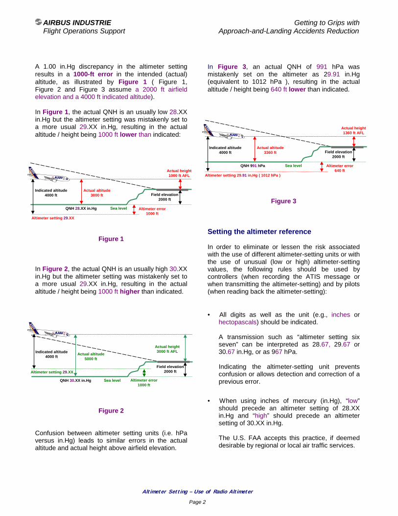
AIRBUS INDUSTRIE Getting to Grips with
Flight Operations Support Approach-and-Landing Accidents Reduction
Altimeter Setting – Use of Radio Altimeter
Page 2
A 1.00 in.Hg discrepancy in the altimeter setting results in a 1000-ft error in the intended (actual) altitude, as illustrated by Figure 1 ( Figure 1, Figure 2 and Figure 3 assume a 2000 ft airfield elevation and a 4000 ft indicated altitude). In Figure 1, the actual QNH is an usually low 28.XX in.Hg but the altimeter setting was mistakenly set to a more usual 29.XX in.Hg, resulting in the actual altitude / height being 1000 ft lower than indicated:
Figure 1 In Figure 2, the actual QNH is an usually high 30.XX in.Hg but the altimeter setting was mistakenly set to a more usual 29.XX in.Hg, resulting in the actual altitude / height being 1000 ft higher than indicated.
Figure 2 Confusion between altimeter setting units (i.e. hPa versus in.Hg) leads to similar errors in the actual altitude and actual height above airfield elevation.
In Figure 3, an actual QNH of 991 hPa was mistakenly set on the altimeter as 29.91 in.Hg (equivalent to 1012 hPa ), resulting in the actual altitude / height being 640 ft lower than indicated.
Figure 3 Setting the altimeter reference In order to eliminate or lessen the risk associated with the use of different altimeter-setting units or with the use of unusual (low or high) altimeter-setting values, the following rules should be used by controllers (when recording the ATIS message or when transmitting the altimeter-setting) and by pilots (when reading back the altimeter-setting):
• All digits as well as the unit (e.g., inches or hectopascals) should be indicated.
A transmission such as “altimeter setting six seven” can be interpreted as 28.67, 29.67 or 30.67 in.Hg, or as 967 hPa. Indicating the altimeter-setting unit prevents confusion or allows detection and correction of a previous error.
• When using inches of mercury (in.Hg), “low” should precede an altimeter setting of 28.XX in.Hg and “high” should precede an altimeter setting of 30.XX in.Hg.
The U.S. FAA accepts this practice, if deemed desirable by regional or local air traffic services.
Sea level
Indicated altitude 4000 ft Field elevation
2000 ft
Actual height1000 ft AFL
Altimeter setting 29.XX
QNH 28.XX in.Hg
Actual altitude3000 ft
Altimeter error 1000 ft
Sea level
Indicated altitude 4000 ft Field elevation
2000 ft
Actual height1360 ft AFL
Altimeter setting 29.91 in.Hg ( 1012 hPa )
QNH 991 hPa
Actual altitude3360 ft
Altimeter error 640 ft
Sea level
Indicated altitude 4000 ft
Field elevation 2000 ft
Actual height3000 ft AFL
Altimeter setting 29.XX
QNH 30.XX in.Hg
Actual altitude5000 ft
Altimeter error 1000 ft
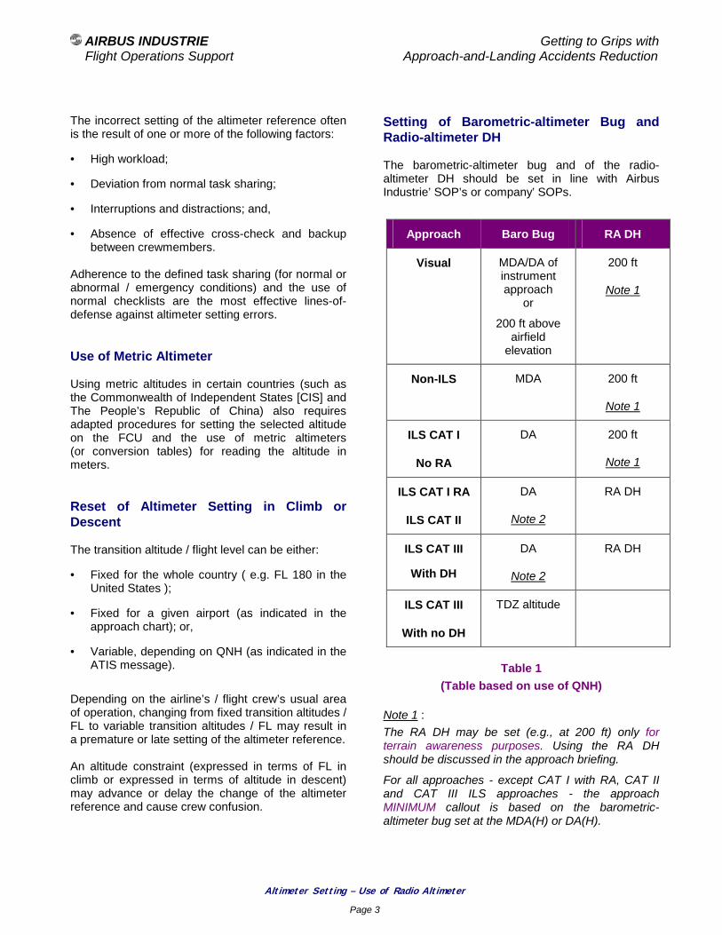
AIRBUS INDUSTRIE Getting to Grips with
Flight Operations Support Approach-and-Landing Accidents Reduction
Altimeter Setting – Use of Radio Altimeter
Page 3
The incorrect setting of the altimeter reference often is the result of one or more of the following factors:
• High workload;
• Deviation from normal task sharing;
• Interruptions and distractions; and,
• Absence of effective cross-check and backup between crewmembers.
Adherence to the defined task sharing (for normal or abnormal / emergency conditions) and the use of normal checklists are the most effective lines-of-defense against altimeter setting errors. Use of Metric Altimeter Using metric altitudes in certain countries (such as the Commonwealth of Independent States [CIS] and The People’s Republic of China) also requires adapted procedures for setting the selected altitude on the FCU and the use of metric altimeters (or conversion tables) for reading the altitude in meters. Reset of Altimeter Setting in Climb or Descent The transition altitude / flight level can be either:
• Fixed for the whole country ( e.g. FL 180 in the United States );
• Fixed for a given airport (as indicated in the approach chart); or,
• Variable, depending on QNH (as indicated in the ATIS message).
Depending on the airline’s / flight crew’s usual area of operation, changing from fixed transition altitudes / FL to variable transition altitudes / FL may result in a premature or late setting of the altimeter reference. An altitude constraint (expressed in terms of FL in climb or expressed in terms of altitude in descent) may advance or delay the change of the altimeter reference and cause crew confusion.
Setting of Barometric-altimeter Bug and Radio-altimeter DH The barometric-altimeter bug and of the radio-altimeter DH should be set in line with Airbus Industrie’ SOP’s or company’ SOPs.
Approach Baro Bug RA DH
Visual MDA/DA of instrument approach
or
200 ft above airfield
elevation
200 ft
Note 1
Non-ILS MDA 200 ft
Note 1
ILS CAT I
No RA
DA 200 ft
Note 1
ILS CAT I RA
ILS CAT II
DA
Note 2
RA DH
ILS CAT III
With DH
DA
Note 2
RA DH
ILS CAT III
With no DH
TDZ altitude
Table 1
(Table based on use of QNH) Note 1 : The RA DH may be set (e.g., at 200 ft) only for terrain awareness purposes. Using the RA DH should be discussed in the approach briefing.
For all approaches - except CAT I with RA, CAT II and CAT III ILS approaches - the approach MINIMUM callout is based on the barometric-altimeter bug set at the MDA(H) or DA(H).

AIRBUS INDUSTRIE Getting to Grips with
Flight Operations Support Approach-and-Landing Accidents Reduction
Altimeter Setting – Use of Radio Altimeter
Page 4
ote 2 : CAT III DA, or the CAT I DA in readiness for a possible reversion to CAT I minimas. Radio-altimeter Callouts Radio-altimeter callouts can be either:
• Announced (verbalized) by the PNF or the Flight Engineer; or,
• Automatically generated by a synthesized voice.
Callouts should be tailored to the airline’ operating policy and to the type of approach. To enhance the flight crew’s terrain awareness, a callout “ Radio altimeter alive “, should be announced by the first crewmember observing the radio altimeter activation at 2500 ft height AGL. The radio altimeter reading should then be included in the instrument scanning for the remainder of the approach. Radio altimeter readings below obstacle clearance levels listed below, should alert the flight crew:
• Initial approach : 1000 ft AGL;
• Intermediate approach (or minimum radar vectoring altitude) : 500 ft AGL;
• Final approach (non-precision approaches with defined FAF) : 250 ft AGL.
Note : The radio altimeter indicates the aircraft current height above the ground (height AGL) and not the height above the airfield elevation. Unless the airport features high close-in terrain, the radio-altimeter reading should reasonably agree with the height above airfield elevation (obtained by direct reading of the altimeter if using QFE or by computation if using QNH). Low OAT Operation In a standard atmosphere, the indicated altitude reflects the true altitude above the mean sea level (MSL) and therefore provides a reliable indication of terrain clearance.
Whenever, the temperature deviates significantly from the standard temperature, the indicated altitude correspondingly deviates from the true altitude, as follows:
• Extreme high temperature :
− the true altitude is higher than the indicated altitude,
• Extreme low temperature :
− the true altitude is lower than the indicated altitude, thus creating a lower than anticipated terrain separation and a potential obstacle-clearance hazard.
For example, when performing an ILS approach with a published 2000 ft minimum glide-slope interception-altitude and a – 40 ° C OAT, the minimum glide-slope interception altitude should be increased by 480 ft. Figure 4
Effect of OAT on True Altitude The ICAO PANS-OPS, Volume I, provides altitude corrections to be added to the published minimum safe altitudes (heights). The temperature correction (i.e., correction to be added to the indicated altitude) depends on the aerodrome surface temperature and on the desired true altitude (height) above the elevation of the altimeter-setting source.
Given atmospheric pressure( pressure altitude )
True altitude
Low OATHigh OAT
Indicatedaltitude
2000 ft 3000 ft
2000 ft
1000 ft
Standard OAT
1520 ft
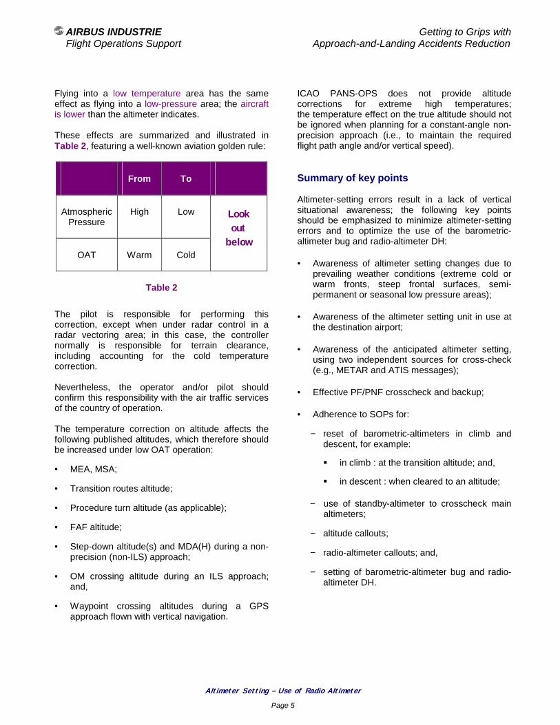
AIRBUS INDUSTRIE Getting to Grips with
Flight Operations Support Approach-and-Landing Accidents Reduction
Altimeter Setting – Use of Radio Altimeter
Page 5
Flying into a low temperature area has the same effect as flying into a low-pressure area; the aircraft is lower than the altimeter indicates. These effects are summarized and illustrated in Table 2, featuring a well-known aviation golden rule:
From To
Atmospheric Pressure
High Low
OAT Warm Cold
Look out
below
Table 2
The pilot is responsible for performing this correction, except when under radar control in a radar vectoring area; in this case, the controller normally is responsible for terrain clearance, including accounting for the cold temperature correction. Nevertheless, the operator and/or pilot should confirm this responsibility with the air traffic services of the country of operation. The temperature correction on altitude affects the following published altitudes, which therefore should be increased under low OAT operation:
• MEA, MSA;
• Transition routes altitude;
• Procedure turn altitude (as applicable);
• FAF altitude;
• Step-down altitude(s) and MDA(H) during a non-precision (non-ILS) approach;
• OM crossing altitude during an ILS approach; and,
• Waypoint crossing altitudes during a GPS approach flown with vertical navigation.
ICAO PANS-OPS does not provide altitude corrections for extreme high temperatures; the temperature effect on the true altitude should not be ignored when planning for a constant-angle non-precision approach (i.e., to maintain the required flight path angle and/or vertical speed). Summary of key points Altimeter-setting errors result in a lack of vertical situational awareness; the following key points should be emphasized to minimize altimeter-setting errors and to optimize the use of the barometric-altimeter bug and radio-altimeter DH:
• Awareness of altimeter setting changes due to prevailing weather conditions (extreme cold or warm fronts, steep frontal surfaces, semi-permanent or seasonal low pressure areas);
• Awareness of the altimeter setting unit in use at the destination airport;
• Awareness of the anticipated altimeter setting, using two independent sources for cross-check (e.g., METAR and ATIS messages);
• Effective PF/PNF crosscheck and backup;
• Adherence to SOPs for:
− reset of barometric-altimeters in climb and descent, for example:
! in climb : at the transition altitude; and,
! in descent : when cleared to an altitude;
− use of standby-altimeter to crosscheck main altimeters;
− altitude callouts;
− radio-altimeter callouts; and,
− setting of barometric-altimeter bug and radio-altimeter DH.

AIRBUS INDUSTRIE Getting to Grips with
Flight Operations Support Approach-and-Landing Accidents Reduction
Altimeter Setting – Use of Radio Altimeter
Page 6
Associated Briefing Notes The following Briefing Notes also refer to altimeter-setting and altitude issues:
• 1.1 - Operating Philosophy – SOPs,
• 2.3 - Effective Crew/ATC Communications,
• 2.4 - Intra-Cockpit Communications – Managing Interruptions and Distractions,
• 3.2 - Altitude Deviations. Regulatory references
• ICAO Annex 3 – Meteorological Service for International Air navigation, Chapter 4.
• ICAO Annex 5 – Units of Measurement to be used in Air and Ground Operations, Table 3-4, 3.2.
• ICAO Annex 6 – Operations of Aircraft, Part I – International Commercial Air transport – Aeroplane, 6.9.1 c) and Appendix 2, 5.13.
• ICAO Annex 6 – Procedures for Air Navigation Services – Rules of the Air and Air Traffic Services (PANS-RAC, Doc 4444).
• ICAO Annex 6 – Procedures for Air navigation Services – Aircraft Operations (PANS-OPS, Doc 8168), Volume I – Flight procedures - Part VI – Altimeter Setting Procedures - Chapter 3 - New table of temperature corrections to be added to the indicated altitude when operating in low OAT conditions.
The new Part VI – Chapter 3 will be effective in Nov.2001 and will replace and supersede the current Chapter 3 of Part III.
• Preparation of an Operations manual (Doc 9376).
• Manual of radiotelephony (Doc 9432).
• Human Factors Training Manual (Doc 9683).
• Human Factors Digest No.8 – Human Factors in Air Traffic Control (Circular 241).
• FAA - Draft AC 91-XX - Altimeter Errors at Cold Temperatures.

AIRBUS INDUSTRIE Getting to Grips with Flight Operations Support Approach-and-Landing Accidents Reduction
Altitude Deviations
Page 1
Approach-and-Landing Briefing Note
3.2 - Altitude Deviations
Introduction Altitude deviations may result in substantial loss of vertical separation and/or horizontal separation, which could cause a midair collision. Traffic avoidance maneuvers, if required, usually result in injuries to passengers and crewmembers (particularly to cabin crewmembers). This Briefing Note provides an overview of the factors involved in altitude deviations. This document can be used for stand-alone reading or as the basis for the development of an airline’s altitude awareness program. Statistical Data An analysis by the U.S. FAA and by US Airways indicates that:
• Approximately 70 % of altitude deviations are the result of a breakdown in the pilot/controller communication loop; and,
• Nearly 40 % of altitude deviation events affect the critical pair constituted by FL 100 / FL 110 (or 10 000 ft / 11 000 ft).
Defining an Altitude Deviation An altitude deviation is defined by regulations as a deviation from the assigned altitude (or flight level) equal to or greater than 300 ft.
Factors Involved in Altitude Deviations Altitude deviations usually result from one of the following causes:
• Misunderstanding the assigned altitude;
• Use of an incorrect altimeter setting;
• Failure to level-off at the assigned altitude; or,
• Failure to reach or maintain the assigned altitude (or altitude restriction) at the point or time assigned by ATC.
Altitude deviations always are the result of a breakdown in either:
• the pilot / system interface :
− altimeter setting, use of autopilot, monitoring of instruments and displays; or,
• the pilot / controller interface :
− communication loop.
Altitude deviations occur as the result of one or a combination of the following conditions:
• The controller assigns an incorrect altitude, or reassigns a FL after the aircraft has been cleared to an altitude;
AIRBUS INDUSTRIE Getting to Grips with Flight Operations Support Approach-and-Landing Accidents Reduction
Altitude Deviations
Page 2
• Pilot/controller communication breakdown (mainly readback / hearback errors), e.g.:
− Controller transmits an incorrect altitude, the pilot does not readback and the controller does not challenge the absence of readback;
− Pilot understands and readback an incorrect altitude but controller does not hear back and does not correct the crew readback; or,
− Pilot accepts an altitude clearance intended for another aircraft (confusion of callsigns);
• Pilot understands and reads back the correct altitude or FL, but select an incorrect altitude or FL , e.g. because of :
− confusion of numbers with an other element of the message (e.g., speed, heading or flight number);
− expectation / anticipation of another altitude or FL;
− interruption / distraction; or,
− breakdown in crew crosscheck and backup;
• Autopilot fails to capture the selected altitude;
• Absence of response to the altitude alert aural and visual warnings, when in hand flying; or,
• Incorrect go-around procedure and maneuver. Altitude Awareness Program The development and implementation of altitude awareness programs by several airlines have reduced significantly the number of altitude deviations. To address the main causes of altitude deviations, an altitude awareness program should include the following aspects.
General: An altitude awareness program should enhance the monitoring role of the PF and PNF by stressing the importance of:
• Stating (verbalizing) intentions and actions, when they are different from expectations (e.g., delayed climb or descent, management of altitude or speed restrictions); and,
• Backing up each other. Communications: Breakdown in the pilot/controller communication loop includes:
• Readback / hearback errors ( this risk is greater when one crewmember does not monitor radio communications because of other duties such as listening to the ATIS or being involved in company communications or passenger-address announcements );
• Blocked transmissions; or,
• Confusion of call signs.
The following recommendations (discussed and expanded in Briefing Note 2.3 - Effective Pilot / Controller Communications) can enhance communications and raise the level of situational awareness of pilots and controller:
• Be aware that readback / hearback errors involve may the pilot and the controller :
− The pilot may be interrupted or distracted when listening to a clearance, confuse similar callsigns, forget an element of the instruction or be subject to the bias of expectation when understanding or when reading back the instruction ( this bias usually is referred to as wishhearing );
− The controller may also confuse similar callsigns, be distracted by other radio or landline telephone communications or be affected by blocked transmissions or high workload.

AIRBUS INDUSTRIE Getting to Grips with Flight Operations Support Approach-and-Landing Accidents Reduction
Altitude Deviations
Page 3
• Use standard phraseology for clear and unambiguous pilot / controller and intra-cockpit communications. Standard phraseology is the common basis for pilots and controllers; this common language allows an easier detection and correction of errors.
• Use of an adapted phraseology to increase the controller situational awareness, e.g.:
− When leaving an altitude, announce:
Leaving […] for […]; or,
Leaving […] and climbing / descending to […];
The call leaving … should be performed only when a vertical speed of 500 ft/mn has been established and the altimeter positively shows the departure from the previous altitude or FL;
This recommendation takes a particular importance when descending in a holding pattern;
− Use of two separate methods for expressing certain altitudes – one one thousand feet, that is eleven thousand feet; and,
− Preceding each number by the corresponding flight parameter (i.e., FL, heading, speed), e.g., descend to Flight Level two four zero instead of descend to two four zero.
• If doubt exists about a clearance, request confirmation from ATC, do not attempt to guess an instruction or clearance based on flight deck discussion.
Task prioritization and task sharing: The following guidelines and recommendations should be considered for optimum prioritization of tasks and task sharing:
• Reduce non-essential tasks during climb and descent ( in addition to the sterile cockpit rule, some operators consider the last 1000 ft before reaching any assigned altitude as a sterile-cockpit period );
• Monitor / supervise the operation of AP for correct level-off at the cleared altitude and for correct compliance with altitude or time restrictions (constraints);
• Plan tasks that prevent attentive listening to radio communications (such as copying the ATIS, company calls, and passengers-address announcements) during periods of less ATC communication.
• When one crewmember cannot monitor the ATC frequency because of other duties or because leaving the cockpit, the other crewmember should :
− Acknowledge receiving the radio and controls, as applicable;
− Check the radio volume to ensure adequate reception of ATC calls;
− Give an increased attention to listening / confirming / reading back (because of the momentary absence of backup ); and,
− Brief the other crew member when he/she returns, highlighting any relevant new information and any change in the ATC clearance or instructions.
Altitude-setting procedures: The following techniques should be considered for enhancing standard operating procedures (SOPs):
• When receiving an altitude clearance, set the cleared altitude value immediately in the selected altitude window (even before readback, if deemed more suitable due to workload);
• Ensure that the altitude selected is cross-checked by both crewmembers (e.g., each crew member should verbalize what he or she heard and then point to the selected altitude window to confirm that the correct value has been set);
• Ensure that the cleared altitude is above the sector minimum safe altitude; and,
• When under radar vectoring, be aware of the applicable minimum vectoring altitude for the sector or positively request confirmation of an altitude clearance below the sector MSA.

AIRBUS INDUSTRIE Getting to Grips with Flight Operations Support Approach-and-Landing Accidents Reduction
Altitude Deviations
Page 4
Callouts: Use standard calls to increase the PF / PNF situational awareness, to ensure an effective backup and challenge, and detect a previous error on the assigned / cleared altitude or FL:
• Modes changes on FMA and changes of targets on PFD/ND;
• Leaving [...] for […] , when a 500 ft/mn vertical speed has been established; and altimeter indicates departure from the previous altitude; and,
• One to go ;
One thousand to go “; or,
[…] for […],
when within 1000 ft from the cleared altitude or FL.
When within 1000 ft from the cleared altitude / FL or from an altitude restriction (constraint):
• PF should concentrate on instruments scanning (one head in); and,
• PNF should watch outside for traffic, if in VMC (one head out).
Flight Level or Altitude Confusion Confusion between FL 100 and FL 110 (or between 10 000 ft / 11 000 ft) is usually the result of the combination of two or more of the following factors:
• Readback / hearback error because of similar sounding phrases;
• Absence of standard phraseology :
− ICAO : FL one zero zero / FL one one zero;
− U.K. NATS: FL one hundred / FL one one zero;
• Mindset leaning to focus only on “one zero” and thus to more easily understand “10 000 feet”;
• Failing to question the unusual (e.g. bias of expectation or routine on a familiar SID or STAR) and/or,
• Interpreting subconsciously a request to slow down to 250-kt as a clearance to descend to FL 100.
Transition Altitude / Level As indicated in Briefing Note 3.1 - Altimeter Setting – Use of radio Altimeter, the transition altitude / flight level can be either:
• Fixed for the whole country ( e.g. FL 180 in the United States);
• Fixed for a given airport (as indicated in the approach chart); or,
• Variable as a function of QNH (as indicated in the ATIS message).
Depending on the airline’s / flight crew’s usual area of operation, changing from fixed transition altitudes/FL to variable transition altitudes/FL may result in a premature or late change of the altimeter setting. An altitude constraint (expressed in terms of FL in climb or expressed in terms of altitude in descent) may advance or delay the change of altimeter setting and cause crew confusion. In countries operating with reference to the QFE, when below the transition altitude or FL, the readback should indicate the altimeter reference (i.e., QFE). Altitude Deviations in Holding Patterns In holding patterns controllers rely on pilots maintained the assigned altitude or to descend to the new cleared altitude. The overlay of aircraft tags on the controller’s radar display does not allow the immediate detection of an impending traffic conflict. Controllers, therefore, assume that a correctly readback clearance will be correctly complied with.

AIRBUS INDUSTRIE Getting to Grips with Flight Operations Support Approach-and-Landing Accidents Reduction
Altitude Deviations
Page 5
Secondary surveillance radar’s (SSR) provide conflict alerts but no resolution advisory; accurate and clear pilot / controller communications are essential when descending in a holding pattern. Two separate holding patterns may be controlled by the same controller, on the same frequency. The following communication rules are, therefore, important when in a holding pattern:
• Do not take a communication intended for an other aircraft (by confusion of similar callsigns);
• Prevent / minimize the risk of blocked transmission, in case of simultaneous readback by two aircraft with similar callsigns or simultaneous transmissions by the pilot and the controller; and,
• Announce leaving [FL or altitude] only when the vertical speed indicator and the altimeter reflect the departure from the previous altitude.
Summary of Key Points An altitude awareness program should be emphasized during transition and recurrent training and during line checks. Blame-free reporting of altitude deviation events should be encourage to broaden the understanding of causal and circumstantial factors resulting in altitude deviations. The following safety key points should be promoted:
• Adhere to the pilot / controller readback / hearback process (communication circle);
• Crosscheck and backup each other to ensure that the altitude selected is the cleared altitude received;
• Cross-check that the cleared altitude is above the sector minimum safe altitude (unless crew is aware of the applicable minimum vectoring altitude for the sector);
• Monitor instruments and automation when reaching the cleared altitude or FL; and,
• In VMC, apply the technique one head inside / one head out when reaching the cleared altitude or FL.
The TCAS (ACAS) is an effective safeguard to minimize the consequences of altitude deviations. Altitude deviations can be prevented by strict adherence to adequate SOPs, this includes:
• Setting the altimeter-reference on barometric altimeters; and,
• Selecting the cleared altitude or FL on the FCU. Associated Briefing Notes The following Briefing Notes refer to altimeter setting and altitude issues:
• 1.1 - Operating Philosophy - SOPs,
• 1.3 - Operations Golden Rules,
• 1.4 - Standard Calls,
• 2.3 - Effective Pilot / Controller Communications,
• 2.4 - Intra-crew Communications – Managing Interruptions and Distractions,
• 3.2 - Altimeter Setting – Use of radio Altimeter.

AIRBUS INDUSTRIE Getting to Grips with Flight Operations Support Approach-and-Landing Accidents Reduction
Altitude Deviations
Page 6
Regulatory references
• ICAO Annex 6, Parts I, II and III, Sections II and III (amended in 1995) for discouraging the use of three-pointer and drum-pointer altimeters.
• ICAO Annex 6, Operation of Aircraft, Part I – International Commercial Air Transport – Aeroplanes, 4.2.6, 6.9.1 c) and Appendix 2, 5.13, 5.15.
• ICAO – Procedures for Air Navigation Services – Rules of the Air and Air Traffic Services (PANS-RAC, Doc 4444).
• ICAO – Procedures for Air Navigation Services – Aircraft Operations (PANS-OPS, Doc 8168), Volume I, Flight Procedures (Post Amendment No 11, applicable 1 November 2001).
• FAR 91.119 for minimum safe altitude.
• FAR 91.121 for altimeter setting.
• FAR 91.129 for clarification of ATC com-munications.
• FAR 91.221 and FAR 121.356 for TCAS installation.
• FAA Draft AC 91-XX – Altimeter Errors at Cold Temperatures.
• UK CAA CAP 413 for required criteria in announcing leaving an altitude or FL.

AIRBUS INDUSTRIE Getting to Grips with Flight Operations Support Approach-and-Landing Accidents Reduction
Chapter 4
Descent and Approach Management
AIRBUS INDUSTRIE Getting to Grips with Flight Operations Support Approach-and-Landing Accidents Reduction
Descent and Approach Profile Management
Page 1
Approach-and-Landing Briefing Note
4.1 - Descent and Approach Profile Management
Introduction Inadequate management of descent-and-approach profile and/or incorrect management of aircraft energy level during approach may in:
• Loss of vertical situational awareness; and/or,
• Rushed and unstabilized approaches.
Either situation increases the risk of approach-and-landing accidents, including those involving CFIT. Statistical Data Approximately 70 % of rushed and unstable approaches involve an inadequate management of the descent-and-approach profile and/or an incorrect management of energy level; this includes:
• Being higher or lower than the desired vertical flight path; and/or,
• Being faster or slower than the desired speed. Best Practices and Guidelines To prevent delay in initiating the descent and to ensure an optimum management of descent-and-approach profile, descent preparation and approach/go-around briefings should be completed typically 10 minutes before the top-of-descent (or when within VHF communication range).
Descent Preparation:
• If a standard terminal arrival route (STAR) is included in the FMS flight plan but is not expected to be flown, because of anticipated radar vectors, the STAR should be checked (i.e., the track-distance, altitude restrictions and/or speed restrictions) against the anticipated routing to adjust the top-of-descent point accordingly; and,
• Wind forecast should be entered (as available) on the appropriate FMS page, at waypoints close to the top-of-descent point and along the descent profile.
Descent and Approach Briefing:
• If a missed-approach is included in the FMS flight plan, the missed approach should be reviewed against the applicable approach chart.
Descent Initiation:
• If descent initiation is delayed by ATC, reduce speed as appropriate to minimize the impact on the descent profile.
Navigation Accuracy Check:
• If FMS navigation accuracy does not meet the applicable criteria for terminal area navigation or approach, no descent should be made below the MEA or below the sector MSA without prior confirmation of the aircraft position, using navaids raw-data.

AIRBUS INDUSTRIE Getting to Grips with Flight Operations Support Approach-and-Landing Accidents Reduction
Descent and Approach Profile Management
Page 2
Concept of next target and decision gates: Throughout the entire flight a next target should be defined, in order to stay ahead of the aircraft at all times. The next target should be any required combination of one or more of the following elements:
• A position;
• An altitude;
• A configuration;
• A speed;
• A vertical speed (as applicable); and,
• A power setting.
If it is anticipated that one or more element(s) of the next target will not be met, the required corrective action(s) should be taken without delay. During the approach and landing, the successive next targets should constitute gates that must be met for the approach to be continued. The final approach fix (FAF), the outer marker (OM) or an equivalent fix (as applicable) should constitute an assessment gate to confirm the readiness to proceed further; this assessment should include the following:
• Visibility or RVR (and ceiling, as appropriate):
! better than or equal to applicable minimums;
• Aircraft readiness:
! position, altitude, configuration and energy; and,
• Crew readiness:
! briefing completed and agreement on approach conditions.
The stabilization height should constitute a decision gate; if the required configuration and speed are not obtained or if the flight path is not stabilized when reaching the stabilization height, an immediate go-around should be initiated.
A callout should be performed by the PNF if a flight parameter exceeds the criteria for one of the elements of a stabilized approach, as described in Briefing Note 7.1 - Flying Stabilized Approaches. Descent Profile Monitoring: Descent profile should be monitored, using all available instrument and chart references:
• FMS vertical-deviation indication, as applicable;
• Navaids and instruments raw-data; and,
• Charted descent-and-approach profile.
Wind conditions and wind changes should be monitored closely to anticipate any reduction in head wind component or increase in tail wind component, and to adjust the flight path profile in a timely manner. The descent profile may be monitored and adjusted based on a typical 3000 ft per 10 nm descent gradient (corrected for the prevailing head wind component or tail wind component), while complying with the required altitude and/or speed restrictions (i.e., ensuring adequate deceleration management). The flight path vector, as available, can be used to monitor the descent profile by checking that the remaining track-distance to touchdown (in nm) is approximately equal to the FL divided by the flight-path-angle (FPA, in degrees):
Distance-to-go (nm) = FL / FPA (degrees) Note : In the above rule, the FL should be understood as the FL difference (∆ FL) between the current aircraft FL and the airfield FL. Below 10 000 ft, flying at 250 kt IAS, the following guidelines may be used to confirm the descent profile and ensure a smooth transition between the various phases of the approach:
• 9000 ft above airport elevation at 30 nm from touchdown; and,
• 3000 ft above airport elevation at 15 nm from touchdown (to account for deceleration and slats/flaps extension).

AIRBUS INDUSTRIE Getting to Grips with Flight Operations Support Approach-and-Landing Accidents Reduction
Descent and Approach Profile Management
Page 3
Descent Profile Adjustment/Recovery: If flight path is significantly above the desired descent profile (e.g. because of an ATC constraint or a higher-than-anticipated tail wind), to recover the desired flight path:
• Revert from FMS vertical navigation to a selected vertical mode, with an appropriate speed target;
• Maintain a high airspeed as long as practical;
• Extend speed brakes (as allowed by SOPs depending on airspeed and configuration, keeping one hand on the speed brakes handle until speed brakes are retracted); or,
• Extend landing gear, if the use of speed brakes is not sufficient; or,
• As a last resort, perform a 360-degree turn (as practical and cleared by ATC).
Maintain close reference to instruments throughout the turn to monitor and control the rate of descent, bank angle and position, to prevent:
! loss of control;
! CFIT; or,
! overshoot of the localizer and/or of the extended runway centerline.
If the desired descent flight path cannot be recovered, notify ATC for timely coordination. Refer to Briefing Note 4.2 - Energy Management during Approach for additional information. Adverse Factors and Typical Errors The following factors and working errors often are observed during transition and line training:
• Late and therefore rushed descent and approach preparation and briefing, resulting in the omission of important items;
• Failure to cross-check FMS data entries;
• Failure to account for differences between expected routing and actual routing (i.e., STAR versus radar vectors);
• Distraction leading to or resulting from a two-heads-down situation;
• Failure to resolve ambiguities, doubts or disagreements;
• Failure to effectively monitor the descent progress using all available instrument references (e.g., failure to monitor wind conditions and/or wind changes); and/or,
• Use of inappropriate technique to recover the descent profile.
Summary of Key Points The following key points should be emphasized during transition training and line training as well as during line checks and line audits:
• Timeliness of descent and approach preparation;
• Strict adherence to SOPs for FMS setup;
• Cross-check of all data entries by both crewmembers;
• Use of PFD, ND and FMS CDU to support and illustrate the descent, approach and go-around briefings;
• Confirmation of FMS navigation accuracy, before deciding the use of automation (i.e., use of FMS modes or selected modes) for the descent and approach;
• Review of terrain information and other approach hazards; and,
• Guidelines for descent planning, monitoring and adjustment.
AIRBUS INDUSTRIE Getting to Grips with Flight Operations Support Approach-and-Landing Accidents Reduction
Descent and Approach Profile Management
Page 4
Associated Briefing Notes The following Briefing Notes may be referred to for a complete overview of the procedures, operational recommendations and techniques involved in the conduct of the descent and approach:
• 1.1 - Standard Operating Procedures,
• 1.3 - Operations Golden Rules,
• 4.2 - Energy Management during Approach,
• 5.2 - Terrain Awareness,
• 6.1 - Being Prepared for Go-around,
• 7.1 - Flying Stabilized Approaches. Regulatory References
• ICAO – Annex 6 – Operation of Aircraft, Part I – International Commercial Air Transport – Aeroplanes, Appendix 2 – Contents of Operations Manuals, 5.18, 5.19.
• ICAO – Procedures for Air navigation Services – Aircraft Operations (PANS-OPS, Doc 8168), Volume I – Flight procedures.
• FAA AC 120-71 – Standard Operating Procedures for Flightdeck Crew Members.
• JAR-OPS 1.1045 and associated Appendix A, 2.1 – Operations Manuals – structure and contents.

AIRBUS INDUSTRIE Getting to Grips with Flight Operations Support Approach-and-Landing Accidents Reduction
Energy Management during Approach
Page 1
Approach-and-Landing Briefing Note
4.2 - Energy Management during Approach
Introduction Inability to assess or manage the aircraft energy level during the approach often is cited as a causal factor in unstabilized approaches. Either a deficit of energy (being low and/or slow) or an excess of energy (being high and/or fast) may result in approach-and-landing accidents, such as:
• Loss of control;
• Landing short;
• Hard landing;
• Tail strike;
• Runway excursion; and/or,
• Runway overrun.
This Briefing Note provides background information and operational guidelines for a better understanding:
• Energy management during intermediate approach:
− How fast can you fly down to the FAF or outer marker ?
• Energy management during final approach:
− Hazards associated with flying on the backside of the power curve (as defined by Figure 2).
Refer also to Briefing Note 7.2 – The Final Approach Speed.
Statistical Data Approximately 70 % of rushed and unstable approaches involve an incorrect management of the aircraft energy level, resulting in an excess or deficit of energy, as follows:
• Being slow and/or low on approach : 40 % of events; or,
• Being fast and/or high on approach: 30 % of events.
Aircraft Energy Level The level of energy of an aircraft is a function of the following primary flight parameters and of their rate of change (trend):
• Airspeed and speed trend;
• Altitude and vertical speed (or flight path angle);
• Drag (i.e., drag caused by speed brakes, slats/flaps and/or landing gear); and,
• Thrust level.
One of the tasks of the pilot is to control and monitor the energy level of the aircraft (using all available cues) in order to:
• Maintain the aircraft at the appropriate energy level for the flight phase and configuration:
− flight path, speed and thrust; or,
• Recover the aircraft from a low energy or high energy situation, i.e., from:
− being too slow and/or too low; or,
− being too fast and/or too high.

AIRBUS INDUSTRIE Getting to Grips with Flight Operations Support Approach-and-Landing Accidents Reduction
Energy Management during Approach
Page 2
Controlling the aircraft energy level implies balancing the airspeed, thrust (and drag) and flight path, or transiently trading one parameter for another. Autopilot and flight director modes, aircraft instruments, warnings and protections are designed to relieve or assist the flight crew in these tasks.
Going Down and Slowing Down :
How Fast Can you Fly Down to the Marker? A study by the U.S. NTSB acknowledges that maintaining a high airspeed down to the outer marker (OM) does not favor the capture of the glideslope beam by the autopilot or the aircraft stabilization at the defined stabilization height. The study concludes that no speed restriction should be imposed when within 3 nm to 4 nm before the OM, mainly in instrument meteorological conditions (IMC). Nevertheless, ATC requests for maintaining a high airspeed down to the marker (160 kt to 200 kt IAS typically) are frequent at high-density airports, to increase the landing rate. The purpose of the following part is to:
• Recall the definition of stabilization heights;
• Illustrate the aircraft deceleration characteristics in level flight and on a 3-degree glide path; and,
• Provide guidelines for assessment of the maximum speed which, reasonably, can be maintained down to the marker, as a function of:
− the distance from the OM to the runway threshold; and,
− the desired stabilization height. Stabilization height: The definition and criteria for a stabilized approach are defined in Briefing Note 7.1 - Flying Stabilized Approaches.
The minimum stabilization height should be:
• 1000 ft above airfield elevation in IMC;
• 500 ft above airfield elevation in VMC. Airlines usually require flight crews to cross the outer marker (i.e., typically between 1500 ft and 2000 ft above airfield elevation) with the aircraft configured in the landing configuration. This allows time, before reaching the applicable stabilization height, for:
• Stabilizing the final approach speed; and,
• Completing the landing checklist.
Aircraft deceleration characteristics: Although deceleration characteristics largely depends on the aircraft type and gross-weight, the following typical values can be considered for a quick assessment and management of the aircraft deceleration capability:
• Deceleration in level flight:
− with approach flaps extended:
§ 10 to 15 kt-per-nm;
− during extension of gear and landing flaps:
§ 20 to 30 kt-per-nm;
• Deceleration on a 3-degree glide path:
− with approach flaps and gear down, during extension of landing flaps:
§ 10 to 20 kt per nm.
Note: A 3-degree glide path is typically equivalent to a descent-gradient of 300 ft-per-nm or a 700 ft/mn vertical speed, for a final approach ground speed of 140 kt.
Decelerating on a 3-degree glide path in clean configuration usually is not possible.
When capturing the glide slope with only slats extended (i.e., with no flaps), typically 1000-ft and 3 nm are flown while establishing the landing configuration and stabilizing at the target final approach speed.

AIRBUS INDUSTRIE Getting to Grips with Flight Operations Support Approach-and-Landing Accidents Reduction
Energy Management during Approach
Page 3
Speedbrakes may be used to achieve a faster deceleration, as allowed for the aircraft type. Usually the use of speedbrakes is not recommended or not permitted when below 1000 ft above airfield elevation and/or in the landing flaps configuration. Typically, slats should be extended not later than 3 nm before the FAF.
Figure 1 illustrates the aircraft deceleration capability and the maximum possible speed at the OM, based on a conservative deceleration rate of 10 kt per nm on a 3-degree glide path. The following conditions are considered:
• IMC (stabilization height 1000 ft above airfield elevation); and,
• Final approach speed ( V APP ) = 130 kt.
The maximum deceleration achievable between the OM (typically 6.0 nm from the runway threshold) and the stabilization point ( 1000 ft above airfield elevation / 3.0 nm ) is:
10 kt-per-nm x ( 6.0 – 3. 0 ) nm = 30 kt In order to be stabilized at 130 kt at 1000 above airfield elevation, the maximum speed that can be accepted and maintained down to the OM is therefore:
130 kt + 30 kt = 160 kt
Figure 1
Deceleration along Glide Slope - Typical Whenever being required to maintain a high speed down to the marker, the above quick computation may be considered for assessing the feasibility of the ATC request. Avoiding the Back Side of the Power Curve During an unstable approach, the airspeed or the thrust setting often is observed to deviate from the target values:
• Airspeed is below the target final approach speed ( V APP ); and/or,
• Thrust is reduced and maintained at idle.
6
1000 ft
3
MM OM
500 ft
2000 ft
V APP = 130 kt V MAX at OM = 160 kt
Deceleration Segment
( 10 kt/nm )
06.0 3.0 0 nm

AIRBUS INDUSTRIE Getting to Grips with Flight Operations Support Approach-and-Landing Accidents Reduction
Energy Management during Approach
Page 4
Thrust-required-to-fly curve: Figure 2 illustrates the thrust-required-to-fly curve (also referred to as the power curve). Figure 2
Power Curve - Typical The power curve features the following elements:
• A point of minimum thrust-required-to-fly;
• A part located right of this point;
• A part located left of this point, called the backside of the power curve.
The difference between the available-thrust and the thrust-required-to-fly (i.e., the thrust balance):
• Represents the climb or acceleration capability (if the available-thrust exceeds the required-thrust); or,
• Indicates that speed and/or flight path cannot be maintained (if the required-thrust exceeds the available-thrust).
The right side of the power curve is the normal zone of operation.
The thrust balance is such that, at given thrust level, any tendency to accelerate increases the thrust-required-to-fly and, hence, brings back the aircraft to the initial airspeed.
Conversely, any tendency to decelerate decreases the thrust-required-to-fly and, hence, brings back the aircraft to the initial airspeed
On the backside of the power curve, the thrust balance is such that, at given thrust level, any tendency to decelerate increases the thrust-required-to-fly and, hence, amplifies the tendency to decelerate.
Conversely any tendency to accelerate decreases the thrust-required-to-fly and, hence, amplifies the tendency to accelerate.
The minimum thrust speed ( V minimum thrust ) usually is equal to 1.35 to 1.4 V stall, in landing configuration.
The minimum final approach speed is slightly in the backside of the power curve.
If the airspeed is allowed to decrease below the final approach speed, more thrust is required to maintain the desired flight path and/or to regain the target speed.
In addition, if the thrust is set and maintained at idle, no energy is immediately available to recover from a low speed condition or to initiate a go-around (as illustrated in Figure 3, Figure 4 and Figure 5).
Thrust Required to Fly3-degree glide slope - Landing configuration
90
100
110
120
130
140
150
160
90 100 110 120 130 140 150 160 170 180 190 200
Airspeed ( kt )
Th
rust
req
uir
ed -
in %
V APP V minimum thrust
Thrust for V APP
Stable
Given gross-weightGiven pressure altitude
Given fligh path
Unstable

AIRBUS INDUSTRIE Getting to Grips with Flight Operations Support Approach-and-Landing Accidents Reduction
Energy Management during Approach
Page 5
Engine acceleration characteristics: When flying the final approach segment with the thrust set and maintained at idle (approach idle), the pilot should be aware of the acceleration characteristics of jet engines, as illustrated below. Figure 3
Engine Response Scatter- Typical The acceleration capability of a jet engine is controlled to:
• Protect the engine against a stall or flameout; and,
• Comply with the engine and aircraft certification requirements ( U.S. FAR – Part 33 and FAR – Part 25, respectively, or the applicable equivalent regulation).
The engine certification (FAR – Part 33) ensures a time of 5 seconds or less to accelerate from 15% to 95 % of the go-around thrust.
The aircraft certification (FAR – Part 25) ensures that the thrust achieved after 8 seconds (starting from flight/approach idle) allows a minimum climb gradient of 3.2 % for go-around. Figure 4
Certified Thrust Response -Typical
Thrust Response from Idle to GA Thrust( typical engine-to-engine scatter )
0
20
40
60
80
100
0 1 2 3 4 5 6 7 8 9 10
Time ( seconds )
Thr
ust (
in %
GA
thru
st )
Approachidle
Thrust Response - Approach Idle to GA ( aicraft certification requirements )
0
20
40
60
80
100
0 1 2 3 4 5 6 7 8 9 10
Time ( seconds )
Thr
ust (
in %
of G
A th
rust
)
8 seconds (FAR 25)

AIRBUS INDUSTRIE Getting to Grips with Flight Operations Support Approach-and-Landing Accidents Reduction
Energy Management during Approach
Page 6
Go-around from low speed/low thrust: Table 1 indicates the thrust required (in % of the TOGA thrust) during the transition from a stabilized approach to a go-around.
Phase % of TOGA Thrust
Stabilized approach 3-degree glide path / V APP
20 %
Arresting altitude loss 30 %
“Positive Climb” > 30 %
Table 1
Thrust Required during GA Initiation Table 1 and Figure 5 illustrate the importance of being stabilized on speed and on thrust when initiating a go-around.
Figure 5 illustrates the consequences associated with flying an approach with:
• Speed below the target final approach speed ( V APP ); and/or,
• Thrust not stabilized or set and maintained at idle.
In case of go-around, the initial altitude loss and the time required for recovering the initial altitude are increased if airspeed is lower than the final approach speed and/or if thrust is not stabilized or set at idle. Figure 5
Effect of Initial Speed and Thrust
on Altitude Loss during Go-around
(Typical)
Altitude Loss in Go-around( Landing Configuration )
-50
-40
-30
-20
-10
0
10
20
30
0 1 2 3 4 5 6 7 8
Time ( seconds )
Alti
tude
Los
s(
in fe
et fr
om g
o-ar
ound
initi
atio
n )
V APP –10 kt / Idle
V APP / Stabilized thrust
V APP / Idle
V APP / Thrust decreasing
AIRBUS INDUSTRIE Getting to Grips with Flight Operations Support Approach-and-Landing Accidents Reduction
Energy Management during Approach
Page 7
Summary of Key Points A deceleration below the final approach speed should be accepted only in the following cases:
• GPWS terrain avoidance maneuver;
• Collision avoidance maneuver; and,
• Windshear procedure. Nevertheless, in all three cases, the thrust levers must be advanced to the maximum thrust (i.e., go-around thrust) while initiating the maneuver. Associated Briefing Notes The following Briefing Notes should be reviewed along with the above information for a complete overview of the approach management:
• 6.1 - Being Prepared for Go-around,
• 7.1 - Flying Stabilized Approaches,
• 7.2 - Flying Constant-angle Non-precision Approaches,
• 8.2 – The Final Approach Speed. Regulatory References
• ICAO – Annex 6 – Operation of Aircraft, Part I – International Commercial Air Transport – Aeroplanes, Appendix 2, 5.18, 5.19.
• ICAO – Procedures for Air navigation Services – Aircraft Operations (PANS -OPS, Doc 8168), Volume I – Flight Procedures.
Other References • U.S. National Transportation Safety Board
(NTSB) – Report NTSB-AAS-76-5 –.Special Study: Flight Crew Coordination Procedure in Air Carrier Instrument Landing System Approach Accidents.

AIRBUS INDUSTRIE Getting to Grips with Flight Operations Support Approach-and-Landing Accidents Reduction
Chapter 5
Approach Hazards Awareness
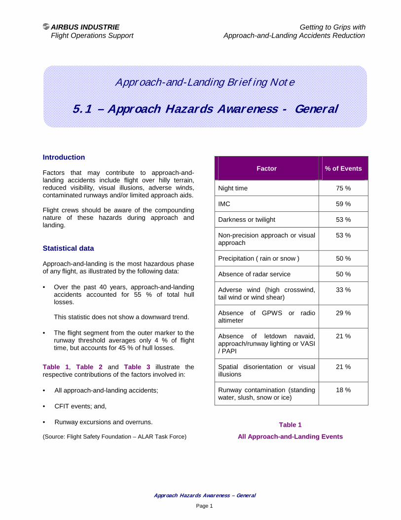
AIRBUS INDUSTRIE Getting to Grips with Flight Operations Support Approach-and-Landing Accidents Reduction
Approach Hazards Awareness – General
Page 1
Approach-and-Landing Briefing Note
5.1 – Approach Hazards Awareness - General
Introduction Factors that may contribute to approach-and-landing accidents include flight over hilly terrain, reduced visibility, visual illusions, adverse winds, contaminated runways and/or limited approach aids. Flight crews should be aware of the compounding nature of these hazards during approach and landing. Statistical data Approach-and-landing is the most hazardous phase of any flight, as illustrated by the following data:
• Over the past 40 years, approach-and-landing accidents accounted for 55 % of total hull losses. This statistic does not show a downward trend.
• The flight segment from the outer marker to the runway threshold averages only 4 % of flight time, but accounts for 45 % of hull losses.
Table 1, Table 2 and Table 3 illustrate the respective contributions of the factors involved in:
• All approach-and-landing accidents;
• CFIT events; and,
• Runway excursions and overruns. (Source: Flight Safety Foundation – ALAR Task Force)
Factor % of Events
Night time 75 %
IMC 59 %
Darkness or twilight 53 %
Non-precision approach or visual approach
53 %
Precipitation ( rain or snow ) 50 %
Absence of radar service 50 %
Adverse wind (high crosswind, tail wind or wind shear)
33 %
Absence of GPWS or radio altimeter
29 %
Absence of letdown navaid, approach/runway lighting or VASI / PAPI
21 %
Spatial disorientation or visual illusions
21 %
Runway contamination (standing water, slush, snow or ice)
18 %
Table 1
All Approach-and-Landing Events

AIRBUS INDUSTRIE Getting to Grips with Flight Operations Support Approach-and-Landing Accidents Reduction
Approach Hazards Awareness – General
Page 2
Factor % of Events
Low visibility 71 %
Hilly or mountainous terrain 67 %
Table 2
CFIT Events
Factor % of Events
Low visibility 73 %
Adverse wind conditions 67 %
Table 3
Runway Excursions and Overruns
Awareness Program Outline A company awareness program on approach-and-landing hazards should review and discuss the following factors that may contribute to approach-and-landing accidents.
When preparing and briefing an approach, these factors may be either:
• Known from the crew (by means of NOTAMs, dispatcher’s briefing, ATIS, etc) and, thus, may be briefed and accounted for; or,
• Unknown and, thus, be discovered as the approach-and-landing progresses
Aircraft Equipment
• Use (or absence) of the following safety-enhancing equipment:
− GPWS;
− TAWS;
− TCAS;
− Wind shear warning and guidance; and/or,
− Predictive windshear system.
Flight Crew
• Fatigue – reduced awareness:
− Long duty time:
! Long-haul operation; or,
! Short-haul or medium-haul / multiple-legs operation;
• Unfamiliar airport; and/or,
• Unfamiliar instrument or visual approach procedure.
Expected Approach
• Step-down non-precision approach or circling approach with no VASI / PAPI;
• Visual approach in darkness; and/or,
• Anticipated last-minute runway change. Approach Charts
• Absence of a published STAR;
• Missed-approach possible conflict with takeoff on intersecting runways; and/or,
• Incorrect or missing information. Airport Information Services
• Inaccurate TAF information;
• Absence of current weather reports;
• Absence of VOLMET;
• Absence of ATIS (or of English version of ATIS message); and/or,
• Inaccurate or outdated ATIS information (absence of regular ATIS update, when required).
Airport Air Traffic Control Services
• Absence or primary and/or secondary surveillance radar;
• Inadequate or ineffective radar vectoring practices;

AIRBUS INDUSTRIE Getting to Grips with Flight Operations Support Approach-and-Landing Accidents Reduction
Approach Hazards Awareness – General
Page 3
• Inadequate or non-standard air traffic control procedures;
• Inadequate air traffic flow management;
• Mixing of IFR and VFR traffics;
• Frequent uncontrolled VFR traffics in airport vicinity;
• Frequency congestion / controller overload caused by high density traffic or by a single controller operating tower and ground frequencies;
• Absence of adequate VHF coverage in known FIR or TMA sectors;
• Inadequate coordination between international and domestic FIRs;
• Absence of or failure to use landline communications between two close airports; and/or,
• Absence of English language proficiency in ATC communications and/or use of non-standard phraseology.
Airport Equipment
• Absence of / limited / low intensity approach and runway lighting (or part of it);
• Non-standard runway-edge lights spacing;
• Absence of ILS;
• ILS unusable beyond a specific point (because of obstacles) or below a specific altitude (because of approach over water);
• ILS without OM;
• ILS without VASI/PAPI to support the visual segment ;
• Offset VOR/DME approach;
• VOR/DME with inoperative DME;
• VOR incorrect calibration;
• NDB known as unreliable in adverse weather conditions;
• Non-precision or circling approach with absence of VASI / PAPI;
• VASI/PAPI being incorrectly calibrated or inoperative;
• Unsecured airport (i.e., absence of airport perimeter fences, allowing vehicles, persons or animals to access to runway or maneuvering areas);
• No illumination of wind sock or wind “T”; and/or,
• Faded painting of runway and/or taxiways markings.
Terrain
• Trees or man-made obstacles (antennas, ...) penetrating the obstacle clearance level;
• Topographical features requiring unusual procedures and reduced safety margins; and/or,
• Terrain features resulting in GPWS activation during approach.
Refer to Briefing Note 5.2 – Terrain Awareness for expanded information. Visual Illusions
• Airport environment (black hole, ...);
• Runway environment; and/or,
• Weather conditions. Refer to Briefing Note 5.3 – Visual Illusions Awareness for expanded information. Visibility
• Darkness, low visibility (rain, fog, mist, haze, low lighting, smoke).
Wind conditions
• Shifting or gusty wind, crosswind or tail wind; and/or,
• Known frequent wind shear on final approach of specific runway under adverse weather and / or wind conditions.
Refer to Briefing Note 5.4 – Wind Shear Awareness for expanded information.

AIRBUS INDUSTRIE Getting to Grips with Flight Operations Support Approach-and-Landing Accidents Reduction
Approach Hazards Awareness – General
Page 4
Runway condition
• Wet, but known as slippery-when-wet;
• Contaminated with standing water, slush, snow or ice;
• Heavy rubber deposit in touchdown zone;
• Reduced braking action;
• Insufficient water drainage or runway surface condition leaving water puddles after rain; and/or,
• Undulated surface in touchdown zone area. Taxiways
• Absence of high-speed-exit taxiways;
• Absence of parallel taxiway, thus requiring back track on the active runway; and/or,
• Non-standard taxiway marking and/or non-standard signs.
Low temperature operation
• Absence of a defined OAT threshold below which, a temperature correction on published altitudes is required.
Bird Strike Hazard
• Permanent or seasonal bird activity, without available bird control program and squad.
Decision-making and Countermeasures A company awareness program on approach-and-landing hazards should stress the following elements of effective crew coordination and decision-making:
• Comply with standard operating procedures (SOPs), published limitations, specific operational recommendations and flying techniques;
• Adjust and use the approach and go-around briefings to heighten the flight crew awareness of the specific hazards of the approach; and,
• Anticipate and be prepared for the worst case (i.e., “expecting the unexpected” by adopting a “What if ?” attitude);
Prepare options to counter approach-and-landing hazards, for example:
− Request a precision approach into the wind, whenever available;
− Define next targets and an approach gate that must be met for the approach to be continued;
− Wait for better conditions (fuel permitting); or,
− Divert to an airport with better weather conditions, wind conditions and/or runway conditions.
AIRBUS INDUSTRIE Getting to Grips with Flight Operations Support Approach-and-Landing Accidents Reduction
Approach Hazards Awareness – General
Page 5
Associated Briefing Notes Dedicated Briefing Notes provide specific and expanded information on the following approach hazards:
• 5.2 - Terrain Awareness,
• 5.3 - Visual Illusions Awareness,
• 5.4 - Windshear Awareness,
• 6.1 - Being Prepared to Go-around,
• 6.3 - Terrain Avoidance (Pullup) Maneuver.
Associated Documents The following documents published by the Flight Safety Foundation should be considered also when developing a company awareness program on approach-and-landing hazards:
• Approach and Landing Risk Awareness Tool/Checklist; and,
• Approach and Landing Risk Reduction Planning Guide.

AIRBUS INDUSTRIE Getting to Grips with Flight Operations Support Approach-and-Landing Accidents Reduction
Terrain Awareness – When and How ?
Page 1
Approach-and-Landing Briefing Note
5.2 – Terrain Awareness – When and How ?
Introduction Terrain awareness is defined as the combined awareness and knowledge of:
• Aircraft position;
• Aircraft altitude;
• Applicable minimum safe altitude (MSA);
• Terrain location and features; and,
• Other hazards.
When and how to build and maintain terrain awareness ? This Briefing Note provides a set of operational recommendations and training guidelines to establish and maintain the desired level of terrain awareness. Statistical data CFIT events account for approximately 45 % of approach-and-landing accidents but are the leading cause of fatalities. The absence of acquisition or the loss of visual references is the most common causal factor in CFIT accidents occurring during approach-and-landing; this includes:
• Descending below the MDA(H) or DA(H) without adequate visual references or with incorrect visual references (e.g., a lighted area in the airport vicinity, a taxiway or an other runway); or,
• Continuing the approach after the loss of visual references (e.g., visual references lost because of a fast moving rainshower or fog patch).
Factor % of Events
Low visibility 71 %
Hilly or mountainous terrain 67 %
Non-precision approach 57 %
Areas of flat terrain
( often on runway extended-centerline and within 15 nm of runway threshold )
29 %
Table 1
Terrain Factors in CFIT Events CFIT events during initial / intermediate approach or during final approach usually result from a premature descent below the initial-approach minimum-safe-altitude or below the minimum-descent-altitude (MDA). Navigation and Altitude Deviations When referring to terrain awareness, the following definitions need to be kept in mind. Navigation (course) deviation:
• Operation of an aircraft beyond the course clearance issued by ATC or beyond the defined airway system.
Altitude deviation:
• Deviation from the assigned altitude (or flight level) equal to or greater than 300 ft.
AIRBUS INDUSTRIE Getting to Grips with Flight Operations Support Approach-and-Landing Accidents Reduction
Terrain Awareness – When and How ?
Page 2
Inadequate terrain separation:
• Any operation with a terrain separation of less than 2000 ft in designated mountainous areas or less than 1000 ft in all other areas (except otherwise authorized and properly assigned by ATC in terminal areas).
Navigation ( course ) deviations and altitude deviations usually are caused by monitoring errors and may result in inadequate terrain separation. Monitoring errors involve the crew inability to monitor the aircraft trajectory and instruments while performing autopilot or FMS entries, or while being interrupted or distracted. Delayed recognition of monitoring errors is estimated to result in the following mean deviations from the intended vertical or lateral flight path:
• 1000 ft, in case of altitude deviation; and,
• 10 nautical miles, in case of course deviation. Terrain Awareness - When and How ? This paragraph provides an overview of:
• Opportunities available to enhance terrain awareness (e.g., operations manuals, technical training, navigation charts); and,
• Operational recommendations and techniques proposed to establish and maintain the desired level of terrain awareness.
This overview identifies the most important terrain-awareness-items (i.e., CFIT-critical item). Standard Operating Procedures Standard operating procedures (SOPs) should emphasize the following terrain-awareness-items:
• Task sharing and standard calls for effective cross check and backup, particularly for mode selections and target entries;
• Operations Golden Rules ( refer to Briefing Note 1.3 – Operations Golden Rules ):
The first golden rule states Fly, Navigate, Communicate and Manage, in that order.
Navigate can be defined by the following three “know where …” statements:
− Know where you are;
− Know where you should be; and,
− Know where the terrain and obstacles are.
• Approach and go-around briefings;
• Altimeter setting and cross-check procedures:
− When receiving an altitude clearance, immediately set the cleared altitude in the FCU altitude window (even before readback, if appropriate because of workload);
− Ensure that selected altitude is cross-checked by both crewmembers;
− Ensure that the cleared altitude is above the applicable minimum safe altitude; and,
− Positively confirm any altitude clearance below the MSA, when under radar vectoring (or be aware of applicable minimum vectoring altitude for the sector).
• Descent profile management;
• Energy management;
• Terrain awareness;
• Approach hazards awareness;
• Elements of a stabilized approach and approach gates;
• Readiness and commitment to respond to a GPWS / TAWS alert; and,

AIRBUS INDUSTRIE Getting to Grips with Flight Operations Support Approach-and-Landing Accidents Reduction
Terrain Awareness – When and How ?
Page 3
• Use of radio altimeter:
The setting of the baro-altimeter bug and radio-altimeter DH should be in line with the applicable SOPs. The following typical summary is based on the use of QNH for altimeter setting.
Baro Bug RA DH
Visual MDA/DA of instrument approach
or
200 ft AAL
200 ft
Note 1
Non-ILS MDA 200 ft
Note 1
ILS CAT I
No RA
DA
200 ft
Note 1
ILS CAT I RA
ILS CAT II
DA
Note 2
RA DH
ILS CAT III
with DH
DA
Note 2
RA DH
ILS CAT III
no DH
TDZ altitude
Table 1
Setting of Baro Altimeter Bug and Radio Altimeter DH Note 1 :
The RA DH can be set (e.g., at 200 ft), for terrain awareness purposes. In this case, the use of the radio altimeter should be discussed during the approach briefing.
For all approaches, except CAT I with RA, CAT II and CAT III ILS approaches, the approach MINIMUM callout will be based on the baro-altimeter bug set at the MDA(H) or the DA(H).
Note 2 :
CAT II DA or CAT I DA can be set in readiness for a reversion to CAT I minima.
Radio altimeter callouts can be either:
− called (verbalized) by the PNF or the flight engineer; or,
− automatically generated by a synthesized voice.
Callouts should be tailored to the airline operating policy and to the type of approach. To enhance the flight crew’s terrain awareness, a callout Radio Altimeter Alive, should be announced by the first crewmember observing the radio altimeter activation at 2500 ft AGL. The RA reading should be included in the instrument scan for the remainder of the approach.
Training Altitude Awareness Program: The implementation of an altitude awareness program by several airlines has reduced significantly the number of altitude deviations. An altitude awareness program can be developed based on the contents of the Briefing Notes 3.1 Altimeter Setting – Use of Radio Altimeter and 3.2 – Altitude Deviations. The altitude awareness program should emphasize the following aspects:
• Awareness of altimeter setting errors, e.g.:
− 29.XX in.hg versus 28.XX or 30.XX in.hg; or,
− 29.XX in.hg versus 9XX hPa.
• Awareness of altitude corrections for low OAT operations and awareness of pilot’s and/or controller’s responsibility in applying these corrections.
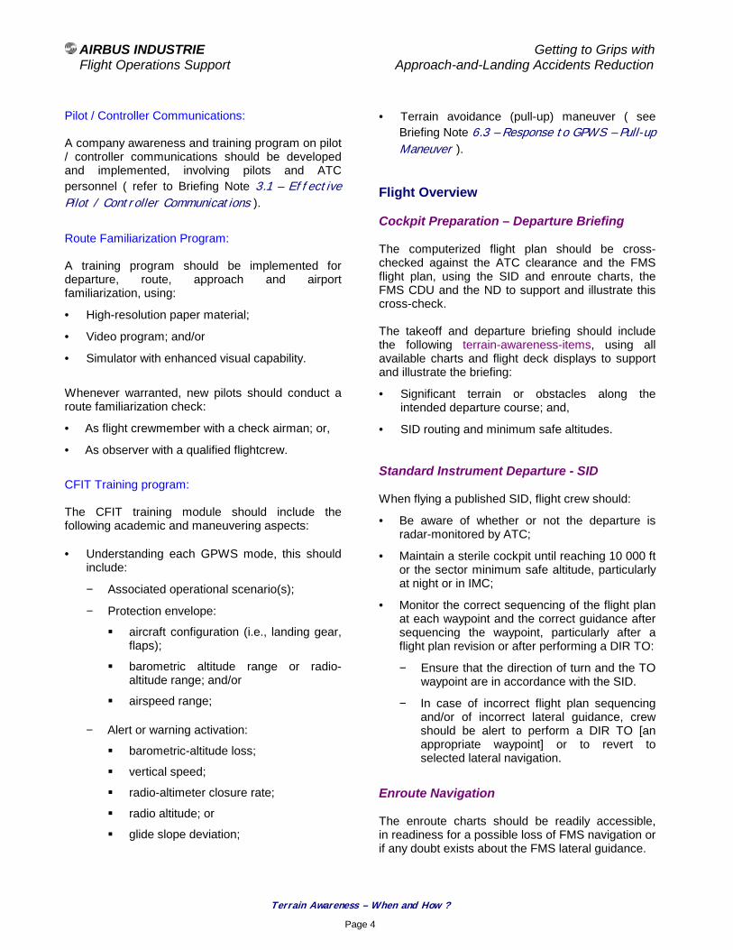
AIRBUS INDUSTRIE Getting to Grips with Flight Operations Support Approach-and-Landing Accidents Reduction
Terrain Awareness – When and How ?
Page 4
Pilot / Controller Communications: A company awareness and training program on pilot / controller communications should be developed and implemented, involving pilots and ATC personnel ( refer to Briefing Note 3.1 – Effective Pilot / Controller Communications ). Route Familiarization Program: A training program should be implemented for departure, route, approach and airport familiarization, using:
• High-resolution paper material;
• Video program; and/or
• Simulator with enhanced visual capability.
Whenever warranted, new pilots should conduct a route familiarization check:
• As flight crewmember with a check airman; or,
• As observer with a qualified flightcrew.
CFIT Training program: The CFIT training module should include the following academic and maneuvering aspects: • Understanding each GPWS mode, this should
include:
− Associated operational scenario(s);
− Protection envelope:
! aircraft configuration (i.e., landing gear, flaps);
! barometric altitude range or radio-altitude range; and/or
! airspeed range;
− Alert or warning activation:
! barometric-altitude loss;
! vertical speed;
! radio-altimeter closure rate;
! radio altitude; or
! glide slope deviation;
• Terrain avoidance (pull-up) maneuver ( see Briefing Note 6.3 – Response to GPWS – Pull-up Maneuver ).
Flight Overview Cockpit Preparation – Departure Briefing The computerized flight plan should be cross-checked against the ATC clearance and the FMS flight plan, using the SID and enroute charts, the FMS CDU and the ND to support and illustrate this cross-check. The takeoff and departure briefing should include the following terrain-awareness-items, using all available charts and flight deck displays to support and illustrate the briefing:
• Significant terrain or obstacles along the intended departure course; and,
• SID routing and minimum safe altitudes. Standard Instrument Departure - SID When flying a published SID, flight crew should:
• Be aware of whether or not the departure is radar-monitored by ATC;
• Maintain a sterile cockpit until reaching 10 000 ft or the sector minimum safe altitude, particularly at night or in IMC;
• Monitor the correct sequencing of the flight plan at each waypoint and the correct guidance after sequencing the waypoint, particularly after a flight plan revision or after performing a DIR TO:
− Ensure that the direction of turn and the TO waypoint are in accordance with the SID.
− In case of incorrect flight plan sequencing and/or of incorrect lateral guidance, crew should be alert to perform a DIR TO [an appropriate waypoint] or to revert to selected lateral navigation.
Enroute Navigation The enroute charts should be readily accessible, in readiness for a possible loss of FMS navigation or if any doubt exists about the FMS lateral guidance.

AIRBUS INDUSTRIE Getting to Grips with Flight Operations Support Approach-and-Landing Accidents Reduction
Terrain Awareness – When and How ?
Page 5
Flight Progress Monitoring During climb, cruise and descent, flight crew should:
• Monitor FMS guidance and navigation accuracy;
• Monitor instruments and navaids raw data (as applicable);
• Use all available information (i.e., cockpit displays, navaids raw data and charts); and,
• Request confirmation or clarification from ATC if any doubt exists about terrain clearance, particularly when being radar vectored.
Descent Preparation – Approach and Go-around Briefing A thorough briefing should be performed regardless of:
• How familiar the destination airport and the approach may be; or,
• How often the crewmembers have flown together.
The briefing should help the PF (giving the briefing) and the PNF (receiving and acknowledging the briefing) to reach and share a common mental model of the approach. In hilly or mountainous areas, the briefing should include the following terrain-awareness-items:
• Descent profile and descent management;
• Terrain features;
• Energy management (i.e., deceleration and configuration management); and,
• Other approach hazards (e.g., black hole).
The flight management system (FMS) operational pages and the ND should be used to guide and illustrate the briefing, and to confirm the various data entries. An expanded review of the terrain-awareness-items to be included in the approach briefing – as practical and appropriate for the conditions of the flight – is provided hereafter.
ATIS: Review and discuss the following items:
• Runway in use (type of approach);
• Expected arrival route ( STAR - or radar vectors);
• Altimeter setting (QNH or QFE, as required); and,
• Transition level (unless standard for the country or for the airport).
Approach Chart: Review and discuss the following terrain-awareness-items using the approach chart and the FMS/ND (as applicable):
• Designated runway and approach type;
• Chart index number and date;
• Minimum Safety Altitude (MSA) - reference point, sectors and altitudes;
• Let-down navaid frequency and identification (confirm the correct navaid setup);
• Airport elevation;
• Approach transitions (fixes, holding pattern, altitude and speed constraints/restrictions, required navaids setup);
• Initial approach fix (IAF) and intermediate approach fix (IF), as applicable (positions and crossing altitudes);
• Final approach course (and lead-in radial);
• Terrain features (location and elevation of hazardous terrain or man-made obstacles);
• Approach profile view :
- Final approach fix (FAF);
- Final descent point (if different from FAF);
- Visual descent/decision point (VDP);
- Missed-approach point (MAP);
- Typical vertical speed at expected final approach ground speed (GS); and,
- Touchdown zone elevation (TDZE).

AIRBUS INDUSTRIE Getting to Grips with Flight Operations Support Approach-and-Landing Accidents Reduction
Terrain Awareness – When and How ?
Page 6
• Missed approach :
- Lateral and vertical navigation; and,
- Significant terrain or obstacles.
Low OAT Operation When operating with a low OAT, temperature corrections on the indicated altitude need to be applied to all the following published altitudes:
• MEA, MSA;
• Transition routes altitude;
• Procedure turn altitude (as applicable);
• FAF altitude;
• Step-down altitude(s) and MDA(H) during a non-ILS approach;
• OM crossing altitude during an ILS approach; and,
• Waypoints crossing altitudes, during a GPS approach flown with barometric vertical navigation.
In a standard atmosphere, the indicated altitude reflects the true altitude above the mean sea level (MSL) and therefore provides a reliable indication of terrain separation. When OAT is significantly warmer or colder than the standard temperature, the indicated altitude is higher or lower than the true altitude (as illustrated by Figure 1.
In low temperature, the true altitude is lower than the indicated altitude, resulting in a lower-than-anticipated terrain separation and in a possible terrain clearance hazard (as illustrated by Figure 1, for a – 40 degree Celsius OAT).
Figure 1
Effect of OAT on True Altitude Flying into low temperature has the same effect as flying into a low-pressure area; the aircraft is lower than the altimeter indicates. These effects are summarized and illustrated in Table 2, featuring a well-known aviation golden rule:
From To
Atmospheric Pressure
High Low
OAT Warm Cold
Look out
below
Table 2
Atmospheric Pressure and Temperature Effects on True Altitude
Given Atmospheric Pressure( pressure altitude )
True Altitude
Low OATHigh OAT
IndicatedAltitude
2000 ft3000 ft
2000 ft
1000 ft
Standard OAT
1600 ft

AIRBUS INDUSTRIE Getting to Grips with Flight Operations Support Approach-and-Landing Accidents Reduction
Terrain Awareness – When and How ?
Page 7
Airport charts: Review and discuss the following terrain-awareness-items using the airport charts: • Approach and runway lighting, and other
expected visual references; and,
• Specific hazards (such as man-made obstacles, as applicable).
If another airport is located in the close vicinity of the destination airport, relevant details or procedures should be discussed for awareness purposes.
Use of automation: Discuss the intended use of automation for vertical and lateral navigation:
• Use of FMS-managed guidance or selected modes; and,
• Use of precision approach, constant-angle or step-down non-precision approach, as required.
Descent Management and Monitoring Before entering the terminal area (TMA), check the FMS navigation accuracy (using navaids raw data) against the applicable criteria for terminal or approach navigation. If the accuracy criteria for lateral FMS navigation in terminal area and/or for approach are not met, revert to a selected lateral mode with ND in ROSE or ARC mode. If flying with IRS ONLY navigation, do not descend below the sector MSA without positive confirmation of the aircraft position, using navaids raw data. Standard Arrival - STAR Be aware of whether or not the arrival is radar-monitored by the ATC. Maintaining a sterile cockpit when below 10 000 ft or below the sector minimum safe altitude (MSA), particularly at night or in instrument meteorological conditions (IMC).
Monitor the correct sequencing of the flight plan at each waypoint and the correct guidance after sequencing the waypoint, particularly after a flight plan revision or after performing a DIR TO:
• Ensure that the direction-of-turn and the TO waypoint are in accordance with the SID.
• In case of incorrect flight plan sequencing and/or of incorrect lateral guidance, crew should be alert to perform a DIR TO [an appropriate waypoint] or to revert to selected lateral navigation.
Changes in clearances should be fully understood before being accepted and implemented. For example, being cleared to a lower altitude should never be understood as a clearance to descend (prematurely) below the charted sector or segment minimum safe altitude. When being radar vectored, make sure that :
• The controller has clearly identified your radar return by stating “radar contact”;
• The controller can read obstacle clearance altitudes on his or her radar scope (awareness of minimum vectoring altitude and responsibility for terrain separation);
• The controller does not forget that you are on a radar vector, heading toward high or rising terrain;
• The pilot / controller two-way communication remain effective at all times;
• You maintain your own vertical and horizontal situational awareness; and,
• You request confirmation or clarification from ATC without delay and in clear terms, in case of any doubt.
To prevent an excessive terrain-closure-rate, consider a maximum vertical speed and reduce this maximum limit with decreasing altitude (e.g., do not exceed – 2000 ft/mn when below 2000 ft AGL and – 1000 ft/mn when below 1000 ft AGL). During the final approach segment, the primary attention of PF and PNF pilots should be directed to any required altitude constraint or altitude / distance check prior to reaching the MDA(H) or DA(H).
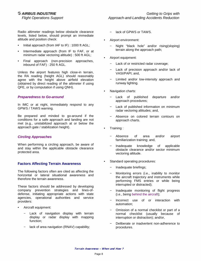
AIRBUS INDUSTRIE Getting to Grips with Flight Operations Support Approach-and-Landing Accidents Reduction
Terrain Awareness – When and How ?
Page 8
Radio altimeter readings below obstacle clearance levels, listed below, should prompt an immediate altitude and position check:
• Initial approach (from IAF to IF) : 1000 ft AGL;
• Intermediate approach (from IF to FAF, or at minimum radar vectoring altitude) : 500 ft AGL;
• Final approach (non-precision approaches, inbound of FAF) : 250 ft AGL.
Unless the airport features high close-in terrain, the RA reading (height AGL) should reasonably agree with the height above airfield elevation (obtained by direct reading of the altimeter if using QFE, or by computation if using QNH).
Preparedness to Go-around In IMC or at night, immediately respond to any GPWS / TAWS warning. Be prepared and minded to go-around if the conditions for a safe approach and landing are not met (e.g., unstabilized approach at or below the approach gate / stabilization height).
Circling Approaches When performing a circling approach, be aware of and stay within the applicable obstacle clearance protected area. Factors Affecting Terrain Awareness The following factors often are cited as affecting the horizontal or lateral situational awareness and therefore the terrain awareness. These factors should be addressed by developing company prevention strategies and lines-of-defense, initiating appropriate actions with state agencies, operational authorities and service providers:
• Aircraft equipment:
− Lack of navigation display with terrain display or radar display with mapping function;
− lack of area navigation (RNAV) capability;
− lack of GPWS or TAWS.
• Airport environment:
− Night “black hole” and/or rising(sloping) terrain along the approach path;
• Airport equipment:
− Lack of or restricted radar coverage;
− Lack of precision approach and/or lack of VASI/PAPI; and,
− Limited and/or low-intensity approach and runway lighting.
• Navigation charts:
− Lack of published departure and/or approach procedures;
− Lack of published information on minimum radar vectoring altitudes; and,
− Absence on colored terrain contours on approach charts.
• Training :
− Absence of area and/or airport familiarization training; and,
− Inadequate knowledge of applicable obstacle clearance and/or sector minimum vectoring altitude.
• Standard operating procedures:
− Inadequate briefings;
− Monitoring errors (i.e., inability to monitor the aircraft trajectory and instruments while performing FMS entries or while being interrupted or distracted);
− Inadequate monitoring of flight progress (i.e., being behind the aircraft);
− Incorrect use of or interaction with automation;
− Omission of a normal checklist or part of a normal checklist (usually because of interruption or distraction); and/or,
− Deliberate or inadvertent non-adherence to procedures.

AIRBUS INDUSTRIE Getting to Grips with Flight Operations Support Approach-and-Landing Accidents Reduction
Terrain Awareness – When and How ?
Page 9
• Pilot/Controller Communications:
− Omission of position report at first radio contact in an area without radar coverage (i.e., reducing the controller’s situational awareness);
− Breakdown in pilot / controller or intra-crew communications (e.g., readback/hearback errors, failure to resolve doubts or ambiguities, use of non-standard phraseology); and/or,
− Accepting an amended clearance without prior evaluation.
• Human Factors and CRM:
− Incorrect CRM practices (absence of crosscheck and back-up for AP mode selections and AP/FMS data entries, late recognition of monitoring errors);
− Inadequate decision-making;
− Failure to resolve a doubt or confusion;
− Fatigue;
− Complacency;
− Spatial disorientation; and/or,
− Visual illusions. Summary of key points The following key points and recommendations should be used in the development of company prevention strategies and actions enhancing terrain awareness. Approach Charts Providing flight crews with departure and approach charts featuring terrain with color shaded contours. Altimeter setting Promoting strict adherence to adequate SOPs to reduce altimeter-setting errors and for optimum use of baro-altimeter bug and radio-altimeter DH.
To reduce altimeter-setting errors, flight crew should:
• Be aware of altimeter setting changes due to prevailing weather conditions (e.g., extreme cold or warm fronts, steep frontal surfaces, semi-permanent or seasonal low pressure areas);
• Be aware of the altimeter setting unit in use at the destination airport;
• Be aware of the anticipated altimeter setting, using two independent sources for cross-check (e.g., METAR and ATIS messages);
• Ensure effective cross-check and back-up;
• Adhere to SOPs for:
− reset of altimeters in climb and descent (per FCOM or per company’ SOPs);
− use of standby altimeter to cross-check main altimeters;
− altitude callouts;
− RA callouts; and,
− setting of baro-altimeter bug and RA DH.
• Cross-check that the cleared / assigned altitude is above the sector minimum safe altitude (unless crew is aware of applicable minimum vectoring altitude for the sector).
Flight progress monitoring Flight monitoring for terrain awareness includes:
• Monitoring FMS guidance and FMS navigation accuracy;
• Monitoring instruments and navaids raw data;
• Using all available information available (i.e., cockpit displays, navaids raw data and charts); and,
• Requesting confirmation or clarification from ATC if any doubt exists about terrain clearance, particularly when being radar vectored.
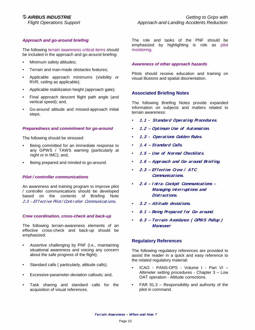
AIRBUS INDUSTRIE Getting to Grips with Flight Operations Support Approach-and-Landing Accidents Reduction
Terrain Awareness – When and How ?
Page 10
Approach and go-around briefing The following terrain awareness critical items should be included in the approach and go-around briefing:
• Minimum safety altitudes;
• Terrain and man-made obstacles features;
• Applicable approach minimums (visibility or RVR, ceiling as applicable);
• Applicable stabilization height (approach gate);
• Final approach descent flight path angle (and vertical speed); and,
• Go-around altitude and missed-approach initial steps.
Preparedness and commitment for go-around The following should be stressed:
• Being committed for an immediate response to any GPWS / TAWS warning (particularly at night or in IMC); and,
• Being prepared and minded to go-around. Pilot / controller communications An awareness and training program to improve pilot / controller communications should be developed based on the contents of Briefing Note 2.3 – Effective Pilot/Controller Communications. Crew coordination, cross-check and back-up The following terrain-awareness elements of an effective cross-check and back-up should be emphasized:
• Assertive challenging by PNF (i.e., maintaining situational awareness and voicing any concern about the safe progress of the flight);
• Standard calls ( particularly, altitude calls);
• Excessive-parameter-deviation callouts; and,
• Task sharing and standard calls for the acquisition of visual references.
The role and tasks of the PNF should be emphasized by highlighting is role as pilot monitoring. Awareness of other approach hazards Pilots should receive education and training on visual illusions and spatial disorientation. Associated Briefing Notes The following Briefing Notes provide expanded information on subjects and matters related to terrain awareness:
• 1.1 - Standard Operating Procedures.
• 1.2 – Optimum Use of Automation.
• 1.3 - Operations Golden Rules.
• 1.4 – Standard Calls.
• 1.5 – Use of Normal Checklists.
• 1.6 – Approach and Go-around Briefing.
• 2.3 – Effective Crew / ATC Communications.
• 2.4 – Intra-Cockpit Communications – Managing interruptions and Distractions.
• 3.2 – Altitude deviations.
• 6.1 – Being Prepared for Go-around.
• 6.3 – Terrain-Avoidance ( GPWS Pullup ) Maneuver
Regulatory References The following regulatory references are provided to assist the reader in a quick and easy reference to the related regulatory material:
• ICAO - PANS-OPS - Volume I - Part VI – Altimeter setting procedures - Chapter 3 – Low OAT operation - Altitude corrections.
• FAR 91.3 – Responsibility and authority of the pilot in command.
AIRBUS INDUSTRIE Getting to Grips with Flight Operations Support Approach-and-Landing Accidents Reduction
Terrain Awareness – When and How ?
Page 11
• FAR 91.119 – Minimum safe altitudes: General.
• FAR 91.121 – Altimeter settings.
• FAR 91.123 – Compliance with ATC clearances and instructions.
• FAR 91.155 – Basic VFR weather minimums.
• FAR 91.157 – Special VFR weather minimums.
• FAR 91.175 – Takeoff and landing under IFR.
• FAR 91.185 – IFR operations: Two-way communications failure.
• FAR 97 – Standard Instrument Approach Procedures – Terminal Instrument Approach Procedures (TERPS).
• FAR 121.97 or 121.117 – Airports: Required data.
• FAR 121.135 – Manual Requirements – Operations Manual – Contents.
• FAR 121.315 – Cockpit check procedure.
• FAR 121.360 – Ground proximity warning – glide slope deviation alerting system.
• FAR 121.443 and 121.445 – Route, Special areas and airports qualification for pilot in command (PIC).
• FAR 121.542 – Flight crewmember duties (sterile cockpit rule).
Other References The following Flight Safety Foundation references can be used to further illustrate and complement the information contained in this Briefing Note:
• CFIT Education and Training Aid.
• CFIT Checklist – Evaluate the Risk and Take Action.
• ALAR Risk Awareness Tool/Checklist.
• ALAR Risk Reduction Planning Guide.
• Flight Safety Digest – Killers in Aviation – Nov.98-Feb.99.
Photo credit : TAKEOFF The Swiss Professional Pilots’ Association Magazine
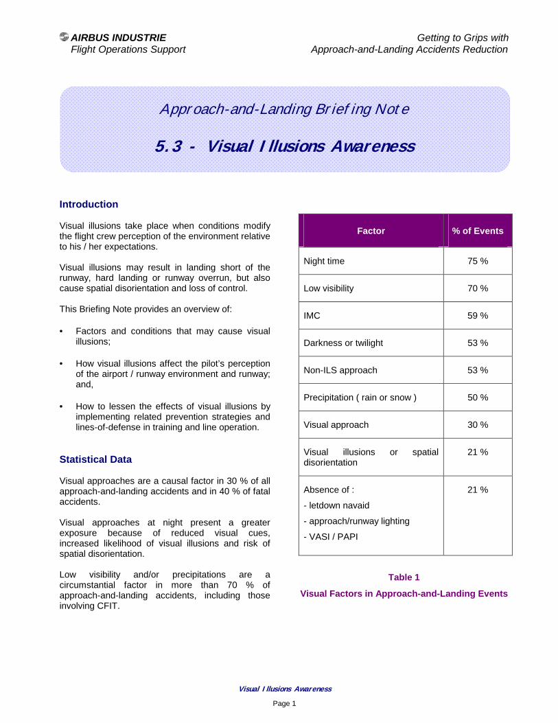
AIRBUS INDUSTRIE Getting to Grips with Flight Operations Support Approach-and-Landing Accidents Reduction
Visual Illusions Awareness
Page 1
Approach-and-Landing Briefing Note
5.3 - Visual Illusions Awareness
Introduction Visual illusions take place when conditions modify the flight crew perception of the environment relative to his / her expectations. Visual illusions may result in landing short of the runway, hard landing or runway overrun, but also cause spatial disorientation and loss of control. This Briefing Note provides an overview of:
• Factors and conditions that may cause visual illusions;
• How visual illusions affect the pilot’s perception of the airport / runway environment and runway; and,
• How to lessen the effects of visual illusions by implementing related prevention strategies and lines-of-defense in training and line operation.
Statistical Data Visual approaches are a causal factor in 30 % of all approach-and-landing accidents and in 40 % of fatal accidents. Visual approaches at night present a greater exposure because of reduced visual cues, increased likelihood of visual illusions and risk of spatial disorientation. Low visibility and/or precipitations are a circumstantial factor in more than 70 % of approach-and-landing accidents, including those involving CFIT.
Factor % of Events
Night time 75 %
Low visibility 70 %
IMC 59 %
Darkness or twilight 53 %
Non-ILS approach 53 %
Precipitation ( rain or snow ) 50 %
Visual approach 30 %
Visual illusions or spatial disorientation
21 %
Absence of :
- letdown navaid
- approach/runway lighting
- VASI / PAPI
21 %
Table 1
Visual Factors in Approach-and-Landing Events

AIRBUS INDUSTRIE Getting to Grips with Flight Operations Support Approach-and-Landing Accidents Reduction
Visual Illusions Awareness
Page 2
Visual Illusions – Factors and Conditions The following factors and conditions affect the flight crew ability to accurately perceive the environment, resulting in visual illusions.
Airport environment:
• Ground texture and features;
• Off-airport light patterns such as brightly lighted parking lots or streets;
• “Black hole” along the final approach flight path; and/or,
• Uphill or downhill sloping terrain before the runway threshold or in the approach path environment.
Runway environment:
• Runway dimensions (aspect ratio);
• Runway uphill or downhill slope;
• Terrain drop-off at the approach end of the runway;
• Approach and runway lighting; and/or,
• Runway condition (e.g., wet runway).
Weather conditions:
• Ceiling;
• Visibility (i.e., vertical visibility, slant visibility and horizontal visibility); and/or,
• Cloudiness (e.g., rain, fog or fog patches, haze, mist, smoke, snow, whiteout effect).
How do Visual Illusions Affect the Pilot’s Perception ? Visual illusions result from the absence of or the alteration of visual references that modifies the pilot perception of his / her position relative to the runway threshold.
Visual illusions affect perception of heights, distances and/or intercept angles. Visual illusions are most critical when transitioning from IMC and instrument references to VMC and visual references. Visual illusions (such as the black-hole effect) affect the flight crew vertical and horizontal situational awareness, particularly during the base leg and when turning final (as applicable) and during the final approach. Visual illusions usually induce crew inputs (corrections) that cause the aircraft to deviate from the original and intended vertical or lateral flight path. Visual illusions can affect the decision about when and how fast to descend from the MDA(H). The following paragraph provides an expanded overview of all the factors and conditions creating visual illusions to discuss how each factor or condition may affect the pilot perception of:
• The airport and runway environment;
• The terrain separation; and,
• The aircraft vertical or lateral deviation from the intended flight-path.
Usually, more than one factor is involved in a given approach, compounding the individual effects. Airport environment:
• “Black hole” along the final approach flight path:
− In case of approach over water or with an unlighted area on the approach path, the absence of visible ground features reduces the crew ability to perceive the aircraft lateral position and vertical position relative to the intended flight path.

AIRBUS INDUSTRIE Getting to Grips with Flight Operations Support Approach-and-Landing Accidents Reduction
Visual Illusions Awareness
Page 3
• Uphill or downhill terrain before the runway threshold:
− An uphill slope in the approach zone or a drop-off of terrain at the approach end of the runway creates an illusion of being too high (i.e., impression of a steep glide path, as shown on Figure 1), thus:
! possibly inducing a correction (increasing the rate of descent) that places the aircraft below the intended glide path; or,
! preventing the flight crew from detecting a too shallow flight path.
Figure 1
− A downhill slope in the approach zone creates an illusion of being too low (i.e., impression of a shallow glide path, as shown on Figure 2), thus:
! possibly inducing a correction placing the aircraft above the intended glide path; or,
! preventing the flight crew from detecting a too steep flight path.
Figure 2
Runway environment:
• Runway dimensions / aspect ratio (Figure 3):
− the runway aspect ratio (i.e., its length relative to its width) affects the crew visual perspective view of the runway:
! a large or short runway (low aspect ratio) creates an impression of being too low; and,
! a narrow or long runway (high aspect ratio) creates an impression of being too high.
Figure 3
Photo - LFBO 15 R ( 3500 m x 45 m ) 3-degree glide slope / 200 ft RA
• Runway uphill or downhill slope:
− An uphill slope creates an illusion of being too high (impression of a steep glide path); and,
− A downhill slope creates an illusion of being too low (impression of a shallow glide path).
• Approach and runway lighting:
− The approach and runway lighting (including the touchdown zone lighting ) affects the dept perception as a function of:
! The lighting intensity;
! The daytime or night time conditions; and,
! The weather conditions.
Actual Glide Path
Perceived Glide Path
Actual Glide Path
Perceived Glide Path
AIRBUS INDUSTRIE Getting to Grips with Flight Operations Support Approach-and-Landing Accidents Reduction
Visual Illusions Awareness
Page 4
− Bright runway-lights create the impression of being closer to the runway (hence on a steeper glide path);
− Low intensity lights create the impression of being farther away (hence on a shallower glide path);
− A non-standard spacing of runway lights also modifies the pilot’s perception of the runway distance and glide path; and,
− If runway lighting is partially visible (e.g., during the downwind leg or during the base leg of a visual or circling approach), the runway may appear being farther away or at a different angle (i.e., the intercept angle is perceived as smaller than actual).
Runway approach aids: The following runway approach-aids and conditions may increase the crew exposure to visual illusions:
• Glide slope beam being unusable beyond a specific point because of terrain or below a specific altitude/height because of approach over water;
• Offset localizer course; and/or,
• 2-bar VASI, if used below (typically) 300 ft height above touchdown (HAT) for glide path corrections.
Weather conditions: The following weather conditions may cause visual illusions:
• Precipitation’s (e.g., rain, fog, snow):
− Flying in light rain, fog , haze, mist, smoke, dust, glare or darkness usually create an illusion of being too high;
− Flying in haze creates the impression that the runway is farther away, inducing a tendency to shallow the glide path and land long;
− Shallow fog (i.e., fog layer not exceeding 300 ft in thickness) results in a low obscuration but also in low horizontal visibility:
! When on top of a shallow fog layer, the ground (or airport and runway, if flying overhead) can be seen, but when entering the fog layer the forward and slant visibility usually are lost;
! Entering a fog layer also creates the perception of a pitch up, thus inducing a tendency to push over and place the aircraft below the desired glide path and in a steeper-than-desired attitude;
− In light rain or moderate rain, the runway may also appear fuzzy because of rain halo effect, increasing the risk of not perceiving a vertical deviation or lateral deviation during the visual segment.
The visual segment is defined as the segment flown after full transition from instruments to visual references;
− heavy rain affects depth perception and distance perception:
! Rain on windshields creates a refraction and the perception of being too high, thus inducing a nose down correction that places the aircraft below the desired flight path;
! In daylight conditions, rain diminishes the apparent intensity of the approach lighting system (ALS) resulting in the runway appearing to be farther away;
As a result of this illusion, the flightcrew tends to shallow the flight path resulting in a long landing;
! In night time conditions, rain increases the apparent brilliance of the ALS, making the runway appears to be closer, inducing a pitch down input and the risk of landing short of the runway threshold.

AIRBUS INDUSTRIE Getting to Grips with Flight Operations Support Approach-and-Landing Accidents Reduction
Visual Illusions Awareness
Page 5
− when breaking out of the overcast at both ceiling and visibility minimums (DH and RVR), the slant visibility may not allow sight of the farther bar(s) of the VASI/PAPI, thus reducing the available visual clues for the visual segment in reduced visibility;
− a snow-covered terrain together with a clouds overcast create a phenomenon called “white-out” that eliminate perception of terrain features (slope) and height above terrain.
• Crosswind:
− In crosswind conditions, the runway lights and environment will be angled with the aircraft heading; flight crew should maintain the drift correction and resist the tendency to align the aircraft heading with the runway centerline.
• Runway surface condition (e.g., wet runway):
− A wet runway does not reflect light, thus affecting depth perception by appearing to be farther away.
This visual effect usually results in a late flare and in a firm touchdown. When landing on a wet runway, peripheral vision of runway edge lights should be used to increase the depth perception and determine the flare point.
The following table provides a summary of the various factors and conditions together with their effects on the pilot’s perception and actions:
Condition Perception Action Result
Narrow or
long runway
Runway or terrain
uphill slope
Being too high
Push
Land short / land hard
Wide or
short runway
Runway or terrain
downhill slope
Being too low
Pull
Land long / overrun
Pitch down or
Duck under
- - Land short / land hard /
CFIT
Bright runway lighting
Being too close
(too steep)
Push Land short / land hard
Low intensity lighting
Being farther away
(too shallow)
Pull Land long / overrun
Light rain, fog, haze,
mist smoke, dust
Being too high
Push Land short / land hard
Entering fog(shallow
layer)
Being pitch up
Push over
Steep glide path /
( CFIT )
Flying in haze
Being farther away (too shallow)
Pull Land long / overrun
Wet Runway Being farther away (too
high)
Late flare
Hard landing
Crosswind Being angled with
runway
Cancel drift
correction
Drifting off track / off runway centerline

AIRBUS INDUSTRIE Getting to Grips with Flight Operations Support Approach-and-Landing Accidents Reduction
Visual Illusions Awareness
Page 6
How to Lessen the Effects of Visual Illusions ? To lessen the effects of visual illusions, prevention strategies and lines-of-defense should be developed and implemented based on the following recommendations.
Hazard Awareness Operators should assess their exposure to visual illusions in their operating environment (i.e., over the entire route network). Flight crews should be educated and trained on the factors and conditions creating visual illusions and their effects on the perception of the environment and aircraft position:
• Perception of heights / depth, distances, and angles;
• Assessment of aircraft lateral position and glide path.
The awareness of visual illusions can be supported by an identification of all hazard-airports and/or hazard-runways (in the operator’s network) as a function of the available navaids, visual aids and prevailing hazards.
Hazard Assessment Approach hazards should be assessed for each individual approach, during the approach and go-around briefing, by reviewing the following elements:
• Ceiling and visibility conditions;
• Weather:
− wind, turbulence;
− rain showers; and/or,
− fog or smoke patches;
• Crew experience with airport and airport environment:
− surrounding terrain; and/or,
− specific airport and runway hazards (obstructions, black-hole, off-airport light patterns, …);
• Runway approach and visual aids:
− Type of approach (let-down aid restriction, such as glide slope unusable beyond a specific point or below a specific altitude);
− Type of approach lighting system; and,
− VASI or PAPI availability.
Terrain awareness When requesting or accepting a visual approach, flight crew should be aware of the surrounding terrain features and man-made obstacles. At night, an unlighted hillside between a lighted area and the runway threshold may prevent the flight crew from correctly perceiving the rising terrain. Flying techniques Type of approach At night, when an instrument approach is available, prefer this approach to a visual approach to reduce the risk of accident caused by visual illusions:
• ILS approach, with use of VASI / PAPI (as available) for the visual segment; or,
• Non-precision approach, supported by a VASI / PAPI (as available).
On a non-precision approach, do not descend below the MDA(H) before reaching the visual descent/decision point (VDP), even if adequate visual references have been acquired before reaching the VDP. To prevent going too early to visual references and descending prematurely below the MDA(H), the PF should maintain reference to instruments until reaching the VDP. This provides further protection against visual illusions in hazard conditions. During a visual or circling approach, if the VASI / PAPI indicates below glide slope level off or climb until the VASI/PAPI shows on-glide-path.

AIRBUS INDUSTRIE Getting to Grips with Flight Operations Support Approach-and-Landing Accidents Reduction
Visual Illusions Awareness
Page 7
Flight path monitoring Resist the tendency to pitch down and “duck under”; this is the greatest challenge during the visual segment of the approach, this includes:
• Pitching down into the approach light in an attempt to see the runway during a precision approach; or,
• Ducking under because of the impression of being too high when affected by visual illusions.
Maintain a combination of visual flying supported by monitoring of instruments (including the glide slope deviation during the visual segment of an ILS approach). Monitor the VASI/PAPI, whenever available; this provides additional visual cues to resist the tendency to increase or decrease the rate of descent. On runways equipped with an ALSF-II approach lighting system, be aware of the two rows of red lights aligned with the touchdown zone lights as an additional safeguard against “ducking under”. The following provides a summary of the techniques available to counter visual illusions (and prevent from ducking under):
• Maintain instruments scan down to touchdown;
• Cross-check instrument indications against outside visual cues to confirm glide path;
• Use an ILS approach, whenever available; and,
• Use VASI / PAPI, if available, down to runway threshold (only when using a 3-bar VASI or a PAPI)
• Use available references and indications such as the ND extended runway centerline, the ILS-DME (or VOR-DME) distance and the altitude above airfield elevation to confirm the glide path (based on a typically 300 ft-per-nm approach gradient)
Crew coordination The defined task sharing ensures a continued monitoring of visual and instrument references, throughout the transition to visual references and thereafter (i.e., during a visual approach or during the visual segment of an instrument approach). In known or anticipated hazard conditions, the PNF should reinforce his / her monitoring of instrument references and of flight progress, for an effective cross-check and back-up of the PF. Altitude and excessive-parameter-deviation callouts should be the same for instrument approaches and visual approaches, and should be continued during the visual segment (i.e., including glide slope deviation during an ILS approach or vertical speed deviation during a non-precision approach). In case of a go-around, specific excessive-parameter-deviation callouts should be considered (as indicated in SOPs). Typical Crew Actions and Results The following crew actions and their consequences often are cited in the analysis of approach-and-landing incidents or accident resulting from visual illusions:
• Unconscious modification of the aircraft trajectory to keep a constant perception of visual references;
• Natural tendency to descend below the glide slope or the initial glide path (i.e., “ducking under”);
• Inability to arrest the rate of descent after descending below the intended glide path (i.e., late recognition of the flattening of runway and runway environment);
• Absence of reference to instruments to support the visual segment;
• Failure to detect the deterioration of visual references; and,
• Failure to monitor the instruments and the flight path, while both crewmembers are involved in the identification of visual references.

AIRBUS INDUSTRIE Getting to Grips with Flight Operations Support Approach-and-Landing Accidents Reduction
Visual Illusions Awareness
Page 8
Summary of key points The following critical keypoints need to be emphasized:
• Awareness of weather factors;
• Awareness of surrounding terrain and obstacles;
• Awareness and assessment of approach hazards (i.e., conditions that may result in visual illusions, such as “black hole”);
• Adherence to defined PF/PNF task sharing for acquisition of visual references and for flying the visual segment; this includes:
− monitoring by PF of outside visual cues while transiently referring to instruments to support and monitor the flight path during the visual segment; and,
− monitoring by PNF of headdown cues for effective cross-check and back-up (i.e., for calling any excessive-parameter-deviation).
Associated Briefing Notes The following Briefing Notes complement the above discussion on the acquisition of visual references and on visual illusions:
• 1.6 – Approach and Go-around Briefings.
• 5.2 – Terrain Awareness – When and How ?
• 7.3 – Acquisition of Visual References.
• 7.4 – Flying Visual Approaches.
Regulatory References
• ICAO – Preparation of an Operations Manual (Doc 9376).
• FAR 91.175 – Takeoff and landing under IFR – Paragraph (b), Loss of visual references.
• JAR-OPS 1 – Subpart E – All Weather Operations - 1.1430 – Aerodrome Operating Minima.
• JAR-OPS 1 – Subpart E – All Weather Operations - 1.435 - Terminology.

AIRBUS INDUSTRIE Getting to Grips with Flight Operations Support Approach-and-Landing Accidents Reduction
Wind Shear Awareness
Page 1
Approach-and-Landing Briefing Note
5.4 – Wind Shear Awareness Introduction Flight crew awareness and alertness are key factors in the successful application of wind shear avoidance and escape / recovery techniques. This Briefing Note provides an overview of operational recommendations and training guidelines for aircraft operation in forecast or suspected wind shear or downburst conditions.
Statistical Data Adverse weather (other than low visibility and runway condition) is a circumstantial factor in nearly 40 % of approach-and-landing accidents. Adverse wind conditions (i.e., strong cross winds, tailwind and wind shear) are involved in more than 30 % of approach-and-landing accidents and in 15 % of events involving CFIT. Wind shear is the primary causal factor in 4 % of approach-and-landing accidents and is the 9th cause of fatalities. These statistical data are summarized in Table 1.
Factor % of Events
Adverse weather 40 %
Adverse wind (all conditions) 33 %
Wind shear 4 %
Table 1
Weather factors in Approach-and-Landing Accidents
Defining Wind Shear Wind shear is defined as a sudden change of wind velocity and/or direction. Two types wind shear can be encountered:
• Vertical wind shear:
− vertical variations of the horizontal wind component, resulting in turbulence that may affect the aircraft airspeed when climbing or descending through the wind shear layer;
− vertical variations of the horizontal wind component of 20 kt-per-1000 ft to 30 kt-per-1000 ft are typical values, but a vertical wind shear may reach up to 10 kt-per-100 ft.
• Horizontal wind shear:
− horizontal variations of the wind component (e.g., decreasing head wind or increasing tail wind, or a shift from a head wind to a tail wind), may affect the aircraft in level flight or while climbing or descending;
− horizontal variations of wind component may reach up to 100 kt-per-nautical mile.
Wind shear conditions usually are associated with the following weather situations:
• Jet streams;
• Mountain waves;
• Frontal surfaces;
• Thunderstorms and convective clouds; and,
• Microbursts.

AIRBUS INDUSTRIE Getting to Grips with Flight Operations Support Approach-and-Landing Accidents Reduction
Wind Shear Awareness
Page 2
Microbursts combine two distinct threats to aviation safety:
• The downburst part, resulting in strong downdrafts (reaching up to 40 kt of vertical velocity); and,
• The outburst part, resulting in large horizontal wind shear and wind component shift from head wind to tail wind (horizontal winds may reach up to 100 kt).
Wind Shear Avoidance The following information should be used to avoid areas of potential or observed wind shear:
• Weather reports and forecast:
− The low level wind shear alert system (LLWAS) allows controllers to warn pilots of existing or impending wind shear conditions.
LLWAS consists of a central wind sensor (sensing wind velocity and direction) and peripheral wind sensors located at approximately 2 nm from the center.
Center wind sensor data are averaged over a rolling 2-minute period and compared every 10 seconds to the data of the peripheral wind sensors.
An alert is generated whenever a difference in excess of 15 kt is detected.
LLWAS may not detect downbursts with a diameter of 2 nm or less.
− A Terminal Doppler Weather Radar (TDWR) allows to detect approaching wind shear areas and, thus, to provide pilots with more advance warning of wind shear hazard.
• Pilot’s reports:
− PIREPS of wind shear in excess of 20 kt or downdraft / updraft of 500 ft/mn below 1000 ft above airfield elevation should be cause for caution.
• Visual observation:
− Blowing dust, rings of dust, dust devils (i.e., whirlwinds containing dust and stand), or any other evidence of strong local air outflow near the surface often are indication of potential or existing wind shear.
• On-board wind component and ground speed monitoring:
− On approach, a comparison of the head wind or tail wind component aloft (as available) and the surface head or tail wind component indicates the potential and likely degree of vertical wind shear.
• On-board weather radar; and,
• On-board predictive wind shear system. Wind Shear Recognition Timely recognition of a wind shear condition is vital for the successful implementation of the wind shear recovery/escape procedure. The aircraft flight envelope protection provides an automatic detection of a wind shear condition during takeoff, approach or go-around, based on the assessment of the aircraft performance (flight parameters and accelerations).
Photo Credit : SFENA - Sextant Avionics
AIRBUS INDUSTRIE Getting to Grips with Flight Operations Support Approach-and-Landing Accidents Reduction
Wind Shear Awareness
Page 3
The following deviations should be considered as indications of a possible wind shear condition:
• Indicated airspeed variations in excess of 15 kt;
• Ground speed variations (decreasing head wind or increasing tail wind or shift from head wind to tail wind);
• Vertical speed excursions of 500 ft/mn;
• Pitch attitude excursions of 5 degrees;
• Glide slope deviation of 1 dot;
• Heading variations of 10 degrees;
• Unusual autothrottle activity or throttle levers position.
Wind Shear Survival Strategy In case of wind shear encounter, a survival strategy needs to be adopted to minimize the altitude loss and the associated risk of ground contact. The following describes the wind shear survival strategy implemented in the flight director (FD) for conventional aircraft models. The FD wind shear recovery guidance attempts to:
• Maintain the speed target (speed selected on FCU + 10 kt) as long as a positive vertical speed is possible;
• Adjust the pitch attitude as the vertical speed decreases towards zero;
• Maintain a slightly positive vertical speed until airspeed decreases to the boundary of the stick-shaker (intermittent stick shaker activation); then,
• Maintain the airspeed slightly above the stick shaker boundary, allowing an altitude loss as long as required for maintaining the stick-shaker speed.
The wind shear guidance is available at takeoff, in approach and during a go-around, when below 1000 ft RA.
The pitch attitude demand is limited by the stall protection during all the phases of the above survival strategy.
If the FD windshear guidance is not available (e.g., FD not available) a similar recovery technique is recommended and published in the applicable FCOM. Reactive and Predictive Wind Shear Warnings In addition to the FD wind-shear-survival guidance, an optional WINDSHEAR warning is available on most aircraft models. The wind shear warning and the FD survival guidance are activated only when a wind shear condition is detected based on the assessment of aircraft performance (flight parameters and accelerations). The wind shear warning and guidance therefore are called Reactive Wind Shear Systems, because they do not incorporate any forward looking and anticipation capability. To complement the reactive wind shear systems and provide an early warning of wind shear activity, the last generation of weather radars features the capability to detect wind shear areas ahead of the aircraft. This new equipment is referred to as a Predictive Wind Shear System. Predictive wind shear systems provide typically a one-minute advance warning. Predictive wind shear systems generate three levels of wind shear alert:
• Advisory alert voice messages;
• Amber caution (W/S AHEAD); or,
• Red warning (W/S AHEAD).
Colored patterns and icons are displayed on the weather radar display (ND) to indicate areas of windshear activity.

AIRBUS INDUSTRIE Getting to Grips with Flight Operations Support Approach-and-Landing Accidents Reduction
Wind Shear Awareness
Page 4
Wind Shear Awareness The following are opportunities to enhance:
• Wind shear awareness; and,
• Operational recommendations and procedures.
Standard Operating Procedures Standard operating procedures (SOPs) should emphasize the following wind-shear-awareness items:
• Wind shear awareness and avoidance :
− Takeoff / departure and approach / go-around briefings; and,
− Approach hazards awareness.
• Wind shear recognition:
− Task sharing for effective cross-check and back-up, particularly for excessive parameter-deviations;
− Energy management during approach; and,
− Elements of a stabilized approach and approach gates.
• Wind shear survival / escape procedure:
− Readiness and commitment to respond to a reactive or predictive wind shear advisory or warning, as available (wind shear survival / escape).
Training A wind shear awareness program should be developed and implemented, based on the contents of:
• The industry-developed Wind Shear Education and Training Aid; and,
• The Flight Safety Foundation-developed Windshear Training Package.
The wind shear survival / escape procedure should be trained in a full-flight simulator, using realistic wind shear profiles recorded during actual wind shear encounters (as illustrated by Figure 1).
Figure 1
Wind Shear Profile - Typical
Cockpit Preparation – Departure Briefing Flight crew should consider all available wind shear-awareness-items and:
• Assess the conditions for a safe takeoff based on:
− Most recent weather reports and forecast;
− Visual observations; and,
− Crew experience with the airport environment and the prevailing weather conditions; or,
• Delay the takeoff until conditions improve, as warranted.
Photo Credit : SFENA - Sextant Avionics

AIRBUS INDUSTRIE Getting to Grips with Flight Operations Support Approach-and-Landing Accidents Reduction
Wind Shear Awareness
Page 5
Takeoff and initial climb If wind shear conditions are suspected during takeoff, the flight crew should:
• Select the most favorable runway, considering the location of the likely wind shear / downburst;
• Select the minimum flaps configuration compatible with takeoff requirements, to maximize the climb-gradient capability;
• Use the weather radar (or the predictive wind shear system, as available) before commencing the takeoff roll to ensure that the flight path is clear of potential hazard areas;
• Select the maximum takeoff thrust;
• After triggering the go levers ( setting TOGA ), select the flight path vector display on the PNF ND, as available, to obtain a direct visual cue of the climb flight path angle; and,
• Closely monitor the airspeed and speed trend during the takeoff roll to detect any evidence of impending wind shear.
Recovery technique for wind shear encounter during takeoff If wind shear is encountered during takeoff roll or during initial climb, apply the following recovery techniques without delay:
• Before V1:
− reject the takeoff only if unacceptable airspeed variations occur (not exceeding the target V1) and if there is sufficient runway remaining to stop the airplane.
• After V1:
− disconnect the autothrottle/autothrust (A/THR) and maintain or set the throttle/thrust levers to the maximum takeoff thrust;
− rotate normally at V R; and,
− follow the flight director pitch orders (wind shear survival guidance) or set the required pitch attitude, if FD is not available (as recommended in the applicable FCOM).
• During initial climb:
− disconnect the autothrottle/autothrust (A/THR) and maintain or set the throttle levers to the maximum takeoff thrust;
− if the autopilot (AP) is engaged, keep the AP engaged;
or,
follow the FD pitch orders,
or,
set the required pitch attitude (as recommended in the applicable FCOM);
− level the wings to maximize climb gradient, unless a turn is required for obstacle clearance;
− closely monitor the airspeed, speed trend and flight path angle (as available);
− allow airspeed to decrease to stick shaker activation boundary (intermittent stick shaker activation) while monitoring speed trend;
(reference to stick shaker applies only to conventional aircraft models)
− do not change the flaps and gear configuration until out of the wind shear condition;
− when out of the wind shear condition, increase the airspeed when a positive climb is confirmed, retract landing gear and flaps/slats (as applicable), and then recover a normal climb profile.

AIRBUS INDUSTRIE Getting to Grips with Flight Operations Support Approach-and-Landing Accidents Reduction
Wind Shear Awareness
Page 6
Descent Preparation – Approach and Go-around Briefing An expanded review of the wind shear-awareness-items to be covered in the approach briefing – as practical and appropriate for the conditions of the flight – is provided hereafter. • ATIS:
Review and discuss the following items:
− Runway in use (type of approach);
− Expected arrival route (standard arrival – STAR - or more direct radar vectors);
− Prevailing weather;
− Reports of potential low level wind shear (LLWAS warnings, TDRS data, PIREPS).
• Use of automation:
Discuss the intended use of automation for vertical and lateral navigation as a function of the suspected or forecast wind shear conditions.
Descent and Approach Before conducting an approach in forecast or suspected wind shear conditions, the flight crew should:
• Assess the conditions for a safe approach and landing based on:
− Most recent weather reports and forecast;
− Visual observations; and,
− Crew experience with the airport environment and the prevailing weather conditions.
• Delay the approach and landing until conditions improve or divert to a suitable airport;
When downburst / wind shear conditions are anticipated based on pilot’s reports from preceding aircraft or based on an alert issued by the airport low level wind shear alert system (LLWAS), the landing should be delayed or the aircraft should divert to the destination alternate airport.
• Select the most favorable runway, considering:
− the location of the likely wind shear / downburst condition; and,
− the available runway approach aids.
• Use the weather radar (or the predictive wind shear system, as available) during the approach to ensure that the flight path is clear of potential hazard areas;
• Select the flight path vector display on the PNF ND to obtain a direct visual cue of the flight path angle (during the approach or during the recovery/escape maneuver).
• Select less than full flaps for landing (to maximize the climb-gradient capability) and adjust the final approach speed accordingly;
• If an ILS is available, engage the autopilot for a more accurate approach tracking and for taking benefit of the glide slope excessive-deviation-warning;
• Select a final approach speed based on the reported surface wind;
A speed increment is recommended (usually up to 15 kt to 20 kt, based on the anticipated wind shear value);
• Compare the head wind component or tail wind component aloft and the surface head wind or tail wind component to assess the potential and likely degree of vertical wind shear;
• Closely monitor the airspeed, speed trend and ground speed during the approach to detect any evidence of impending wind shear;
Microbursts are characterized by a significant increase of the headwind component preceding a sudden change to a tailwind component, whenever wind shear is anticipated closely monitor the ground speed enhanced wind shear awareness;
If ground speed decreases (i.e., increasing head wind), maintain a ground speed not lower than V APP – 10 kt to maintain the aircraft energy level in case of sudden head wind to tail wind change.
AIRBUS INDUSTRIE Getting to Grips with Flight Operations Support Approach-and-Landing Accidents Reduction
Wind Shear Awareness
Page 7
• Be alert to respond without delay to :
− Any predictive windshear advisory, W/S AHEAD caution or W/S AHEAD warning; and/or,
− A reactive WINDSHEAR warning.
For respective W/S AHEAD and WINDSHEAR procedures, refer to the applicable FCOM and QRH.
Recovery technique for wind shear encounter during approach and landing If wind shear is encountered during the approach or landing, the following recovery techniques should be implemented without delay:
• Trigger the go-around levers (or set thrust levers to TOGA, as applicable) and maintain the maximum go-around thrust;
• Follow the FD pitch orders or set the pitch attitude target recommended in the FCOM (if FD is not available);
• If the AP is engaged keep the AP engaged.
As required, disconnect the AP and follow the FD orders, or set and maintain the recommended pitch attitude;
• Do not change the flaps and landing gear configuration until out of the wind shear condition;
• Level the wings to maximize climb gradient, unless a turn is required for obstacle clearance;
• Allow airspeed to decrease to stick shaker activation boundary (intermittent stick shaker activation – conventional aircraft only) while monitoring speed trend;
• Closely monitor the airspeed, speed trend and flight path angle (if flight path vector is available and displayed for the PNF); and,
• When out of the wind shear condition, increase the airspeed when a positive climb is confirmed then establish a normal climb profile.
Factors Affecting Wind Shear Awareness The following factors may affect the wind shear awareness and avoidance or the survival capability. Prevention strategies and lines-of-defense should be developed to address these adverse factors (as possible and practical):
• Aircraft equipment:
− absence of reactive and/or predictive wind shear system(s).
• Airport equipment:
− Absence of a low level wind shear alert system (LLWAS) detection and warning system; and/or,
− Absence of a terminal Doppler radar system (TDRS).
• Training :
− Absence of wind shear awareness program; and/or,
− Absence of simulator training for wind shear recovery.
• Standard operating procedures:
− Inadequate briefings;
− Inadequate monitoring of flight progress; and/or,
− Incorrect use of or interaction with automation.
• Human Factors and CRM:
− Absence of crosscheck (for excessive parameter-deviations);
− Inadequate back-up (callouts); and/or,
− Fatigue.

AIRBUS INDUSTRIE Getting to Grips with Flight Operations Support Approach-and-Landing Accidents Reduction
Wind Shear Awareness
Page 8
Summary of Key Points The following key points and recommendations should be considered in the development of company strategies and initiatives enhancing wind shear awareness. Keypoints are grouped into the three domains associated with wind shear awareness; Avoidance, Recognition and Recovery / Escape.
• Avoidance
− Assess the conditions for a safe takeoff or approach-and-landing, based on all the available meteorological data, visual observations and on-board equipment;
− Delay the takeoff or the approach, or divert to a more suitable airport; and,
− Be prepared and committed for an immediate response to a predictive wind shear advisory/caution/warning or to a reactive wind shear warning.
• Recognition
− Be alert to recognize a potential or existing wind shear condition, based on all the available weather data, on-board equipment and on the monitoring of the aircraft flight parameters and flight path; and,
− Enhance instruments scan, whenever potential wind shear is suspected.
• Recovery / Escape
− Avoid large thrust variations or trim changes in response to sudden airspeed variations;
− Follow the FD wind shear recovery/escape pitch-guidance or apply the recommended FCOM recovery/escape procedure; and,
− Make maximum use of aircraft equipment, such as the flight path vector (as available).
Associated Briefing Notes The following Briefing Notes provide expanded information on related subjects:
• 1.1 – Operating Philosophy – SOPs,
• 1.2 – Optimum Use of Automation,
• 1.3 - Operations Golden Rules,
• 1.4 – Standard Calls,
• 1.6 – Approach and Go-around Briefing,
• 5.1 – Approach Hazards Awareness,
• 6.1 – Being Prepared for Go-around. Regulatory References The following regulatory references are provided to assist the reader in a quick and easy reference to the related regulatory material:
• ICAO – Preparation of an Operations Manual (Doc 9376).
• ICAO – Windshear (Circular 186).
• ICAO Annex 6 – Part I, 6.26 – Recommendation, Turbo-jet airplanes – Forward-looking wind shear warning system.
• FAR 121.135 – Manual Requirements – Operations Manual – Contents.
• FAR 121.315 – Cockpit check procedure.
• FAR 121.357 – Airborne weather radar equipment requirements.
• FAR 121.358 – Low-altitude wind shear system equipment requirements.
• FAR 121.360 – Ground proximity warning – glide slope deviation alerting system.
• FAR 121.424 (b).(1) – Pilots: Initial, transition, and upgrade flight training – Wind shear maneuvers.

AIRBUS INDUSTRIE Getting to Grips with Flight Operations Support Approach-and-Landing Accidents Reduction
Wind Shear Awareness
Page 9
• FAR 121.542 – Flight crewmember duties (sterile cockpit rule).
• FAR 121.599 – Familiarity with weather conditions.
• FAA – AC 00-54 - Pilot Wind Shear Guide.
Other References The industry-developed Wind Shear Training Aid should be used to further illustrate and complement the information contained in these Briefing Notes.
The two-volume Wind Shear Training Aid is available from:
U.S. National Technical Information Service (NTIS),
5285 Port Royal Road Springfield, VA 22161 U.S.A.,
Telephone: 800-553-6847 (U.S.) or
+1 703-605-6000,
Fax: +1 703-605-6900,
Internet site: htttp://www.ntis.gov.
Photo Credit : SFENA - Sextant Avionics

AIRBUS INDUSTRIE Getting to Grips with Flight Operations Support Approach-and-Landing Accidents Reduction
Chapter 6
Readiness and Commitment to Go-around

AIRBUS INDUSTRIE Getting to Grips with Flight Operations Support Approach-and-Landing Accidents Reduction
Being Prepared to Go Around
Page 1
Approach-and-Landing Briefing Note
6.1 - Being Prepared to Go Around
Introduction Failure to recognize the need for and to execute a go-around and missed-approach when appropriate is a major cause of approach-and-landing accidents. Because a go-around is not a frequent occurrence, the importance of being go-around-prepared and being go-around-minded must be emphasized. To be go-around-prepared and go-around-minded the flight crew should:
• Have a clear mental image of applicable briefings, sequences of actions, task sharing, standard calls and excessive-deviation callouts;
• Be ready to abandon the approach if:
§ Ceiling and/or visibility (RVR) are below the required weather minimums;
§ Criteria for a stabilized approach are not achieved;
§ Doubt exists about the aircraft position; and/or,
§ Confusion exists about the use of automation;
• After the go-around is initiated, be fully committed to fly the published missed-approach procedure.
The chain of events resulting in a go-around often starts at the top-of-descent; this Briefing Note therefore provides an overview of operational recommendations starting from the descent preparation and approach briefing.
Statistical Data More than 70 % of approach-and-landing accidents contain elements which should have been recognized by the crew as improper and which should have prompted a go-around. Inadequate assertiveness and/or decision-making are causal factors in 75 % of events In only 17 % of rushed and unstabilized approaches, analyzed by the approach-and-landing accidents reduction task force, the flight crew initiated a go-around when conditions clearly dictated that a go-around was required by:
• An unstabilized approach;
• Excessive glideslope and/or localizer deviation;
• Absence of adequate visual references at the MDA(H) or DA(H);
• Confusion regarding aircraft position; and/or,
• Automation-interaction. Operational Recommendations
Task Sharing: Strict adherence to the defined PF/PNF task sharing is the most important factor to conduct a safe go-around; this includes task sharing for:
• Hand flying or flying with AP engaged; and/or,
• Normal operation or abnormal / emergency conditions.

AIRBUS INDUSTRIE Getting to Grips with Flight Operations Support Approach-and-Landing Accidents Reduction
Being Prepared to Go Around
Page 2
The following Briefing Notes provide expanded information on PF / PNF task sharing:
• 1.1 – Operating Philosophy - SOPs,
• 1.3 - Operations Golden Rules,
• 1.4 - Standard Calls,
• 6.2 - Flying a Manual Go-around,
• 7.3 - Acquisition of Visual References.
Descent Preparation: The descent preparation and the approach / go-around briefing should be planned and conducted in a timely manner in order to prevent any delay in the initiation of the descent and any rush in the management of the descent profile.
Approach / Go-around Briefing: To be go-around prepared, a formal go-around briefing should be conducted highlighting the key points of:
• Go-around maneuver; and,
• Published missed-approach procedure.
The go-around part of the approach briefing should recall the following key aspects:
• Target stabilization point, e.g.;
− 3000 ft above airfield elevation;
− 15 nautical mile from touchdown; and,
− clean maneuvering speed (green dot speed);
• Go-around standard call (e.g., a loud and clear Go Around / Flaps call);
• PF / PNF task sharing (i.e., flow of respective actions, including desired guidance – mode engagement – speed target, go-around altitude, deviations callout); and,
• Missed-approach vertical and lateral navigation (including speed and altitude restrictions).
See also Briefing Note 1.6 – Approach and Go-around Briefings , for expanded information.
Concept of next target: Throughout the entire flight a next target should be defined at all times to stay ahead of the aircraft. During the descent, approach and landing phases, successive next targets should be defined and immediate corrective action(s) should be taken if it anticipated that one elem ent of the next target would not be achieved. Refer to Briefing Note 4.1 - Descent Profile Management for detailed information. Descent Monitoring: The descent profile should be monitored, using all available instrument references (e.g., including the FMS vertical deviation, as applicable). If flight path is significantly above the desired descent profile (e.g. because of ATC constraint or because of a higher-than-anticipated tail wind) the desired flight path can be recovered by:
• Maintaining a high airspeed ( as long as practical );
• Using speed brakes;
• Extending the landing gear, if the use of speed brakes is not sufficient; and,
• As a last resort, perform a 360-degree turn (as practical and cleared by ATC).
If the desired descent flight path cannot be recovered, ATC should be notified for timely coordination. Refer to Briefing Notes for expanded information:
• 4.1 - Descent Profile Management ; and,
• 4.2 - Energy Management during Approach.
AIRBUS INDUSTRIE Getting to Grips with Flight Operations Support Approach-and-Landing Accidents Reduction
Being Prepared to Go Around
Page 3
Final Approach: Because the approach briefing is performed at the end of cruise, the crew may briefly recall the main points of the go-around and missed-approach at an appropriate time during the final approach. When flying with the AP engaged, the following aspects should be considered to be ready to take over manually:
• Seat and armrest adjustment ( this is of primary importance for an effective handling of the aircraft in a dynamic phase of flight ); and,
• Flying with one hand on the control wheel (or side stick, as applicable) and one hand on the throttle levers (thrust levers).
Go-around - Transition back to IMC: The most frequent reason for performing a go-around is related to weather minima. When approaching the MDA(H) or the DA(H), one crewmember is attempting to acquire the required visual references. During this period of time, this crewmember is in almost-visual flying conditions. The task sharing for the acquisition of visual references is discussed and expanded in Briefing Note 7.3 - Acquisition of Visual References. If a go-around is initiated, an immediate transition back to instrument flying must take place. The other crewmember therefore must maintain instrument references and be ready to make appropriate callouts if one flight parameter (speed, pitch attitude, bank angle, thrust) deviates from the normal and safe value. To ease this transition, all efforts should be made to initiate the go-around with wings level and with no roll rate. This transition from almost-VMC back to IMC does not apply when a CAPT-F/O task sharing is implemented in accordance with the concept known as Shared approach or Monitored approach or Delegated handling approach.
(this concept is described in Briefing Note 7.3 - Acquisition of Visual References).

AIRBUS INDUSTRIE Getting to Grips with Flight Operations Support Approach-and-Landing Accidents Reduction
Being Prepared to Go Around
Page 4
Summary of key points Because a go-around is not a frequent occurrence, the importance of being go-around-prepared and go-around-minded should be emphasized. If the criteria for a safe continuation of the approach are not met, the crew should be go-around-committed, initiate a go-around and fly the published missed-approach. Associated Briefing Notes The following Briefing Notes should be reviewed to complement the above information:
• 6.2 - Flying a Manual Go-around,
• 1.1 – Operating Philosophy - SOPs,
• 1.3 - Operations Golden Rules,
• 1.4 - Standard Calls,
• 1.6 - Approach and Go-around Briefings,
• 4.1 - Descent and Approach Profile Management,
• 4.2 - Energy Management during Approach,
• 7.1 - Flying Stabilized Approaches,
• 7.3 - Acquisition of Visual References. Regulatory references
• ICAO – Annex 6 – Operation of Aircraft, Part I – International Commercial Air Transport – Aeroplanes, Appendix 2. 5.16, 5.18, 5.19.
• ICAO – Procedures for Air navigation Services – Aircraft Operations (PANS-OPS), Doc 8168), Volume I – Flight Procedures.
• ICAO – Manual of All-Weather Operations (Doc 9365).
• FAR 91.175 – Takeoff and landing under IFR –requirement for immediate go-around in case of loss of visual references when below MDA(H) or DA(H) during a non-precision or CAT I ILS approach.
• FAR 91.189 – Category II and III operations: General operating rules – requirement for immediate go-around in case of loss of visual references when below DA(H) during a CAT II or CAT III ILS approach.
• FAA AC 60-A – Pilot’s Spatial Disorientation.

AIRBUS INDUSTRIE Getting to Grips with Flight Operations Support Approach-and-Landing Accidents Reduction
Flying a Manual Go-around
Page 1
Approach-and-Landing Briefing Note
6.2 - Flying a Manual Go-around
Introduction Because a go-around is not a frequent occurrence, the importance of being go-around-prepared and go-around-minded must be emphasized. To be go-around-prepared and go-around-minded the flight crew should:
• Have a clear mental image of applicable briefings, sequences of actions, task sharing, standard calls and excessive -deviation callouts;
• Be ready to abandon the approach if:
§ Ceiling and/or visibility (RVR) are below the required minimums;
§ Criteria for a stabilized approach are not achieved;
§ Doubt exists about the aircraft position; and/or,
§ Confusion exists about the use of automation.
See also Briefing Note 6.1 - Being Prepared for Go-around. If the conditions for a safe approach and landing are not met, the flight crew should be go-around-committed; initiate a go-around and fly the missed-approach procedure as published (i.e., following the published vertical profile and lateral navigation or as directed by ATC).
This Briefing Note provides an overview of the flying techniques and procedures recommended for the safe conduct of a manual go-around.
Recommendations PF / PNF Task Sharing: Strict adherence to task-sharing principles is particularly important in the very dynamic phase associated with initiating a go-around. The PF is responsible for controlling the vertical flight path and lateral flight path and for energy management, by either:
• Supervising the autopilot vertical guidance and lateral guidance and the autothrottle/autothrust operation (i.e., awareness of the modes being armed or engaged and of mode changes, and awareness of selected targets);
or,
• Flying manually, with FD guidance.
If manual thrust is selected, the PNF should monitor the speed, speed trend and thrust closely, and call any parameter excessive-deviation.
The PNF is responsible for monitoring tasks and for performing the actions requested by the PF, this includes:
• Monitoring vertical speed and radio altitude;
• Monitoring pitch attitude, bank angle, speed and speed trend, and calling any parameter excessive-deviation;
• Monitoring thrust;
• SOP actions and normal checklists;

AIRBUS INDUSTRIE Getting to Grips with Flight Operations Support Approach-and-Landing Accidents Reduction
Flying a Manual Go-around
Page 2
• Actions on FCU or FMS CDU, when in manual flight; and,
• Abnormal or emergency checklists (ECAM actions and/or QRH procedures ).
Understanding the flight dynamics of the go- around: Note :
The following overview and discussion mainly apply to conventional aircraft models. Nevertheless, the basic principles of flight and pitching effects need to be understood by pilots operating aircraft models with fly-by-wire controls and protections. During rotation for takeoff, the aircraft is pre-trimmed and the thrust is already set. The initiation of a go-around involves a very dynamic sequence of actions and changes (i.e., thrust increase, configuration change) affecting the pitch balance. These effects are amplified:
• At low gross-weight, low altitude and low outside air temperature (hence, at high thrust-to-weight ratio); and/or,
• With all-engines-operative, as compared to a one-engine-inoperative go-around.
When initiating a go-around at DA(H), the PF is expected to minimize the altitude loss. Therefore, the PF must simultaneously apply a nose up pitch command on the control column (side stick) and trigger the go-around levers (set TOGA):
• This first (nose up) elevator input initiates a pitch attitude change that minimizes the altitude loss;
• Within a few seconds, the thrust increase creates an additional nose up effect (because of the pitching effect of underwing-mounted engines);
• Retracting one step of flaps also results in a slight nose up pitching effect.
As a result of these three nose up effects:
• The pitch attitude and pitch rate increase; and,
• The nose up pitch-force required to maintain the target pitch attitude, decreases until a nose down pitch force is required to prevent from reaching an excessive pitch attitude.
To maintain the desired pitch attitude target (and prevent exceeding this target), the PF must therefore:
• Release the backward (nose up) input on the control column (side stick);
• Apply progressively an increasing forward (nose down) input on the control column (side stick), as the thrust increases; and,
• Re-trim the aircraft (nose down), as necessary.
(on conventional aircraft models only).
The PF should simp ly fly the aircraft while closely monitoring the PFD. If the pitch is not positively controlled, the pitch attitude continues to increase until a significant speed loss occurs, despite the go-around thrust. Flying a manual go-around maneuver: To conduct a safe go-around, the flight crew should prioritize the elements of the following 3-Ps rule:
• Pitch :
− set and maintain the target pitch attitude;
• Power :
− set and check the go-around thrust; and,
• Performance :
− check the aircraft performance: positive rate of climb, speed at or above V APP, speed brakes retracted, radio-altimeter and baro-altimeter indications increasing, wings level, no roll rate, gear up, flaps as required.
AIRBUS INDUSTRIE Getting to Grips with Flight Operations Support Approach-and-Landing Accidents Reduction
Flying a Manual Go-around
Page 3
The operational recommendations and task sharing for the safe conduct of a manual go-around can be expanded as follows:
For the PF :
• When calling “ Go-around / Flaps “, without delay :
− trigger the go-around levers (set TOGA) and follow-through the A/THR operation;
− rotate (at the same rate as for a takeoff rotation, typically 3 degrees per second);
− follow the FD Pitch command (not exceeding the maximum pitch attitude applicable for the aircraft type, typically 18 degrees);
− check go-around Power ( thrust );
− check go-around Performance :
§ positive rate of climb;
§ speed at or above V APP;
§ speed brakes retracted;
§ radio-altimeter and barometric-altimeter indications increasing;
§ wings level, no roll rate;
§ gear up; and,
§ flaps as required.
− announce loudly the FMA, conditions permitting:
§ THR (thrust) mode, vertical and lateral modes engaged; and,
§ AP/FD status (i.e. AP engaged or hand flying with FD guidance);
• As thrust increases, be prepared to counteract the thrust nose up pitching effect (i.e. apply an increasing forward pressure – nose-down input - on the control column/side stick);
• Trim the aircraft nose down, as required (conventional aircraft models only);
• Do not allow the pitch attitude to exceed an ultimate value (e.g. 25 degrees ), because a significant speed loss would occur; If a high pitch attitude is inadvertently reached, an immediate and firm elevator nose down input (together with a nose down pitch trim order, on conventional aircraft models) must be applied to recover the target pitch attitude.
For the PNF :
• When hearing the “ Go-around – Flaps “ call, without delay :
− retract one step of flaps, as applicable;
− check the FMA :
§ thrust, vertical and lateral modes engagement; and,
§ AP / FD engagement status;
− announce loudly the FMA, unless announced by PF:
§ THR (thrust) mode, vertical and lateral modes engaged; and,
§ AP/FD status (i.e. AP engaged or hand flying with FD guidance);
− announce “ Positive Climb “ and retract the landing gear, on PF command;
− monitor :
§ the airspeed and speed trend,
§ the pitch attitude and bank angle,
§ the thrust increase (confirm the thrust limit mode, as applicable, and the actual thrust on N1/EPR indicators ),

AIRBUS INDUSTRIE Getting to Grips with Flight Operations Support Approach-and-Landing Accidents Reduction
Flying a Manual Go-around
Page 4
− continue monitoring the flight parameters and call any excessive parameter deviation :
§ “ speed “, if airspeed decreases below V APP – 5 kt;
§ “ speed trend “, if negative;
§ “ pitch “, if pitch attitude exceeds 20 degrees;
§ “ bank “, if bank angle exceeds 15 degrees ( 30 degrees if the missed-approach procedure requires a turn ); and/or,
§ “ thrust “, if a significant thrust loss is observed.
Summary of key points For a safe go-around, strictly adhere to the following 3-Ps rule :
• Pitch :
− set and maintain the target pitch attitude;
• Power :
− set and check go-around thrust; and,
• Performance :
− check / confirm aircraft performance :
§ positive rate of climb;
§ speed at or above V APP;
§ speed brakes retracted;
§ radio-altimeter and barometric-altimeter indications increasing;
§ wings level and no roll rate;
§ gear up; and,
§ flaps as required.
Strict adherence to the defined PF / PNF task sharing and to crew resources management principles should be emphasized for;
• Monitoring of flight and callout of any flight parameter excessive -deviation; or,
• Management of any warning or other unexpected occurrences.
If a warning is activated or if any other abnormal condition occurs during the go-around, the PF must concentrate his/her attention on flying the aircraft (i.e., vertical flight path and lateral flight path). The manual go-around technique must:
• Minimize the initial altitude loss;
• Prevent an excessive pitch attitude by :
− following FD pitch commands (SRS orders), not exceeding 18-degrees pitch attitude ;
− considering a 25-degree pitch attitude as an ultimate barrier from which the pilot should return immediately.
Associated Briefing Notes The following Briefing Notes should be reviewed to further expand the above information:
• 1.1 - Standard Operating Procedures,
• 1.3 - Operations Golden Rules,
• 1.4 - Standard Calls,
• 4.1 – Descent and Approach Management,
• 4.2 – Energy Management during Approach,
• 6.1 - Being Prepared for Go-around,
• 7.1 - Flying Stabilized Approaches.

AIRBUS INDUSTRIE Getting to Grips with Flight Operations Support Approach-and-Landing Accidents Reduction
Flying a Manual Go-around
Page 5
Regulatory References
• ICAO – Annex 6 – Operation of Aircraft, Part I – International Commercial Air transport – Aeroplanes, Appendix 2, 5.14, 5.16, 5.18, 5.21 and 5.22.
• ICAO – Preparations of an Operations Manual (Doc 9376).
Figure 1
Excessive Deviation Callouts in Go-around
Speed If dropping below VAPP - 5 kt
Speed trend If negative
Pitch attitude If in excess of 20° nose up
Bank angle If in excess of 15°
Thrust If significant thrust loss
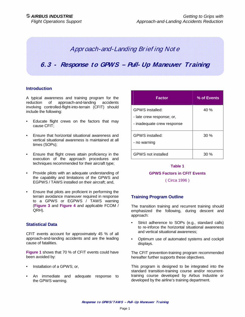
AIRBUS INDUSTRIE Getting to Grips with Flight Operations Support Approach-and-Landing Accidents Reduction
Response to GPWS/TAWS – Pull-Up Maneuver Training
Page 1
Approach-and-Landing Briefing Note
6.3 - Response to GPWS – Pull-Up Maneuver Training
Introduction A typical awareness and training program for the reduction of approach-and-landing accidents involving controlled-flight-into-terrain (CFIT) should include the following:
• Educate flight crews on the factors that may cause CFIT;
• Ensure that horizontal situational awareness and vertical situational awareness is maintained at all times (SOPs);
• Ensure that flight crews attain proficiency in the execution of the approach procedures and techniques recommended for their aircraft type;
• Provide pilots with an adequate understanding of the capability and limitations of the GPWS and EGPWS / TAWS installed on their aircraft; and,
• Ensure that pilots are proficient in performing the terrain avoidance maneuver required in response to a GPWS or EGPWS / TAWS warning (Figure 3 and Figure 4 and applicable FCOM / QRH).
Statistical Data CFIT events account for approximately 45 % of all approach-and-landing accidents and are the leading cause of fatalities. Figure 1 shows that 70 % of CFIT events could have been avoided by:
• Installation of a GPWS; or,
• An immediate and adequate response to the GPWS warning.
Factor % of Events
GPWS installed:
- late crew response; or,
- inadequate crew response
40 %
GPWS installed:
- no warning
30 %
GPWS not installed 30 %
Table 1
GPWS Factors in CFIT Events
( Circa 1996 )
Training Program Outline The transition training and recurrent training should emphasized the following, during descent and approach:
• Strict adherence to SOPs (e.g., standard calls) to re-inforce the horizontal situational awareness and vertical situational awareness;
• Optimum use of automated systems and cockpit displays.
The CFIT prevention-training program recommended hereafter further supports these objectives. This program is designed to be integrated into the standard transition-training course and/or recurrent-training course developed by Airbus Industrie or developed by the airline’s training department.

AIRBUS INDUSTRIE Getting to Grips with Flight Operations Support Approach-and-Landing Accidents Reduction
Response to GPWS/TAWS – Pull-Up Maneuver Training
Page 2
The recommended program consists of:
• A classroom briefing or a self-briefing session based on the contents of:
− the Airbus Industrie CFIT Education and Training Aid;
− the relevant Approach-and-Landing Briefing Notes and presentations;
− the description and operations of the applicable model of GPWS and EGPWS / TAWS ( FCOM and QRH ).
• The Airbus Industrie CFIT video program, illustrating the terrain escape maneuver techniques applicable to conventional aircraft and protected aircraft, respectively.
• Exercises to be incorporated in simulator training sessions during transition training and/or recurrent training.
Three typical exercises are described hereafter.
• Additional briefing material to point out the risk of CFIT during step-down non-precision approaches and the advantages of using a constant-angle stabilized profile.
Briefing Note 7.2 – Flying Constant-Angle Non-Precision Approach provides expanded information on the benefits associated with constant-angle non-precision approaches.
Simulator Requirements for CFIT Prevention Training
• Terrain should be included in the database in the vicinity of the airports selected for training.
The terrain database should extend over an area of 25-30 NM radius centered on the airfield reference point.
This simulator visual system should be able to display the terrain features.
• The capability should be provided to insert an "electronic mountain" from the instructor panel at a selected point ahead of the aircraft's present position, on its projected flight path.
Nevertheless, inserting an electronic mountain at an airport that does not feature such terrain may result in the trainee dismissing the (E)GPWS / TAWS warning (assuming a spurious warning), thus resulting in negative training.
The slope and height of the mountain should be tailored to the particular aircraft performance capability at a representative weight (e.g. maximum landing weight), so that maximum performance is required to avoid impact.
The slope of the mountain should therefore be adjustable up to at least 17 °, depending on the climb gradients that can be achieved in the escape maneuver.
• To prevent negative training, the simulator must realistically represent handling qualities and performance as the speed reduces to stick-shaker speed (or minimum speed, as applicable).
Simulator Exercises
All (E)GPWS / TAWS modes should be demonstrated.
The objective should be to gain an understanding of the parameters and limitations of the (E)GPWS / TAWS installed on the aircraft type.
These exercises can be performed in either a fixed-base simulator (FBS) or a full-flight simulator (FFS).
The following scenarios, to be performed in the FFS, are designed to introduce CFIT awareness and to demonstrate and practice the correct response to (E)GPWS / TAWS warnings.
These scenarios may be modified in accordance with the individual airline's training requirements or operating environment.

AIRBUS INDUSTRIE Getting to Grips with Flight Operations Support Approach-and-Landing Accidents Reduction
Response to GPWS/TAWS – Pull-Up Maneuver Training
Page 3
Avoidance Maneuver in VMC Objectives: Demonstrate:
• (E)GPWS / TAWS warnings and that response must be immediate;
• Pilot pull-up technique (with special reference to pitch force, as applicable, and pitch attitude); and,
• Crew coordination aspects.
Briefing: Explain the objectives, point out that this is a training exercise that is not intended to be a realistic operational situation; describe the pull-up technique required for the particular aircraft type ( Figure 3 or Figure 4 and applicable FCOM and QRH ).
Initial conditions: Establish initial approach configuration and speed, at or near the maximum landing weight, in a shallow descent or in level flight.
Procedure:
Insert an "electronic mountain" ahead of the aircraft, talk to flight crew throughout the maneuver insisting on an immediate and aggressive response. Ensure proper crew coordination, with PNF calling radio altitudes and trend (e.g. "300 ft decreasing"). Continue maneuver at maximum performance until mountain is cleared ( Figure 2 ). The duration of the maneuver should be long enough for the pilot to demonstrate proficiency at maintaining the maximum climb performance. Repeat the exercise, as needed, until crew proficiency is achieved.
Debriefing: Review the exercise, as appropriate.
(E)GPWS / TAWS Warning in IMC Objectives: To re-inforce and confirm correct response to (E)GPWS / TAWS in IMC, including pilot technique and crew coordination.
Briefing: Although the trainees will know in advance that the exercise is to be performed, explain that it is intended to simulate an inadvertent descent below MSA due to loss of situational awareness (e.g., because of a lateral navigation error, an incorrect altitude selection, an incorrect non-precision approach procedure or any other factors).
Initial conditions: Establish either one of the two following scenarios:
• Initial approach configuration and speed, at or near the maximum landing weight, in a shallow descent or in level flight (as in the first scenario).
or
• Landing configuration, V APP, at or near the maximum landing weight, on a typical 3-degree glide path.
Procedure: Insert an "electronic mountain" ahead of the aircraft; talk to flight crew throughout the maneuver insisting on an immediate and aggressive response. Ensure proper crew coordination, with PNF calling radio altitudes and trend (e.g. "300 ft decreasing..."). Continue maneuver at maximum performance until terrain is cleared ( Figure 2 ); the maneuver should be long enough for the pilot to demonstrate proficiency at maintaining the maximum climb performance. Repeat the exercise, as needed, up to proficiency.
Debriefing: Review the exercise, as appropriate.
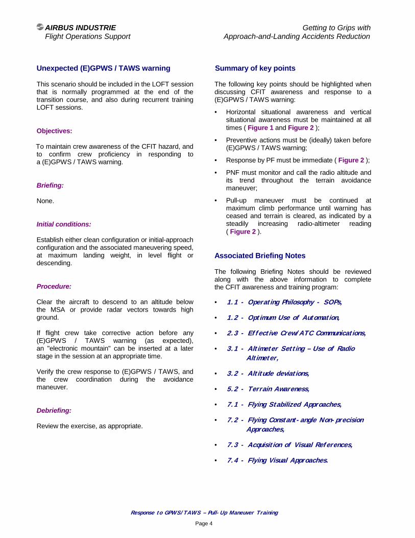
AIRBUS INDUSTRIE Getting to Grips with Flight Operations Support Approach-and-Landing Accidents Reduction
Response to GPWS/TAWS – Pull-Up Maneuver Training
Page 4
Unexpected (E)GPWS / TAWS warning This scenario should be included in the LOFT session that is normally programmed at the end of the transition course, and also during recurrent training LOFT sessions. Objectives: To maintain crew awareness of the CFIT hazard, and to confirm crew proficiency in responding to a (E)GPWS / TAWS warning. Briefing: None. Initial conditions: Establish either clean configuration or initial-approach configuration and the associated maneuvering speed, at maximum landing weight, in level flight or descending. Procedure: Clear the aircraft to descend to an altitude below the MSA or provide radar vectors towards high ground. If flight crew take corrective action before any (E)GPWS / TAWS warning (as expected), an "electronic mountain" can be inserted at a later stage in the session at an appropriate time. Verify the crew response to (E)GPWS / TAWS, and the crew coordination during the avoidance maneuver. Debriefing: Review the exercise, as appropriate.
Summary of key points The following key points should be highlighted when discussing CFIT awareness and response to a (E)GPWS / TAWS warning:
• Horizontal situational awareness and vertical situational awareness must be maintained at all times ( Figure 1 and Figure 2 );
• Preventive actions must be (ideally) taken before (E)GPWS / TAWS warning;
• Response by PF must be immediate ( Figure 2 );
• PNF must monitor and call the radio altitude and its trend throughout the terrain avoidance maneuver;
• Pull-up maneuver must be continued at maximum climb performance until warning has ceased and terrain is cleared, as indicated by a steadily increasing radio-altimeter reading ( Figure 2 ).
Associated Briefing Notes The following Briefing Notes should be reviewed along with the above information to complete the CFIT awareness and training program:
• 1.1 - Operating Philosophy - SOPs,
• 1.2 - Optimum Use of Automation,
• 2.3 - Effective Crew/ATC Communications,
• 3.1 - Altimeter Setting – Use of Radio Altimeter,
• 3.2 - Altitude deviations,
• 5.2 - Terrain Awareness,
• 7.1 - Flying Stabilized Approaches,
• 7.2 - Flying Constant-angle Non-precision Approaches,
• 7.3 - Acquisition of Visual References,
• 7.4 - Flying Visual Approaches.
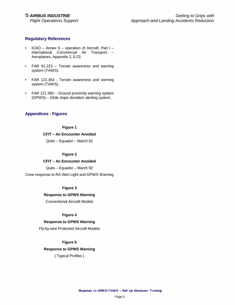
AIRBUS INDUSTRIE Getting to Grips with Flight Operations Support Approach-and-Landing Accidents Reduction
Response to GPWS/TAWS – Pull-Up Maneuver Training
Page 5
Regulatory References • ICAO – Annex 6 – operation of Aircraft, Part I –
International Commercial Air Transport – Aeroplanes, Appendix 2, 5.23.
• FAR 91.223 – Terrain awareness and warning system (TAWS).
• FAR 121.354 - Terrain awareness and warning system (TAWS).
• FAR 121.360 – Ground proximity warning system
(GPWS) – Glide slope deviation alerting system.
Appendices - Figures
Figure 1
CFIT – An Encounter Avoided
Quito – Equador – March 92
Figure 2
CFIT – An Encounter Avoided
Quito – Equador – March 92
Crew response to RA Alert Light and GPWS Warning
Figure 3
Response to GPWS Warning
Conventional Aircraft Models
Figure 4
Response to GPWS Warning
Fly-by-wire Protected Aircraft Models
Figure 5
Response to GPWS Warning
( Typical Profiles )

AIRBUS INDUSTRIE Getting to Grips with Flight Operations Support Approach-and-Landing Accidents Reduction
Response to GPWS/TAWS – Pull-Up Maneuver Training
Page 6
Figure 1
CFIT – An Encounter Avoided
Quito – Equador – March 92
Drawing adapted from “ Flight Into Terrain And the Ground Proximity Warning System “ by Don Bateman
✳ 15,460 ft
QIT 115.3 VOR-DME
✳ 13,780 ft
✳ 16,408 ft
D 16.0 QMS
D 16.0 QIT
QMS 115.0 VOR-DME
Pull-up initiated Projected impact 13,200 ft
Climbing to 17,000 ft
QUITO, ECUADOR MARISCAL SUCRE INTL
VOR ILS RWY 35 LOC 110.5 IQO
• ILS approach RWY 35 - Night time - IMC - Rain
• QMS VOR-DME ( 115.0 ) tuned instead of QIT ( 115.3 )
• Procedure turn flown with reference to QMS, hence 12 NM further south
• Crew alerted by 2500-ft radio-altimeter light
• Crew responded to GPWS MK II warning: Terrain - Terrain - Pull up ! Pull up !
• GPWS warning remained activated during 40 seconds
• High terrain was avoided by only 150 ft RA

AIRBUS INDUSTRIE Getting to Grips with Flight Operations Support Approach-and-Landing Accidents Reduction
Response to GPWS/TAWS – Pull-Up Maneuver Training
Page 7
Figure 2
CFIT – An Encounter Avoided
Quito – Equador – March 92
Crew response to RA Alert Light and GPWS Warning
Drawing adapted from “ Flight Into Terrain And the Ground Proximity Warning System “ by Don Bateman
14 15 16 17 18 19 20 21 22 23 24 25 26
Distance from RWY 35 - NM
10 000
11 000
12 000
13 000
14 000
15 000
16 000
17 000
Altitude ( ft MSL ) Terrain along track
Terrain if full procedure turn to right
Flight path
MK II GPWS warning Terrain-Terrain Pull up ! Pull up !
16 DME QMS ( 28 DME QIT )
150 Radial QMS ( outbound ) 2500 ft RA
Light 2500 ft RA
Light 150 ft RA
17 degree pitch Maximum thrust
200 kt 4000 ft/mn
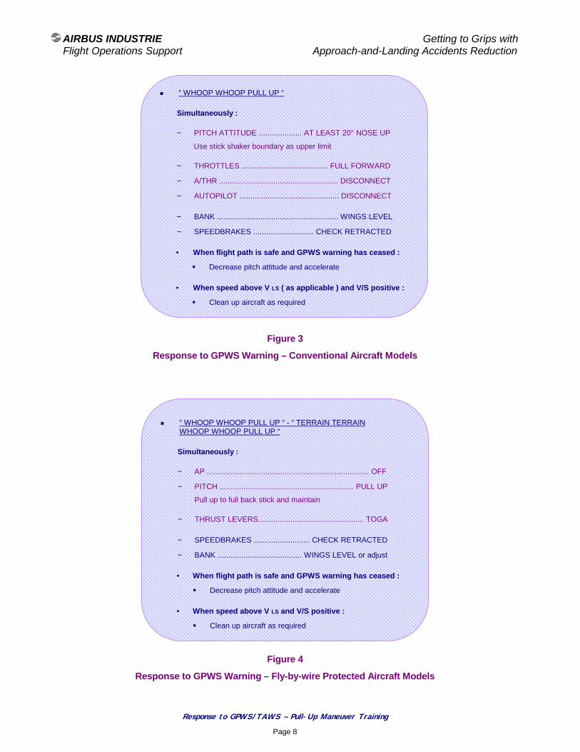
AIRBUS INDUSTRIE Getting to Grips with Flight Operations Support Approach-and-Landing Accidents Reduction
Response to GPWS/TAWS – Pull-Up Maneuver Training
Page 8
Figure 3
Response to GPWS Warning – Conventional Aircraft Models
Figure 4
Response to GPWS Warning – Fly-by-wire Protected Aircraft Models
! “ WHOOP WHOOP PULL UP “
Simultaneously :
− PITCH ATTITUDE .................... AT LEAST 20° NOSE UP
Use stick shaker boundary as upper limit
− THROTTLES ........................................ FULL FORWARD
− A/THR ....................................................... DISCONNECT
− AUTOPILOT .............................................. DISCONNECT
− BANK ........................................................ WINGS LEVEL
− SPEEDBRAKES ............................ CHECK RETRACTED
• When flight path is safe and GPWS warning has ceased :
# Decrease pitch attitude and accelerate
• When speed above V LS ( as applicable ) and V/S positive :
# Clean up aircraft as required
! “ WHOOP WHOOP PULL UP “ - “ TERRAIN TERRAIN WHOOP WHOOP PULL UP “
Simultaneously :
− AP ........................................................................... OFF
− PITCH .............................................................. PULL UP
Pull up to full back stick and maintain
− THRUST LEVERS................................................. TOGA
− SPEEDBRAKES .......................... CHECK RETRACTED
− BANK ....................................... WINGS LEVEL or adjust
• When flight path is safe and GPWS warning has ceased :
# Decrease pitch attitude and accelerate
• When speed above V LS and V/S positive :
# Clean up aircraft as required
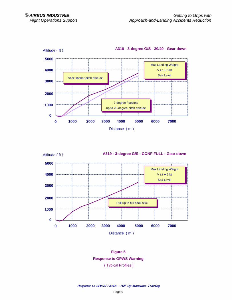
AIRBUS INDUSTRIE Getting to Grips with Flight Operations Support Approach-and-Landing Accidents Reduction
Response to GPWS/TAWS – Pull-Up Maneuver Training
Page 9
Figure 5
Response to GPWS Warning
( Typical Profiles )
Altitude ( ft )
Distance ( m )
1000
2000
3000
4000
5000
0 1000 2000 3000 4000 5000 6000 7000
0
A319 - 3-degree G/S - CONF FULL - Gear down
Max Landing Weight
V LS + 5 kt
Sea Level
Pull up to full back stick
Altitude ( ft )
Distance ( m )
1000
2000
3000
4000
5000
0 1000 2000 3000 4000 5000 6000 7000
0
A310 - 3-degree G/S - 30/40 - Gear down
Max Landing Weight
V LS + 5 kt
Sea Level Stick shaker pitch attitude
3-degree / second
up to 20-degree pitch attitude
AIRBUS INDUSTRIE Getting to Grips with Flight Operations Support Approach-and-Landing Accidents Reduction
Bounce Recovery – Rejected Landing
Page 1
Approach-and-Landing Briefing Note
6.4 - Bounce Recovery – Rejected Landing
Introduction A rejected landing (also referred to as an aborted landing) is defined as a go-around maneuver initiated after touchdown of the main landing gear or after bouncing. Although a rare occurrence, a rejected landing is a challenging maneuver decided and conducted in an unanticipated and unprepared manner. The objective of this Briefing Note is to define:
• Applicable decision criteria for:
− Full-stop landing; or,
− Rejected landing and go-around; and,
• Procedures and techniques for bounce recovery, including:
− Continued landing; or,
− Rejected landing (i.e., go-around). Statistical data No global statistical data are available on rejected landing incidents or accidents but the following three events illustrate the circumstances that may lead a flight crew to reject the landing, and the possible consequences of such a maneuver:
• Tail strike following a go-around initiated due to directional control difficulties after thrus t reverser selection;
• Climb performance limitation following the undue selection of reverse thrust during a touch-and-go and failure of one reverser to stow; and,
• Loss of control following a go-around initiated after thrust reverser selection (because of a vehicle obstructing the runway) and failure of one reverser to stow.
Touch-and-go ( training only ) Although a touch-an-go is essentially a training exercise, the conditions required for the safe conduct of this maneuver provide a valuable introduction to the discussion of rejected landings. Preconditions: Four preconditions (usually referred to as the “4-No rule”) must be observed prior to initiating a touch-and-go:
• No ground spoilers:
− ground spoilers must not be armed or manually selected after touchdown;
• No autobrake:
− autobrake must not be armed;
• No reverse:
− thrust reversers must not be selected upon touchdown; and,
• No pedal braking:
− pedal braking must not be used after touchdown.
Performing a rejected landing in revenue service (i.e., with ground spoilers and autobrake armed, being ready to select reverse thrust upon touchdown) creates an added challenge.

AIRBUS INDUSTRIE Getting to Grips with Flight Operations Support Approach-and-Landing Accidents Reduction
Bounce Recovery – Rejected Landing
Page 2
Aircraft reconfiguration: After touchdown for a planned touch-and-go, the aircraft must be reconfigured to a takeoff configuration:
• Flaps reset to a takeoff configuration;
• Pitch trim reset within the takeoff trim setting range;
• Rudder trim reset (as applicable); and,
• Throttle/thrust levers standup, as required (for symmetrical engine acceleration).
Task sharing: Performing a planned touch-and-go is a dynamic and demanding maneuver in terms of task sharing:
• The PF (trainee) is responsible for:
− Tracking the runway centerline;
− Advancing the throttle levers slightly above idle.
• The PNF (instructor) is responsible for:
− Reconfiguring the aircraft for takeoff;
− Resetting systems, as required;
− Monitoring engine parameters and flight modes annunciations;
− Performing the takeoff callouts;
− Deciding to abort the takeoff, if required; and,
− Ensuring back-up of PF during rotation and initial climb.
Performing a rejected landing (i.e., a non-anticipated and non-prepared event) further amplifies the importance for the PF and PNF to strictly adhere to the defined task sharing and to concentrate on their respective tasks.
Bouncing and bounce recovery Bouncing at landing usually is the result of one or a combination of the following factors:
• Loss of visual references;
• Excessive sink rate;
• Late flare initiation;
• Incorrect flare technique;
• Excessive airspeed; and/or,
• Power-on touchdown (preventing the automatic extension of ground spoilers, as applicable).
The bounce recovery technique depends on the height reached during the bounce. Recovery from a light bounce (5 ft or less): In case of a light bounced, the following typical recovery technique can be applied:
• Maintain or regain a normal landing pitch attitude (do not increase pitch attitude as this could cause a tailstrike);
• Continue the landing;
• Use power as required to soften the second touchdown; and,
• Be aware of the increased landing distance. Recovery from a high bounce (more than 5 ft): In case of a more severe bounce, do not attempt to land, as the remaining runway length might not be sufficient to stop the aircraft. The following generic go-around technique can be applied:
• Maintain or regain a normal landing pitch attitude;
• Initiate a go-around by triggering go-around levers/switches and advancing throttle levers to the go-around thrust position;

AIRBUS INDUSTRIE Getting to Grips with Flight Operations Support Approach-and-Landing Accidents Reduction
Bounce Recovery – Rejected Landing
Page 3
• Maintain the landing flaps configuration or set the required flaps configuration, as set forth in the applicable FCOM;
• Be ready for a possible second touchdown;
• Be alert to apply forward force on control column (side stick) and reset the pitch trim nose down as engines spool up (conventional aircraft models only);
• When safely established in the go-around and no risk of further touchdown exists (i.e., with a steady positive rate of climb), follow normal go-around procedures; and,
• Reengage automation, as desired, to reduce workload.
Commitment for Full-Stop Landing Landing incidents and accidents clearly demonstrate that after the thrust reversers have been deployed (even at reverse idle), the landing must be completed to a full stop, as a successful go-around may not be possible. The following occurrences have resulted in a significantly reduced rate of climb or in departure from controlled flight:
• Thrust asymmetry resulting from asymmetrical engine spool up (i.e., asymmetrical engine acceleration characteristics from a ground idle level);
• Thrust asymmetry resulting from one thrust reverser going to the stow position faster than the other one; and,
• Severe thrust asymmetry resulting from one thrust reverser failing to re-stow.
Commitment for Go-around If a rejected landing is initiated, the flight crew must be committed to proceed with the go-around maneuver and not retard the throttle levers in an ultimate decision to complete the landing. Reversing a go-around decision usually is observed when the decision to reject the landing and to initiate a go-around is taken by the first officer (as PF) but is overridden by the captain. Runway overruns, impact with obstructions and major aircraft damage (or post impact fire) often are the consequences of reversing an already initiated rejected landing. Summary of Key Points The SOPs should define the respective decision criteria for:
• Full-stop landing; or,
• Rejected landing and go-around.
Procedures and techniques should be published for bounce recovery, including:
• Continued landing; or,
• Rejected landing (i.e., go-around). Associated Briefing Notes The following Briefing Notes can be reviewed in association with the above information:
• 6.1 - Being Prepared to Go-around,
• 7.1 - Flying Stabilized Approaches,
• 8.1 - Preventing Runway Excursions and Overruns.

AIRBUS INDUSTRIE Getting to Grips with Flight Operations Support Approach-and-Landing Accidents Reduction
Chapter 7
Approach Techniques

AIRBUS INDUSTRIE Getting to Grips with Flight Operations Support Approach-and-Landing Accidents Reduction
Flying Stabilized Approaches
Page 1
Approach-and-Landing Briefing Note
7.1 - Flying Stabilized Approaches
Introduction Rushed and unstabilized approaches are the largest contributory factor in CFIT and other approach-and-landing accidents. Rushed approaches result in insufficient time for the flight crew to correctly:
• Plan;
• Prepare; and,
• Execute a safe approach.
This Briefing Note provides an overview and discussion of:
• Criteria defining a stabilized approach; and,
• Factors involved in rushed and unstabilized approaches.
Note :
Flying stabilized approaches complying with the stabilization criteria and approach gates defined hereafter, does not preclude flying a Delayed Flaps Approach (also called a Decelerated Approach) as dictated by ATC requirements. Statistical Data Continuing an unstabilized approach is a causal factor in 40 % of all approach-and-landing accidents. Table 1 and Table 2 show the factors involved in rushed and unstabilized approaches and the consequences of continuing an unstabilized approach.
Factor % of Events
High and/or fast approach
or
Low and/or slow approach
66 %
Flight-handling difficulties :
- demanding ATC clearances
- adverse wind conditions
45 %
Table 1
Factors Involved
Factor % of Events
Off-runway touchdown,
Tail strike,
Runway excursion or overrun
75 %
CFIT -- %
Loss of control -- %
Table 2
Consequences of Continued Approach

AIRBUS INDUSTRIE Getting to Grips with Flight Operations Support Approach-and-Landing Accidents Reduction
Flying Stabilized Approaches
Page 2
Approach Gates – Stabilization Heights The following approach gates and minimum stabilization heights are recommended to achieve timely stabilized approaches:
Meteorological Conditions
Height above Airfield Elevation
IMC 1000 ft
VMC 500 ft
Table 3
Minimum Stabilization Heights
Defining a Stabilized Approach An approach is considered stabilized only if all the following conditions are achieved before or when reaching the applicable stabilization height: For all types of approach:
The aircraft is on the correct lateral and vertical flight
path
(based on navaids guidance or visual references)
Only small changes in heading and pitch are required to maintain this flight path
The aircraft is in the desired landing configuration
The power is stabilized and the aircraft is trimmed to maintain the target final approach speed
on the desired glide path
The landing checklist has been accomplished as well as any required specific briefing
No flight parameter exceeds the criteria provided in Table 6 and Table 7
Table 6 and Table 7 also define the criteria for flight-parameters excessive-deviation callouts
Table 4
Note :
Non-normal conditions requiring deviation from the above elements of a stabilized approach should be briefed formally.

AIRBUS INDUSTRIE Getting to Grips with Flight Operations Support Approach-and-Landing Accidents Reduction
Flying Stabilized Approaches
Page 3
For visual and circling approaches:
For visual approaches, wings must be level on final
when the aircraft reaches 500 ft above airfield elevat ion
For circling approaches, wings must be level on final when the aircraft reaches
300 ft above airfield elevation
Table 5
Excessive flight parameter deviation callouts criteria When reaching the applicable stabilization height and below, a callout should be performed by the PNF if any flight parameter exceeds the limits provided in Table 6 and Table 7.
( * ) :
The final approach speed V APP is considered to be equal to V REF + 5 kt (or V LS + 5 kt, as applicable).
V REF is the reference target threshold speed in the full flaps landing configuration (i.e., in the absence of airspeed corrections because of wind, windshear or non-normal configuration).
( ** ) :
Refer to the applicable SOPs for applicable pitch attitude limits.
( *** ) :
Monitoring the ground speed provides an awareness of a possible impending wind shear.
Maintaining the ground speed above V APP – 10 kt provides an energy margin, in readiness for the sudden head wind to tail wind shift usually associated with wind shear.
Maintaining a minimum ground speed is performed automatically when flying in managed-speed on fly-by-wire aircraft models.
For all types of constant-angle approaches:
Parameter Callout Criteria
Airspeed Lower than V APP – 5 kt
or
Greater than V APP + 10 kt
( * )
Vertical Speed
Greater than – 1000 ft/mn
Note :
If the approach requires more than – 1000 ft/mn
vertical speed (e.g., for GS capture from above), PF and PNF should discuss the
required vertical speed
Pitch Attitude
Lower than ( ** ) Nose Down
or
Greater than ( ** ) Nose Up
Bank Angle
Greater than 7 degrees
Ground Speed
Lower than V APP - 10 kt
( *** )
Table 6
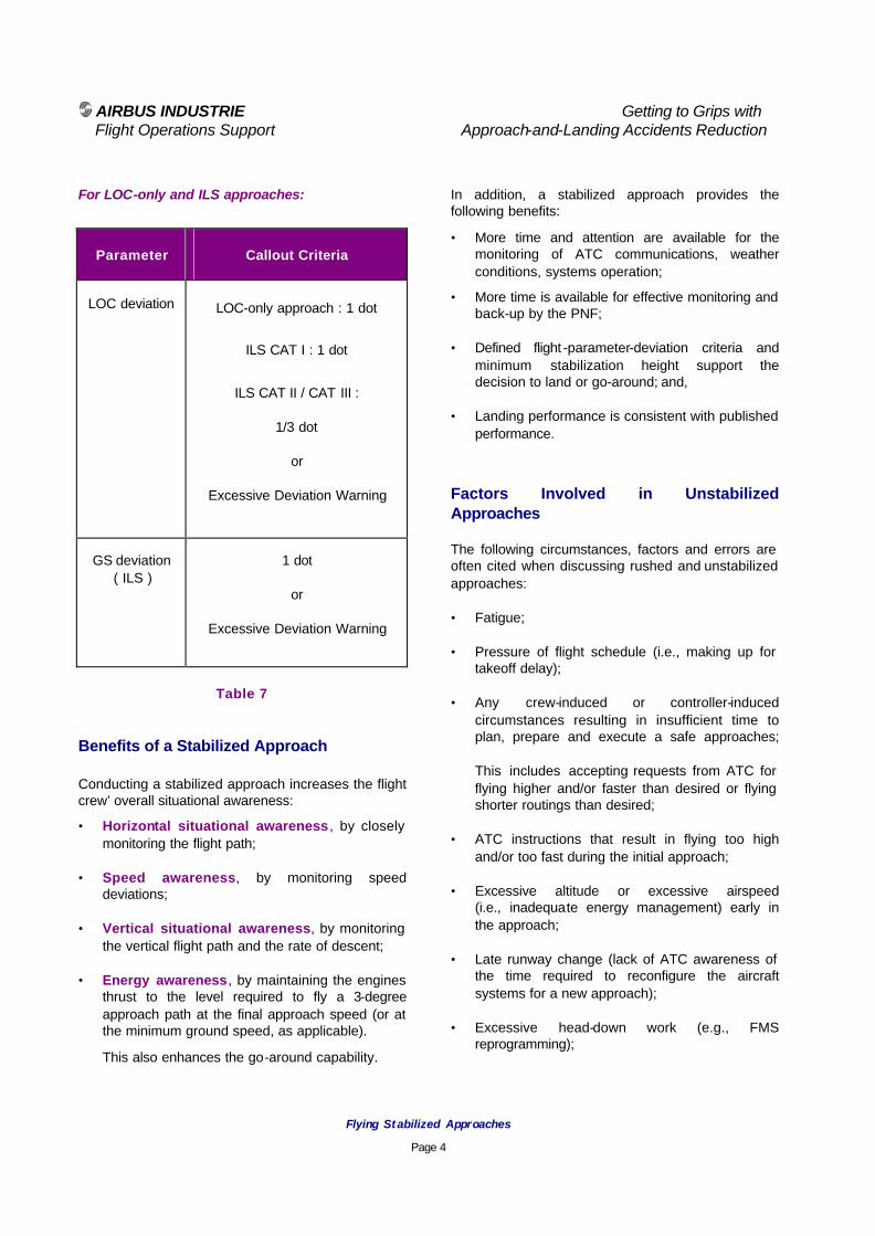
AIRBUS INDUSTRIE Getting to Grips with Flight Operations Support Approach-and-Landing Accidents Reduction
Flying Stabilized Approaches
Page 4
For LOC-only and ILS approaches:
Parameter Callout Criteria
LOC deviation LOC-only approach : 1 dot
ILS CAT I : 1 dot
ILS CAT II / CAT III :
1/3 dot
or
Excessive Deviation Warning
GS deviation ( ILS )
1 dot
or
Excessive Deviation Warning
Table 7 Benefits of a Stabilized Approach Conducting a stabilized approach increases the flight crew’ overall situational awareness:
• Horizontal situational awareness , by closely monitoring the flight path;
• Speed awareness, by monitoring speed deviations;
• Vertical situational awareness, by monitoring the vertical flight path and the rate of descent;
• Energy awareness, by maintaining the engines thrust to the level required to fly a 3-degree approach path at the final approach speed (or at the minimum ground speed, as applicable).
This also enhances the go-around capability.
In addition, a stabilized approach provides the following benefits:
• More time and attention are available for the monitoring of ATC communications, weather conditions, systems operation;
• More time is available for effective monitoring and back-up by the PNF;
• Defined flight -parameter-deviation criteria and minimum stabilization height support the decision to land or go-around; and,
• Landing performance is consistent with published performance.
Factors Involved in Unstabilized Approaches The following circumstances, factors and errors are often cited when discussing rushed and unstabilized approaches:
• Fatigue;
• Pressure of flight schedule (i.e., making up for takeoff delay);
• Any crew-induced or controller-induced circumstances resulting in insufficient time to plan, prepare and execute a safe approaches; This includes accepting requests from ATC for flying higher and/or faster than desired or flying shorter routings than desired;
• ATC instructions that result in flying too high and/or too fast during the initial approach;
• Excessive altitude or excessive airspeed (i.e., inadequate energy management) early in the approach;
• Late runway change (lack of ATC awareness of the time required to reconfigure the aircraft systems for a new approach);
• Excessive head-down work (e.g., FMS reprogramming);

AIRBUS INDUSTRIE Getting to Grips with Flight Operations Support Approach-and-Landing Accidents Reduction
Flying Stabilized Approaches
Page 5
• Short outbound leg or short down-wind leg (e.g., in case of unidentified traffic in the area);
• Late takeover from automation (e.g., in case of AP failing to capture the GS, usually due to crew failure to arm the approach mode);
• Premature or late descent due to absence of positive FAF identification;
• Insufficient awareness of wind conditions:
− tailwind component;
− low altitude wind shear;
− local wind gradient and turbulence (e.g., caused by terrain or buildings); or,
− recent weather along the final approach path (e.g., downdraft caused by a descending cold air mass following a rain shower);
• Incorrect anticipation of aircraft deceleration characteristics in level flight or on a 3-degree glideslope;
• Failure to recognize deviations or to remember the excessive-parameter-deviation criteria;
• Belief that the aircraft will be stabilized at the stabilization height or shortly thereafter;
• Excessive confidence by the PNF that the PF will achieve a timely stabilization;
• PF/PNF over reliance on each other to call excessive deviations or to call for a go-around; and,
• Visual illusions during the visual segment. Deviations Observed in Unstabilized Approaches The following procedure deviations or flight path excursions often are observed, alone or in combination, in rushed and unstabilized approaches (figures provided between brackets reflect extreme deviations observed in actual unstabilized approaches, worldwide).
• Full approach flown at idle down to touchdown, because of excessive airspeed and/or altitude early in the approach;
• Steep approach (i.e., above desired flight path with excessive vertical speed up to – 2200 ft/mn, flight path angle up to 15 % gradient / 9-degree slope);
Steep approaches appear to be twice as frequent as shallow approaches;
• Shallow approach (i.e., below desired glide path);
• Low airspeed maneuvering (i.e., inadequate energy management);
• Excessive bank angle when capturing the final approach course (up to 40-degree);
• Activation of a GPWS warning:
- Mode 1 : SINK RATE;
- Mode 2A : TERRAIN (not full flaps);
- Mode 2B : TERRAIN (full flaps).
• Late extension of flaps or flaps load relief system activation (as applicable), resulting in the late effective extension of flaps;
• Flight-parameter excessive deviation when crossing the stabilization height:
- Excessive airspeed (up to V REF + 70 kt);
- Not aligned (up to 20-degree heading difference);
- Excessive bank angle (up to 40 -degrees);
- Excessive vertical speed (up to – 2000 ft/mn);
- Excessive glide slope deviation (up to 2 dots);
• Excessive bank angle, excessive sink rate or excessive maneuvering while performing a side-step;

AIRBUS INDUSTRIE Getting to Grips with Flight Operations Support Approach-and-Landing Accidents Reduction
Flying Stabilized Approaches
Page 6
• Speedbrakes being still extended when in short final (i.e., below 1000 ft above airfield elevation);
• Excessive flight-parameter deviation(s) down to runway threshold;
• High runway-threshold crossing (up to 220 ft);
• Long flare and extended touchdown. Company’s Prevention Strategies and Personal Lines-of-defense Company’s prevention strategies and personal lines-of-defense to reduce the number of unstabilized approaches should:
• Identify and minimize the factors involved;
• Provide recommendations for the early detection and correction of unstabilized approaches.
The following four-step strategy is proposed:
• Anticipate;
• Detect;
• Correct; and,
• Decide.
Anticipate: Some factors likely to result in a rushed and unstabilized approach can be anticipated. Whenever practical, flight crews and controllers should avoid situations that may result in rushed approaches. The descent-and-approach briefing provides an opportunity to identify and discuss factors such as :
• Non-standard altitude or speed restrictions requiring a careful energy management :
An agreed strategy should be defined for the management of the descent, deceleration and stabilisation (i.e., following the concepts of next targets and approach gate);
This strategy will constitute a common objective and reference for the PF and PNF.
Detect: Defined excessive-parameter-deviation criteria and a defined stabilization height provide the PF and PNF with a common reference for effective:
• Monitoring (i.e., early detection of deviations); and,
• Back-up (i.e., timely and precise deviation callouts for effective corrections).
To provide the time availability and attention required for an effective monitoring and back-up, the following should be avoided:
• Late briefings;
• Unnecessary radio calls (e.g., company calls);
• Unnecessary actions (e.g., use of ACARS); and,
• Non-pertinent intra-cockpit conversations (i.e., breaking the sterile-cockpit rule).
Reducing the workload and cockpit distractions and/or interruptions also provides the flight crew with more alertness and availability to:
• Cope with fatigue;
• Comply with an unanticipated ATC request (e.g., runway change or visual approach);
• Adapt to changing weather conditions or approach hazards; and,
• Manage a system malfunction (e.g., flaps jamming or gear failing to extend or downlock).
Correct: Positive corrective actions should be taken before deviations develop into a challenging or a hazardous situation in which the only safe action is a go-around. Corrective actions may include:
• The timely use of speed brakes or the early extension of landing gear to correct an excessive altitude or an excessive airspeed;
• Extending the outbound leg or downwind leg.

AIRBUS INDUSTRIE Getting to Grips with Flight Operations Support Approach-and-Landing Accidents Reduction
Flying Stabilized Approaches
Page 7
Decide: An immediate go-around must be performed if:
• The approach is not stabilized when reaching the minimum stabilization height; or,
• Any flight parameter exceeds the related excessive-deviation criteria (other than transiently) when below the minimum stabilization height.
The following behaviors often are involved in the continuation of an unstabilized approach:
• Confidence in a quick recovery (i.e., postponing the go-around decision when parameters are converging toward target values);
• Overconfidence because of a long and dry runway and/or a low gross-weight, although airspeed and/or vertical speed are excessive;
• Inadequate readiness or lack of commitment to conduct a go-around;
A change of mindset should take place from:
− “We will land unless …”; to,
− “Let’s be prepared for a go-around and we will land if the approach is stabilized and if we have sufficient visual references to make a safe approach and landing”.
• Go-around envisaged but not initiated because the approach was considered being compatible with a safe landing; and,
• Absence of decision due to fatigue or workload (i.e., failure to remember the applicable excessive deviation criteria).
Next Target and Approach Gate Throughout the entire flight a next target should be defined to stay ahead of the aircraft at all times. The defined next target should be any required combination of:
• A position;
• An altitude;
• A configuration;
• A speed;
• A vertical speed or flight path angle; and,
• A power setting.
During the approach and landing, the successive next targets should be achieved for the approach to be continued. If the crew anticipates that one of the elements of the next target will not be achieved, the required corrective action(s) should be taken without delay. The minimum stabilization height constitutes a particular gate along the final approach; a go-around must be initiated if:
• The required configuration and speed is not obtained or the flight path is not stabilized when reaching the stabilization height;
or,
• The aircraft becomes unstabilized below the stabilization height.

AIRBUS INDUSTRIE Getting to Grips with Flight Operations Support Approach-and-Landing Accidents Reduction
Flying Stabilized Approaches
Page 8
Summary of Key Points Three essential parameters need to be stabilized for a safe approach:
• Aircraft track;
• Flight path angle; and,
• Airspeed.
Depending on the type of approach and aircraft equipment, the most appropriate level of automation and visual cues should be used to achieve and monitor the stabilization of the aircraft. When breaking-out of the cloud overcast and transitioning to visual references, the pilot’s perception of the runway and outside environment should be kept constant by maintaining the:
• Drift correction, to continue tracking the runway centerline, resisting the tendency to prematurely align the aircraft with the runway centerline;
• Aiming point (i.e., the touchdown zone), to remain on the correct flight path until flare height, resisting the tendency to move the aiming point closer and, thus, descend below the desired glide path (i.e., “duck-under”); and,
• Final approach speed and ground speed, to maintain the energy level.
Associated Briefing Notes The following Briefing Notes can be reviewed in association with the above information:
• 4.1 - Descent and Approach Profile Management,
• 4.2 - Energy Management during Approach,
• 6.1 - Being Prepared to Go-around,
• 7.2 - Flying Constant-angle Non-precision Approaches,
• 8.2 - The Final Approach Speed,
• 8.3 - Factors Affecting Landing Distances.

AIRBUS INDUSTRIE Getting to Grips with Flight Operations Support Approach-and-Landing Accidents Reduction
Flying Stabilized Approaches
Page 9
Regulatory references
• ICAO – Annex 6 – Operations of Aircraft, Part I – International Commercial Air transport – Aeroplanes, Appendix 2, 5.18, 5.19.
• ICAO – Procedures for Air navigation services – Aircraft Operations (PANS -OPS, Doc 8168), Volume I – Flight Procedures (particularly, Part IX - Chapter 1 - Stabilized Approach – Parameters, Elements of a Stabilized Approach and Go-around Policy).
• ICAO – Preparation of an Operations Manual (Doc 9376).
• FAA Document 8430.6A – Air Carrier Operation Inspector Handbook – Chapter 7 – paragraph 951.d.(4).(f): procedures for altitude and vertical speed monitoring.
• FAA Document 8400.10, stating that a sink rate of greater than approximately 1000 ft/mn is unacceptable below 1000 ft above airfield elevation.
Other References • U.S. National Transportation Safety Board
(NTSB) – Report NTSB-AAS-76-5 –.Special Study: Flight Crew Coordination Procedure in Air Carrier Instrument Landing System Approach Accidents.

AIRBUS INDUSTRIE Getting to Grips with Flight Operations Support Approach-and-Landing Accidents Reduction
Flying Constant-Angle Non-Precision Approaches
Page 1
Approach-and-Landing Briefing Note
7.2 - Flying Constant-Angle Non-Precision Approaches
Introduction Planning and conducting a non-precision approach (NPA) is certainly the most challenging and demanding part of a flight, this includes:
• Decision making on strategies and options;
• Effective task-sharing;
• Crew coordination (monitoring and callouts); and,
• CFIT awareness (response to GPWS or EGPWS / TAWS warning).
Various types of NPAs (also called non-ILS approaches) share common features but also involve specific techniques, depending on the navaid being used or on the strategy being adopted for:
• Lateral and vertical guidance;
• Descending from the final approach fix (FAF) down to the minimum descent altitude(height) MDA(H); and,
• Making the decision before or when reaching the MDA(H).
This Briefing Note describes the features common to all types of non-precision approaches and the specific features of each individual type of approach. This Briefing Note highlights the technique of constant-angle (constant-slope) non-precision approach, as opposed to the traditional step-down technique.
Statistical Data Almost 60 % of CFIT incidents and accidents occur during step-down non-precision approaches. The constant-angle non-precision approach (CANPA) technique, described in this Briefing Note, should be implemented and trained worldwide for preventing CFIT and other approach-and-landing accidents. Defining Non-Precision Approaches A non-precision approach is an instrument approach that does not incorporate vertical guidance (i.e., not using a glide slope beam). The navaid being used is therefore primarily used for lateral guidance. Non-precision instrument approaches include the use of the following navaids: • NDB, VOR, LOC-only, VOR-DME, LOC-DME,
LOC BCK CRS. Note 1:
The LDA (LOC-type Directional Aid), SDF (Simplified Directional Facility) and Circling approaches share most of the features and procedures applicable to other non-precision approaches. Note 2:
GPS approaches performed in overlay to a conventional non-precision approach and RNAV/RNP approaches, with or without GPS PRIMARY, also share most of the strategies and procedures described in this Briefing Note.

AIRBUS INDUSTRIE Getting to Grips with Flight Operations Support Approach-and-Landing Accidents Reduction
Flying Constant-Angle Non-Precision Approaches
Page 2
Instrument approaches usually consist of three approach segments:
• Initial approach :
− From an initial approach fix (IAF) to the intermediate fix (IF), if defined;
− Minimum obstacle clearance: 1000 ft;
• Intermediate approach :
− From the IF to the final approach fix (FAF);
− Minimum obstacle clearance: 500ft; and,
• Final approach:
− From the FAF to the MDA(H) and visual descent/decision point (VDP) or MAP;
− Minimum obstacle clearance: 250 ft.
For non-precision approaches, the intermediate approach is a transition segment during which the aircraft is configured for the final approach:
• Landing gear extended;
• Landing flaps configuration established;
• Speed stabilized on the final approach speed;
• Aircraft aligned with the final approach course; and,
• Landing checklist and briefings completed.
Figure 1
Step-down Final Approach
Notes : The charted MDA(H) is referenced to the touchdown zone elevation (TDZE), to the runway (RWY) or the airport reference point (APT or ARP). The ICAO PANS-OPS define the MDA(H) as a function of the obstacle clearance altitude (height) [OCA(H)]:
MDA(H) = OCA(H) + 30 ft
VDP Concept The Visual Descent/Decision Point (VDP) is a point in the approach, at the MDA(H), where the aircraft is approximately on a 3-degree glide path, as illustrated by Figure 2.
Figure 2
Visual Descent Point ( VDP ) Concept The VDP location is defined by:
• Distance from a VOR-DME or LOC-DME;
or,
• Time from the FAF. The VDP should be considered as the last point from which a stabilized visual descent to the runway can be conducted.
MDA(H)
Go-Around
Decision Limit
V
FAF ( or FDF )
✠
MAP
M
MDA(H)
Decision at VDP :
- Descent from VDP
or
- Go-around
FAF ( or FDF ) VDP
✠
MAP
M V

AIRBUS INDUSTRIE Getting to Grips with Flight Operations Support Approach-and-Landing Accidents Reduction
Flying Constant-Angle Non-Precision Approaches
Page 3
Benefits of a Constant-Angle Final Approach Step-down approaches are based solely on an obstacle-clearance profile; step-down approaches are not optimized for modern commercial jetliners. Flying a constant-angle approach profile:
• Provides a more stabilized flight path;
• Reduces the workload during this critical flight phase; and,
• Eliminates the risk of error in step-down distances / altitudes and the need for a level-off at the MDA(H).
This reduces the risk of CFIT.
Figure 3
Constant-angle Final Approach
Strategies and Options Planning a non-precision or RNAV (aRea NAVigation) approach requires defining strategies and options for:
• Lateral guidance :
− use of selected modes (selected heading mode and localizer mode); or,
− use of FMS lateral navigation (NAV mode), until LOC interception or down to MDA(H).
• Vertical guidance :
− use of selected modes (altitude hold mode and V/S mode); or,
− use of FMS vertical navigation down to the FAF (or beyond, as applicable, in accordance with the FCOM).
• Final descent from FAF (or final descent fix):
− use of a step-down descent with level off at MDA(H); or,
− use of a continuous constant-angle descent with decision before or when reaching MDA(H).
Notes :
The requirement to make the decision before or when reaching the MDA(H) – i.e. the allowance to descend below the MDA(H) during the go-around maneuver (dip thru) – depends upon the applicable operational regulation.
On a constant-angle non-precision approach, the MDA(H) may be considered as a DA(H) only if the approach has been surveyed and approved by the state navigation agency and/or operational authorities.
• Use of inertial flight path vector (as available), with or without the autopilot (AP) engaged.
MDA(H)
Go-Around
Decision
V
FAF ( or FDF ) VDP
✠
MAP
M V

AIRBUS INDUSTRIE Getting to Grips with Flight Operations Support Approach-and-Landing Accidents Reduction
Flying Constant-Angle Non-Precision Approaches
Page 4
A non-precision approach may be conducted using either:
• Lateral navigation guidance, with monitoring of raw data;
or,
• Raw data only;
or,
• Raw data supported by the use of the flight path vector (as available).
A non-precision approach may be conducted with the AP engaged:
• Using FMS guidance with:
− lateral navigation until LOC interception or down to the MDA(H); and,
− vertical navigation down to the FAF (or beyond, as applicable in accordance with the FCOM), then using vertical speed mode down to the MDA(H); or,
• Using selected guidance: heading mode and altitude hold or vertical speed modes, after leaving the IAF and down to the MDA(H).
The autothrottle/autothrust system should be engaged, in the speed mode. CFIT Awareness During the final descent to the MDA(H), PF and PNF should monitor the vertical flight path and lateral flight path, and should not descend to the next step-down altitude before reaching the associated descent fix (DME distance or other reference). In IMC or at night, flight crews should respond immediately to any GPWS or EGPWS / TAWS warning. Descending Below MDA During a non-precision approach the PF is engaged in either handflying the aircraft or supervising the AP operation, the PNF is in charge of acquiring and announcing the visual references.
Continuing the approach below the MDA(H) is permitted only if at least one of the visual references is distinctly visible and identifiable by the PF (refer to Briefing Note 7.3 - Acquisition of Visual References). The landing following a non-precision approach is a visual and manual landing. Standard Operating Procedures The importance of task sharing, standard calls and altitude callouts or parameter excessive-deviation callouts must be emphasized. Refer also to the following Briefing Notes:
• 1.1 – Operating Philosophy - SOPs,
• 1.4 - Standard Calls.
The following overview outlines the actions and standard calls required by SOPs and illustrates the typical phases of the approach and the sequence of decisions involved in a non-precision approach: Descent / Approach Preparation:
• Anticipate and confirm the runway in use and the type of approach to be conducted.
• Define the approach strategy for lateral guidance:
− Use of selected heading mode and navaid raw data;
or,
− Use of FMS lateral navigation (NAV mode) with monitoring of raw data, if :
! the approach is defined in the FMS navigation database; and,
! the FMS navigation accuracy meets the criteria for approach;
(typically, better than 2 Nm in terminal area and better than 1 Nm for approach).

AIRBUS INDUSTRIE Getting to Grips with Flight Operations Support Approach-and-Landing Accidents Reduction
Flying Constant-Angle Non-Precision Approaches
Page 5
• Define the approach strategy for vertical guidance:
− Use of altitude hold and vertical speed mode;
or,
− Use of FMS vertical navigation mode, down to the FAF (or beyond, as applicable, in accordance with the FCOM);
• Insert the desired runway, type of approach and STAR (from the database) in the FMS flight plan;
• Enter the descent and surface winds on the appropriate FMS page, as applicable;
• Enter the landing configuration and wind correction on the appropriate FMS page, as applicable;
• If the use of the vertical navigation mode is authorized after the FAF, enter the MDA(H) on the appropriate FMS page;
• Set-up navaids (identify, as required); and,
• Plan the descent for reaching the IAF at the prescribed altitude and planned airspeed.
Approach Briefing: For a detailed overview of the approach briefing, refer to the Briefing Note 1.6 – Approach and Go-around briefing.
• Review terrain features, obstacles position and other obstacle clearance awareness items;
• Confirm the arrival minimum safe altitude (MSA);
• Review the approach procedure (fixes, altitude constraints and speed restrictions, required navaids, etc);
• Review the approach vertical profile (step-down altitudes) and MDA (H);
• Set/check the MDA (H) on the baro altimeter bug;
• Review the expected visual references (approach and runway lighting);
• Review the missed-approach procedure;
• Confirm the timing from the FAF to the MAP (or to the VDP) or confirm the DME distance defining the VDP and/or MAP;
• Confirm the navaids set-up (frequencies, courses, and identification);
• Compute the expected ground speed;
• Confirm the published vertical speed for the final descent segment or compute the target vertical speed, based on the published approach glide path and anticipated ground speed; and,
• Confirm the use of the FD or of the flight path vector (as applicable).
During Descent:
• Check FMS navigation accuracy:
− Check that the FMS bearing/distance to a tuned VOR-DME and the RMI (ND) raw data agree within the criteria defined in the SOPs and confirm strategies for lateral and vertical guidance (i.e., FMS or selected guidance).
Before reaching the IAF / Holding fix:
• Keep the AP engaged with FMS or selected modes for lateral navigation and vertical navigation, as desired;
• Keep both navigation displays (NDs) in MAP mode (unless the FMS navigation accuracy is greater than 1 Nm);
• If FMS lateral navigation mode is used:
− Check the FMS navigation accuracy level (e.g., R/I or HIGH or […], depending on the FMS type and standard);
− Check ND for correct flight plan and for correct TO WPT;
− Confirm the FMS NAV mode engagement on FMA; and,
• Adjust the descent rate for reaching the IAF at the charted/prescribed altitude and planned airspeed;
• Establish the desired configuration and speed:
− Clean configuration or slats extended; and,
AIRBUS INDUSTRIE Getting to Grips with Flight Operations Support Approach-and-Landing Accidents Reduction
Flying Constant-Angle Non-Precision Approaches
Page 6
• Adjust the weather radar gain and tilt, as applicable, for optimum use of radar capability (for weather avoidance and/or enhanced horizontal situational awareness).
Upon reaching the IAF or Holding fix:
• If FMS lateral navigation mode will be used beyond the IAF or holding fix, keep both NDs in MAP mode;
• If selected heading or localizer mode will be used to capture and track the final approach course:
− Set the PF ND to ARC mode or ROSE mode:
The PNF may keep the ND in MAP mode for situational awareness (i.e., with display of speed and altitude constraints).
During the holding pattern or when suitable:
• Configure the aircraft:
− Slats extended only or approach flaps; and,
− Associated maneuvering speed. Exiting the holding pattern:
• Select the holding EXIT prompt; in order to allow the correct sequencing of the FMS flight plan.
Leaving the holding pattern:
• If FMS lateral navigation mode is not used, use the selected heading mode (or the track mode -as available) to intercept the final approach course, as follows:
− For an NDB approach, set the final approach course on the ILS course selector, this will set the ILS course pointer on the ND and provide a course reference,
− For a VOR or VOR-DME approach, set the final approach course on the VOR course selector but do not arm the VOR mode,
Capture and track the VOR course using the selected heading or track mode.
− For a LOC or LOC- DME approach, set the final approach course on the ILS course selector and arm the localizer mode,
Different procedures may apply depending on whether the desired ILS-DME is in the FMS database or not.
• Check and confirm the correct sequencing of the FMS flight plan:
− The TO WPT should be the FAF;
− If a TO WPT other than the FAF is displayed on the ND, perform a DIR TO [FAF].
Note : Ensuring the correct sequencing of the FMS flight plan is essential to be able to re-engage the NAV mode in case of go-around,
Before reaching the FAF (or the Final Descent Point, if different):
• Align the aircraft (within 5 degree) with the final approach course;
• Select the landing gear down;
• Arm the ground spoilers;
• Set landing flaps;
• Set and establish the final approach speed;
• Set the GA altitude (if the GA altitude is the same as the FAF crossing altitude, set the GA altitude only after initiating the final descent);
• Perform the LANDING checklist;
• If use of FMS vertical navigation is not authorized beyond the FAF, deselect the FMS vertical navigation mode by selecting the altitude hold or the vertical speed mode, as required;
• If V/S mode will be used after the FAF, set the published or computed vertical speed and course; and/or,
• If flight path vector (FPV, as available) will be used after the FAF set the published or computed flight path angle (FPA) and track.

AIRBUS INDUSTRIE Getting to Grips with Flight Operations Support Approach-and-Landing Accidents Reduction
Flying Constant-Angle Non-Precision Approaches
Page 7
Approaching the FAF or the Final Descent Fix (FDF) Typically 0.3 nm to 0.2 nm before reaching the FAF / FDF (i.e., to begin the descent at the FAF / FDF, on an accurate profile):
• Engage the V/S mode and check V/S mode engagement on FMA;
• Set the published (or computed) vertical speed, as a function of the ground speed;
• Select FPV (as applicable);
• Start timing (as required); and,
• Crosscheck and announce the next fix (or DME distance, as applicable) and crossing altitude.
During the descent towards the MDA(H): • Monitor the vertical speed, flight path vector (as
available), course, distances, altitudes and call out the published vertical profile at each safety altitude / distance check:
− Check and announce the altitude deviation from charted crossing altitude;
− Adjust the vertical speed, as required; and,
− Call out the next fix (or DME distance) and the associated crossing altitude.
• Set or confirm the go-around altitude on FCU. At MDA(H) + 1/10 rate of descent (i.e., MDA(H) + 50 to 100 ft) : • If the approach has not been surveyed and/or
if the operational authorities do not accept the MDA(H) as a DA(H), anticipate the go-around decision to prevent undershooting the MDA (H).
At MDA(H) / reaching the VDP : • If adequate visual references are acquired :
− Disconnect the AP and continue the approach visually (the autothrottle/autothrust should remain engaged in speed mode down to the retard point, as applicable).
• If adequate visual references are not acquired :
− Initiate a go-around; and,
− Overfly the MAP to ensure adequate obstacle clearance and fly the published missed-approach procedure (or follow ATC instructions).
Factors in Non-Precision Approaches Training feedback and return on in-service experience indicate that the following adverse factors and errors are involved frequently in non-precision approaches:
• Use of incorrect or outdated instrument approach charts;
• Late aircraft descent preparation;
• FMS navigation accuracy not checked;
• FMS flight plan not correctly setup;
• Navaids not correctly tuned (frequency, identification or course);
• Incomplete briefing;
• Incorrect choice of autopilot modes;
• Incorrect entry of autopilot or autothrottle targets;
• Inadequate monitoring of raw data;
• Absence of cross-check and/or ineffective back-up by PF and PNF;

AIRBUS INDUSTRIE Getting to Grips with Flight Operations Support Approach-and-Landing Accidents Reduction
Flying Constant-Angle Non-Precision Approaches
Page 8
• Inaccurate tracking of final approach course when using the selected heading (or track) mode;
• Late aircraft configuration;
• Final approach speed not stabilized at FAF;
• Failure to account for prevailing head wind component when computing the vertical speed target for the final constant-angle descent segment;
• Incorrect identification of FAF (or final descent fix);
• Go-around altitude not timely set;
• Premature descent below the next step-down altitude (if multiple step-downs) or below the MDA(H); and,
• Absence of identification or timing (as relevant) of the VDP or MAP.
Summary of Key Points The successful preparation and conduct of a non-precision approach should include the following key points:
• Determining the type of guidance to be used;
• Preparing the FMS, as applicable;
• Completing a descent-and-approach briefing;
• Planning aircraft configuration setup;
• Monitoring the descent profile;
• Managing the aircraft energy during intermediate and final approach;
• Not descending below an altitude before reaching the next step-down fix;
• Determining the correct flight path angle (and/or vertical speed) for the final descent segment;
• Beginning the final descent at the exact final descent fix;
• Maintaining the correct flight path angle (and or vertical speed) during the final descent segment;
• Acquiring and announcing visual references;
• Calling the decision to land or go-around;
• Not descending below the MDA(H) before reaching the VDP;
• Being prepared and minded to go-around.
Associated Briefing Notes The following Briefing Notes provide expanded information to supplement the above discussion:
• 1.1 - Standard Operating Procedures,
• 1.4 - Standard Calls,
• 4.2 - Energy Management During Approach,
• 7.1 - Flying Stabilized Approaches,
• 7.3 - Acquisition of Visual References. Regulatory References
• ICAO – Procedures for Air navigation Services – Aircraft Operations (PANS-OPS, Doc 8168), Volume I – Flight Procedures.
• ICAO – Manual of All Weather Operations (Doc 9365).
• FAA Special Notice to Airmen AFS-420 (11/26/99).

AIRBUS INDUSTRIE Getting to Grips with Flight Operations Support Approach-and-Landing Accidents Reduction
Acquisition of Visual References
Page 1
Approach-and-Landing Briefing Note
7.3 - Acquisition of Visual References
Introduction The transition from instrument references to visual references is an important element of any type of instrument approach. Some variations exist in airline operating philosophies about task sharing for:
• Acquisition of visual references;
• Conduct of landing; and,
• Conduct of go-around.
Two operating philosophies are commonly used for task sharing during approach:
• PF-PNF task sharing:
− The task sharing for the acquisition of visual references depends on:
! the type of approach (i.e., on the time available for the acquisition of visual references); and,
! the use of automation (i.e., on the level of automation and redundancy);
− The Airbus Industrie operating philosophy and training philosophy promote a PF-PNF task sharing with acquisition of visual references by:
! PNF, for non-precision and CAT I ILS approaches; and,
! PF, for CAT II / CAT III ILS approaches.
For CAT II / CAT III operations, the CAPT usually is the PF and only an automatic approach and landing is considered.
• CAPT-F/O task sharing:
− This task sharing provides an alternative definition of the CAPT and F/O functions during the approach;
− This operating philosophy usually is referred to as Shared approach or Monitored approach or Delegated handling approach.
Statistical data The lack of acquisition adequate visual references or the loss of visual references is a frequent causal factor in approach-and-landing accident; this includes:
• Descending below the MDA(H) or DA(H) without adequate visual references or having acquired incorrect visual references (e.g., a lighted area in the airport vicinity, a taxiway or an other runway);
• Continuing the approach after the loss of visual references (e.g., because of a fast moving rainshower or fog patch).
CFIT awareness During the final descent, PF and PNF should monitor the vertical flight path and lateral flight path, and should not descend below the charted minimum safe altitude before reaching the next descent fix (i.e., a DME distance, locator or other reference). In IMC or at night, PF should respond immediately to any GPWS warning or EGPWS / TAWS warning.

AIRBUS INDUSTRIE Getting to Grips with Flight Operations Support Approach-and-Landing Accidents Reduction
Acquisition of Visual References
Page 2
Defining Visual References When a low visibility approach is anticipated, the approach briefing should include a thorough review of the approach light system (ALS) using the instrument approach chart and the airport chart. Depending on the type of approach and prevailing ceiling and visibility conditions, the lighting element(s) expected to be available at the first visual contact should be discussed. Continuing the approach below the MDA(H) or DA(H) is permitted only if at least one of the following visual references is distinctly visible and identifiable (as detailed in the operator’s applicable regulation):
• The approach light system (ALS):
− e.g., sequenced flashing lights, steady runway alignment lights, 1000 ft or 500 ft cross bars;
• The [runway] threshold;
The threshold markings; or,
The threshold lights;
• The runway end identification lights ( REIL );
• The visual approach slope indicator ( VASI or PAPI );
• The touchdown zone;
The touchdown zone markings;
The touchdown zone lights; or,
• The runway;
The runway markings;
The runway edges or centerline lights.
Acquiring adequate visual references requires that the visual cues have been in view for sufficient time for the pilot to make an assessment that the landing can be completed without further reference to the aircraft guidance-systems.
When using external references, the available visual cues must allow the pilot to assess the pitch attitude and bank angle, the lateral position and heading, the horizontal flight path (track) and vertical flight path (flight path angle). After adequate visual references have been acquired, to allow descending below the MDA(H) or below the DA(H), the different elements of the approach light system provide visual cues for:
• Assessing the aircraft position, drift angle and distance to the touchdown zone; and,
• Perceiving any rate of change during the final phase of the approach.
Acquisition of Visual References The task sharing for acquisition of visual references and for monitoring the flight path and aircraft systems varies depending on :
• The type of approach (i.e., criticality of time available for acquiring the visual references); and,
• The level of automation being used :
− hand flying ( using FD );
or,
− AP engaged (i.e. AP monitoring - single AP or dual AP approach).
The formal announcement of visual references should be limited to the runway or runway/airport environment (although announcing the view of the ground may be considered). Non-precision and CAT I ILS approaches : Non-precision approaches and CAT I ILS approaches can be flown manually following the FD orders or instruments raw data or with AP engaged.
AIRBUS INDUSTRIE Getting to Grips with Flight Operations Support Approach-and-Landing Accidents Reduction
Acquisition of Visual References
Page 3
The PF is engaged directly in either:
• Hand-flying the airplane and following the FD orders while monitoring instruments and navaids raw data,
or,
• Supervising the autopilot operation, being ready to take over if required.
The PNF therefore is responsible for progressively acquiring and announcing the visual references while monitoring the flight progress and backing-up the PF. The PNF scans alternatively inside and outside, announces flight-parameter deviations and announces:
• “Visual“ (or whatever visual reference is in sight), if adequate visual references are available; or,
• “One hundred above” then “Minimum“ (if no radio-altimeter autocallout is available), if adequate visual references are not available.
Note : The PNF should not lean forward while attempting to acquire visual references.
If the PNF calls “Visual” while leaning forward, the PF might not have visual references yet, because of his/her different viewing angle (cockpit cutoff angle).
The PF confirms the acquisition of visual references and announces “ Landing “ ( or “ Go Around “, if visual references are not adequate ). For landing, the PF progressively transitions from instrument flying to external visual references. CAT II / CAT III ILS approaches : CAT II / CAT III ILS approaches are flown making use of the automatic landing system. CAT II automatic approaches can be followed by a manual landing (although the standard operating procedure is to use the autoland capability).
In CAT III weather conditions, automatic landing usually is mandatory. Consequently, the terms “visual references” do not have the same meaning for CAT II and CAT III approaches. For CAT II approaches, having visual references means being able to see to land (i.e., being able to land manually). For CAT III approaches, having visual references means being able to see to verify the aircraft position. The U.S. FAR 91.189 and the European JAR-OPS 1.430 account for this interpretation in defining the minimum visual cues that must be available at the DA(RA DH). For CAT III with No DH, no visual cue is specified but it is a recommended practice for the PF to look for visual references before touchdown; these visual cues are later used for monitoring the AP guidance during the rollout phase. During an automatic approach and landing, the flight path is fully monitored by the AP (autoland warning), and supervised by the PNF (excessive deviation callouts). The PF can concentrate his/her attention on the acquisition of visual references; progressively increasing his/her external scanning as the DH is approached. When an approach is conducted close to the minimums, the time available for making the transition from instrument references to visual references is extremely short; the PF must therefore dedicate his/her primary attention to the acquisition of visual references. The PNF must maintain instrument references throughout the approach and landing (or go-around) to:
• Monitor the flight path and the instruments; and,
• Be ready to call any flight-parameter excessive-deviation or warning.

AIRBUS INDUSTRIE Getting to Grips with Flight Operations Support Approach-and-Landing Accidents Reduction
Acquisition of Visual References
Page 4
Shared Approach / Monitored Approach / Delegated Handling Approach Description : The Shared approach or Monitored approach or Delegated handling approach provides an alternative definition of the PF and PNF functions, based on a CAPT-F/O task sharing. This task sharing can be summarized as follows:
• Regardless of who was the PF for the sector, the F/O is always the PF for the approach;
• The CAPT is PNF and monitors the approach and the acquisition of the visual references;
• When reaching the DA(H) or before, depending on the operator’s policy for CAT II / CAT III:
− The F/O – PF calls Minimum;
− If visual references are acquired, the CAPT calls Landing, takes over the controls (i.e., flight controls and throttle levers) and conduct the landing;
− If visual references are not acquired, the CAPT calls Go-around and the F/O initiates the go-around and flies the missed-approach.
Whatever the decision, Landing or Go-around, the F/O maintains instrument references for the complete approach and landing (or go-around and missed-approach). Depending on the F/O experience, the above roles can be reversed. This task sharing eliminates the transition from instrument flying to visual flying (and, in case of a go-around, from semi-visual references back to instrument flying) but involves a changeover of controls at a late stage in the approach. Depending on the airline’s operating philosophy, this concept is applicable to:
• CAT II / CAT III approaches only (for all other approaches the PF is also the pilot-landing); or,
• All types of approaches (except automatic landings where the Captain resumes control earlier, typically from 1000 ft RA to 200 ft RA).
Implementation
The implementation of the Shared approach / Monitored approach / Delegated handling approach concept requires the development of specific SOPs and standard calls. The sequence of planned or conditional actions and callouts should be thoroughly and accurately briefed during the approach briefing. This sequence of actions and callouts usually include the following: For the CAPT:
• If visual references are acquired before or at DA(H):
− Call Landing; and,
− Takeover controls (i.e., control wheel / side stick and throttle/thrust levers) and call I have control or My controls, as per company SOPs;
• If visual references are not acquired at DA(H):
− Call Go-around, monitor and backup the F/O during the go-around initiation and missed-approach.
For the F/O:
• If CAPT calls Landing:
− Call You have control or Your controls, as per company’s SOPs;
− Continue monitoring instrument references;
• If CAPT calls Go-around:
− Initiate immediately the go-around and fly the missed-approach;
• If CAPT does not make any call or does not takeover controls and throttle levers (possible subtle incapacitation):
− Call “Go-around/Flaps” and initiate an immediate go-around.
The change of controls at a late stage of the approach requires precise callouts and action gestures to prevent any misunderstanding and/or delayed action.

AIRBUS INDUSTRIE Getting to Grips with Flight Operations Support Approach-and-Landing Accidents Reduction
Acquisition of Visual References
Page 5
Applicable callouts and actions should be recalled by the flight crew during the CAT II / CAT III briefing. Standard Operating Procedures The importance of task sharing and standards callouts during the final phase of the approach should be emphasized. Standard calls for confirming the acquisition of visual references vary from airline to airline. Visual or [acquired visual reference] usually is used if adequate visual references are available and if the aircraft is correctly aligned and on the approach glide path, otherwise the callout Visual or [acquired visual reference] is followed by an assessment of the lateral deviation or vertical deviation (offset). The PF (CAPT) determines whether the lateral deviation or vertical deviation (offset position) can be safely corrected and announces Continue (or Landing) or Go-around. Recovery from Offset Position Recovery from a lateral deviation or vertical deviation (offset position) when going visual requires careful control of the pitch attitude, bank angle and power with reference to instruments to prevent crew spatial disorientation by visual illusions. The PNF is responsible for monitoring the instruments and for calling any excessive parameter-deviation from established criteria. Vertical deviation : High above glide path: The use of a high sink rate with low thrust, when being too high, may result in landing short of the runway or in a hard landing. The crew should establish the correct flight path, not exceeding the maximum permissible sink rate (usually 1000 ft/mn).
Low below glide path: A shallow approach with high thrust, when being too low, may result in a floating flare and a long landing. The crew should maintain level flight until the correct flight path is established. Lateral offset : Determine an aiming point on the extended runway centerline, approximately half the distance to the touchdown point and aim towards this point while maintaining the correct glide path, airspeed and thrust. To prevent overshooting the runway centerline, anticipate the alignment by beginning the final turn shortly before crossing the extended inner runway edge line. Loss Of Visual References below MDA(H) or DA(H) If loss of adequate visual references occurs when below the MDA(H) or DA(H), an immediate go-around must be initiated. The U.S. FAR 91.175 and 121.189 state that each pilot […] shall immediately execute an appropriate missed-approach procedure […] whenever [the conditions for operating below the authorized MDA [or DH] are not met. Summary of key points During non-precision approaches and CAT I ILS approaches, both the PF and PNF must acquire the same – and correct – visual references. During CAT II / CAT III ILS approaches and all shared approaches, the F/O must remain headdown to monitor flight instruments during the complete approach and landing (and go-around).

AIRBUS INDUSTRIE Getting to Grips with Flight Operations Support Approach-and-Landing Accidents Reduction
Acquisition of Visual References
Page 6
Associated Briefing Notes The following Briefing Notes can be reviewed to amplify and complement the above information:
• 1.1 - Operating Philosophy - SOPs,
• 1.2 - Optimum Use of Automation,
• 1.4 - Standard Calls,
• 5.3 - Visual Illusions Awareness. Regulatory references
• ICAO – Annex 6 – Operations of Aircraft - Part I – International Commercial Air Transport – Aeroplanes, 4.2.7, 4.4.1.
• ICAO – Manual of All-Weather Operations (Doc 9365).
• FAR 91.175 – Takeoff and landing under IFR – requirement for immediate go-around in case of loss of visual references when below MDA(H) or DA(H) during a non-precision approach or a CAT I ILS approach.
• FAR 91.189 – Takeoff and landing under IFR – requirement for immediate go-around in case of loss of visual references when below DA(H) or RA DH during a CAT II or a CAT III ILS approach.
• FAR 121.567 – Instrument approach procedures and IFR landing minimum.
• AC 91-25A related to the loss of adequate visual references.
• FAA AC 120-29 and 120-28D related to autoland and CAT II / CAT III approaches.
• JAR-OPS 1.430, Appendix 1 to JAR-OPS 1.430, AMC OPS 1.430(b)(4) and IEM to Appendix 1 to JAR-OPS 1.430 – Definition of required visual references for various types and categories of approaches.
Other References • U.S. National Transportation Safety Board
(NTSB) – Special Report NTSB-AAS-76-5 – Special Study: Flight Crew Coordination Procedure in Air Carrier Instrument Landing System Approach Accidents.

AIRBUS INDUSTRIE Getting to Grips with Flight Operations Support Approach-and-Landing Accidents Reduction
Flying Visual Approaches
Page 1
Approach-and-Landing Briefing Note
7.4 - Flying Visual Approaches
Introduction Accepting an ATC request for a visual approach or requesting a visual an approach should be evaluated carefully against the following decision criteria:
• Ceiling and visibility conditions;
• Darkness (or twilight);
• Weather activity:
− wind, turbulence;
− rain showers; and/or,
− fog or smoke patches;
• Crew experience with airport and airport environment:
− surrounding terrain; and/or,
− specific airport and runway hazards (obstructions, …);
• Runway visual aids:
− Type of approach lighting system; and,
− Availability of a VASI or PAPI. This Briefing Note provides an overview and discussion of the operational factors involved in the preparation, conduct and monitoring of a visual approach.
Statistical data Visual Approaches account for:
• 30 % of all approach-and-landing accidents;
• 40 % of fatal accidents. Visual approaches at night present a greater risk exposure because of fewer visual cues and a greater potential for visual illusions and spatial disorientation. Defining a visual approach The JAR-OPS 1, the U.S. FAA Aeronautical Information Manual (AIM) and the ICAO provide different definitions for visual approaches. The U.S. FAA AIM definition is proposed as reference for this Briefing Note:
• [A visual approach is] an approach conducted on an instrument flight rules (IFR) flight plan which authorizes the pilot to proceed visually and clear of clouds to the airport;
• The pilot must, at all times, have either the airport or the preceding aircraft in sight;
• The visual approach must be authorized and under the control of the appropriate air traffic control facility; and,
• Reported weather at the airport must be ceiling at or above 1000 ft and visibility 3 miles or greater.
AIRBUS INDUSTRIE Getting to Grips with Flight Operations Support Approach-and-Landing Accidents Reduction
Flying Visual Approaches
Page 2
Flying a visual approach at night Hazards associated with visual approaches and landings at night must be fully understood. A visual approach at night should be considered only if:
• Weather is suitable for flight under VFR;
• A visual pattern or a published VISUAL approach chart is available and used;
• A pattern altitude is defined; and,
• Flight crew is familiar with airport hazards and obstructions (this includes the availability of active NOTAMs).
At night, when an instrument approach is available (particularly an ILS approach) an instrument approach should be preferred to a visual approach, to reduce the risk of accidents caused by visual illusions. Visual illusions (e.g., black-hole effect) affect the flight crew vertical and horizontal situational awareness, particularly during the base leg and when turning final. If a precision approach is not available, selecting an approach supported by a VASI or PAPI (as available) should be the preferred option. Visual Approach Overview The following overview provides a generic description of the various phases and techniques involved in a visual approaches.
References: Visual approaches should be performed with reference to either:
• A published VISUAL approach chart for the intended runway; or,
• The visual approach circuit pattern (altitude, configuration and speed schedule) published in the FCOM or QRH.
Terrain awareness: When selecting or accepting a visual approach at night, flight crew should be aware of the surrounding terrain features and man-made obstacles. In darkness, an unlighted hillside between a lighted area and the runway threshold may prevent the flight crew from correctly perceiving the rising terrain. Objective: The objective of a visual approach is to conduct an approach:
• Using visual references;
• Being stabilized by 500 ft above airfield elevation (or per company SOPs):
- on a nominal 3-degree glide path;
- in the landing configuration;
- at the final approach speed; and,
- with aircraft and crew ready for landing. If the aircraft is not stabilized at 500 ft above airfield elevation or if the approach becomes unstable when below 500 ft above airfield elevation, a go-around must be initiated. Use of automated systems: The use of automated systems (autopilot, flight director, autothrottle/autothrust) should be adapted to the type of visual approach (published approach or pattern) and to the ATC environment (planned navigation or radar vectors). During the final phase of the approach, it is recommended to disconnect the autopilot, clear the flight director bars, keep the autothrottle/autothrust engaged in speed mode (at pilot’s discretion) and select the flight path vector symbol (as available).

AIRBUS INDUSTRIE Getting to Grips with Flight Operations Support Approach-and-Landing Accidents Reduction
Flying Visual Approaches
Page 3
Initial / intermediate approach: The FMS may be used to build the teardrop outbound leg or the downwind leg, for enhanced horizontal situational awareness. Nevertheless, this should be planned and prepared when setting the FMS before reaching the top-of-descent. As applicable, setup navaids for the instrument approach associated with the landing runway (for monitoring and in case of loss of visual references). Brief (or rebrief) the key points of the visual approach and rebrief also the key points of the associated instrument approach. Review and discuss the published missed-approach procedure (if different from the IFR missed approach procedure). Extend slats and fly at the corresponding maneuvering speed. Barometric-altimeter bug and radio-altimeter DH may be set (as per company’s SOPs) for enhanced terrain awareness. Outbound leg or Downwind leg: In order to be lined-up on the final approach course and stabilized at 500 ft above airfield elevation, intercept the final approach course at typically 3 nm from the runway threshold (time the outbound leg or downwind leg accordingly, as a function of the prevailing airspeed and wind component). Maintain typically 1500 ft above airfield elevation (or the charted altitude) until starting the final descent segment or turning base leg. Configure the aircraft as per the SOPs or circuit pattern, typically aiming at turning base leg with approach flaps, landing gear down and ground spoilers armed. Do not exceed 30-degree bank angle when turning into base leg.
Base leg: Resist the tendency to fly a continuous closing-in turn towards the runway threshold. Before turning final (depending on the distance to the runway threshold), extend landing flaps and begin reducing speed to the final approach speed. Estimate the glide path angle to the runway threshold based on available visual cues (e.g., VASI) or navaids data (ILS glide slope or altitude/distance from touchdown zone, based on a typical 300-ft/nautical mile glide path).
Note : GS deviation and VASI information are reliable only when within 30 degree from the final approach course. Do not exceed 30-degree bank angle when tuning final. Anticipate the crosswind effect (as applicable) in order to complete the turn being correctly established on the extended runway centerline with the required drift correction. Final approach: Aim at being fully aligned (i.e., with wings level) and stabilized at the final approach speed by 500 ft above airfield elevation (or per company SOPs). Monitor ground speed variations (for windshear awareness) and perform altitude callouts and excessive-parameter-deviation callouts as for an instrument approach. Maintain visual scanning toward the aiming point (typically, 1000 ft from the runway threshold) to avoid any tendency to inadvertently descend (“duck-under”) below the final approach glide path (use the GS deviation index or the VASI / PAPI, as available, for crosscheck).

AIRBUS INDUSTRIE Getting to Grips with Flight Operations Support Approach-and-Landing Accidents Reduction
Flying Visual Approaches
Page 4
Factors Affecting Visual Approaches The following factors often are involved in rushed and unstabilized visual approaches:
• Pressure of flight schedule (adopting shortcuts in an attempt to make up for delay);
• Crew-induced or ATC-induced circumstances resulting in insufficient time or distance to plan and execute the approach;
• Excessive altitude or airspeed (i.e., inadequate energy management) early in the approach;
• Too short downwind leg (circuit pattern), too short outbound leg (teardrop pattern) or too close interception (direct base leg interception);
• Lack of awareness of tail wind and/or crosswind component or failure to account for prevailing wind component;
• Incorrect anticipation of aircraft deceleration characteristics in level flight or on a 3-degree glide path;
• Failure to recognize deviations or to remember the excessive-parameter-deviation criteria;
• Belief that the aircraft will be stabilized at the stabilization height or shortly thereafter;
• PNF excessive confidence in the PF in achieving a timely stabilization or reluctance to challenge the PF;
• PF and PNF excessive reliance on each other to call excessive deviations or to call for a go-around;
• Visual illusions (e.g., black hole, runway slope, off-airport light patterns such as brightly lighted parking lots or streets);
• Inadvertent (unconscious) modification of the aircraft trajectory to maintain a constant perception of visual references; and,
• Loss of ground, airport or runway vi sual references, with both PF and PNF looking outside to reacquire visual references.
Typical Deviations in Visual Approaches The following observations are typical of rushed or unstabilized visual approaches: • Steep approach (i.e., high and fast, with
excessive rate of descent);
• Shallow approach (i.e., below desired glide path);
• GPWS activation :
- Mode 1 : SINK RATE;
- Mode 2A : TERRAIN (less than full flaps);
- Mode 2B : TERRAIN (full flaps);
• Final-approach-course interception too close to the runway threshold because of an insufficient outbound teardrop leg or downwind leg;
• Laterally unstable final approach due to lack of crosswind awareness and correction;
• Excessive bank angle and maneuvering to capture the extended runway centerline (overshoot) or to perform a side-step maneuver;
• Unstabilized approach with late or no go-around decision; and,
• Inadvertently descending below (“ducking-under”) the 3-degree glide path.
Summary of Key Points The following key points should be discussed during flight crews training for enhancing safe visual approaches:
• Assessing the company or personal exposure (i.e., operating environment);
• Developing company prevention strategies and personal lines-of-defense;
• Weighing the time saved against the possible risk;
• Awareness of and accounting for all weather factors;
• Awareness of surrounding terrain and obstacles;
AIRBUS INDUSTRIE Getting to Grips with Flight Operations Support Approach-and-Landing Accidents Reduction
Flying Visual Approaches
Page 5
• Awareness of airport environment, airport and runway hazards (i.e., black hole effect);
• Use of a published visual approach chart or visual circuit pattern;
• Tuning and monitoring all available navaids;
• Optimum use of automation with timely reversion to hand flying;
• Adherence to defined PF/PNF task sharing:
− PF should fly and look outside (i.e., being head up), while,
− PNF should monitor instruments (i.e., being head down);
• Maintaining visual contact with runway and other traffic at all times; and,
• Performing altitude callouts and excessive-parameters-deviation callouts, as for instrument approaches; and,
• Complying with associated go-around policy. Associated Briefing Notes The following Briefing Notes provide expanded information on operational aspects and techniques involved in visual approaches:
• 1.1 - Operating Philosophy - SOPs,
• 1.2 - Optimum Use of Automation,
• 1.3 - Operations Golden Rules,
• 1.4 - Standard Calls,
• 1.5 - Normal Checklists,
• 1.6 - Approach and Go-around Briefings,
• 3.1 - Altimeter Setting – Use of Radio Altimeter,
• 4.2 - Energy Management during Approach,
• 5.2 - Terrain ( CFIT ) Awareness,
• 5.3 - Visual Illusions Awareness,
• 7.1 - Flying Stabilized Approaches.
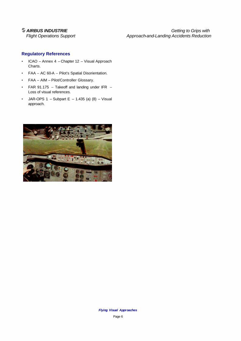
AIRBUS INDUSTRIE Getting to Grips with Flight Operations Support Approach-and-Landing Accidents Reduction
Flying Visual Approaches
Page 6
Regulatory References
• ICAO – Annex 4 – Chapter 12 – Visual Approach Charts.
• FAA – AC 60-A – Pilot’s Spatial Disorientation.
• FAA – AIM – Pilot/Controller Glossary.
• FAR 91.175 – Takeoff and landing under IFR – Loss of visual references.
• JAR-OPS 1 – Subpart E – 1.435 (a) (8) – Visual approach.
AIRBUS INDUSTRIE Getting to Grips with Flight Operations Support Approach-and-Landing Accidents Reduction
Chapter 8
Landing Techniques

AIRBUS INDUSTRIE Getting to Grips with Flight Operations Support Approach-and-Landing Accidents Reduction
Preventing Runway Excursions and Overruns
Page 1
Introduction Runway excursions include the following types of events:
• Veering off the runway during the landing roll;
or,
• Veering off the runway or taxiway when vacating the runway.
Runway overruns define events where the aircraft rollout extends beyond the end of the landing runway. This Briefing Note provides an overview of the factors involved in runway excursions and runway overruns, and suggests the development of corresponding prevention strategies and lines-of-defense. Statistical Data Runway excursions and overruns account for typically 20 % of all approach-and-landing accidents.
Event % of Events
Runway excursion 8 %
Runway overrun 12 %
Table 1
Runway Excursions and Overruns
Landing overruns represent 80 % of all observed runway overrun events (i.e., including runway overruns following a rejected takeoff).
Runway excursions and runway overruns may occur following all types of approaches:
• Visual;
• Non-precision; or,
• Precision approaches.
Runway excursions and overruns are observed regardless of daytime or nighttime conditions. Runway excursions and overruns often are associated with one or several of the following weather conditions:
• Low visibility or fog;
• Heavy rain (i.e., runway contaminated with standing water or runway slippery-when-wet);
• Cold weather operation (i.e., runway contaminated with slush or ice); and,
• Steady or gusting crosswind or tail wind component.
Runway excursion or overrun events also have been experienced with good weather and dry runway conditions. Factors Involved in Runway Excursions Runway excursions often are the result of the following operational factors and circumstances:
Weather factors:
• Runway condition (wet or contaminated by standing water, slush, snow or ice);
• Wind shear;
Approach-and-Landing Briefing Note
8.1 - Preventing Runway Excursions and Overruns

AIRBUS INDUSTRIE Getting to Grips with Flight Operations Support Approach-and-Landing Accidents Reduction
Preventing Runway Excursions and Overruns
Page 2
• Cross-wind component;
• Inaccurate information on wind and/or runway conditions; and,
• Reverse-thrust effect in crosswind and on contaminated runway.
Crew technique or decision factors:
• Incorrect crosswind landing techniques (e.g., drifting during the decrab and align phase, absence of decrab when landing in high crosswind conditions);
• Inappropriate differential braking by crew;
• Use of nose-wheel-steering tiller at high speed; and,
• Vacating the runway at an excessive speed. Systems factors:
• Asymmetric thrust (i.e., forward thrust on one side, reverse thrust on opposite side); or,
• Uncommanded differential braking. Factors Involved in Runway Overruns The following operational factors and circumstances are observed as recurring patterns, alone or in combination, in runway-overrun events:
Weather factors:
• Unanticipated runway condition (i.e., worse than anticipated);
• Inaccurate surface wind information; and,
• Unanticipated wind shear or tail wind component.
Performance factors:
• Incorrect assessment of landing distance following an in-flight malfunction or an MEL condition affecting:
− aircraft configuration (e.g., slats, flaps or roll spoilers);
− lift dumping (e.g., ground spoilers);or,
− braking capability (e.g., anti-skid);
• Incorrect assessment of landing distance for prevailing wind and runway conditions; and,
• Inoperative brake(s) not accounted for per MEL/DDG provision.
Crew technique or decision factors:
• Unstable approach path (steep and fast):
− Landing fast (up to V APP + 40 kt at runway threshold); and/or,
− Excessive height over threshold (up to 220 ft) resulting in a long landing;
• Absence of go-around decision, when warranted;
• Captain (PNF)’s decision to land following intention or initiation of go-around by first officer (PF);
• Long flare ( allowing the aircraft to float to bleed an excess-speed uses three times more runway than decelerating on the ground );
• Failure to arm ground spoilers (usually associated with thrust reversers being inoperative);
• Power-on touchdown (i.e., preventing automatic extension of ground spoilers);
• Failure to detect the non-deployment of ground spoilers (e.g., absence of related standard call);
• Forward throttle/thrust levers movement resulting in the premature retraction of ground spoilers and in the loss of autobrake;
AIRBUS INDUSTRIE Getting to Grips with Flight Operations Support Approach-and-Landing Accidents Reduction
Preventing Runway Excursions and Overruns
Page 3
• Bouncing and incorrect bounce recovery;
• Late braking (or late takeover from autobrake system, when required); and,
• Reduced braking efficiency while assuring directional control in crosswind conditions.
Systems factors:
• Loss of pedal braking; or,
• Antiskid malfunction resulting in aquaplaning (as evidenced by extensive spots on all affected tires).
Prevention Strategies and Lines-of-Defense The following prevention strategies and lines-of-defense should be implemented to address the factors involved in runway excursions and overruns:
Policies: • Define policy and procedures to promote the
readiness and commitment to go-around if the conditions for a safe landing are not achieved. (i.e., discouraging any attempt to rescue what is likely to be an hazardous landing);
• Define policy to ensure that inoperative brakes (“cold brakes”) are reported in the aircraft logbook and accounted for in accordance with the MEL;
• Define policy and procedures for rejected landing (i.e., bounce recovery);
• Define policy and procedures prohibiting landing beyond the published touchdown point (zone); and,
• Define policy encouraging a firm touchdown when operating on a runway contaminated with standing water or slush.
Standard operating procedures (SOPs): • Define criteria and callouts for stabilized
approach and define minimum stabilization heights (approach gates) depending on weather conditions (i.e., IMC versus VMC);
• Define task sharing and standard calls for final approach and rollout phases; and,
• Incorporate a crew callout for runway length remaining (e.g., xyz ft(m) runway remaining or xyw ft(m) to go), in low visibility conditions, based on:
− runway-lighting color change;
− runway-distance-remaining markers (as available); and/or,
− other available visual cues (such as runway or taxiway intersections).
Performance data: • Publish landing distances for various:
− type of braking (i.e., pedal braking or autobrake); and,
− runway conditions; and,
• Provide flight crews with landing distance corrections for runways featuring
− downhill slope; and/or,
− high elevation.
Crew techniques: • Publish procedures and provide training for
crosswind landing technique (i.e., crabbed approach with wings-level);
• Publish procedures and provide training for decrab technique, depending on crosswind component and runway condition (i.e., complete decrab, partial decrab or absence of decrab);
• Publish procedures for optimum use of autobrake system and thrust reversers on contaminated runway;
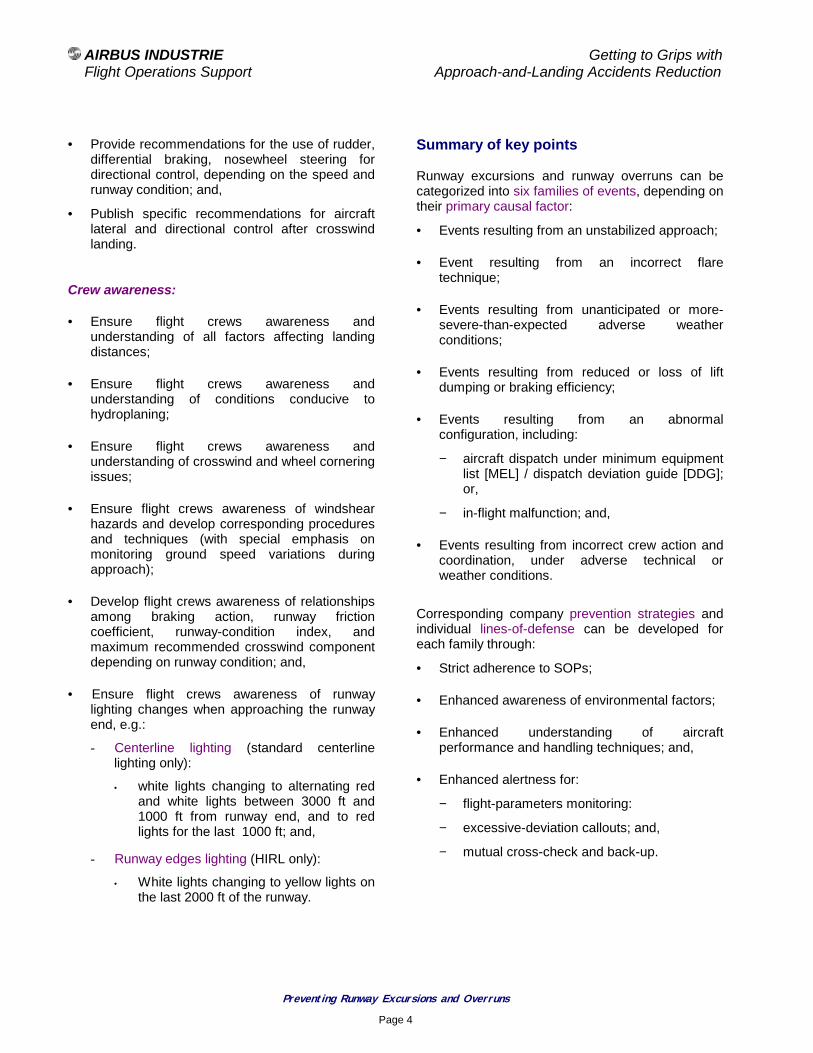
AIRBUS INDUSTRIE Getting to Grips with Flight Operations Support Approach-and-Landing Accidents Reduction
Preventing Runway Excursions and Overruns
Page 4
• Provide recommendations for the use of rudder, differential braking, nosewheel steering for directional control, depending on the speed and runway condition; and,
• Publish specific recommendations for aircraft lateral and directional control after crosswind landing.
Crew awareness: • Ensure flight crews awareness and
understanding of all factors affecting landing distances;
• Ensure flight crews awareness and understanding of conditions conducive to hydroplaning;
• Ensure flight crews awareness and understanding of crosswind and wheel cornering issues;
• Ensure flight crews awareness of windshear hazards and develop corresponding procedures and techniques (with special emphasis on monitoring ground speed variations during approach);
• Develop flight crews awareness of relationships among braking action, runway friction coefficient, runway-condition index, and maximum recommended crosswind component depending on runway condition; and,
• Ensure flight crews awareness of runway lighting changes when approaching the runway end, e.g.:
- Centerline lighting (standard centerline lighting only):
• white lights changing to alternating red and white lights between 3000 ft and 1000 ft from runway end, and to red lights for the last 1000 ft; and,
- Runway edges lighting (HIRL only):
• White lights changing to yellow lights on the last 2000 ft of the runway.
Summary of key points Runway excursions and runway overruns can be categorized into six families of events, depending on their primary causal factor:
• Events resulting from an unstabilized approach;
• Event resulting from an incorrect flare technique;
• Events resulting from unanticipated or more-severe-than-expected adverse weather conditions;
• Events resulting from reduced or loss of lift dumping or braking efficiency;
• Events resulting from an abnormal configuration, including:
− aircraft dispatch under minimum equipment list [MEL] / dispatch deviation guide [DDG]; or,
− in-flight malfunction; and,
• Events resulting from incorrect crew action and coordination, under adverse technical or weather conditions.
Corresponding company prevention strategies and individual lines-of-defense can be developed for each family through:
• Strict adherence to SOPs;
• Enhanced awareness of environmental factors;
• Enhanced understanding of aircraft performance and handling techniques; and,
• Enhanced alertness for:
− flight-parameters monitoring:
− excessive-deviation callouts; and,
− mutual cross-check and back-up.

AIRBUS INDUSTRIE Getting to Grips with Flight Operations Support Approach-and-Landing Accidents Reduction
Preventing Runway Excursions and Overruns
Page 5
Associated Briefing Notes The following specific Briefing Notes provide expanded information to supplement the above overview:
• 1.1 - Operating Philosophy - SOPs,
• 1.4 - Standard Calls,
• 6.4 - Bouncing Recovery – Rejected Landing,
• 7.1 - Flying Stabilized Approaches,
• 8.2 - The Final Approach Speed,
• 8.3 - Factors Affecting Landing Distances,
• 8.4 - Optimum Use of Braking Devices,
• 8.5 - Operation on Wet or Contaminated Runway,
• 8.6 - About Wind Information,
• 8.7 - Crosswind Landing.

AIRBUS INDUSTRIE Getting to Grips with Flight Operations Support Approach-and-Landing Accidents Reduction
The Final Approach Speed
Page 1
Approach-and-Landing Briefing Note
8.2 - The Final Approach Speed
Introduction Assuring a safe landing requires achieving a balanced distribution of safety margins between:
• The computed final approach speed; and,
• The resulting landing distance.
This Briefing Note provides an overview of:
• The definition of the final approach speed;
• Factors affecting the computation of this target speed; and,
• Rule applied for the combination of speed corrections.
Statistical Data The assessment of the final approach speed rarely is a factor in approach-and-landing incidents and accidents (even in runway overrun events), but approaching at a speed significantly faster than the computed target speed often is cited as a causal factor. Defining the Final Approach Speed The final approach speed is the speed to be maintained down to 50 ft over the runway threshold.
The final approach speed computation is the result of a tactical choice performed by the flight crew to assure the safest approach and landing for the prevailing conditions in terms of:
• Gross weight;
• Wind conditions;
• Flaps configuration (when several flaps configuration are certified for landing);
• Aircraft configuration (speed corrections for abnormal configurations);
• Icing conditions;
• Use of A/THR in SPD mode; or,
• Autoland.
The final approach speed V APP can be computed based on the reference threshold speed V REF or on the minimum selectable speed V LS (as available). V REF is defined as: V REF = 1.X (*) x (stall speed with full landing flaps* )
V LS is defined as: V LS = 1.X (*) x (stall speed in actual configuration* ) ( * ) 1.3 and minimum stall speed ( V S MIN ) on conventional aircraft models; or, 1.23 and stall speed under 1g ( V S 1g ) on fly-by-wire aircraft models.

AIRBUS INDUSTRIE Getting to Grips with Flight Operations Support Approach-and-Landing Accidents Reduction
The Final Approach Speed
Page 2
The final approach speed V APP can be determined based on V REF or V LS, as follows:
V APP = V REF + Corrections
The speed corrections on V REF account for:
• Aircraft configuration ( CONF CORR ):
− landing with less than full flaps; or,
− abnormal configuration;
• Operational factors:
− WIND CORR for wind component, gusty crosswind or suspected wind shear; and,
− + 5 kt for use of A/THR in SPD mode or if significant ice accretion is suspected.
or,
V APP = V LS + Increments + Corrections
The speed increments on V LS account for:
• Configuration conditions that are not included in the computation of the V LS.
The speed corrections on V LS account for:
• Operational factors only:
− WIND CORR for wind component, gusty crosswind or suspected wind shear; and,
− + 5 kt for use of A/THR in SPD mode or if significant ice accretion is suspected. (the speed correction for ice accretion is + 5 kt or + 10 kt, depending on aircraft model).
The resulting final approach speed V APP provides the best compromise between handling qualities (stall margin and/or maneuverability / controllability) and landing distance. For clarity and commonality among various Airbus models, the following overview and discussion refers only to the computation of V APP based on V REF.
Factors Affecting the Final Approach Speed The following speed corrections should are not be added, only the highest speed correction should be considered (unless otherwise stated in the applicable FCOM and QRH):
• Wind correction;
• Speed correction for ice accretion;
• Speed correction for the use of the A/THR in SPD mode or for autoland;
• Speed correction for forecast downburst / wind shear conditions.
The FCOM and QRH provide the rules applicable for the aircraft type and model.
Gross weight: Because V REF is referenced to the stall speed (V S MIN or V S 1g), V REF depends on the gross weight. The FCOM and QRH provide V REF tables for normal landings and overweight landings.
Wind conditions: The wind correction on the final approach speed provides an additional margin relative to the stall speed, to cope with speed excursions caused by turbulence and wind gradient. Airbus Industrie uses the following wind corrections (WIND CORR):
• A320/A330/A340 series:
− 1/3 of the headwind component (excluding the gust), limited to 15 kt;
• A310/A300-600:
− (1/3 of the tower average wind) or (the gust increment), whichever is higher, limited to 15 kt; or,
• A300B2/B4 and A300 FFCC:
− A graphical assessment based on the tower wind velocity and wind angle, limited to 15 kt.

AIRBUS INDUSTRIE Getting to Grips with Flight Operations Support Approach-and-Landing Accidents Reduction
The Final Approach Speed
Page 3
No wind correction is applied for tailwinds. On some aircraft models, the WIND CORR can be entered on the appropriate FMS page.
Flaps configuration: When several flap configurations are certified for landing, the reference threshold speed (for the selected configuration) is defined as:
V REF full flaps + ∆V REF.
In calm-wind conditions, in light-and-variable wind conditions and in light turbulence conditions, V REF + 5 kt is a typical target threshold speed.
Abnormal configuration: System malfunctions (such as the loss of one hydraulic system or the jamming of either slats or flaps) require a speed correction to restore:
• The stall margin (e.g., loss or jamming of slats and/or flaps); or,
• The controllability / maneuverability (e.g., loss of part of roll spoilers, V MCL limitation if applicable).
The speed corrections provided in the FCOM and QRH take into account all the consequential effects associated with the primary malfunction (i.e. no combination of speed corrections is required, unless otherwise stated and explained). The following rules are used to combine the different types of speed corrections:
• When two malfunctions affect the stall margin, both speed corrections are added;
• When two malfunctions affect the controllability / maneuverability , only the higher speed correction is considered;
• When one malfunction affects the stall margin and the other one affects the controllability / maneuverability, then only the higher speed correction is considered.
These rules are provided herein for enhanced understanding purposes only.
Use of A/THR in SPD mode: When using the A/THR in SPD mode during the final approach, a 5-kt speed correction on V REF should be added to account for the accuracy of the autothrottle/autothrust system in maintaining the final approach target speed. This speed correction ensures that a speed equal to or greater than V REF ( V LS ) is maintained at all times down to 50 ft over the runway threshold. CAT II / CAT III autoland: For CAT II approaches using the A/THR in SPD mode, CAT III approaches and autoland approaches (regardless of weather conditions), the 5-kt speed correction on V REF is required by certification. Ice accretion: When severe icing conditions are encountered, a 5-kt or 10-kt speed correction must be considered to account for the accretion of ice on the unheated surfaces of the aircraft. Downburst / Windshear: Downburst / windshear conditions may be anticipated based on;
• Pilot’s reports from preceding aircraft;
• Alerts issued by the airport low level windshear alert system (LLWAS); or,
• Data from a terminal Doppler weather radar (TDWR).
When downburst / windshear conditions are anticipated the landing should be delayed or the aircraft should divert to the destination alternate airport. If delayed landing or diversion is possible, a speed correction (usually up to 15 kt to 20 kt, based on the anticipated windshear) is recommended. Landing with less than full flaps is recommended to maximize the climb gradient capability; the final approach speed should be adjusted accordingly.
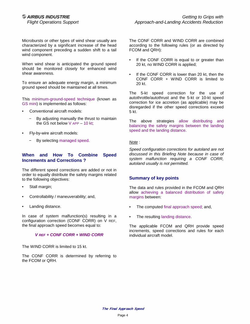
AIRBUS INDUSTRIE Getting to Grips with Flight Operations Support Approach-and-Landing Accidents Reduction
The Final Approach Speed
Page 4
Microbursts or other types of wind shear usually are characterized by a significant increase of the head wind component preceding a sudden shift to a tail wind component. When wind shear is anticipated the ground speed should be monitored closely for enhanced wind shear awareness. To ensure an adequate energy margin, a minimum ground speed should be maintained at all times.
This minimum-ground-speed technique (known as GS mini) is implemented as follows:
• Conventional aircraft models:
− By adjusting manually the thrust to maintain the GS not below V APP – 10 kt;
• Fly-by-wire aircraft models:
− By selecting managed speed. When and How To Combine Speed Increments and Corrections ? The different speed corrections are added or not in order to equally distribute the safety margins related to the following objectives:
• Stall margin;
• Controllability / maneuverability; and,
• Landing distance.
In case of system malfunction(s) resulting in a configuration correction (CONF CORR) on V REF, the final approach speed becomes equal to:
V REF + CONF CORR + WIND CORR
The WIND CORR is limited to 15 kt. The CONF CORR is determined by referring to the FCOM or QRH.
The CONF CORR and WIND CORR are combined according to the following rules (or as directed by FCOM and QRH):
• If the CONF CORR is equal to or greater than 20 kt, no WIND CORR is applied;
• If the CONF CORR is lower than 20 kt, then the CONF CORR + WIND CORR is limited to 20 kt.
The 5-kt speed correction for the use of autothrottle/autothrust and the 5-kt or 10-kt speed correction for ice accretion (as applicable) may be disregarded if the other speed corrections exceed 5 kt. The above strategies allow distributing and balancing the safety margins between the landing speed and the landing distance.
Note :
Speed configuration corrections for autoland are not discussed in this Briefing Note because in case of system malfunction requiring a CONF CORR, autoland usually is not permitted. Summary of key points The data and rules provided in the FCOM and QRH allow achieving a balanced distribution of safety margins between:
• The computed final approach speed; and,
• The resulting landing distance. The applicable FCOM and QRH provide speed increments, speed corrections and rules for each individual aircraft model.

AIRBUS INDUSTRIE Getting to Grips with Flight Operations Support Approach-and-Landing Accidents Reduction
The Final Approach Speed
Page 5
Associated Briefing Notes The following related Briefing Notes supplement the above discussion information:
• 7.1 - Flying Stabilized Approaches,
• 5.4 – Wind Shear Awareness,
• 8.1 - Preventing Runway Excursions and Overruns,
• 8.3 - Factors Affecting Landing Distances,
• 8.4 - Optimum Use of Braking Devices. Regulatory References
• FAA AC 120-29 – Criteria For Approval of Category I and Category II Landing Weather Mimima for FAR 121 Operators.
• FAA AC 120-28D – Criteria For Approval of Category III Weather Mimima for Takeoff, Landing and Rollout.

AIRBUS INDUSTRIE Getting to Grips with Flight Operations Support Approach-and-Landing Accidents Reduction
Factors Affecting Landing Distance
Page 1
Approach-and-Landing Briefing Note
8.3 - Factors Affecting Landing Distance
Introduction Runway overruns are involved in 12 % of approach-and-landing accidents. Understanding the factors affecting landing distance can contribute to reducing the number of runway-overrun events. This Briefing Note is supplemented by the Briefing Notes 8.2 – The Final Approach Speed and 8.4 - Optimum Use of Braking Devices . Defining the Landing Distance When referring to the landing distance, two definitions must be considered:
• The actual landing distance achieved to land and come to a complete stop (on a dry runway) after crossing the runway threshold at 50 ft.
The actual landing distance is used as reference for any in-flight assessment of the landing distance.
• The required landing distance is obtained by applying a regulatory factor to the actual landing distance.
The required landing distance is used for dispatch purposes (i.e., for selecting the destination, alternate and diversion airports).
Actual landing distances are demonstrated during certification flight tests without the use of thrust reversers.
Figure 1 and Figure 2 illustrate the actual and required landing distances, as defined by the European JAA / U.S. FAA and by the U.K. CAA.
Figure 1
Figure 2
Regulatory
Factor = 1.67
Actual Landing
Distance ( dry )
Regulatory
Factor = 1.92
Required Landing Distance - UK CAA
Required runway length (dry or wet) = Actual landing distance (dry) x 1.92
50 ft at threshold
Actual landing
Distance ( dry )
Dry or Wet runway
Required Landing Distance - JAA / FAA
Dry runway
+15% If wet
Wet runway
Required runway length (dry) = Actual landing distance (dry) x 1.67 Required runway length (wet) = Actual landing distance (dry) x
50 ft at threshold

AIRBUS INDUSTRIE Getting to Grips with Flight Operations Support Approach-and-Landing Accidents Reduction
Factors Affecting Landing Distance
Page 2
Factors Affecting Landing Distance The actual landing distance is affected by various operational factors; thus reducing the regulatory margins, this includes:
• Airfield elevation or low QNH condition (i.e., increased ground speed);
• Runway profile (i.e., downhill slope);
• Runway condition (i.e., nature and depth of contaminant; wet runway or runway contaminated by standing water, slush, snow or ice);
• Wind conditions (e.g., tailwind component);
• Type of braking used (i.e., pedal braking or autobrake, use of thrust reversers);
• Anti-skid failure;
• Incremental addition of all speed corrections on the final approach speed;
• Deviation from the final approach speed;
• Landing techniques (i.e., height and speed at threshold, thrust reduction and flare technique);
• Deviations from SOPs (e.g., failure to arm ground spoilers);
• MEL conditions (i.e., thrust reversers, brake unit, anti-skid or ground spoilers inoperative); and,
• In-flight system malfunctions resulting in an increased final approach speed, or affecting the lift-dumping or braking capability.
These factors are discussed hereafter and illustrated in Figure 4. Airfield elevation: Airfield elevation or a corresponding low QNH value results in a higher TAS and ground speed and, thus, in a greater landing distance. At 1000-ft airfield elevation or at sea level with an equivalent pressure altitude (i.e. with a low QNH of 980 hPa), the landing distance is increased by 5 % to 10 % (factor 1.05 to 1.10).
Runway profile (sl ope): All Airbus aircraft models are certified for landing operation on runways not exceeding a mean downhill slope of 2%. The applicable operational regulation (JAR-OPS) requires to account for the runway slope only when the downhill slope exceeds 2%. Therefore, the landing distance tables published in the FCOM and QRH are applicable without correction within the certified envelope. The following information is provided for enhanced understanding only. The runway profile (i.e., downhill slope) affects the landing distance without autobrake. A 1 % downhill slope increases the landing distance without autobrake by 2 % (factor 1.02). When autobrake is used, the selected deceleration rate is achieved regardless of the runway slope. Runway conditions: Runway contamination increases the rolling drag (i.e., the displacement drag) and the aerodynamic drag (i.e., the impingement drag) but also decreases the braking efficiency. The following landing distance factors are typical on a contaminated runway:
Runway Condition Factors
Wet 1.3 to 1.4
Standing water or slush 2.0 to 2.3
Compacted snow 1.6 to 1.7
Ice 3.5 to 4.5
Table 1
Landing Distance Factors - Contaminated Runway

AIRBUS INDUSTRIE Getting to Grips with Flight Operations Support Approach-and-Landing Accidents Reduction
Factors Affecting Landing Distance
Page 3
Briefing Note 8.5 - Landing on Contaminated Runway provides expanded and illustrated information for operation on runway contaminated with standing water, slush, snow or ice. Wind conditions: In accordance with certification requirements and operational regulations, the published landing distance factors account for:
• 50 % of the head wind component; and,
• 150 % of the tail wind component. Note :
In case of gusting crosswind, a tailwind component may exist but is not reported. This condition may be undetected and therefore be not accounted for. Type of braking: Actual landing distances are demonstrated during certification flight tests using the following technique:
• Flying an optimum flight segment from 50 ft over the runway threshold down to the flare point;
• Performing a firm touchdown; and,
• Using full pedal braking, upon main landing gear touchdown.
The published actual landing distances seldom can be achieved in revenue service. The landing distances published for automatic landing with use of autobrake provide more achievable references for line operations. Speed Over Runway Threshold: The actual landing distance ( LD ) is a direct function of the kinetic energy ( E ) to be absorbed. For an aircraft crossing the runway threshold at a given gross-weight ( GW ) and at the final approach speed ( V APP ), the kinetic energy is:
E = ½ .GW.( V APP )
2
At given gross weight ( GW ), any increment of or deviation from V APP results in a corresponding increase of energy ( ∆E ) such that:
∆E ( in % ) = 2 x ∆ VAPP ( in % )
The landing distance LD being a direct function of the energy E, the corresponding increase in landing distance ( ∆LD ) can be expressed also as:
∆LD ( in % ) = 2 x ∆ VAPP ( in % )
In pilot’s terms :
• a 10 % increase in final approach speed;
results in,
• a 20 % increase in landing distance.
Note :
The above rule assumes a normal flare and touchdown (i.e., not allowing the aircraft to float to bleed off the excess speed). Height over threshold: Crossing the runway threshold at 100 ft results in an increase of the landing distance of typically 1000 ft or 300 m, regardless of the runway condition and aircraft model.
Figure 3
100 ft at threshold
1000 ft/300 m
50 ft at threshold

AIRBUS INDUSTRIE Getting to Grips with Flight Operations Support Approach-and-Landing Accidents Reduction
Factors Affecting Landing Distance
Page 4
Flare technique: Performing a long flare (i.e., allowing the aircraft to float to bleed off an excessive speed) further increases the landing distance. For example, a 5 % increase (excess) of the final approach speed increases the landing distance by:
• 10 %, if a normal flare and touchdown is performed (i.e., deceleration on the ground); or,
• 30 %, if a long flare is performed (i.e., deceleration while airborne).
Performing a power-on touchdown in an attempt to lessen an excessive rate-of-descent or to smooth out the touchdown results in:
• A long flare; and,
• The inhibition of the automatic extension of ground-spoilers.
This increases the risk of bouncing upon touchdown and of a subsequent hard landing. Ground spoiler not armed: Failure to arm the ground spoilers (usually in conjunction with thrust reversers being inoperative) is frequently a causal factor in runway overruns. The ground spoilers extend automatically when reverse thrust is selected (regardless of whether the ground spoilers are armed or not); this design feature must not be relied upon for extension of ground spoilers. Ground spoilers must be armed per SOPs. Failure to arm the ground spoilers results in a typical landing distance factor of 1.3 (1.4 if thrust reversers are inoperative). The automatic extension of ground spoilers should be monitored and announced by calling Ground Spoilers or No Spoilers.
Note: On A300/A310 series, if ground spoilers do not deploy automatically, the PF can manually extend the ground spoilers using the speed brakes lever.
Delaying the derotation (i.e., the nose landing gear touchdown) maintains a higher lift on main landing gears for longer, resulting in less load on the main landing gears and, hence, in less braking efficiency. This also delays the spin-up signal from the nose-wheels; this signal is required for the optimum operation of the anti-skid system. MEL conditions: When operating under the provision of the MEL for an item affecting the landing speed, the lift-dumping or the braking capability, the applicable landing speed correction and landing distance factor must be accounted for. Systems malfunctions: System malfunctions, such as an hydraulic system low pressure, may result in multiple effects on the landing speed and landing distance, such as:
• Landing speed correction due to slats or flaps inoperative (i.e., restoring the stall margin);
• Landing speed correction due to loss of roll spoilers (i.e., restoring the maneuverability);
• Landing distance factor due to loss of ground spoilers (i.e., loss of lift dumping capability); and,
• Landing distance factor due to loss of normal braking system (i.e., reduced braking capability).
The FCOM and QRH provide the applicable final approach speed corrections and landing distance factors for all malfunctions (including their consequential effects).

AIRBUS INDUSTRIE Getting to Grips with Flight Operations Support Approach-and-Landing Accidents Reduction
Factors Affecting Landing Distance
Page 5
Combining Landing Distance Factors The landing distance factors provided in the FCOM and QRH take into account all the consequential effects associated with the primary malfunction. No combination of landing distance factors is needed, unless otherwise stated and explained. Nevertheless, understanding the rules used to combine landing distance factors provides an enhanced understanding of the achievable landing distance. Landing distance factors result from:
• A landing speed correction (e.g., because of a failure affecting the stall margin or maneuverability / controllability); or,
• A reduced lift-dumping or braking capability (e.g., because of a failure affecting ground spoilers, anti-skid or brakes).
Briefing Note 8.2 - The Final Approach Speed provides the rules used for the combination of landing speed corrections. The following rules are used to combine the different types of landing distance factors:
• If landing speed corrections are added (as described in Briefing Note 8.2), the corresponding landing distance factors are multiplied;
• If only the higher speed correction is retained, then only the higher landing distance factor is considered; or,
• When one or both of the two landing distance factors is (are) related to lift-dumping or braking, both landing-distance factors are multiplied.
Summary of key points When assessing the landing distance, the following factors should be accounted for and combined, as specified in the applicable FCOM / QRH:
• Dispatch conditions, as applicable (dispatch under minimum equipment list [MEL] / dispatch deviation guide [DDG] );
• In-flight failures, as applicable;
• Weather conditions (e.g., icing conditions / ice accretion);
• Wind conditions (i.e., wind component and gust, suspected wind shear);
• Airfield elevation;
• Runway slope (i.e., if down hill);
• Runway condition (i.e., nature and depth of contaminant); and,
• Use of braking devices (e.g., thrust reversers, autobrake).
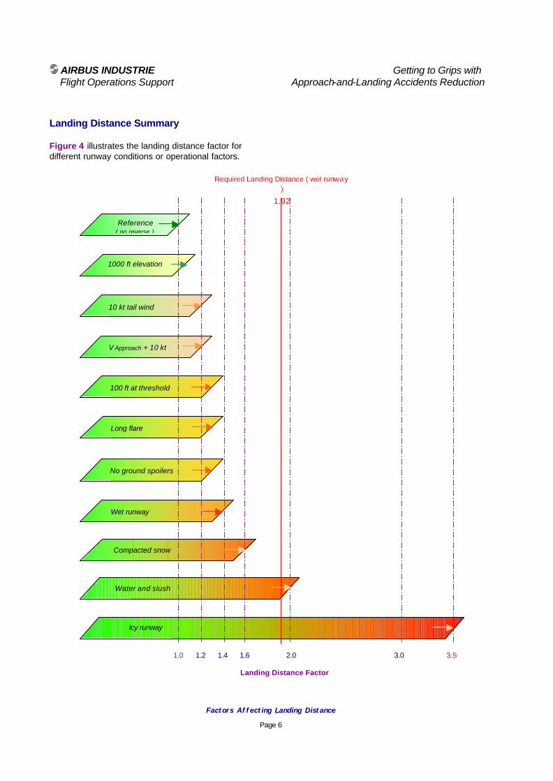
AIRBUS INDUSTRIE Getting to Grips with Flight Operations Support Approach-and-Landing Accidents Reduction
Factors Affecting Landing Distance
Page 6
Landing Distance Summary Figure 4 illustrates the landing distance factor for different runway conditions or operational factors.
1000 ft elevation
Reference ( no reverse )
Icy runway
Water and slush
Wet runway
Compacted snow
V Approach + 10 kt
100 ft at threshold
Long flare
No ground spoilers
10 kt tail wind
1.0 1.2 1.4 1.6 2.0 3.0 3.5
Landing Distance Factor
Required Landing Distance ( wet runway )
1.92
AIRBUS INDUSTRIE Getting to Grips with Flight Operations Support Approach-and-Landing Accidents Reduction
Factors Affecting Landing Distance
Page 7
Associated Briefing Notes The following Briefing Notes provide expanded information on braking issues, on dry, wet or contaminated runway:
• 1.4 - Standard Calls,
• 6.4 - Bounce Recovery – Rejected Landing,
• 8.2 - The Final Approach Speed,
• 8.4 - Optimum Use of Braking Devices,
• 8.5 - Landing on Contaminated Runway. Regulatory References • ICAO – Preparation of an Operations Manual
(Doc 9376),
• FAR 121.97 or 121.117 – Airports: Required Data,
• FAR 121 Subpart I – Airplane Performance Operating Limitations:
− FAR 121.171 – Applicability,
− FAR 121.195 – Airplanes: Turbine engine-powered: Landing limitations: Destination airports,
− FAR 121.197 – Airplanes: Turbine engine-powered: Landing limitations: Alternate airports,
• FAA – AC 91-6A and 91-6B – Water, Slush and Snow on the Runway.
• JAR-OPS 1.515 – Landing – Dry Runways,
• JAR-OPS 1.520 – Landing – Wet and Contaminated Runways,
• UK CAA – AIC 11/98 – Landing Performance of Large Transport Aeroplanes,
• UK CAA – AIC 61/99 – Risks and factors Associated with Operations on Runways Affected by Snow, Slush or Water.

AIRBUS INDUSTRIE Getting to Grips with Flight Operations Support Approach-and-Landing Accidents Reduction
Optimum Use of Braking Devices
Page 1
Approach-and-Landing Briefing Note
8.4 - Optimum Use of Braking Devices
Introduction To ensure an optimum use of braking devices, the following aspects must be understood:
• Design and operation of each braking device (i.e., ground spoilers, brakes and thrust reversers);
• Distribution of stopping forces during landing roll;
• Type of braking required to achieve a desired stopping distance;
• Factors affecting the optimum use of braking devices; and,
• Applicable operational guidelines. Statistical Data Runway excursions and overruns account for 20 % of all approach-and-landing serious incidents and accidents. Slowed or delayed braking action was a causal factor in 45 % of these events. Landing overruns represent 80 % of all observed overrun events (i.e., including runway overruns following a rejected takeoff). The use of braking devices is only one among several causal factors resulting in a runway excursion or overrun.
Braking Devices Overview The following braking devices are used to decelerate the aircraft and bring it to a complete stop:
• Ground spoilers;
• Wheel brakes (including anti-skid and autobrake systems); and,
• Thrust reverser system.
Ground spoilers: Ground spoilers deploy automatically upon main landing gear touchdown (if armed) or upon selection of the thrust reversers.
Ground spoilers provide two distinct aerodynamic effects, as illustrated by Figure 1 :
• Increased aerodynamic drag, which contributes to aircraft deceleration;
• Lift dumping, which increases the load on the wheels and increases the wheel-brakes efficiency.

AIRBUS INDUSTRIE Getting to Grips with Flight Operations Support Approach-and-Landing Accidents Reduction
Optimum Use of Braking Devices
Page 2
Wheel brakes: Braking action results from the friction force between the tires and the runway surface. This friction force depends on several parameters:
• Aircraft speed;
• Wheel speed (i.e., free rolling, skidding or locked wheel);
• Runway condition (i.e., nature and depth of contaminant);
• Tire condition and pressure (i.e., friction surface);
• The load applied on the wheel (i.e., the friction force depends on the load applied on the wheel and on the runway braking coefficient);
• The number of operative brakes ( MEL status, as applicable).
Anti-skid systems are designed to maintain the wheel skidding factor (also called the slip ratio) close to the point providing the maximum friction force, approximately 10 % on a scale going from 0 % (free rolling) to 100 % (locked wheel), as illustrated by Figure 2.
Figure 2
Tire Braking Force versus Slip Ratio With anti-skid operative, full pedal braking results in a deceleration rate of 8 knots-per-second to 10 knots-per-second on a dry runway.
Tire Braking Force
0
10
20
30
40
50
60
70
80
90
100
0 5 8 10 15 20 30 40 50 60 70 80 90 100
Slip Ratio ( % )
Forc
e ( %
)
Free rolling wheel
Antiskid activation
Locked wheel
Figure 1
Maximizing Weight-on-Wheels and Aerodynamic Drag
Negligible Weight on Main Wheels
Touchdown V APP ( V LS )
60 % Weight on Main Wheels
Nose Wheel Down
85 % Weight on Main Wheels
Ground Spoilers Extended
130 % Drag Increase from
Ground Spoilers

AIRBUS INDUSTRIE Getting to Grips with Flight Operations Support Approach-and-Landing Accidents Reduction
Optimum Use of Braking Devices
Page 3
Autobrake System: Autobrake system is designed to provide a selected deceleration rate for enhanced passenger comfort, typically between 3 knots-per-second and 6 knots-per-second, depending on the selected mode. When a low deceleration rate ( i.e., LOW mode ), the brake pressure is applied after a specific time delay to give priority to the thrust-reversers effect high speed (Figure 3). Thrust reversers: Thrust reversers provide a deceleration force that is independent from the runway condition. Thrust reverse efficiency is higher at high speed (as illustrated by Figure 3); thrust reversers therefore should be selected as early as possible after touchdown (in accordance with applicable SOPs). Thrust reversers should be returned to reverse idle at low speed ( to prevent engine stall and/or foreign objet damage caused by exhaust gas re-ingestion ) and stowed at taxi speed. Nevertheless, maximum reverse thrust can be maintained down to a complete stop in an emergency.
Runway conditions Runway contamination increases:
• Impingement drag (i.e., the drag resulting from the spray of contaminant striking the landing gear and airframe); and,
• Rolling drag (i.e., the displacement drag).
Runway contamination also affects the braking efficiency. The following landing distance factors are typical on wet or contaminated runway :
Runway Condition Factors
Wet 1.3 to 1.4
Standing water or slush 2.0 to 2.3
Compacted snow 1.6 to 1.7
Ice 3.5 to 4.5
Table 1
Landing Distance Factors
Wet or Contaminated Runway
Reverse(d) thrust t t t t
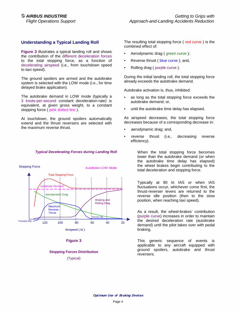
AIRBUS INDUSTRIE Getting to Grips with Flight Operations Support Approach-and-Landing Accidents Reduction
Optimum Use of Braking Devices
Page 4
Understanding a Typical Landing Roll Figure 3 illustrates a typical landing roll and shows the contribution of the different deceleration forces to the total stopping force, as a function of decelerating airspeed (i.e., from touchdown speed to taxi speed). The ground spoilers are armed and the autobrake system is selected with the LOW mode (i.e., for time delayed brake application). The autobrake demand in LOW mode (typically a 3 knots-per-second constant deceleration-rate) is equivalent, at given gross weight, to a constant stopping force ( pink dotted line ). At touchdown, the ground spoilers automatically extend and the thrust reversers are selected with the maximum reverse thrust.
The resulting total stopping force ( red curve ) is the combined effect of:
• Aerodynamic drag ( green curve );
• Reverse thrust ( blue curve ); and,
• Rolling drag ( purple curve ).
During the initial landing roll, the total stopping force already exceeds the autobrake demand. Autobrake activation is, thus, inhibited:
• as long as the total stopping force exceeds the autobrake demand; or,
• until the autobrake time delay has elapsed. As airspeed decreases, the total stopping force decreases because of a corresponding decrease in:
• aerodynamic drag; and,
• reverse thrust (i.e., decreasing reverse efficiency).
When the total stopping force becomes lower than the autobrake demand (or when the autobrake time delay has elapsed) the wheel brakes begin contributing to the total deceleration and stopping force.
Typically at 80 kt IAS or when IAS fluctuations occur, whichever come first, the thrust-reverser levers are returned to the reverse idle position (then to the stow position, when reaching taxi speed). As a result, the wheel-brakes’ contribution (purple curve) increases in order to maintain the desired deceleration rate (autobrake demand) until the pilot takes over with pedal braking. This generic sequence of events is applicable to any aircraft equipped with ground spoilers, autobrake and thrust reversers.
Typical Decelerating Forces during Landing Roll
Airspeed ( kt )
Stopping Force
120 100 80 60 40 20
Braking and Rolling Drag
Total Stopping Force
Autobrake LOW Mode
Aerodynamic Drag
Maximum Reverse Thrust
Autobrake Demand
Reverse Idle
Forward Idle
Figure 3
Stopping Forces Distribution
(Typical)

AIRBUS INDUSTRIE Getting to Grips with Flight Operations Support Approach-and-Landing Accidents Reduction
Optimum Use of Braking Devices
Page 5
How do Ground Spoilers, Thrust Reversers and Brakes Contribute to Stop the Aircraft? Figure 4 illustrates the respective contributions of the different braking devices to the total stopping energy, as a function of the achieved or desired stopping distance.
Figure 4 provides the following information:
• For a given braking mode (i.e., pedal braking or autobrake mode):
− Achieved stopping distance ( landing roll );
• For a desired or required stopping distance:
− Required type of braking (e.g., pedal braking or autobrake mode).
Figure 4
Stopping Energy Distribution versus Stopping Distance
(Typical)
10
20
30
40
50
60
70
80
% of Total Stopping Energy
1000 2000 3000
Stopping Distance (m)
Braking and Rolling Drag
Aerodynamic Drag
Maximum Reverse Thrust
Maximum pedal braking ( typically 8 to 10 kt/s )
No Braking
Autobrake MED ( typically 6 kt/s )
Autobrake LOW ( typically 3 kt/s )
Max Landing Weight - Sea Level - ISA - Dry runway
4000

AIRBUS INDUSTRIE Getting to Grips with Flight Operations Support Approach-and-Landing Accidents Reduction
Optimum Use of Braking Devices
Page 6
Factors Affecting Optimum Braking The following factors often are involved in runway excursions (i.e., aircraft veering off the runway or taxiway), or in runway overruns:
• Failure to arm ground spoilers, with thrust reversers deactivated (e.g., reliance on thrust reverser signal for ground spoilers extension);
• Failure to use any braking devices (i.e., use of the inappropriate nose high “aerodynamic braking” technique);
• Asymmetric thrust (i.e. one engine being above idle level in forward thrust or one engine failing to go into reverse thrust);
• Brake unit inoperative (i.e., brake unit reported as “cold brake” for several flights, without corresponding MEL entry);
• Anti-skid tachometer malfunction;
• Absence of switching or late switching from NORM braking to ALTN braking or to emergency braking in case of abnormal braking;
• Late selection of thrust reversers;
• Absence of takeover or late takeover from autobrake, when required;
• Inadequate crosswind landing technique; and,
• Incorrect differential braking technique.
Operational Guidelines and Key Points Strict adherence to the following operational standards and guidelines ensures optimum braking during the landing roll:
• Arm ground spoilers;
• Arm autobrake with the most appropriate mode for prevailing conditions (short runway, runway with downhill slope, low visibility, contaminated runway);
• Select thrust reversers as soon as possible with maximum reverse thrust ( this increases safety on dry and wet runway, and is mandatory on runway contaminated with standing water, slush, snow or ice );
• Monitor and call ground spoilers extension;
• Monitor and call autobrake operation;
• Be ready to take over from autobrake, if required;
• Monitor engine operation in reverse thrust (e.g., increasing EGT and/or evidence of surge);
• Monitor airspeed indication and return reverse levers to the reverse idle position at the published indicated airspeed or when airspeed fluctuations occur, whichever come first;
• If required, use maximum pedal braking; and,
• Do not stop braking until assured that the aircraft will stop within the remaining runway length.

AIRBUS INDUSTRIE Getting to Grips with Flight Operations Support Approach-and-Landing Accidents Reduction
Optimum Use of Braking Devices
Page 7
Associated Briefing Notes The following Briefing Notes provide expanded information on landing performance and techniques:
• 8.3 - Factors Affecting Landing Distances,
• 8.5 - Landing on Wet and Contaminated Runway,
• 8.7 - Crosswind Landing. Regulatory References
• ICAO – Preparation of an Operations Manual (Doc 9376),
• FAR 121.97 or 121.117 – Airports: Required Data,
• FAR 121 Subpart I – Airplane Performance Operating Limitations:
− FAR 121.171 – Applicability,
− FAR 121.195 – Airplanes: Turbine engine-powered: Landing limitations: Destination airports,
− FAR 121.197 – Airplanes: Turbine engine-powered: Landing limitations: Alternate airports,
• FAA – AC 916A and 91-6B,
• JAR-OPS 1.515 – Landing – Dry Runways,
• JAR-OPS 1.520 – Landing – Wet and Contaminated Runways,
• UK CAA – AIC 11/98 – Landing Performance of Large Transport Aeroplanes,
• UK CAA – AIC 61/99 – Risks and factors Associated with Operations on Runways Affected by Snow, Slush or Water.
AIRBUS INDUSTRIE Getting to Grips with Flight Operations Support Approach-and-Landing Accidents Reduction
Landing on Wet or Contaminated Runway
Page 1
Approach-and-Landing Briefing Note
8.5 - Landing on Wet or Contaminated Runway
Introduction Factors associated with landing on a wet runway or on a runway contaminated with standing water, slush, snow or ice should be assessed carefully before beginning the approach. This Briefing Note provides an overview and discussion of operational factors involved in planning and conducting a landing on a wet or contaminated runway. Statistical Data Runway condition, alone or in combination with adverse crosswind, is a circumstantial factor in 75 % of runway excursions or runway overruns at landing. Runway contamination with standing water, slush, snow or ice is a causal factor in 18 % of all landing accidents. Defining the Runway Condition The European JAA defines the runway condition as follows:
Dry runway: A dry runway is “one that is neither wet nor contaminated”. This “includes paved runways that have been specially prepared with grooved or porous pavement and maintained to retain an effectively dry braking action, even when moisture is present”.
Damp runway: A runway is considered damp “when the surface is not dry, but when the moisture on the surface does not give a shiny appearance”.
Wet runway: A runway is considered to be wet “when the surface is covered with water, or equivalent, not exceeding 3 mm - or when there is sufficient moisture on the runway surface to cause it to appear reflective (shiny) - but without significant areas of standing water”.
Contaminated runway: A runway is considered to be contaminated “when more than 25 % of the runway surface (whether in isolated areas or not) - within the required length and width being used – is covered by either:
• Standing water, more than 3 mm (1/8 inch) deep;
• Slush (i.e., water saturated with snow) or loose snow, equivalent to 3 mm (1/8 inch) - or more - of water;
• Snow which has been compressed into a solid mass which resists further compression and will hold together or break into lumps if picked up (i.e., compacted snow); or,
• Ice, including wet ice contaminant (runway friction coefficient 0.05 or below)”.
Uncleaned rubber deposits in the touchdown zone result in the runway surface to be slippery-when-wet.

AIRBUS INDUSTRIE Getting to Grips with Flight Operations Support Approach-and-Landing Accidents Reduction
Landing on Wet or Contaminated Runway
Page 2
Factors and Effects Braking action: The presence of fluid contaminant (i.e., standing water, slush or loose snow) or hard contaminant (i.e., compacted snow or ice) on the runway adversely affects the braking performance (stopping force) by:
• Reducing the friction force between the tires and the runway surface.
The reduction of friction force depends on the following factors:
− tire tread condition (wear) and inflation pressure;
− type of runway surface; and,
− anti-skid system performance.
• Creating a fluid layer between the tires and the runway surface, thus reducing the contact area and creating a risk of hydroplaning (i.e., complete loss of contact and friction between the tires and the runway surface).
Fluid contaminants (such as standing water, slush or loose snow) also positively contribute to the stopping force at landing by:
• Resisting to the wheels forward movement, thus causing a displacement drag;
• Creating a spray pattern that strikes the landing gears and airframe, thus causing an impingement drag.
Certification regulations require the spray pattern to be diverted away from engine air inlets to prevent affecting engine performance.
The braking action is the net effect of the above stopping forces (as illustrated by Figure 1 and Figure 2). Hydroplaning (aquaplaning): Hydroplaning occurs when the tire cannot squeeze any more of the fluid contaminant layer between its tread and the runway surface; the tire lifts from the runway surface and surfs the wave of water.
Hydroplaning results in a partial or total reduction of contact surface between the tire and the runway and in a corresponding loss of friction coefficient. Main-wheels and nose-wheels equally can be affected by hydroplaning, thus affecting the braking performance and the effectiveness of the nose-wheel-steering. Hydroplaning always occurs in some degree when operating on a fluid-contaminated runway. The potential for severe hydroplaning directly depends on the following factors:
• Absence of runway surface roughness and drainage (e.g., transverse saw-cut grooves);
• Thickness and nature (e.g., water or slush) of the fluid contaminant layer;
• Tire inflation pressure;
• Ground speed; and,
• Antiskid operation (e.g., locked-wheel case). A minimum hydroplaning speed can be defined for each aircraft type and runway contaminant. Hydroplaning may occur at touchdown, preventing the wheels from spinning and from sending the wheel-rotation-signal to various aircraft systems. Performing a firm touchdown can prevent hydroplaning at touchdown and ensure rotation of main-landing-gear wheels.
Directional control: On contaminated runway, directional control should be maintained using rudder pedals (do not use nose-wheel-steering tiller until aircraft has slowed down to taxi speed). On wet or contaminated runway, use of nose-wheel-steering above taxi speed may result in hydroplaning of nose-wheels, hence in loss of nose-wheels cornering force and, thus, in loss of directional control. If differential braking is necessary, pedal braking should be applied on the required side and be completely released on the opposite side, to regain tire cornering.

AIRBUS INDUSTRIE Getting to Grips with Flight Operations Support Approach-and-Landing Accidents Reduction
Landing on Wet or Contaminated Runway
Page 3
Briefing Note 8.7 - Crosswind Landing provides expanded information on directional control under crosswind conditions.
Assessing Landing Distance Landing distances are provided in the FCOM and QRH for a dry runway and for the following runway conditions and contaminants:
• Wet;
• 6.3 mm (1/4 inch) standing water;
• 12.7 mm (1/2 inch) standing water;
• 6.3 mm (1/4 inch) slush;
• 12.7 mm (1/2 inch) slush;
• Compacted snow; and,
• Ice. Actual landing distances are provided for all runway conditions and assume:
• An even distribution of the contaminant;
• The use of full pedal braking beginning at touchdown; and,
• An operative anti-skid system. Autoland landing distances using autobrake are published for all runway conditions. In addition, correction factors (in %) are provided to account for the following effects:
• Airport elevation:
− Typically, + 5 % per 1000 ft;
• Wind component:
− Typically, + 10 % per 5 kt tailwind component;
− Typically, – 2.5 % per 5 kt headwind component; and,
• Thrust reversers effect:
− Thrust reverser effect depends on runway condition and type of braking, as illustrated by Figure 4.
Understanding Stopping Forces during Landing Roll
Figure 1 shows the distribution of the respective stopping forces, as a function of the decreasing airspeed, during a typical landing roll using autobrake in LOW mode and maximum reverse thrust ( see also Briefing Note 8.4 - Optimum Use of Braking Devices ).
The total stopping force is the combined effect of:
• Aerodynamic drag, including the impingement drag ( green curve );
Note :
The term aerodynamic drag refers to the drag of the airplane during the rollout (including the impingement drag, on fluid contaminated runway), not to the (inappropriate) technique of keeping the nose high to (supposedly) increase the overall aerodynamic stopping force.
• Reverse thrust ( blue curve ); and,
• Braking and rolling drag, including the displacement drag ( red curve ).
Figure 1
Typical Decelerating Forces during Landing Roll
Airspeed ( kt )
Stopping Force
140 120 100 80 60 40 20
Braking and Rolling Drag
Total Stopping Force
Autobrake LOW Mode
Aerodynamic Drag
Maximum Reverse Thrust
Autobrake Demand

AIRBUS INDUSTRIE Getting to Grips with Flight Operations Support Approach-and-Landing Accidents Reduction
Landing on Wet or Contaminated Runway
Page 4
Stopping Energy Distribution on Contaminated Runway Figure 2 illustrates the contribution to the total stopping energy of the different braking devices, as a function of the desired or achieved stopping distance, on a runway contaminated with ¼ inch of water. Figure 2 provides:
• The stopping distance ( landing roll ) achieved for a given type of braking (i.e., pedal braking or selected autobrake mode);
or,
• The necessary type of braking (i.e., pedal braking or selected autobrake mode) for a desired or required stopping distance.
The contribution of the different braking devices to the total stopping energy on a runway contaminated with ¼ inch of standing water can be compared to their respective contributions on a dry runway, as illustrated in Briefing Note 8.4 – Optimum Use of Braking Devices, Figure 4 ):
• The contribution of the aerodynamic drag increases due to the additional impingement drag;
• The contribution of the braking and rolling drag (i.e., net effect of braking force and displacement drag) decreases;
• The contribution of the thrust reverser stopping force is independent from the runway condition.
Given Aircraft - Maximum Landing Weight - V APP – Both Reversers Sea Level - ISA – ¼ Inch Water
Stopping ( Landing ) Distance (m)
Figure 2
No braking
0
10
20
30
40
50
60
70
80
% of Stopping Energy
1000 2000 3000
Maximum pedal braking ( typically – 5 kt/s )
Autobrake medium ( typically – 4 kt/s )
Autobrake low ( typically – 3 kt/s )
4000
Braking and Rolling Drag
Aerodynamic Drag
Maximum Reverse Thrust
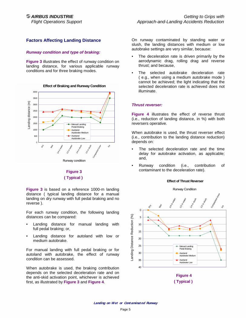
AIRBUS INDUSTRIE Getting to Grips with Flight Operations Support Approach-and-Landing Accidents Reduction
Landing on Wet or Contaminated Runway
Page 5
Factors Affecting Landing Distance
Runway condition and type of braking: Figure 3 illustrates the effect of runway condition on landing distance, for various applicable runway conditions and for three braking modes. Figure 3 ( Typical )
Figure 3 is based on a reference 1000-m landing distance ( typical landing distance for a manual landing on dry runway with full pedal braking and no reverse ). For each runway condition, the following landing distances can be compared:
• Landing distance for manual landing with full pedal braking; or,
• Landing distance for autoland with low or medium autobrake.
For manual landing with full pedal braking or for autoland with autobrake, the effect of runway condition can be assessed. When autobrake is used, the braking contribution depends on the selected deceleration rate and on the anti-skid activation point, whichever is achieved first, as illustrated by Figure 3 and Figure 4.
On runway contaminated by standing water or slush, the landing distances with medium or low autobrake settings are very similar, because:
• The deceleration rate is driven primarily by the aerodynamic drag, rolling drag and reverse thrust; and because,
• The selected autobrake deceleration rate ( e.g., when using a medium autobrake mode ) cannot be achieved; the light indicating that the selected deceleration rate is achieved does not illuminate.
Thrust reverser: Figure 4 illustrates the effect of reverse thrust (i.e., reduction of landing distance, in %) with both reversers operative. When autobrake is used, the thrust reverser effect (i.e., contribution to the landing distance reduction) depends on:
• The selected deceleration rate and the time delay for autobrake activation, as applicable; and,
• Runway condition (i.e., contribution of contaminant to the deceleration rate).
Figure 4 ( Typical )
Effect of Braking and Runway Condition
0
500
1000
1500
2000
2500
3000
3500
4000
Dry
Wet
1/4
in w
ater
1/2
in w
ater
1/4
in s
lush
1/2
in s
lush
Com
pact
ed s
now Ice
Runway condition
Land
ing
dist
ance
(m
)
Manual LandingPedal BrakingAutolandAutobrake MediumAutolandAutobrake Low
Effect of Thrust Reverser
0
5
10
15
20
25
30
35
40
Dry
Wet
1/4
in w
ater
1/2
in w
ater
1/4
in s
lush
1/2
in s
lush
Com
pact
ed s
now
Ice
Runway Condition
Lan
ding
Dis
tanc
e R
educ
tion
(%)
Manual LandingPedal Braking
AutolandAutobrake Medium
AutolandAutobrake Low
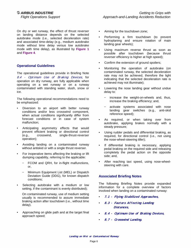
AIRBUS INDUSTRIE Getting to Grips with Flight Operations Support Approach-and-Landing Accidents Reduction
Landing on Wet or Contaminated Runway
Page 6
On dry or wet runway, the effect of thrust reverser on landing distance depends on the selected autobrake mode (i.e., selected deceleration rate) and associated time-delay (e.g., medium autobrake mode without time delay versus low autobrake mode with time delay), as illustrated by Figure 1 and Figure 4.
Operational Guidelines The operational guidelines provide in Briefing Note 8.4 - Optimum Use of Braking Devices, for operation on dry runway, are fully applicable when operating on a wet runway or on a runway contaminated with standing water, slush, snow or ice. The following operational recommendations need to be emphasized:
• Diversion to an airport with better runway conditions and/or less crosswind component, when actual conditions significantly differ from forecast conditions or in case of system malfunction;
• Anticipating asymmetry effects that would prevent efficient braking or directional control (e.g., crosswind, single-thrust-reverser operation);
• Avoiding landing on a contaminated runway without antiskid or with a single thrust reverser.
• For inoperative items affecting the braking or lift dumping capability, referring to the applicable:
− FCOM and QRH, for in-flight malfunctions, or,
− Minimum Equipment List (MEL) or Dispatch Deviation Guide (DDG), for known dispatch conditions;
• Selecting autobrake with a medium or low setting, if the contaminant is evenly distributed);
On contaminated runway, use of medium setting usually is recommended to assure immediate braking action after touchdown (i.e., without time delay).
• Approaching on glide path and at the target final approach speed;
• Aiming for the touchdown zone;
• Performing a firm touchdown (to prevent hydroplaning and ensure rotation of main landing gear wheels);
• Using maximum reverse thrust as soon as possible after touchdown (because thrust reverser efficiency is higher at high speed);
• Confirm the extension of ground spoilers;
• Monitoring the operation of autobrake (on contaminated runway, the selected deceleration rate may not be achieved, therefore the light indicating that the selected deceleration rate is achieved may not illuminate);
• Lowering the nose landing gear without undue delay to:
− increase the weight-on-wheels and, thus, increase the braking efficiency; and,
− activate systems associated with nose landing gear switches (e.g., anti-skid reference speed);
• As required, or when taking over from autobrake, applying brakes normally with a steady pressure;
• Using rudder pedals and differential braking, as required, for directional control (i.e., not using the nose-wheel-steering tiller);
• If differential braking is necessary, applying pedal braking on the required side and releasing completely the pedal action on the opposite side; and,
• After reaching taxi speed, using nose-wheel-steering with care.
Associated Briefing Notes The following Briefing Notes provide expanded information for a complete overview of factors involved when landing on a contaminated runway:
• 7.1 - Flying Stabilized Approaches,
• 8.3 - Factors Affecting Landing Distances,
• 8.4 - Optimum Use of Braking Devices,
• 8.7 - Crosswind Landing.
AIRBUS INDUSTRIE Getting to Grips with Flight Operations Support Approach-and-Landing Accidents Reduction
Landing on Wet or Contaminated Runway
Page 7
Regulatory references • ICAO – Preparation of an Operations Manual
(Doc 9376),
• FAR 121.97 or 121.117 – Airports: Required Data,
• FAR 121 Subpart I – Airplane Performance Operating Limitations:
− FAR 121.171 – Applicability,
− FAR 121.195 – Airplanes: Turbine engine-powered: Landing limitations: Destination airports,
− FAR 121.197 – Airplanes: Turbine engine-powered: Landing limitations: Alternate airports.
• FAA – AC 91-6A – Water, Slush and Snow on the Runway,
• JAR-OPS 1.515 – Landing – Dry Runways,
• JAR-OPS 1.520 – Landing – Wet and Contaminated Runways,
• UK CAA – AIC 11/98 – Landing Performance of Large Transport Aeroplanes,
• UK CAA – AIC 61/99 – Risks and factors Associated with Operations on Runways Affected by Snow, Slush or Water.
AIRBUS INDUSTRIE Getting to Grips with Flight Operations Support Approach-and-Landing Accidents Reduction
What’s Your Current Wind ?
Page 1
Approach-and-Landing Briefing Note
8.6 - What’s Your Current Wind ?
Introduction Several sources of wind information are available to the flight crew:
• ATC (i.e., METAR, ATIS and tower winds); and,
• Aircraft systems (i.e. IRS and FMS winds). Each wind information must be understood for appropriate use during various flight phases. Statistical Data Adverse wind conditions (i.e., tail wind component, high crosswind component, wind gustiness or low level wind shear) are involved in more than 30 % of landing incidents and accidents. Because wind sensors often are distant from the touchdown zone, wind conditions at touchdown frequently differ from conditions reported by ATC. ICAO Standards Recommendations for measuring and reporting wind information are defined by the International Civil Aviation Organization (ICAO) and:
• Relayed to the World Meteorological Organization (WMO);
• Implemented by the member states’ National Weather Services (NWS);
• Through the local Airport Weather Services (AWS).
Defining Average-Wind and Gust Wind direction and velocity are sampled every second. The wind profile is averaged over the last 2-minute period to provide the ATIS or tower-reported average-wind. The average wind is available to the controller on a display terminal ( some control towers, however, can also provide instantaneous indications of wind direction and velocity ). The wind profile is also observed over the last 10-minute period, the maximum ( peak ) wind value recorded during this period defines the gust value. ICAO considers that the wind is gusty only if the 10-minute peak value exceeds the 2-minute average-wind by 10 kt or more, however gust values lower than 10 kt often are provided by airport weather services. Figure 1 shows a 10-minute wind profile featuring:
• A 2-minute average wind of 15kt; and,
• A 10-minute gust of 10 kt (i.e., a 25 kt peak wind velocity during the 10-minute period).
Note: The ATIS and tower winds are referenced to the magnetic north (unless all airport directions are referenced to the true north, for example in regions with large magnetic variation).

AIRBUS INDUSTRIE Getting to Grips with Flight Operations Support Approach-and-Landing Accidents Reduction
What’s Your Current Wind ?
Page 2
Figure 1 If the wind peak value is observed during the last 2-minute period, the gust becomes part of the average wind, as illustrated by Figure 2.
Figure 2 ( * ) : or no reference to gust if the 5-kt gust is not accounted for.
Average-wind and gust values displayed to the controller are refreshed every minute. The 2-minute average-wind and the 10-minute gust are used by ATC for:
• ATIS messages;
• Wind information on GND, TWR, APP and INFO frequencies.
METAR observation messages include a 10-minute average-wind and the 10-minute gust, as illustrated by Figure 3 ( XXX is the wind direction, referenced to the true north).
Figure 3 Maximum Demonstrated Crosswind The maximum demonstrated crosswind, published in the Performance section of the approved Airplane Flight Manual (AFM), is the maximum crosswind component that has been encountered and documented during certification flight tests or subsequently. The wind value is recorded during a period bracketing the touchdown time ( typically from 100 ft above airfield elevation down to taxi speed ).
Average Wind
0
5
10
15
20
25
0 1 2 3 4 5 6 7 8 9 10
Wind ( kt )
Minutes
Gust
Wind 15 kt Gusting 25 kt
0
5
10
15
20
25
0 1 2 3 4 5 6 7 8 9 10
Wind ( kt )
Minutes
Average Wind
Wind 20 kt Gusting 25 kt ( * )
0
5
10
15
20
25
0 1 2 3 4 5 6 7 8 9 10
Wind ( kt )
Minutes
Gust
AverageWind
METAR - Wind XXX15G23KT
AIRBUS INDUSTRIE Getting to Grips with Flight Operations Support Approach-and-Landing Accidents Reduction
What’s Your Current Wind ?
Page 3
For some aircraft models, if a significant gust could be recorded during this period, a demonstrated gust value is also published in the AFM and FCOM. The maximum demonstrated crosswind:
• Is not an operating limitation;
• Does not necessarily reflect the aircraft maximum crosswind capability; and,
• Generally applies to a steady wind. Nevertheless, a survey conducted by Airbus Industrie indicates that 75% of operators consider the maximum demonstrated crosswind as a limitation. When no demonstrated gust value is available:
• 50% of operators consider that only the ATIS and tower average-wind must be lower than the maximum demonstrated crosswind; and,
• 50% of operators consider that the ATIS and tower gust must be lower than the maximum demonstrated crosswind.
The majority of operators have published and implemented reduced crosswind limits for operation on contaminated runway. The crosswind limits published by operators for dry or wet runway and for runway contaminated with standing water, slush, snow or ice often are lower ( by typically 5 kt ) than the demonstrated values or recommended values published by Airbus Industrie. Maximum Computed Crosswind The maximum computed crosswind reflects the computed design capability of the aircraft in terms of:
• Rudder authority;
• Roll control authority; and,
• Wheel-cornering capability.
Factors Affecting Crosswind Capability The following factors, runway conditions or configurations affect the crosswind capability:
• Runway condition (i.e., nature and depth of contaminant);
• Systems malfunctions (e.g., rudder jam); or,
• MEL conditions (e.g. nose wheel steering inoperative).
Wind Information on Navigation Display Wind information on the navigation display (ND) consists of two elements, as shown on Figure 4:
• A wind arrow:
− The direction of the wind arrow is referenced to the magnetic north ( because the magnetic north is the reference for the ND map ) and reflects the wind direction;
− The length of the wind arrow is fixed (i.e., the length does not vary with varying wind velocity).
The wind arrow is the primary wind visual-cue during the final approach ( together with the ground speed [GS] display ).
• A digital wind information that provide the wind direction (referenced to the true north) and wind velocity.
The digital wind information is primarily used to compare the current wind to the predicted wind provided on the computerized flight plan.
Depending on aircraft models and standards, the wind information may be computed either by the inertial reference system (IRS) or by the flight management system (FMS). Depending on the wind source, different time delays are applied for smoothing (i.e., averaging) the wind value.

AIRBUS INDUSTRIE Getting to Grips with Flight Operations Support Approach-and-Landing Accidents Reduction
What’s Your Current Wind ?
Page 4
The wind information on the ND is refreshed typically 10 times per second.
Figure 4
(Typical display)
IRS Wind The IRS wind is assessed geometrically using the triangle consisting of the true air speed (TAS) vector, ground speed (GS) vector and wind vector. The TAS vector and GS vector are defined by their velocity and direction, as follows:
• TAS vector:
− velocity: TAS from the air data computer (ADC);
− direction: magnetic heading from IRS.
• GS vector:
− velocity: GS from IRS;
− direction: magnetic track from IRS.
The IRS wind is computed and transmitted to the aircraft electronic flight instrument system (EFIS) for display on the navigation display (ND) typically 10 times per second. The IRS wind display is therefore a near-real-time wind information. FMS Wind The FMS wind is computed similarly to the IRS wind but with the following differences:
• The accuracy of the ground speed received from the IRS is increased by including a correction based on the DME-DME position or GPS position, when available; and,
• The FMS wind is averaged over a 30-second period.
Because of this 30-second smoothing, the FMS wind is less accurate under the following conditions:
• Shifting wind;
• Sideslip; or,
• Climbing or descending turn.
The FMS wind cannot be considered as an instantaneous wind but, nevertheless, the FMS wind is:
• A more recent wind information than the ATIS or tower average wind; and,
• The wind prevailing along the aircraft flight path (aft of the aircraft).
Summary of Key Points The METAR wind is a 10-minute-average wind. The ATIS or tower average wind is a 2-minute- average wind. The ATIS or tower gust is the wind peak value during the last 10-minute period. The ATIS message is updated only if the wind direction changes by more than 30-degree or if the wind velocity changes by more than 5-kt over a 5-minute time period.
17 18
80
40
180 ° CDN
50 NM
GS 482 TAS 468 19 16 20
2115
14 22
212/20
CDN
AMB

AIRBUS INDUSTRIE Getting to Grips with Flight Operations Support Approach-and-Landing Accidents Reduction
What’s Your Current Wind ?
Page 5
If an instantaneous wind reading is desired and requested from the ATC, the phraseology “ instant-wind “ should be used in the request (some controllers may provide such instant-wind without request under shifting and/or gusting wind conditions). The IRS wind is a near-real-time wind. The FMS wind is a 30-second-average wind. The maximum demonstrated crosswind generally applies to a steady wind and is not a limitation (unless otherwise stated). Depending on the flight phase and on the intended use, flight crews should select the most appropriate source of wind information. Associated Briefing Notes The following Briefing Notes provide expanded information for a complete awareness of wind-related factors:
• 8.5 - Landing on Wet or Contaminated Runway.
• 8.7 - Crosswind Landing, Regulatory References
• ICAO - Annex 3 – Meteorological Service for International Air navigation, Chapter 4.
• ICAO - Annex 11 – Air Traffic Services.
• World Meteorological Organization (WMO) Guide to Meteorological Instruments and Methods of Observation (WMO – No 8).
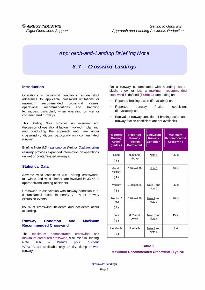
AIRBUS INDUSTRIE Getting to Grips with Flight Operations Support Approach-and-Landing Accidents Reduction
Crosswind Landings
Page 1
Approach-and-Landing Briefing Note
8.7 – Crosswind Landings
Introduction Operations in crosswind conditions require strict adherence to applicable crosswind limitations or maximum recommended crosswind values, operational recommendations and handling techniques, particularly when operating on wet or contaminated runways. This Briefing Note provides an overview and discussion of operational factors involved in planning and conducting the approach and flare under crosswind conditions, particularly on a contaminated runway. Briefing Note 8.5 – Landing on Wet or Contaminated Runway provides expanded information on operations on wet or contaminated runways.
Statistical Data Adverse wind conditions (i.e., strong crosswinds, tail winds and wind shear) are involved in 33 % of approach-and-landing accidents. Crosswind in association with runway condition is a circumstantial factor in nearly 70 % of runway excursion events. 85 % of crosswind incidents and accidents occur at landing.
Runway Condition and Maximum Recommended Crosswind The maximum demonstrated crosswind and maximum computed crosswind, discussed in Briefing Note 8.6 – What’s your Current Wind ?, are applicable only on dry, damp or wet runway.
On a runway contaminated with standing water, slush, snow or ice, a maximum recommended crosswind is defined (Table 1), depending on:
• Reported braking action (if available); or,
• Reported runway friction coefficient (if available); or,
• Equivalent runway condition (if braking action and runway friction coefficient are not available).
Reported Braking Action
( Index )
Reported Runway Friction
Coefficient
Equivalent Runway
Condition
Maximum Recommended
Crosswind
Good
( 5 )
0.40 and above
Note 1 35 kt
Good / Medium
( 4 )
0.36 to 0.39 Note 1 30 kt
Medium
( 3 )
0.30 to 0.35 Note 2 and Note 3
25 kt
Medium / Poor
( 2 )
0.26 to 0.29 Note 2 and Note 3
20 kt
Poor
( 1 )
0.25 and below
Note 3 and Note 4
15 kt
Unreliable
( 9 )
Unreliable Note 4 and Note 5
5 kt
Table 1
Maximum Recommended Crosswind - Typical

AIRBUS INDUSTRIE Getting to Grips with Flight Operations Support Approach-and-Landing Accidents Reduction
Crosswind Landings
Page 2
The Equivalent Runway Condition, defined by Note 1 through Note 5, can be used only for the determination of the maximum recommended crosswind. This Equivalent Runway Condition cannot be used for the computation of takeoff and landing performance, because it does not account for the effects of the displacement drag and impingement drag ( as defined in Briefing Note 8.5 – Landing on Wet or Contaminated Runway ).
Note 1 :
Dry, damp or wet runway (i.e., less than 3mm water depth) without risk of hydroplaning.
Note 2 :
Runway covered with slush.
Note 3 :
Runway covered with dry snow.
Note 4 :
Runway covered with standing water, with risk of hydroplaning, or with wet snow.
Note 5 :
Runway with high risk of hydroplaning.
The maximum recommended crosswind on a contaminated runway is based on computation rather than flight tests, but the calculated values are adjusted in a conservative manner based on operational experience. Some operators consider reduced maximum crosswind values when the first officer is PF, during line training and initial line operation. The maximum crosswind for performing an autoland is a certified limitation. Assignment by ATC of a given landing runway should be questioned by the PF if prevailing runway conditions and crosswind component are considered inadequate for a safe landing.
Final Approach Technique Figure 1 shows that depending on the recommendations published in the aircraft-operating manual, the final approach under crosswind conditions may be conducted :
• With wings-level (i.e., applying a drift correction in order to track the runway centerline, this type of approach is called a crabbed approach); or,
• With a steady sideslip (i.e., with the aircraft fuselage aligned with the runway centerline, using a combination of into-wind aileron and opposite rudder to correct the drift).
Figure 1
Crabbed Approach versus Sideslip Approach This Briefing Note focus on the wings-level / crabbed approach technique, recommended by Airbus Industrie, to discuss the associated flare and decrab techniques depending on the crosswind component.
Crabbed Approach Sideslip Approach

AIRBUS INDUSTRIE Getting to Grips with Flight Operations Support Approach-and-Landing Accidents Reduction
Crosswind Landings
Page 3
Airframe manufacturers consider the following factors when recommending a wings-level or a steady-side-slip approach :
• Aircraft geometry (i.e., pitch attitude and bank angle limits for preventing tail strike, engine nacelle contact or wingtip contact);
• Ailerons (roll) and rudder (yaw) authority; and,
• Crosswind component. Flare Technique Approaching the flare point with wings-level and with a crab angle, as required for drift correction, three flare techniques are possible (depending on runway condition, crosswind component and company SOPs):
• Align the aircraft with the runway centerline, while preventing drifting sideways, by applying into-wind aileron and opposite rudder (cross-controls);
• Perform a partial decrab, using the cross-controls technique to continue tracking the runway centerline; or,
• Maintain the crab angle, for drift correction, until main-landing-gear touchdown.
Understanding Crosswind Landing Limitations The following discussion of flight dynamics can provide an increased understanding of the various crosswind landing techniques (i.e., final approach, flare and align phases):
Crosswind landing capability – Design factors Figures 2 and Figure 3 illustrate the limitations involved in crosswind landing (for a given steady crosswind component).
• Bank angle at a given crab angle or crab angle at a given bank angle:
− The graph provides the bank angle / crab angle relationship required to correct the drift and track the runway centerline at the final approach speed ( V APP ) in a steady -side-slip condition.
Positive crab angles reflect normal drift corrections and sideslip conditions (i.e., with the aircraft pointing into wind).
Negative crab angles result from an excessive rudder correction (i.e., aircraft pointing away from wind direction) and require a more-than-desired bank angle to maintain a steady-sideslip.
• Aircraft geometry limitation :
− This limitation reflects the maximum pitch attitude and/or bank angle that can be achieved without incurring a tail strike or scrapping the engine nacelle, the flaps or the wingtip (as applicable).
• Ailerons / rudder authority :
− This limitation reflects the aircraft maximum capability to maintain a steady -sideslip under crosswind conditions.
Figure 2 and Figure 3 assume that the approach is stabilized and that the flare is performed at a normal height and with a normal pitch rate. These figures may not be available and published for all aircraft types and models, but all aircraft are subject to the same basic laws of flight dynamics that these figures reflect. Geometry limits usually are not a concern in high crosswinds as the roll and rudder authority is reached before any aircraft-to-ground contact occurs. This assumes achieving a steady sideslip without overcontrol (i.e., without excessive rudder and roll inputs) during the decrab / align phase.

AIRBUS INDUSTRIE Getting to Grips with Flight Operations Support Approach-and-Landing Accidents Reduction
Crosswind Landings
Page 4
Crab Angle versus Bank AngleTypical - Maximum Landing Weight - Landing Configuration - 10 kt Crosswind
-14
-12
-10
-8
-6
-4
-2
0
2
4
6
8
10
12
14
16
115 120 130 140 150 160
Indicated Airspeed (kt)
Cra
b A
ngle
(Deg
ree)
Pitch Attitude Limit
Roll / Rudder Limit
0 Degree Bank-Angle
2 Degree
4 Degree
6 Degree
8 Degree
10 Degree
12 Degree
V APP
B X
A X
Figure 2
Crab Angle versus Bank AngleTypical - Maximum Landing Weight - Landing Configuration - 30 kt Crosswind
-14
-12
-10
-8
-6
-4
-2
0
2
4
6
8
10
12
14
16
115 120 130 140 150 160
Indicated Airspeed (kt)
Cra
b A
ng
le (D
egre
e)
Pitch Attitude Limit
Roll / Rudder Limit
0 Degree Bank-Angle
2 Degree
4 Degree
6 Degree
8 Degree
10 Degree
12 Degree
V APP
A X
C X
B X
X D
Figure 3

AIRBUS INDUSTRIE Getting to Grips with Flight Operations Support Approach-and-Landing Accidents Reduction
Crosswind Landings
Page 5
Figure 2 shows that with a 10 kt steady crosswind component:
• Achieving a steady sideslip landing (i.e., with zero crab angle) requires only a 3-degree into-wing bank angle ( point A plotted on the graph ); or,
• Achieving a wings level touchdown (i.e., with no decrab) only requires a 4-degree to 5-degree crab angle at touchdown ( point B ).
A steady-sideslip landing can be performed safely (i.e., while retaining significant margins relative to geometry or roll / rudder limits). Figure 3 shows that with a 30 kt steady crosswind component:
• Achieving a steady-sideslip landing (i.e., with zero crab angle) requires nearly a 9-degree into-wind bank angle, placing the aircraft closer to its geometry and roll /r udder limits ( point A on the graph ); or,
• Achieving a wings-level touchdown (i.e., with no decrab) would result in a 13-degree crab angle at touchdown, potentially resulting in landing gear damage ( point B ).
With 30 kt crosswind, adopting a combination of sideslip and crab-angle (i.e., moving from point A to point C ) restores significant margins relative to geometry and roll / rudder limits while eliminating the risk of landing gear damage). This requires, typically:
• 5 degrees of crab angle; and,
• 5 degrees of bank angle,
On aircraft models limited by their geometry characteristics, increasing the final approach speed (i.e., by applying a wind correction on the final approach speed, even under full crosswind, thus moving from point A to point D ) increases the margin with respect to the geometry limitation.
Operational recommendations and handling techniques
Figure 2 and Figure 3 shows that:
• With low crosswind ( typically up to 15 kt to 20 kt crosswind component ), a safe crosswind landing (i.e., flare and touchdown) can be performed with either:
− A steady-sideslip (i.e., no crab angle); or,
− Wings-level, with no decrab prior to touchdown.
• With higher crosswind ( typically above 15 kt to 20 kt crosswind component ), a safe crosswind landing requires:
− a crabbed-approach; and,
− a partial decrab prior to touchdown, using a combination of bank angle and crab angle (achieved by applying cross-controls).
On most Airbus models, this requires touching down with:
− 5 degrees of crab angle; and,
− 5 degrees of bank angle.
The decision to perform the flare with no decrab, with partial decrab or with complete decrab should depend upon the prevailing crosswind component but also on the following factors (or as specified by company’ SOPs):
• Wind gustiness;
• Runway length;
• Runway surface condition;
• Type of aircraft; and,
• Pilot experience on type.
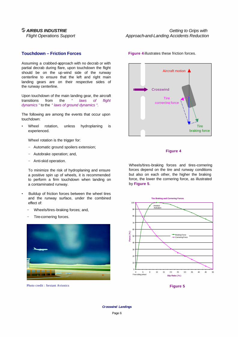
AIRBUS INDUSTRIE Getting to Grips with Flight Operations Support Approach-and-Landing Accidents Reduction
Crosswind Landings
Page 6
Touchdown – Friction Forces Assuming a crabbed-approach with no decrab or with partial decrab during flare, upon touchdown the flight should be on the up-wind side of the runway centerline to ensure that the left and right main landing gears are on their respective sides of the runway centerline. Upon touchdown of the main landing gear, the aircraft transitions from the “ laws of flight dynamics “ to the “ laws of ground dynamics “. The following are among the events that occur upon touchdown:
• Wheel rotation, unless hydroplaning is experienced. Wheel rotation is the trigger for:
− Automatic ground spoilers extension;
− Autobrake operation; and,
− Anti-skid operation.
To minimize the risk of hydroplaning and ensure a positive spin up of wheels, it is recommended to perform a firm touchdown when landing on a contaminated runway.
• Buildup of friction forces between the wheel tires and the runway surface, under the combined effect of:
− Wheels/tires-braking forces; and,
− Tire-cornering forces.
Figure 4 illustrates these friction forces.
Figure 4
Wheels/tires-braking forces and tires-cornering forces depend on the tire and runway conditions but also on each other, the higher the braking force, the lower the cornering force, as illustrated by Figure 5. Figure 5
Tire Braking and Cornering Forces
0
10
20
30
40
50
60
70
80
90
100
0 5 8 10 15 20 25 30 35 40 45 50
Slip Ratio ( % )
Forc
e ( %
)
Braking ForceCornering Force
Free rolling wheel
Antiskid Activation
Photo credit : Sextant Avionics
Aircraft motion
Tire cornering force
Tire braking force
Crosswind

AIRBUS INDUSTRIE Getting to Grips with Flight Operations Support Approach-and-Landing Accidents Reduction
Crosswind Landings
Page 7
Transient effects such as the distortion of the tire thread ( caused by any yawing movement of the wheel ) or the activation of the anti-skid system affect the tire-cornering and wheel-braking forces ( in both magnitude and direction ) and, thus, affect the overall balance of friction forces. As a consequence, the ideal balance of forces illustrated by Figure 3 rarely is steadily maintained during the initial landing roll.
Effect of Touchdown on Alignment When touching down with some crab angle on a dry runway, the aircraft automatically realigns with the direction of travel down the runway. On a contaminated runway, the aircraft tends to travel along the runway centerline with the existing crab angle.
Effect of Fuselage and Fin Side Force As the aircraft touches down, the side force created by the crosswind component on the fuselage and fin tends to make the aircraft skid sideways (downwind) off the centerline, as illustrated by Figure 6. Effect of Thrust Reversers When selecting reverse thrust with some crab angle, the reverse thrust results into two force components, as illustrated by Figure 6:
• A stopping force aligned along the aircraft direction of travel (runway centerline); and,
• A side force, perpendicular to the runway centerline, which further increases the tendency to skid sideways.
Figure 6
Directional Control during Crosswind Landing
Touchdown with partial
decrab
Aircraft skidding sideways
due to fuselage/fin side force
and reverse thrust side
force
Reverse cancelled
and brakes released
Directional control and centerline regained
Reverse thrust and
pedal braking
reapplied
Crosswind component

AIRBUS INDUSTRIE Getting to Grips with Flight Operations Support Approach-and-Landing Accidents Reduction
Crosswind Landings
Page 8
The thrust reverser effect decreases with decreasing airspeed. As airspeed decreases, the rudder efficiency decreases and is further affected by the airflow disruption created in the wake of the engine reverse flow, possibly resulting in difficulties to maintain directional control. Effect of Braking In a high crosswind, cross-controls may have to be maintained after touchdown to prevent the into-wind wing from lifting and to counteract the weather-vane effect (some flight crew training manuals adequately state that the pilot should continue to fly the aircraft during the landing roll ). However, into-wind aileron decreases the lift on the into-wind wing, thus resulting in an increased load on the into-wind landing gear. Because the friction force increases as higher loads are applied on the wheels and tires, the braking force increases on the into-wind landing gear, creating an additional tendency to turn into-wind, as illustrated by Figure 7. When the runway contaminant is not evenly distributed, the antiskid system may release the brakes on one side only.
Figure 7
Effect of Uneven MLG Loads on Braking
Maintaining / Regaining Directional Control The higher the wheel/tire braking force, the lower the tire-cornering force; therefore, if the aircraft tends to skid sideways, releasing the brakes (i.e., by taking over from the autobrake) increases the tire-cornering and contributes to maintaining or regaining directional control. Selecting reverse idle cancels the effects of reverse thrust (i.e., the side force and rudder airflow disruption) and, thus, further assists in regaining directional control. After directional control has been recovered and the runway centerline has been regained:
• Pedal braking can be applied (autobrake was previously disarmed when taking over) in a symmetrical or differential manner, as required; and,
• Reverse thrust can be reselected. Optimum Braking Refer to Briefing Note 8.4 – Optimum Use of Braking Devices. Factors Involved in Crosswind-Landing Incidents and Accidents The following factors often are involved in crosswind-landing incidents and accidents:
• Reluctance to recognize changes in landing data over time (i.e., wind direction shift, wind velocity or gust increase);
• Failure to seek additional evidence to confirm the initial information and initial options (i.e., reluctance to change pre-established plans);
• Reluctance to divert to an airport with less crosswind conditions;
• Lack of time to observe, evaluate and control the aircraft attitude and flight path in a highly dynamic situation;

AIRBUS INDUSTRIE Getting to Grips with Flight Operations Support Approach-and-Landing Accidents Reduction
Crosswind Landings
Page 9
• Difficulties with pitching effect of under-wing-mounted engines in gusty conditions (i.e., head-on gust effect on indicated airspeed and pitch attitude); and,
• Ineffective differential braking due to the partial release of the brake pedal (i.e., if the brake pedal is only partially released, the braking demand may still exceed the anti-skid regulated pressure and, thus, still produce a symmetrical braking action).
Summary of Key Points Adherence to the following key points increases safety during crosswind-landing operations:
• Understand all applicable operating factors, maximum recommended values and limitations;
• Use recommended and published flying techniques associated with crosswind landing;
Note :
A wings-level touchdown (i.e., without any decrab) may be safer than a steady-sideslip touchdown with an excessive bank angle;
• Request the assignment of a more favorable runway, if prevailing runway conditions and crosswind component are considered inadequate for a safe landing;
• Adapt the autopilot disconnect altitude to prevailing conditions in order to have time to establish manual control and trim the aircraft (conventional aircraft models) before the align / decrab phase and flare;
• Be alert to detect changes in ATIS and tower messages (i.e., wind direction shift, velocity and/or gust increase); and,
• Beware of small-scale local effects associated with strong winds:
− Updrafts and downdrafts;
− Vortices created by buildings, forests or terrain.
Associated Briefing Notes The following Briefing Notes complement the above information and provide a comprehensive overview of landing techniques:
8.1 – Preventing Runway Excursions and Overruns,
8.2 – The Final Approach Speed,
8.3 – Factors Affecting Landing Distances,
8.4 – Optimum Use of Braking Devices,
8.5 – Landing on Wet and Contaminated Runway,
8.6 – What’s Your Current Wind ? Regulatory References
• ICAO – Preparation of an Operations Manual (Doc 9376).
• JAR-OPS 1.1045 and associated Appendix 1, 2.1.(n) – Operations manual – structure and contents.