archtecture overview gigamon resilient inline protection · gigamon resilient inline protection...
TRANSCRIPT
© 2018 Gigamon. All rights reserved. 1
The Challenges of Deploying Inline Security ToolsMaximizing both network uptime and network security is a challenge for any organization. As more tools move from an out-of-band detection mode to an inline active protection mode, network resiliency becomes a particular concern. Inline security appliances represent potential points of failure in the network. Whether due to a power outage, software malfunction, or processing bottleneck, failing inline tools can disrupt the very applications and services they are meant to protect. Moreover, redundant network architectures are designed to be fault-resilient, but they present their own challenges when it comes to inline inspection of traffic.
Gigamon Resilient Inline Protection (GRIP™) is a resilient inline architecture that utilizes the HC Series nodes to address these concerns as part of the Gigamon Security Delivery Platform. GRIP leverages both inline tool redundancy and bypass protection to optimize network uptime without sacrificing security.
Redundant Inline ToolsRedundant inline tools address resiliency with the simple principle that if one tool fails, the redundant tool takes over. This is also known as 1+1 protection. An inline HC Series node is required to detect the failure of the active tool and redirect traffic to the standby tool. The health of an inline tools is determined by monitoring the state of the link and optionally sending bidirectional heartbeat packets that verify the tool is passing traffic. The parameters of the heartbeat packets can also be finetuned to trigger a failover to the standby tool when the latency of the active tool becomes too great.
Rather than have an active/standby arrangement, the HC Series node can distribute traffic across multiple inline tools. Should one tool fail, the visibility node redistributes the traffic to the remaining, healthy tools. These inline tool groups also allow security monitoring to scale up to network speeds.
Bypass ProtectionBypass protection comes in two varieties: logical and physical. Both operate on the principle that traffic continuity must be maintained even if the traffic cannot be inspected. This is also known as fail to wire. Many organizations deploy a security policy that forbids fail to wire. In highly sensitive environments, it may be preferable to have a disruption in network traffic than allow uninspected traffic into the network. These cases can still benefit from deploying redundant tools, but would not benefit from bypass protection or GRIP™.
A R C H T E C T U R E O V E R V I E W
Gigamon Resilient Inline ProtectionWith logical bypass, the traffic is forwarded to the network should the inline tool fail. When deploying redundant inline tools, bypass protection is applied if/when both the active and standby tool is down. Or if multiple tools are present, traffic is bypassed when a certain number of the tools have failed.
In order to optimize inline tool performance, the HC Series node can be configured to only send a portion of the network traffic to the tool and bypass the rest. For example, a tool that is designed to inspect a particular type of application, such as database or email traffic, will benefit if only that type of traffic is sent to the tool. The processing load on the tool can be reduced and the performance enhanced by only sending it traffic on specific subnets, VLANs, or TCP/UDP ports, and bypassing the rest. The power of inline Flow Mapping® technology allows the HC Series node to send different traffic to separate tools for inspection.
Physical bypass protection avoids any problem with power failure of the visibility node itself. In the event of a power failure, relays complete the network circuit and keep traffic flowing. The relays are designed such that they require power to access the network traffic (so that it can be forwarded to the inline tools) and switching to protected mode occurs automatically and without software intervention upon the loss of power.
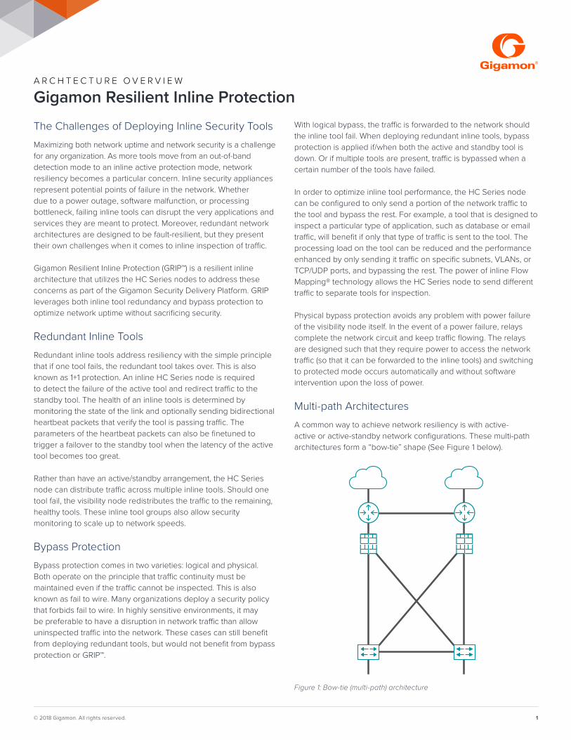
Multi-path ArchitecturesA common way to achieve network resiliency is with active-active or active-standby network configurations. These multi-path architectures form a “bow-tie” shape (See Figure 1 below).
Figure 1: Bow-tie (multi-path) architecture
ARCHITECTURE OVERVIEW | GIGAMON RESILIENT INLINE PROTECTION
© 2018 Gigamon. All rights reserved. 2
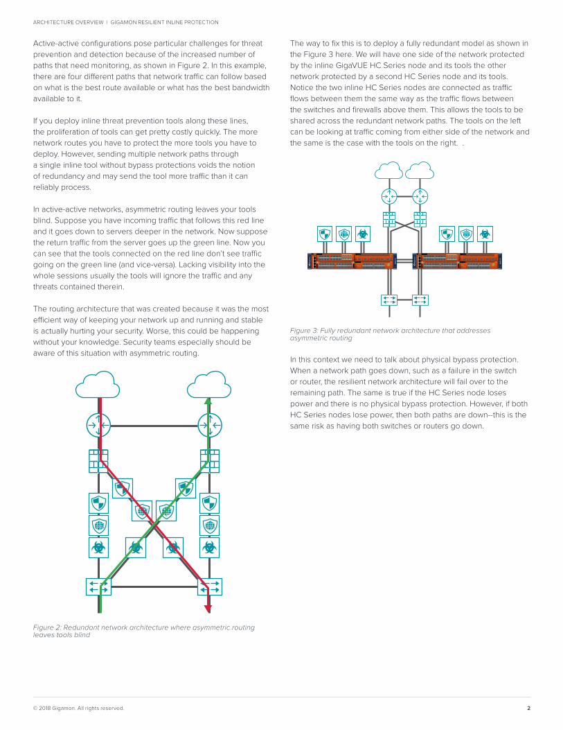
Active-active configurations pose particular challenges for threat prevention and detection because of the increased number of paths that need monitoring, as shown in Figure 2. In this example, there are four different paths that network traffic can follow based on what is the best route available or what has the best bandwidth available to it.
If you deploy inline threat prevention tools along these lines, the proliferation of tools can get pretty costly quickly. The more network routes you have to protect the more tools you have to deploy. However, sending multiple network paths through a single inline tool without bypass protections voids the notion of redundancy and may send the tool more traffic than it can reliably process.
In active-active networks, asymmetric routing leaves your tools blind. Suppose you have incoming traffic that follows this red line and it goes down to servers deeper in the network. Now suppose the return traffic from the server goes up the green line. Now you can see that the tools connected on the red line don’t see traffic going on the green line (and vice-versa). Lacking visibility into the whole sessions usually the tools will ignore the traffic and any threats contained therein.
The routing architecture that was created because it was the most efficient way of keeping your network up and running and stable is actually hurting your security. Worse, this could be happening without your knowledge. Security teams especially should be aware of this situation with asymmetric routing.
The way to fix this is to deploy a fully redundant model as shown in the Figure 3 here. We will have one side of the network protected by the inline GigaVUE HC Series node and its tools the other network protected by a second HC Series node and its tools. Notice the two inline HC Series nodes are connected as traffic flows between them the same way as the traffic flows between the switches and firewalls above them. This allows the tools to be shared across the redundant network paths. The tools on the left can be looking at traffic coming from either side of the network and the same is the case with the tools on the right. .
In this context we need to talk about physical bypass protection. When a network path goes down, such as a failure in the switch or router, the resilient network architecture will fail over to the remaining path. The same is true if the HC Series node loses power and there is no physical bypass protection. However, if both HC Series nodes lose power, then both paths are down--this is the same risk as having both switches or routers go down.
Figure 2: Redundant network architecture where asymmetric routing leaves tools blind
Figure 3: Fully redundant network architecture that addresses asymmetric routing
FanPPS Rear
RdyPwr
M/S
Lock
PTPIEEE1588
StackMgmtPort
Mgmt
Con-sole
GigaVUE-HC2
1
1
2
3
4
X1 X3 X5 X7 X9 X11
X2 X4 X6 X8 X10 X12
X13 X15 X17 X19 X21 X23
X14 X16 X18 X20 X24GigaPORT-X24
X22
PR
T-H
C0-
Q06
Rdy
Pwr
Q1 LNK
ENA
Q1 LNK
ENA
Q1 LNK
ENA
Q1 LNK
ENA
Q1 LNK
ENA
Q1 LNK
ENA
X1X2
Rdy
Pwr
SMT-HC0
-X16
X3X4
X5X6
X7X8
X9X10
X11X12
X13X14
X15X16
H/S
X1X2
Rdy
Pwr BPS -HC 0
-D2 5A 4
G
X3X4
X5X6
X7X8
X9X10
X11X12
X13X14
X15X16
B MANET WORK 1
B MANET WORK 2
B MANET WORK 3
B MANET WORK 4
MOD
E (M
)Off
= B
y pas
sOn
= In
line
SX / SR 50 um

ARCHITECTURE OVERVIEW | GIGAMON RESILIENT INLINE PROTECTION
© 2018 Gigamon. All rights reserved. 3
However, when you use physical bypass, if one path goes down as shown in this diagram where one HC Series node is down, and you are using physical bypass that leaves the path up (Figure 4) but vulnerable since you are not inspecting that traffic. In this case, the tools on the right side are working fine but you have lost your symmetry and you will have the asymmetric routing problem all over again.
Due to this reason, it is recommended not to use bypass protection if one of the HC Series nodes goes down. This enables the network to do its job and failover all the network traffic to the other path (Figure 5). This way you know the other path is going to be protected and the network is doing what it was designed to do.
Single Path ArchitecturesGRIP supports a variety of different deployment options, including single or multiple network links protected by one or more inline tools. Figure 6 below is an example of a serial GRIP with single network link. The two HC Series nodes are also connected via a 10G status link that the secondary HC Series node uses to monitor the state of the primary node. Figure 7 is a description of one common arrangement in which two redundant network links are protected by two Intrusion Protection Systems (IPSes) deployed inline. Two HC Series nodes provide additional resiliency; one is designated as primary and one is secondary. Both are connected to both inline IPSes.
Figure 7: Traffic path while the primary HC Series node is up
FanPPS Rear
RdyPwr
M/S
Lock
PTPIEEE1588
StackMgmtPort
Mgmt
Con-sole
GigaVUE-HC2
1
1
2
3
4
X1 X3 X5 X7 X9 X11
X2 X4 X6 X8 X10 X12
X13 X15 X17 X19 X21 X23
X14 X16 X18 X20 X24GigaPORT-X24
X22
PR
T-H
C0-
Q06
Rdy
Pwr
Q1 LNK
ENA
Q1 LNK
ENA
Q1 LNK
ENA
Q1 LNK
ENA
Q1 LNK
ENA
Q1 LNK
ENA
X1X2
Rdy
Pwr
SMT-HC0
-X16
X3X4
X5X6
X7X8
X9X10
X11X12
X13X14
X15X16
H/S
X1X2
Rdy
Pwr BPS-HC0
-D25A4
G
X3X4
X5X6
X7X8
X9X10
X11X12
X13X14
X15X16
B MANET WORK 1
B MANET WORK 2
B MANET WORK 3
B MANET WORK 4
MOD
E (M
)Off
= B
ypas
sOn
= In
line
SX / SR 50 um
Stack linkactive
Figure 5: Not using physical bypass allows network failover to do its job
FanPPS Rear
RdyPwr
M/S
Lock
PTPIEEE1588
StackMgmtPort
Mgmt
Con-sole
GigaVUE-HC2
1
1
2
3
4
X1 X3 X5 X7 X9 X11
X2 X4 X6 X8 X10 X12
X13 X15 X17 X19 X21 X23
X14 X16 X18 X20 X24GigaPORT-X24
X22
PR
T-H
C0-
Q06
Rdy
Pwr
Q1 LNK
ENA
Q1 LNK
ENA
Q1 LNK
ENA
Q1 LNK
ENA
Q1 LNK
ENA
Q1 LNK
ENA
X1X2
Rdy
Pwr
SMT-HC0
-X16
X3X4
X5X6
X7X8
X9X10
X11X12
X13X14
X15X16
H/S
X1X2
Rdy
Pwr BPS -HC 0
-D2 5A 4
G
X3X4
X5X6
X7X8
X9X10
X11X12
X13X14
X15X16
B MANET WORK 1
B MANET WORK 2
B MANET WORK 3
B MANET WORK 4
MOD
E (M
)Off
= B
y pas
sOn
= In
line
SX / SR 50 um
FanPPS Rear
RdyPwr
M/S
Lock
PTPIEEE1588
StackMgmtPort
Mgmt
Con-sole
GigaVUE-HC2
1
1
2
3
4
X1 X3 X5 X7 X9 X11
X2 X4 X6 X8 X10 X12
X13 X15 X17 X19 X21 X23
X14 X16 X18 X20 X24GigaPORT-X24
X22
PR
T-H
C0-
Q06
Rdy
Pwr
Q1 LNK
ENA
Q1 LNK
ENA
Q1 LNK
ENA
Q1 LNK
ENA
Q1 LNK
ENA
Q1 LNK
ENA
X1X2
Rdy
Pwr
SMT-HC0
-X16
X3X4
X5X6
X7X8
X9X10
X11X12
X13X14
X15X16
H/S
X1X2
Rdy
Pwr BPS -HC 0
-D2 5A 4
G
X3X4
X5X6
X7X8
X9X10
X11X12
X13X14
X15X16
B MANET WORK 1
B MANET WORK 2
B MANET WORK 3
B MANET WORK 4
MOD
E (M
)Off
= B
y pas
sOn
= In
line
SX / SR 50 umX
Figure 6: Serial GRIP. The HC Series node can distribute traffic across multiple inline tools; in the event of a tool failure, the traffic can be redistributed to the remaining healthy tools or to a dedicated standby tool
FanPPS Rear
RdyPwr
M/S
Lock
PTPIEEE1588
StackMgmtPort
Mgmt
Con-sole
GigaVUE-HC2
1
1
2
3
4
X1 X3 X5 X7 X9 X11
X2 X4 X6 X8 X10 X12
X13 X15 X17 X19 X21 X23
X14 X16 X18 X20 X24GigaPORT-X24
X22
PR
T-H
C0-
Q06
Rdy
Pwr
Q1 LNK
ENA
Q1 LNK
ENA
Q1 LNK
ENA
Q1 LNK
ENA
Q1 LNK
ENA
Q1 LNK
ENA
X1X2
Rdy
Pwr
SMT-HC0
-X16
X3X4
X5X6
X7X8
X9X10
X11X12
X13X14
X15X16
H/S
X1X2
Rdy
Pwr BPS-HC0
-D25A4
G
X3X4
X5X6
X7X8
X9X10
X11X12
X13X14
X15X16
B MANET WORK 1
B MANET WORK 2
B MANET WORK 3
B MANET WORK 4
MOD
E (M
)Off
= B
ypas
sOn
= In
line
SX / SR 50 um
Stack linkconnected
Figure 4: Using physical bypass leaves one side up, but vulnerable
FanPPS Rear
RdyPwr
M/S
Lock
PTPIEEE1588
StackMgmtPort
Mgmt
Con-sole
GigaVUE-HC2
1
1
2
3
4
X1 X3 X5 X7 X9 X11
X2 X4 X6 X8 X10 X12
X13 X15 X17 X19 X21 X23
X14 X16 X18 X20 X24GigaPORT-X24
X22
PR
T-H
C0-
Q06
Rdy
Pwr
Q1 LNK
ENA
Q1 LNK
ENA
Q1 LNK
ENA
Q1 LNK
ENA
Q1 LNK
ENA
Q1 LNK
ENA
X1X2
Rdy
Pwr
SMT-HC0
-X16
X3X4
X5X6
X7X8
X9X10
X11X12
X13X14
X15X16
H/S
X1X2
Rdy
Pwr BPS -HC 0
-D2 5A 4
G
X3X4
X5X6
X7X8
X9X10
X11X12
X13X14
X15X16
B MANET WORK 1
B MANET WORK 2
B MANET WORK 3
B MANET WORK 4
MOD
E (M
)Off
= B
y pas
sOn
= In
line
SX / SR 50 um
FanPPS Rear
RdyPwr
M/S
Lock
PTPIEEE1588
StackMgmtPort
Mgmt
Con-sole
GigaVUE-HC2
1
1
2
3
4
X1 X3 X5 X7 X9 X11
X2 X4 X6 X8 X10 X12
X13 X15 X17 X19 X21 X23
X14 X16 X18 X20 X24GigaPORT-X24
X22
PR
T-H
C0-
Q06
Rdy
Pwr
Q1 LNK
ENA
Q1 LNK
ENA
Q1 LNK
ENA
Q1 LNK
ENA
Q1 LNK
ENA
Q1 LNK
ENA
X1X2
Rdy
Pwr
SMT-HC0
-X16
X3X4
X5X6
X7X8
X9X10
X11X12
X13X14
X15X16
H/S
X1X2
Rdy
Pwr BPS -HC 0
-D2 5A 4
G
X3X4
X5X6
X7X8
X9X10
X11X12
X13X14
X15X16
B MANET WORK 1
B MANET WORK 2
B MANET WORK 3
B MANET WORK 4
MOD
E (M
)Off
= B
y pas
sOn
= In
line
SX / SR 50 umX

ARCHITECTURE OVERVIEW | GIGAMON RESILIENT INLINE PROTECTION
Worldwide Headquarters 3300 Olcott Street, Santa Clara, CA 95054 USA+1 (408) 831-4000 | www.gigamon.com
© 2018 Gigamon. All rights reserved. Gigamon and the Gigamon logo are trademarks of Gigamon in the United States and/or other countries. Gigamon trademarks can be found at www.gigamon.com/legal-trademarks. All other trademarks are the trademarks of their respective owners. Gigamon reserves the right to change, modify, transfer, or otherwise revise this publication without notice.
3183-03 11/18
In standard operation, the primary HC Series node forwards network traffic to the IPSes. The secondary HC Series node is in a standby mode with its inline network ports physically bypassing the traffic. Thus, only a single copy of the traffic is sent to the IPSes.
If the primary HC Series node loses power, the status link will turn off and the secondary node is triggered to disengage its physical bypass relay and begin sending traffic to the inline tools. When the primary HC Series node recovers and the signaling link returns, the secondary node again engages its physical bypass.
VariationsGRIP also works with out-of-band security tools, either instead of or in concert with inline tools. In addition, more complex and sophisticated arrangements of inline tools is also supported. For example, GRIP can be configured with multiple inline tools arranged serially, each inspecting network traffic, such as IPS, web application firewalls (WAF), and anti-malware appliances.
Gigamon is enabling the collaboration between network and security operations to reduce complexity and increase efficiency of the security stack. The Gigamon Security Delivery Platform is a next generation network packet broker purpose-built for security that helps organizations make threats more visible – across cloud, hybrid and on-premises environments, deploy resources faster and maximize the performance of security tools. Global 2000 companies and government agencies rely on Gigamon solutions to stop tool sprawl and save costs.
For more information about the Gigamon Security Delivery Platform visit: www.gigamon.com.
Figure 9: If both the primary and secondary HC Series nodes go down, network traffic integrity is maintained
FanPPS Rear
RdyPwr
M/S
Lock
PTPIEEE1588
StackMgmtPort
Mgmt
Con-sole
GigaVUE-HC2
1
1
2
3
4
X1 X3 X5 X7 X9 X11
X2 X4 X6 X8 X10 X12
X13 X15 X17 X19 X21 X23
X14 X16 X18 X20 X24GigaPORT-X24
X22
PR
T-H
C0-
Q06
Rdy
Pwr
Q1 LNK
ENA
Q1 LNK
ENA
Q1 LNK
ENA
Q1 LNK
ENA
Q1 LNK
ENA
Q1 LNK
ENA
X1X2
Rdy
Pwr
SMT-HC0
-X16
X3X4
X5X6
X7X8
X9X10
X11X12
X13X14
X15X16
H/S
X1X2
Rdy
Pwr BPS-HC0
-D25A4
G
X3X4
X5X6
X7X8
X9X10
X11X12
X13X14
X15X16
B MANET WORK 1
B MANET WORK 2
B MANET WORK 3
B MANET WORK 4
MOD
E (M
)Off
= B
ypas
sOn
= In
line
SX / SR 50 um
Power down
FanPPS Rear
RdyPwr
M/S
Lock
PTPIEEE1588
StackMgmtPort
Mgmt
Con-sole
GigaVUE-HC2
1
1
2
3
4
X1 X3 X5 X7 X9 X11
X2 X4 X6 X8 X10 X12
X13 X15 X17 X19 X21 X23
X14 X16 X18 X20 X24GigaPORT-X24
X22
PR
T-H
C0-
Q06
Rdy
Pwr
Q1 LNK
ENA
Q1 LNK
ENA
Q1 LNK
ENA
Q1 LNK
ENA
Q1 LNK
ENA
Q1 LNK
ENA
X1X2
Rdy
Pwr
SMT-HC0
-X16
X3X4
X5X6
X7X8
X9X10
X11X12
X13X14
X15X16
H/S
X1X2
Rdy
Pwr BPS-HC0
-D25A4
G
X3X4
X5X6
X7X8
X9X10
X11X12
X13X14
X15X16
B MANET WORK 1
B MANET WORK 2
B MANET WORK 3
B MANET WORK 4
MOD
E (M
)Off
= B
ypas
sOn
= In
line
SX / SR 50 um
Stack linkinactive
Power down
Figure 8: Traffic path should the primary HC Series node lose power; the secondary node forwards the traffic to the security tools
FanPPS Rear
RdyPwr
M/S
Lock
PTPIEEE1588
StackMgmtPort
Mgmt
Con-sole
GigaVUE-HC2
1
1
2
3
4
X1 X3 X5 X7 X9 X11
X2 X4 X6 X8 X10 X12
X13 X15 X17 X19 X21 X23
X14 X16 X18 X20 X24GigaPORT-X24
X22
PR
T-H
C0-
Q06
Rdy
Pwr
Q1 LNK
ENA
Q1 LNK
ENA
Q1 LNK
ENA
Q1 LNK
ENA
Q1 LNK
ENA
Q1 LNK
ENA
X1X2
Rdy
Pwr
SMT-HC0
-X16
X3X4
X5X6
X7X8
X9X10
X11X12
X13X14
X15X16
H/S
X1X2
Rdy
Pwr BPS-HC0
-D25A4
G
X3X4
X5X6
X7X8
X9X10
X11X12
X13X14
X15X16
B MANET WORK 1
B MANET WORK 2
B MANET WORK 3
B MANET WORK 4
MOD
E (M
)Off
= B
ypas
sOn
= In
line
SX / SR 50 um
Stack linkinactive
Power down
Should both the primary and secondary HC Series nodeslose power, both sets of physical bypass relays will be engaged,preserving network continuity. Thus, GRIP provides three layersof resiliency: support for redundant network architectures,redundant inline tools, and redundant HC Series nodes.